WO2018092338A1 - 燃料供給装置、並びに、燃料供給装置の取り付け及び取り外し方法 - Google Patents
燃料供給装置、並びに、燃料供給装置の取り付け及び取り外し方法 Download PDFInfo
- Publication number
- WO2018092338A1 WO2018092338A1 PCT/JP2017/021418 JP2017021418W WO2018092338A1 WO 2018092338 A1 WO2018092338 A1 WO 2018092338A1 JP 2017021418 W JP2017021418 W JP 2017021418W WO 2018092338 A1 WO2018092338 A1 WO 2018092338A1
- Authority
- WO
- WIPO (PCT)
- Prior art keywords
- pump unit
- supply device
- fuel supply
- opening
- fuel tank
- Prior art date
- Legal status (The legal status is an assumption and is not a legal conclusion. Google has not performed a legal analysis and makes no representation as to the accuracy of the status listed.)
- Ceased
Links
Images




Classifications
-
- F—MECHANICAL ENGINEERING; LIGHTING; HEATING; WEAPONS; BLASTING
- F02—COMBUSTION ENGINES; HOT-GAS OR COMBUSTION-PRODUCT ENGINE PLANTS
- F02M—SUPPLYING COMBUSTION ENGINES IN GENERAL WITH COMBUSTIBLE MIXTURES OR CONSTITUENTS THEREOF
- F02M37/00—Apparatus or systems for feeding liquid fuel from storage containers to carburettors or fuel-injection apparatus; Arrangements for purifying liquid fuel specially adapted for, or arranged on, internal-combustion engines
- F02M37/04—Feeding by means of driven pumps
- F02M37/08—Feeding by means of driven pumps electrically driven
- F02M37/10—Feeding by means of driven pumps electrically driven submerged in fuel, e.g. in reservoir
- F02M37/103—Mounting pumps on fuel tanks
-
- B—PERFORMING OPERATIONS; TRANSPORTING
- B60—VEHICLES IN GENERAL
- B60K—ARRANGEMENT OR MOUNTING OF PROPULSION UNITS OR OF TRANSMISSIONS IN VEHICLES; ARRANGEMENT OR MOUNTING OF PLURAL DIVERSE PRIME-MOVERS IN VEHICLES; AUXILIARY DRIVES FOR VEHICLES; INSTRUMENTATION OR DASHBOARDS FOR VEHICLES; ARRANGEMENTS IN CONNECTION WITH COOLING, AIR INTAKE, GAS EXHAUST OR FUEL SUPPLY OF PROPULSION UNITS IN VEHICLES
- B60K15/00—Arrangement in connection with fuel supply of combustion engines or other fuel consuming energy converters, e.g. fuel cells; Mounting or construction of fuel tanks
- B60K15/03—Fuel tanks
-
- B—PERFORMING OPERATIONS; TRANSPORTING
- B60—VEHICLES IN GENERAL
- B60K—ARRANGEMENT OR MOUNTING OF PROPULSION UNITS OR OF TRANSMISSIONS IN VEHICLES; ARRANGEMENT OR MOUNTING OF PLURAL DIVERSE PRIME-MOVERS IN VEHICLES; AUXILIARY DRIVES FOR VEHICLES; INSTRUMENTATION OR DASHBOARDS FOR VEHICLES; ARRANGEMENTS IN CONNECTION WITH COOLING, AIR INTAKE, GAS EXHAUST OR FUEL SUPPLY OF PROPULSION UNITS IN VEHICLES
- B60K15/00—Arrangement in connection with fuel supply of combustion engines or other fuel consuming energy converters, e.g. fuel cells; Mounting or construction of fuel tanks
- B60K15/03—Fuel tanks
- B60K2015/0321—Fuel tanks characterised by special sensors, the mounting thereof
- B60K2015/03217—Fuel level sensors
-
- B—PERFORMING OPERATIONS; TRANSPORTING
- B60—VEHICLES IN GENERAL
- B60K—ARRANGEMENT OR MOUNTING OF PROPULSION UNITS OR OF TRANSMISSIONS IN VEHICLES; ARRANGEMENT OR MOUNTING OF PLURAL DIVERSE PRIME-MOVERS IN VEHICLES; AUXILIARY DRIVES FOR VEHICLES; INSTRUMENTATION OR DASHBOARDS FOR VEHICLES; ARRANGEMENTS IN CONNECTION WITH COOLING, AIR INTAKE, GAS EXHAUST OR FUEL SUPPLY OF PROPULSION UNITS IN VEHICLES
- B60K15/00—Arrangement in connection with fuel supply of combustion engines or other fuel consuming energy converters, e.g. fuel cells; Mounting or construction of fuel tanks
- B60K15/03—Fuel tanks
- B60K2015/03243—Fuel tanks characterised by special pumps, the mounting thereof
-
- B—PERFORMING OPERATIONS; TRANSPORTING
- B60—VEHICLES IN GENERAL
- B60K—ARRANGEMENT OR MOUNTING OF PROPULSION UNITS OR OF TRANSMISSIONS IN VEHICLES; ARRANGEMENT OR MOUNTING OF PLURAL DIVERSE PRIME-MOVERS IN VEHICLES; AUXILIARY DRIVES FOR VEHICLES; INSTRUMENTATION OR DASHBOARDS FOR VEHICLES; ARRANGEMENTS IN CONNECTION WITH COOLING, AIR INTAKE, GAS EXHAUST OR FUEL SUPPLY OF PROPULSION UNITS IN VEHICLES
- B60K15/00—Arrangement in connection with fuel supply of combustion engines or other fuel consuming energy converters, e.g. fuel cells; Mounting or construction of fuel tanks
- B60K15/03—Fuel tanks
- B60K2015/03328—Arrangements or special measures related to fuel tanks or fuel handling
- B60K2015/03453—Arrangements or special measures related to fuel tanks or fuel handling for fixing or mounting parts of the fuel tank together
-
- B—PERFORMING OPERATIONS; TRANSPORTING
- B60—VEHICLES IN GENERAL
- B60K—ARRANGEMENT OR MOUNTING OF PROPULSION UNITS OR OF TRANSMISSIONS IN VEHICLES; ARRANGEMENT OR MOUNTING OF PLURAL DIVERSE PRIME-MOVERS IN VEHICLES; AUXILIARY DRIVES FOR VEHICLES; INSTRUMENTATION OR DASHBOARDS FOR VEHICLES; ARRANGEMENTS IN CONNECTION WITH COOLING, AIR INTAKE, GAS EXHAUST OR FUEL SUPPLY OF PROPULSION UNITS IN VEHICLES
- B60K15/00—Arrangement in connection with fuel supply of combustion engines or other fuel consuming energy converters, e.g. fuel cells; Mounting or construction of fuel tanks
- B60K15/03—Fuel tanks
- B60K2015/03328—Arrangements or special measures related to fuel tanks or fuel handling
- B60K2015/03453—Arrangements or special measures related to fuel tanks or fuel handling for fixing or mounting parts of the fuel tank together
- B60K2015/03467—Arrangements or special measures related to fuel tanks or fuel handling for fixing or mounting parts of the fuel tank together by clip or snap fit fittings
Definitions
- the present disclosure relates to a fuel supply device installed in a fuel tank, and a method for installing and removing the fuel supply device.
- Patent Document 1 in order to function as a protection part of the float, it is necessary to enlarge the base part of the pump unit, and there is a problem that the degree of freedom in mounting to the fuel tank is limited. Further, Patent Document 1 does not mention anything about workability when removing the fuel supply device from the fuel tank.
- the present disclosure has been made in view of the above-described problems, and the purpose thereof is to prevent damage to parts at the time of attachment work to the fuel tank without increasing the size of the pump unit, and to improve attachment and removal workability.
- An object of the present invention is to provide an improved fuel supply device.
- a fuel supply device installed in a fuel tank includes a flange, a pump unit, a support column, and a connecting shaft.
- the flange can be engaged with the opening of the fuel tank and has a fitting portion diameter corresponding to the inner diameter of the opening.
- the pump unit includes a base portion and a fuel pump mounted on the base portion.
- the support column is fixed to the flange.
- the connecting shaft connects the support column and the pump unit so as to be relatively rotatable.
- the struts can rotate between “upright state where the flange stands upright with respect to the base part of the pump unit and the flange is farthest from the base part” and “maximum inclination state where the flange is closest to the base part of the pump unit” It is.
- the pump unit is formed so that the direction along the rotation plane of the support column is the longitudinal direction, and an insertion guide member used for guiding when inserted into the opening of the fuel tank extends in the longitudinal direction.
- an insertion guide member used for guiding when inserted into the opening of the fuel tank extends in the longitudinal direction.
- the insertion guide member has a stopper portion and a guide portion along the edge opposite to the base portion.
- the stopper part protrudes from the virtual circle of the fitting part diameter on the projection surface obtained by projecting the pump unit in the longitudinal direction.
- the guide unit guides the pump unit in the rotation direction with respect to the support column.
- a virtual plane that passes through the point while being orthogonal to the tangent line at the point on the guide part and intersects with the base part at the inclination angle in the maximum inclination state of the support column is defined as a “guide part orthogonal plane”.
- the cross section of the pump unit in the plane orthogonal to the guide part is formed so as to be within a virtual circle of the fitting part diameter.
- the stopper portion comes into contact with the edge of the opening. Insertion is restricted at the position. Subsequently, the operator can suitably rotate the pump unit in a direction in which the base portion faces the bottom surface of the fuel tank, while bringing the guide portion into contact with the edge of the opening.
- the components of the pump unit can be prevented from interfering with the bottom surface and the inner wall surface of the fuel tank and being damaged. it can.
- the sender gauge for detecting the liquid level of the fuel may be arranged so as to ensure a clearance between the bottom surface and the inner wall surface of the fuel tank with the guide portion in contact with the edge of the opening. preferable.
- the operator can suitably rotate the pump unit in a direction to wake up from the bottom of the tank while the guide portion is in contact with the edge of the opening.
- the present disclosure provides a method for installing and removing a fuel supply device.
- the insertion guide member does not protrude with respect to the inner diameter of the opening of the fuel tank on the projection surface projected in the longitudinal direction of the pump unit, that is, even when the end portion of the insertion guide member does not function as a stopper portion.
- the disclosed attachment and removal methods are applicable.
- the operator can rotate the pump unit by the guide function by bringing the fuel supply device to one side of the opening and bringing the guide into contact with the edge of the opening. It is possible to obtain the same effect as that of the above.
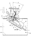
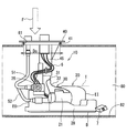
- FIG. 2 is a plan view of the fuel supply device of FIG.
- FIG. 2 is a rear view of the fuel supply device of FIG.
- It is an enlarged view of the insertion guide member in the fuel supply apparatus of FIG.
- FIG. 6 is a view in the direction of arrow VI in FIG. 5.
- FIG. 8 is a cross-sectional view taken along line VIII-VIII (guide portion orthogonal plane Sx) of FIG.
- It is a figure of the attachment stage 3 and the removal stage 1 in a method same as the above.
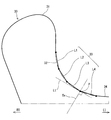
- It is an enlarged view of the guide part of 2nd Embodiment.
- the fuel supply device of this embodiment is a device that is attached to, for example, a fuel tank mounted on a vehicle and supplies fuel in the fuel tank to a high-pressure pump.
- the high-pressure fuel boosted by the high-pressure pump is injected from the fuel injection valve into the engine cylinder and the intake passage.
- the configuration of the fuel supply device alone that is, the configuration of the fuel supply device before being attached to the fuel tank will be described mainly with reference to FIGS.
- the reference numerals shown in FIGS. 5 to 10 are used for the reference numerals of the fuel tank, the opening, and the like.
- the fuel supply device 10 of the first embodiment includes a pump unit 20, a flange 40, a support column 45, a connecting shaft 48, connecting pipes 51 and 52, a wire harness 6, a sender gauge 7, and the like.
- the upper side in FIGS. 1 to 3 is described as the upper side, and the lower side is described as the lower side.
- the pump unit 20 has a substantially rectangular parallelepiped shape with the base portion 28 as the lower surface B, and the longitudinal direction of the substantially rectangular parallelepiped is defined as the “longitudinal direction of the pump unit 20”. 1 to 3, the center line CL indicates the approximate center in the longitudinal direction. Moreover, let the virtual plane parallel to the lower surface B be the top surface T in the part where the height from the lower surface B is the largest except the insertion guide member 30 mentioned later.
- the substantially cylindrical fuel pump 21 is placed on the base portion 28 so that the cylinder axis is along the longitudinal direction of the pump unit 20.
- the fuel pump 21 pressurizes the fuel sucked from the suction flow path 22 provided on one side in the longitudinal direction, and discharges it from the discharge flow path 23 provided on the other side in the longitudinal direction.
- the side end on the suction flow path 22 side in the longitudinal direction of the pump unit 20 is referred to as “suction side end EI”, and the side end on the discharge flow path 23 side in the longitudinal direction of the pump unit 20 is “discharge”.
- Side end EO “.
- a sender gauge 7 is connected to the suction side end EI of the pump unit 20 via a gauge arm 75.
- the sender gauge 7 detects the liquid level of the fuel in a state where the pump unit 20 is installed in the fuel tank 80.
- the sender gauge 7 can be rotated as indicated by a broken line in FIG. 1 by buoyancy generated in the float portion in accordance with the height of the liquid level.
- a relief valve 25 for adjusting the discharge pressure of the fuel pump 21 is provided at the discharge side end EO of the pump unit 20.
- the adjustment of the pressure by the relief valve 25 includes a case where only the upper limit pressure is restricted and a case where the pressure is adjusted within the upper and lower limits.
- the discharge connecting pipe 51 forms a fuel passage from the relief valve 25 to the discharge port 42 provided in the flange 40.
- the return connection pipe 52 forms a fuel passage for return from the relief valve 25.
- the fuel for the specified pressure out of the fuel discharged by the fuel pump 21 is pumped to the discharge port 42 via the discharge connection pipe 51.
- the fuel for the excess pressure is returned to the discharge flow path 23 via the return connection pipe 52 as indicated by the broken line arrow fr.
- the flange 40 can be engaged with the opening 81 of the fuel tank 80, and for example, a fitting portion 41 formed in an annular shape is fitted into the inner diameter of the opening 81. That is, the fitting portion diameter Df corresponds to the opening inner diameter Do of the fuel tank 80.
- the fitting part 41 does not need to be a perfect cyclic
- the support column 45 is fixed to the flange 40 and extends from the flange 40 toward the pump unit 20. As shown in FIG. 3, the end of the column 45 opposite to the flange 40 and the pump unit 20 are connected so as to be relatively rotatable.
- the connecting shaft 48 is configured by fitting a shaft portion provided on one side of the pump unit 20 or the support column 45 into a hole provided on the other side of the pump unit 20 or the support column 45. In the present embodiment, the connecting shaft 48 is provided on the discharge side end EO side with respect to the center CL in the longitudinal direction of the pump unit 20.
- the flange 40 is disposed above the pump unit 20 via an upright support 45.
- the support column 45 is inclined most toward the discharge side end EO side, and the height difference between the flange 40 and the pump unit 20 is minimized.
- the state shown in FIG. 1 is called the “upright state” of the column 45, and the state shown in FIGS. 2 and 3 is called the “maximum tilt state” of the column 45.
- the inclination angle in the maximum inclination state based on the upright state is represented as the maximum inclination angle ⁇ m.
- the support column 45 In the upright state, the support column 45 stands upright with respect to the base portion 28 of the pump unit 20, and the flange 40 is farthest from the base portion 28. At this time, the flange 40 is parallel to the lower surface B of the base portion 28. In the maximum inclination state, the support column 45 is closest to the base portion 28 of the pump unit 20.
- pillar 45 can be rotationally moved between an upright state and a maximum inclination state.
- a virtual plane on which the support column 45 rotates is defined as a “rotation plane of the support column 45”.
- the longitudinal direction of the pump unit 20 is substantially parallel to the rotation plane of the support column 45.
- the wire harness 6 is routed along the support column 45 from the connector 44 provided on the flange 40.
- the wire harness 6 receives signals such as a drive signal of the fuel pump 21 input from an external control device and a detection signal of the remaining fuel amount by the sender gauge 7.
- the clamp unit 46 provided on the support column 45 holds the portion arranged on the support column 45 side, and the clamp units 35 and 36 provided on the pump unit 20 (see FIGS. 3 and 4). ) Etc., the part wired by the pump unit 20 side is hold
- the portion of the wire harness 6 routed to the support 45 side rotates together with the support 45. Further, an intermediate portion between the portion arranged on the support column 45 side and the portion arranged on the pump unit 20 side is arranged with a degree of freedom so as to follow the rotational movement of the support column 45.
- An insertion guide member 30 is provided above the fuel pump 21 of the pump unit 20 and has a plate shape extending in the longitudinal direction.
- the insertion guide member 30 is used for guidance when the pump unit 20 is inserted into the opening 81 of the fuel tank 80. Yes.
- the insertion guide member 30 is not limited to an independent member, and may be formed integrally with other parts of the pump unit 20.
- the insertion guide member 30 includes a stopper portion 31, a guide portion 32, and an extending portion in order from the discharge side end portion EO side to the suction side end portion EI side along the upper edge, that is, the edge opposite to the base portion 28. 34.
- the stopper portion 31 protrudes to a position higher than the top surface T on the discharge side end EO side.
- the extending portion 34 gently rises from the suction side end EI side toward the discharge side end EO side at a position lower than the top surface T.
- the guide part 32 is adjacent to the stopper part 31 and connects between the stopper part 31 and the extending part 34.
- the outline of the guide portion 32 is a curved line.
- the guide unit 32 guides the pump unit 20 in the rotation direction with respect to the support column 45.
- FIG. 6 in which the projection surface obtained by projecting the pump unit 20 in the longitudinal direction is viewed from the suction side end EI side, a two-dot chain line circle corresponds to the opening inner diameter Do of the fuel tank 80 or the opening inner diameter Do.
- the virtual circle of the fitting part diameter Df of the flange 40 is shown.
- the stopper portion 31 protrudes from a virtual circle having a fitting portion diameter Df.
- a virtual plane passing through the point P while being orthogonal to the tangent Lt at the point P on the guide portion 32 and intersecting the base portion 28 at the maximum inclination angle ⁇ m is referred to as “guide portion orthogonal plane Sx. Is defined.
- FIG. 8 which shows the cross section of the pump unit 20 in the guide part orthogonal plane Sx, the cross section of the pump unit 20 is contained in the virtual circle of the fitting part diameter Df.
- the operator uses the guide function of the guide portion 32 to bring the guide portion 32 into contact with the edge of the opening portion 81, while following the curved guide shape. Can be smoothly rotated with respect to the support 45.
- the insertion guide member 30 of the present embodiment has a stopper function by the stopper portion 31 and a guide function by the guide portion 32. With these functions, workability of the work of attaching the fuel supply device 10 to the fuel tank 80 and the work of removing it from the fuel tank 80 is improved. Details of the working method will be described later.
- the guide portion 32 is provided on the connecting shaft 48 side with respect to the center CL in the longitudinal direction of the pump unit 20.
- the support column 45 is inclined more toward the base portion 28 than the guide portion 32 in the maximum inclined state. Accordingly, at least a portion of the wire harness 6 that rotates together with the support column 45 is routed closer to the base portion 28 than the guide portion 32 of the insertion guide member 30 in the maximum inclined state.
- the relief valve 25 is disposed on the opposite side of the guide portion 32 with respect to the stopper portion 31 of the insertion guide member 30. In other words, in the maximum inclination state of the support column 45, the relief valve 25 is disposed on the flange 40 side with respect to the guide portion orthogonal plane Sx.
- At least a part of the discharge connecting pipe 51 and the return connecting pipe 52 passes through the side opposite to the center CL in the longitudinal direction of the pump unit 20 with respect to the guide portion 32.
- at least a part of the connection pipes 51 and 52 is disposed on the flange 40 side with respect to the guide part orthogonal plane Sx.
- FIG. 5 and FIG. 6 Please refer to FIG. 5 and FIG.
- the operator inserts the pump unit 20 in the vertical direction from the opening 81 in a posture in which the support 45 is in the maximum inclined state and the suction side end EI in the longitudinal direction of the pump unit 20 faces downward.
- FIG. 6 since the stopper portion 31 of the insertion guide member 30 protrudes from a virtual circle having the opening inner diameter Do, vertical insertion is restricted at a position where the stopper portion 31 abuts against the edge of the opening 81. Is done.
- a clearance between the sender gauge 7 and the bottom surface of the fuel tank 80 (hereinafter referred to as “tank bottom surface” as appropriate) 82 is secured. Further, a clearance between the sender gauge 7 and the fuel tank inner wall surface in the front-rear direction of the paper surface of FIG. 5 is also ensured.
- ⁇ Installation stage 2> Please refer to FIG. 7 and FIG. Following the attachment stage 1, the operator brings the guide portion 32 of the insertion guide member 30 into contact with the edge of the opening portion 81, and the entire fuel supply device 10 so as to level the flange 40 along the guide portion 32. Is rotated in the direction of the arrow Up. As shown in FIG. 8, the cross section of the pump unit 20 in the guide portion orthogonal plane Sx is formed so as to be within a virtual circle having the opening inner diameter Do, that is, through the opening 81.
- the guide portion 32 ensures a clearance between the sender gauge 7 and the tank bottom surface 82 and the inner wall surface.
- ⁇ Installation stage 3> Please refer to FIG. From the state of the attachment stage 2, the operator applies a load F downward in the vertical direction with respect to the flange 40 and the column 45 while bringing the guide portion 32 into contact with the edge of the opening portion 81 as shown in the G portion. Then, by the guide function of the guide portion 32, the pump unit 20 rotates with respect to the support column 45 in the direction in which the longitudinal direction is horizontal, that is, the direction in which the base portion 28 faces the tank bottom surface 82. Along with this, the inclination angle ⁇ of the support column 45 gradually decreases.
- the guide portion 32 ensures a clearance between the sender gauge 7 and the tank bottom surface 82 and the inner wall surface.
- the pump unit 20 When the installation of the fuel supply device 10 is completed, the pump unit 20 is horizontal in the longitudinal direction, and the base portion 28 is disposed along the tank bottom surface 82. Moreover, the support
- the removal method of the fuel supply device 10 is basically performed by reversing the steps of the attachment method, and reference is again made to FIGS. 9, 7 and 5 referred to in the attachment step.
- the R portion indicating the return connecting pipe 52 particularly indicates a portion to be noted at the removal stage.
- ⁇ Removal stage 3> Please refer to FIG. Following the removal stage 2, the operator rotates the entire fuel supply device 10 so that the longitudinal direction of the pump unit 20 is in the vertical direction with the column 45 in the maximum inclined state. When the guide portion 32 leaves the edge of the opening 81, the operator pulls up the pump unit 20 in the vertical direction. Even at this stage, the operator can grasp the return connection pipe 52 shown in the R portion as a handle.
- the operator preferably rotates the pump unit 20 in the fuel tank 80 while bringing the guide portion 32 into contact with the edge of the opening portion 81. Can be made. Further, the sender gauge 7 is prevented from coming into contact with the tank bottom surface 82 and being damaged when the fuel supply device 10 is inserted. Furthermore, at the time of removal, the operator can grasp the return connection pipe 52 provided at the discharge side end in the longitudinal direction of the pump unit 20. Therefore, workability is improved.
- effect The effects of the fuel supply device 10 of the present embodiment will be described corresponding to the description of the claims.
- the number in parentheses of each item indicates the number of the claim.
- the effect (2) is described as the effect of the first embodiment.
- the insertion guide member 30 provided in the pump unit 20 has a stopper portion 31 and a guide portion 32.
- the stopper portion 31 is moved. Insertion is restricted at a position in contact with the edge of the opening 81. Subsequently, the operator can suitably rotate the pump unit 20 in the direction in which the base portion 28 faces the tank bottom surface 82 while bringing the guide portion 32 into contact with the edge of the opening portion 81.
- the components of the pump unit 20 interfere with the bottom surface and the inner wall surface of the fuel tank 80 and are damaged. Can be prevented.
- the operator preferably rotates the pump unit 20 in the direction in which the pump unit 20 is raised from the tank bottom surface 82 while bringing the guide portion 32 into contact with the edge of the opening 81. be able to.
- the workability of the attachment and detachment work of the fuel supply device 10 can be improved.
- the outline of the guide portion 32 is a curved line.
- the pump unit 20 can be smoothly guided while the guide portion 32 is brought into contact with the edge of the opening 81.
- the relief valve 25 is disposed on the opposite side of the guide portion 32 with respect to the stopper portion 31 of the insertion guide member 30.
- the support column 45 is inclined to the base portion 28 side of the pump unit 20 from the guide portion 32 in the maximum inclination state.
- the guide portion 32 comes into contact with the edge of the opening portion 81 before the support column 45, and the guide function can be exhibited.
- the guide portion 32 is provided on the connection shaft 48 side with respect to the center CL in the longitudinal direction of the pump unit 20.
- the moment when the pump unit 20 is rotated along the guide portion 32 can be reduced by arranging the guide portion 32 near the connecting shaft 48.
- connection pipes 51 and 52 forming the fuel passage is opposite to the center CL in the longitudinal direction of the pump unit 20 with respect to the guide portion 32 of the insertion guide member 30, that is, The discharge side end EO side passes through the guide part 32.
- the operator can pull up the pump unit 20 by grasping the connecting pipes 51 and 52. Workability is improved.
- the sender gauge 7 is disposed between the bottom surface 82 and the inner side surface of the fuel tank 80 in a state where the fuel tank 80 is installed horizontally and the guide portion 32 is in contact with the opening 81. Arranged to ensure clearance.
- the effects of the method of attaching the fuel supply device 10 of the present embodiment to the fuel tank 80 and the method of removing it from the fuel tank 80 are the same as the effect (1) described above.
- Patent Document 1 Japanese Patent Laid-Open No. 2016-44643
- the base part of the pump unit needs to be enlarged in order to function as a protective part of the float, and can be freely mounted on the fuel tank.
- the degree was limited.
- this embodiment without damaging the pump unit, it is possible to prevent parts from being damaged at the time of attaching to the fuel tank, and to improve the attaching / detaching workability.
- FIG. 11 A second embodiment relating to the shape of the guide portion of the insertion guide member 30 will be described with reference to FIG.
- a solid line shows the outline shape of the guide part 33 of 2nd Embodiment
- a dashed-two dotted line shows the outline shape of the guide part 32 of 1st Embodiment shown in FIG.
- the contour shape of the guide portion 32 of the first embodiment is a curved line
- the contour shape of the guide portion 33 of the second embodiment is that of a plurality of straight lines L1, L2, L3, and L4 whose inclination changes continuously. Composed of a combination.
- the plurality of straight lines L1, L2, L3, and L4 are defined by performing linear interpolation between adjacent points on a two-dot chain line curve.
- tangent line Lt of the point P for defining the guide part orthogonal plane Sx may be defined in the same manner as in the first embodiment as a tangent line of a curve that smoothly connects a plurality of straight line break points.
- the operator when the guide unit 33 of the second embodiment is used, when the pump unit 20 is inserted into the fuel tank 80, the operator inserts while changing the insertion angle step by step as the linear portion to be guided moves. To do. Therefore, as an effect (3) of the second embodiment that replaces the effect (2) of the first embodiment, the operator can grasp the insertion degree sensuously according to the stage.
- the second embodiment has the same operational effects as the first embodiment.
- the longitudinal direction of the pump unit 20 is parallel to the rotation plane of the support column 45.
- the longitudinal direction of the pump unit is not strictly parallel to the rotation plane of the support column and may be slightly inclined.
- the pump unit is formed such that the direction along the rotation plane of the support column is the longitudinal direction” is not limited to the positional relationship between the pump unit and the rotation plane of the support column being parallel. , "Direction along” is broadly interpreted.
- the fuel supply device may not include a member other than the base portion, the fuel pump, and the insertion guide member, for example, the relief valve or the wire harness described in the above embodiment, as a component of the pump unit. Further, the fuel supply device may not include a sender gauge.
- FIG. 6 is a projection view in the longitudinal direction of the pump unit 20
- the stopper portion 31 of the insertion guide member 30 protrudes from the virtual circle having the opening inner diameter Do. The case is assumed.
- the entire portion of the insertion guide member 30 is contained in a virtual circle having the opening inner diameter Do and there is substantially no protruding portion that functions as a stopper portion. Even in such a case, the operator rotates the pump unit 20 by the guide function by bringing the fuel supply device 10 to one side of the opening 81 and bringing the guide 32 into contact with the edge of the opening 81. be able to.
- the “method for attaching and detaching the fuel supply device” of the present disclosure includes such a method.
- the fuel supply device is not limited to the one mounted on the vehicle, but may be used for a vehicle other than a vehicle such as an airplane or a ship.
- this indication is not limited to the said embodiment at all, In the range which does not deviate from the meaning of this indication, it can implement with a various form.
Landscapes
- Engineering & Computer Science (AREA)
- Chemical & Material Sciences (AREA)
- Combustion & Propulsion (AREA)
- Mechanical Engineering (AREA)
- General Engineering & Computer Science (AREA)
- Life Sciences & Earth Sciences (AREA)
- Sustainable Development (AREA)
- Sustainable Energy (AREA)
- Transportation (AREA)
- Cooling, Air Intake And Gas Exhaust, And Fuel Tank Arrangements In Propulsion Units (AREA)
Abstract
燃料供給装置(10)の支柱(45)は、ポンプユニット(20)と相対的に回転可能に連結されている。ポンプユニット(20)は、支柱(45)の回転平面に沿った方向が長手方向となるように形成されており、且つ、長手方向に延び燃料タンクの開口部へ挿入される時の案内に用いられる挿入ガイド部材(30)を含む。挿入ガイド部材(30)は、ベース部(28)とは反対側の縁に沿って、ストッパ部(31)及びガイド部(32)を有する。ストッパ部(31)は、ポンプユニット(20)を長手方向に投影した投影面において、嵌合部直径(Df)の仮想円から突出する。ガイド部(32)は、ポンプユニット(20)を支柱(45)に対する回転方向に案内する。ガイド部直交平面(Sx)におけるポンプユニット(20)の断面は、嵌合部直径(Df)の仮想円内に収まるように形成されている。
Description
本願は、2016年11月18日に出願された日本国特許出願第2016-224865号に基づくものであり、この開示をもってその内容を本明細書中に開示したものとする。
本開示は、燃料タンク内に取り付けられる燃料供給装置、並びに、燃料供給装置の取り付け及び取り外し方法に関する。
従来、燃料タンク内に取り付けられる燃料供給装置において、取り付け作業時に部品が燃料タンクに衝突して破損することを防止する技術が知られている。例えば特許文献1に開示された燃料供給装置は、燃料タンクへの取り付け作業時の姿勢で、燃料残量検出装置のフロートがポンプユニットのベース部の下端よりも上方に位置する。燃料タンクへの取り付け時に、ベース部の下端が先にタンク底面に当接し保護部として機能することにより、フロートがタンク底面に当接することが回避される。
特許文献1の技術では、フロートの保護部として機能させるため、ポンプユニットのベース部を大型化する必要があり、燃料タンクへの搭載自由度が制限されるという問題があった。また、特許文献1には、燃料タンクから燃料供給装置を取り外す時の作業性について何ら言及されていない。
本開示は上述の課題に鑑みてなされたものであり、その目的は、ポンプユニットを大型化させることなく、燃料タンクへの取り付け作業時における部品破損を防止し、且つ、取り付け及び取り外し作業性を向上させる燃料供給装置を提供することにある。
本開示では、燃料タンク内に取り付けられる燃料供給装置を提供する。この燃料供給装置は、フランジと、ポンプユニットと、支柱と、連結軸と、を備える。
フランジは、燃料タンクの開口部に係合可能であり、開口部の内径に相当する嵌合部直径を有する。ポンプユニットは、ベース部、及び、ベース部に載置された燃料ポンプを含む。支柱は、フランジに固定されている。連結軸は、支柱とポンプユニットとを相対的に回転可能に連結する。
支柱は、「ポンプユニットのベース部に対して直立し、フランジがベース部から最も離れる直立状態」と、「ポンプユニットのベース部に対して最も接近する最大傾斜状態」との間を回転移動可能である。
ポンプユニットは、支柱の回転平面に沿った方向が長手方向となるように形成されており、且つ、当該長手方向に延び燃料タンクの開口部へ挿入される時の案内に用いられる挿入ガイド部材をさらに含む。
挿入ガイド部材は、ベース部とは反対側の縁に沿って、ストッパ部及びガイド部を有する。
ストッパ部は、ポンプユニットを長手方向に投影した投影面において、嵌合部直径の仮想円から突出する。ガイド部は、ポンプユニットを支柱に対する回転方向に案内する。
ここで、ガイド部上の点における接線と直交しつつ当該点を通り、且つ、ベース部に対し支柱の最大傾斜状態での傾斜角度で交わる仮想平面を「ガイド部直交平面」と定義する。このガイド部直交平面におけるポンプユニットの断面は、嵌合部直径の仮想円内に収まるように形成されている。
燃料供給装置を燃料タンクに取り付ける作業において、作業者は、支柱の最大傾斜状態でポンプユニットを開口部の開口面に対し垂直方向に挿入していくと、ストッパ部が開口部の縁に当接した位置で挿入が規制される。それに続き作業者は、ガイド部を開口部の縁に当接させながら、ポンプユニットを、ベース部が燃料タンクの底面に対向する方向に好適に回転させることができる。
また、このとき、作業者が燃料タンクの底面を視認することが困難な状況であっても、ポンプユニットの構成部品が燃料タンクの底面や内壁面に干渉して破損することを防止することができる。
例えば、燃料の液面高さを検知するセンダゲージは、ガイド部が開口部の縁に当接している状態で燃料タンクの底面及び内壁面との間にクリアランスを確保するように配置されることが好ましい。
さらに、燃料供給装置を燃料タンクから取り外す作業においても、作業者は、ガイド部を開口部の縁に当接させながら、ポンプユニットをタンク底面から起こす方向に好適に回転させることができる。
よって、本開示では、燃料供給装置の取り付け及び取り外し作業の作業性を向上させることができる。
さらに、本開示では、燃料供給装置の取り付け及び取り外し方法を提供する。
ここで、ポンプユニットの長手方向に投影した投影面において、燃料タンクの開口部の内径に対し挿入ガイド部材が突出しない場合、すなわち、挿入ガイド部材の端部がストッパ部として機能しない場合でも、本開示の取り付け及び取り外し方法は適用可能である。
つまり、作業者は、燃料供給装置を開口部の一方側に寄せてガイド部を開口部の縁に当接させることで、ガイド機能によりポンプユニットを回転動作させることができ、上述の燃料供給装置における作用効果と同様の作用効果を得ることができる。
本開示についての上記目的およびその他の目的、特徴や利点は、添付の図面を参照しながら下記の詳細な記述により、より明確になる。
以下、燃料供給装置の実施形態を図面に基づいて説明する。本実施形態の燃料供給装置は、例えば車両に搭載された燃料タンクに取り付けられ、燃料タンクの燃料を高圧ポンプへ供給する装置である。高圧ポンプで昇圧された高圧燃料は、燃料噴射弁からエンジンの気筒や吸気通路へ噴射される。
(第1実施形態)
第1実施形態の燃料供給装置について、図1~図10を参照して説明する。なお、後述の第2実施形態は、第1実施形態に対し、ポンプユニットに設けられた挿入ガイド部材のガイド部形状が異なるのみであり、大部分の説明は第1実施形態と共通する。
第1実施形態の燃料供給装置について、図1~図10を参照して説明する。なお、後述の第2実施形態は、第1実施形態に対し、ポンプユニットに設けられた挿入ガイド部材のガイド部形状が異なるのみであり、大部分の説明は第1実施形態と共通する。
最初に、主に図1~図3を参照し、燃料供給装置単体での構成、すなわち、燃料タンクに取り付けられる前の燃料供給装置の構成について説明する。なお、この部分の説明で、燃料タンク、開口部等の符号は、図5~図10に記載された符号を援用する。
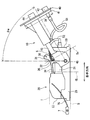
図1~図3に示すように、第1実施形態の燃料供給装置10は、ポンプユニット20、フランジ40、支柱45、連結軸48、接続管51、52、ワイヤハーネス6、センダゲージ7等を備える。以下、図1~図3における上側を上、下側を下として記載する。
ポンプユニット20は、全体シルエットが、ベース部28を下面Bとする略直方体状を呈しており、この略直方体の長手方向を「ポンプユニット20の長手方向」と定義する。図1~図3において、中心線CLは、長手方向の概略の中心を示す。また、後述する挿入ガイド部材30を除いて下面Bからの高さが最大である部分における、下面Bと平行な仮想平面を頂面Tとする。
略円筒状の燃料ポンプ21は、円筒の軸がポンプユニット20の長手方向に沿うようにベース部28上に載置されている。燃料ポンプ21は、長手方向の一方側に設けられた吸入流路22から吸入した燃料を加圧し、長手方向の他方側に設けられた吐出流路23から吐出する。これに対応し、ポンプユニット20の長手方向における吸入流路22側の側端部を「吸入側端部EI」とし、ポンプユニット20の長手方向における吐出流路23側の側端部を「吐出側端部EO」とする。
ポンプユニット20の吸入側端部EIには、ゲージアーム75を介してセンダゲージ7が接続されている。センダゲージ7は、ポンプユニット20が燃料タンク80内に設置された状態で燃料の液面高さを検知する。センダゲージ7は、液面の高さに応じてフロート部に生ずる浮力により、図1に破線で示すように回動可能である。
ポンプユニット20の吐出側端部EOには、燃料ポンプ21の吐出圧力を調整するリリーフバルブ25が設けられている。リリーフバルブ25による圧力の調整には、上限圧力のみを制限する場合と、上下限範囲内に調整する場合とが含まれる。
吐出接続管51は、リリーフバルブ25からフランジ40に設けられた吐出ポート42への燃料通路を形成する。リターン接続管52は、リリーフバルブ25からのリターン用の燃料通路を形成する。
実線矢印foで示すように、燃料ポンプ21が吐出した燃料のうち、規定圧力分の燃料は、吐出接続管51を経由して吐出ポート42に圧送される。過剰圧力分の燃料は、破線矢印frで示すように、リターン接続管52を介して吐出流路23に戻される。
フランジ40は、燃料タンク80の開口部81に係合可能であり、例えば環状に形成された嵌合部41が開口部81の内径に嵌合する。すなわち、嵌合部直径Dfは、燃料タンク80の開口部内径Doに相当する。なお、嵌合部41は完全な環状である必要はなく、複数の円弧部が断続的に設けられてもよい。その場合、円弧部の合計長さは、円周の2分の1以上であることが好ましい。
支柱45は、フランジ40に固定され、フランジ40からポンプユニット20に向かって延びている。図3に示すように、支柱45のフランジ40とは反対側の端部と、ポンプユニット20とを相対的に回転可能に連結する。連結軸48は、ポンプユニット20又は支柱45の一方に設けられた軸部が、ポンプユニット20又は支柱45の他方に設けられた孔に嵌合することにより構成される。本実施形態では、連結軸48は、ポンプユニット20の長手方向の中心CLに対し、吐出側端部EO側に設けられている。
図1に示す状態では、フランジ40は、直立した支柱45を介してポンプユニット20の上方に配置されている。図2、図3に示す状態では、支柱45が吐出側端部EO側に最も傾斜し、フランジ40とポンプユニット20との高低差が最小となっている。
図1に示す状態を支柱45の「直立状態」といい、図2、図3に示す状態を支柱45の「最大傾斜状態」という。直立状態を基準とする最大傾斜状態での傾斜角度を最大傾斜角度θmと表す。
直立状態では、支柱45は、ポンプユニット20のベース部28に対して直立し、フランジ40がベース部28から最も離れる。このとき、フランジ40は、ベース部28の下面Bに対し平行となる。最大傾斜状態では、支柱45がポンプユニット20のベース部28に最も接近する。支柱45は、直立状態と最大傾斜状態との間を回転移動可能である。
ここで、支柱45が回転移動する仮想平面を「支柱45の回転平面」と定義する。本実施形態では、ポンプユニット20の長手方向は支柱45の回転平面に対し略平行である。
また、フランジ40に設けられたコネクタ44から支柱45に沿ってワイヤハーネス6が配索されている。ワイヤハーネス6は、外部の制御装置から入力される燃料ポンプ21の駆動信号や、センダゲージ7による燃料残量の検出信号等の信号が伝送される。
ワイヤハーネス6は、支柱45に設けられたクランプ部46により、支柱45側に配索された部分が保持されるとともに、ポンプユニット20に設けられたクランプ部35、36(図3、図4参照)等により、ポンプユニット20側に配索された部分が保持される。支柱45側に配索された部分のワイヤハーネス6は、支柱45と共に回転する。また、支柱45側に配索された部分とポンプユニット20側に配索された部分との中間部分は、支柱45の回転移動に追従可能なように自由度を持って配索される。
なお、図2には、ワイヤハーネス6の図示を省略する。
次に、図1~図3に加えて、図4、図6、図8を参照する。ポンプユニット20の燃料ポンプ21の上方には、長手方向に延びる板状を呈し、ポンプユニット20が燃料タンク80の開口部81へ挿入される時の案内に用いられる挿入ガイド部材30が設けられている。挿入ガイド部材30は、独立した部材とは限らず、ポンプユニット20の他の部分と一体に形成されてもよい。
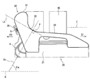
挿入ガイド部材30は、上縁、すなわちベース部28とは反対側の縁に沿って、吐出側端部EO側から吸入側端部EI側に向かう順に、ストッパ部31、ガイド部32及び延伸部34を有している。
ストッパ部31は、吐出側端部EO側において頂面Tよりも高い位置に突出している。
延伸部34は、頂面Tよりも低い位置で吸入側端部EI側から吐出側端部EO側に向かって緩やかに上昇している。
ガイド部32は、ストッパ部31に隣接し、ストッパ部31と延伸部34との間を接続している。特に第1実施形態では、ガイド部32の輪郭は、曲線からなっている。ガイド部32は、ポンプユニット20を支柱45に対する回転方向に案内する。
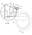
ポンプユニット20を長手方向に投影した投影面を吸入側端部EI側から視た図6において、二点鎖線の円は、燃料タンク80の開口部内径Do、又は、開口部内径Doに相当するフランジ40の嵌合部直径Dfの仮想円を示す。図6のSt部に示すように、ストッパ部31は、嵌合部直径Dfの仮想円から突出している。
このことは、ポンプユニット20を長手方向に移動させたとき、ストッパ部31が開口部81の縁に干渉し、ストッパ機能を果たすことを意味する。
また、図4に示すように、ガイド部32上の点Pにおける接線Ltと直交しつつ点Pを通り、且つ、ベース部28に対し最大傾斜角度θmで交わる仮想平面を「ガイド部直交平面Sx」と定義する。ガイド部直交平面Sxにおけるポンプユニット20の断面を示す図8において、ポンプユニット20の断面は、嵌合部直径Dfの仮想円内に収まっている。
このことは、ガイド部直交平面Sxが燃料タンク80の開口部81の開口面Soに一致するようにポンプユニット20を傾けた姿勢で、ポンプユニット20の断面部分が開口部81を通過可能であることを意味する。
燃料供給装置10を燃料タンク80に取り付ける作業において作業者は、ガイド部32のガイド機能により、ガイド部32を開口部81の縁に当接させながら、曲線のガイド形状に沿って、ポンプユニット20を支柱45に対して滑らかに回転させることができる。
このように本実施形態の挿入ガイド部材30は、ストッパ部31によるストッパ機能、及びガイド部32によるガイド機能を有する。これらの機能により、燃料供給装置10を燃料タンク80に取り付ける作業、及び、燃料タンク80から取り外す作業の作業性が向上する。その作業方法の詳細は後述する。
挿入ガイド部材30のガイド部32と他の部材との位置関係について補足する。
図3に示すように、ガイド部32は、ポンプユニット20の長手方向の中心CLに対して連結軸48側に設けられている。
支柱45は、最大傾斜状態において、ガイド部32よりもベース部28側に傾斜している。これに伴い、ワイヤハーネス6のうち少なくとも支柱45と共に回転する部分は、最大傾斜状態において、挿入ガイド部材30のガイド部32よりもベース部28側に配索されている。
リリーフバルブ25は、挿入ガイド部材30のストッパ部31に対しガイド部32とは反対側に配置されている。言い換えれば、支柱45の最大傾斜状態において、リリーフバルブ25は、ガイド部直交平面Sxに対しフランジ40側に配置されている。
吐出接続管51及びリターン接続管52は、少なくとも一部が、ガイド部32に対してポンプユニット20の長手方向の中心CLとは反対側を通っている。言い換えれば、支柱45の最大傾斜状態において、接続管51、52は、少なくとも一部がガイド部直交平面Sxに対しフランジ40側に配置されている。
[燃料供給装置の取り付け及び取り外し方法]
次に、本実施形態の燃料供給装置10を燃料タンク80に取り付ける方法、及び、燃料タンク80から取り外す方法について図5~図10を参照して説明する。この説明では、便宜上、燃料タンク80の開口部81側を上、底面82側を下として記載する。また、開口部81の開口面So及び底面82は水平に配置されているものとし、開口面Soに直交する方向を「垂直方向」という。図5、図9、図10における垂直方向の実線ブロック矢印は、取り付け作業時の荷重Fの方向を示す。
次に、本実施形態の燃料供給装置10を燃料タンク80に取り付ける方法、及び、燃料タンク80から取り外す方法について図5~図10を参照して説明する。この説明では、便宜上、燃料タンク80の開口部81側を上、底面82側を下として記載する。また、開口部81の開口面So及び底面82は水平に配置されているものとし、開口面Soに直交する方向を「垂直方向」という。図5、図9、図10における垂直方向の実線ブロック矢印は、取り付け作業時の荷重Fの方向を示す。
<取り付け段階1>
図5、図6を参照する。支柱45を最大傾斜状態とし、ポンプユニット20の長手方向の吸入側端部EIを下に向けた姿勢で、作業者は、ポンプユニット20を開口部81から垂直方向に挿入する。図6に示すように、挿入ガイド部材30のストッパ部31は開口部内径Doの仮想円から突出しているため、ストッパ部31が開口部81の縁に当接した位置で垂直方向の挿入が規制される。
図5、図6を参照する。支柱45を最大傾斜状態とし、ポンプユニット20の長手方向の吸入側端部EIを下に向けた姿勢で、作業者は、ポンプユニット20を開口部81から垂直方向に挿入する。図6に示すように、挿入ガイド部材30のストッパ部31は開口部内径Doの仮想円から突出しているため、ストッパ部31が開口部81の縁に当接した位置で垂直方向の挿入が規制される。
このとき、Sg部に示すように、センダゲージ7と燃料タンク80の底面(以下、適宜「タンク底面」)82との間のクリアランスが確保される。また、図5の紙面前後方向におけるセンダゲージ7と燃料タンク内壁面との間のクリアランスも確保される。
<取り付け段階2>
図7、図8を参照する。取り付け段階1に続き、作業者は、挿入ガイド部材30のガイド部32を開口部81の縁に当接させ、ガイド部32に沿って、フランジ40を水平にするように燃料供給装置10の全体を矢印Upの方向に回転させる。図8に示すように、ガイド部直交平面Sxにおけるポンプユニット20の断面は、開口部内径Doの仮想円内に収まるように、すなわち開口部81を通過可能なように形成されている。
図7、図8を参照する。取り付け段階1に続き、作業者は、挿入ガイド部材30のガイド部32を開口部81の縁に当接させ、ガイド部32に沿って、フランジ40を水平にするように燃料供給装置10の全体を矢印Upの方向に回転させる。図8に示すように、ガイド部直交平面Sxにおけるポンプユニット20の断面は、開口部内径Doの仮想円内に収まるように、すなわち開口部81を通過可能なように形成されている。
このときも、Sg部に示すように、ガイド部32によってセンダゲージ7とタンク底面82及び内壁面との間のクリアランスが確保される。
<取り付け段階3>
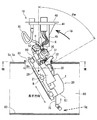
図9を参照する。取り付け段階2の状態から作業者は、G部に示すようにガイド部32を開口部81の縁に当接させながら、フランジ40及び支柱45に対し垂直方向下方に荷重Fを加える。すると、ガイド部32のガイド機能により、ポンプユニット20が支柱45に対し、長手方向が水平となる方向、すなわちベース部28がタンク底面82と対向する方向に回転する。これに伴い、支柱45の傾斜角度θが次第に小さくなる。
図9を参照する。取り付け段階2の状態から作業者は、G部に示すようにガイド部32を開口部81の縁に当接させながら、フランジ40及び支柱45に対し垂直方向下方に荷重Fを加える。すると、ガイド部32のガイド機能により、ポンプユニット20が支柱45に対し、長手方向が水平となる方向、すなわちベース部28がタンク底面82と対向する方向に回転する。これに伴い、支柱45の傾斜角度θが次第に小さくなる。
このときも、Sg部に示すように、ガイド部32によってセンダゲージ7とタンク底面82及び内壁面との間のクリアランスが確保される。
<取り付け完了段階>
図10を参照する。取り付け段階3の後、作業者は、さらにフランジ40の嵌合部41が開口部81に嵌合する位置まで燃料供給装置10を燃料タンク80に挿入する。
図10を参照する。取り付け段階3の後、作業者は、さらにフランジ40の嵌合部41が開口部81に嵌合する位置まで燃料供給装置10を燃料タンク80に挿入する。
燃料供給装置10の取り付けが完了したとき、ポンプユニット20は長手方向が水平となり、ベース部28がタンク底面82に沿って配置される。また、支柱45は、傾斜角度θが0の直立状態となる。
燃料供給装置10の取り外し方法は、基本的に取り付け方法の各段階を逆に進めることにより行われるものであり、取り付け段階で参照した図9、図7、図5を再び参照する。図7、図5においてリターン接続管52を指すR部は、特に取り外し段階で注目する箇所を示す。
<取り外し段階1>
図9を参照する。作業者は、G部に示すように、挿入ガイド部材30のガイド部32が開口部81の縁に当接するまでフランジ40を引き上げる。そして、ガイド部32を開口部81の縁に当接させながら、ポンプユニット20をタンク底面82から起こす方向に、すなわち支柱45の傾斜角度θが次第に大きくなる方向に回転させる。
図9を参照する。作業者は、G部に示すように、挿入ガイド部材30のガイド部32が開口部81の縁に当接するまでフランジ40を引き上げる。そして、ガイド部32を開口部81の縁に当接させながら、ポンプユニット20をタンク底面82から起こす方向に、すなわち支柱45の傾斜角度θが次第に大きくなる方向に回転させる。
<取り外し段階2>
図7を参照する。取り外し段階1の後、ポンプユニット20が支柱45の最大傾斜状態まで回転すると、回転によって上を向いた長手方向の吐出側端部EOが開口部81の外に臨む姿勢となる。このとき、R部に示すように、ポンプユニット20の吐出側端部EOにおいて、リターン接続管52が「取っ手」のような状態でポンプユニット20の本体に接続されている。そのため、作業者は、リターン接続管52を掴み上げることにより、ポンプユニット20を引き上げる作業がしやすくなる。
図7を参照する。取り外し段階1の後、ポンプユニット20が支柱45の最大傾斜状態まで回転すると、回転によって上を向いた長手方向の吐出側端部EOが開口部81の外に臨む姿勢となる。このとき、R部に示すように、ポンプユニット20の吐出側端部EOにおいて、リターン接続管52が「取っ手」のような状態でポンプユニット20の本体に接続されている。そのため、作業者は、リターン接続管52を掴み上げることにより、ポンプユニット20を引き上げる作業がしやすくなる。
<取り外し段階3>
図5を参照する。取り外し段階2に続き、作業者は、支柱45の最大傾斜状態でポンプユニット20の長手方向が垂直方向となるように燃料供給装置10の全体を回転させる。そして、ガイド部32が開口部81の縁を離れたら、作業者は、ポンプユニット20を垂直方向に引き上げる。この段階でも作業者は、R部に示すリターン接続管52を取っ手として掴み上げることができる。
図5を参照する。取り外し段階2に続き、作業者は、支柱45の最大傾斜状態でポンプユニット20の長手方向が垂直方向となるように燃料供給装置10の全体を回転させる。そして、ガイド部32が開口部81の縁を離れたら、作業者は、ポンプユニット20を垂直方向に引き上げる。この段階でも作業者は、R部に示すリターン接続管52を取っ手として掴み上げることができる。
このように、本実施形態の燃料供給装置10の取り付け及び取り外し方法では、作業者は、ガイド部32を開口部81の縁に当接させながら、ポンプユニット20を燃料タンク80内で好適に回転させることができる。また、燃料供給装置10の挿入時にセンダゲージ7がタンク底面82に当接して破損することが回避される。さらに、取り外し時には、作業者は、ポンプユニット20の長手方向の吐出側端部に設けられたリターン接続管52を掴み上げることができる。したがって、作業性が向上する。
(効果)
本実施形態の燃料供給装置10の作用効果について、特許請求の範囲の記載に対応して説明する。各項目の括弧内の数字は請求項の番号を示す。なお、効果(2)については、第1実施形態の効果として記載する。
本実施形態の燃料供給装置10の作用効果について、特許請求の範囲の記載に対応して説明する。各項目の括弧内の数字は請求項の番号を示す。なお、効果(2)については、第1実施形態の効果として記載する。
(1)本実施形態の燃料供給装置10は、ポンプユニット20に設けられた挿入ガイド部材30がストッパ部31及びガイド部32を有している。
燃料供給装置10を燃料タンク80に取り付ける作業において、作業者は、支柱45の最大傾斜状態でポンプユニット20を開口部81の開口面Soに対し垂直方向に挿入していくと、ストッパ部31が開口部81の縁に当接した位置で挿入が規制される。それに続き作業者は、ガイド部32を開口部81の縁に当接させながら、ポンプユニット20を、ベース部28がタンク底面82に対向する方向に好適に回転させることができる。
また、このとき、作業者が燃料タンク80の底面82を視認することが困難な状況であっても、ポンプユニット20の構成部品が燃料タンク80の底面や内壁面に干渉して破損することを防止することができる。
さらに、燃料供給装置10を燃料タンク80から取り外す作業においても、作業者は、ガイド部32を開口部81の縁に当接させながら、ポンプユニット20をタンク底面82から起こす方向に好適に回転させることができる。
よって、本実施形態では、燃料供給装置10の取り付け及び取り外し作業の作業性を向上させることができる。
(2)第1実施形態では、ガイド部32の輪郭は、曲線からなる。
これにより、ガイド部32を開口部81の縁に当接させながら、ポンプユニット20をスムーズにガイドすることができる。
(4)本実施形態では、リリーフバルブ25は、挿入ガイド部材30のストッパ部31に対しガイド部32とは反対側に配置されている。
これにより、燃料タンク80への取り付け作業時に、リリーフバルブ25と開口部81の縁との干渉を防止することができる。
(5)本実施形態では、支柱45は、最大傾斜状態において、ガイド部32よりもポンプユニット20のベース部28側に傾斜している。
これにより、燃料タンク80への取り付け作業時に、支柱45よりも先にガイド部32が開口部81の縁に当接し、ガイド機能を発揮可能となる。
(6)本実施形態では、ワイヤハーネス6のうち少なくとも支柱45と共に回転する部分は、最大傾斜状態において、ガイド部32よりもポンプユニット20のベース部28側に配索されている。
これにより、燃料タンク80への取り付け作業時に、ワイヤハーネス6と開口部81の縁との干渉を防止することができる。
(7)本実施形態では、ガイド部32は、ポンプユニット20の長手方向の中心CLに対して連結軸48側に設けられている。
ガイド部32を連結軸48の近くに配置することで、ガイド部32に沿ってポンプユニット20を回転させるときのモーメントを低減することができる。
(8)本実施形態では、燃料通路を形成する接続管51、52の少なくとも一部が、挿入ガイド部材30のガイド部32に対してポンプユニット20の長手方向の中心CLとは反対側、すなわち、ガイド部32よりも吐出側端部EO側を通っている。
燃料タンク80からの取り外し時に上向きとなる吐出側端部EO側に接続管51、52を配策することで、作業者が接続管51、52を掴んでポンプユニット20を引き上げることができ、取り外し作業性が向上する。
(9)本実施形態では、燃料タンク80が水平に設置され、且つガイド部32が開口部81に当接している状態で、センダゲージ7は、燃料タンク80の底面82及び内側面との間にクリアランスを確保するように配置されている。
これにより、燃料供給装置10の取り付け作業時に、センダゲージ7が燃料タンク80の底面82又は内側面に干渉し破損することを防止することができる。
また、本実施形態の燃料供給装置10を燃料タンク80に取り付ける方法、及び、燃料タンク80から取り外す方法の効果は、上記の効果(1)と同様である。
例えば、特許文献1(特開2016-44643号公報)に記載された従来技術では、フロートの保護部として機能させるため、ポンプユニットのベース部を大型化する必要があり、燃料タンクへの搭載自由度が制限されるという問題があった。これに対し、本実施形態では、ポンプユニットを大型化させることなく、燃料タンクへの取り付け作業時における部品破損を防止し、且つ、取り付け及び取り外し作業性を向上させることができる。
(第2実施形態)
挿入ガイド部材30のガイド部形状に関する第2実施形態について図11を参照する。図11において、実線は、第2実施形態のガイド部33の輪郭形状を示し、二点鎖線は、図4に示す第1実施形態のガイド部32の輪郭形状を示す。第1実施形態のガイド部32の輪郭形状が曲線からなるのに対し、第2実施形態のガイド部33の輪郭形状は、傾きが連続的に変化する複数の直線L1、L2、L3、L4の組み合わせからなる。例えば複数の直線L1、L2、L3、L4は、二点鎖線の曲線上の隣接する点同士の間を直線補間することにより規定される。
挿入ガイド部材30のガイド部形状に関する第2実施形態について図11を参照する。図11において、実線は、第2実施形態のガイド部33の輪郭形状を示し、二点鎖線は、図4に示す第1実施形態のガイド部32の輪郭形状を示す。第1実施形態のガイド部32の輪郭形状が曲線からなるのに対し、第2実施形態のガイド部33の輪郭形状は、傾きが連続的に変化する複数の直線L1、L2、L3、L4の組み合わせからなる。例えば複数の直線L1、L2、L3、L4は、二点鎖線の曲線上の隣接する点同士の間を直線補間することにより規定される。
なお、ガイド部直交平面Sxを定義するための点Pの接線Ltは、複数の直線の折れ点を滑らかにつなぐ曲線の接線として、第1実施形態と同様に規定すればよい。
第2実施形態のガイド部33を用いた場合、燃料タンク80へのポンプユニット20の挿入時に、作業者は、ガイドされる直線部分が移動するに連れて段階的に挿入角度を変化させながら挿入する。そのため、第1実施形態の効果(2)に代わる第2実施形態の効果(3)として、作業者は、段階に応じて挿入度合いを感覚的に把握することができる。
その他、第2実施形態は、第1実施形態と同様の作用効果を奏する。
(他の実施形態)
(a)上記実施形態では、ポンプユニット20の長手方向は支柱45の回転平面に対して平行である。ただし、他の実施形態では、ポンプユニットの長手方向が支柱の回転平面に対して厳密に平行でなく、多少傾いていてもよい。特許請求の範囲における「ポンプユニットは、支柱の回転平面に沿った方向が長手方向となるように形成されている」という記載は、ポンプユニットと支柱の回転平面との位置関係が平行に限らず、「沿った方向」を広く含むものと解釈される。
(a)上記実施形態では、ポンプユニット20の長手方向は支柱45の回転平面に対して平行である。ただし、他の実施形態では、ポンプユニットの長手方向が支柱の回転平面に対して厳密に平行でなく、多少傾いていてもよい。特許請求の範囲における「ポンプユニットは、支柱の回転平面に沿った方向が長手方向となるように形成されている」という記載は、ポンプユニットと支柱の回転平面との位置関係が平行に限らず、「沿った方向」を広く含むものと解釈される。
(b)燃料供給装置は、ポンプユニットの構成要素として、ベース部、燃料ポンプ及び挿入ガイド部材以外の部材、例えば上記実施形態に記載したリリーフバルブやワイヤハーネス等を備えなくてもよい。また、燃料供給装置はセンダゲージを備えなくてもよい。
逆に、上記実施形態が備えていない他の要素が燃料供給装置に付加されてもよい。
(c)上述の燃料供給装置の取り付け及び取り外し方法では、便宜上、燃料タンク80の開口面So及び底面82が水平に配置されているものとして説明した。しかし、燃料タンクの形状によっては開口面や底面が水平でない場合もある。また、仮に燃料タンクが車両に搭載された状態を想定すると、車両自体が傾斜面に置かれている場合には水平方向は一様には決まらない。そのような場合でも、上述の例に準じ、開口面に垂直な方向を燃料供給装置の挿入方向として考えればよい。
(d)上述の燃料供給装置の取り付け及び取り外し方法では、ポンプユニット20の長手方向の投影図である図6において、挿入ガイド部材30のストッパ部31が開口部内径Doの仮想円から突出している場合を前提としている。
これに対し、挿入ガイド部材30の全部分が開口部内径Doの仮想円に収まっており、ストッパ部として機能する突出部分が実質的に存在しない場合を想定する。このような場合でも、作業者は、燃料供給装置10を開口部81の一方側に寄せてガイド部32を開口部81の縁に当接させることで、ガイド機能によりポンプユニット20を回転動作させることができる。本開示の「燃料供給装置の取り付け及び取り外し方法」には、このような場合の方法が含まれる。
(e)燃料供給装置は、車両に搭載されるものに限らず、飛行機、船舶等の乗物や乗物以外の用途に用いられるものであってもよい。
以上、本開示は、上記実施形態になんら限定されるものではなく、本開示の趣旨を逸脱しない範囲において種々の形態で実施可能である。
Claims (10)
- 燃料タンク(80)内に取り付けられる燃料供給装置であって、
前記燃料タンク(80)の開口部(81)に係合可能であり、前記開口部(81)の内径(Do)に相当する嵌合部直径(Df)を有するフランジ(40)と、
ベース部(28)、及び、前記ベース部(28)に載置された燃料ポンプ(21)を含むポンプユニット(20)と、
前記フランジ(40)に固定された支柱(45)と、
前記支柱(45)と前記ポンプユニット(20)とを相対的に回転可能に連結する連結軸(48)と、
を備え、
前記支柱(45)は、前記ポンプユニット(20)の前記ベース部(28)に対して直立し、前記フランジ(40)が前記ベース部(28)から最も離れる直立状態と、前記ポンプユニット(20)の前記ベース部(28)に対して最も接近する最大傾斜状態との間を回転移動可能であり、
前記ポンプユニット(20)は、前記支柱(45)の回転平面に沿った方向が長手方向となるように形成されており、且つ、当該長手方向に延び前記燃料タンク(80)の前記開口部(81)へ挿入される時の案内に用いられる挿入ガイド部材(30)をさらに含み、
前記挿入ガイド部材(30)は、前記ベース部(28)とは反対側の縁に沿って、
前記ポンプユニット(20)を長手方向に投影した投影面において前記嵌合部直径(Df)の仮想円から突出するストッパ部(31)、及び、前記ポンプユニット(20)を前記支柱(45)に対する回転方向に案内するガイド部(32、33)を有し、
前記ガイド部(32、33)上の点(P)における接線(Lt)と直交しつつ当該点を通り、且つ、前記ベース部(28)に対し前記支柱(45)の前記最大傾斜状態での傾斜角度(θm)で交わる仮想平面をガイド部直交平面(Sx)と定義すると、
前記ガイド部直交平面(Sx)における前記ポンプユニット(20)の断面は、前記嵌合部直径(Df)の仮想円内に収まるように形成されている燃料供給装置。 - 前記ガイド部(32)の輪郭は、曲線からなる請求項1に記載の燃料供給装置。
- 前記ガイド部(33)の輪郭は、傾きが連続的に変化する複数の直線の組み合わせからなる請求項1に記載の燃料供給装置。
- 前記ポンプユニット(20)は、前記燃料ポンプ(21)の吐出圧力を調整するリリーフバルブ(25)をさらに含み、
前記リリーフバルブ(25)は、前記挿入ガイド部材(30)の前記ストッパ部(31)に対し前記ガイド部(32、33)とは反対側に配置されている請求項1~3のいずれか一項に記載の燃料供給装置。 - 前記支柱(45)は、前記最大傾斜状態において、前記ガイド部(32、33)よりも前記ベース部(28)側に傾斜している請求項1~4のいずれか一項に記載の燃料供給装置。
- 信号が伝送されるワイヤハーネス(6)が前記支柱(45)に沿って配索されており、
前記ワイヤハーネス(6)のうち少なくとも前記支柱(45)と共に回転する部分は、前記最大傾斜状態において、前記ガイド部(32、33)よりも前記ベース部(28)側に配索されている請求項5に記載の燃料供給装置。 - 前記ガイド部(32、33)は、前記ポンプユニット(20)の長手方向の中心(CL)に対して前記連結軸(48)側に設けられている請求項1~6のいずれか一項に記載の燃料供給装置。
- 燃料通路を形成する接続管(51、52)をさらに備え、
前記接続管(51、52)は、少なくとも一部が、前記挿入ガイド部材(30)の前記ガイド部(32、33)に対して前記ポンプユニット(20)の長手方向の中心(CL)とは反対側を通っている請求項7に記載の燃料供給装置。 - 前記燃料タンク(80)内に設置された状態で燃料の液面高さを検知するセンダゲージ(7)をさらに備え、
前記センダゲージ(7)は、
前記燃料タンク(80)が水平に設置され、且つ前記ガイド部(32、33)が前記開口部(81)の縁に当接している状態で、前記燃料タンク(80)の底面(82)及び内側面との間にクリアランスを確保するように配置されている請求項1~8のいずれか一項に記載の燃料供給装置。 - 燃料タンク(80)の開口部(81)に係合可能であり、前記開口部(81)の内径(Do)に相当する嵌合部直径(Df)を有するフランジ(40)と、
ベース部(28)、及び、前記ベース部(28)に載置された燃料ポンプ(21)を含むポンプユニット(20)と、
前記フランジ(40)に固定された支柱(45)と、
前記支柱(45)と前記ポンプユニット(20)とを相対的に回転可能に連結する連結軸(48)と、
を備え、
前記支柱(45)は、前記ポンプユニット(20)の前記ベース部(28)に対して直立し、前記フランジ(40)が前記ベース部(28)から最も離れる直立状態と、前記ポンプユニット(20)の前記ベース部(28)に対して最も接近する最大傾斜状態との間を回転移動可能である燃料供給装置(10)を前記燃料タンク(80)に取り付け、又は、前記燃料タンク(80)から取り外す方法であって、
前記ポンプユニット(20)は、前記支柱(45)の回転平面に沿った方向が長手方向となるように形成されており、且つ、当該長手方向に延び燃料タンク(80)の開口部(81)へ挿入される時の案内に用いられる挿入ガイド部材(30)をさらに含み、
前記挿入ガイド部材(30)は、前記ベース部(28)とは反対側の縁に沿って、前記ポンプユニット(20)を前記支柱(45)に対する回転方向に案内するガイド部(32、33)を有し、
前記ガイド部(32、33)上の点(P)における接線(Lt)と直交しつつ当該点を通り、且つ、前記ベース部(28)に対し前記支柱(45)の前記最大傾斜状態での傾斜角度(θm)で交わる仮想平面をガイド部直交平面(Sx)と定義すると、
前記ガイド部直交平面(Sx)における前記ポンプユニット(20)の断面は、前記嵌合部直径(Df)の仮想円内に収まるように形成されており、
前記燃料供給装置(10)を前記燃料タンク(80)に取り付けるとき、
前記支柱(45)を前記最大傾斜状態にし、前記ポンプユニット(20)を前記開口部(81)の開口面に対して垂直方向に挿入する段階と、
前記挿入ガイド部材(30)の前記ガイド部(32、33)を前記開口部(81)の縁に当接させながら、前記ポンプユニット(20)を、前記ベース部(28)が前記燃料タンク(80)の底面(82)に対向する方向に回転させる段階と、
前記フランジ(40)を前記開口部(81)に係合させる段階と、
を含み、
前記燃料供給装置(10)を前記燃料タンク(80)から取り外すとき、
前記挿入ガイド部材(30)の前記ガイド部(32、33)が前記開口部(81)の縁に当接するまで前記フランジ(40)を引き上げる段階と、
前記挿入ガイド部材(30)の前記ガイド部(32、33)を前記開口部(81)の縁に当接させながら、前記ポンプユニット(20)を前記燃料タンク(80)の底面から起こす方向に回転させる段階と、
前記ポンプユニット(20)を前記開口部(81)の開口面に対して垂直方向に引き上げる段階と、
を含む燃料供給装置(10)の取り付け及び取り外し方法。
Priority Applications (1)
| Application Number | Priority Date | Filing Date | Title |
|---|---|---|---|
| US16/323,003 US10794342B2 (en) | 2016-11-18 | 2017-06-09 | Fuel supply device and method for mounting and demounting fuel supply device |
Applications Claiming Priority (2)
| Application Number | Priority Date | Filing Date | Title |
|---|---|---|---|
| JP2016224865A JP6662757B2 (ja) | 2016-11-18 | 2016-11-18 | 燃料供給装置、並びに、燃料供給装置の取り付け及び取り外し方法 |
| JP2016-224865 | 2016-11-18 |
Publications (1)
| Publication Number | Publication Date |
|---|---|
| WO2018092338A1 true WO2018092338A1 (ja) | 2018-05-24 |
Family
ID=62146256
Family Applications (1)
| Application Number | Title | Priority Date | Filing Date |
|---|---|---|---|
| PCT/JP2017/021418 Ceased WO2018092338A1 (ja) | 2016-11-18 | 2017-06-09 | 燃料供給装置、並びに、燃料供給装置の取り付け及び取り外し方法 |
Country Status (3)
| Country | Link |
|---|---|
| US (1) | US10794342B2 (ja) |
| JP (1) | JP6662757B2 (ja) |
| WO (1) | WO2018092338A1 (ja) |
Cited By (1)
| Publication number | Priority date | Publication date | Assignee | Title |
|---|---|---|---|---|
| US10641218B2 (en) | 2017-11-06 | 2020-05-05 | Denso Corporation | Fuel pump module |
Families Citing this family (6)
| Publication number | Priority date | Publication date | Assignee | Title |
|---|---|---|---|---|
| JP6918733B2 (ja) * | 2018-03-28 | 2021-08-11 | 愛三工業株式会社 | 燃料タンク用蓋 |
| WO2019189178A1 (ja) * | 2018-03-28 | 2019-10-03 | 愛三工業株式会社 | 燃料タンク用蓋 |
| JP6882223B2 (ja) * | 2018-03-28 | 2021-06-02 | 愛三工業株式会社 | 燃料供給装置 |
| JP6968738B2 (ja) * | 2018-03-28 | 2021-11-17 | 愛三工業株式会社 | 燃料タンク用蓋 |
| DE102018208480A1 (de) * | 2018-05-29 | 2019-12-05 | Continental Automotive Gmbh | Kraftstofffördereinheit, Kraftstofffördersystem und Fahrzeug |
| JP7083734B2 (ja) * | 2018-10-15 | 2022-06-13 | 愛三工業株式会社 | 燃料供給装置 |
Citations (5)
| Publication number | Priority date | Publication date | Assignee | Title |
|---|---|---|---|---|
| JP2003049729A (ja) * | 2001-08-06 | 2003-02-21 | Mitsuba Corp | 燃料供給装置 |
| JP2003097373A (ja) * | 2001-09-26 | 2003-04-03 | Toyo Roki Mfg Co Ltd | 燃料供給装置 |
| JP2006097685A (ja) * | 2004-09-28 | 2006-04-13 | Ti Automotive Fuel Systems Sas | 燃料供給組立体 |
| JP2012184760A (ja) * | 2011-02-17 | 2012-09-27 | Aisan Industry Co Ltd | 燃料供給装置 |
| WO2016031543A1 (ja) * | 2014-08-26 | 2016-03-03 | 愛三工業株式会社 | 燃料供給装置 |
Family Cites Families (16)
| Publication number | Priority date | Publication date | Assignee | Title |
|---|---|---|---|---|
| JP3283240B2 (ja) * | 1998-03-12 | 2002-05-20 | 東洋▲ろ▼機製造株式会社 | 燃料供給装置 |
| US6000913A (en) * | 1998-08-24 | 1999-12-14 | Ford Motor Company | Low profile fuel delivery module |
| JP2001082277A (ja) * | 1999-09-16 | 2001-03-27 | Keihin Corp | 燃料供給装置 |
| DE10004356A1 (de) * | 2000-02-02 | 2001-08-09 | Mannesmann Vdo Ag | Fördereinheit |
| US6761193B1 (en) * | 2003-08-13 | 2004-07-13 | Walbro Engine Management, L.L.C. | Fuel level sensor and pump assembly |
| JP4340898B2 (ja) * | 2004-11-17 | 2009-10-07 | 株式会社デンソー | 燃料供給装置 |
| DE102006060274A1 (de) * | 2006-12-20 | 2008-06-26 | GM Global Technology Operations, Inc., Detroit | Satteltank |
| DE102013205821B4 (de) * | 2012-04-25 | 2023-06-15 | Ford Global Technologies, Llc | Kraftstofffördermodul mit Kraftstofffilter |
| JP6282558B2 (ja) * | 2014-08-26 | 2018-02-21 | 愛三工業株式会社 | 燃料供給装置 |
| JP6215155B2 (ja) * | 2014-08-26 | 2017-10-18 | 愛三工業株式会社 | 燃料供給装置 |
| JP6297451B2 (ja) | 2014-08-26 | 2018-03-20 | 愛三工業株式会社 | 燃料供給装置 |
| JP2017008761A (ja) * | 2015-06-18 | 2017-01-12 | 愛三工業株式会社 | 燃料タンク |
| JP6390681B2 (ja) * | 2016-03-14 | 2018-09-19 | 株式会社デンソー | 燃料供給装置 |
| US10549631B2 (en) * | 2016-03-30 | 2020-02-04 | Walbro Llc | Fuel pump assembly with removable and/or movable supports |
| JP6388001B2 (ja) * | 2016-04-20 | 2018-09-12 | 株式会社デンソー | 燃料供給装置 |
| JP6394636B2 (ja) * | 2016-04-28 | 2018-09-26 | 株式会社デンソー | 燃料供給装置 |
-
2016
- 2016-11-18 JP JP2016224865A patent/JP6662757B2/ja active Active
-
2017
- 2017-06-09 US US16/323,003 patent/US10794342B2/en active Active
- 2017-06-09 WO PCT/JP2017/021418 patent/WO2018092338A1/ja not_active Ceased
Patent Citations (5)
| Publication number | Priority date | Publication date | Assignee | Title |
|---|---|---|---|---|
| JP2003049729A (ja) * | 2001-08-06 | 2003-02-21 | Mitsuba Corp | 燃料供給装置 |
| JP2003097373A (ja) * | 2001-09-26 | 2003-04-03 | Toyo Roki Mfg Co Ltd | 燃料供給装置 |
| JP2006097685A (ja) * | 2004-09-28 | 2006-04-13 | Ti Automotive Fuel Systems Sas | 燃料供給組立体 |
| JP2012184760A (ja) * | 2011-02-17 | 2012-09-27 | Aisan Industry Co Ltd | 燃料供給装置 |
| WO2016031543A1 (ja) * | 2014-08-26 | 2016-03-03 | 愛三工業株式会社 | 燃料供給装置 |
Cited By (1)
| Publication number | Priority date | Publication date | Assignee | Title |
|---|---|---|---|---|
| US10641218B2 (en) | 2017-11-06 | 2020-05-05 | Denso Corporation | Fuel pump module |
Also Published As
| Publication number | Publication date |
|---|---|
| JP6662757B2 (ja) | 2020-03-11 |
| US20190178211A1 (en) | 2019-06-13 |
| JP2018080677A (ja) | 2018-05-24 |
| US10794342B2 (en) | 2020-10-06 |
Similar Documents
| Publication | Publication Date | Title |
|---|---|---|
| WO2018092338A1 (ja) | 燃料供給装置、並びに、燃料供給装置の取り付け及び取り外し方法 | |
| CN106574582B (zh) | 燃料供给装置 | |
| JP6394636B2 (ja) | 燃料供給装置 | |
| US9951729B2 (en) | Fuel supply devices | |
| JP6414113B2 (ja) | 燃料供給装置 | |
| CN106574585A (zh) | 燃料供给装置 | |
| EP2343446A1 (en) | Fuel tank | |
| CN109751161B (zh) | 燃料泵模块 | |
| KR20170023406A (ko) | 액면 검출 장치 | |
| CN110725767B (zh) | 托架 | |
| JP4340898B2 (ja) | 燃料供給装置 | |
| US20180274504A1 (en) | Fuel tank and fuel supply system | |
| CN116890981A (zh) | 安装结构、安装装置、推进单元、浮动结构以及安装方法 | |
| JP4227910B2 (ja) | 建設機械の機器配設構造 | |
| JP6740195B2 (ja) | 燃料吸入口部材 | |
| JP2009209842A (ja) | ポンプモジュール | |
| JP5276872B2 (ja) | 燃料供給装置 | |
| JP2016217154A (ja) | 燃料タンク | |
| CN109827496A (zh) | 一种滑轮钢索偏移量测量仪 | |
| JP2011163238A (ja) | 燃料供給装置 | |
| WO2025204436A1 (ja) | 車載カメラの校正方法、車載カメラの校正装置 | |
| JP2020112074A (ja) | 燃料供給装置 | |
| JPH0849614A (ja) | 燃料タンクのパイプ取付け装置 | |
| JPH0881000A (ja) | 給油ロボット | |
| JP2017149400A (ja) | 自動車の給油装置 |
Legal Events
| Date | Code | Title | Description |
|---|---|---|---|
| 121 | Ep: the epo has been informed by wipo that ep was designated in this application |
Ref document number: 17872059 Country of ref document: EP Kind code of ref document: A1 |
|
| NENP | Non-entry into the national phase |
Ref country code: DE |
|
| 122 | Ep: pct application non-entry in european phase |
Ref document number: 17872059 Country of ref document: EP Kind code of ref document: A1 |