WO2018087939A1 - 水中物体破壊システムおよび水中物体破壊方法 - Google Patents
水中物体破壊システムおよび水中物体破壊方法 Download PDFInfo
- Publication number
- WO2018087939A1 WO2018087939A1 PCT/JP2017/005219 JP2017005219W WO2018087939A1 WO 2018087939 A1 WO2018087939 A1 WO 2018087939A1 JP 2017005219 W JP2017005219 W JP 2017005219W WO 2018087939 A1 WO2018087939 A1 WO 2018087939A1
- Authority
- WO
- WIPO (PCT)
- Prior art keywords
- underwater object
- laser light
- object destruction
- underwater
- continuous wave
- Prior art date
- Legal status (The legal status is an assumption and is not a legal conclusion. Google has not performed a legal analysis and makes no representation as to the accuracy of the status listed.)
- Ceased
Links
Images


Classifications
-
- F—MECHANICAL ENGINEERING; LIGHTING; HEATING; WEAPONS; BLASTING
- F41—WEAPONS
- F41H—ARMOUR; ARMOURED TURRETS; ARMOURED OR ARMED VEHICLES; MEANS OF ATTACK OR DEFENCE, e.g. CAMOUFLAGE, IN GENERAL
- F41H13/00—Means of attack or defence not otherwise provided for
- F41H13/0043—Directed energy weapons, i.e. devices that direct a beam of high energy content toward a target for incapacitating or destroying the target
- F41H13/005—Directed energy weapons, i.e. devices that direct a beam of high energy content toward a target for incapacitating or destroying the target the high-energy beam being a laser beam
- F41H13/0062—Directed energy weapons, i.e. devices that direct a beam of high energy content toward a target for incapacitating or destroying the target the high-energy beam being a laser beam causing structural damage to the target
-
- F—MECHANICAL ENGINEERING; LIGHTING; HEATING; WEAPONS; BLASTING
- F41—WEAPONS
- F41H—ARMOUR; ARMOURED TURRETS; ARMOURED OR ARMED VEHICLES; MEANS OF ATTACK OR DEFENCE, e.g. CAMOUFLAGE, IN GENERAL
- F41H13/00—Means of attack or defence not otherwise provided for
- F41H13/0043—Directed energy weapons, i.e. devices that direct a beam of high energy content toward a target for incapacitating or destroying the target
- F41H13/005—Directed energy weapons, i.e. devices that direct a beam of high energy content toward a target for incapacitating or destroying the target the high-energy beam being a laser beam
-
- B—PERFORMING OPERATIONS; TRANSPORTING
- B63—SHIPS OR OTHER WATERBORNE VESSELS; RELATED EQUIPMENT
- B63G—OFFENSIVE OR DEFENSIVE ARRANGEMENTS ON VESSELS; MINE-LAYING; MINE-SWEEPING; SUBMARINES; AIRCRAFT CARRIERS
- B63G13/00—Other offensive or defensive arrangements on vessels; Vessels characterised thereby
-
- B—PERFORMING OPERATIONS; TRANSPORTING
- B63—SHIPS OR OTHER WATERBORNE VESSELS; RELATED EQUIPMENT
- B63G—OFFENSIVE OR DEFENSIVE ARRANGEMENTS ON VESSELS; MINE-LAYING; MINE-SWEEPING; SUBMARINES; AIRCRAFT CARRIERS
- B63G9/00—Other offensive or defensive arrangements on vessels against submarines, torpedoes, or mines
- B63G9/02—Means for protecting vessels against torpedo attack
-
- F—MECHANICAL ENGINEERING; LIGHTING; HEATING; WEAPONS; BLASTING
- F41—WEAPONS
- F41H—ARMOUR; ARMOURED TURRETS; ARMOURED OR ARMED VEHICLES; MEANS OF ATTACK OR DEFENCE, e.g. CAMOUFLAGE, IN GENERAL
- F41H11/00—Defence installations; Defence devices
- F41H11/02—Anti-aircraft or anti-guided missile or anti-torpedo defence installations or systems
-
- F—MECHANICAL ENGINEERING; LIGHTING; HEATING; WEAPONS; BLASTING
- F42—AMMUNITION; BLASTING
- F42D—BLASTING
- F42D5/00—Safety arrangements
- F42D5/04—Rendering explosive charges harmless, e.g. destroying ammunition; Rendering detonation of explosive charges harmless
-
- G—PHYSICS
- G02—OPTICS
- G02B—OPTICAL ELEMENTS, SYSTEMS OR APPARATUS
- G02B19/00—Condensers, e.g. light collectors or similar non-imaging optics
- G02B19/0033—Condensers, e.g. light collectors or similar non-imaging optics characterised by the use
- G02B19/0047—Condensers, e.g. light collectors or similar non-imaging optics characterised by the use for use with a light source
-
- H—ELECTRICITY
- H01—ELECTRIC ELEMENTS
- H01S—DEVICES USING THE PROCESS OF LIGHT AMPLIFICATION BY STIMULATED EMISSION OF RADIATION [LASER] TO AMPLIFY OR GENERATE LIGHT; DEVICES USING STIMULATED EMISSION OF ELECTROMAGNETIC RADIATION IN WAVE RANGES OTHER THAN OPTICAL
- H01S3/00—Lasers, i.e. devices using stimulated emission of electromagnetic radiation in the infrared, visible or ultraviolet wave range
- H01S3/10—Controlling the intensity, frequency, phase, polarisation or direction of the emitted radiation, e.g. switching, gating, modulating or demodulating
Definitions
- the present invention relates to an underwater object destruction system and an underwater object destruction method, and can be suitably used, for example, in an underwater object destruction system and an underwater object destruction method using laser light.
- Torpedo A torpedo is known as the main means of attack in water. Torpedoes perform shockwaves by explosion of glaze and destruction by bubble jet. These powers are generally high and pose a major threat not only to submarines but also to surface ships.
- Patent Document 1 US Patent Publication No. 2003/0127558 relates to a system used in an underwater vehicle to detect and counter threat from laser light and underwater objects.
- the statement is disclosed.
- the system comprises laser light detection means, a laser light alert receiver and a signal processor.
- the laser light detection means detects the laser light configured to be disposed on the surface of the underwater mobile.
- the laser light warning receiver and the signal processor are connected to the laser light detection means and control the laser light detection means.
- the underwater object destruction system comprises an external device, such as a detection device, a laser oscillator, illumination optics and a control device.
- an external device such as a detection device, a laser oscillator, illumination optics and a control device.
- the detection device detects a target object in water.
- the laser oscillator generates laser light.
- the irradiation optical system defines the direction and focus position of the laser light generated by the laser oscillator.
- the controller directs the laser light to a predetermined focusing position and focuses the laser light in the water to generate a bubble or plasma.
- the laser oscillator and illumination optics are controlled to generate air bubbles or plasma.
- An underwater object destruction system destroys a target object by bombardment with air bubbles or plasma.
- the underwater object destruction method comprises detecting a target object in water and collecting laser light at a target position determined in relation to the detected target object to generate a bubble or plasma in the water And destroying the target object by bombardment with bubbles or plasma.
- the laser beam can be focused to a target position determined in relation to the target object in water to generate a bubble or plasma, and the impact by the bubble or plasma can efficiently destroy the target object. .
- FIG. 1A is a diagram showing a first step of a destruction method using a bubble jet by torpedoes.
- FIG. 1B is a diagram showing a second step of the destruction method using a bubble jet by torpedoes.
- FIG. 1C is a diagram showing a third step of the destruction method using a bubble jet by torpedoes.
- FIG. 1D is a view showing a fourth step of the destruction method using a bubble jet by torpedoes.
- FIG. 2 is a diagram showing an example of a method for avoiding torpedo attacks.
- FIG. 3 is a view showing an example of the configuration of a high-power laser beam irradiation apparatus.
- FIG. 3 is a view showing an example of the configuration of a high-power laser beam irradiation apparatus.
- FIG. 4 is a block circuit diagram showing one configuration example of the underwater object destruction system according to the first embodiment.
- FIG. 5 is a flowchart showing an example of the underwater object destruction method according to the first embodiment.
- FIG. 6A is a view showing an example of the underwater object destruction system according to the first embodiment detecting a target object.
- FIG. 6B is a view showing an example of the underwater object destruction system according to the first embodiment irradiating a laser beam.
- FIG. 6C is a view showing an example of the underwater object destruction system according to the first embodiment in which the target object is in close proximity to plasma or bubbles generated by laser light. (Attached sheet 3, upper right figure 1) FIG.
- FIG. 6D is a view showing an example of the underwater object destruction system according to the first embodiment destroying the target object by the impact of plasma.
- FIG. 6E is a view showing an example of a state where the underwater object destruction system according to the first embodiment destroys a target object with bubble jets by air bubbles.
- FIG. 7A is a view showing an example of the underwater object destruction system according to the first embodiment emitting a plurality of laser beams.
- FIG. 7B is a view showing an example of the underwater object destruction system according to the first embodiment emitting a plurality of laser beams to generate a plurality of bubbles or a plurality of plasmas.
- FIG. 8A is a view showing an example of the configuration when the submarine irradiates laser light from the water in the underwater object destruction system according to the first embodiment.
- FIG. 8B is a view showing a configuration example of the case where a ship irradiates laser light from water in the underwater object destruction system according to the first embodiment.
- FIG. 8C is a diagram showing a configuration example of the case where a ship irradiates laser light from the air in the underwater object destruction system according to the first embodiment.
- FIG. 8D is a view showing a configuration example of the case where the aircraft emits laser light from the air in the underwater object destruction system according to the first embodiment.
- FIG. 9 is a block circuit diagram showing one configuration example of the underwater object destruction system according to the second embodiment.
- FIG. 10 is a flowchart showing an example of the underwater object destruction method according to the second embodiment.
- FIG. 11A is a view showing a state in which the underwater object destruction system according to the second embodiment emits continuous wave laser light.
- FIG. 11B is a view showing a state in which the target object approaches while the underwater object destruction system according to the second embodiment continues to emit continuous wave laser light.
- FIG. 11C is a view showing a state where a target object is destroyed by air bubbles generated by continuous wave laser light continuously irradiated by the underwater object destruction system according to the second embodiment.
- FIG. 12A is a block circuit diagram showing a first configuration example of an underwater object destruction system according to a third embodiment.
- FIG. 12A is a block circuit diagram showing a first configuration example of an underwater object destruction system according to a third embodiment.
- FIG. 12B is a block circuit diagram showing a second configuration example of the underwater object destruction system according to the third embodiment.
- FIG. 12C is a block circuit diagram showing a third configuration example of the underwater object destruction system according to the third embodiment.
- FIG. 12D is a block circuit diagram showing a fifth configuration example of the underwater object destruction system according to the third embodiment.
- FIG. 13 is a block circuit diagram showing one configuration example of the underwater object destruction system according to the fourth embodiment.
- FIG. 14 is a flowchart showing an example of the underwater object destruction method according to the fourth embodiment.
- FIG. 15A is a view showing an example of the underwater object destruction system according to the fourth embodiment irradiating a laser beam.
- FIG. 15A is a view showing an example of the underwater object destruction system according to the fourth embodiment irradiating a laser beam.
- FIG. 15B is a diagram showing an example of a state in which it is detected that the laser light emitted by the underwater object destruction system according to the fourth embodiment is focused at a short distance from an assumption.
- FIG. 15C is a view showing an example of a state where it is detected that the shock wave is not generated because the laser light emitted by the underwater object destruction system according to the fourth embodiment is not collected.
- FIG. 15D is a diagram showing an example of the underwater object destruction system according to the fourth embodiment irradiating laser light again by feedback control.
- FIG. 16 is a view showing an example of the configuration of the underwater object destruction system according to the fifth embodiment.
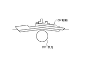
- FIG. 1A is a diagram showing a first step of a destruction method using bubble jet 204 by torpedo 40.
- the glaze provided in the torpedo 40 explodes at a close distance of the ship 100, air bubbles 201 are generated in the water.
- FIG. 1B is a diagram showing a second step of the destruction method using the bubble jet 204 by the torpedo 40.
- the air bubble 201 repeats expansion and contraction due to the interaction between the internal air pressure and the external water pressure. This phenomenon is called bubble pulse.
- FIG. 1C is a diagram showing a third step of the destruction method using the bubble jet 204 by the torpedo 40.
- a structure such as the bottom of the ship 100 is present in the vicinity of the air bubble 201 when the air bubble 201 is contracted, a pressure difference is generated between the structure side surface of the air bubble 201 and the opposite surface. .
- the air bubble 201 indents from the opposite surface toward the surface on the structure side, and a water flow 203 is generated.
- FIG. 1D is a diagram showing a fourth step of the destruction method using the bubble jet 204 by the torpedo 40.
- the water flow 203 becomes a bubble jet 204 and exerts a great force to destroy the structure of the ship 100 or the like.
- the power of the bubble jet 204 is often stronger than the shock wave 202 due to the explosion of the glaze.
- FIG. 2 is a diagram showing an example of a method for avoiding the attack by the torpedo 40.
- the torpedo 40 launched from the submarine 30 or the like detects the sound of the target when moving toward the target such as the ship 20 and moves toward the detected sound. Therefore, the targeted ship 20 deceives the submarine 30 and the torpedo 40 by transmitting a sound from a position away from itself.
- the ship 20 may transmit a sound from the towing decoy 21 or the self-propelled decoy 22.
- the torpedo 40 can move toward the decoy, and the targeted vessel 20 can avoid the threat of the torpedo 40.
- FIG. 3 is a view showing an example of the configuration of a high-power laser beam irradiation apparatus.
- the target 400 is irradiated with high-power laser light 303 output from the high-power laser irradiation apparatus 300.
- the high power laser irradiation apparatus 300 generates the high power laser beam 303 using the high power laser oscillator 301, and sets the irradiation direction of the high power laser beam 303 toward the target 400 using the irradiation optical system 302.
- the portion of the target 400 irradiated with the high power laser beam 303 is referred to as an irradiated portion 401 for convenience.
- a part or all of the target 400 is destroyed.
- the intensity of such high-power laser light 303 is attenuated according to the propagation distance. Nevertheless, such a high power laser irradiation apparatus 300 can destroy the target 400 from a distance of several kilometers apart when propagating in the air. However, when propagating in the water, it is attenuated more than propagating in the air. Therefore, in the embodiment described below, the laser light is collected in water and the water is boiled to generate bubbles. The bubble jet is generated by generating the bubble at a target position determined in relation to the underwater object such as the torpedo 40, and the bubble jet destroys the underwater object. Alternatively, the laser light is collected in water to generate plasma.
- the underwater object By generating the plasma at a target position determined in relation to the underwater object such as the torpedo 40, that is, based on the underwater object, the underwater object is destroyed by the shock wave accompanying the generation of the plasma.
- a bubble or plasma can be generated at the focusing position even after propagating through water and being attenuated, for example, within 20 meters from the irradiation side, or even further away therefrom.
- FIG. 4 is a block circuit diagram showing a configuration example of the underwater object destruction system 1 according to the first embodiment.
- the components of the underwater object destruction system 1 shown in FIG. 4 will be described.
- the underwater object destruction system 1 of FIG. 4 includes an external system 12, a controller 13, a pulse laser oscillator 14A, and an irradiation optical system 18A.
- the external system 12 is, for example, a ship control system provided in the ship 20, and preferably includes a sonar or the like for detecting the presence of an underwater object such as a torpedo 40 or the like.
- the control device 13 includes an input / output interface that transmits and receives signals, a memory that stores programs and data, and a central processing unit (CPU) that generates a signal by executing a program on the memory. It may be a computer.
- the irradiation optical system 18A desirably includes an optical device such as a lens or a reflecting mirror, and a driving device for adjusting the position of the lens, the angle of the reflecting mirror, and the like in order to adjust the irradiation direction and the focal length.
- the external system 12, the control device 13, the pulse laser oscillator 14A, and the irradiation optical system 18A may all be provided in the ship 20 etc. (not shown), and a part thereof is included in the ship 20 It may be provided in another place such as decoy or aircraft.
- the control device 13 is connected to the rear stage of the external system 12.
- a pulse laser oscillator 14A and an irradiation optical system 18A are connected to the rear stage of the control device.
- the electrical connection relationship may be realized by wired or wireless.
- Focusing on the optical connection relationship, the irradiation optical system 18A is disposed downstream of the pulse laser oscillator 14A. It is needless to say that the optical connection may be mediated by appropriately using optical components such as a mirror, a lens, a beam splitter and the like (not shown).
- FIG. 5 is a flowchart showing an example of the underwater object destruction method according to the first embodiment.
- the flowchart of FIG. 5 includes a total of six steps of the zeroth step S100 to the fifth step S105.
- the flowchart of FIG. 5 starts from the zeroth step S100. After the zeroth step S100, a first step S101 is performed.
- the underwater object destruction system 1 detects a target object 40. More specifically, the external system 12 detects the emission sound 31 emitted when the target object 40 is emitted, the navigation sound emitted when the target object 40 travels underwater, and any other sounds. The position of a torpedo as a target object 40 in the water, the moving direction, the moving speed, etc. are detected.
- FIG. 6A is a diagram showing an example of a state in which the underwater object destruction system 1 according to the first embodiment detects a target object 40 such as a torpedo.
- the second step S102 is performed after the first step S101.
- the underwater object destruction system 1 emits a pulse laser beam 51 so as to condense light at a target position determined based on the velocity, direction, and the like of the target object 40. More specifically, the external system 12 generates a detection signal 121 indicating the result of detecting the target object 40. The external system 12 transmits the generated detection signal 121 to the control device 13. The control device 13 receives the transmitted detection signal 121.
- the control device 13 generates an oscillation control signal 131A for controlling the oscillation of the pulse laser according to the received detection signal 121.
- the control device 13 transmits the generated oscillation control signal 131A toward the pulse laser oscillator 14A.
- the pulse laser oscillator 14A receives the transmitted oscillation control signal 131A.
- the pulse laser oscillator 14A oscillates a pulse laser in response to the received oscillation control signal 131A, and emits a pulse laser beam 51.
- the irradiation optical system 18A receives the emitted pulse laser light 51.
- the control device 13 controls an irradiation direction of the pulse laser beam 51 according to the received detection signal 121, and an irradiation direction control signal for controlling a position at which the irradiated pulse laser beam 51 is collected. Generate 134A.
- the control device 13 transmits the generated irradiation direction control signal 134A toward the irradiation optical system 18A.
- the irradiation optical system 18A receives the transmitted irradiation direction control signal 134A.
- the irradiation optical system 18A adjusts the direction in which the pulsed laser light 51 is irradiated according to the received irradiation direction control signal 134A, and adjusts the focal length at which the irradiated pulsed laser light 51 is collected.
- the irradiation optical system 18A irradiates the received pulsed laser light 51 so as to direct it in the adjusted direction and to condense it at the adjusted focal distance.
- a third step S103 is performed.
- a bubble 70 or plasma 60 is generated in the water by the irradiated laser light. More specifically, the irradiated pulsed laser light 51 is condensed at the adjusted position. The condensed pulse laser light 51 causes the surrounding water to boil and generate a bubble 70. Alternatively, surrounding water is turned into a plasma by the collected pulsed laser light 51, and a plasma 60 is generated.
- FIG. 6B is a view showing an example of a state in which the underwater object destruction system 1 according to the first embodiment irradiates laser light.
- the target object 40 is destroyed by the bubble jet 71 generated by the air bubble 70 or the shock wave 61 generated by the plasma 60.
- the bubble jet is generated when the bubble 70 is generated in the water by the pulse laser beam 51, the target object 40 is in the close distance of the bubble 70, or the target object 40 approaches the bubble 70. 71 is generated, and the generated bubble jet 71 destroys the target object 40.
- a shock wave is generated by the plasma 60 when the plasma 60 is generated in water by the pulsed laser light 51 and the target object 40 is at a close distance of the plasma 60 or when the target object 40 approaches the plasma 60. 61 destroys the target object 40.
- FIG. 6C is a view showing an example of the underwater object destruction system 1 according to the first embodiment in a state where the target object 40 approaches at a close distance from the plasma 60 or the bubble 70 generated by the laser light.
- FIG. 6D is a view showing an example of a state in which the underwater object destruction system 1 according to the first embodiment destroys the target object 40 with the bubble jet 71 by the air bubbles 70.
- FIG. 6E is a view showing an example of a state in which the underwater object destruction system 1 according to the first embodiment destroys the target object 40 with the shock wave 61 by the plasma 60.
- the underwater object destruction system 1 may include, for example, a plurality of pulsed laser oscillators 14A.
- the underwater object destruction system 1 can emit a plurality of pulse laser beams 51 at one time and condense them at different positions to generate a plurality of bubbles 70 or plasma 60 at one time.
- the pulse laser beam 51 may be intermittently emitted at short intervals intermittently by a single pulse laser oscillator 14A, and the plurality of bubbles 70 or the plasma 60 may be generated continuously by condensing them at different positions.
- FIG. 7A is a view showing an example of a state in which the underwater object destruction system 1 according to the first embodiment irradiates a plurality of laser beams.
- the underwater object destruction system 1 irradiates a plurality of pulsed laser beams 51 at one time or continuously to form a plurality of bubbles 70 or plasma 60 in a wall or a net. It can be generated side by side.
- FIG. 7B is a view showing an example of the underwater object destruction system 1 according to the first embodiment emitting a plurality of laser beams to generate a plurality of bubbles 70 or a plurality of plasmas 60.
- FIG. 8A is a view showing a configuration example in the case where the submarine 23 emits a laser beam from water in the underwater object destruction system 1 according to the first embodiment.
- the underwater object destruction system 1 according to the present embodiment can be mounted on a ship 20, for example.
- the pulsed laser light 51 can be irradiated from the water or from above the water.
- FIG. 8B is a view showing a configuration example in the case where the ship 20 irradiates laser light from the water in the underwater object destruction system 1 according to the first embodiment.
- FIG. 8C is a view showing a configuration example of the case where the ship 20 irradiates the laser light from the air in the underwater object destruction system 1 according to the first embodiment.
- FIG. 8D is a diagram showing a configuration example of the case where the aircraft 24 emits laser light from the air in the underwater object destruction system according to the first embodiment.
- the underwater object destruction system 1 and the underwater object destruction method of the present embodiment it is possible to destroy and avoid the threat caused by the underwater object such as the torpedo 40.
- the pulse laser since the pulse laser has a large instantaneous output, the time lag from the irradiation to the generation of the bubble 70 or the plasma 60 can be suppressed to the order of nanoseconds.
- the pulse laser since the pulse laser has a small time-averaged output, the power required to destroy the threat underwater object can be reduced.
- FIG. 9 is a block circuit diagram showing one configuration example of the underwater object destruction system 1 according to the second embodiment.
- the underwater object destruction system 1 according to the present embodiment shown in FIG. 9 has the following differences compared to the underwater object destruction system 1 according to the first embodiment shown in FIG. That is, in the present embodiment, the continuous wave laser light 52 is used instead of the pulse laser light 51 used in the first embodiment.
- the pulse laser oscillator 14A and the irradiation optical system 18A of the first embodiment are replaced with the continuous wave laser oscillator 14B and the irradiation optical system 18B shown in FIG. 9, respectively.
- the other configuration of the underwater object destruction system 1 according to the present embodiment is the same as that of the first embodiment, and thus further detailed description will be omitted.
- the continuous wave laser beam 52 used in the present embodiment can generate a bubble 70 by condensing in water as in the pulsed laser beam 51 of the first embodiment. Furthermore, the continuous wave laser light 52 can be emitted without interruption, and hence the bubble 70 can be generated continuously. Here, the continuous wave laser beam 52 can generate a single long bubble 70 by moving the condensing position while generating continuously.
- FIG. 10 is a flowchart showing an example of the underwater object destruction method according to the second embodiment.
- the flowchart of FIG. 10 includes a total of seven steps of the zeroth step S200 to the sixth step S206.
- the flowchart of FIG. 10 starts from the zeroth step S200. After the zeroth step S200, a first step S201 is performed.
- the underwater object destruction system 1 detects a target object 40.
- the first step S201 according to the present embodiment is similar to the first step S101 according to the first embodiment, and thus further detailed description will be omitted.
- a second step S202 is performed.
- the underwater object destruction system 1 emits a laser beam so as to condense light at a target position determined in relation to the target object 40. More specifically, the external system 12 generates a detection signal 121 indicating the result of detecting the target object 40. The external system 12 transmits the generated detection signal 121 to the control device 13. The control device 13 receives the transmitted detection signal 121.
- the control device 13 generates an oscillation control signal 131 B for controlling the oscillation of the continuous wave laser light 52 in accordance with the received detection signal 121.
- the controller 13 transmits the generated oscillation control signal 131B toward the continuous wave laser oscillator 14B.
- the continuous wave laser oscillator 14B receives the transmitted oscillation control signal 131B.
- the continuous wave laser oscillator 14B oscillates the continuous wave laser beam 52 in response to the received oscillation control signal 131B.
- the continuous wave laser oscillator 14B emits the oscillated continuous wave laser light 52 toward the irradiation optical system 18B.
- the irradiation optical system 18B receives the emitted continuous wave laser light 52.
- the control device 13 controls the irradiation direction of the continuous wave laser light 52 according to the received detection signal 121, and controls the position at which the irradiated continuous wave laser light 52 is collected.
- Control signal 134B is generated.
- the control device 13 transmits the generated irradiation direction control signal 134B toward the irradiation optical system 18B.
- the irradiation optical system 18B receives the transmitted irradiation direction control signal 134B.
- the irradiation optical system 18B adjusts the direction in which the continuous wave laser light 52 is irradiated according to the received irradiation direction control signal 134B, and adjusts the focal length at which the irradiated continuous wave laser light 52 is collected.
- the irradiation optical system 18B irradiates the received continuous wave laser light 52 so as to direct it in the adjusted direction and to condense it at the adjusted focal distance.
- the bubble 70 is generated in the water by the irradiated continuous wave laser light 52. More specifically, the irradiated continuous wave laser light 52 is condensed at the adjusted position. The condensed continuous wave laser light 52 causes the surrounding water to boil and generate air bubbles 70. Here, the continuous wave laser light 52 is continuously irradiated and the bubble 70 is also continuously generated.
- FIG. 11A is a view showing an example of a state in which the underwater object destruction system 1 according to the second embodiment irradiates the continuous wave laser light 52.
- FIG. 11B is a view showing a state in which the target object 40 approaches while the underwater object destruction system 1 according to the second embodiment continues to emit the continuous wave laser light 52.
- a fifth step S205 is performed.
- the target object 40 is destroyed by the bubble jet 71 generated by the air bubble 70. More specifically, a bubble 70 is generated in water by the continuous wave laser beam 52, and as a result of the target object 40 approaching the bubble 70, a bubble jet 71 is generated and the generated bubble jet 71 destroys the target object 40.
- FIG. 11C is a view showing a state where the target object 40 is destroyed by the air bubble 70 generated by the continuous wave laser light 52 continuously irradiated by the underwater object destruction system 1 according to the second embodiment.
- a sixth step S206 is performed, and the flowchart of FIG. 10 ends.
- the continuous wave laser beam 52 can generate a plurality of bubbles 70 by intermittently irradiating it while changing the condensing position. Since this configuration example is the same as that of the first embodiment shown in FIG. 7A, further detailed description will be omitted.
- the continuous wave laser beam 52 can wait for the target object 40 with high accuracy by irradiating the bubbles 70 so as to be lined up at a constant interval. Since this configuration example is the same as that of the first embodiment shown in FIG. 7B, further detailed description will be omitted.
- the continuous wave laser oscillator 14B and the irradiation optical system 18B can be mounted on the submarine 23, the ship 20, the aircraft 24, etc., as in the case of the first embodiment shown in FIGS. 8A to 8D. In these cases, it is possible to irradiate the continuous wave laser light 52 from water or air.
- the continuous wave laser light 52 has a lower instantaneous output than the pulsed laser light 51. Therefore, it takes a time lag of several tens of milliseconds to several hundreds of milliseconds to generate air bubbles 70 after irradiation.
- the target object 40 such as a torpedo can be detected with high accuracy, but the movement speed can not be detected with high accuracy. 40 destruction can be realized with higher probability.
- the advantages of the first embodiment and the second embodiment can be obtained by using the pulse laser beam 51 used in the first embodiment and the continuous wave laser beam 52 used in the second embodiment in combination. compatible.
- the pulsed laser light 51 and the continuous wave laser light 52 may be irradiated one by one by the switching operation, or both may be irradiated simultaneously.
- FIG. 12A is a block circuit diagram showing a first configuration example of the underwater object destruction system 1 according to the third embodiment.
- the underwater object destruction system 1 of FIG. 12A includes a control device 13, a pulse laser oscillator 14A, a continuous wave laser oscillator 14B, an irradiation optical system 18A for the pulse laser, and an irradiation optical system 18B for the continuous wave laser. .
- the first configuration example of the third embodiment shown in FIG. 12A has the following differences compared to the case of the first embodiment shown in FIG. That is, a continuous wave laser oscillator 14B and an irradiation optical system 18B for the continuous wave laser are added. Moreover, the first configuration example of the third embodiment shown in FIG. 12A has the following differences compared to the case of the second embodiment shown in FIG. That is, a pulse laser oscillator 14A and an irradiation optical system 18A for the pulse laser are added.
- the configurations and connection relationships of the control device 13, the pulse laser oscillator 14A, and the irradiation optical system 18A for the pulse laser are the same as those in the first embodiment, and thus further detailed description will be omitted.
- the configuration and connection relationship of the control device 13, the continuous wave laser oscillator 14B, and the irradiation optical system 18B for the continuous wave laser are the same as those in the second embodiment, and thus further detailed description will be omitted.
- the controller 13 controls the oscillation control signal 131A for controlling the oscillation of the pulse laser beam 51 and the oscillation for controlling the oscillation of the continuous wave laser beam 52 in accordance with the detection signal 121 received from the external system 12 (not shown). It is desirable to generate and output the control signal 131B at appropriate timing.
- the other operations of the underwater object destruction system 1 according to the first configuration example of the present embodiment are the same as those in the first embodiment or the second embodiment, and thus further detailed description will be omitted.
- FIG. 12B is a block circuit diagram showing a second configuration example of the underwater object destruction system 1 according to the third embodiment.
- the underwater object destruction system 1 of FIG. 12B has the following differences compared to the case of the first embodiment shown in FIG. That is, the continuous wave laser oscillator 14B and the switching device 16 are added.
- the switching device 16 may be provided with two light receiving ports, one emitting port, a reflecting mirror different from the reflecting mirror 15, and a driving device for adjusting the position or angle of the reflecting mirror. desirable.
- control device 13 and the pulse laser oscillator 14A are the same as in the first embodiment, and thus further detailed description will be omitted.
- configurations and connection relationships of the control device 13 and the continuous wave laser oscillator 14B are the same as in the second embodiment, and thus further detailed description will be omitted.
- the switching device 16 and the irradiation optical system 18C are each connected to the control device 13. Further, focusing on the optical connection relationship, the switching device 16 is disposed downstream of the pulse laser oscillator 14A, and the irradiation optical system 18C is disposed downstream of the switching device 16. Furthermore, the switching device 16 is disposed downstream of the continuous wave laser oscillator 14B via the reflecting mirror 15. The reflecting mirror 15 may be disposed between the pulse laser oscillator 14A and the switching device 16.
- the series of operations from the generation of the oscillation control signal 131A by the control device 13 to the oscillation of the pulse laser beam 51 by the pulse laser oscillator 14A are the same as those in the first embodiment.
- the series of operations from the generation of the oscillation control signal 131B by the control device 13 to the oscillation of the continuous wave laser light 52 by the continuous wave laser oscillator 14B are the same as those in the second embodiment.
- the switching device 16 receives the pulse laser beam 51 at the first light receiving port, and receives the continuous wave laser beam 52 via the reflecting mirror 15 at the second light receiving port.
- the reflecting mirror 15 guides the continuous wave laser light 52 from the emission port of the continuous wave laser oscillator 14 B to the second light receiving port of the switching device 16.
- the control device 13 generates a switching control signal 132 for controlling switching of the pulse laser light 51 and the continuous wave laser light 52.
- the control device 13 transmits the generated switching control signal 132 to the switching device 16.
- the switching device 16 receives the transmitted switching control signal 132.
- the switching device 16 adjusts the position, angle, and the like of the reflecting mirror by the driving device in accordance with the received switching control signal 132. By doing this, the switching device 16 can switch between the first state and the second state under the control of the control device 13. That is, the switching device 16 in the first state selectively emits pulse laser light 51 received from the first light receiving port from the emitting port. Further, the switching device 16 in the second state selectively emits the continuous wave laser light 52 received from the second light receiving port from the emitted light.
- the irradiation optical system 18C receives the pulse laser light 51 or the continuous wave laser light 52 selectively emitted.
- the control device 13 generates an irradiation direction control signal 134C for controlling the direction in which the irradiation optical system 18C irradiates the laser light and controlling the position at which the laser light condenses.
- the control device 13 transmits the generated irradiation direction control signal 134C toward the irradiation optical system 18C.
- the irradiation optical system 18C receives the transmitted irradiation direction control signal 134C.
- the irradiation optical system 18C adjusts the irradiation direction and the focal length in accordance with the received irradiation direction control signal 134C.
- the irradiation optical system 18C irradiates the received pulsed laser light 51 or the continuous wave laser light 52 so as to focus in the adjusted irradiation direction and to the adjusted focal length.
- the control device 13 preferably generates and outputs the oscillation control signal 131A, the oscillation control signal 131B, and the switching control signal 132 at appropriate timings according to the detection signal 121 received from the external system 12 (not shown). .
- the other operations of the underwater object destruction system 1 according to the second configuration example of the present embodiment are the same as those of the first embodiment or the second embodiment, and thus further detailed description will be omitted.
- FIG. 12C is a block circuit diagram showing a third configuration example of the underwater object destruction system according to the third embodiment.
- the underwater object destruction system 1 of FIG. 12C includes a control device 13, a pulse / continuous wave switchable laser oscillator 14C, and an irradiation optical system 18C.
- the pulse / continuous wave switchable laser oscillator 14 C has a first state and a second state which are switched under the control of the controller 13. That is, the pulse / continuous wave switchable laser oscillator 14C oscillates the pulse laser beam 51 in the first state, and oscillates the continuous wave laser beam 52 in the second state.
- a pulsing device such as a so-called "Q switch” and a method of using the same are conceivable. That is, the pulsed / continuous wave switchable laser oscillator 14C in the first state is optically connected to the pulsed device, and oscillates the pulsed laser beam 51.
- the pulsed / continuous wave switchable laser oscillator 14 C in the second state has the pulsed device optically disconnected and oscillates the continuous wave laser light 52.
- the connection relation of each component shown in FIG. 12C will be described. Focusing on the electrical connection relationship, the pulse / continuous wave switchable laser oscillator 14C and the irradiation optical system 18C are each connected to the control device 13. Further, focusing on the optical connection relationship, the irradiation optical system 18C is disposed at the rear stage of the pulse / continuous wave switchable laser oscillator 14C.
- the control device 13 generates an oscillation control signal 131C for controlling oscillation of the pulse laser beam 51 or the continuous wave laser beam 52 and switching thereof.
- the control device 13 transmits the generated oscillation control signal 131C toward the pulse / continuous wave switchable laser oscillator 14C.
- the pulse / continuous wave switchable laser oscillator 14C receives the transmitted oscillation control signal 131C.
- the pulse / continuous wave switchable laser oscillator 14C selectively oscillates the pulse laser beam 51 or the continuous wave laser beam 52 in accordance with the received oscillation control signal 131C.
- the pulse / continuous wave switchable laser oscillator 14C emits the oscillated pulse laser light 51 or the continuous wave laser light 52 toward the irradiation optical system 18C.
- the operation from the generation of the irradiation direction control signal 134C by the control device 13 to the irradiation of the pulsed laser light 51 or the continuous wave laser light 52 by the irradiation optical system 18C is the second embodiment of the third embodiment shown in FIG. 12B. As it is similar to the case of the configuration example, further detailed description is omitted.
- the pulsed laser beam 51 and the continuous wave laser beam 52 are simultaneously irradiated, as a fourth configuration example of the underwater object destruction system 1 according to the present embodiment, the pulsed laser beam 51 and the continuous wave laser beam 52 respectively oscillate from different oscillators. And, it may be irradiated respectively from different irradiation optical systems.
- the block circuit diagram showing the fourth configuration example of the underwater object destruction system 1 according to the third embodiment is the same as FIG. 12A showing the first configuration example of the third embodiment, and thus is omitted here.
- the underwater object destruction system 1 according to this configuration example can simultaneously emit the pulse laser beam 51 and the continuous wave laser beam 52. Therefore, in the present configuration example, the control device 13 may simultaneously transmit the oscillation control signal 131A and the oscillation control signal 131B to the pulse laser oscillator 14A and the continuous wave laser oscillator 14B.
- the other configuration and operation of the underwater object destruction system 1 according to the present configuration example are the same as in the case of the first embodiment or the second embodiment, and thus further detailed description will be omitted.
- FIG. 12D is a block circuit diagram showing a fifth configuration example of the underwater object destruction system 1 according to the third embodiment.
- the underwater object destruction system 1 of FIG. 12D has the following differences as compared with the second configuration example of the present embodiment shown in FIG. 12B. That is, the switching device 16 is replaced by the coaxializing device 17.
- the coaxialization device 17 be provided with two light receiving ports and one light emitting port. The coaxialization device 17 coaxializes the two laser beams respectively received by the two light receiving ports and emits the laser light from the emission port.
- control device 13 and the pulse laser oscillator 14A are the same as in the first embodiment, and thus further detailed description will be omitted.
- configurations and connection relationships of the control device 13 and the continuous wave laser oscillator 14B are the same as in the second embodiment, and thus further detailed description will be omitted.
- connection relation of each component according to the coaxial device 17 will be described. Focusing on the electrical connection relation, the coaxializing device 17 is connected to the control device 13. Further, focusing on the optical connection relationship, the first light receiving port of the coaxializing device 17 is disposed downstream of the pulse laser oscillator 14A. The second light receiving port of the coaxializing device 17 is disposed downstream of the continuous wave laser oscillator 14B via the reflecting mirror 15. An irradiation optical system 18C is disposed downstream of the coaxializing device 17.
- the series of operations from the generation of the oscillation control signal 131A by the control device 13 to the oscillation of the pulse laser beam 51 by the pulse laser oscillator 14A are the same as those in the first embodiment.
- the pulse laser oscillator 14A emits the oscillated pulse laser beam 51 toward the first light receiving port of the coaxializing device 17.
- the coaxializing device 17 receives the emitted pulse laser light 51 at the first light receiving port.
- the series of operations from the generation of the oscillation control signal 131 B by the control device 13 to the oscillation of the continuous wave laser light 52 by the continuous wave laser oscillator 14 B are the same as in the second embodiment.
- the continuous wave laser oscillator 14B emits the oscillated continuous wave laser beam 52 toward the second light receiving port of the coaxializing device 17.
- the control device 13 generates a coaxialization control signal 133 for controlling the coaxialization of the pulse laser light 51 and the continuous wave laser light 52.
- the control device 13 transmits the generated coaxialization control signal 133 toward the coaxialization device 17.
- the coaxialization device 17 receives the transmitted coaxialization control signal 133.
- the coaxializing device 17 is responsive to the received coaxialization control signal 133, the optical axis direction of the first light receiving port that receives the pulse laser light 51, and the optical axis direction of the second light receiving port that receives the continuous wave laser light 52. And the optical axis direction of the exit which emits the coaxialized pulse laser light 51 and the continuous wave laser light 52 respectively.
- the coaxializing device 17 receives the emitted pulse laser light 51 at a first light receiving port whose optical axis direction is adjusted.
- the coaxializing device 17 receives the emitted continuous wave laser beam 52 at a second light receiving port whose optical axis direction is adjusted.
- the coaxializing device 17 coaxializes the received pulse laser light 51 and continuous wave laser light 52 and emits the light from the exit whose optical axis direction is adjusted.
- the control device 13 generates and outputs an oscillation control signal 131A, an oscillation control signal 131B, and a coaxialization control signal 133 in accordance with a detection signal 121 received from an external system 12 (not shown).
- the other operations of the underwater object destruction system 1 according to the fifth configuration example of the third embodiment are the same as in the first embodiment or the second embodiment, and thus further detailed description will be omitted.
- the underwater object destruction system 1 and the underwater object destruction method according to the third embodiment implement the first embodiment by switching or simultaneously irradiating the pulse laser beam 51 and the continuous wave laser beam 52. It is possible to make the advantages of the embodiment and the second embodiment compatible.
- feedback control is added to the first to third embodiments. That is, a sound indicating that the air bubble 70 or the plasma 60 is generated by the irradiation of the laser light, or a silent state indicating the end of the non-emission is observed by an observation device such as a sonar, and the result is fed back to the irradiation. Adjust the optical system.
- FIG. 13 is a block circuit diagram showing a configuration example of the underwater object destruction system 1 according to the fourth embodiment.
- the underwater object destruction system 1 shown in FIG. 13 adds a sonar 11 to the third configuration example of the third embodiment shown in FIG. 12C.
- the sonar 11 is electrically connected to the control device 13.
- the sonar 11 may be part of an external system 12 (not shown).
- FIG. 14 is a flowchart showing an example of the underwater object destruction method according to the fourth embodiment.
- the flowchart of FIG. 14 includes a total of eight steps of the zeroth step S300 to the seventh step S307.
- the flowchart of FIG. 14 starts from the zeroth step S300. After the zeroth step S300, a first step S301 is performed.
- the underwater object destruction system 1 detects a target object 40.
- the first step S301 according to the present embodiment is similar to the first step S101 according to the first embodiment, and thus further detailed description will be omitted.
- a second step S302 is performed.
- the underwater object destruction system 1 emits pulsed laser light 51 or continuous wave laser light 52 so as to condense light at a target position determined in relation to the target object 40. Since this operation is the same as that of the third configuration example of the third embodiment, further detailed description will be omitted.
- FIG. 15A is a view showing an example of a state in which the underwater object destruction system 1 according to the fourth embodiment irradiates laser light.
- the underwater object destruction system 1 observes the result. That is, whether or not the bubble 70 or the plasma 60 is generated by the irradiation of the laser light, and if it is generated, whether or not the target object 40 is broken is determined by observing the surrounding sound with the sonar 11.
- the sonar 11 electrically converts the observed sound 111 to generate an observation signal 112, and transmits the generated observation signal 112 to the control device 13.
- the control device 13 receives the transmitted observation signal 112 and makes the above determination.
- FIG. 15B is a diagram showing an example of a state in which it is detected that the laser light emitted by the underwater object destruction system 1 according to the fourth embodiment is focused at a near distance than expected.
- the shock wave generated as a result is observed by the sonar 11
- the light is estimated to be collected 90 meters from the irradiation optical system 18C.
- FIG. 15C is a diagram showing an example of a state in which it is detected that the shock wave is not generated because the laser light emitted by the underwater object destruction system 1 according to the fourth embodiment is not collected.
- the irradiation condition is adjusted so as to be condensed 100 meters away from the irradiation optical system 18C and then the pulsed laser light 51 is irradiated, the shock wave to be generated as a result can be observed by the sonar 11 within a predetermined time. If not, it is possible. The cause of such failure is that the attenuation during the propagation of the laser light is greater than expected, and sufficient energy may not reach the focusing point, or the laser light is not sufficiently focused due to the influence of the tidal current Potential. If the bubble 70 or the plasma 60 is not generated (NO), a sixth step S306 is performed after the fourth step S304.
- the underwater object destruction system 1 determines whether or not the target object 40 has been destroyed.
- the target object 40 is destroyed, a sound indicating that fact is generated, and the sonar 11 can detect this sound.
- the seventh step S307 is executed after the fifth step S305, and the flowchart of FIG. 14 ends.
- the target object 40 can not detect the broken sound while the air bubble 70 or the plasma 60 is generated, as shown in FIG. 15B, the laser light is condensed at a position different from the assumed one. There may be a cause such as In this case (NO), the sixth step S306 is executed after the fifth step S305.
- the underwater object destruction system 1 feeds back the observation result to adjust the irradiation condition of the laser light.
- the irradiation conditions to be adjusted include, for example, selection of pulse laser light 51 or continuous wave laser light 52, output intensity of laser light, irradiation direction of laser light, condensing position of laser light, etc. good.
- a first step S301 is performed.
- FIG. 15D is a diagram showing an example of a state in which the underwater object destruction system 1 according to the fourth embodiment irradiates laser light again by feedback control.
- the effects of the movement of the ship 20 equipped with the underwater object destruction system 1 and the tidal current around the ship 20 or the target object 40 are corrected to collect the laser light. It becomes possible to perform light more precisely.
- FIG. 16 is a view showing a configuration example of the underwater object destruction system 1 according to the fifth embodiment. In the configuration example shown in FIG. 16, the towing decoy 21 and the self-propelled decoy 22 are separated from the ship 20.
- the towed decoy 21 is equipped with an irradiation optical system, and can irradiate the pulse laser light 51, and can destroy the target object 40 by a shock wave 61 generated as a result.
- the towed decoy 21 may destroy the target object 40 with pulsed laser light, or may irradiate the continuous wave laser light 52.
- the laser oscillator may be mounted on the towing decoy 21, the towing decoy 21 and the ship 20 are physically connected to each other by a towing cable or the like. It is also possible to mount it. That is, in the latter case, the laser oscillator and the irradiation optical system are optically connected using an optical system such as an optical fiber, and the laser light emitted from the laser oscillator of the ship 20 is a towed decoy 21. It is possible to guide and emit light to the irradiation optical system.
- the self-propelled decoy 22 can also emit the pulse laser beam 51 and destroy the target object 40 by the shock wave 61 generated as a result thereof, similarly to the towed decoy 21.
- the self-propelled decoy 22 since the self-propelled decoy 22 has no physical connection with the ship 20, it is desirable that the self-propelled decoy 22 be equipped with a laser oscillator.
- the self-propelled decoy 22 may also destroy the target object 40 with pulsed laser light, or may irradiate the continuous wave laser light 52.
- the present embodiment it is possible to generate the bubble jet 71 and the shock wave 61 at a distance of the ship 20 by irradiating the laser light from the towed decoy 21 or the self-propelled decoy 22 separated from the ship 20. It becomes. Therefore, the influence of the destruction of the target object 40 such as a torpedo on the ship 20 to be protected can be reduced.
Landscapes
- Engineering & Computer Science (AREA)
- Physics & Mathematics (AREA)
- Optics & Photonics (AREA)
- General Engineering & Computer Science (AREA)
- Aviation & Aerospace Engineering (AREA)
- Electromagnetism (AREA)
- Radar, Positioning & Navigation (AREA)
- Remote Sensing (AREA)
- Plasma & Fusion (AREA)
- General Physics & Mathematics (AREA)
- Lasers (AREA)
- Aiming, Guidance, Guns With A Light Source, Armor, Camouflage, And Targets (AREA)
- Laser Beam Processing (AREA)
- Optical Radar Systems And Details Thereof (AREA)
Priority Applications (2)
| Application Number | Priority Date | Filing Date | Title |
|---|---|---|---|
| US16/325,083 US11181347B2 (en) | 2016-11-08 | 2017-02-14 | Underwater object destruction system and underwater object destruction method |
| EP17869406.3A EP3489616B1 (en) | 2016-11-08 | 2017-02-14 | Underwater object destruction system and underwater object destruction method |
Applications Claiming Priority (2)
| Application Number | Priority Date | Filing Date | Title |
|---|---|---|---|
| JP2016-218229 | 2016-11-08 | ||
| JP2016218229A JP6774305B2 (ja) | 2016-11-08 | 2016-11-08 | 水中物体破壊システムおよび水中物体破壊方法 |
Publications (1)
| Publication Number | Publication Date |
|---|---|
| WO2018087939A1 true WO2018087939A1 (ja) | 2018-05-17 |
Family
ID=62109650
Family Applications (1)
| Application Number | Title | Priority Date | Filing Date |
|---|---|---|---|
| PCT/JP2017/005219 Ceased WO2018087939A1 (ja) | 2016-11-08 | 2017-02-14 | 水中物体破壊システムおよび水中物体破壊方法 |
Country Status (4)
| Country | Link |
|---|---|
| US (1) | US11181347B2 (https=) |
| EP (1) | EP3489616B1 (https=) |
| JP (1) | JP6774305B2 (https=) |
| WO (1) | WO2018087939A1 (https=) |
Families Citing this family (3)
| Publication number | Priority date | Publication date | Assignee | Title |
|---|---|---|---|---|
| EP3657208A4 (en) * | 2018-02-14 | 2020-08-12 | Mitsubishi Heavy Industries, Ltd. | UNDERWATER ACOUSTIC LURRING SYSTEM AND UNDERWATER ACOUSTIC LURRING PROCESS |
| JP7336921B2 (ja) * | 2019-09-03 | 2023-09-01 | 三菱電機株式会社 | レーザ照射装置およびレーザ照射システム |
| US12399263B2 (en) * | 2021-11-15 | 2025-08-26 | The United States Of America, As Represented By The Secretary Of The Navy | Target jamming |
Citations (1)
| Publication number | Priority date | Publication date | Assignee | Title |
|---|---|---|---|---|
| US20030233931A1 (en) * | 2002-06-14 | 2003-12-25 | Nemtsev Igor Z. | Synchronized photo-pulse detonation (SPD) |
Family Cites Families (5)
| Publication number | Priority date | Publication date | Assignee | Title |
|---|---|---|---|---|
| GB8828680D0 (en) * | 1988-12-08 | 2000-10-04 | British Aerospace | Underwater detection system |
| DE10151597C1 (de) | 2001-10-18 | 2003-05-15 | Howaldtswerke Deutsche Werft | System und Verfahren zur Erkennung und Abwehr von Laserbedrohungen und Unterwasserobjekten für Unterwasserfahrzeuge |
| US20160097616A1 (en) * | 2011-11-25 | 2016-04-07 | Dr. Adam Mark Weigold | Laser Guided and Laser Powered Energy Discharge Device |
| US9088123B2 (en) * | 2011-12-13 | 2015-07-21 | The United States Of America, As Represented By The Secretary Of The Navy | Two-laser generation of extended underwater plasma |
| JP6376408B2 (ja) * | 2015-06-30 | 2018-08-22 | 三菱重工業株式会社 | 電磁パルス防護方法及び電磁パルス防護システム |
-
2016
- 2016-11-08 JP JP2016218229A patent/JP6774305B2/ja active Active
-
2017
- 2017-02-14 EP EP17869406.3A patent/EP3489616B1/en active Active
- 2017-02-14 US US16/325,083 patent/US11181347B2/en active Active
- 2017-02-14 WO PCT/JP2017/005219 patent/WO2018087939A1/ja not_active Ceased
Patent Citations (1)
| Publication number | Priority date | Publication date | Assignee | Title |
|---|---|---|---|---|
| US20030233931A1 (en) * | 2002-06-14 | 2003-12-25 | Nemtsev Igor Z. | Synchronized photo-pulse detonation (SPD) |
Also Published As
| Publication number | Publication date |
|---|---|
| JP6774305B2 (ja) | 2020-10-21 |
| EP3489616B1 (en) | 2021-06-16 |
| US11181347B2 (en) | 2021-11-23 |
| JP2018076992A (ja) | 2018-05-17 |
| US20210285745A1 (en) | 2021-09-16 |
| EP3489616A1 (en) | 2019-05-29 |
| EP3489616A4 (en) | 2019-08-07 |
Similar Documents
| Publication | Publication Date | Title |
|---|---|---|
| JP6376408B2 (ja) | 電磁パルス防護方法及び電磁パルス防護システム | |
| JP6376407B2 (ja) | 電磁パルス照射方法及び電磁パルス照射システム | |
| JP6883700B2 (ja) | 水中音響欺瞞システムおよび水中音響欺瞞方法 | |
| WO2018087939A1 (ja) | 水中物体破壊システムおよび水中物体破壊方法 | |
| KR102212361B1 (ko) | 레이저음향기기를 이용한 수중표적 공격용 양상태 탐지시스템 및 탐지방법 | |
| JP7336921B2 (ja) | レーザ照射装置およびレーザ照射システム | |
| EP4115137A1 (en) | Plasma burst application system and method | |
| PT1304290E (pt) | Sistema e processo para a deteccao de e a defesa contra ameacas por laser e objectos subaquaticos, destinados a veiculos subaquaticos | |
| WO2020152903A1 (ja) | レーザ照射装置及びレーザ照射プログラムを格納する記憶媒体 | |
| JP2018076992A5 (https=) | ||
| AU2018277594B2 (en) | Weapon system | |
| US10883802B2 (en) | Weapon system | |
| JP3624853B2 (ja) | レーザセミアクティブ誘導方法及びレーザセミアクティブ誘導方式 | |
| JP6788480B2 (ja) | レーザ光通信システムおよびレーザ光通信方法 | |
| GB2565403A (en) | Weapon system | |
| JP6654028B2 (ja) | レーザ防御システム、および、レーザ防御方法 | |
| JP2012208370A (ja) | 指向エネルギーシステム | |
| KR102685469B1 (ko) | 자기장 신호 기반의 수중 운동체 기만 제어 방법 및 그를 위한 장치 | |
| RU2812655C1 (ru) | Способ уничтожения цели с помощью лазера | |
| RU2013138591A (ru) | Многофункциональный оптический коррелятор для обработки потока информации | |
| JP2015054344A (ja) | レーザ照射システム | |
| JPS62124483A (ja) | セミアクティブ誘導用レ−ザレ−ダ装置 | |
| GB2346751A (en) | Torpedo guidance system |
Legal Events
| Date | Code | Title | Description |
|---|---|---|---|
| 121 | Ep: the epo has been informed by wipo that ep was designated in this application |
Ref document number: 17869406 Country of ref document: EP Kind code of ref document: A1 |
|
| ENP | Entry into the national phase |
Ref document number: 2017869406 Country of ref document: EP Effective date: 20190222 |
|
| NENP | Non-entry into the national phase |
Ref country code: DE |