WO2018087928A1 - リチウムイオン二次電池用負極材、リチウムイオン二次電池用負極及びリチウムイオン二次電池 - Google Patents
リチウムイオン二次電池用負極材、リチウムイオン二次電池用負極及びリチウムイオン二次電池 Download PDFInfo
- Publication number
- WO2018087928A1 WO2018087928A1 PCT/JP2016/083714 JP2016083714W WO2018087928A1 WO 2018087928 A1 WO2018087928 A1 WO 2018087928A1 JP 2016083714 W JP2016083714 W JP 2016083714W WO 2018087928 A1 WO2018087928 A1 WO 2018087928A1
- Authority
- WO
- WIPO (PCT)
- Prior art keywords
- negative electrode
- lithium ion
- ion secondary
- secondary battery
- carbon
- Prior art date
- Legal status (The legal status is an assumption and is not a legal conclusion. Google has not performed a legal analysis and makes no representation as to the accuracy of the status listed.)
- Ceased
Links
Classifications
-
- H—ELECTRICITY
- H01—ELECTRIC ELEMENTS
- H01M—PROCESSES OR MEANS, e.g. BATTERIES, FOR THE DIRECT CONVERSION OF CHEMICAL ENERGY INTO ELECTRICAL ENERGY
- H01M4/00—Electrodes
- H01M4/02—Electrodes composed of, or comprising, active material
- H01M4/36—Selection of substances as active materials, active masses, active liquids
- H01M4/58—Selection of substances as active materials, active masses, active liquids of inorganic compounds other than oxides or hydroxides, e.g. sulfides, selenides, tellurides, halogenides or LiCoFy; of polyanionic structures, e.g. phosphates, silicates or borates
- H01M4/583—Carbonaceous material, e.g. graphite-intercalation compounds or CFx
- H01M4/587—Carbonaceous material, e.g. graphite-intercalation compounds or CFx for inserting or intercalating light metals
-
- H—ELECTRICITY
- H01—ELECTRIC ELEMENTS
- H01M—PROCESSES OR MEANS, e.g. BATTERIES, FOR THE DIRECT CONVERSION OF CHEMICAL ENERGY INTO ELECTRICAL ENERGY
- H01M10/00—Secondary cells; Manufacture thereof
- H01M10/05—Accumulators with non-aqueous electrolyte
- H01M10/052—Li-accumulators
- H01M10/0525—Rocking-chair batteries, i.e. batteries with lithium insertion or intercalation in both electrodes; Lithium-ion batteries
-
- H—ELECTRICITY
- H01—ELECTRIC ELEMENTS
- H01M—PROCESSES OR MEANS, e.g. BATTERIES, FOR THE DIRECT CONVERSION OF CHEMICAL ENERGY INTO ELECTRICAL ENERGY
- H01M4/00—Electrodes
- H01M4/02—Electrodes composed of, or comprising, active material
- H01M4/13—Electrodes for accumulators with non-aqueous electrolyte, e.g. for lithium-accumulators; Processes of manufacture thereof
- H01M4/133—Electrodes based on carbonaceous material, e.g. graphite-intercalation compounds or CFx
-
- H—ELECTRICITY
- H01—ELECTRIC ELEMENTS
- H01M—PROCESSES OR MEANS, e.g. BATTERIES, FOR THE DIRECT CONVERSION OF CHEMICAL ENERGY INTO ELECTRICAL ENERGY
- H01M4/00—Electrodes
- H01M4/02—Electrodes composed of, or comprising, active material
- H01M2004/021—Physical characteristics, e.g. porosity, surface area
-
- H—ELECTRICITY
- H01—ELECTRIC ELEMENTS
- H01M—PROCESSES OR MEANS, e.g. BATTERIES, FOR THE DIRECT CONVERSION OF CHEMICAL ENERGY INTO ELECTRICAL ENERGY
- H01M4/00—Electrodes
- H01M4/02—Electrodes composed of, or comprising, active material
- H01M2004/026—Electrodes composed of, or comprising, active material characterised by the polarity
- H01M2004/027—Negative electrodes
-
- Y—GENERAL TAGGING OF NEW TECHNOLOGICAL DEVELOPMENTS; GENERAL TAGGING OF CROSS-SECTIONAL TECHNOLOGIES SPANNING OVER SEVERAL SECTIONS OF THE IPC; TECHNICAL SUBJECTS COVERED BY FORMER USPC CROSS-REFERENCE ART COLLECTIONS [XRACs] AND DIGESTS
- Y02—TECHNOLOGIES OR APPLICATIONS FOR MITIGATION OR ADAPTATION AGAINST CLIMATE CHANGE
- Y02E—REDUCTION OF GREENHOUSE GAS [GHG] EMISSIONS, RELATED TO ENERGY GENERATION, TRANSMISSION OR DISTRIBUTION
- Y02E60/00—Enabling technologies; Technologies with a potential or indirect contribution to GHG emissions mitigation
- Y02E60/10—Energy storage using batteries
Definitions
- the present invention relates to a negative electrode material for a lithium ion secondary battery, a negative electrode for a lithium ion secondary battery, and a lithium ion secondary battery.
- Lithium-ion secondary batteries are lighter and have higher input / output characteristics than other secondary batteries such as nickel metal hydride batteries and lead-acid batteries, so in recent years high-input / output used in electric vehicles, hybrid electric vehicles, etc. It is attracting attention as a power source. Since the lithium ion secondary battery was commercialized in 1991, it is still strongly desired to increase its energy density and further improve the input / output characteristics. As a means for that, a technique for improving a negative electrode material included in a negative electrode of a lithium ion secondary battery occupies an important position (see, for example, Patent Document 1 and Patent Document 2).
- JP-A-4-370662 Japanese Patent Laid-Open No. 5-307956
- carbon materials such as graphite and amorphous carbon are widely used.
- Graphite has a structure in which hexagonal network surfaces of carbon atoms are regularly stacked. Lithium ion insertion / extraction reactions proceed from the ends of the stacked network surfaces to charge and discharge.
- amorphous carbon has irregular hexagonal network stacks or no network structure, lithium ion insertion / desorption reaction proceeds on the entire surface, and has excellent input / output characteristics. Lithium ions are easily obtained.
- amorphous carbon has characteristics such as low crystallinity, low reaction with the electrolytic solution, and excellent life characteristics.
- Graphite cannot be said to have sufficient input / output performance because the insertion / release reaction of lithium ions proceeds only at the edges.
- the crystallinity is high and the surface reactivity is high, the reactivity with the electrolytic solution may be high particularly at high temperatures, and there is room for improvement in terms of the life characteristics of the lithium ion secondary battery.
- amorphous carbon has lower crystallinity than graphite, the crystal structure is irregular and the energy density is not sufficient.
- the present invention relates to a negative electrode material for a lithium ion secondary battery and a negative electrode for a lithium ion secondary battery capable of producing a lithium ion secondary battery excellent in input / output characteristics and life characteristics while maintaining high charge / discharge efficiency, and It aims at providing the lithium ion secondary battery manufactured using.
- Means for solving the above problems include the following embodiments. ⁇ 1>
- the average spacing d 002 determined by X-ray diffractometry is 0.335 nm ⁇ 0.339 nm
- specific surface area determined from nitrogen adsorption measurements at 77K is 0.5m 2 /g ⁇ 6.0m 2 / a negative electrode material for a lithium ion secondary battery, comprising a carbon material satisfying the following (1) and (2): (1)
- the particle size distribution based on the number the particle diameter when the difference relative particle amount q0 is the mode value is 11.601 ⁇ m or less.
- the ratio (q0A / q0B) of the difference relative particle amount q0A when the particle size is 11.601 ⁇ m and the difference relative particle amount q0B when the particle size is 7.806 ⁇ m is 1 20 to 3.00.
- the average interplanar distance d 002 obtained by the X-ray diffraction method is 0.335 nm to 0.339 nm
- the R value of Raman spectroscopic measurement is 0.1 to 1.0
- the ratio (q0A / q0B) of the difference relative particle amount q0A when the particle size is 11.601 ⁇ m and the difference relative particle amount q0B when the particle size is 7.806 ⁇ m is 1 20 to 3.00.
- the average interplanar distance d 002 obtained by X-ray diffraction method is 0.335 nm to 0.339 nm, and is arranged on at least a part of the surface of the first carbon phase serving as a nucleus and the first carbon phase. And a second carbon phase different from the first carbon phase, and a carbon material satisfying the following (1) and (2): a negative electrode material for a lithium ion secondary battery.
- the ratio (q0A / q0B) of the difference relative particle amount q0A when the particle size is 11.601 ⁇ m and the difference relative particle amount q0B when the particle size is 7.806 ⁇ m is 1 20 to 3.00.
- the integrated value Q3 when the particle diameter is 9.516 ⁇ m is 4.0% or more of the total carbon material.
- the carbon material has a particle diameter (50% D) of 1 ⁇ m to 20 ⁇ m when the accumulation is 50% when a volume cumulative distribution curve is drawn from the small particle diameter side.
- the negative electrode material for a lithium ion secondary battery according to any one of ⁇ 1> to ⁇ 4>.
- the carbon material has a particle diameter (99.9% D) when the accumulation is 99.9% when a volume cumulative distribution curve is drawn from the small particle diameter side.
- ⁇ 7> The negative electrode material for a lithium ion secondary battery according to any one of ⁇ 1> to ⁇ 6>, wherein the carbon material has a tap density of 0.90 g / cm 3 to 2.00 g / cm 3 .
- ⁇ 8> The negative electrode material for a lithium ion secondary battery according to any one of ⁇ 1> to ⁇ 7>, wherein the carbon material has a pellet density of 1.55 g / cm 3 or less.
- a negative electrode for a lithium ion secondary battery comprising a negative electrode material layer comprising the negative electrode material for a lithium ion secondary battery according to any one of ⁇ 1> to ⁇ 8>, and a current collector.
- a lithium ion secondary battery comprising the negative electrode for a lithium ion secondary battery according to ⁇ 9>, a positive electrode, and an electrolyte.
- a negative electrode material for a lithium ion secondary battery and a negative electrode for a lithium ion secondary battery capable of producing a lithium ion secondary battery excellent in input / output characteristics and life characteristics while maintaining high charge / discharge efficiency is provided.
- the term “process” includes a process that is independent of other processes and includes the process if the purpose of the process is achieved even if it cannot be clearly distinguished from the other processes. It is.
- numerical values indicated by using “to” include numerical values described before and after “to” as the minimum value and the maximum value, respectively.
- the upper limit value or the lower limit value described in one numerical range may be replaced with the upper limit value or the lower limit value of another numerical range. Good. Further, in the numerical ranges described in this specification, the upper limit value or the lower limit value of the numerical range may be replaced with the values shown in the examples.
- the content rate or content of each component in the composition is such that when there are a plurality of substances corresponding to each component in the composition, the plurality of kinds present in the composition unless otherwise specified. It means the total content or content of substances.
- the particle diameter of each component in the composition is a mixture of the plurality of types of particles present in the composition unless there is a specific indication when there are a plurality of types of particles corresponding to each component in the composition. Means the value of.
- the term “layer” or “film” refers to a part of the region in addition to the case where the layer or the film is formed when the region where the layer or film exists is observed. It is also included when it is formed only.
- the term “lamination” indicates that layers are stacked, and two or more layers may be combined, or two or more layers may be detachable.
- the negative electrode material for a lithium ion secondary battery of the present embodiment (hereinafter sometimes simply referred to as “negative electrode material”) has an average interplanar distance d 002 obtained by X-ray diffraction method of 0.335 nm to 0.339 nm.
- the specific surface area determined from nitrogen adsorption measurements at 77K is the 0.5m 2 /g ⁇ 6.0m 2 / g, and containing a carbon material satisfying the following (1) and (2).
- the particle size distribution based on the number the particle diameter when the difference relative particle amount q0 is the mode value is 11.601 ⁇ m or less.
- the ratio (q0A / q0B) of the difference relative particle amount q0A when the particle size is 11.601 ⁇ m and the difference relative particle amount q0B when the particle size is 7.806 ⁇ m is 1 20 to 3.00.
- the composition of the negative electrode material of the present embodiment is not particularly limited as long as it includes a carbon material that satisfies the above-described conditions. From the viewpoint of obtaining the effect of the present embodiment, the proportion of the carbon material in the entire negative electrode material is preferably 50% by mass or more, more preferably 80% by mass or more, and 90% by mass or more. Further preferred is 100% by mass.
- the average interplanar spacing d 002 obtained from the X-ray diffraction method of the carbon material is 0.335 nm to 0.339 nm.
- 0.3354 nm is a theoretical value of the graphite crystal, and the energy density tends to increase as the value is closer to this value.
- excellent initial charge / discharge efficiency and energy density of the lithium ion secondary battery tend to be obtained.
- the average value of the interplanar spacing d 002 of the carbon material is preferably small from the viewpoint of the energy density of the lithium ion secondary battery. Specifically, for example, it is preferably 0.335 nm to 0.337 nm.
- the value of the average spacing d 002 of the carbon material for example, because there tends to be smaller by increasing the temperature of the heat treatment performed on the carbon material, the average plane spacing d 002 By utilizing this property the range Can be adjusted to.
- the specific surface area determined from nitrogen adsorption measurements at 77K carbon material (hereinafter sometimes referred to as N 2 specific surface area) is 0.5m 2 /g ⁇ 6.0m 2 / g.
- N 2 specific surface area of the carbon material is within the above range, the balance between the input / output characteristics and the initial efficiency tends to be well maintained.
- the N 2 specific surface area of the carbon material can be determined by using the BET method from the adsorption isotherm obtained from the nitrogen adsorption measurement at 77K.
- N 2 specific surface area is 1.0m 2 /g ⁇ 5.0m 2 / g.
- the N 2 specific surface area tends to be reduced by a method such as increasing the volume average particle diameter of the carbon material, increasing the temperature of the heat treatment performed on the carbon material, or modifying the surface of the carbon material. Therefore, the N 2 specific surface area can be set within the above range using this property.
- the carbon material has a particle diameter of 11.601 ⁇ m or less when the difference relative particle amount q0 is the mode value in the number-based particle size distribution.
- the particle diameter at which the difference relative particle quantity q0 is the mode value exceeds 11.601 ⁇ m, the proportion of the carbon material having a large particle diameter increases, so that the diffusion distance of lithium ions from the surface of the carbon material particle to the inside is increased. It becomes longer and the input / output characteristics of the lithium ion secondary battery tend to deteriorate.
- the particle diameter at which the relative particle amount q0 of the difference becomes the mode value is preferably 11.601 ⁇ m or 9.516 ⁇ m, and more preferably 11.601 ⁇ m.
- the carbon material preferably has a total value of the difference relative particle amount q0 when the particle diameter is 11.601 ⁇ m and the difference relative particle amount q0 when the particle diameter is 9.516 ⁇ m being 25 or more, and 30 or more. More preferably, it is more preferably 32 or more.
- the carbon material has a ratio (q0A / q0B) of the difference relative particle amount q0A when the particle size is 11.601 ⁇ m and the difference relative particle amount q0B when the particle size is 7.806 ⁇ m. 1.20 to 3.00. If the value of q0A / q0B is less than 1.20, the input / output characteristics tend to deteriorate. When the value of q0A / q0B exceeds 3.00, the contact between the particles of the carbon material is deteriorated, and the life characteristics of the lithium ion secondary battery tend to be deteriorated. From the viewpoint of input / output characteristics and life characteristics, the value of q0A / q0B is preferably in the range of 1.20 to 2.20, and more preferably in the range of 1.25 to 2.10.
- the total value of the relative particle amount q0 for each particle diameter in the range of 0.1 ⁇ m to 2000 ⁇ m is 100.
- Table 1 also shows the value of the relative particle amount q0 of the difference in terms of the number of carbon materials used in Example 2 and the particle diameter.
- the integrated value Q3 when the particle diameter is 9.516 ⁇ m is 4.0% or more of the whole. Preferably, it is 9.0% or more.
- the integrated value Q3 when the particle diameter is 9.516 ⁇ m is 4.0% or more of the whole, the contact points between the particles are sufficiently secured by the fine particles contained in the carbon material, and the lithium ion secondary battery There is a tendency for the life characteristics of to improve.
- the upper limit of the integrated value Q3 is not particularly limited, but is preferably 30% or less, and more preferably 20% or less.
- the carbon material has a particle size distribution (50% D, hereinafter also referred to as a volume average particle size) when the cumulative volume distribution distribution curve is drawn from the small particle size side in the volume-based particle size distribution.
- a particle size distribution 50% D, hereinafter also referred to as a volume average particle size
- the volume average particle diameter of the carbon material is 1 ⁇ m or more, the specific surface area is too large, and the initial charge / discharge efficiency of the lithium ion secondary battery tends to be suppressed from decreasing.
- the volume average particle diameter of the carbon material is 20 ⁇ m or less, the particle diameter is too large, the diffusion distance of Li from the particle surface to the inside becomes long, and the input / output characteristics of the lithium ion secondary battery may be deteriorated. It tends to be suppressed.
- the carbon material has a particle diameter (99.9% D, hereinafter referred to as the maximum particle diameter) when the accumulation is 99.9% when a volume cumulative distribution curve is drawn from the small particle diameter side in the volume-based particle size distribution.
- the maximum particle diameter of the carbon material is 63 ⁇ m or less, more preferably 50 ⁇ m or less, and even more preferably 45 ⁇ m or less.
- the volume-based particle size distribution of the carbon material is obtained by dividing the range of 0.1 ⁇ m to 2000 ⁇ m into 50 logarithmic ratios in the same manner as the number-based particle size distribution.
- the volume-based particle size distribution can be measured by the same method as the number-based particle size distribution.
- the particle size distribution of the carbon material can be measured by a known method.
- a dispersion prepared by dispersing a sample of a carbon material in purified water together with a surfactant is placed in a sample water tank of a laser diffraction particle size distribution analyzer, and ultrasonically applied for 1 minute while circulating with a pump. It can be obtained by measuring with a laser diffraction method under the measurement conditions.
- a laser diffraction particle size distribution measuring apparatus for example, “SALD-3000J” manufactured by Shimadzu Corporation can be used.
- “number” or “volume” as the output condition a number-based particle size distribution or a volume-based particle size distribution can be obtained.
- the carbon material of this embodiment can be obtained, for example, by combining two or more carbon materials having different particle diameters.
- a combination of such carbon materials a combination of a carbon material having a volume average particle diameter of 8 ⁇ m to 12 ⁇ m and a carbon material having a volume average particle diameter of 14 ⁇ m to 18 ⁇ m, a carbon material having a volume average particle diameter of 9 ⁇ m to 11 ⁇ m, and a volume average Examples thereof include a combination of carbon materials having a particle size of 15 ⁇ m to 17 ⁇ m.
- Examples of the ratio when two kinds of carbon materials having different particle diameters are combined include a mass ratio in the range of 7: 3 to 3: 7, a mass ratio in the range of 6: 4 to 4: 6, and the like.
- Carbon materials more preferably tap density is preferably 0.90g / cm 3 ⁇ 2.00g / cm 3, a 1.00g / cm 3 ⁇ 1.50g / cm 3, 1.05g / More preferably, it is cm 3 to 1.30 g / cm 3 .
- the tap density of the carbon material is 0.90 g / cm 3 or more, the amount of organic substances such as a binder used for producing the negative electrode can be reduced, and the energy density of the lithium ion secondary battery tends to increase.
- the tap density of the carbon material is 2.00 g / cm 3 or less, the input / output characteristics tend to be good.
- the tap density of the carbon material tends to increase its value, for example, by increasing the volume average particle diameter of the carbon material.
- the tap density can be set within the above range using this property.
- the total tap density of the negative electrode material including the carbon material may be 0.90 g / cm 3 to 3.00 g / cm 3 .
- Examples of a method for adjusting the tap density of the negative electrode material include a method of containing a metal component and the like described later in addition to the carbon material.
- the tap density of the carbon material or negative electrode material herein slowly charged sample powder 100 cm 3 graduated cylinder volume 100 cm 3, and the stoppered graduated cylinder causes the graduated cylinder from a height of 5cm dropped 250 times Means a value (g / cm 3 ) obtained by dividing the mass (g) of the sample powder after being divided by the volume (cm 3 ).
- Carbon material is preferably pellet density of 1.55 g / cm 3 or less, more preferably 1.50 g / cm 3 or less. If the pellet density is 1.55 g / cm 3 or less, when the electrode is densified, voids between the particles of the carbon material become too small and the ion concentration in the vicinity of the particles decreases, and the lithium ion secondary battery is inserted. It tends to be suppressed that the output characteristics are deteriorated.
- the pellet density of the carbon material tends to be lowered by, for example, reducing the volume average particle diameter of the carbon material, and the pellet density can be set within the above range by utilizing this property.
- Pellet density of the entire negative electrode material containing a carbon material may be 1.10g / cm 3 ⁇ 2.00g / cm 3.
- a method of adjusting the pellet density of the negative electrode material a method of controlling the temperature of the heat treatment performed on the carbon material can be mentioned.
- the pellet density of the carbon material or the negative electrode material is the thickness (cm) and the cross-sectional area of the sample after putting 1.00 g of the sample powder into the molding machine and pressurizing with a hydraulic press at a pressure of 1.0 t ( The value obtained by dividing the mass (g) by the volume obtained from (cm 2 ) and (g / cm 3 ).
- the carbon material preferably has an R value measured by Raman spectroscopy of 0.1 to 1.0, more preferably 0.2 to 0.8, and further preferably 0.3 to 0.7. preferable.
- R value measured by Raman spectroscopy of 0.1 to 1.0, more preferably 0.2 to 0.8, and further preferably 0.3 to 0.7. preferable.
- the R value is 0.1 or more, there are sufficient graphite lattice defects used for insertion and desorption of lithium ions, and the input / output characteristics are likely to be prevented from deteriorating.
- the R value is 1.0 or less, the decomposition reaction of the electrolytic solution is sufficiently suppressed, and the decrease in the initial efficiency tends to be suppressed.
- the peak appearing near 1580 cm -1 generally a peak identified as corresponding to the graphite crystal structure, means a peak observed in the example 1530cm -1 ⁇ 1630cm -1.
- the peak appearing in the vicinity of 1360 cm ⁇ 1 is usually a peak identified as corresponding to the amorphous structure of carbon, for example, a peak observed at 1300 cm ⁇ 1 to 1400 cm ⁇ 1 .
- Raman spectroscopic measurement is performed using a laser Raman spectrophotometer (model number: NRS-1000, JASCO Corporation), and an argon laser on a sample plate in which a negative electrode material for a lithium ion secondary battery is set flat. Measurement is performed by irradiation with light (excitation wavelength: 532 nm).
- the carbon material examples include carbon materials such as graphite (artificial graphite, natural graphite, graphitized mesophase carbon, graphitized carbon fiber, etc.), low crystalline carbon, and mesophase carbon. From the viewpoint of increasing the charge / discharge capacity, it is preferable that at least a part of the carbon material is graphite.
- the shape of the carbon material is not particularly limited. For example, a scale shape, a spherical shape, a lump shape, etc. are mentioned. From the viewpoint of obtaining a high tap density, a spherical shape is preferable.
- a carbon material having the above-described physical properties may be appropriately selected from these carbon materials.
- a carbon material may be used individually by 1 type, or may be used in combination of 2 or more types from which a material, a shape, etc. differ.
- the carbon material is a composite material including a first carbon phase serving as a nucleus and a second carbon phase different from the first carbon phase disposed on at least a part of the surface of the carbon material (for example, covering the nucleus). It may be. By constituting the carbon material from a plurality of different carbon phases, a carbon material that can more effectively exhibit the desired physical properties or properties can be obtained.
- the carbon material is a composite material including a first carbon phase serving as a nucleus and a second carbon phase disposed on at least a part of the surface thereof, a combination of the first carbon phase and the second carbon phase As a combination of a first carbon phase and a second carbon phase different in crystallinity from the first carbon phase, and the first carbon phase is less crystalline than the first carbon phase ( A combination of second carbon phases (d 002 value greater than the first carbon phase) is preferred.
- the carbon material is a composite material including a first carbon phase serving as a nucleus and a second carbon phase having lower crystallinity than the first carbon phase
- the material of the first carbon phase serving as a nucleus is It is preferable to select from the above-mentioned graphite.
- the second carbon phase is preferably selected from those having lower crystallinity than the first carbon phase (hereinafter also referred to as a low crystalline carbon phase).
- the material of the second carbon phase which is lower in crystallinity than the first carbon phase, is not particularly limited, and is appropriately selected according to desired properties.
- Preferable examples of the second carbon phase include a carbon phase obtained from an organic compound (carbon precursor) that can be changed to carbon by heat treatment.
- ethylene heavy end pitch, crude oil pitch, coal tar pitch, asphalt cracking pitch, pitch produced by pyrolyzing organic compounds such as polyvinyl chloride, and naphthalene are polymerized in the presence of super strong acid.
- the synthesized pitch is mentioned.
- thermoplastic synthetic polymers such as polyvinyl chloride, polyvinyl alcohol, polyvinyl acetate, and polyvinyl butyral, and natural polymers such as starch and cellulose can be used as the carbon precursor.
- the core first carbon phase is a graphite material having an average interplanar spacing d 002 in the range of 0.335 nm to 0.339 nm.
- the charge / discharge capacity is as large as 330 mAh / g to 370 mAh / g and good lithium ion Secondary batteries tend to be obtained.
- the graphite material to be the first carbon phase preferably has a volume average particle diameter (50% D) of 1 ⁇ m to 20 ⁇ m.
- a volume average particle diameter of the graphite material is 1 ⁇ m or more, fine powder is contained in the raw material graphite in an appropriate amount, and the occurrence of aggregation in the step of attaching the organic compound as the carbon precursor to the core material is suppressed, Both tend to be mixed more evenly.
- the volume average particle diameter of the graphite material is 20 ⁇ m or less, the mixture of coarse particles in the negative electrode material is suppressed, and the occurrence of stringing or the like tends to be suppressed when the negative electrode material is applied.
- the graphite material to be the first carbon phase preferably has a specific surface area determined by nitrogen adsorption measurement at 77 K, that is, a BET specific surface area (N 2 specific surface area) of 0.1 m 2 / g to 30 m 2 / g. 0.5 m 2 / g to 25 m 2 / g is more preferable, and 0.5 m 2 / g to 15 m 2 / g is still more preferable.
- N 2 specific surface area of the graphite material is 0.1 m 2 / g or more, aggregation tends to hardly occur in the step of attaching an organic compound as a carbon precursor to the core material.
- the N 2 specific surface area of the graphite material is 30 m 2 / g or less, the specific surface area is maintained in an appropriate range, and the organic compound tends to adhere more evenly.
- Examples of the shape of the graphite material used as the first carbon phase include scaly, spherical, and massive shapes, and a spherical shape is preferable from the viewpoint of increasing the tap density.
- the aspect ratio of the graphite material is a value obtained by “maximum length vertical length / maximum length”, and the maximum value is 1.
- the “maximum length” is the maximum value of the distance between two points on the contour line of the graphite material particles
- the “maximum length vertical length” is perpendicular to the line segment connecting the two points that is the maximum length. It is the length of the longest line segment connecting two points on the particle outline.
- the aspect ratio of the graphite material can be measured using, for example, a flow type particle image analyzer. Examples of the flow type particle image analyzer include “FPIA-3000” manufactured by Sysmex Corporation.
- the graphite material to be the first carbon phase preferably has an average aspect ratio of 0.1 or more, and more preferably 0.3 or more.
- the average aspect ratio of the graphite material is 0.1 or more, the ratio of flake graphite in the graphite material is not too high, and the amount of the edge surface of the graphite material can be suppressed within an appropriate range. Since the edge surface is more active than the basal surface, there is a concern that more organic compounds will adhere to the edge surface in the step of attaching the organic compound as the carbon precursor to the core material, but the average aspect ratio is If it is 0.1 or more, the organic compound tends to adhere to the core material more evenly. As a result, the distribution of low crystalline carbon and crystalline carbon in the obtained carbon material tends to be more uniform.
- the negative electrode material may contain other components as required in addition to the carbon material.
- a metal component may be included.
- a metal powder made of an element that forms an alloy with lithium such as Al, Si, Ga, Ge, In, Sn, Sb, and Ag, Al, Si, Ga
- examples thereof include a powder of a multi-component alloy containing at least an element that forms an alloy with lithium, such as Ge, In, Sn, Sb, and Ag, and a powder of a lithium alloy.
- a metal component may be used individually by 1 type, or may be used in combination of 2 or more type.
- a metal component may be added separately from a carbon material, or may be added in the state compounded with the carbon material.
- the tap density of the whole negative electrode material tends to increase as compared with the case where only the carbon material is contained.
- the tap density of the entire negative electrode material can be 0.3 g / cm 3 to 3.0 g / cm 3 .
- the amount is not particularly limited.
- the amount may be 1% by mass to 50% by mass of the whole negative electrode material.
- the negative electrode material for a lithium ion secondary battery of this embodiment has an average interplanar distance d 002 determined by X-ray diffraction method of 0.335 nm to 0.339 nm, and an R value of Raman spectroscopic measurement of 0.1 to 1. And a carbon material satisfying the following (1) and (2).
- the ratio (q0A / q0B) of the difference relative particle amount q0A when the particle size is 11.601 ⁇ m and the difference relative particle amount q0B when the particle size is 7.806 ⁇ m is 1 20 to 3.00.
- the negative electrode material for a lithium ion secondary battery of this embodiment has an average interplanar spacing d 002 obtained by an X-ray diffraction method of 0.335 nm to 0.339 nm, the first carbon phase serving as a nucleus, and the first carbon And a second carbon phase different from the first carbon phase disposed on at least a part of the surface of the carbon phase, and a carbon material satisfying the following (1) and (2).
- the ratio (q0A / q0B) of the difference relative particle amount q0A when the particle size is 11.601 ⁇ m and the difference relative particle amount q0B when the particle size is 7.806 ⁇ m is 1 20 to 3.00.
- examples of the production method include a carbon precursor and There is a method in which an organic compound to be deposited is attached to the surface of a core material to be a first carbon phase and then baked in an inert atmosphere at 750 ° C. to 1200 ° C. to carbonize the carbon precursor.
- examples of the organic compound used as the carbon precursor include the organic compounds described above as examples of the carbon precursor.
- the method for attaching the carbon precursor to the surface of the first carbon phase is not particularly limited.
- a wet method that removes the solvent after mixing the core material that becomes the first carbon phase in a liquid in which the carbon precursor is dissolved or dispersed in a solvent, and the core material and the carbon precursor are mixed in a solid state.
- Examples include a dry method in which mechanical energy is applied to the obtained mixture and a vapor phase method such as a CVD method. From the viewpoint of controlling the specific surface area of the carbon material, it is preferably carried out by a dry method.
- the method of attaching the carbon precursor to the surface of the first carbon phase by a dry method is not particularly limited.
- the mixture of the first carbon and the carbon precursor is filled in a container having a structure capable of at least one of mixing and stirring the contents, and at least one of mixing and stirring is performed while applying mechanical energy.
- the magnitude of the mechanical energy applied to the mixture is not particularly limited.
- it is preferably 0.360 kJ / kg to 36000 kJ / kg, more preferably 0.360 kJ / kg to 7200 kJ / kg, and even more preferably 2.50 kJ / kg to 2000 kJ / kg.
- the mechanical energy applied to the mixture is a value obtained by dividing the value obtained by multiplying the load (kW) by time (h) by the mass (kg) of the filled mixture.
- the product after the carbon precursor is attached to the surface of the first carbon phase (intermediate product) is further heated and fired.
- the firing temperature is not particularly limited as long as the carbon precursor can be carbonized.
- the temperature is preferably 750 ° C. to 2000 ° C., more preferably 800 ° C. to 1800 ° C., and further preferably 900 ° C. to 1400 ° C.
- the firing temperature is 750 ° C. or higher, the charge / discharge efficiency, input / output characteristics and cycle characteristics of the lithium ion secondary battery tend to be maintained well, and when the firing temperature is 2000 ° C. or lower, the low crystalline carbon It tends to be suppressed that the crystallinity of the portion becomes too high.
- the atmosphere during firing is not particularly limited as long as the intermediate product is not easily oxidized.
- a nitrogen gas atmosphere, an argon gas atmosphere, a self-decomposition gas atmosphere, or the like can be applied.
- the type of furnace used for firing is not particularly limited. For example, a batch furnace or a continuous furnace using at least one of electricity and gas as a heat source is preferable.
- the negative electrode for a lithium ion secondary battery of the present embodiment includes a negative electrode material layer including the negative electrode material described above, and a current collector. This makes it possible to configure a lithium ion secondary battery that is excellent in input / output characteristics and life characteristics while maintaining high charge / discharge efficiency.
- the negative electrode for a lithium ion secondary battery may include other components as necessary in addition to the negative electrode material layer and the current collector including the negative electrode material described above.
- the method for producing a negative electrode for a lithium ion secondary battery is not particularly limited.
- a negative electrode material and an organic binder are mixed with a solvent using a dispersing device such as a stirrer, a ball mill, a super sand mill, a pressure kneader to prepare a slurry-like negative electrode composition, which is the surface of the current collector
- a dispersing device such as a stirrer, a ball mill, a super sand mill, a pressure kneader
- a paste-like negative electrode composition shape it into a sheet shape, pellet shape, etc., and integrate this with a current collector, etc. Can be mentioned.
- the organic binder is not particularly limited.
- ethylenically unsaturated carboxylic acid ester such as styrene-butadiene copolymer, methyl (meth) acrylate, ethyl (meth) acrylate, butyl (meth) acrylate, (meth) acrylonitrile, hydroxyethyl (meth) acrylate, acrylic acid ,
- High molecular compounds with high ionic conductivity such as ethylenically unsaturated carboxylic acids such as methacrylic acid, itaconic acid, fumaric acid, maleic acid, polyvinylidene fluoride, polyethylene oxide, polyepichlorohydrin, polyphosphazene, polyacrylonitrile, etc.
- Etc. (Meth) acrylate represents at least one of acrylate and methacrylate.
- the amount of the organic binder contained in the negative electrode composition is not particularly limited, but is preferably 0.5 parts by mass to 20 parts by mass with respect to 100 parts by mass in total of the negative electrode material and the organic binder.
- the negative electrode composition may contain a thickener for adjusting the viscosity.
- a thickener for adjusting the viscosity.
- the thickener include carboxymethyl cellulose, methyl cellulose, hydroxymethyl cellulose, ethyl cellulose, polyvinyl alcohol, polyacrylic acid (salt), oxidized starch, phosphorylated starch, and casein.
- the negative electrode composition may contain a conductive auxiliary material.
- the conductive auxiliary material include carbon materials such as carbon black, graphite, and acetylene black, as well as oxides and nitrides that exhibit conductivity.
- the amount of the conductive auxiliary agent is not particularly limited, but may be about 0.5% by mass to 15% by mass with respect to 100 parts by mass of the negative electrode material. *
- the material and shape of the current collector are not particularly limited.
- metal materials such as aluminum, copper, nickel, titanium, stainless steel, foil shape, perforated foil shape, mesh shape, etc.
- porous materials such as porous metal (foamed metal), carbon paper, and the like can be used.
- the method for applying the negative electrode composition to the current collector is not particularly limited. Examples thereof include coating methods such as a metal mask printing method, electrostatic coating method, dip coating method, spray coating method, roll coating method, doctor blade method, comma coating method, gravure coating method, and screen printing method.
- coating methods such as a metal mask printing method, electrostatic coating method, dip coating method, spray coating method, roll coating method, doctor blade method, comma coating method, gravure coating method, and screen printing method.
- the negative electrode composition is dried by a hot air dryer, an infrared dryer or a dryer combining these in order to remove the solvent contained in the negative electrode composition. Further, a rolling process using a flat plate press, a calendar roll or the like is performed as necessary.
- the method of forming the negative electrode material composition into a sheet shape, a pellet shape or the like and integrating it with the current collector is not particularly limited. For example, it can be performed by a known method using a roll, a press, or a combination thereof.
- the pressure at the time of integration is preferably about 1 MPa to 200 MPa.
- the negative electrode density of the negative electrode for a lithium ion secondary battery is preferably 1.3 g / cm 3 to 1.8 g / cm 3 , more preferably 1.4 g / cm 3 to 1.8 g / cm 3. More preferably, it is 1.5 g / cm 3 to 1.7 g / cm 3 .
- the negative electrode density is 1.3 g / cm 3 or more, the resistance value is unlikely to decrease and the capacity tends to be maintained high.
- the negative electrode density is 1.8 g / cm 3 or less, the deterioration of rate characteristics and cycle characteristics is suppressed. Tend to be.
- the lithium ion secondary battery of the present embodiment includes the above-described negative electrode for a lithium ion secondary battery, a positive electrode, and an electrolyte.
- a lithium ion secondary battery is placed in a container so that the negative electrode and the positive electrode for a lithium ion secondary battery face each other with a separator interposed therebetween, and an electrolyte prepared by dissolving an electrolyte in a solvent is injected into the container. Can be obtained.
- the positive electrode can be obtained by applying a positive electrode material to the surface of the current collector and forming a positive electrode layer in the same manner as the negative electrode.
- a band-shaped material made of a metal material such as aluminum, titanium, stainless steel or the like in a foil shape, a punched foil shape, a mesh shape, or the like can be used.
- the material used for the positive electrode is not particularly limited. Examples thereof include positive electrode active materials such as metal compounds, metal oxides, metal sulfides, and phosphoric acid compounds that can be doped or intercalated with lithium ions, and other materials.
- positive electrode active material such as metal compounds, metal oxides, metal sulfides, and phosphoric acid compounds that can be doped or intercalated with lithium ions, and other materials.
- As a positive electrode active material at least a part of cobalt in lithium cobaltate (LiCoO 2 ), lithium nickelate (LiNiO 2 ), lithium manganate (LiMnO 2 ), or lithium cobaltate was replaced with at least one of nickel and manganese.
- other materials include conductive polymers such as polyacetylene, polyaniline, polypyrrole,
- the separator examples include non-woven fabrics, cloths, microporous films, or a combination of these, mainly composed of polyolefins such as polyethylene and polypropylene. Note that the separator may be omitted when the positive electrode and the negative electrode are not in contact with each other due to the structure of the lithium ion secondary battery.
- Examples of the electrolyte include lithium salts such as LiClO 4 , LiPF 6 , LiAsF 6 , LiBF 4 , and LiSO 3 CF 3 .
- Solvents that dissolve the electrolyte include ethylene carbonate, fluoroethylene carbonate, chloroethylene carbonate, propylene carbonate, butylene carbonate, vinylene carbonate, cyclopentanone, cyclohexylbenzene, sulfolane, propane sultone, 3-methylsulfolane, and 2,4-dimethyl.
- the electrode configuration in the lithium ion secondary battery is not particularly limited. Generally, a state in which a positive electrode and a negative electrode and, if necessary, a separator provided between the positive electrode and the negative electrode are stacked in a spiral shape (winding type electrode plate group) and a spiral shape The plate-shaped thing (lamination type electrode plate group) which is not wound around is mentioned.
- the type of lithium ion secondary battery is not particularly limited.
- a laminate type battery, a paper type battery, a button type battery, a coin type battery, a laminated type battery, a cylindrical type battery, a square type battery and the like can be mentioned.
- the negative electrode material of the present embodiment is excellent in input / output characteristics and life characteristics in charge and discharge, a lithium ion secondary that is required to have a relatively large capacity for electric vehicles, power tools, power storage, etc. It is suitably used for batteries.
- a lithium ion secondary that is required to have a relatively large capacity for electric vehicles, power tools, power storage, etc. It is suitably used for batteries.
- EV electric vehicles
- HEV hybrid electric vehicles
- PHEV plug-in hybrid electric vehicles
- charging / discharging with a large current is required to improve acceleration performance and brake regeneration performance.
- it is desirable to use the negative electrode material of the present embodiment which is excellent in input / output characteristics.
- the mixture obtained by mixing 5 parts by mass was put in a cylinder in which a rotor blade was arranged, and was rubbed between the inner wall of the cylinder and the rotor blade to attach coal tar pitch to the surface of spherical natural graphite. .
- the rubbing process was performed for 5 minutes at a load of 24 kW (load: 1800 kJ / kg).
- the temperature was raised to 1000 ° C. at a rate of temperature increase of 20 ° C./hour and held for 1 hour to carbonize the coal tar pitch. Thereafter, the mixture was crushed with a cutter mill and sieved with a 300-mesh sieve.
- Composite material 1 and composite material 2 were mixed at a mass ratio of 5: 5 (composite material 1: composite material 2) to produce a carbon material.
- the obtained carbon material was subjected to XRD analysis, specific surface area measurement, particle size distribution measurement, tap density measurement, and pellet density measurement by the following methods.
- N 2 specific surface area measurement For carbon materials, nitrogen adsorption at a liquid nitrogen temperature (77 K) was measured by a multipoint method using a high-speed specific surface area / pore distribution measuring device (“ASAP2010” manufactured by MICROMERITICS), and the BET method (relative pressure range: 0). .05-0.2).
- ASAP2010 high-speed specific surface area / pore distribution measuring device
- a solution in which a carbon material is dispersed in purified water together with a surfactant is placed in a sample water tank of a laser diffraction particle size distribution measuring apparatus (“SALD-3000J” manufactured by Shimadzu Corporation), and ultrasonicated for 1 minute while being circulated by a pump. And measured by a laser diffraction method under the following measurement conditions. At this time, the output conditions were set on the basis of number or volume, and values corresponding to the following (1) to (5) were examined.
- SALD-3000J laser diffraction particle size distribution measuring apparatus
- the accumulation is 50% when a volume cumulative distribution curve is drawn from the small particle diameter side.
- the particle size (50% D) was examined.
- volume-based particle size distribution obtained by setting the output condition distribution criterion as “volume” in the above particle size distribution measurement, when the volume cumulative distribution curve is drawn from the small particle diameter side, the accumulation is 99.9%. The particle diameter (99.9% D) was examined.
- the average aspect ratio of the carbon material was determined using a flow type particle image analyzer (“FPIA-3000” manufactured by Sysmex Corporation).
- aqueous dispersion having a concentration of SBR (“BM-400B” from Nippon Zeon Co., Ltd.) of 40% by mass as a binder is added so that the solid content of SBR is 1 part by mass, and the paste is mixed for 10 minutes.
- a negative electrode material composition was prepared. This negative electrode material composition was applied to an electrolytic copper foil having a thickness of 40 ⁇ m in a circular shape having a diameter of 9.5 mm using a mask having a thickness of 200 ⁇ m. Further, the sample was dried at 105 ° C. to remove moisture, and a sample electrode (negative electrode) was produced.
- the sample electrode, separator, and counter electrode stacked in this order are placed in a battery container, and LiPF 6 is added to a mixed solvent of ethylene carbonate (EC) and methyl ethyl carbonate (MEC) (EC and MEC are in a volume ratio of 1: 3).
- the coin electrolyte was prepared by injecting an electrolyte solution dissolved in a concentration of 1.5 mol / liter.
- Metal lithium was used for the counter electrode, and a polyethylene microporous film having a thickness of 20 ⁇ m was used for the separator.
- a negative electrode material composition produced by the same method as the negative electrode material composition used for the measurement of the initial charge / discharge efficiency was applied to an electrolytic copper foil with a thickness of 40 ⁇ m so that the coating amount per unit area was 9.0 mg / cm 2. It was coated with a comma coater with adjusted clearance. Thereafter, the electrode density was adjusted to 1.5 g / cm 3 with a hand press. This electrode was punched into a disk shape having a diameter of 14 mm to produce a sample electrode (negative electrode). A coin battery was fabricated in the same manner as the measurement of the initial charge / discharge efficiency except that this sample electrode was used.
- the life characteristics were evaluated according to the following procedure.
- a coin battery was produced by a method equivalent to the life characteristics, and the input / output characteristics were evaluated by the following procedure. (1) The battery was charged to 0 V (Vvs. Li / Li + ) at a constant current of 0.96 mA, and then charged at a constant voltage of 0 V until the current value reached 0.096 mA. (2) After a rest time of 30 minutes, the battery was discharged to 1.5 V (Vvs. Li / Li + ) with a constant current of 0.96 mA. (3) The battery was charged to half the capacity with a constant current of 0.96 mA.
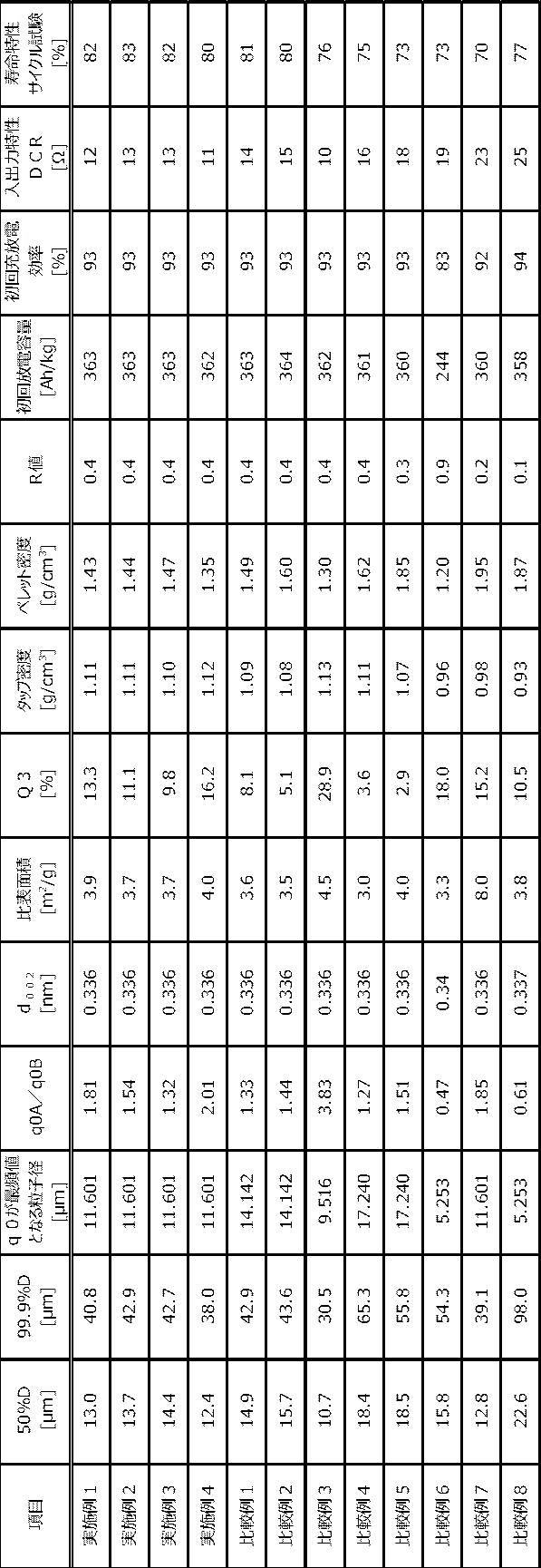
- Example 2 A carbon material was produced in the same manner as in Example 1 except that the composite material 1 and the composite material 2 were mixed so that the mass ratio was 4: 6 (composite material 1: composite material 2), and the characteristics thereof were examined. Moreover, the coin battery was produced and the performance was evaluated. The results are shown in Table 2.
- Example 3 A carbon material was prepared in the same manner as in Example 1 except that the composite material 1 and the composite material 2 were mixed so that the mass ratio was 3: 7 (composite material 1: composite material 2), and the characteristics thereof were examined. Moreover, the coin battery was produced and the performance was evaluated. The results are shown in Table 2.
- Example 4 A carbon material was prepared in the same manner as in Example 1 except that the composite material 1 and the composite material 2 were mixed so that the mass ratio was 6: 4 (composite material 1: composite material 2), and the characteristics thereof were examined. Moreover, the coin battery was produced and the performance was evaluated. The results are shown in Table 2.
- Example 1 A carbon material was produced in the same manner as in Example 1 except that the composite material 1 and the composite material 2 were mixed so that the mass ratio was 2: 8 (composite material 1: composite material 2), and the characteristics thereof were examined. Moreover, the coin battery was produced and the performance was evaluated. The results are shown in Table 2.
- Example 2 A carbon material was produced in the same manner as in Example 1 except that only the composite material 2 was used, and the characteristics thereof were examined. Moreover, the coin battery was produced and the performance was evaluated. The results are shown in Table 2.
- Example 3 A carbon material was produced in the same manner as in Example 1 except that only the composite material 1 was used, and its characteristics were examined. Moreover, the coin battery was produced and the performance was evaluated. The results are shown in Table 2.
- composite material 3 was obtained.
- a carbon material was produced in the same manner as in Example 1 except that the composite material 3 and the composite material 2 were mixed so that the mass ratio was 5: 5 (composite material 3: composite material 2), and the characteristics thereof were examined. Moreover, the coin battery was produced and the performance was evaluated. The results are shown in Table 2.
- the composite material was the same as the composite material 1 except that a mixture obtained by mixing 100 parts by mass of the carbon particles and 20 parts by mass of polyvinyl alcohol (degree of polymerization 1700, complete saponification type, carbonization rate 15% by mass) was used. 4 was obtained.
- a carbon material was produced in the same manner as in Example 1 except that the composite material 4 and the composite material 2 were mixed so that the mass ratio was 5: 5 (composite material 4: composite material 2), and the characteristics thereof were examined. Moreover, the coin battery was produced and the performance was evaluated. The results are shown in Table 2.
- the obtained lump was pulverized with a pin mill and then molded into a block shape having a density of 1.52 g / cm 3 with a mold press.
- the obtained block was fired at a maximum temperature of 800 ° C. in a muffle furnace, and then graphitized at 2900 ° C. in an autolysis gas atmosphere in an Atchison furnace.
- the graphitized block was roughly crushed with a hammer, and a graphite powder having an average particle size of 30 ⁇ m was obtained with a pin mill. Further, this graphite powder was processed for 10 minutes using a spheroidizing apparatus (manufactured by Hosokawa Micron, Faculty) at a grinding rotation speed of 1800 rotations / minute (rpm) and a classification rotation speed of 7000 rotations / minute (rpm). Chemical artificial graphite powder was prepared. This spheroidized artificial graphite powder was passed through a 200-mesh sieve to obtain a carbon material under the sieve. The characteristics of this carbon material were examined in the same manner as in Example 1. Moreover, the coin battery was produced and the performance was evaluated. The results are shown in Table 2.
- the lithium ion secondary batteries of Examples 1 to 4 manufactured using the negative electrode material containing the carbon material of the present embodiment were able to input / output while maintaining high charge / discharge efficiency. Excellent properties and life characteristics.
Landscapes
- Chemical & Material Sciences (AREA)
- Chemical Kinetics & Catalysis (AREA)
- Electrochemistry (AREA)
- General Chemical & Material Sciences (AREA)
- Engineering & Computer Science (AREA)
- Inorganic Chemistry (AREA)
- Materials Engineering (AREA)
- Manufacturing & Machinery (AREA)
- Battery Electrode And Active Subsutance (AREA)
- Secondary Cells (AREA)
- Carbon And Carbon Compounds (AREA)
Abstract
Description
リチウムイオン二次電池が1991年に製品化されて以来、その高エネルギー密度化と入出力特性のさらなる向上は、今なお強く望まれている。そのための手段として、リチウムイオン二次電池の負極に含まれる負極材を改良する技術は重要な位置を占めている(例えば、特許文献1及び特許文献2参照)。
黒鉛は炭素原子の六角網面が規則正しく積層した構造を有し、積層した網面の端部よりリチウムイオンの挿入・脱離反応が進行して充放電を行う。
また、非晶質炭素は、六角網面の積層が不規則であるか、網目構造を有しないため、リチウムイオンの挿入・脱離反応は全表面で進行することとなり、入出力特性に優れたリチウムイオンが得られやすい。また、非晶質炭素は、黒鉛とは対照的に、結晶性が低く、電解液との反応を低く抑えることができ、寿命特性に優れるといった特徴を有する。
<1>X線回折法より求めた平均面間隔d002が0.335nm~0.339nmであり、77Kでの窒素吸着測定より求めた比表面積が0.5m2/g~6.0m2/gであり、かつ下記(1)及び(2)を満たす炭素材料を含む、リチウムイオン二次電池用負極材。
(1)個数基準の粒度分布において、差分の相対粒子量q0が最頻値となるときの粒子径が11.601μm以下である。
(2)個数基準の粒度分布において、粒子径11.601μmのときの差分の相対粒子量q0Aと、粒子径7.806μmのときの差分の相対粒子量q0Bとの比(q0A/q0B)が1.20~3.00である。
(1)個数基準の粒度分布において、差分の相対粒子量q0が最頻値となるときの粒子径が11.601μm以下である。
(2)個数基準の粒度分布において、粒子径11.601μmのときの差分の相対粒子量q0Aと、粒子径7.806μmのときの差分の相対粒子量q0Bとの比(q0A/q0B)が1.20~3.00である。
(1)個数基準の粒度分布において、差分の相対粒子量q0が最頻値となるときの粒子径が11.601μm以下である。
(2)個数基準の粒度分布において、粒子径11.601μmのときの差分の相対粒子量q0Aと、粒子径7.806μmのときの差分の相対粒子量q0Bとの比(q0A/q0B)が1.20~3.00である。
本明細書において「~」を用いて示された数値範囲には、「~」の前後に記載される数値がそれぞれ最小値及び最大値として含まれる。
本明細書中に段階的に記載されている数値範囲において、一つの数値範囲で記載された上限値又は下限値は、他の段階的な記載の数値範囲の上限値又は下限値に置き換えてもよい。また、本明細書中に記載されている数値範囲において、その数値範囲の上限値又は下限値は、実施例に示されている値に置き換えてもよい。
本明細書において組成物中の各成分の含有率又は含有量は、組成物中に各成分に該当する物質が複数種存在する場合、特に断らない限り、組成物中に存在する当該複数種の物質の合計の含有率又は含有量を意味する。
本明細書において組成物中の各成分の粒子径は、組成物中に各成分に該当する粒子が複数種存在する場合、特に断らない限り、組成物中に存在する当該複数種の粒子の混合物についての値を意味する。
本明細書において「層」又は「膜」との語には、当該層又は膜が存在する領域を観察したときに、当該領域の全体に形成されている場合に加え、当該領域の一部にのみ形成されている場合も含まれる。
本明細書において「積層」との語は、層を積み重ねることを示し、二以上の層が結合されていてもよく、二以上の層が着脱可能であってもよい。
本実施形態のリチウムイオン二次電池用負極材(以下、単に「負極材」と呼ぶ場合がある)は、X線回折法より求めた平均面間隔d002が0.335nm~0.339nmであり、77Kでの窒素吸着測定より求めた比表面積が0.5m2/g~6.0m2/gであり、かつ下記(1)及び(2)を満たす炭素材料を含む。
(1)個数基準の粒度分布において、差分の相対粒子量q0が最頻値となるときの粒子径が11.601μm以下である。
(2)個数基準の粒度分布において、粒子径11.601μmのときの差分の相対粒子量q0Aと、粒子径7.806μmのときの差分の相対粒子量q0Bとの比(q0A/q0B)が1.20~3.00である。
炭素材料のX線回折法より求めた平均面間隔d002は、0.335nm~0.339nmである。
平均面間隔d002の値は、0.3354nmが黒鉛結晶の理論値であり、この値に近いほどエネルギー密度が大きくなる傾向にある。平均面間隔d002の値が上記範囲内の場合、優れたリチウムイオン二次電池の初回充放電効率とエネルギー密度が得られる傾向にある。
炭素材料の平均面間隔d002の値は、例えば、炭素材料に対して行う熱処理の温度を高くすることで小さくなる傾向にあるため、この性質を利用して平均面間隔d002を上記範囲内に調節することができる。
炭素材料のN2比表面積が上記範囲内であると、入出力特性と初回効率のバランスが良好に維持される傾向にある。
炭素材料のN2比表面積は、77Kでの窒素吸着測定より得た吸着等温線からBET法を用いて求めることができる。
N2比表面積は、例えば、炭素材料の体積平均粒子径を大きくする、炭素材料に対して行う熱処理の温度を高くする、炭素材料の表面を改質する等の方法により値を小さくできる傾向にあるため、この性質を利用してN2比表面積を上記範囲内に設定することができる。
q0A/q0Bの値が1.20未満であると、入出力特性が低下する傾向にある。
q0A/q0Bの値が3.00を超えると、炭素材料の粒子同士の接触が悪くなり、リチウムイオン二次電池の寿命特性が低下する傾向にある。
入出力特性と寿命特性の観点からは、q0A/q0Bの値は、1.20~2.20の範囲であることが好ましく、1.25~2.10の範囲であることがより好ましい。
表1には、実施例2で用いた炭素材料の個数基準における差分の相対粒子量q0の値と粒子径をあわせて示す。

粒子径が9.516μmのときの積算値Q3が全体の4.0%以上であると、炭素材料中に含まれる微小な粒子により粒子間の接触点が充分に確保され、リチウムイオン二次電池の寿命特性が向上する傾向にある。
炭素材料の体積平均粒子径が1μm以上であると、比表面積が大きすぎてリチウムイオン二次電池の初回充放電効率が低下することが抑制される傾向にある。一方、炭素材料の体積平均粒子径が20μm以下であると、粒子径が大きすぎて粒子表面から内部へのLiの拡散距離が長くなり、リチウムイオン二次電池の入出力特性が低下することが抑制される傾向にある。
炭素材料の最大粒子径が63μm以下であると、電極を作製する際に極板を薄膜化しやすく、入出力特性への影響が抑制される傾向にある。
測定回数:1回
測定間隔:2秒
平均回数:64回
測定吸光度範囲:0.01~0.2
(任意粒子径・%テーブル設定)
範囲:0.1μm~2000μm
分割数:50
このような炭素材料の組み合わせとしては、体積平均粒子径が8μm~12μmの炭素材料と体積平均粒子径が14μm~18μmの炭素材料の組み合わせ、体積平均粒子径が9μm~11μmの炭素材料と体積平均粒子径が15μm~17μmの炭素材料の組み合わせ等が挙げられる。
粒子径の異なる炭素材料を2種組み合わせる場合の比率としては、例えば、質量比で7:3~3:7の範囲内、質量比で6:4~4:6の範囲内等が挙げられる。
炭素材料のタップ密度が0.90g/cm3以上であると、負極を作製する際に用いる結着剤等の有機物の量を少なくでき、リチウムイオン二次電池のエネルギー密度が大きくなる傾向にある。一方、炭素材料のタップ密度が2.00g/cm3以下であると、入出力特性が良好となる傾向にある。
黒鉛材料のアスペクト比は、例えば、フロー式粒子像分析装置を用いて測定することができる。フロー式粒子像分析装置としては、シスメックス株式会社の「FPIA-3000」等が挙げられる。
金属成分としては、高容量化のため必要に応じて、Al、Si、Ga、Ge、In、Sn、Sb、Ag等のリチウムと合金化する元素からなる金属の粉末、Al、Si、Ga、Ge、In、Sn、Sb、Ag等のリチウムと合金化する元素を少なくとも含む多元系合金の粉末、リチウム合金の粉末などが挙げられる。金属成分は、1種を単独で用いても、2種以上を組み合わせて用いてもよい。また、負極材が金属成分を含む場合、金属成分は炭素材料とは別に添加されても、炭素材料と複合化した状態で添加されてもよい。
本実施形態のリチウムイオン二次電池用負極材は、X線回折法より求めた平均面間隔d002が0.335nm~0.339nmであり、ラマン分光測定のR値が0.1~1.0であり、かつ下記(1)及び(2)を満たす炭素材料を含む。
(1)個数基準の粒度分布において、差分の相対粒子量q0が最頻値となるときの粒子径が11.601μm以下である。
(2)個数基準の粒度分布において、粒子径11.601μmのときの差分の相対粒子量q0Aと、粒子径7.806μmのときの差分の相対粒子量q0Bとの比(q0A/q0B)が1.20~3.00である。
本実施形態のリチウムイオン二次電池用負極材は、X線回折法により求めた平均面間隔d002が0.335nm~0.339nmであり、核となる第一の炭素相と、前記第一の炭素相の表面の少なくとも一部に配置される第一の炭素相とは異なる第二の炭素相と、を含み、かつ下記(1)及び(2)を満たす炭素材料を含む。
(1)個数基準の粒度分布において、差分の相対粒子量q0が最頻値となるときの粒子径が11.601μm以下である。
(2)個数基準の粒度分布において、粒子径11.601μmのときの差分の相対粒子量q0Aと、粒子径7.806μmのときの差分の相対粒子量q0Bとの比(q0A/q0B)が1.20~3.00である。
本実施形態の負極材の製造方法に特に制限はなく、負極材の製造に通常用いられている方法を採用することができる。
本実施形態のリチウムイオン二次電池用負極は、上述した負極材を含む負極材層と、集電体と、を含む。これにより、高い充放電効率を維持しながら、入出力特性と寿命特性にも優れるリチウムイオン二次電池を構成することが可能となる。リチウムイオン二次電池用負極は、上述した負極材を含む負極材層及び集電体の他、必要に応じて他の構成要素を含んでもよい。
負極組成物に含まれる有機系結着剤の量は特に制限されないが、負極材と有機系結着剤の合計100質量部に対して0.5質量部~20質量部であることが好ましい。
本実施形態のリチウムイオン二次電池は、上述したリチウムイオン二次電池用負極と、正極と、電解質と、を含む。リチウムイオン二次電池は、例えば、リチウムイオン二次電池用負極と正極とをセパレータを介して対向するように容器内に配置し、電解質を溶媒に溶解して調製した電解液を容器内に注入することにより得ることができる。
正極活物質としては、コバルト酸リチウム(LiCoO2)、ニッケル酸リチウム(LiNiO2)、マンガン酸リチウム(LiMnO2)、コバルト酸リチウムにおいてコバルトの少なくとも一部がニッケル及びマンガンの少なくとも一方で置換された複酸化物(LiCoxNiyMnzO2、x+y+z=1)、これらの化合物においてコバルト、ニッケル及びマンガンの少なくとも一部が添加元素M’で置換された複酸化物(LiCoaNibMncM’dO2、a+b+c+d=1、M’:Al、Mg、Ti、Zr又はGe)、リチウムマンガンスピネル(LiMn2O4)、リチウムバナジウム化合物、V2O5、V6O13、VO2、MnO2、TiO2、MoV2O8、TiS2、V2S5、VS2、MoS2、MoS3、Cr3O8、Cr2O5、及びオリビン型LiMPO4(M:Co、Ni、Mn、Fe)が挙げられる。
その他の材料としては、ポリアセチレン、ポリアニリン、ポリピロール、ポリチオフェン、ポリアセン等の導電性ポリマー、多孔質炭素などが挙げられる。
電解質を溶解する溶媒としては、エチレンカーボネート、フルオロエチレンカーボネート、クロロエチレンカーボネート、プロピレンカーボネート、ブチレンカーボネート、ビニレンカーボネート、シクロペンタノン、シクロヘキシルベンゼン、スルホラン、プロパンスルトン、3-メチルスルホラン、2,4-ジメチルスルホラン、3-メチル-1,3-オキサゾリジン-2-オン、γ-ブチロラクトン、ジメチルカーボネート、ジエチルカーボネート、エチルメチルカーボネート、メチルプロピルカーボネート、ブチルメチルカーボネート、エチルプロピルカーボネート、ブチルエチルカーボネート、ジプロピルカーボネート、1,2-ジメトキシエタン、テトラヒドロフラン、2-メチルテトラヒドロフラン、1,3-ジオキソラン、酢酸メチル、酢酸エチル、トリメチルリン酸エステル、トリエチルリン酸エステル等の非水系溶媒が挙げられる。
体積平均粒子径が10μmの球状天然黒鉛(d002=0.336nm、平均アスペクト比=0.8)100質量部と、コールタールピッチ(軟化点98℃、残炭率(炭化率)50%)5質量部とを混合して得た混合物を、回転翼を配置したシリンダー内に入れ、シリンダーの内壁と回転翼の間で擦り合わせることにより、球状天然黒鉛の表面にコールタールピッチを付着させた。擦り合わせの工程は24kWの負荷で5分間行った(負荷:1800kJ/kg)。次いで窒素流通下、20℃/時間の昇温速度で1000℃まで昇温し、1時間保持してコールタールピッチを炭素化した。その後、カッターミルで解砕し、300メッシュ篩で篩分けを行い、その篩下を複合材料1として得た。
炭素材料を石英製の試料ホルダーの凹部分に充填し、測定ステージにセットした。以下の測定条件において広角X線回折装置(株式会社リガク製)で測定を行った。
線源:CuKα線(波長=0.15418nm)
出力:40kV、20mA
サンプリング幅:0.010°
走査範囲:10°~35°
スキャンスピード:0.5°/min
炭素材料について、高速比表面積/細孔分布測定装置(MICROMERITICS社の「ASAP2010」)を用いて液体窒素温度(77K)での窒素吸着を多点法で測定し、BET法(相対圧範囲:0.05~0.2)より算出した。
炭素材料を界面活性剤と共に精製水中に分散させた溶液を、レーザー回折式粒度分布測定装置(株式会社島津製作所の「SALD-3000J」)の試料水槽に入れ、ポンプで循環させながら1分間超音波をかけて、以下の測定条件においてレーザー回折式で測定した。この際、出力条件を個数又は体積基準に設定して下記(1)~(5)に該当する値を調べた。
測定回数:1回
測定間隔:2秒
平均回数:64回
測定吸光度範囲:0.01~0.2
(任意粒子径・%テーブル設定)
範囲:0.1~2000μm
分割数:50
容量100cm3のメスシリンダーに炭素材料100cm3をゆっくり投入し、メスシリンダーに栓をした。このメスシリンダーを5cmの高さから250回落下させた後の炭素材料の質量及び容積から求められる値をタップ密度とした。
13mm径の成型器(Carver社の13mm pellet die 型番3619)に炭素材料1.00gを投入し、油圧プレス機(Carver社の「Carver Standard Press」)にて1.0tの圧力で加圧した後の炭素材料の厚み及び断面積から求められる体積を炭素材料の質量で除した値をペレット密度とした。
炭素材料の平均アスペクト比は、フロー式粒子像分析装置(シスメックス株式会社の「FPIA-3000」)を用いて求めた。
作製した炭素材料98質量部に対し、増粘剤としてCMC(カルボキシメチルセルロース、第一工業製薬株式会社の「セロゲンWS-C」)の濃度が2質量%の水溶液をCMCの固形分で1質量部となるように加え、10分間混練を行った。次いで、混練物中の固形分濃度(負極材とCMCの合計)が40質量%~50質量%となるように精製水を加え、10分間混練を行った。次いで、結着剤としてSBR(日本ゼオン株式会社の「BM-400B」)の濃度が40質量%の水分散液をSBRの固形分で1質量部となるように加え、10分間混合してペースト状の負極材組成物を作製した。この負極材組成物を厚さ40μmの電解銅箔に厚さ200μmのマスクを用いて直径9.5mmの円形となるよう塗布した。さらに、105℃で乾燥して水分を除去し、試料電極(負極)を作製した。
初回充放電効率の測定に用いた負極材組成物と同様の方法で作製した負極材組成物を、厚さ40μmの電解銅箔に単位面積当りの塗布量が9.0mg/cm2となるようにクリアランスを調整したコンマコーターで塗工した。その後、ハンドプレスで電極密度を1.5g/cm3に調整した。この電極を直径14mmの円盤状に打ち抜き、試料電極(負極)を作製した。この試料電極を用いた以外は初回充放電効率の測定と同様にして、コイン電池を作製した。
(1)0.48mAの定電流で0V(Vvs.Li/Li+)まで充電し、次いで0Vの定電圧で電流が0.048mAになるまで充電した。
(2)30分の休止時間後に、0.48mAの定電流で1.5V(Vvs.Li/Li+)まで放電する1サイクル試験を行い、放電容量を測定した。
(3)4.8mAの定電流で0V(Vvs.Li/Li+)まで充電し、0Vの定電圧で電流が0.48mAになるまで充電した。
(4)30分の休止時間後に、4.8mAの定電流で1.5V(Vvs.Li/Li+)まで放電した。
(5)上記(3)及び(4)の充放電サイクル試験を50サイクル行った。
上記のサイクルを50サイクル繰り返したときの1サイクル目からの放電容量維持率(=50サイクル目放電容量/1サイクル目放電容量×100)を測定した。放電容量維持率が高いほど、寿命特性に優れていると判断することができる。
寿命特性と同等の方法でコイン電池を作製し、下記手順で入出力特性の評価を行った。
(1)0.96mAの定電流で0V(Vvs.Li/Li+)まで充電し、次いで電流値が0.096mAになるまで0Vで定電圧充電を行った。
(2)30分の休止時間後に、0.96mAの定電流で1.5V(Vvs.Li/Li+)まで放電した。
(3)0.96mAの定電流で容量の半分まで充電を行った。
(4)4.8mA、14.4mA、24mAの電流値で10秒間放電を行い、その際の電圧降下(ΔV)を確認した。それぞれの電流値での試験の間には30分間の休止時間を置いた。
各電流値に対してΔVをプロットし、その傾きを抵抗値(Ω)とした。この値が小さいほど、入出力特性に優れると判断することができる。
複合材料1と複合材料2を質量比が4:6(複合材料1:複合材料2)となるように混合した以外は実施例1と同様にして炭素材料を作製し、その特性を調べた。また、コイン電池を作製してその性能を評価した。結果を表2に示す。
複合材料1と複合材料2を質量比が3:7(複合材料1:複合材料2)となるように混合した以外は実施例1と同様にして炭素材料を作製し、その特性を調べた。また、コイン電池を作製してその性能を評価した。結果を表2に示す。
複合材料1と複合材料2を質量比が6:4(複合材料1:複合材料2)となるように混合した以外は実施例1と同様にして炭素材料を作製し、その特性を調べた。また、コイン電池を作製してその性能を評価した。結果を表2に示す。
複合材料1と複合材料2を質量比が2:8(複合材料1:複合材料2)となるように混合した以外は実施例1と同様にして炭素材料を作製し、その特性を調べた。また、コイン電池を作製してその性能を評価した。結果を表2に示す。
複合材料2のみを用いた以外は実施例1と同様にして炭素材料を作製し、その特性を調べた。また、コイン電池を作製してその性能を評価した。結果を表2に示す。
複合材料1のみを用いた以外は実施例1と同様にして炭素材料を作製し、その特性を調べた。また、コイン電池を作製してその性能を評価した。結果を表2に示す。
体積平均粒子径が10μmの球状天然黒鉛の代わりに体積平均粒子径が22μmの球状天然黒鉛(d002=0.336nm、平均アスペクト比=0.7)100質量部を用いた以外は複合材料1と同様にして、複合材料3を得た。
複合材料3と複合材料2を質量比が5:5(複合材料3:複合材料2)となるように混合した以外は実施例1と同様にして炭素材料を作製し、その特性を調べた。また、コイン電池を作製してその性能を評価した。結果を表2に示す。
体積平均粒子径が22μmの球状天然黒鉛(d002=0.336nm、平均アスペクト比=0.7)を300メッシュの篩に通し、得られた篩下と複合材料2を質量比が5:5(篩下:複合材料2)となるように混合した以外は実施例1と同様にして炭素材料を作製し、その特性を調べた。また、コイン電池を作製してその性能を評価した。結果を表2に示す。
石炭系コールタールをオートクレーブにより400℃で熱処理し、生コークスを得た。この生コークスを粉砕した後、1200℃の不活性雰囲気中でカ焼を行い、コークス塊を得た。このコークス塊を分級機付きの衝撃粉砕機を用いて平均粒子径15μmに粉砕後、200メッシュの篩に通し、篩下を炭素粒子(d002=0.342nm)として得た。この炭素粒子100質量部とポリビニルアルコール(重合度1700、完全けん化型、炭化率15質量%)20質量部を混合して得た混合物を用いたこと以外は複合材料1と同様にして、複合材料4を得た。
複合材料4と複合材料2を質量比が5:5(複合材料4:複合材料2)となるように混合した以外は実施例1と同様にして炭素材料を作製し、その特性を調べた。また、コイン電池を作製してその性能を評価した。結果を表2に示す。
体積平均粒子径10μmの球状天然黒鉛(d002=0.336nm、平均アスペクト比=0.8)と体積平均粒子径16μmの球状天然黒鉛(d002=0.336nm、平均アスペクト比=0.8)を質量比が5:5となるように混合した以外は実施例1と同様にして炭素材料を作製し、その特性を調べた。また、コイン電池を作製してその性能を評価した。結果を表2に示す。
比較例6で作製した炭素粒子(d002=0.342nm)100質量部とコールタールピッチ30質量部と酸化鉄粉末5質量部を250℃で1時間混合した。得られた塊状物をピンミルで粉砕した後、型込みプレスで、密度1.52g/cm3のブロック状に成形加工した。得られたブロックをマッフル炉で最高温度800℃にて焼成したのち、アチソン炉で自己分解ガス雰囲気下、2900℃にて黒鉛化を行った。次いで、黒鉛化したブロックを、ハンマーで粗砕した後、ピンミルで平均粒子径30μmの黒鉛粉末を得た。さらにこの黒鉛粉末を、球形化処理装置(ホソカワミクロン製、ファカルティ)を使用し、粉砕回転数1800回転/分(rpm)、分級回転数7000回転/分(rpm)で10分間の処理を行い、球形化人造黒鉛粉末を作製した。この球形化人造黒鉛粉末を200メッシュの篩に通し、篩下を炭素材料として得た。この炭素材料の特性を実施例1と同様にして調べた。また、コイン電池を作製してその性能を評価した。結果を表2に示す。
Claims (10)
- X線回折法より求めた平均面間隔d002が0.335nm~0.339nmであり、77Kでの窒素吸着測定より求めた比表面積が0.5m2/g~6.0m2/gであり、かつ下記(1)及び(2)を満たす炭素材料を含む、リチウムイオン二次電池用負極材。
(1)個数基準の粒度分布において、差分の相対粒子量q0が最頻値となるときの粒子径が11.601μm以下である。
(2)個数基準の粒度分布において、粒子径11.601μmのときの差分の相対粒子量q0Aと、粒子径7.806μmのときの差分の相対粒子量q0Bとの比(q0A/q0B)が1.20~3.00である。 - X線回折法より求めた平均面間隔d002が0.335nm~0.339nmであり、ラマン分光測定のR値が0.1~1.0であり、かつ下記(1)及び(2)を満たす炭素材料を含む、リチウムイオン二次電池用負極材。
(1)個数基準の粒度分布において、差分の相対粒子量q0が最頻値となるときの粒子径が11.601μm以下である。
(2)個数基準の粒度分布において、粒子径11.601μmのときの差分の相対粒子量q0Aと、粒子径7.806μmのときの差分の相対粒子量q0Bとの比(q0A/q0B)が1.20~3.00である。 - X線回折法より求めた平均面間隔d002が0.335nm~0.339nmであり、核となる第一の炭素相と、前記第一の炭素相の表面の少なくとも一部に配置される第一の炭素相とは異なる第二の炭素相と、を含み、かつ下記(1)及び(2)を満たす炭素材料を含む、リチウムイオン二次電池用負極材。
(1)個数基準の粒度分布において、差分の相対粒子量q0が最頻値となるときの粒子径が11.601μm以下である。
(2)個数基準の粒度分布において、粒子径11.601μmのときの差分の相対粒子量q0Aと、粒子径7.806μmのときの差分の相対粒子量q0Bとの比(q0A/q0B)が1.20~3.00である。 - 前記炭素材料は、体積基準の粒度分布において、小粒子径側から体積累積分布曲線を描いた場合に、粒子径が9.516μmのときの積算値Q3が全体の4.0%以上である請求項1~請求項3のいずれか1項に記載のリチウムイオン二次電池用負極材。
- 前記炭素材料は、体積基準の粒度分布において、小粒子径側から体積累積分布曲線を描いた場合に、累積が50%となるときの粒子径(50%D)が1μm~20μmである請求項1~請求項4のいずれか1項に記載のリチウムイオン二次電池用負極材。
- 前記炭素材料は、体積基準の粒度分布において、小粒子径側から体積累積分布曲線を描いた場合に、累積が99.9%となるときの粒子径(99.9%D)が63μm以下である請求項1~請求項5のいずれか1項に記載のリチウムイオン二次電池用負極材。
- 前記炭素材料は、タップ密度が0.90g/cm3~2.00g/cm3である請求項1~請求項6のいずれか1項に記載のリチウムイオン二次電池用負極材。
- 前記炭素材料は、ペレット密度が1.55g/cm3以下である請求項1~請求項7のいずれか1項に記載のリチウムイオン二次電池用負極材。
- 請求項1~請求項8のいずれか1項に記載のリチウムイオン二次電池用負極材を含む負極材層と、集電体と、を含むリチウムイオン二次電池用負極。
- 請求項9に記載のリチウムイオン二次電池用負極と、正極と、電解質と、を含むリチウムイオン二次電池。
Priority Applications (6)
| Application Number | Priority Date | Filing Date | Title |
|---|---|---|---|
| KR1020197014057A KR102671321B1 (ko) | 2016-11-14 | 2016-11-14 | 리튬이온 2차전지용 음극재, 리튬이온 2차전지용 음극 및 리튬이온 2차전지 |
| JP2018550011A JP6922927B2 (ja) | 2016-11-14 | 2016-11-14 | リチウムイオン二次電池用負極材、リチウムイオン二次電池用負極及びリチウムイオン二次電池 |
| PCT/JP2016/083714 WO2018087928A1 (ja) | 2016-11-14 | 2016-11-14 | リチウムイオン二次電池用負極材、リチウムイオン二次電池用負極及びリチウムイオン二次電池 |
| CN201680090827.3A CN109952672B (zh) | 2016-11-14 | 2016-11-14 | 锂离子二次电池用负极材、锂离子二次电池用负极和锂离子二次电池 |
| CN202210750544.4A CN114883558B (zh) | 2016-11-14 | 2016-11-14 | 锂离子二次电池用负极材、锂离子二次电池用负极和锂离子二次电池 |
| TW106139157A TWI752112B (zh) | 2016-11-14 | 2017-11-13 | 鋰離子二次電池用負極材料、鋰離子二次電池用負極及鋰離子二次電池 |
Applications Claiming Priority (1)
| Application Number | Priority Date | Filing Date | Title |
|---|---|---|---|
| PCT/JP2016/083714 WO2018087928A1 (ja) | 2016-11-14 | 2016-11-14 | リチウムイオン二次電池用負極材、リチウムイオン二次電池用負極及びリチウムイオン二次電池 |
Publications (1)
| Publication Number | Publication Date |
|---|---|
| WO2018087928A1 true WO2018087928A1 (ja) | 2018-05-17 |
Family
ID=62109485
Family Applications (1)
| Application Number | Title | Priority Date | Filing Date |
|---|---|---|---|
| PCT/JP2016/083714 Ceased WO2018087928A1 (ja) | 2016-11-14 | 2016-11-14 | リチウムイオン二次電池用負極材、リチウムイオン二次電池用負極及びリチウムイオン二次電池 |
Country Status (5)
| Country | Link |
|---|---|
| JP (1) | JP6922927B2 (ja) |
| KR (1) | KR102671321B1 (ja) |
| CN (2) | CN109952672B (ja) |
| TW (1) | TWI752112B (ja) |
| WO (1) | WO2018087928A1 (ja) |
Cited By (3)
| Publication number | Priority date | Publication date | Assignee | Title |
|---|---|---|---|---|
| JPWO2021019727A1 (ja) * | 2019-07-31 | 2021-02-04 | ||
| CN113228344A (zh) * | 2019-01-04 | 2021-08-06 | 昭和电工材料株式会社 | 锂离子二次电池用负极材、锂离子二次电池用负极材的制造方法、锂离子二次电池用负极及锂离子二次电池 |
| US11837728B2 (en) | 2020-08-05 | 2023-12-05 | Sk On Co., Ltd. | Anode active material and lithium secondary battery including the same |
Families Citing this family (1)
| Publication number | Priority date | Publication date | Assignee | Title |
|---|---|---|---|---|
| CN115791543B (zh) * | 2022-10-21 | 2025-07-11 | 江苏正力新能电池技术股份有限公司 | 一种电池首次效率的评估方法 |
Citations (7)
| Publication number | Priority date | Publication date | Assignee | Title |
|---|---|---|---|---|
| WO2003063274A1 (fr) * | 2002-01-25 | 2003-07-31 | Toyo Tanso Co., Ltd. | Matiere d'electrode negative destinee a un accumulateur au lithium-ion |
| JP2005040068A (ja) * | 2003-07-23 | 2005-02-17 | Ito En Ltd | コーヒー飲料の製造方法 |
| WO2006025376A1 (ja) * | 2004-08-30 | 2006-03-09 | Mitsubishi Chemical Corporation | 非水系二次電池用負極材料、非水系二次電池用負極、および非水系二次電池 |
| JP2015069818A (ja) * | 2013-09-27 | 2015-04-13 | 昭和電工株式会社 | コークス、電極活物質及び電池 |
| JP2015082381A (ja) * | 2013-10-22 | 2015-04-27 | トヨタ自動車株式会社 | 非水電解質二次電池 |
| JP2015110506A (ja) * | 2013-11-07 | 2015-06-18 | Jfeケミカル株式会社 | 炭素質被覆黒鉛粒子の製造方法、リチウムイオン二次電池用負極およびリチウムイオン二次電池 |
| JP2015185443A (ja) * | 2014-03-25 | 2015-10-22 | 三菱化学株式会社 | 非水系二次電池用炭素材、及び、非水系二次電池 |
Family Cites Families (23)
| Publication number | Priority date | Publication date | Assignee | Title |
|---|---|---|---|---|
| JP3335366B2 (ja) | 1991-06-20 | 2002-10-15 | 三菱化学株式会社 | 二次電池用電極 |
| JP3395200B2 (ja) | 1992-04-28 | 2003-04-07 | 三洋電機株式会社 | 非水系二次電池 |
| JP3440638B2 (ja) * | 1995-07-12 | 2003-08-25 | 松下電器産業株式会社 | 非水電解液二次電池 |
| KR100575971B1 (ko) * | 2002-03-27 | 2006-05-02 | 제이에프이 케미칼 가부시키가이샤 | 메소상 소구체의 흑연화물, 그를 사용한 음극 재료, 음극및 리튬 이온 2차 전지 |
| EP2259375B1 (en) * | 2003-02-27 | 2012-05-16 | Mitsubishi Chemical Corporation | Nonaqueous electrolytic solution and lithium secondary battery |
| KR100639888B1 (ko) * | 2004-05-04 | 2006-10-30 | 주식회사 소디프신소재 | 신규한 흑연 소구체 및 이를 이용한 탄소 재료 |
| JP2008305661A (ja) * | 2007-06-07 | 2008-12-18 | Tokai Carbon Co Ltd | リチウムイオン二次電池用負極材とその製造方法 |
| JP2008305722A (ja) * | 2007-06-08 | 2008-12-18 | Tokai Carbon Co Ltd | リチウムイオン二次電池用負極材とその製造方法 |
| CN101106191A (zh) * | 2007-07-26 | 2008-01-16 | 辽宁工程技术大学 | 复合石墨负极材料的制备方法及使用该材料的锂离子电池 |
| CN101412510A (zh) * | 2007-10-15 | 2009-04-22 | 台湾松下能源股份有限公司 | 用于锂二次电池的复合石墨及其制造方法 |
| KR100945619B1 (ko) * | 2008-04-23 | 2010-03-04 | 엘에스엠트론 주식회사 | 2차 전지용 음극 활물질, 이를 포함하는 2차 전지 및 그제조 방법 |
| CN102414879B (zh) * | 2009-04-27 | 2015-04-15 | 加拿大巴斯姆有限公司 | 用于锂电化学电池的电极和电极材料 |
| US9876221B2 (en) * | 2010-05-14 | 2018-01-23 | Samsung Sdi Co., Ltd. | Negative active material for rechargeable lithium battery and rechargeable lithium battery including same |
| EP2600449A4 (en) * | 2010-07-30 | 2016-09-28 | Hitachi Chemical Co Ltd | MINUS POLYMER FOR A LITHIUMION SECONDARY BATTERY, MINUS POLICE FOR A LITHIUMION SECONDARY BATTERY, AND A LITHIUMION SECONDARY BATTERY |
| JP6121645B2 (ja) * | 2010-09-16 | 2017-04-26 | 三菱化学株式会社 | 非水電解液二次電池用負極材及びこれを用いた負極並びに非水電解液二次電池 |
| JP2012216532A (ja) * | 2011-03-29 | 2012-11-08 | Mitsubishi Chemicals Corp | 非水系二次電池用負極材料、これを用いた負極及び非水系二次電池 |
| CN103492316B (zh) * | 2011-12-09 | 2015-03-18 | 昭和电工株式会社 | 复合石墨颗粒及其用途 |
| JP5987439B2 (ja) * | 2012-04-19 | 2016-09-07 | 日立化成株式会社 | リチウムイオン二次電池用負極活物質及びリチウムイオン二次電池 |
| JP2014089855A (ja) * | 2012-10-30 | 2014-05-15 | Hitachi Maxell Ltd | 非水二次電池用負極活物質および非水二次電池 |
| WO2015190833A1 (ko) * | 2014-06-13 | 2015-12-17 | 주식회사 엘지화학 | 음극 활물질 및 이의 제조방법 |
| WO2016136803A1 (ja) * | 2015-02-25 | 2016-09-01 | 新日鉄住金化学株式会社 | リチウムイオン二次電池負極用活物質、それを用いた二次電池負極及び二次電池 |
| WO2016153255A1 (ko) * | 2015-03-23 | 2016-09-29 | 주식회사 엘지화학 | 음극 활물질 및 이의 제조방법 |
| CN106058211B (zh) * | 2016-08-03 | 2019-07-09 | 深圳市贝特瑞新能源材料股份有限公司 | 一种天然石墨复合材料、其制备方法和锂离子电池 |
-
2016
- 2016-11-14 CN CN201680090827.3A patent/CN109952672B/zh active Active
- 2016-11-14 JP JP2018550011A patent/JP6922927B2/ja active Active
- 2016-11-14 WO PCT/JP2016/083714 patent/WO2018087928A1/ja not_active Ceased
- 2016-11-14 CN CN202210750544.4A patent/CN114883558B/zh active Active
- 2016-11-14 KR KR1020197014057A patent/KR102671321B1/ko active Active
-
2017
- 2017-11-13 TW TW106139157A patent/TWI752112B/zh active
Patent Citations (7)
| Publication number | Priority date | Publication date | Assignee | Title |
|---|---|---|---|---|
| WO2003063274A1 (fr) * | 2002-01-25 | 2003-07-31 | Toyo Tanso Co., Ltd. | Matiere d'electrode negative destinee a un accumulateur au lithium-ion |
| JP2005040068A (ja) * | 2003-07-23 | 2005-02-17 | Ito En Ltd | コーヒー飲料の製造方法 |
| WO2006025376A1 (ja) * | 2004-08-30 | 2006-03-09 | Mitsubishi Chemical Corporation | 非水系二次電池用負極材料、非水系二次電池用負極、および非水系二次電池 |
| JP2015069818A (ja) * | 2013-09-27 | 2015-04-13 | 昭和電工株式会社 | コークス、電極活物質及び電池 |
| JP2015082381A (ja) * | 2013-10-22 | 2015-04-27 | トヨタ自動車株式会社 | 非水電解質二次電池 |
| JP2015110506A (ja) * | 2013-11-07 | 2015-06-18 | Jfeケミカル株式会社 | 炭素質被覆黒鉛粒子の製造方法、リチウムイオン二次電池用負極およびリチウムイオン二次電池 |
| JP2015185443A (ja) * | 2014-03-25 | 2015-10-22 | 三菱化学株式会社 | 非水系二次電池用炭素材、及び、非水系二次電池 |
Cited By (6)
| Publication number | Priority date | Publication date | Assignee | Title |
|---|---|---|---|---|
| CN113228344A (zh) * | 2019-01-04 | 2021-08-06 | 昭和电工材料株式会社 | 锂离子二次电池用负极材、锂离子二次电池用负极材的制造方法、锂离子二次电池用负极及锂离子二次电池 |
| JPWO2021019727A1 (ja) * | 2019-07-31 | 2021-02-04 | ||
| WO2021019727A1 (ja) * | 2019-07-31 | 2021-02-04 | 昭和電工マテリアルズ株式会社 | リチウムイオン二次電池用負極材、リチウムイオン二次電池用負極及びリチウムイオン二次電池 |
| EP4007017A4 (en) * | 2019-07-31 | 2022-08-17 | Showa Denko Materials Co., Ltd. | NEGATIVE ELECTRODE MATERIAL FOR LITHIUM-ION SECONDARY BATTERY, NEGATIVE ELECTRODE FOR LITHIUM-ION SECONDARY BATTERY AND LITHIUM-ION SECONDARY BATTERY |
| JP7371689B2 (ja) | 2019-07-31 | 2023-10-31 | 株式会社レゾナック | リチウムイオン二次電池用負極材、リチウムイオン二次電池用負極及びリチウムイオン二次電池 |
| US11837728B2 (en) | 2020-08-05 | 2023-12-05 | Sk On Co., Ltd. | Anode active material and lithium secondary battery including the same |
Also Published As
| Publication number | Publication date |
|---|---|
| JPWO2018087928A1 (ja) | 2019-09-26 |
| CN109952672A (zh) | 2019-06-28 |
| TWI752112B (zh) | 2022-01-11 |
| JP6922927B2 (ja) | 2021-08-18 |
| KR20190074290A (ko) | 2019-06-27 |
| KR102671321B1 (ko) | 2024-06-03 |
| CN114883558A (zh) | 2022-08-09 |
| CN114883558B (zh) | 2025-03-18 |
| CN109952672B (zh) | 2022-06-24 |
| TW201822394A (zh) | 2018-06-16 |
Similar Documents
| Publication | Publication Date | Title |
|---|---|---|
| CN107528053B (zh) | 锂离子二次电池用负极材料、锂离子二次电池用负极以及锂离子二次电池 | |
| US12176539B2 (en) | Negative electrode material for lithium ion secondary battery, negative electrode for lithium ion secondary battery, and lithium ion secondary battery | |
| JP7156468B2 (ja) | リチウムイオン二次電池用負極材の製造方法、及びリチウムイオン二次電池用負極材 | |
| JP7004093B2 (ja) | リチウムイオン二次電池用負極材、リチウムイオン二次電池用負極材の製造方法、リチウムイオン二次電池用負極及びリチウムイオン二次電池 | |
| JP5439701B2 (ja) | リチウムイオン二次電池用負極材、該負極材を用いたリチウムイオン二次電池用負極およびリチウムイオン二次電池 | |
| TWI752112B (zh) | 鋰離子二次電池用負極材料、鋰離子二次電池用負極及鋰離子二次電池 | |
| JP5590159B2 (ja) | リチウムイオン二次電池用負極材、その製造方法、該負極材を用いたリチウムイオン二次電池用負極およびリチウムイオン二次電池 | |
| CN119111004A (zh) | 锂离子二次电池用负极材料、锂离子二次电池用负极及锂离子二次电池 | |
| JP7772099B2 (ja) | リチウムイオン二次電池用負極材、リチウムイオン二次電池用負極材の製造方法、リチウムイオン二次電池用負極及びリチウムイオン二次電池 | |
| US20250270095A1 (en) | Graphite carbon material for negative electrode of lithium ion secondary battery, negative electrode material for lithium ion secondary battery, negative electrode for lithium ion secondary battery and lithium ion secondary battery | |
| CA3286120A1 (en) | Graphite carbon material for negative electrode of lithium ion secondary battery, negative electrode material for lithium ion secondary battery, negative electrode for lithium ion secondary battery and lithium ion secondary battery | |
| US20250273677A1 (en) | Graphite carbon material for negative electrode of lithium ion secondary battery, negative electrode material for lithium ion secondary battery, negative electrode for lithium ion secondary battery and lithium ion secondary battery | |
| CA3286119A1 (en) | Graphite carbon material for lithium-ion secondary battery anode, anode material for lithium-ion secondary battery, anode for lithium-ion secondary battery, and lithium-ion secondary battery |
Legal Events
| Date | Code | Title | Description |
|---|---|---|---|
| 121 | Ep: the epo has been informed by wipo that ep was designated in this application |
Ref document number: 16921013 Country of ref document: EP Kind code of ref document: A1 |
|
| ENP | Entry into the national phase |
Ref document number: 2018550011 Country of ref document: JP Kind code of ref document: A |
|
| NENP | Non-entry into the national phase |
Ref country code: DE |
|
| ENP | Entry into the national phase |
Ref document number: 20197014057 Country of ref document: KR Kind code of ref document: A |
|
| 122 | Ep: pct application non-entry in european phase |
Ref document number: 16921013 Country of ref document: EP Kind code of ref document: A1 |