WO2018084016A1 - 電子機器 - Google Patents
電子機器 Download PDFInfo
- Publication number
- WO2018084016A1 WO2018084016A1 PCT/JP2017/038206 JP2017038206W WO2018084016A1 WO 2018084016 A1 WO2018084016 A1 WO 2018084016A1 JP 2017038206 W JP2017038206 W JP 2017038206W WO 2018084016 A1 WO2018084016 A1 WO 2018084016A1
- Authority
- WO
- WIPO (PCT)
- Prior art keywords
- wall
- cooling target
- flow path
- unit
- lid wall
- Prior art date
- Legal status (The legal status is an assumption and is not a legal conclusion. Google has not performed a legal analysis and makes no representation as to the accuracy of the status listed.)
- Ceased
Links
Images


Classifications
-
- H—ELECTRICITY
- H05—ELECTRIC TECHNIQUES NOT OTHERWISE PROVIDED FOR
- H05K—PRINTED CIRCUITS; CASINGS OR CONSTRUCTIONAL DETAILS OF ELECTRIC APPARATUS; MANUFACTURE OF ASSEMBLAGES OF ELECTRICAL COMPONENTS
- H05K7/00—Constructional details common to different types of electric apparatus
- H05K7/20—Modifications to facilitate cooling, ventilating, or heating
- H05K7/20009—Modifications to facilitate cooling, ventilating, or heating using a gaseous coolant in electronic enclosures
- H05K7/20136—Forced ventilation, e.g. by fans
- H05K7/20145—Means for directing air flow, e.g. ducts, deflectors, plenum or guides
-
- H—ELECTRICITY
- H05—ELECTRIC TECHNIQUES NOT OTHERWISE PROVIDED FOR
- H05K—PRINTED CIRCUITS; CASINGS OR CONSTRUCTIONAL DETAILS OF ELECTRIC APPARATUS; MANUFACTURE OF ASSEMBLAGES OF ELECTRICAL COMPONENTS
- H05K7/00—Constructional details common to different types of electric apparatus
- H05K7/20—Modifications to facilitate cooling, ventilating, or heating
-
- H—ELECTRICITY
- H05—ELECTRIC TECHNIQUES NOT OTHERWISE PROVIDED FOR
- H05K—PRINTED CIRCUITS; CASINGS OR CONSTRUCTIONAL DETAILS OF ELECTRIC APPARATUS; MANUFACTURE OF ASSEMBLAGES OF ELECTRICAL COMPONENTS
- H05K7/00—Constructional details common to different types of electric apparatus
- H05K7/20—Modifications to facilitate cooling, ventilating, or heating
- H05K7/20009—Modifications to facilitate cooling, ventilating, or heating using a gaseous coolant in electronic enclosures
- H05K7/20136—Forced ventilation, e.g. by fans
- H05K7/20172—Fan mounting or fan specifications
-
- H—ELECTRICITY
- H10—SEMICONDUCTOR DEVICES; ELECTRIC SOLID-STATE DEVICES NOT OTHERWISE PROVIDED FOR
- H10W—GENERIC PACKAGES, INTERCONNECTIONS, CONNECTORS OR OTHER CONSTRUCTIONAL DETAILS OF DEVICES COVERED BY CLASS H10
- H10W40/00—Arrangements for thermal protection or thermal control
- H10W40/20—Arrangements for cooling
- H10W40/22—Arrangements for cooling characterised by their shape, e.g. having conical or cylindrical projections
- H10W40/226—Arrangements for cooling characterised by their shape, e.g. having conical or cylindrical projections characterised by projecting parts, e.g. fins to increase surface area
Definitions
- Embodiments described herein relate generally to an electronic device.
- an electronic device that includes a cooling target part such as a CPU and a cooling device for cooling the cooling target part in a casing.
- a cooling target part such as a CPU
- a cooling device for cooling the cooling target part in a casing.
- an electronic apparatus in which cooling target portions are provided at a plurality of locations.
- Embodiment of this invention aims at providing an electronic device with high cooling property.
- An electronic device is arranged in a casing, and is provided on a cooling target unit including a first cooling target unit and a second cooling target unit, and on the cooling target unit, and a space in the casing is provided.
- a flow path guide section that has a wall-shaped member that divides into a plurality, and that forms a first flow path that passes through the first cooling target section and a second flow path that passes through the second cooling target section. .
- FIG. 1 is a perspective view illustrating a configuration of an electronic device according to an embodiment.
- the top view of the same electronic device Sectional drawing which shows the structure of a part of the electronic device.
- the perspective view which shows the structure of the flow-path guide part of the same electronic device.
- the top view which shows the structure of the flow-path guide part of the same electronic device.
- FIG. 1 is a perspective view illustrating a configuration of an electronic device 10 according to the embodiment
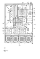
- FIG. 2 is a plan view of the electronic device 10.
- FIG. 3 is a cross-sectional view illustrating a partial configuration of the electronic device 10.
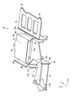
- FIG. 4 is a perspective view showing the configuration of the flow path guide unit 20
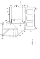
- FIG. 5 is a plan view showing the configuration of the flow path guide unit 20.
- arrows X, Y, and Z indicate three directions orthogonal to each other, where X is along the first direction, Y is along the second direction, and Z is along the third direction.
- the orientation with the bottom plate down is shown as an example with respect to directions such as up and down, left and right, front and back, but the orientation changes appropriately according to the orientation of the electronic device 10.
- the electronic device 10 includes a housing 11, a substrate unit 12 that is a cooling target unit, an HDD unit 13, an IC chip unit 15, a power supply unit 16, and a cooling unit 17. And a flow path guide unit 20.
- the housing 11 includes, for example, a rectangular bottom plate 11a, a front side plate 11b, a pair of left and right side plates 11c and 11d, a rear side plate 11e, and a top plate 11f arranged to face the bottom plate 11a.
- the housing 11 forms a rectangular parallelepiped accommodation space 11g surrounded by the bottom plate 11a, the top plate 11f, and the two sets of side plates 11b to 11e.
- the housing 11 accommodates various electronic components such as the HDD unit 13, the cooling unit 17, and the board unit 12 in the accommodating space 11g.
- the front side plate 11b includes a ventilation structure 31 that has a plurality of ventilation holes and is configured to allow intake, and is connected to a disk port for an optical drive disk, an insertion port for the HDD unit 13, and various cables such as a USB.
- a ventilation structure 31 that has a plurality of ventilation holes and is configured to allow intake, and is connected to a disk port for an optical drive disk, an insertion port for the HDD unit 13, and various cables such as a USB.
- Various terminals are provided.
- the rear side plate 11e includes a ventilation structure portion 31 having a plurality of ventilation holes and various terminals to which various cables such as a USB are connected.
- a plurality of HDD units 13 are arranged side by side in the X direction on one end side in the accommodation space 11g.
- a cooling unit 17 is provided adjacent to the rear of the HDD unit 13 in the accommodation space 11g. Further, the substrate unit 12 is disposed behind the cooling unit 17 in the accommodation space 11g.
- the HDD unit 13 includes a plurality of HDDs and an HDD housing that holds the HDDs.
- a cooling unit 17 is disposed behind the HDD unit 13, in other words, on the secondary side of the air flow path.
- a ventilation path is formed from the ventilation structure portion 31 of the front side plate 11b to the intake portion of the cooling unit 17.
- the upstream side in the blowing direction is referred to as a primary side
- the downstream side is referred to as a secondary side.
- the cooling unit 17 includes a fan holder 32 disposed on the bottom plate 11 a of the housing 11 and a plurality of fan units 34 a to 34 c supported by the fan holder 32. .
- three first fan units 34a, second fan units 34b, and third fan units 34c are arranged in parallel in the X direction.
- the fan holder 32 is a frame disposed on the bottom plate 11a of the housing 11, and has a plurality of fan accommodating portions that respectively hold the fan units 34a to 34c.
- the plurality of fan units 34 a to 34 c each include a fan case 35 having a blower opening 35 a and a blower fan 36 disposed in the fan case 35.
- the blower fan 36 is connected to the output shaft of the fan motor and is driven to rotate.
- the cooling unit 17 includes an intake port on the HDD unit 13 side, and includes a blower port 35a on the opposite side.
- the first fan unit 34 a and the second fan unit 34 b are disposed to face the substrate unit 12, and the third fan unit 34 c is disposed to face the IC chip unit 15.
- the substrate unit 12 is a bottom portion of the housing 11 and is disposed on the bottom plate 11 a, a first CPU unit 42 mounted on the substrate 41, and a second portion disposed on the secondary side of the first CPU unit 42. 2 CPU unit 43, and a RAID card unit 44 arranged behind the first CPU unit 42 and on the side of the second CPU unit 43.
- the board 41 and the first CPU unit 42 on the board 41 are the first cooling target part
- the second CPU unit 43 is the second cooling target part
- the RAID card unit 44 is the third cooling target part.
- the substrate 41 is a PCB substrate and is arranged in parallel with the bottom plate 11a along the XY plane.
- the first CPU unit 42 is disposed near the air outlet 35a of the second fan unit 34b.
- the first CPU unit 42 includes a first CPU 45 mounted on the substrate 41 and a first heat sink 47 mounted on the first CPU 45.
- the first heat sink 47 includes a plurality of radiating fins standing at a predetermined pitch Pt1.
- the second CPU unit 43 is arranged behind the right first fan unit 34a and behind the first CPU unit 42.
- the second CPU unit 43 includes a second CPU 46 mounted on the substrate 41 and a second heat sink 48 mounted on the second CPU 46.
- the second heat sink 48 includes a plurality of heat radiation fins erected at a predetermined pitch Pt2. The upper end of the second heat sink 48 is disposed at a predetermined position higher than the first heat sink 47.
- the RAID card unit 44 is arranged behind the first CPU unit 42.
- the RAID card unit 44 includes a plurality of RAID cards 44a that are erected on the substrate 41 and on which various electronic components are mounted.
- the upper end portion of the RAID card 44 a is, for example, higher than the upper end of the first heat sink 47 and has the same height as the upper end of the second heat sink 48.
- the flow path guide part 20 is molded from a transparent resin material having excellent heat resistance and workability.
- the flow path guide unit 20 is formed along the outer shape of the substrate unit 12 and integrally includes a plurality of wall-like members that cover the substrate unit 12 and divide the flow path into a plurality of parts.
- the flow path guide unit 20 is disposed on the substrate unit 12 to form a plurality of flow paths F1, F2, and F3 that pass backward from the cooling unit 17 through the substrate unit 12.
- the flow path guide unit 20 includes a first lid wall 21 that is a partition wall disposed on the first heat sink 47 on the secondary side of the second fan unit 34b, and a second heat sink from the secondary side of the first fan unit 34a.
- the duct part 22 which divides the 2nd flow path which reaches 48, and the power supply cover part 23 which covers a power supply unit are provided continuously and integrally.
- the first lid wall 21 is a plate-like member that extends across the height direction on the secondary side of the air blowing port 35a of the second fan unit 34b and divides the space vertically.
- the first lid wall 21 is disposed at a height near the center in the Z direction of the air blowing port 35a of the second fan unit 34b, and is disposed along the XY plane.
- the first lid wall 21 is disposed opposite to the upper end of the first heat sink 47 with a slight gap.
- a plurality of attachment pieces that are fastened to the housing 11 by fastening members are provided at the end of the first lid wall 21.
- the first lid wall 21 has a narrowed portion 21a slightly ahead of the center of the first CPU 45.
- the narrowed portion 21a is formed of a step which is continuous by a surface in which a part of the first lid wall 21 descends obliquely. That is, the first lid wall 21 is continuous by the narrowed portion 21a whose surfaces having different heights are inclined surfaces.
- the distance of the gap between the first heat sink 47 and the first lid wall 21 is reduced on the secondary side of the throttle portion 21a.
- a distance S1 between the first heat sink 47 and the first lid wall 21 is configured to be narrower than the pitch Pt1 of the heat sink fins of the heat sink at the rear portion of the throttle portion 21a.
- a first guide rib 21b and a second guide rib 21c are formed on the upper surface of the first lid wall 21 so as to stand upward.
- the first guide rib 21b and the second guide rib 21c are wall-shaped members having a predetermined thickness and extending obliquely so as to be displaced toward the center toward the rear.
- the first guide rib 21 b and the second guide rib 21 c are configured to have a height equivalent to that of the second lid wall 24.
- the first guide rib 21b and the second guide rib 21c are spaced apart from each other by a predetermined distance to form a first opening 21d through which cooling air can pass.
- a first flow path F1 extending from the cooling unit 17 to the first heat sink 47 is formed below the first lid wall 21.
- the duct portion 22 extends rearward from the vicinity of the air blowing port 35a of the first fan unit 34a by a predetermined width, and further displaces obliquely toward the rear and expands the width dimension. And cover the sides.
- the duct portion 22 includes a second lid wall 24 and a pair of guide side walls 25 and 26 disposed on both side edges of the second lid wall 24.
- the duct portion 22 forms a second flow path F2 extending from the vicinity of the air blowing port 35a of the first fan unit 34a to the second heat sink 48.
- the second lid wall 24 is disposed at the height of the first fan unit 34a at the tip of the air outlet 35a and above the air outlet 35a.
- the second lid wall 24 is a wall-like member that is arranged to intersect the height direction and divides the space vertically.
- the second lid wall 24 is disposed at a predetermined distance above the first lid wall 21 and extends in parallel with the bottom plate 11a along the XY plane.
- a throttle portion 24a is formed in a portion of the second lid wall 24 facing a predetermined position ahead of the center of the second CPU unit 43.
- the narrowed portion 24a is configured by a step that descends obliquely so that the position is lowered at a predetermined position of the second lid wall 24.
- a region behind the throttle portion 24 a of the second lid wall 24 is disposed opposite to the upper end of the second heat sink 48 with a slight gap.
- the distance S2 between the second heat sink 48 and the second lid wall 24 on the secondary side of the throttle portion 24a is set to be narrower than the pitch Pt2 of the radiating fins of the second heat sink 48.
- the guide side walls 25 and 26 are wall-like members extending along the ZY plane, and partition the space into a plurality in the X direction, which is the parallel direction of the blower fans.
- One guide side wall 25 (first side wall portion) extends downward from one side edge of the second lid wall 24.
- the guide side wall 25 is divided into two portions, and has a front side wall 25a and a rear side wall 25b.
- the front side wall 25 a of the guide side wall 25 reaches a part of the other side edge of the first lid wall 21 at the lower end. In other words, the front side wall 25 a of the guide side wall 25 stands from the side edge of the first lid wall 21.
- a second opening 25c having a predetermined width is formed between the front side wall 25a and the rear side wall 25b.
- the second flow path F2 in the duct part 22 communicates with the space on the first lid wall 21 through the second opening 25c.
- the other guide side wall 26 is formed over the entire length of the second lid wall 24.
- a second flow path F ⁇ b> 2 extending from the first fan unit 34 a to the second heat sink 48 is formed in a region surrounded by the guide side walls 25 and 26 below the duct portion 22.
- the rear part of the guide side wall 25 is erected from a rear side wall 25b which is an inner wall along the side wall of the second heat sink 48, a bottom wall part 25d having a predetermined width extending outside the rear side wall 25b, and the other end of the bottom wall part 25d.
- the outer wall portion 25e is provided integrally and formed in a double structure.
- the guide side wall 25 has a predetermined width. The guide side wall 25 narrows the gap between the second heat sink 48 and the RAID card unit 44, thereby suppressing the escape of wind into the gap and the air blowing direction so that the RAID card unit 44 is effectively cooled. To guide you.
- a third flow path F3 extending from the vicinity of the air blowing port 35a of the second fan unit 34b to the RAID card unit 44 through the first lid wall 21 is formed outside the guide side wall 25.
- the guide side wall 26 (second side wall portion) is opposed to the inner wall portion 26c along the side portion of the second heat sink 48, the bottom wall portion 26d having a predetermined width, and the inner wall portion 26c erected from the other end of the bottom wall portion 26d. And an outer wall portion 26e.
- the guide side wall 26 has a predetermined width that fills the gap between the second heat sink 48 and the power supply unit 16. The guide side wall 26 prevents the wind from escaping through the gap and guides the blowing direction so that the second heat sink 48 is effectively cooled.
- the upper end edge of the outer wall portion 26 e is continuous with the power source cover portion 23.
- the inner wall part 26c of the guide side wall 26 is displaced and inclined toward the center of the duct part 22 in the throttle part 24a. That is, in the throttle part 24a, the flow path of the duct part 22 is narrowed not only in the Z direction but also in the X direction by the inner wall part 26c, so that the flow velocity is increased.
- the power supply cover 23 is a plate-like member that is placed on the power supply unit 16 so as to face the power supply unit 16.
- a plurality of attachment pieces that are fastened to the housing 11 by fastening members are provided at the edge of the power supply cover portion 23.
- the flow path guide portion 20 configured as described above is placed over the substrate unit 12 and is fixed to the housing 11 by fastening members such as bolts at a plurality of mounting pieces 28 provided on the outer peripheral portion.
- each part of the flow path guide part 20 are determined based on the air distribution ratio according to the heat generation amount of the plurality of cooling target parts. That is, the air volume from the two fan units 34a and 34b is set so as to be guided to the three flow paths F1, F2, and F3 with a distribution corresponding to the heat generation amount of the units 42, 43, and 44.
- the heat generation amount of the first CPU unit 42 and the heat generation amount of the second CPU unit 43 are approximately the same, and the heat generation amount of the RAID card unit 44 is approximately 1/3 thereof.
- the air when the fan motor 55 is rotationally driven by the control unit, the air is sucked into the fan case from the air inlet through the air intake passage formed above and below the HDD unit 13, and from the air outlet 35a, The air is blown backward toward the substrate unit 12.
- the air sent from the air blowing port 35a is guided by the flow path guide unit 20 provided at the front of the air blowing port 35a. That is, the air from the two fan units 34a and 34b is vertically divided by the first lid wall 21 on one side and guided to the duct portion 22 on the other side.
- the air guided onto the first lid wall 21 is further guided by the first guide rib 21b and the second guide rib 21c, partly guided from the first opening 21d to the third flow path F3, and partly second. Guided into the duct portion 22 from the opening 25c.
- the air guided to the first flow path F1 cools the first CPU unit 42.
- the air guided to the second flow path F2 cools the second CPU unit 43.
- the air guided to the third flow path F3 cools the RAID card unit 44.
- the flow rate from the cooling unit 17 is reduced by providing the flow path guide portion 20 that covers the substrate unit 12 and divides the flow path into a plurality of cooling targets. Can be distributed properly and effective cooling can be realized.
- the duct portion 22 and the first lid wall 21 can effectively guide the heat sinks at different positions by dividing the air volume vertically and horizontally.
- a desired air volume can be distributed also to the secondary-side second heat sink 48. That is, for example, in an arrangement in which a plurality of heat sinks of the same height are generally arranged at the front and back, the air heated by the first heat sink 47 on the primary side is supplied to the secondary heat sink, so that the cooling efficiency is lowered.
- cold air can be reliably supplied to the second heat sink 48 on the secondary side.
- the plurality of fan units 34a and 34b are arranged in parallel.
- the first flow path F1 and the second flow path F2 are configured to communicate with both the fan units 34a and 34b, respectively.
- the fan units 34a and 34b fail, the cooling air of the remaining fan units 34a and 34b can be distributed, and the cooling performance can be maintained.
- the guide side walls 25 and 26 have a double structure to eliminate a dead space, and the shape of the flow path guide portion 20 is made to conform to the outer shape of the substrate unit 12 so that the cooling air escapes. This can be suppressed and cooling air can be used efficiently.
- the flow path guide portion 20 by configuring the flow path guide portion 20 from a transparent resin, it is possible to check the wiring status even when the flow path guide portion 20 is attached. Further, since the plurality of wall-like members provided in the flow path guide portion 20 can define the positions of various cables in addition to the sections of the flow paths, the workability of the wiring work can be improved.
- the present invention is not limited to the above embodiment.
- the flow path guide portion 20 is made of a transparent resin material, but is not limited thereto, and may be made of other materials such as metal.
- the flow path guide unit 20 is configured in the above-described shape in accordance with the shape of the substrate unit 12 and the amount of heat generated in each unit, but is not limited thereto.
- the position and shape of the wall-shaped member can be changed as appropriate according to the positional relationship and number of the units 42, 43, and 44.
- the number of flow paths can be increased or decreased according to the position and number of cooling target portions.
Landscapes
- Engineering & Computer Science (AREA)
- Microelectronics & Electronic Packaging (AREA)
- Physics & Mathematics (AREA)
- Thermal Sciences (AREA)
- Cooling Or The Like Of Electrical Apparatus (AREA)
- Cooling Or The Like Of Semiconductors Or Solid State Devices (AREA)
Abstract
Description
筐体11は、例えば、長方形状の底板11aと、前方の側板11bと、左右一対の側板11c,11dと、後方の側板11eと、底板11aに対向配置される天板11fと、を備える。筐体11は、これらの底板11a、天板11f、及び2組の側板11b~11eによって囲まれる直方体状の収容空間11gを形成する。筐体11は、収容空間11g内に、HDDユニット13、冷却ユニット17、基板ユニット12等の、各種の電子部品を収容する。
Claims (7)
- 筐体内に配され、第1冷却対象部と、第2冷却対象部と、を備える冷却対象ユニットと、
前記冷却対象ユニット上に配され、前記筐体内の空間を複数に仕切る壁状部材を有し、前記第1冷却対象部を通る第1流路と、前記第2冷却対象部を通る第2流路と、を形成する、流路ガイド部と、
を備える、電子機器。 - 送風装置を備え、
前記第1冷却対象部は、前記送風装置の送風方向下流側に配され、
前記第2冷却対象部は、前記第1冷却対象部よりも前記送風方向下流側に配され、
前記第1冷却対象部と前記第2冷却対象部とは、前記送風装置に対して前記送風方向上流に向けて投影した場合に重なる位置に配され、
前記流路ガイド部は、前記送風装置の送風方向下流側の空間を、前記送風方向と交差する第1方向に複数に分割する第1側壁部と、前記第1側壁部の第1方向一方側に延び前記第1冷却対象部上を覆う第1蓋壁と、前記第1側壁部の第1方向他方側に延びる第2蓋壁と、を有し、
前記第1側壁部及び前記第2蓋壁は、前記第1冷却対象部よりも前記送風方向下流側に延び、送風方向下流側の部位において前記第2蓋壁が前記第2冷却対象部上を覆うとともに前記第1側壁部が前記第2冷却対象部の第1方向一方側の側方を覆う、請求項1記載の電子機器。 - 前記送風装置は、複数の送風ファンを前記第1方向に並列して備え、
前記冷却対象ユニットは、前記筐体内の底部に配される基板を備える基板ユニットであり、
前記第1冷却対象部は、前記基板上に配される第1CPUと、第1CPU上に配される第1の放熱フィンと、を備える第1のCPUユニットであり、
前記第2冷却対象部は、前記基板の前記第1CPUよりも送風方向下流側に配される第2CPUと、前記第2CPU上に配されるとともに前記第1の放熱フィンよりも高さが高い第2の放熱フィンと、を備える第2のCPUユニットであり、
前記第2蓋壁は、前記第1蓋壁より高い位置に配され、
前記第1蓋壁下に、前記第1冷却対象部に至る前記第1流路が形成され、
前記第1側壁部は、前記第2蓋壁の前記第1方向一方の側縁から下方に延び、前記第1蓋壁の第1方向他方側の側縁に接続され、
前記第2蓋壁の第1方向他方側の側縁から下方に延びる第2側壁部が設けられ、
前記第2蓋壁と前記第1側壁部と前記第2側壁部とで構成されるダクト部により、前記第1流路の第1方向他方側から、送風方向下流側に延びて前記第2冷却対象部に至る、前記第2流路が形成される、請求項2に記載の電子機器。 - 前記第1蓋壁または前記第2蓋壁は、前記第1冷却対象部または前記第2冷却対象部の中心よりも送風方向上流側に、前記第1流路または前記第2流路が縮小するように下方に変位する絞り部を備える、請求項2または請求項3に記載の電子機器。
- 前記第1蓋壁及び前記第1冷却対象部より前記送風方向下流側に配される第3冷却対象部を備え、
前記第1蓋壁は、空間を高さ方向に分割し、
前記第1側壁部の前記第1方向一方側に、前記第1蓋壁の上側を通って第3冷却対象部に至る第3流路が形成される、請求項2乃至4のいずれかに記載の電子機器。 - 前記第1側壁部は、前側壁と後側壁とを有するとともに、前記第1蓋壁上の空間と前記第2流路との間に配され、前記前側壁と前記後側壁との間に、前記第1蓋壁上の空間と前記第2蓋壁下の前記第2流路とを連通する開口を有し、
前記第1蓋壁の上面には、上方に延びる壁状部材であって、送風方向下流側が前記第2流路側に延び、前記第1側壁部の前記開口に向かう、ガイドリブが設けられる、請求項3乃至請求項5のいずれかに記載の電子機器。 - 前記流路ガイドは、透明な材料で構成される複数の壁状部材を一体に有するとともに、
前記冷却対象部上から被せられた状態で前記筐体に締結される取付け部を、一体に備える、請求項1乃至6のいずれかに記載の電子機器。
Priority Applications (4)
| Application Number | Priority Date | Filing Date | Title |
|---|---|---|---|
| KR1020187036199A KR102149444B1 (ko) | 2016-11-04 | 2017-10-23 | 전자 기기 |
| JP2018548946A JP6730444B2 (ja) | 2016-11-04 | 2017-10-23 | 電子機器 |
| CN201780038298.7A CN109328487B (zh) | 2016-11-04 | 2017-10-23 | 电子设备 |
| SG11201902293WA SG11201902293WA (en) | 2016-11-04 | 2017-10-23 | Electronic apparatus |
Applications Claiming Priority (2)
| Application Number | Priority Date | Filing Date | Title |
|---|---|---|---|
| JP2016-216464 | 2016-11-04 | ||
| JP2016216464 | 2016-11-04 |
Publications (1)
| Publication Number | Publication Date |
|---|---|
| WO2018084016A1 true WO2018084016A1 (ja) | 2018-05-11 |
Family
ID=62075793
Family Applications (1)
| Application Number | Title | Priority Date | Filing Date |
|---|---|---|---|
| PCT/JP2017/038206 Ceased WO2018084016A1 (ja) | 2016-11-04 | 2017-10-23 | 電子機器 |
Country Status (6)
| Country | Link |
|---|---|
| JP (1) | JP6730444B2 (ja) |
| KR (1) | KR102149444B1 (ja) |
| CN (1) | CN109328487B (ja) |
| SG (1) | SG11201902293WA (ja) |
| TW (1) | TWI669049B (ja) |
| WO (1) | WO2018084016A1 (ja) |
Cited By (3)
| Publication number | Priority date | Publication date | Assignee | Title |
|---|---|---|---|---|
| US20220354355A1 (en) * | 2020-01-29 | 2022-11-10 | Olympus Corporation | Cooling device of endoscope |
| JP2023028305A (ja) * | 2021-08-19 | 2023-03-03 | 日本電産サンキョー株式会社 | コントローラ |
| EP4654766A1 (en) * | 2024-05-24 | 2025-11-26 | RNV Holding B.V. | Cooling fluid deflector |
Families Citing this family (2)
| Publication number | Priority date | Publication date | Assignee | Title |
|---|---|---|---|---|
| EP4223177B1 (en) | 2019-07-07 | 2025-12-31 | Shenzhen Ulike Smart Electronics Co., Ltd. | PORTABLE HAIR REMOVAL DEVICE |
| CN121218493A (zh) * | 2024-06-25 | 2025-12-26 | 富联精密电子(天津)有限公司 | 收容装置和机柜 |
Citations (4)
| Publication number | Priority date | Publication date | Assignee | Title |
|---|---|---|---|---|
| JP2008147299A (ja) * | 2006-12-07 | 2008-06-26 | Toshiba Corp | 電子機器内の発熱体の冷却構造 |
| JP2009200144A (ja) * | 2008-02-20 | 2009-09-03 | Mitsubishi Electric Corp | 冷却装置 |
| US20120289142A1 (en) * | 2011-05-10 | 2012-11-15 | Hon Hai Precision Industry Co., Ltd. | Heat dissipation assembly for electronic device |
| JP2013016569A (ja) * | 2011-07-01 | 2013-01-24 | Nippon Telegr & Teleph Corp <Ntt> | 冷却機構体 |
Family Cites Families (11)
| Publication number | Priority date | Publication date | Assignee | Title |
|---|---|---|---|---|
| JP3254756B2 (ja) | 1992-10-13 | 2002-02-12 | 株式会社日立製作所 | 電子装置 |
| US6643131B1 (en) * | 2002-10-10 | 2003-11-04 | First International Computer, Inc. | Wind guide device for CPU cooler |
| CN100543639C (zh) * | 2005-11-01 | 2009-09-23 | 鸿富锦精密工业(深圳)有限公司 | 散热系统 |
| DE102005063024B4 (de) * | 2005-12-30 | 2007-10-25 | Fujitsu Siemens Computers Gmbh | Luftleithaube |
| US7768781B2 (en) * | 2007-12-18 | 2010-08-03 | Lenovo Singapore Pte. Ltd | Computer with improved cooling features |
| CN101644946B (zh) * | 2008-08-08 | 2012-10-31 | 英业达股份有限公司 | 导风罩 |
| JP2010198185A (ja) | 2009-02-24 | 2010-09-09 | Nec System Technologies Ltd | 冷却システム、コンピュータ装置、冷却ファン制御装置、冷却ファン制御方法、及び冷却ファン制御プログラム |
| CN101959390B (zh) * | 2009-07-20 | 2014-12-03 | 南通奥普机械工程有限公司 | 组合式导风罩 |
| US8369083B2 (en) * | 2010-02-16 | 2013-02-05 | Manufacturing Resources International, Inc. | System and method for selectively engaging cooling fans within an electronic display |
| JP5702962B2 (ja) * | 2010-07-20 | 2015-04-15 | 株式会社東芝 | 電子機器の放熱構造 |
| JP5920074B2 (ja) * | 2012-07-12 | 2016-05-18 | 富士通株式会社 | 電子機器及び発熱部品の冷却方法 |
-
2017
- 2017-10-23 KR KR1020187036199A patent/KR102149444B1/ko active Active
- 2017-10-23 CN CN201780038298.7A patent/CN109328487B/zh active Active
- 2017-10-23 SG SG11201902293WA patent/SG11201902293WA/en unknown
- 2017-10-23 WO PCT/JP2017/038206 patent/WO2018084016A1/ja not_active Ceased
- 2017-10-23 JP JP2018548946A patent/JP6730444B2/ja active Active
- 2017-10-24 TW TW106136461A patent/TWI669049B/zh active
Patent Citations (4)
| Publication number | Priority date | Publication date | Assignee | Title |
|---|---|---|---|---|
| JP2008147299A (ja) * | 2006-12-07 | 2008-06-26 | Toshiba Corp | 電子機器内の発熱体の冷却構造 |
| JP2009200144A (ja) * | 2008-02-20 | 2009-09-03 | Mitsubishi Electric Corp | 冷却装置 |
| US20120289142A1 (en) * | 2011-05-10 | 2012-11-15 | Hon Hai Precision Industry Co., Ltd. | Heat dissipation assembly for electronic device |
| JP2013016569A (ja) * | 2011-07-01 | 2013-01-24 | Nippon Telegr & Teleph Corp <Ntt> | 冷却機構体 |
Cited By (6)
| Publication number | Priority date | Publication date | Assignee | Title |
|---|---|---|---|---|
| US20220354355A1 (en) * | 2020-01-29 | 2022-11-10 | Olympus Corporation | Cooling device of endoscope |
| US12256516B2 (en) * | 2020-01-29 | 2025-03-18 | Olympus Corporation | Cooling device of endoscope |
| JP2023028305A (ja) * | 2021-08-19 | 2023-03-03 | 日本電産サンキョー株式会社 | コントローラ |
| JP7734019B2 (ja) | 2021-08-19 | 2025-09-04 | ニデックインスツルメンツ株式会社 | コントローラ |
| EP4654766A1 (en) * | 2024-05-24 | 2025-11-26 | RNV Holding B.V. | Cooling fluid deflector |
| WO2025242888A1 (en) | 2024-05-24 | 2025-11-27 | Rnv Holding B.V. | Cooling fluid deflector |
Also Published As
| Publication number | Publication date |
|---|---|
| TWI669049B (zh) | 2019-08-11 |
| TW201831072A (zh) | 2018-08-16 |
| CN109328487B (zh) | 2020-06-05 |
| JPWO2018084016A1 (ja) | 2019-09-19 |
| SG11201902293WA (en) | 2019-05-30 |
| CN109328487A (zh) | 2019-02-12 |
| JP6730444B2 (ja) | 2020-07-29 |
| KR102149444B1 (ko) | 2020-08-28 |
| KR20190008328A (ko) | 2019-01-23 |
Similar Documents
| Publication | Publication Date | Title |
|---|---|---|
| JP6730444B2 (ja) | 電子機器 | |
| US8228671B2 (en) | Electronic apparatus including a cooling unit and a wall member | |
| CN105159018B (zh) | 投影装置 | |
| US11259440B1 (en) | Computer case | |
| CN102262426A (zh) | 散热装置 | |
| CN104105382A (zh) | 散热片和包括该散热片的电力转换装置 | |
| TW201630520A (zh) | 散熱裝置 | |
| CN102915096A (zh) | 电子装置 | |
| JP6219174B2 (ja) | 電気機器 | |
| JP2020180709A (ja) | 空気調和機の室外機 | |
| JP6942267B2 (ja) | 室外機 | |
| TW201328553A (zh) | 電子裝置散熱系統 | |
| JP2013074083A (ja) | シールドボックスとそれを有する画像形成装置 | |
| JP6615630B2 (ja) | 電気機器 | |
| JP2022075116A (ja) | 電子機器 | |
| CN109845425B (zh) | 电子设备 | |
| CN102592686B (zh) | 热交换机 | |
| JP2019054055A (ja) | ファンユニット及び電子機器 | |
| US20050189088A1 (en) | Circulation structure of heat dissipation device | |
| CN213841139U (zh) | 制冷循环装置的室外机 | |
| TWI812193B (zh) | 桌上型電腦 | |
| TW202211776A (zh) | 電子裝置 | |
| JP2005333113A (ja) | 放熱装置 | |
| TWI511656B (zh) | 伺服模組 | |
| CN114189976A (zh) | 电子装置 |
Legal Events
| Date | Code | Title | Description |
|---|---|---|---|
| 121 | Ep: the epo has been informed by wipo that ep was designated in this application |
Ref document number: 17867537 Country of ref document: EP Kind code of ref document: A1 |
|
| ENP | Entry into the national phase |
Ref document number: 20187036199 Country of ref document: KR Kind code of ref document: A |
|
| ENP | Entry into the national phase |
Ref document number: 2018548946 Country of ref document: JP Kind code of ref document: A |
|
| NENP | Non-entry into the national phase |
Ref country code: DE |
|
| 122 | Ep: pct application non-entry in european phase |
Ref document number: 17867537 Country of ref document: EP Kind code of ref document: A1 |