WO2018084015A1 - ゴム状重合体用押出乾燥機、ゴム状重合体の乾燥方法、およびゴム状重合体の製造方法 - Google Patents
ゴム状重合体用押出乾燥機、ゴム状重合体の乾燥方法、およびゴム状重合体の製造方法 Download PDFInfo
- Publication number
- WO2018084015A1 WO2018084015A1 PCT/JP2017/038199 JP2017038199W WO2018084015A1 WO 2018084015 A1 WO2018084015 A1 WO 2018084015A1 JP 2017038199 W JP2017038199 W JP 2017038199W WO 2018084015 A1 WO2018084015 A1 WO 2018084015A1
- Authority
- WO
- WIPO (PCT)
- Prior art keywords
- polymer
- rubber
- shaft
- outer diameter
- screw
- Prior art date
- Legal status (The legal status is an assumption and is not a legal conclusion. Google has not performed a legal analysis and makes no representation as to the accuracy of the status listed.)
- Ceased
Links
Images

Classifications
-
- C—CHEMISTRY; METALLURGY
- C08—ORGANIC MACROMOLECULAR COMPOUNDS; THEIR PREPARATION OR CHEMICAL WORKING-UP; COMPOSITIONS BASED THEREON
- C08C—TREATMENT OR CHEMICAL MODIFICATION OF RUBBERS
- C08C4/00—Treatment of rubber before vulcanisation, not provided for in groups C08C1/00 - C08C3/02
-
- B—PERFORMING OPERATIONS; TRANSPORTING
- B29—WORKING OF PLASTICS; WORKING OF SUBSTANCES IN A PLASTIC STATE IN GENERAL
- B29B—PREPARATION OR PRETREATMENT OF THE MATERIAL TO BE SHAPED; MAKING GRANULES OR PREFORMS; RECOVERY OF PLASTICS OR OTHER CONSTITUENTS OF WASTE MATERIAL CONTAINING PLASTICS
- B29B13/00—Conditioning or physical treatment of the material to be shaped
- B29B13/02—Conditioning or physical treatment of the material to be shaped by heating
-
- B—PERFORMING OPERATIONS; TRANSPORTING
- B29—WORKING OF PLASTICS; WORKING OF SUBSTANCES IN A PLASTIC STATE IN GENERAL
- B29B—PREPARATION OR PRETREATMENT OF THE MATERIAL TO BE SHAPED; MAKING GRANULES OR PREFORMS; RECOVERY OF PLASTICS OR OTHER CONSTITUENTS OF WASTE MATERIAL CONTAINING PLASTICS
- B29B13/00—Conditioning or physical treatment of the material to be shaped
- B29B13/06—Conditioning or physical treatment of the material to be shaped by drying
-
- B—PERFORMING OPERATIONS; TRANSPORTING
- B29—WORKING OF PLASTICS; WORKING OF SUBSTANCES IN A PLASTIC STATE IN GENERAL
- B29B—PREPARATION OR PRETREATMENT OF THE MATERIAL TO BE SHAPED; MAKING GRANULES OR PREFORMS; RECOVERY OF PLASTICS OR OTHER CONSTITUENTS OF WASTE MATERIAL CONTAINING PLASTICS
- B29B13/00—Conditioning or physical treatment of the material to be shaped
- B29B13/06—Conditioning or physical treatment of the material to be shaped by drying
- B29B13/065—Conditioning or physical treatment of the material to be shaped by drying of powder or pellets
-
- C—CHEMISTRY; METALLURGY
- C08—ORGANIC MACROMOLECULAR COMPOUNDS; THEIR PREPARATION OR CHEMICAL WORKING-UP; COMPOSITIONS BASED THEREON
- C08F—MACROMOLECULAR COMPOUNDS OBTAINED BY REACTIONS ONLY INVOLVING CARBON-TO-CARBON UNSATURATED BONDS
- C08F6/00—Post-polymerisation treatments
- C08F6/26—Treatment of polymers prepared in bulk also solid polymers or polymer melts
-
- B—PERFORMING OPERATIONS; TRANSPORTING
- B29—WORKING OF PLASTICS; WORKING OF SUBSTANCES IN A PLASTIC STATE IN GENERAL
- B29K—INDEXING SCHEME ASSOCIATED WITH SUBCLASSES B29B, B29C OR B29D, RELATING TO MOULDING MATERIALS OR TO MATERIALS FOR MOULDS, REINFORCEMENTS, FILLERS OR PREFORMED PARTS, e.g. INSERTS
- B29K2009/00—Use of rubber derived from conjugated dienes, as moulding material
Definitions
- the present invention relates to a rubber-like polymer extrusion dryer, a method for drying a rubber-like polymer, and a method for producing a rubber-like polymer.
- This extrusion dryer includes a cylinder having a hopper into which a rubber-like polymer is charged at one end and a die at the other end, and a screw rotatably disposed in the cylinder.
- the charged rubber-like polymer is conveyed to the die while being subjected to high temperature and high pressure by compression, shearing action or the like in the extrusion dryer, and is pushed out into the atmosphere from the nozzle of the die.
- the water contained in the rubber-like polymer is rapidly vaporized and released into the atmosphere, the water content of the rubber-like polymer can be reduced at a stretch.
- the temperature and pressure of the rubber-like polymer immediately before being extruded from the die nozzle are important factors for determining the quality of the rubber-like polymer to be extruded.
- unnecessary heat is generated in the cylinder, and the rubber-like polymer is deteriorated by the heat, and in some cases, gelation may occur.
- drying may be insufficient under operating conditions that take into account the deterioration of the rubbery polymer due to unnecessary heat.
- a rubbery polymer that is prevented from gelling by suppressing unnecessary heat generation that may occur during operation and sufficiently dried is obtained. It is an object of the present invention to provide an extrusion dryer for a rubbery polymer that can be obtained.
- one aspect of the present invention includes a cylinder having a hopper into which a rubber-like polymer is charged at one end and a die at the other end, a shaft rotatably disposed in the cylinder, and a shaft. And a screw having a spiral flight formed on the outer peripheral surface of the shaft, and a rubber-like polymer extrusion dryer, wherein the screw includes a plurality of zones each having a transport unit and a compression unit, In the zone closest to the die, the outer diameter of the shaft in the transport section is smaller than the outer diameter of the shaft in the compression section.
- an extrusion dryer for a rubbery polymer is provided.
- FIG. 1 shows a schematic structure of an extrusion dryer according to an embodiment of the present invention.
- FIG. 1 shows a partial cutaway view of an expansion-type extrusion dryer 10 as an example.
- the extrusion dryer 10 has a hopper 1 into which a rubbery polymer (material or material to be dried) containing moisture is charged at one end and a cylindrical shape having a die 3 at the other end.
- a cylinder 2 and a screw (worm) 6 disposed in the cylinder 2 are provided.
- the rubber-like polymer supplied from the hopper 1 is conveyed toward the die 3 in the cylinder 2 by the rotation of the screw 6 shown in FIG.
- the rubber-like polymer is heated and heated by being sheared and compressed between the liner in the cylinder 2 and the flight 62 of the screw 6 and between the breaker bolt 7 and the flight 62 of the screw 6. Pressed. Heating may be performed by heating means provided on the cylinder 2 and / or the shaft 61 of the screw 6.
- the hydrous rubber polymer to which high temperature and high pressure are applied in the cylinder 2 is transported to the die 3 and ejected from the nozzle of the die 3 into the atmosphere. At this time, drying (expansion drying) is performed by evaporating high-temperature, high-pressure moisture and the like contained in the rubber-like polymer all at once and releasing them into the atmosphere.
- the screw 6 is driven by the driving device 4 and is configured and arranged to be rotatable with a predetermined gap from the inner surface of the cylinder 2.
- the inner diameter of the cylinder 2 is substantially the same except for the vicinity of the die 3.
- the screw 6 has a hollow shaft 61 and a spiral flight (blade) 62 formed so as to protrude from the outer peripheral surface of the shaft 61. Since the flight 62 has a notch, the spiral shape of the flight 62 is discontinuous and contacts the breaker bolt 7 that is implanted so as to protrude radially inward from the side surface of the cylinder 2. It is supposed not to. When the breaker bolt 7 is not provided, the spiral shape of the flight 62 can be formed continuously.
- the second zone 22 has two zones, a first zone 21 and a second zone 22.
- the first zone 21 includes a transport unit 21A and a compression unit 21B adjacent to the transport unit 21A on the hopper 1 side.
- the second zone 22 closest to the die 3 includes the transport unit 22A and the transport unit. It consists of a compression part 22B adjacent to 22A on the hopper 1 side.
- a section adjacent to the hopper 1 side of the first zone 21 is a hopper portion 25.
- the screw 6 has a plurality of zones 21 and 22 each including a conveying unit and a compressing unit, so that the temperature and pressure are increased stepwise, and the locations where the temperature and pressure are high are dispersed. Therefore, the load fluctuation of the compression unit and the conveyance unit adjacent to the die can be reduced.
- a rubber-like polymer containing a large amount of water shows properties as a solid, but it tends to generate heat locally because of the low uniformity of the material.
- rubber-like polymers containing a lot of water have low thermal conductivity, resulting in temperature distribution and pressure distribution, unstable conveyance, surging (a phenomenon in which an extrusion dryer stalls due to backflow, etc., and does not function), etc. It is easy to cause. For this reason, by applying temperature and pressure in the first zone and increasing the uniformity, and further increasing the uniformity in the second zone, the uniformity of the transport amount, temperature distribution, and pressure distribution can be increased in stages, It can be expanded in a uniform state.
- This repetition by providing a plurality of zones may be two or more, and may have three or more configurations depending on the properties of the material to be dried.
- the outer diameter of the shaft 61 in the conveying portion 22A is smaller than the outer diameter d 2B of the shaft 61 in the compression unit 22B Yes.
- the outer diameter D of the screw 6 (the outer diameter of the flight 62) D is constant, the outer diameter of the shaft 61 in the second zone 22 has the above relationship, so that the second conveyance is performed.
- the height h 2A of the flight 62 in the part 22A can be made larger than the height h 2B of the flight 62 in the second compression part 22B.
- the flight height h of the screw 6 corresponds to the outer radius of the screw 6 (the outer radius of the flight 62) D / 2 minus the outer radius d / 2 of the shaft 61.
- the amount of heat generated in the transfer of the rubber-like polymer in the cylinder 2 is proportional to the square of the shear rate.
- the shear rate is proportional to the speed in the direction in which the rubber-like polymer is subjected to shear stress, that is, the rotational speed, and inversely proportional to the flight height h. Therefore, if the flight height h is increased, the shear rate is reduced and the amount of heat generated is also reduced.
- the shaft outer diameter d 2B of the shaft outside diameter d 2A the second compression portion 22B of the second conveying portion 22A as described above, reducing the generation amount of heat (inevitably amount of heat generated) Can do. As a result, excessive temperature rise of the rubber-like polymer can be prevented, and alteration (gelation) can be suppressed.
- the shaft outer diameter d 2A of the transport section 22A smaller than the shaft outer diameter d 2B of the compression section 22B in the second zone 22, the volume inside the transport section 22A of the second zone 22 (accommodated in the transport section 22A).
- the volume of the material that can be made) increases, and the transport volume V 2A also increases.
- the conveying volume V 2A of the conveyor section 22A in the second zone 22 the ratio of the values for the transport volume V 2B compression section 22B (conveying volume or compression ratio (V 2A / V 2B)) be increased it can. That is, the compression degree of the rubber-like polymer in the compression part 22B can be increased.
- a rubbery polymer having a water content (water content) of about 40% by mass can be extruded and dried to a water content of 10% by mass or less.
- the temperature and pressure of the rubber-like polymer at the position immediately before extrusion which is particularly important in production (or The outlet temperature and outlet pressure) can be well controlled.
- the rotational speed N of the screw 6 can be increased as compared with the conventional configuration. Thereby, the recovery amount of the dry rubber-like polymer per unit time can be increased, and the productivity can be improved.
- the pitch of the flight 62 of the screw 6 in the second zone 22 is substantially constant as shown in FIG. That is, in the second zone 22, not by making the pitch of the flight 62 different between the second conveyance unit 22 ⁇ / b> A and the second compression unit 22 ⁇ / b> B, but by making the outer diameter d of the shaft 61 different, the conveyance volume ratio (V 2A / V2B ) is increased.
- the shaft outer diameter d 2A of the second conveying portion 22A is made smaller than the shaft outer diameter d 2B of the second compression unit 22B, if the generation of unwanted heat is suppressed, and a second conveying portion 22A
- the pitch of the flights 62 may be different between the second compression unit 22B.
- Shaft outer diameter d 2A of the second conveying portion 22A in the second zone 22 is preferably constant across over the end from the end of the hopper 1 side of the die 3 side of the conveying portion 22A, the design, Fig. As shown in FIG. 2, the shaft 61 may be tapered at both ends of the transport portion 22A. In that case, between the end of the hopper 1 side and the die 3 side end, the shaft outer diameter of the central portion which is substantially constant, may be a shaft outer diameter d 2A.
- the transport volume in the second transport section 22A in the second zone 22, the central portion where the outer diameter of the shaft is substantially constant between the end of the screw 61 on the hopper 1 side and the end of the die 3 side.
- the transport volume in may be the transport volume V 2A .
- the ratio of the shaft outer diameter d 2B of the compression section 22B and the shaft outer diameter d 2A of the transport section 22A in the second zone 22 is preferably 1: 0.8 to 1: 0.98. More preferably, it is 1: 0.85 to 1: 0.96. 1: 0.98 or less increases the conveyance volume ratio (V 2A / V 2B ) in the second zone 22 while suppressing unnecessary heat generation in the dryer and avoiding excessive temperature rise.
- the effect of ensuring the pressure for drying can be enhanced. Therefore, higher drying efficiency can be obtained while preventing deterioration (gelation) of the rubber-like polymer.
- strength of the shaft 61 sufficient for extrusion operation of a rubber-like polymer is securable by setting it as 1: 0.8 or more.
- the width (thickness) w 2A flight 61 of the second conveying portion 22A is smaller than the width w 2B flight 61 of the second compression portion 22B.
- the flight width w 2A of the second transport unit 22A is made smaller than the width w 2B of the flight 61 of the second compression unit 22B, from the viewpoint of increasing the transport volume ratio (V 2A / V 2B ) only, it is not necessary to reduce the shaft outer diameter d 2A of the conveyor section 22A. That is, the conveyance volume ratio (V 2A / V 2B ) can be increased while maintaining the strength of the shaft 61 of the screw 6.
- the ratio of the flight width w 2B of the second compression unit 22B and the flight width w 2A of the second transport unit 22A depends on the sizes of the extrusion dryer 10 and the screw 6, but is 1: 0.4 to 1: 0.8 is preferable, and 1: 0.45 to 1: 0.6 is more preferable. By setting it as 1: 0.8 or less, a conveyance volume ratio can be enlarged and the pressure of the rubber-like polymer just before extrusion can be raised. Moreover, the intensity
- the ratio with the volume V 2A of the rubber-like polymer conveyed when one rotation is more than 1: 1.
- it is preferably 1: 1.1 to 1: 5, more preferably 1: 1.5 to 1: 2.5, and more preferably 1: 1.6 to 1: 2.2. 1: 1.8 to 1: 2.0 is more preferable.
- the pressure of the rubber-like polymer just before extrusion can be made high.
- the water content of the extruded rubbery polymer can be promoted to evaporate in the air, and a high-quality rubbery polymer having a low moisture content can be obtained.
- the mechanical strength of an extrusion dryer can be maintained by setting it as 1: 5 or less.
- the first zone 21 has a configuration different from that of the second zone 22. That is, the shaft outer diameter of the first transport unit 21A in the first zone 21 is the same as the shaft outer diameter of the first compression unit 21B. Further, the pitch of the flights 62 of the first transport unit 21A is larger than the pitch of the flights 62 of the first compression unit 21B, and the widths of the flights 62 are equal between the first transport unit 21A and the first compression unit 21B. In the first zone 21 according to the illustrated example, the conveyance volume ratio is made larger than 1 by making the pitch of the flights 62 different between the conveyance unit and the compression unit.
- the first zone 21 may have a configuration other than the above, or may have the same configuration as the second zone 22.
- the shaft outer diameter in the first transport unit 21A can be made smaller than the shaft outer diameter in the first compression unit 21B.
- the same effect as that obtained in the second zone 22, that is, the effect that the drying of the rubber-like polymer can be sufficiently promoted while suppressing unnecessary heat generation can be obtained also in the first zone 21. Further, a high quality rubbery polymer can be obtained.
- the ratio of the shaft outer diameter of the compression unit 21B to the shaft outer diameter of the transport unit 21A is 1: 0.8 to 1: 0.98.
- 1: 0.85 to 1: 0.96 is more preferable.
- the volume of the rubber-like polymer conveyed when the screw rotates once in the compression section 21A and the volume of the rubber-like polymer conveyed when the screw rotates once in the conveyance section 21B can be greater than 1: 1.
- the ratio is preferably 1: 1.5 to 1: 2.5, more preferably 1: 1.6 to 1: 2.2, and 1: 1.8 to 1: 2.0. It is more preferable.
- the flight width of the first transport unit 21A may be smaller than the flight width of the first compression unit 21B.
- the ratio is preferably 1: 0.4 to 1: 0.8, more preferably 1: 0.45 to 1: 0.6.
- the extrusion dryer 10 may have three or more such zones.
- unnecessary heat generation is suppressed by making the outer diameter of the shaft 61 in the transport section 21A smaller than the outer diameter of the shaft 61 in the compression section 21B. be able to.
- the conveyance volume ratio can be increased in each of the plurality of first zones 21, the pressure immediately before the rubber-like polymer is extruded can be maintained sufficiently high.
- the cylinder 2 has an inner diameter and an outer diameter
- the screw 6 has an outer diameter that is constant in the axial direction.
- these diameters are not necessarily constant. Even if one or more of the diameter is varied in the axial direction, the shaft outer diameter d 2A of the second conveying portion 22A smaller than the shaft outer diameter d 2B of the second compression unit 22B, or the By making the flight height h 2A of the second transport unit 22A larger than the flight height h 2B of the second compression unit 22B, it is possible to perform drying well while suppressing excessive heat generation in the extrusion dryer 10. The effect of this invention of this application can be acquired.
- the type of rubber-like polymer extruded and dried according to this embodiment is not particularly limited.
- a method for drying a rubber-like polymer in which the rubber-like polymer is dried using the above-described extrusion dryer 10. Moreover, in this embodiment, the manufacturing method of the rubber-like polymer using the above-mentioned extrusion dryer 10 is also provided.
- FIG. 3 is a flowchart showing an example of a method for producing a rubbery polymer according to an embodiment of the present invention.
- the method for producing the rubber-like polymer of this example includes a polymerization step S1, a coagulation step S2, a dehydration step S3, an extrusion drying step S4, a vibration drying step S5, and a molding step S6.
- a rubber raw material such as butadiene is polymerized by a polymerization reaction such as emulsion polymerization or solution polymerization to obtain a latex of a rubber-like polymer, a polymer solution, or the like.
- a rubber-like polymer slurry is prepared by removing the solvent or latex of the rubber-like polymer by a steam stripping method or by salt coagulation.
- the rubber-like polymer slurry is dehydrated using a dehydrator such as an extruder-type squeezer to obtain a crumb having a predetermined moisture content.
- the dehydrated rubber polymer crumb is extrusion dried using the above-described extrusion dryer 10.
- the vibration drying step S5 the rubber-like polymer that has undergone the extrusion drying step S4 is placed on a moving vibration belt, and heated and dried while being vibrated.
- the rubber-like polymer can be heated by directly contacting the rubber-like polymer with hot air or indirectly contacting a heat medium.
- the mass of the rubber-like polymer that has undergone the vibration drying step S5 is measured and molded into a bale of a predetermined size using a molding machine.
- the bale may have a rectangular parallelepiped shape having dimensions of a short side of 36 cm, a long side of 73 cm, and a height of 18 cm.
- the drying method or the method for producing a rubbery polymer according to the present embodiment it is possible to uniformly dry the rubbery polymer by preventing the generation of unnecessary heat in the drying step, thereby reducing heat loss. it can.
- the heat loss (%) was obtained by sampling the obtained rubbery polymer, drying it with a blow dryer, etc., measuring the mass of the rubbery polymer before and after drying, ⁇ [(rubbery before drying Polymer mass) ⁇ (mass of rubbery polymer after drying)] / (mass of rubbery polymer before drying) ⁇ ⁇ 100.
- Example 1 As the extrusion dryer 10, an expansion-type extrusion dryer (liner inner diameter 355 mm, rotation speed 60 to 300 rpm, internal pressure 0.01 to 6 MPaG) was used. The screw 6 of the extrusion dryer 10 used what has the structure shown in FIG. 2, The screw outer diameter was 352 mm.
- the shaft outer diameter (flight outer diameter) of the screw 6 is 257 mm only in the first conveying portion 21A, and the other sections (the hopper portion 25, the first conveying portion 21A, the first compressing portion 21B, the second compressing portion 22B). In the case of 273 mm. Further, the flight width of the screw 6 was set to 15 mm only in the second transport unit 22A, and 31 mm in other cases (the hopper unit 25, the first transport unit 21A, the first compression unit 21B, and the second compression unit 22B).
- a butadiene rubber (BR) produced by solution polymerization was desolvated and solidified by a steam stripping method and dehydrated by a dehydrator (crumb).
- the water content of the butadiene rubber (BR) after dehydration by the dehydrator was 12%.
- the rubber-like polymer was extruded and dried while controlling the extrusion dryer 10 so that the die temperature was about 150 ° C.
- the water content of the butadiene rubber (BR) after the extrusion drying process was 4.8%. Further, the shaft rotation speed N (rpm) during operation and the recovery amount Q (kg / h) were recorded as average values.
- the rubber-like polymer veil was visually evaluated for drying. Specifically, the dry evaluation was performed by visually counting the number of white portions (white portions) having a diameter of 10 mm or more appearing on the surface of the bale obtained per one hour of production time. If the rubber-like polymer is sufficiently dried, the color of the veil should be uniform yellow, but if water remains, the portion is observed as a white portion due to light scattering. Therefore, the smaller the number of white portions of the veil, the more the drying is performed. The larger the number, the less the drying.
- the water content of the rubber-like polymer (bale) sampled after the molding step was measured by a blow dryer (105 ° C., 1 hour), and the heat loss (%) was calculated.
- the heat loss was determined from ⁇ [(mass of sample obtained after molding process) ⁇ (mass of sample after drying by blow-type dryer)] / (mass of sample obtained after molding process) ⁇ ⁇ 100.
- Tables 1 and 2 show the extrusion drying conditions and results.
- Example 2 The shaft outer diameter d 2A of the screw 6 in the second conveying portion 22A was changed to 244mm, except that the conveying volume V 2A of the rubber-like polymer per rotating screw 1 in the second conveying portion 22A and 1809cm 3, performed A rubbery polymer was produced in the same manner as in Example 1, and the same evaluation was performed.
- Comparative Example 2 the outer diameter of the shaft and the flight width are constant throughout the entire screw (in the hopper 25, the first transport unit 21A, the first compression unit 21B, the second transport unit 22A, and the second compression unit 22B). It has become.
- the transport volume ratio is the same in the first zone 21 and the second zone 22.
- the rotational speed N of Examples 1 and 2 is higher than that of Comparative Example 1. Further, the recovery amount Q is also high, and it can be seen that the productivity is improved. This indicates that in Examples 1 and 2, the generation of abnormal heat could be suppressed, so that a high-quality rubber-like polymer could be obtained even at a high rotational speed N.
- Example 3 [Drying and production of styrene-butadiene rubber (SBR)] (Example 3) The same procedure as in Example 1, except that styrene-butadiene rubber (SBR) produced by solution polymerization was used as the type of rubbery polymer, and the extrusion dryer 10 was controlled so that the die temperature was about 160 ° C. The same evaluation as in Example 1 was performed.
- SBR styrene-butadiene rubber
- the water content of styrene-butadiene rubber (SBR) after dehydration by a dehydrator was about 16%.
- the water content of the styrene-butadiene rubber (SBR) after the extrusion drying process was 5.2%.
- Example 4 The shaft outer diameter d 2A of the screw 6 in the second conveying portion 22A was changed to 244mm, except that the conveying volume V 2A of the rubber-like polymer per rotating screw 1 in the second conveying portion 22A and 1809cm 3, performed A rubbery polymer was produced in the same manner as in Example 3, and the same evaluation was performed.
- the second shaft outside diameter d 2A of the second conveying portion 22A in the zone 22 embodiment was smaller than the shaft outer diameter d 2B of the second compression unit 22B Examples 3 and 4, as compared with Comparative Example 3 It was found that a high-quality rubber-like polymer that was uniformly and sufficiently dried was obtained with a small number of white spots observed in the obtained rubber-like polymer and a small heat loss.
- the rotational speed N of Examples 3 and 4 is higher than that of Comparative Example 3. Further, the recovery amount Q is also high, and it can be seen that the productivity is improved. This indicates that in Examples 3 and 4, the generation of abnormal heat could be suppressed, so that a high-quality rubber-like polymer could be obtained even at a high rotational speed N.
- Comparative Examples 3 and 4 in which the outer diameter of the shaft is the same in the second conveyance unit 22A and the second compression unit 22B in the second zone 22, the rubber-like polymer having a higher quality than in Examples 3 and 4. was not obtained. That is, in Comparative Example 3, although the die temperature could be controlled, the number of white portions of the veil of the obtained rubber-like polymer was large, the heat loss was high, and there was much moisture compared to Examples 3 and 4. I understand. In Comparative Example 4, the die temperature of 160 ° C. could not be controlled, the rubbery polymer was deteriorated, and gelation was observed. In addition, since the comparative example 4 gelatinized and the subsequent manufacturing process could not be continued, the heat loss was not calculated.
Landscapes
- Chemical & Material Sciences (AREA)
- Organic Chemistry (AREA)
- Health & Medical Sciences (AREA)
- Chemical Kinetics & Catalysis (AREA)
- Medicinal Chemistry (AREA)
- Polymers & Plastics (AREA)
- Engineering & Computer Science (AREA)
- Mechanical Engineering (AREA)
- General Chemical & Material Sciences (AREA)
- Physics & Mathematics (AREA)
- Thermal Sciences (AREA)
- Processing And Handling Of Plastics And Other Materials For Molding In General (AREA)
- Extrusion Moulding Of Plastics Or The Like (AREA)
- Addition Polymer Or Copolymer, Post-Treatments, Or Chemical Modifications (AREA)
Abstract
ゴム状重合体が投入されるホッパーを一端に有し、ダイを他端に有するシリンダーと、前記シリンダー内に回転可能に配置され、シャフトと当該シャフトの外周面に形成された螺旋状のフライトとを有するスクリューとを備えたゴム状重合体用押出乾燥機であって、前記シャフトが搬送部と圧縮部とからなるゾーンを複数備え、前記ダイに最も近いゾーンにおいて、前記搬送部におけるシャフトの外径が、前記圧縮部におけるシャフトの外径より小さくなっている。
Description
本発明は、ゴム状重合体用押出乾燥機、ゴム状重合体の乾燥方法、およびゴム状重合体の製造方法に関する。
ゴム状重合体の製造過程において、重合工程および凝固工程を経た後の水分を多く含むゴム状重合体を乾燥させる方法として、押出乾燥機を用いることが知られている(例えば、特許文献1)。
この押出乾燥機は、ゴム状重合体が投入されるホッパーを一端に、ダイを他端に有するシリンダーと、シリンダー内に回転可能に配置されたスクリューとを備えている。投入されたゴム状重合体は、押出乾燥機内で、圧縮、せん断作用等により高温、高圧が付与されつつダイまで搬送され、ダイのノズルから大気中に押し出される。このとき、ゴム状重合体に含まれていた水分が急激に気化して大気中に放出されるので、ゴム状重合体の含水率を一気に低下させることができる。
ここで、ダイのノズルから押し出される直前のゴム状重合体の温度および圧力は、押し出されるゴム状重合体の品質を決定するための重要な要素である。しかし、一般的に、上記温度および圧力を適切に制御することは難しい。十分な圧力を得るためにスクリューの回転数を上げる等した場合、シリンダー中で不要な熱が発生し、その熱によってゴム状重合体が劣化し、場合によってはゲル化してしまうことがある。一方、不要な熱によるゴム状重合体の劣化を考慮した操作条件下では、乾燥が不十分となる場合がある。
上記点に鑑みて、本発明の一形態においては、操作時に発生し得る不要な発熱を抑えることでゴム状重合体のゲル化を防止し、かつ乾燥が十分に行われたゴム状重合体を得ることが可能なゴム状重合体用押出乾燥機を提供することを課題とする。
上記課題を解決するために、本発明の一形態は、ゴム状重合体が投入されるホッパーを一端に有し、ダイを他端に有するシリンダーと、前記シリンダー内に回転可能に配置され、シャフトと当該シャフトの外周面に形成された螺旋状のフライトとを有するスクリューとを備えたゴム状重合体用押出乾燥機であって、前記スクリューが搬送部と圧縮部とからなるゾーンを複数備え、前記ダイに最も近いゾーンにおいて、前記搬送部におけるシャフトの外径が、前記圧縮部におけるシャフトの外径より小さいことを特徴とする。
本発明の一形態によれば、操作時に発生し得る不要な発熱を抑えることでゴム状重合体のゲル化を防止し、かつ乾燥が十分に行われた高品質のゴム状重合体を得ることが可能なゴム状重合体用押出乾燥機が提供される。
以下、本発明の実施の形態について図面を参照しながら説明する。なお、図面は、説明を分かりやすくするためのものであって、必ずしも実際の寸法比に従って描画されたものではない。
図1に、本発明の一形態による押出乾燥機の概略的な構造を示す。図1には、例として、エクスパンション型押出乾燥機10の部分破断図を示している。
押出乾燥機10は、図1に示すように、水分を含有するゴム状重合体(材料又は被乾燥物)が投入されるホッパー1を一端に有し、ダイ3を他端に有する円筒形のシリンダー2と、シリンダー2内に配置されたスクリュー(ワーム)6とを備えている。ホッパー1から供給されたゴム状重合体は、図2に示すスクリュー6の回転によってシリンダー2内をダイ3に向かって搬送される。この際、ゴム状重合体は、シリンダー2内のライナーとスクリュー6のフライト62との間で、またブレーカーボルト7とスクリュー6のフライト62との間でせん断、圧縮されることによって加熱され、加圧される。シリンダー2および/またはスクリュー6のシャフト61に設けられた加熱手段によって加熱を行ってもよい。
シリンダー2内で高温、高圧が付与された含水ゴム重合体は、ダイ3まで搬送されて、ダイ3のノズルから大気中に噴出される。このとき、ゴム状重合体に含まれていた高温、高圧の水分等が一気に蒸発し、大気中に放出されることによって、乾燥(エクスパンション乾燥)が行われる。
スクリュー6は、駆動装置4によって駆動され、シリンダー2の内面と所定の間隙を保って回転可能に構成、配置されている。シリンダー2の内径は、ダイ3の近傍を除いて、ほぼ同一径となっている。
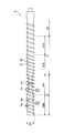
図2に示すように、スクリュー6は、中空のシャフト61とシャフト61の外周面に突出するように形成された螺旋状のフライト(羽根)62とを有している。フライト62に切欠が設けられていることでフライト62の螺旋形状は非連続になっており、シリンダー2の側面からシリンダー2の半径方向内側へと突出するように植え込まれたブレーカーボルト7と接触しないようになっている。ブレーカーボルト7が設けられていない場合には、フライト62の螺旋形状は連続的に形成することもできる。
図2に示す押出乾燥機10のスクリュー6は、第1ゾーン21および第2ゾーン22の2つのゾーンを有している。そして、第1ゾーン21は、搬送部21Aと、搬送部21Aにホッパー1側で隣接する圧縮部21Bとからなっており、ダイ3に最も近い第2ゾーン22は、搬送部22Aと、搬送部22Aにホッパー1側で隣接する圧縮部22Bとからなっている。また、第1ゾーン21のホッパー1側に隣接した区分は、ホッパー部25となっている。
本実施形態では、スクリュー6が、搬送部と圧縮部とからなるゾーン21、22を複数有していることにより、温度および圧力の上昇が段階的に行われ、高温および高圧となる箇所を分散させることができるので、ダイに隣接する圧縮部および搬送部の負荷変動を小さくすることができる。
水を多く含むゴム状重合体は固体としての性質を示すが、材料の均一性が低いために局所的に発熱しやすい。また、水を多く含むゴム状重合体は、熱伝導率が低いため温度分布や圧力分布が生じ、搬送が安定せず、サージング(押出乾燥機が逆流等により失速し、機能しなくなる現象)等を起こしやすい。このため、第1ゾーンで温度・圧力をかけて均一性を増し、第2ゾーンでさらに均一性を増すことで、搬送量、温度分布、圧力分布の均一性を段階的に高めることができ、均一な状態でエキスパンジョンさせることができる。その結果、ゴム状重合体が押出乾燥機のダイ3より出たときに、より均一な乾燥状態が得られる。複数のゾーンを設けることによるこの繰返しは、2以上あればよく、乾燥する材料の性質に応じて3以上の構成としてもよい。
本実施形態では、ダイ3に最も近い第2ゾーン22において、搬送部22Aにおけるシャフト61の外径(スクリュー6の内径)d2Aが、圧縮部22Bにおけるシャフト61の外径d2Bより小さくなっている。図示の押出乾燥機10では、スクリュー6の外径(フライト62の外径)Dは一定となっているので、第2ゾーン22におけるシャフト61の外径が上記関係を有することによって、第2搬送部22Aにおけるフライト62の高さh2Aを、第2圧縮部22Bにおけるフライト62の高さh2Bより大きくすることができる。なお、スクリュー6におけるフライト高さhは、スクリュー6の外半径(フライト62の外半径)D/2からシャフト61の外半径d/2を引いたものに相当する。
ここで、シリンダー2内でのゴム状重合体の移送において生成する熱量は、せん断速度の2乗に比例する。そして、せん断速度は、ゴム状重合体がせん断応力を受ける方向の速度、すなわち回転数に比例し、フライト高さhに反比例する。よって、フライト高さhを大きくすれば、せん断速度が小さくなり、生成する熱量も低くなる。したがって、上述のように第2搬送部22Aのシャフト外径d2Aを第2圧縮部22Bのシャフト外径d2Bより小さくすることによって、生成する熱量(不可避的に発生する熱量)を小さくすることができる。その結果、ゴム状重合体の過剰な温度上昇を防いで、変質(ゲル化)を抑制することができる。
さらに、第2ゾーン22において搬送部22Aのシャフト外径d2Aを圧縮部22Bのシャフト外径d2Bより小さくすることによって、第2ゾーン22の搬送部22Aの内部の容積(搬送部22Aに収容できる材料の体積)が大きくなり、搬送体積V2Aも大きくなる。その結果、第2ゾーン22における搬送部22Aの搬送体積V2Aの、圧縮部22Bの搬送体積V2Bに対する比の値(搬送体積比または圧縮比(V2A/V2B))を大きくすることができる。つまり、圧縮部22Bでのゴム状重合体の圧縮度合いを大きくすることができる。これにより、圧縮部通過後のゴム状重合体の圧力を高くすることができるので、押出し時の水分蒸発率を上げることができ、乾燥を促進させることが可能となる。例えば、40質量%程度の含水率(水分率)のゴム状重合体を押出乾燥させて、10質量%以下の含水率にすることができる。
このように、本実施形態によれば、過剰な温度上昇を抑えることによってゴム状重合体の劣化を防止しつつ、乾燥に必要な圧力を確保することができるので、高品質のゴム状重合体を安定して製造することができる。
また、本実施形態では、ダイ3に最も近いゾーンにおいて上記関係(d2A<d2B)を有しているため、製造において特に重要な押出し直前位置でのゴム状重合体の温度および圧力(或いは出口温度および出口圧力)を良好に制御することができる。
また、本実施形態によって不要な熱を抑制できることから、従来の構成に比べて、例えばスクリュー6の回転数Nを上げることが可能になる。これによって、単位時間当たりの乾燥ゴム状重合体の回収量を増加させることができ、生産性も高めることができる。
第2ゾーン22におけるスクリュー6のフライト62のピッチは、図2に示すように、ほぼ一定となっている。つまり、第2ゾーン22では、第2搬送部22Aと第2圧縮部22Bとでフライト62のピッチを相違させることによってではなく、シャフト61の外径dを相違させることによって、搬送体積比(V2A/V2B)を大きくしている。
なお、第2搬送部22Aにおけるフライト62のピッチを第2圧縮部22Bにおけるフライト62のピッチよりも大きくした場合、第2ゾーン22での搬送体積比(V2A/V2B)は大きくなるが、せん断速度が大きくなるため、発熱量は大きくなる。そのため、押出し直前でのゴム状重合体の温度が過度に上昇し、適切に制御できない可能性がある。
但し、第2搬送部22Aのシャフト外径d2Aを第2圧縮部22Bのシャフト外径d2Bより小さくして、不要な熱の発生が抑制されているのであれば、第2搬送部22Aと第2圧縮部22Bとで、フライト62のピッチを相違させてもよい。
第2ゾーン22における第2搬送部22Aのシャフト外径d2Aは、搬送部22Aのホッパー1側の端部からダイ3側の端部に亘って一定であることが好ましいが、設計上、図2に示すように、搬送部22Aの両端においてシャフト61にテーパが設けられていてもよい。その場合、ホッパー1側の端部とダイ3側の端部との間の、ほぼ一定となっている中央部分のシャフト外径を、シャフト外径d2Aとしてよい。
また、搬送体積についても、第2ゾーン22における第2搬送部22Aでは、スクリュー61のホッパー1側の端部とダイ3側の端部との間の、シャフト外径がほぼ一定となる中央部分における搬送体積を、搬送体積V2Aとしてよい。
本実施形態では、第2ゾーン22における圧縮部22Bのシャフト外径d2Bと搬送部22Aのシャフト外径d2Aとの比は、1:0.8~1:0.98であることが好ましく、1:0.85~1:0.96であるとより好ましい。1:0.98以下とすることで、乾燥機内での不要な発熱を抑制して過剰な温度上昇を回避しつつ、第2ゾーン22における搬送体積比(V2A/V2B)を大きくして乾燥のための圧力を確保する効果を高めることができる。よって、ゴム状重合体の劣化(ゲル化)を防ぎつつ、一層高い乾燥効率を得ることができる。また、1:0.8以上とすることで、ゴム状重合体の押出操作に十分なシャフト61の強度を確保することができる。
ダイ3に最も近い第2ゾーンにおいては、第2搬送部22Aのフライト61の幅(厚み)w2Aが、第2圧縮部22Bのフライト61の幅w2Bより小さくなっていると好ましい。これにより、第2搬送部22Aの内体積(搬送部22Aに収容できる材料の体積)を大きくすることができるため、第2ゾーン22における搬送体積比(V2A/V2B)を大きくすることができる。よって、第2搬送部22Aのフライト幅w2Aを第2圧縮部22Bのフライト61の幅w2Bより小さくした場合、搬送体積比(V2A/V2B)を大きくするという観点からは、その分だけ、搬送部22Aのシャフト外径d2Aを小さくする必要はなくなる。つまり、スクリュー6のシャフト61の強度を維持しつつ、搬送体積比(V2A/V2B)を大きくすることができる。
第2圧縮部22Bのフライトの幅w2Bと第2搬送部22Aのフライトの幅w2Aとの比は、押出乾燥機10およびスクリュー6のサイズにもよるが、1:0.4~1:0.8であると好ましく、1:0.45~1:0.6であるとより好ましい。1:0.8以下とすることで、搬送体積比を大きくし、押し出される直前のゴム状重合体の圧力を上昇させることができる。また、1:0.4以上とすることで、スクリュー6のシャフト61およびフライト62自体の強度を確保することができる。
なお、w2Aをw2Bより小さくしても、ゴム状重合体から第2搬送部22Aのフライト62が受ける圧力は、第2圧縮部22Bにおいてフライト62が受ける圧力よりも小さいので、フライト62の強度への影響は少ない。
また、本実施形態では、ダイに最も近い第2ゾーン22において、第2圧縮部22Bにおいてスクリューが1回転する際に搬送されるゴム状重合体の体積V2Bと、第2搬送部22Aにおいてスクリューが1回転する際に搬送されるゴム状重合体の体積V2Aとの比は、1:1を超えることが好ましい。例えば、1:1.1~1:5とすることが好ましく、1:1.5~1:2.5とすることがより好ましく、1:1.6~1:2.2とするとより好ましく、1:1.8~1:2.0とするとさらに好ましい。1:1.1以上とすることで、押し出される直前のゴム状重合体の圧力を高くすることができる。その結果、押し出されたゴム状重合体の水分が大気中で蒸発することを促進でき、含水率の小さい高品質のゴム状重合体を得ることができる。また、1:5以下とすることで、押出乾燥機の機械的な強度を維持することができる。
図2においては、第1ゾーン21は第2ゾーン22とは異なる構成を有している。すなわち、第1ゾーン21における第1搬送部21Aのシャフト外径は、第1圧縮部21Bのシャフト外径と同じである。また、第1搬送部21Aのフライト62のピッチは、第1圧縮部21Bのフライト62のピッチより大きく、第1搬送部21Aと第1圧縮部21Bとではフライト62の幅は等しくなっている。図示の例による第1ゾーン21では、搬送部と圧縮部とでフライト62のピッチを相違させることによって、搬送体積比を1より大きくしている。
しかし、第1ゾーン21は、上記以外の構成を有していてもよく、第2ゾーン22と同様の構成を有していてもよい。例えば、第1搬送部21Aにおけるシャフト外径を、第1圧縮部21Bにおけるシャフト外径より小さくすることができる。これにより、第2ゾーン22で得られるのと同様の効果、すなわち不要な発熱を抑えつつ、ゴム状重合体の乾燥も十分に促進させることができるという効果を第1ゾーン21でも得ることができ、さらに高品質のゴム状重合体を得ることができる。
その場合、第1ゾーン21においても、第2ゾーン22と同様に、圧縮部21Bのシャフト外径と搬送部21Aのシャフト外径との比を、1:0.8~1:0.98とすること好ましく、1:0.85~1:0.96とするとより好ましい。
また、第1ゾーン21において、圧縮部21Aにおいてスクリューが1回転する際に搬送されるゴム状重合体の体積と、搬送部21Bにおいてスクリューが1回転する際に搬送されるゴム状重合体の体積との比を1:1超とすることができる。また、この比は、1:1.5~1:2.5とすることが好ましく、1:1.6~1:2.2とするとより好ましく、1:1.8~1:2.0とするとさらに好ましい。
さらに、第1搬送部21Aのフライト幅が第1圧縮部21Bのフライト幅より小さくなっていてもよい。その比は、1:0.4~1:0.8であると好ましく、1:0.45~1:0.6であるとより好ましい。
図2の形態では搬送部と圧縮部とからなるゾーンは2つであるが、押出乾燥機10には、このようなゾーンが3つ以上あってもよい。この場合、ダイ3に最も近い第2ゾーン22よりも入口側に設けられている第1ゾーン21が複数あってもよい。その場合には、上記のように、複数の第1ゾーン21それぞれにおいて、搬送部21Aにおけるシャフト61の外径を、圧縮部21Bにおけるシャフト61の外径より小さくすることで、不要な発熱を抑えることができる。また、複数の第1ゾーン21それぞれにおいて搬送体積比を大きくすることができるので、ゴム状重合体が押し出される直前の圧力も十分に高く維持することができる。
なお、上述の形態では、シリンダー2の内径および外径、並びにスクリュー6の外径が軸線方向に一定であるものを用いているが、これらの径は必ずしも一定でなくともよい。上記径の1つ以上が軸線方向で変化している場合であっても、第2搬送部22Aのシャフト外径d2Aを第2圧縮部22Bのシャフト外径d2Bより小さくする、或いは、第2搬送部22Aのフライト高さh2Aを第2圧縮部22Bのフライト高さh2Bより大きくすることによって、押出乾燥機10内での過剰な発熱を抑えつつ、乾燥を良好に行うことができるという本願発明の効果を得ることができる。
本実施形態によって押出乾燥されるゴム状重合体の種類は、特に限定されないが、例えば、ブタジエンゴム(BR)、スチレン-ブタジエンゴム(SBR)、イソプレンゴム(IR)、スチレン-イソプレンブロックポリマー(SIS)、スチレン-ブタジエンブロックポリマー(SBS)、ニトリルブタジエンゴム(NBR)、クロロプレンゴム(CR)などのジエン系ゴム、ブチルゴム(IIR)、エチレン-プロピレン-ジエンターポリマーゴム(EPDM)、アクリルゴム、クロロスルホン化ポリエチレンゴム、フッ素ゴムなどのオレフィン系ゴム、シリコーンゴム、ウレタンゴムなどを例示することができる。これらの中でも、本実施形態は、BR、SBRの押出乾燥において好適に用いられる。
本実施形態では、上述の押出乾燥機10を用いてゴム状重合体を乾燥させるゴム状重合体の乾燥方法を提供する。また、本実施形態では、上述の押出乾燥機10を用いたゴム状重合体の製造方法も提供する。
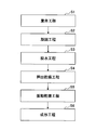
図3は、本発明の実施形態に係るゴム状重合体の製造方法の一例を示すフローチャートである。図3に示すように、本例のゴム状重合体の製造方法は、重合工程S1、凝固工程S2、脱水工程S3、押出乾燥工程S4、振動乾燥工程S5、成形工程S6を含む。
重合工程S1では、ブタジエン等のゴム原料を乳化重合、溶液重合等の重合反応により重合してゴム状重合体のラテックス、重合体溶液等を得る。凝固工程S2では、ゴム状重合体の溶液やラテックスをスチームストリッピング法により脱溶媒して、あるいは塩凝固させてゴム状重合体のスラリーを調製する。脱水工程S3では、ゴム状重合体のスラリーを押出機型スクイザー等の脱水機を用いて脱水し、所定の含水率を有するクラムを得る。
押出乾燥工程S4では、脱水したゴム状重合体のクラムを、上述の押出乾燥機10を用いて押出乾燥する。振動乾燥工程S5では、押出乾燥工程S4を経たゴム状重合体を、移動する振動ベルトに載せ、振動させながら加熱して乾燥する。ゴム状重合体の加熱は、ゴム状重合体に直接熱風を接触させたり、間接的に熱媒体を接触させたりすることにより行うことができる。
成形工程S6では、振動乾燥工程S5を経たゴム状重合体の質量を測定し、成形機を用いて所定の寸法のベールに成形する。ベールは、例えば、短辺36cm、長辺73cm、高さ18cmの寸法を有する直方体形状とすることができる。
本実施形態による乾燥方法またはゴム状重合体の製造方法においては、乾燥工程における不要な熱の発生を防ぐことにより、ゴム状重合体の均一な乾燥が可能になるため、ヒートロスを低減することができる。なお、ヒートロス(%)は、得られたゴム状重合体をサンプリングし、送風型乾燥機等により乾燥を行い、乾燥前後のゴム状重合体の質量を測定し、{[(乾燥前のゴム状重合体の質量)-(乾燥後のゴム状重合体の質量)]/(乾燥前のゴム状重合体の質量)}×100より求められる。
また、異常な温度上昇によるゴム状重合体の劣化を防止しつつ、高い出口圧力を確保してゴム状重合体中の水分の蒸発率を大きくすることができるので、高品質のゴム状重合体を得ることができる。さらに、ゴム状重合体を劣化させることなく、より高い回転数Nでの操作が可能になるため、生産効率も高めることができる。
[ブタジエンゴム(BR)の乾燥・製造]
(実施例1)
押出乾燥機10として、エクスパンション型押出乾燥機(ライナー内径355mm、回転数60~300rpm、内部圧力0.01~6MPaG)を用いた。押出乾燥機10のスクリュー6は、図2に示す構成を有するものを使用し、そのスクリュー外径は352mmであった。
(実施例1)
押出乾燥機10として、エクスパンション型押出乾燥機(ライナー内径355mm、回転数60~300rpm、内部圧力0.01~6MPaG)を用いた。押出乾燥機10のスクリュー6は、図2に示す構成を有するものを使用し、そのスクリュー外径は352mmであった。
スクリュー6のシャフト外径(フライト外径)は、第1搬送部21Aのみにおいて257mmとし、それ以外の区分(ホッパー部25、第1搬送部21A、第1圧縮部21B、第2圧縮部22B)においては273mmとした。また、スクリュー6のフライト幅は、第2搬送部22Aのみにおいて15mmとし、それ以外(ホッパー部25、第1搬送部21A、第1圧縮部21B、第2圧縮部22B)において31mmとした。
スクリュー1回転当たりのゴム状重合体の搬送体積は、ホッパー部25において5293cm3、第1搬送部21Aで2300cm3、第1圧縮部21Bで987cm3、第2搬送部22Aで1584cm3、第2圧縮部22Bで987cm3とした。
ゴム状重合体としては、溶液重合により製造されたブタジエンゴム(BR)を、スチームストリッピング法によって脱溶媒して凝固させ、脱水機により脱水したもの(クラム)を準備した。脱水機による脱水後のブタジエンゴム(BR)の含水率は、12%であった。
上記の押出乾燥機10を、ダイ温度が約150℃となるように制御しながら、上記のゴム状重合体の押出乾燥を行った。
押出乾燥工程後のブタジエンゴム(BR)の含水率は、4.8%であった。また、運転中のシャフト回転数N(rpm)、回収量Q(kg/h)を平均値で記録した。
押出乾燥工程後、さらに振動乾燥工程および成形工程を行って、ベール(短辺36cm×長辺73cm×高さ18cm程度)を得た。このゴム状重合体のベールについて、目視で乾燥評価を行った。乾燥評価は、具体的には、製造時間1時間あたりに得られたベールについて、その表面に現れている直径10mm以上の白色の箇所(白色部分)の数を目視にて数えることにより行った。ゴム状重合体は、十分な乾燥が行われていれば、ベールの色は均一な黄色となるはずであるが、水分が残っているとその部分は光の散乱によって白色部分として観察される。よって、ベールの白色部分の個数が少ないほど乾燥が十分に行われており、その数が多いほど乾燥が不十分であったことを示す。
また、成形工程後にサンプリングしたゴム状重合体(ベール)について、送風型乾燥機(105℃、1時間)により含水率を測定し、ヒートロス(%)を算出した。ヒートロスは、{[(成形工程後に得られたサンプルの質量)-(送風型乾燥機による乾燥後のサンプルの質量)]/(成形工程後に得られたサンプルの質量)}×100より求めた。
押出乾燥の条件および結果を表1、2に示す。


第2搬送部22Aにおけるスクリュー6のシャフト外径d2Aを244mmに変更し、第2搬送部22Aにおけるスクリュー1回転当たりのゴム状重合体の搬送体積V2Aを1809cm3としたこと以外は、実施例1と同様にしてゴム状重合体の製造を行い、同様の評価を行った。
(比較例1)
第2搬送部22Aにおけるスクリュー6のシャフト外径d2Aを273mmに変更し、第2搬送部22Aのフライト幅w2Aを31mmに変更し、第2搬送部22Aにおけるスクリュー1回転当たりのゴム状重合体の搬送体積V2Aを980cm3としたこと以外は、実施例1と同じ条件でゴム状重合体の製造を行い、同様の評価を行った。
第2搬送部22Aにおけるスクリュー6のシャフト外径d2Aを273mmに変更し、第2搬送部22Aのフライト幅w2Aを31mmに変更し、第2搬送部22Aにおけるスクリュー1回転当たりのゴム状重合体の搬送体積V2Aを980cm3としたこと以外は、実施例1と同じ条件でゴム状重合体の製造を行い、同様の評価を行った。
なお、比較例1においては、スクリュー全体を通して(ホッパー部25、第1搬送部21A、第1圧縮部21B、第2搬送部22A、第2圧縮部22Bにおいて)、シャフト外径及びフライト幅が一定となっている。
(比較例2)
第2搬送部22Aにおけるスクリュー6のシャフト外径d2Aを273mmに変更し、第2搬送部22Aのフライト幅w2Aを31mmに変更し、第2搬送部22Aにおけるスクリュー1回転当たりのゴム状重合体の搬送体積V2Aを980cm3とし、さらに第1搬送部21Aのフライトのピッチを変更して第1搬送部21Aの搬送体積V1Aを980cm3としたこと以外は、実施例1と同じ条件でゴム状重合体の製造を行い、同様の評価を行った。
第2搬送部22Aにおけるスクリュー6のシャフト外径d2Aを273mmに変更し、第2搬送部22Aのフライト幅w2Aを31mmに変更し、第2搬送部22Aにおけるスクリュー1回転当たりのゴム状重合体の搬送体積V2Aを980cm3とし、さらに第1搬送部21Aのフライトのピッチを変更して第1搬送部21Aの搬送体積V1Aを980cm3としたこと以外は、実施例1と同じ条件でゴム状重合体の製造を行い、同様の評価を行った。
なお、比較例2においても、スクリュー全体を通して(ホッパー部25、第1搬送部21A、第1圧縮部21B、第2搬送部22A、第2圧縮部22Bにおいて)シャフト外径及びフライト幅は一定となっている。また、比較例2においては、第1ゾーン21および第2ゾーン22で、搬送体積比は等しい。
表1、2より、第2ゾーン22における第2搬送部22Aのシャフト外径d2Aを第2圧縮部22Bのシャフト外径d2Bより小さくした実施例1、2では、比較例1に比べて、得られたゴム状重合体で観察される白色箇所の数が小さく、またヒートロスも低く、均一にかつ十分に乾燥された高品質のゴム状重合体が得られることが分かった。
さらに、実施例1、2の回転数Nは比較例1より高くなっている。また、回収量Qも高くなっており、生産性が向上していることが分かる。これは、実施例1、2では、異常な熱の発生を抑制できたため、高い回転数Nであっても高品質のゴム状重合体を得ることができたことを示す。
一方、第2ゾーン22における第2搬送部22Aと第2圧縮部22Bとでシャフト外径が同じである比較例1、2では、実施例1、2と比較して品質の良いゴム状重合体は得られなかった。すなわち、比較例1では、ダイ温度の制御は良好にできたものの、得られたゴム状重合体のベールの白色箇所の数が多く、またヒートロスも高く、実施例1、2と比較して水分が多いことが分かる。比較例2においては、150℃のダイ温度を制御することができず、ゴム状重合体の劣化が起こり、ゲル化が観察された。なお、比較例2はゲル化し、その後の製造工程を続けることができなかったため、ヒートロスの算出はしていない。
[スチレン-ブタジエンゴム(SBR)の乾燥・製造]
(実施例3)
ゴム状重合体の種類として、溶液重合により製造されたスチレン-ブタジエンゴム(SBR)を用い、ダイ温度が約160℃となるよう押出乾燥機10を制御したこと以外は、実施例1と同様にして製造を行い、実施例1と同様の評価を行った。
(実施例3)
ゴム状重合体の種類として、溶液重合により製造されたスチレン-ブタジエンゴム(SBR)を用い、ダイ温度が約160℃となるよう押出乾燥機10を制御したこと以外は、実施例1と同様にして製造を行い、実施例1と同様の評価を行った。
なお、脱水機による脱水後のスチレン-ブタジエンゴム(SBR)の含水率は、約16%であった。また、押出乾燥工程後のスチレン-ブタジエンゴム(SBR)の含水率は、5.2%であった。
(実施例4)
第2搬送部22Aにおけるスクリュー6のシャフト外径d2Aを244mmに変更し、第2搬送部22Aにおけるスクリュー1回転当たりのゴム状重合体の搬送体積V2Aを1809cm3としたこと以外は、実施例3と同様にしてゴム状重合体の製造を行い、同様の評価を行った。
第2搬送部22Aにおけるスクリュー6のシャフト外径d2Aを244mmに変更し、第2搬送部22Aにおけるスクリュー1回転当たりのゴム状重合体の搬送体積V2Aを1809cm3としたこと以外は、実施例3と同様にしてゴム状重合体の製造を行い、同様の評価を行った。
(比較例3)
第2搬送部22Aにおけるスクリュー6のシャフト外径d2Aを273mmに変更し、第2搬送部22Aのフライト幅w2Aを31mmに変更し、第2搬送部22Aにおけるスクリュー1回転当たりのゴム状重合体の搬送体積V2Aを980cm3としたこと以外は、実施例3と同じ条件でゴム状重合体の製造を行い、同様の評価を行った。
第2搬送部22Aにおけるスクリュー6のシャフト外径d2Aを273mmに変更し、第2搬送部22Aのフライト幅w2Aを31mmに変更し、第2搬送部22Aにおけるスクリュー1回転当たりのゴム状重合体の搬送体積V2Aを980cm3としたこと以外は、実施例3と同じ条件でゴム状重合体の製造を行い、同様の評価を行った。
なお、比較例3においては、スクリュー全体を通して(ホッパー部25、第1搬送部21A、第1圧縮部21B、第2搬送部22A、第2圧縮部22Bにおいて)、シャフト外径及びフライト幅は一定となっている。
(比較例4)
第2搬送部22Aにおけるスクリュー6のシャフト外径d2Aを273mmに変更し、第2搬送部22Aのフライト幅w2Aを31mmに変更し、第2搬送部22Aにおけるスクリュー1回転当たりのゴム状重合体の搬送体積V2Aを980cm3とし、さらに第1搬送部21Aのフライトのピッチを変更して第1搬送部21Aの搬送体積V1Aを980cm3としたこと以外は、実施例3と同じ条件でゴム状重合体の製造を行い、同様の評価を行った。
第2搬送部22Aにおけるスクリュー6のシャフト外径d2Aを273mmに変更し、第2搬送部22Aのフライト幅w2Aを31mmに変更し、第2搬送部22Aにおけるスクリュー1回転当たりのゴム状重合体の搬送体積V2Aを980cm3とし、さらに第1搬送部21Aのフライトのピッチを変更して第1搬送部21Aの搬送体積V1Aを980cm3としたこと以外は、実施例3と同じ条件でゴム状重合体の製造を行い、同様の評価を行った。
なお、比較例4においても、スクリュー全体を通して(ホッパー部25、第1搬送部21A、第1圧縮部21B、第2搬送部22A、第2圧縮部22Bにおいて)、シャフト外径及びフライト幅は一定となっている。また、比較例4においては、第1ゾーン21および第2ゾーン22で、搬送体積比は等しい。
表1、2より、第2ゾーン22における第2搬送部22Aのシャフト外径d2Aを第2圧縮部22Bのシャフト外径d2Bより小さくした実施例3、4では、比較例3に比べて、得られたゴム状重合体で観察される白色箇所の数が小さく、またヒートロスも小さく、均一かつ十分に乾燥された高品質のゴム状重合体が得られることが分かった。
さらに、実施例3、4の回転数Nは比較例3より高くなっている。また、回収量Qも高くなっており、生産性が向上していることが分かる。これは、実施例3、4では異常な熱の発生を抑制できたため、高い回転数Nであっても高品質のゴム状重合体を得ることができたことを示す。
一方、第2ゾーン22における第2搬送部22Aと第2圧縮部22Bとでシャフト外径が同じである比較例3、4では、実施例3、4と比較して品質の良いゴム状重合体は得られなかった。すなわち、比較例3では、ダイ温度の制御はできたものの、得られたゴム状重合体のベールの白色箇所の数が多く、またヒートロスも高く、実施例3、4に比べて水分が多いことが分かる。比較例4においては、160℃のダイ温度を制御することができず、ゴム状重合体の劣化が起こり、ゲル化が観察された。なお、比較例4はゲル化し、その後の製造工程を続けることができなかったため、ヒートロスの算出はしていない。
本出願は、2016年11月4日に日本国特許庁に出願された特願2016-216702号に基づく優先権を主張するものであり、その全内容は参照をもってここに援用される。
1 ホッパー
2 シリンダー
3 ダイ
4 駆動装置
6 スクリュー
7 ブレーカーボルト
9 カッター
10 押出乾燥機
61 シャフト
62 フライト
21 第1ゾーン
21A 第1搬送部
21B 第1圧縮部
22 第2ゾーン
22A 第2搬送部
22B 第2圧縮部
25 供給部
D フライト外径(スクリュー外径)
d シャフト外径(スクリュー内径)
h フライト高さ
w フライト幅
2 シリンダー
3 ダイ
4 駆動装置
6 スクリュー
7 ブレーカーボルト
9 カッター
10 押出乾燥機
61 シャフト
62 フライト
21 第1ゾーン
21A 第1搬送部
21B 第1圧縮部
22 第2ゾーン
22A 第2搬送部
22B 第2圧縮部
25 供給部
D フライト外径(スクリュー外径)
d シャフト外径(スクリュー内径)
h フライト高さ
w フライト幅
Claims (6)
- ゴム状重合体が投入されるホッパーを一端に有し、ダイを他端に有するシリンダーと、
前記シリンダー内に回転可能に配置され、シャフトと当該シャフトの外周面に形成された螺旋状のフライトとを有するスクリューと
を備えたゴム状重合体用押出乾燥機であって、
前記スクリューが、搬送部と圧縮部とからなるゾーンを複数備え、
前記ダイに最も近いゾーンにおいて、前記搬送部におけるシャフトの外径が、前記圧縮部におけるシャフトの外径より小さい、ゴム状重合体用押出乾燥機。 - 前記ダイに最も近いゾーンにおいて、前記圧縮部におけるシャフトの外径と前記搬送部におけるシャフトの外径との比が、1:0.8~1:0.98である、請求項1に記載のゴム状重合体用押出乾燥機。
- 前記ダイに最も近いゾーンにおいて、前記圧縮部においてスクリューが1回転する際に搬送されるゴム状重合体の体積と、前記搬送部においてスクリューが1回転する際に搬送されるゴム状重合体の体積との値が、1:1.5以上である、請求項1または2に記載のゴム状重合体用押出乾燥機。
- 前記ダイに最も近いゾーンにおいて、前記搬送部におけるフライトの幅が、前記圧縮部におけるフライトの幅より小さい、請求項1から3のいずれか一項に記載のゴム状重合体用押出乾燥機。
- ゴム状重合体が投入されるホッパーを一端に有し、ダイを他端に有するシリンダーと、
前記シリンダー内に回転可能に配置され、シャフトと当該シャフトの外周面に形成された螺旋状のフライトとを有するスクリューとを備えた押出乾燥機を用いてゴム状重合体を乾燥させるゴム状重合体の乾燥方法であって、
前記スクリューが、搬送部と圧縮部とからなるゾーンを複数備えており、
前記ダイに最も近いゾーンにおいて、前記搬送部におけるシャフトの外径が、前記圧縮部におけるシャフトの外径より小さい押出乾燥機を用いてゴム状重合体を乾燥させる、ゴム状重合体の乾燥方法。 - ゴム状重合体のラテックスまたは重合体溶液を凝固させてゴム状重合体のスラリーを調製する凝固工程と、
前記スラリーを脱水する脱水工程と、
前記脱水したゴム状重合体を押出乾燥する乾燥工程とを有し、
前記乾燥工程は、押出乾燥機によって押出乾燥を行うことを含み、
前記押出乾燥機は、ゴム状重合体が投入されるホッパーを一端に有し、ダイを他端に有するシリンダーと、前記シリンダー内に回転可能に配置され、シャフトと当該シャフトの外周面に形成された螺旋状のフライトとを有するスクリューとを備え、
前記スクリューが、搬送部と圧縮部とからなるゾーンを複数備えており、
前記ダイに最も近いゾーンにおいて、前記搬送部におけるシャフトの外径が、前記圧縮部におけるシャフトの外径より小さい、ゴム状重合体の製造方法。
Priority Applications (4)
| Application Number | Priority Date | Filing Date | Title |
|---|---|---|---|
| US16/343,616 US11680112B2 (en) | 2016-11-04 | 2017-10-23 | Extrusion dryer for rubbery polymer, drying method of rubbery polymer, and production method of rubbery polymer |
| SG11201903507UA SG11201903507UA (en) | 2016-11-04 | 2017-10-23 | Extrusion dryer for rubbery polymer, drying method of rubbery polymer, and production method of rubbery polymer |
| CN201780064172.7A CN109843530A (zh) | 2016-11-04 | 2017-10-23 | 橡胶状聚合物用挤出干燥机、橡胶状聚合物的干燥方法和橡胶状聚合物的制造方法 |
| JP2018548945A JP7003933B2 (ja) | 2016-11-04 | 2017-10-23 | ゴム状重合体用押出乾燥機、ゴム状重合体の乾燥方法、およびゴム状重合体の製造方法 |
Applications Claiming Priority (2)
| Application Number | Priority Date | Filing Date | Title |
|---|---|---|---|
| JP2016216702 | 2016-11-04 | ||
| JP2016-216702 | 2016-11-04 |
Publications (1)
| Publication Number | Publication Date |
|---|---|
| WO2018084015A1 true WO2018084015A1 (ja) | 2018-05-11 |
Family
ID=62076563
Family Applications (1)
| Application Number | Title | Priority Date | Filing Date |
|---|---|---|---|
| PCT/JP2017/038199 Ceased WO2018084015A1 (ja) | 2016-11-04 | 2017-10-23 | ゴム状重合体用押出乾燥機、ゴム状重合体の乾燥方法、およびゴム状重合体の製造方法 |
Country Status (5)
| Country | Link |
|---|---|
| US (1) | US11680112B2 (ja) |
| JP (1) | JP7003933B2 (ja) |
| CN (1) | CN109843530A (ja) |
| SG (1) | SG11201903507UA (ja) |
| WO (1) | WO2018084015A1 (ja) |
Citations (6)
| Publication number | Priority date | Publication date | Assignee | Title |
|---|---|---|---|---|
| JPS5636539A (en) * | 1979-09-03 | 1981-04-09 | Toray Ind Inc | Moldable resin composition |
| JPH0550424A (ja) * | 1991-08-27 | 1993-03-02 | Kobe Steel Ltd | 2軸押出機 |
| JP2003164746A (ja) * | 2001-11-29 | 2003-06-10 | Kobe Steel Ltd | ゴムあるいはゴム系組成物の混練装置 |
| JP2003266435A (ja) * | 2002-03-13 | 2003-09-24 | Nippon Zeon Co Ltd | アロイの製造方法 |
| JP2013522433A (ja) * | 2010-03-24 | 2013-06-13 | ランクセス・インターナショナル・ソシエテ・アノニム | 水および溶媒を含まないポリマーの製造方法 |
| JP2016003316A (ja) * | 2014-06-19 | 2016-01-12 | 東洋ゴム工業株式会社 | ゴムウエットマスターバッチの製造方法およびゴムウエットマスターバッチ、ならびにゴムウエットマスターバッチを含有するゴム組成物 |
Family Cites Families (5)
| Publication number | Priority date | Publication date | Assignee | Title |
|---|---|---|---|---|
| US4304054A (en) * | 1980-04-21 | 1981-12-08 | The B. F. Goodrich Company | Screw press for drying elastomeric polymers |
| NL1007534C2 (nl) * | 1996-12-03 | 1999-05-12 | Japan Elastomer Co | Rubberachtig polymeer alsmede werkwijze voor de bereiding daarvan. |
| EP1316399B1 (en) * | 2001-11-29 | 2010-10-06 | Kabushiki Kaisha Kobe Seiko Sho (Kobe Steel, Ltd.) | Kneading apparatus |
| KR20070087614A (ko) | 2004-11-19 | 2007-08-28 | 제이에스알 가부시끼가이샤 | 함수 중합체의 건조 방법 |
| US20200031959A1 (en) * | 2017-03-27 | 2020-01-30 | Zeon Corporation | Rubbery polymer extrusion dryer, method of drying rubbery polymer, and method of producing rubbery polymer |
-
2017
- 2017-10-23 SG SG11201903507UA patent/SG11201903507UA/en unknown
- 2017-10-23 WO PCT/JP2017/038199 patent/WO2018084015A1/ja not_active Ceased
- 2017-10-23 JP JP2018548945A patent/JP7003933B2/ja active Active
- 2017-10-23 US US16/343,616 patent/US11680112B2/en active Active
- 2017-10-23 CN CN201780064172.7A patent/CN109843530A/zh not_active Withdrawn
Patent Citations (6)
| Publication number | Priority date | Publication date | Assignee | Title |
|---|---|---|---|---|
| JPS5636539A (en) * | 1979-09-03 | 1981-04-09 | Toray Ind Inc | Moldable resin composition |
| JPH0550424A (ja) * | 1991-08-27 | 1993-03-02 | Kobe Steel Ltd | 2軸押出機 |
| JP2003164746A (ja) * | 2001-11-29 | 2003-06-10 | Kobe Steel Ltd | ゴムあるいはゴム系組成物の混練装置 |
| JP2003266435A (ja) * | 2002-03-13 | 2003-09-24 | Nippon Zeon Co Ltd | アロイの製造方法 |
| JP2013522433A (ja) * | 2010-03-24 | 2013-06-13 | ランクセス・インターナショナル・ソシエテ・アノニム | 水および溶媒を含まないポリマーの製造方法 |
| JP2016003316A (ja) * | 2014-06-19 | 2016-01-12 | 東洋ゴム工業株式会社 | ゴムウエットマスターバッチの製造方法およびゴムウエットマスターバッチ、ならびにゴムウエットマスターバッチを含有するゴム組成物 |
Also Published As
| Publication number | Publication date |
|---|---|
| JP7003933B2 (ja) | 2022-01-21 |
| CN109843530A (zh) | 2019-06-04 |
| SG11201903507UA (en) | 2019-05-30 |
| US20200048374A1 (en) | 2020-02-13 |
| JPWO2018084015A1 (ja) | 2019-09-19 |
| US11680112B2 (en) | 2023-06-20 |
Similar Documents
| Publication | Publication Date | Title |
|---|---|---|
| KR100743476B1 (ko) | 원추형 이축 스크류 압출기 및 탈수기 | |
| JP6130586B2 (ja) | エラストマー含有媒体から揮発性成分を除去する方法、およびそのための脱ガス装置 | |
| CN1172724A (zh) | 同方向旋转双轴挤出机的高熔点树脂脱水系统 | |
| US3578740A (en) | Dewatering pelletizer apparatus | |
| JP4527800B1 (ja) | ウェットマスターバッチの製造方法 | |
| JP5956156B2 (ja) | 多軸混練押出機、及びウエットマスターバッチの製造方法 | |
| WO2018084015A1 (ja) | ゴム状重合体用押出乾燥機、ゴム状重合体の乾燥方法、およびゴム状重合体の製造方法 | |
| JP2012131943A (ja) | ウェットマスターバッチの製造方法及びタイヤ用ゴム組成物及び空気入りタイヤ | |
| EP0850741B1 (en) | Dewatering and drying of EP(D)M | |
| US20200031959A1 (en) | Rubbery polymer extrusion dryer, method of drying rubbery polymer, and method of producing rubbery polymer | |
| US3360820A (en) | Process and apparatus for working and disintegrating synthetic rubber | |
| TWI515100B (zh) | Rubber-like polymer extrusion drying apparatus and rubber-like polymer | |
| JP7275957B2 (ja) | 連続生産可能なアクリルゴムの製造方法 | |
| US20190255739A1 (en) | Rubbery polymer extrusion dryer, method of drying rubbery polymer, and method of manufacturing rubbery polymer | |
| CN219347055U (zh) | 用于sbs装置的离心脱水干燥机 | |
| CN211440734U (zh) | 一种废旧橡胶回收用塑化装置 | |
| KR101620143B1 (ko) | 고분자 라텍스의 탈수장치 | |
| KR20030064131A (ko) | 가연성폐기물 건조 및 열분해 성형장치 | |
| JP2001205627A (ja) | 押出機、ペレット製造装置およびペレット製造方法 | |
| KR102504599B1 (ko) | 고분자 라텍스의 탈수장치 | |
| JP2021036009A (ja) | 合成ゴムの製造方法 | |
| JP2010248327A (ja) | ゴム組成物の調製方法 | |
| JP2003160611A (ja) | 重合体の回収方法および回収装置 | |
| RU2624646C1 (ru) | Способ экструзионной сушки галобутилкаучуков | |
| KR200275230Y1 (ko) | 가연성폐기물 건조 및 열분해 성형장치 |
Legal Events
| Date | Code | Title | Description |
|---|---|---|---|
| 121 | Ep: the epo has been informed by wipo that ep was designated in this application |
Ref document number: 17868337 Country of ref document: EP Kind code of ref document: A1 |
|
| ENP | Entry into the national phase |
Ref document number: 2018548945 Country of ref document: JP Kind code of ref document: A |
|
| NENP | Non-entry into the national phase |
Ref country code: DE |
|
| 122 | Ep: pct application non-entry in european phase |
Ref document number: 17868337 Country of ref document: EP Kind code of ref document: A1 |