WO2018079733A1 - 正浸透膜およびその用途 - Google Patents
正浸透膜およびその用途 Download PDFInfo
- Publication number
- WO2018079733A1 WO2018079733A1 PCT/JP2017/038973 JP2017038973W WO2018079733A1 WO 2018079733 A1 WO2018079733 A1 WO 2018079733A1 JP 2017038973 W JP2017038973 W JP 2017038973W WO 2018079733 A1 WO2018079733 A1 WO 2018079733A1
- Authority
- WO
- WIPO (PCT)
- Prior art keywords
- forward osmosis
- osmosis membrane
- acid group
- membrane
- semipermeable membrane
- Prior art date
- Legal status (The legal status is an assumption and is not a legal conclusion. Google has not performed a legal analysis and makes no representation as to the accuracy of the status listed.)
- Ceased
Links
Images

Classifications
-
- B—PERFORMING OPERATIONS; TRANSPORTING
- B01—PHYSICAL OR CHEMICAL PROCESSES OR APPARATUS IN GENERAL
- B01D—SEPARATION
- B01D69/00—Semi-permeable membranes for separation processes or apparatus characterised by their form, structure or properties; Manufacturing processes specially adapted therefor
- B01D69/12—Composite membranes; Ultra-thin membranes
- B01D69/1213—Laminated layers
-
- B—PERFORMING OPERATIONS; TRANSPORTING
- B01—PHYSICAL OR CHEMICAL PROCESSES OR APPARATUS IN GENERAL
- B01D—SEPARATION
- B01D61/00—Processes of separation using semi-permeable membranes, e.g. dialysis, osmosis or ultrafiltration; Apparatus, accessories or auxiliary operations specially adapted therefor
-
- B—PERFORMING OPERATIONS; TRANSPORTING
- B01—PHYSICAL OR CHEMICAL PROCESSES OR APPARATUS IN GENERAL
- B01D—SEPARATION
- B01D69/00—Semi-permeable membranes for separation processes or apparatus characterised by their form, structure or properties; Manufacturing processes specially adapted therefor
- B01D69/02—Semi-permeable membranes for separation processes or apparatus characterised by their form, structure or properties; Manufacturing processes specially adapted therefor characterised by their properties
-
- B—PERFORMING OPERATIONS; TRANSPORTING
- B01—PHYSICAL OR CHEMICAL PROCESSES OR APPARATUS IN GENERAL
- B01D—SEPARATION
- B01D69/00—Semi-permeable membranes for separation processes or apparatus characterised by their form, structure or properties; Manufacturing processes specially adapted therefor
- B01D69/10—Supported membranes; Membrane supports
- B01D69/107—Organic support material
- B01D69/1071—Woven, non-woven or net mesh
-
- B—PERFORMING OPERATIONS; TRANSPORTING
- B01—PHYSICAL OR CHEMICAL PROCESSES OR APPARATUS IN GENERAL
- B01D—SEPARATION
- B01D71/00—Semi-permeable membranes for separation processes or apparatus characterised by the material; Manufacturing processes specially adapted therefor
- B01D71/06—Organic material
- B01D71/52—Polyethers
- B01D71/522—Aromatic polyethers
-
- C—CHEMISTRY; METALLURGY
- C08—ORGANIC MACROMOLECULAR COMPOUNDS; THEIR PREPARATION OR CHEMICAL WORKING-UP; COMPOSITIONS BASED THEREON
- C08G—MACROMOLECULAR COMPOUNDS OBTAINED OTHERWISE THAN BY REACTIONS ONLY INVOLVING UNSATURATED CARBON-TO-CARBON BONDS
- C08G65/00—Macromolecular compounds obtained by reactions forming an ether link in the main chain of the macromolecule
- C08G65/34—Macromolecular compounds obtained by reactions forming an ether link in the main chain of the macromolecule from hydroxy compounds or their metallic derivatives
- C08G65/38—Macromolecular compounds obtained by reactions forming an ether link in the main chain of the macromolecule from hydroxy compounds or their metallic derivatives derived from phenols
Definitions
- the semipermeable membrane is useful for selectively separating a predetermined component from a liquid mixture or a gas mixture, and is suitably used, for example, for producing high-purity water or separating a specific solute from a solution.
- the reverse osmosis method which is the mainstream in the past, exposes the reverse osmosis membrane to high pressure. Therefore, as a reverse osmosis membrane, in order to obtain high strength, a porous support (for example, non-woven fabric), a porous polymer layer (for example, polysulfone layer), and a layer that actually functions as a semipermeable membrane (skin layer, separation layer) A composite semipermeable membrane obtained by laminating in this order is the mainstream.
- a porous support for example, non-woven fabric
- a porous polymer layer for example, polysulfone layer
- a layer that actually functions as a semipermeable membrane skin layer, separation layer
- the effective support layer for forward osmosis membranes should be as thin and highly porous as possible because it is not applicable to forward osmosis due to reduced water flux and high salt leakage in the process) And that a direct path from the driving solution to the active surface of the membrane should be provided.
- the driving force when water moves from the low concentration side (for example, fresh water) to the high concentration side (for example, seawater) in the forward osmosis method is the osmotic pressure generated between aqueous solutions of different concentrations separated by the forward osmosis membrane. is there. If the thickness of the porous support layer or the porous polymer layer is large, or if the concentration polarization around or inside the forward osmosis membrane is large, the difference in concentration between the two solutions is substantially near the skin layer. As a result, the osmotic pressure is reduced, the driving force is reduced, and the permeation flux is reduced.
- Patent Document 2 discloses a forward osmosis membrane having a nonwoven fabric, a polymer layer formed thereon, and a polyamide-based dense layer formed thereon.
- this forward osmosis membrane the concentration polarization in the membrane due to the thickness of the nonwoven fabric and the polymer layer as a support is increased by applying a thin nonwoven fabric made of long fibers and a thin polymer layer.
- the permeation flux in the forward osmosis method is improved.
- Patent Document 3 discloses a microporous support in a composite semipermeable membrane composed of a fibrous support layer, a microporous support membrane, and a crosslinked polyamide thin film layer that can be used as a forward osmosis membrane for concentration difference power generation.
- a microporous support in a composite semipermeable membrane composed of a fibrous support layer, a microporous support membrane, and a crosslinked polyamide thin film layer that can be used as a forward osmosis membrane for concentration difference power generation.
- the conventional forward osmosis membrane has room for further improvement in terms of expressing high water permeability and high salt rejection.
- the skin layer in the conventional composite semipermeable membrane cannot be produced as a free-standing film, and is formed by applying a film forming material on a porous substrate.
- a film forming material In order to achieve high water permeability, it is desirable that the forward osmosis membrane or the skin layer is thin.
- the applied film-forming material soaks into the base material, or unevenness such as nonwoven fabric affects it. Therefore, it was difficult to produce a thin skin layer without defects.
- a semipermeable membrane using a specific aromatic polyether resin having a proton acid group as a raw material can be produced as a self-supporting membrane, and this semipermeable membrane and a specific porous substrate
- a forward osmosis membrane having a high water permeability and a high salt rejection can be produced by laminating and, and the present invention has been completed.
- the gist of the present invention is as follows.
- a forward osmosis membrane comprising a semipermeable membrane and a porous substrate disposed on at least one surface thereof,
- the semipermeable membrane comprises a protonic acid group-containing aromatic polyether resin including a structural unit (1) represented by the following formula (1) and a structural unit (2) represented by the following formula (2).
- the porous substrate is a forward osmosis membrane having an air permeability of 100 to 400 cm 3 / cm 2 / s and a thickness of 50 to 700 ⁇ m measured by A method (Fragile type method) described in JIS L 1096.
- X 1 to X 5 are each independently H, Cl, F, CF 3 or a protonic acid group, At least one of X 1 to X 5 is a protonic acid group; X 1 to X 5 may each be present in two or more in an aromatic ring, and when two or more protonic acid groups are present in one aromatic ring, each protonic acid group may be the same as or different from each other. It may be.
- a 1 to A 6 are each independently a direct bond, —CH 2 —, —C (CH 3 ) 2 —, —C (CF 3 ) 2 —, —O— or —CO—.
- FIG. 1 is a schematic diagram of an apparatus used for evaluating the separation performance of a forward osmosis membrane in Examples.
- the forward osmosis membrane according to the present invention includes a semipermeable membrane and a porous substrate disposed on at least one surface thereof.
- the semipermeable membrane comprises a protonic acid group-containing aromatic polyether resin.
- the protonic acid group-containing aromatic polyether resin contains a structural unit represented by the following formula (1) and a structural unit (2) represented by the following formula (2).
- i, j, k and l each independently represent 0 or 1;
- R 1 to R 10 may be present in each aromatic ring, and when two or more C m H 2m + 1 are present in one aromatic ring, each C m H 2m + 1 is They may be the same or different.
- X 1 to X 5 are each independently H, Cl, F, CF 3 or a protonic acid group.
- At least one of X 1 to X 5 is a protonic acid group.
- Examples of the structural unit (1) include structural units represented by the following formula (1-1) or the following formula (1-2). In these structures, A 1 is —CO—. Is preferred,
- the resin can be obtained by condensation polymerization with a monomer having a hydroxyl group represented by:
- Y is a halogen atom, and the meanings of the other symbols are the same as the meanings of the same symbols used in the above formulas (1) and (2).
- Preferred examples of the halogen atom include fluorine and chlorine.
- the solvent examples include, but are not limited to, water, alcohols such as methanol, ethanol, 1-propanol, 2-propanol and butanol, hydrocarbons such as toluene and xylene, and halogenated carbonization such as methyl chloride and methylene chloride.
- ethers such as dichloroethyl ether, 1,4-dioxane and tetrahydrofuran
- fatty acid esters such as methyl acetate and ethyl acetate
- ketones such as acetone and methyl ethyl ketone
- cellosolve such as 2-methoxyethanol and 2-ethoxyethanol
- aprotic polar solvents such as N, N-dimethylacetamide, N-methyl-2-pyrrolidone, dimethyl sulfoxide and dimethyl carbonate.
- the semipermeable membrane is substantially composed of only the protonic acid group-containing aromatic polyether resin, but a small amount of other components (for example, 1% by mass or less, or 0.1% by mass) does not impair the effects of the present invention. (Mass% or less) may be included.
- the tensile elastic modulus of the semipermeable membrane is preferably 0.8 to 2.0 GPa, more preferably 1.2 to 1.6 GPa.
- the tensile strength at break of the semipermeable membrane is preferably 40 MPa or more, and the upper limit is, for example, 100 MPa.
- the elongation percentage of the semipermeable membrane is preferably 40% or more, and the upper limit is, for example, 200%.
- test piece of length x width x thickness 100 mm x 10 mm x 5 ⁇ m was prepared, pulled at a speed of 50 mm / min using a tensile tester, and the strength when the test piece was cut (ruptured) (test the tensile load value) The value divided by the cross-sectional area of the piece) and the elongation rate are obtained.
- the elongation is calculated by the following formula.
- Elongation rate (%) 100 ⁇ (L ⁇ L 0 ) / L 0 (L 0 : test piece length before test L: test piece length at break)
- the tensile elastic modulus is a value obtained by dividing the load at break by the cross-sectional area of the test piece and the strain at break, that is, (L ⁇ L 0 ) / L 0 .
- the tensile strength at break and the elongation percentage can be increased, for example, by increasing the molecular weight of the protonic acid group-containing aromatic polyether resin.
- the solubility of the semipermeable membrane in dimethyl sulfoxide (hereinafter also referred to as “DMSO”) and water can be evaluated by the following mass reduction rates.
- the mass reduction rate is preferably less than 2% by mass, more preferably 1.0% by mass or less, and particularly preferably 0.5% by mass or less.
- Mass reduction rate (mass before immersion of semipermeable membrane ⁇ mass after immersion of semipermeable membrane) / mass before immersion of semipermeable membrane ⁇ 100
- the amount of dissolution can be reduced, for example, by crosslinking the protonic acid group-containing aromatic polyether resin, and therefore the amount of dissolution can be within the above range even if the protonic acid group equivalent is small.
- the semipermeable membrane can be easily produced by press molding or extrusion molding the protonic acid group-containing aromatic polyether resin. Further, the proton acid group-containing aromatic polyether resin film may be subjected to stretching treatment or the like.
- the semipermeable membrane can also be produced from the above varnish by a casting method. That is, a semipermeable membrane can be obtained by applying the varnish on a support and removing the solvent by volatilization. Further, the semipermeable membrane may be peeled off from the support to form a self-supporting membrane.
- the semipermeable membrane manufactured by the casting method is sufficiently dried and / or washed with water, an aqueous sulfuric acid solution, hydrochloric acid, or the like.
- test piece of 20 cm ⁇ 20 cm is attached to the testing machine, the suction fan and the air hole are adjusted so that the inclined barometer has a pressure of 125 Pa, and the pressure indicated by the vertical barometer is measured.
- the amount of air passing through the test piece is obtained from the measured pressure and the type of air hole using the conversion table attached to the tester.
- the thickness of the porous substrate is usually 50 to 700 ⁇ m, preferably 80 to 600 ⁇ m, more preferably 100 to 500 ⁇ m.
- the forward osmosis membrane of the present invention has such a high air permeability and a thin porous substrate is used, concentration polarization generated inside the porous substrate when using the forward osmosis membrane is suppressed, And it is thought that the fluid resistance when water permeates the forward osmosis membrane can be reduced, and as a result, the permeation flux of water in the forward osmosis membrane can be increased.
- the air permeability and thickness of the porous substrate can be controlled by conventional methods.
- Certain materials constituting the porous substrate include synthetic resins and natural fibers.
- thermoplastic resin examples include a thermoplastic resin and a thermosetting resin, and a thermoplastic resin is preferable.
- thermoplastic resin include olefin polymers, polyester resins, polyamide resins, polyvinyl chloride, and (meth) acrylic resins. Among these, olefin polymers and polyester resins are preferable, and olefin polymers are particularly preferable.
- the olefin polymer is a homopolymer or copolymer of ⁇ -olefin, or a copolymer of ⁇ -olefin and another monomer.
- the ⁇ -olefin include ⁇ -olefins having 2 to 8 carbon atoms such as ethylene, propylene, and 1-butene.
- olefin polymers include polypropylene, polyethylene, poly 1-butene, poly 4-methyl-1-pentene, ethylene / propylene copolymer, ethylene / 1-butene copolymer, and ethylene-4-methyl-1-pentene.
- Copolymer polyolefin resin such as propylene / 1-butene copolymer, 4-methyl-1-pentene / 1-decene copolymer, ⁇ -olefin such as ethylene / vinyl alcohol copolymer and other monomers Copolymers are included.
- polyolefin resin such as propylene / 1-butene copolymer, 4-methyl-1-pentene / 1-decene copolymer, ⁇ -olefin such as ethylene / vinyl alcohol copolymer and other monomers Copolymers are included.
- polyester resin examples include polyethylene terephthalate, polybutylene terephthalate, and polyethylene naphthalate.
- polyamide resin examples include nylon 6 and nylon 66.
- Natural fibers include plant fibers such as cotton and hemp, and animal fibers such as silk and wool. Of these, cotton and silk are preferable.
- porous substrate examples include fabric substrates such as woven fabrics, nonwoven fabrics, and knitted fabrics, and foamed sheets, among which fabric substrates are preferred, woven fabrics and nonwoven fabrics are more preferred, and nonwoven fabrics are particularly preferred.
- Non-woven fabrics include long-fiber non-woven fabrics by the spunbond method, short-fiber non-woven fabrics by the melt blown method, flash-spun non-woven fabrics, spunlace non-woven fabrics, airlaid non-woven fabrics, thermal bond non-woven fabrics, needle punched non-woven fabrics, chemical bond non-woven fabrics, etc. Spunbond nonwoven fabrics and meltblown nonwoven fabrics are preferred. Of these, a spunbonded nonwoven fabric is preferable, and a polyethyleneterephthalate or polypropylene spunbonded nonwoven fabric is particularly preferable.
- the non-woven fabric may be a core-sheath type or side-by-side type composite fiber in which the constituent fibers are composite fibers made of different resins and different resins are arranged on the outer surface side of the fibers.
- the composite fibers include polyethylene / polypropylene core-sheath type or side-by-side type composite fibers.
- the laminated nonwoven fabric may be a laminated nonwoven fabric.
- laminated nonwoven fabrics include laminated nonwoven fabrics including spunbond nonwoven fabrics and meltblown nonwoven fabrics, which are laminates of spunbond nonwoven fabrics and meltblown nonwoven fabrics (SM), spunbond nonwoven fabrics, meltblown nonwoven fabrics and spunbond nonwoven fabrics. Examples include those stacked in order (SMS).
- a spunbond nonwoven fabric and a meltblown nonwoven fabric are laminated, and the two are integrally formed.
- methods of integration include a method in which a spunbond nonwoven fabric and a meltblown nonwoven fabric are stacked and heated and pressurized, a method in which both are bonded by an adhesive such as a hot melt adhesive, a solvent-based adhesive, and the like on a spunbond nonwoven fabric.
- Examples include a method of depositing fibers by a melt blown method and performing heat fusion.
- the laminated nonwoven fabric may be a laminated nonwoven fabric in which a porous film having micropores is sandwiched between the nonwoven fabrics.
- a laminated nonwoven fabric of such a form for example, a polypropylene (PP) nonwoven fabric, a porous PP film and a PP nonwoven fabric (SFS) are laminated in this order, a PP nonwoven fabric, a porous PP film and a rayon PP nonwoven fabric (SFR). And the like laminated in this order.
- the basis weight of the nonwoven fabric is preferably about 10 to 80 g / m 2 , more preferably about 20 to 40 g / m 2 .
- the forward osmosis membrane of the present invention comprises the semipermeable membrane and the porous base material disposed on at least one surface thereof, and maintains a high filtration function and a salt rejection rate, while having a high water permeation rate. Performance can be realized.
- the forward osmosis membrane according to the present invention may include the porous substrate on both sides of the semipermeable membrane. If it is this aspect, the intensity
- a layer other than the porous substrate is formed on both sides or one side of the semipermeable membrane, and a layer other than the semipermeable membrane / a layer other than the porous substrate / a porous substrate is in this order.
- a layer other than the porous substrate it is preferable not to include a layer other than the porous substrate from the viewpoint of obtaining a good permeation flux.
- a polyamide layer may be included as a layer other than the porous substrate, but the thickness is preferably 100 ⁇ m or less.
- the forward osmosis membrane of the present invention can be produced, for example, by producing the semipermeable membrane as a self-supporting membrane and sandwiching the semipermeable membrane between the two porous substrates from both sides.
- the forward osmosis membrane can be specifically manufactured by the following procedure. For example, a diluted solution of the protonic acid group-containing aromatic polyether resin is applied onto a substrate made of PET or the like so that the thickness after drying becomes a target thickness, and after drying, the formed film is peeled off as a self-supporting film. .
- the self-supporting membrane can be sandwiched between two porous substrates such as a nonwoven fabric to produce a forward osmosis membrane.
- both may be bonded using an adhesive so as not to affect the permeation flow rate. Good.
- the forward osmosis membrane of the present invention can also be produced by producing the semipermeable membrane as a self-supporting membrane and laminating it on the porous substrate. At this time, they may be bonded together using an adhesive.
- the semipermeable membrane described above is first produced as a self-supporting membrane. Since this is laminated on a porous substrate (nonwoven fabric, etc.) or sandwiched between two porous substrates (nonwoven fabric, etc.) to produce a forward osmosis membrane, the thickness of the semipermeable membrane is controlled. In addition, a forward osmosis membrane having high water permeability and high salt rejection can be easily produced.
- the forward osmosis membrane element according to the present invention includes the forward osmosis membrane according to the present invention and a spacer described above.
- a forward osmosis membrane element according to the present invention is a forward osmosis membrane according to the present invention used as a forward osmosis membrane in a conventional forward osmosis membrane element including a forward osmosis membrane and a spacer.
- the spacer a conventionally known spacer used for a forward osmosis membrane element can be used.
- the forward osmosis membrane module according to the present invention includes the forward osmosis membrane element according to the present invention accommodated in a container.
- the forward osmosis membrane module according to the present invention is a conventional forward osmosis membrane element in which the forward osmosis membrane element is accommodated in a container, and the forward osmosis membrane element according to the present invention is used as the forward osmosis membrane element. It is.
- the conventionally well-known container used for a forward osmosis membrane module can be used as a container.
- the system according to the present invention includes a forward osmosis membrane module according to the present invention, and a feed solution on one surface of the forward osmosis membrane according to the present invention included in the forward osmosis membrane module, and a feed solution on the other surface than the feed solution.
- a drive pump for flowing a high-concentration draw solution is provided, and water contained in the feed solution can be moved to the draw solution through the forward osmosis membrane.
- Mass reduction rate (mass before immersion of semipermeable membrane ⁇ mass after immersion of semipermeable membrane) / mass before immersion of semipermeable membrane ⁇ 100
- the meanings of the symbols in Table 1 are as follows.
- FIG. 1 shows a schematic diagram of an apparatus 10 used for evaluating the separation performance of a forward osmosis membrane.
- the apparatus 10 includes a feed solution tank 1, a flow path 2, a pump 3, a draw solution tank 11, a flow path 12, a pump 13, and an evaluation cell 21.
- the feed solution tank 1 is installed on the balance 4, and the draw solution tank 11 is provided with an electric conductivity meter 15.
- 500 g of Milli-Q water having an electric conductivity of 50 ⁇ S / cm or less is stored in the feed solution tank 1 as a feed solution FS (Feed Solution), and the draw solution tank 11 has a draw solution DS.
- a (Draw Solution) 800 g of 0.6M NaCl aqueous solution is stored.
- the feed solution in the feed solution tank 1 flows through the flow path 2 at a speed of 0.6 L / min by using the pump 3, and the draw solution in the draw solution tank 11 is 0.6 L / min by using the pump 13. It flows through the flow path 12 at a speed.
- the feed solution flowing through the flow channel 2 and the draw solution flowing through the flow channel 12 are in contact with each other through the forward osmosis membrane 22 having an effective membrane area of 0.0042 m 2 inside the evaluation cell 21. Accordingly, a part of the feed solution moves to the draw solution, and a part of the salt (NaCl) in the draw solution moves (backflow) to the feed solution.
- (Vi) Salt rejection rate The electrical conductivity meter 15 measures the change in the electrical conductivity of the draw solution every minute, converts this to the change in the molar concentration of the draw solution, unit time, unit area of the forward osmosis membrane The change in the molar concentration per unit was defined as the salt rejection (Mol / (m 2 ⁇ h)). Tables 2 and 6 show the average values for 30 to 60 minutes after the start of circulation.
- the precipitated crystals were filtered, recrystallized again with 180 ml of water and 180 ml of ethanol, and dried at 100 ° C. for 6 hours and at 200 ° C. for 4 hours to obtain DSDCDPS white crystals represented by the following formula.
- the yield was 95.5 g (0.194 mol, yield 32%).
- Resin synthesis example 2 Resin raw materials and solvents were added as follows: DSDFBP 48.1 g (0.114 mol), DFBP 58.0 g (0.265 mol), TMBPF 97.4 g (0.380 mol) and potassium carbonate 65.7 g (0.475 mol), and DMSO 814.4 g and Polymer powder 175.2g (yield 93%) (resin 2) was obtained like Example 1 except having made 271.5g of toluene. Table 1 shows the evaluation results of various physical properties.
- Resin synthesis example 3 Resin raw materials and solvents were changed to DSDFBP 64.2 g (0.152 mol), DFBP 49.8 g (0.228 mol), TMBPF 97.4 g (0.380 mol) and potassium carbonate 65.7 g (0.475 mol), and DMSO 845.4 g and 168.7 g of polymer powder (yield 86%) (resin 3) was obtained in the same manner as in Resin Synthesis Example 1 except that 281.8 g of toluene was used. Table 1 shows the evaluation results of various physical properties.
- Resin synthesis example 4 Resin raw materials and solvents were 80.2 g (0.190 mol) of DSDFBP, 41.5 g (0.190 mol) of DFBP, 97.4 g (0.380 mol) of TMBPF and 65.7 g (0.475 mol) of potassium carbonate, and 876.4 g of DMSO and Polymer powder 174.6g (yield 86%) (resin 4) was obtained like resin synthesis example 1 except having made 292.1g of toluene. Table 1 shows the evaluation results of various physical properties.
- Resin synthesis example 5 The resin raw material and solvent were DSDFBP 96.3 g (0.228 mol), DFBP 33.2 g (0.152 mol), TMBPF 97.4 g (0.380 mol) and potassium carbonate 65.7 g (0.475 mol), and DMSO 907.5 g and 173.6 g of polymer powder (yield 82%) (resin 5) was obtained in the same manner as in Resin Synthesis Example 1 except that 302.5 g of toluene was used. Table 1 shows the evaluation results of various physical properties.
- Resin synthesis example 7 The resin raw material and solvent were 91.5 g (0.228 mol) of DSDFBP, 33.2 g (0.152 mol) of DFBP, 94.5 g (0.369 mol) of TMBPF, 4.8 g (0.011 mol) of TPPA represented by the following formula, and carbonic acid. 181.7 g of polymer powder (yield 87%) (resin 7) was obtained in the same manner as in Resin Synthesis Example 1 except that 65.7 g (0.475 mol) of potassium, and 895.9 g of DMSO and 298.6 g of toluene were used. Table 1 shows the evaluation results of various physical properties.
- Example 1 Resin 1 produced in Resin Synthesis Example 1 was dissolved in DMF to prepare a varnish. The varnish was cast on a release sheet and dried at 150 ° C. for 10 minutes to obtain a resin 1 film. This was peeled from the release sheet to obtain a self-supporting film, and a semipermeable membrane 1 was obtained.
- a non-woven fabric (Syntex (registered trademark) PS-) having an air permeability of 300 m 3 / cm 2 / s, a thickness of 290 ⁇ m, and a material measured by A method (fragile type method) described in JIS L 1096 105 (manufactured by Mitsui Chemicals, Inc.) was prepared, the semipermeable membrane 1 was sandwiched between these nonwoven fabrics, and these were integrated to obtain a forward osmosis membrane 1.
- the evaluation results of the forward osmosis membrane 1 are shown in Table 2.
- Examples 2 to 9, 11 The forward osmosis membranes 2 to 9 were prepared in the same manner as in Example 1 except that the resin used for the production of the semipermeable membrane, the film thickness of the semipermeable membrane, or the porous support was changed as shown in Table 2. 11 was obtained. The evaluation results of the forward osmosis membranes 2 to 9 and 11 are shown in Table 2.
- Example 10 Resin 5 was dissolved in NMP to prepare a varnish, and the varnish was cast on a glass substrate and dried at 150 ° C. for 10 minutes to obtain a resin 5 film. The obtained film was irradiated with light of 2000 mJ / cm 2 using a metal halide lamp to obtain a semipermeable membrane 5. After separating the semipermeable membrane 5 from the glass substrate to form a self-supporting membrane, the membrane was sandwiched between nonwoven fabrics and integrated to obtain a forward osmosis membrane 5-2000. Table 2 shows the evaluation results of the forward osmosis membrane 5-2000.
- HTI forward osmosis membranes CTA-ES and CTA-NW comprising a porous support layer, a porous polymer layer, and a cellulose triacetate semipermeable membrane layer were used for comparison. These layer configurations and evaluation results are shown in Tables 5 and 6.
Landscapes
- Chemical & Material Sciences (AREA)
- Chemical Kinetics & Catalysis (AREA)
- Health & Medical Sciences (AREA)
- Medicinal Chemistry (AREA)
- Polymers & Plastics (AREA)
- Organic Chemistry (AREA)
- Engineering & Computer Science (AREA)
- Water Supply & Treatment (AREA)
- Separation Using Semi-Permeable Membranes (AREA)
- Polyethers (AREA)
Abstract
[課題]自立膜として製造可能な半透膜を備えた、高い水透過性および高い塩阻止率を発現する正浸透膜を提供すること。 [解決手段]半透膜と、その少なくとも一方の面に配置された多孔質基材とを備える正浸透膜であって、前記半透膜は、下記式(1)で表される構造単位(1)および下記式(2)で表される構造単位(2)を含むプロトン酸基含有芳香族ポリエーテル樹脂を含んでなり、前記多孔質基材は、JIS L 1096記載のA法(フラジール形法)で測定される100~400cm3/cm2/sの通気度、および50~700μmの厚さを有する正浸透膜。
Description
本発明は、正浸透膜およびその用途に関する。
半透膜は、液体混合物あるいは気体混合物から所定の成分を選択的に分離するために有用であり、たとえば高純度水の製造や、溶液中から特定の溶質を分離する際に好適に用いられる。
半透膜を利用した膜分離法である逆浸透法と正浸透法のうち、従来主流である逆浸透法においては逆浸透膜が高圧に曝される。したがって、逆浸透膜としては、高強度を得るために、多孔質支持体(たとえば不織布)、多孔質ポリマー層(たとえばポリスルホン層)、および実際に半透膜として機能する層(スキン層、分離層などともいう。)をこの順に積層してなる複合半透膜が主流である。
これに対し、正浸透法において、逆浸透膜ほどの耐圧性を必要としない正浸透膜として、高圧に耐えられるように設計された逆浸透膜をそのまま使用すると、圧力損失が生じ、十分な透過流束が得られない。たとえば特許文献1(第2頁)には、浸透法用に設計される膜は、しばしば、それらの厚くて緻密な支持層(これは、逆浸透法において高圧に耐える必要があり、かつ正浸透法において低下された水流束及び高い塩漏出を引き起こす)のために正浸透法に適用できないと記載され、正浸透膜のために有効な支持層は、できるだけ薄く、高多孔質であるべきであり、かつ駆動溶液から該膜の活性表面への直接の通路を提供すべきであると記載されている。
また、正浸透法において低濃度側(たとえば淡水)から高濃度側(たとえば海水)へと水が移動する際の駆動力は、正浸透膜によって隔てられた濃度の異なる水溶液間に生じる浸透圧である。多孔質支持層または多孔質ポリマー層の膜厚が大きいと、あるいは正浸透膜の周辺または内部での濃度分極が大きいと、スキン層近傍において、2つの溶液間での濃度の差が実質的に小さくなり、そのため浸透圧が小さくなり、前記駆動力が低下して透過流束が低下してしまう。特許文献2(特に、特許請求の範囲、発明の効果)には、不織布と、その上に形成された高分子層と、その上に形成されたポリアミド系緻密層とを有する正浸透膜が開示され、この正浸透膜においては、支持体となる不織布及び高分子層の厚さが厚いことによる膜内濃度分極を、長繊維による薄い不織布、さらには薄い高分子層を適用することにより低減して、正浸透法における透過流束を改善している。
さらに特許文献3には、濃度差発電用の正浸透膜としても使用し得る、繊維性支持層、微多孔性支持膜および架橋ポリアミド薄膜層から構成された複合半透膜において、微多孔性支持膜を、従来のポリスルホンと共に、スルホン酸基を有する芳香族ポリエーテル(たとえば、SO3Na基を有する芳香族ポリエーテルケトン)をも含有する組成物から形成することにより、高い塩阻止率および高い水透過性を実現できると記載されている。
しかしながら、従来の正浸透膜には、高い水透過性および高い塩阻止率を発現させる点で、さらなる改善の余地があった。
また、従来の複合半透膜におけるスキン層は、自立膜として製造することはできず、多孔性の基材上に膜形成材料を塗布して形成される。高い水透過性を発現させるためには正浸透膜ないし前記スキン層が薄いことが望まれるが、従来の方法では塗布された膜形成材料が基材に浸み込んだり、不織布等の凹凸が影響するため、欠陥が無く薄いスキン層を製造することは困難であった。
本発明者らは鋭意研究した結果、プロトン酸基を有する特定の芳香族ポリエーテル樹脂を原料として用いた半透膜が自立膜として製造可能であり、この半透膜と特定の多孔質基材とを積層することによって水透過性が高く、塩阻止率が高い正浸透膜を製造できることを見い出し、本発明を完成するに至った。本発明の要旨は以下のとおりである。
[1]
半透膜と、その少なくとも一方の面に配置された多孔質基材とを備える正浸透膜であって、
前記半透膜は、下記式(1)で表される構造単位(1)および下記式(2)で表される構造単位(2)を含むプロトン酸基含有芳香族ポリエーテル樹脂を含んでなり、
前記多孔質基材は、JIS L 1096記載のA法(フラジール形法)で測定される100~400cm3/cm2/sの通気度、および50~700μmの厚さを有する
正浸透膜。
半透膜と、その少なくとも一方の面に配置された多孔質基材とを備える正浸透膜であって、
前記半透膜は、下記式(1)で表される構造単位(1)および下記式(2)で表される構造単位(2)を含むプロトン酸基含有芳香族ポリエーテル樹脂を含んでなり、
前記多孔質基材は、JIS L 1096記載のA法(フラジール形法)で測定される100~400cm3/cm2/sの通気度、および50~700μmの厚さを有する
正浸透膜。
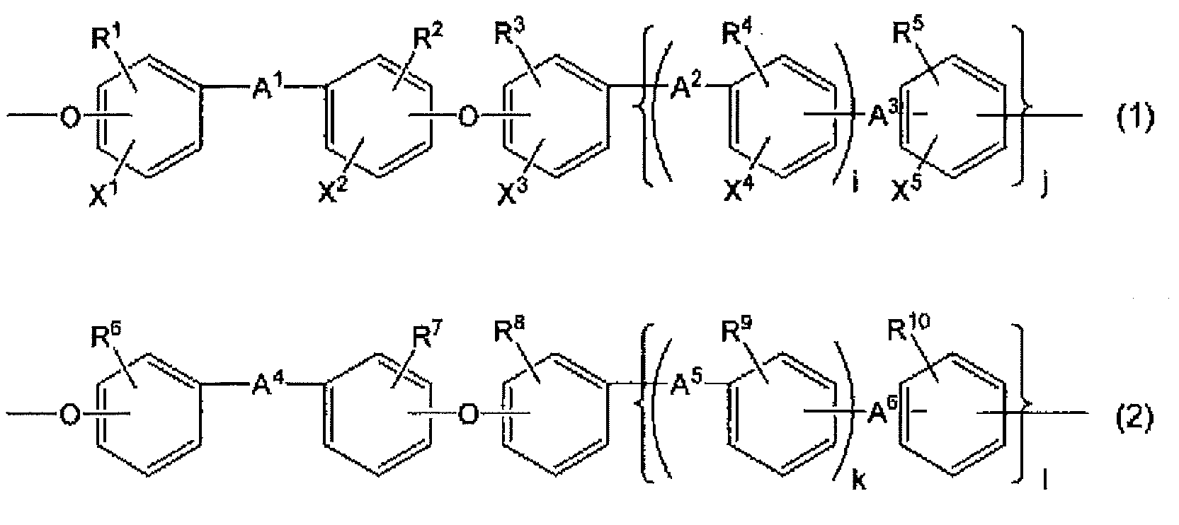
R1~R10は、それぞれ独立して、H、Cl、F、CF3またはCmH2m+1(mは1~10の整数を示す。)であり、
R1~R10の少なくとも1つはCmH2m+1(mは1~10の整数を示す。)であり、
R1~R10は、それぞれ芳香環に2つ以上存在してもよく、1つの芳香環にCmH2m+1が2つ以上存在する場合には、各CmH2m+1は互いに同一であっても異なっていてもよい。
X1~X5は、それぞれ独立して、H、Cl、F、CF3またはプロトン酸基であり、
X1~X5の少なくとも1つはプロトン酸基であり、
X1~X5は、それぞれ芳香環に2つ以上存在してもよく、1つの芳香環にプロトン酸基が2つ以上存在する場合には、各プロトン酸基は互いに同一であっても異なっていてもよい。
X1~X5の少なくとも1つはプロトン酸基であり、
X1~X5は、それぞれ芳香環に2つ以上存在してもよく、1つの芳香環にプロトン酸基が2つ以上存在する場合には、各プロトン酸基は互いに同一であっても異なっていてもよい。
A1~A6は、それぞれ独立して、直接結合、-CH2-、-C(CH3)2-、-C(CF3)2-、-O-または-CO-である。
i,j,kおよびlは、それぞれ独立して、0または1を示す。]
[2]
前記構造単位(1)および前記構造単位(2)の合計量に対する前記構造単位(1)および前記構造単位(2)のモル分率をそれぞれpおよびqとすると、p/q=10/90~70/30である上記[1]に記載の正浸透膜。
[2]
前記構造単位(1)および前記構造単位(2)の合計量に対する前記構造単位(1)および前記構造単位(2)のモル分率をそれぞれpおよびqとすると、p/q=10/90~70/30である上記[1]に記載の正浸透膜。
[3]
前記プロトン酸基含有芳香族ポリエーテル樹脂の重量平均分子量が70,000以上である上記[1]または[2]に記載の正浸透膜。
前記プロトン酸基含有芳香族ポリエーテル樹脂の重量平均分子量が70,000以上である上記[1]または[2]に記載の正浸透膜。
[4]
前記半透膜の厚さが3μm以下である上記[1]~[3]のいずれかに記載の正浸透膜。
前記半透膜の厚さが3μm以下である上記[1]~[3]のいずれかに記載の正浸透膜。
[5]
引張破断強度および伸び率が、それぞれ40MPa以上および40%以上である、上記[1]~[4]のいずれかに記載の正浸透膜。
引張破断強度および伸び率が、それぞれ40MPa以上および40%以上である、上記[1]~[4]のいずれかに記載の正浸透膜。
[6]
前記半透膜と、その両面に配置された前記多孔質基材とを有する上記[1]~[5]のいずれかに記載の正浸透膜。
前記半透膜と、その両面に配置された前記多孔質基材とを有する上記[1]~[5]のいずれかに記載の正浸透膜。
[7]
上記[1]~[6]のいずれかに記載の正浸透膜およびスペーサーを備える正浸透膜エレメント。
上記[1]~[6]のいずれかに記載の正浸透膜およびスペーサーを備える正浸透膜エレメント。
[8]
上記[7]に記載の正浸透膜エレメントを容器に収容してなる正浸透膜モジュール。
上記[7]に記載の正浸透膜エレメントを容器に収容してなる正浸透膜モジュール。
[9]
上記[8]に記載の正浸透膜モジュール、および前記正浸透膜モジュールが備える前記正浸透膜の一方の面にフィード溶液を、もう一方の面に前記フィード溶液よりも高濃度のドロー溶液を流すための駆動ポンプを有し、前記フィード溶液に含まれる水を、前記正浸透膜を通して前記ドロー溶液へ移動させることのできるように構成されたシステム。
上記[8]に記載の正浸透膜モジュール、および前記正浸透膜モジュールが備える前記正浸透膜の一方の面にフィード溶液を、もう一方の面に前記フィード溶液よりも高濃度のドロー溶液を流すための駆動ポンプを有し、前記フィード溶液に含まれる水を、前記正浸透膜を通して前記ドロー溶液へ移動させることのできるように構成されたシステム。
本発明によれば、高いろ過機能、塩阻止率を維持しつつ、高い水透過速度性能を発現できる正浸透膜が提供される。
以下、本発明について具体的に説明する。
本発明に係る正浸透膜は、半透膜と、その少なくとも一方の面に配置された多孔質基材とを備えている。
[半透膜]
(プロトン酸基含有芳香族ポリエーテル樹脂)
前記半透膜は、プロトン酸基含有芳香族ポリエーテル樹脂を含んでなる。プロトン酸基含有芳香族ポリエーテル樹脂は下式(1)で表される構造単位および下式(2)で表される構造単位(2)を含んでいる。
(プロトン酸基含有芳香族ポリエーテル樹脂)
前記半透膜は、プロトン酸基含有芳香族ポリエーテル樹脂を含んでなる。プロトン酸基含有芳香族ポリエーテル樹脂は下式(1)で表される構造単位および下式(2)で表される構造単位(2)を含んでいる。

i,j,kおよびlは、それぞれ独立して、0または1を示す。
R1~R10は、それぞれ独立して、H、Cl、F、CF3またはCmH2m+1(mは1~10の整数を示す。)であり、CmH2m+1としては、たとえばメチル基、エチル基、プロピル基、ブチル基、ペンチル基、ヘキシル基が挙げられる。
R1~R10の少なくとも1つはCmH2m+1(mは1~10の整数を示す。)である。具体的には、i,j,kおよびlならびにR1~R10は、前記構造単位(1)および/または前記構造単位(2)が、CmH2m+1で表される基を少なくとも1つ有するように選択される。すなわち、i,j,kおよびlがすべて1の場合には、R1~R10の少なくとも1つがCmH2m+1であるが、たとえばi=0、j=1、k=0かつl=1の場合には、R1~R3、R5~R8およびR10の少なくとも1つがCmH2m+1である。
R1~R10は、それぞれ芳香環に2つ以上存在してもよく、1つの芳香環にCmH2m+1が2つ以上存在する場合には、各CmH2m+1は互いに同一であっても異なっていてもよい。
X1~X5は、それぞれ独立して、H、Cl、F、CF3またはプロトン酸基である。
X1~X5の少なくとも1つはプロトン酸基である。具体的には、iおよびjならびにX1~X5は、前記構造単位(1)が、プロトン酸基を少なくとも1つ有するように選択される。すなわち、i=1かつj=1の場合にはX1~X5の少なくとも1つがプロトン酸基であるが、j=0の場合にはX1~X3の少なくとも1つがプロトン酸基であり、i=0かつj=1の場合にはX1~X3およびX5の少なくとも1つがプロトン酸基である。
X1~X5は、それぞれ芳香環に2つ以上存在してもよく、1つの芳香環にプロトン酸基が2つ以上存在する場合には、各プロトン酸基は互いに同一であっても異なっていてもよい。
A1~A6は、それぞれ独立して、直接結合、-CH2-、-C(CH3)2-、-C(CF3)2-、-O-または-CO-であり、A1~A6の少なくとも1つは-CO-である。
式(1)および(2)の両端の線は、隣り合う構造単位との結合を示す。
本発明において、プロトン酸基とは、プロトンを放出しやすい官能基またはその水素原子がNaまたはKで置換されたものを意味し、その例としては、スルホン酸基(-SO3H)、カルボン酸基(-COOH)、ホスホン酸基(-PO3H2)、アルキルスルホン酸基(-(CH2)nSO3H)、アルキルカルボン酸基(-(CH2)nCOOH)、アルキルホスホン酸基(-(CH2)nPO3H2)、ヒドロキシフェニル基(-C6H4OH)およびこれらの末端水素原子がNaまたはKで置換されたものが挙げられる。前記プロトン酸基としては、-CnH2n-SO3Y(nは0~10の整数、YはH、NaまたはKである)が好ましい。
前記構造単位(1)の例としては、下式(1-1)または下式(1-2)で表される構造単位が挙げられ、これらの構造においてはA1が-CO-であることが好ましく、
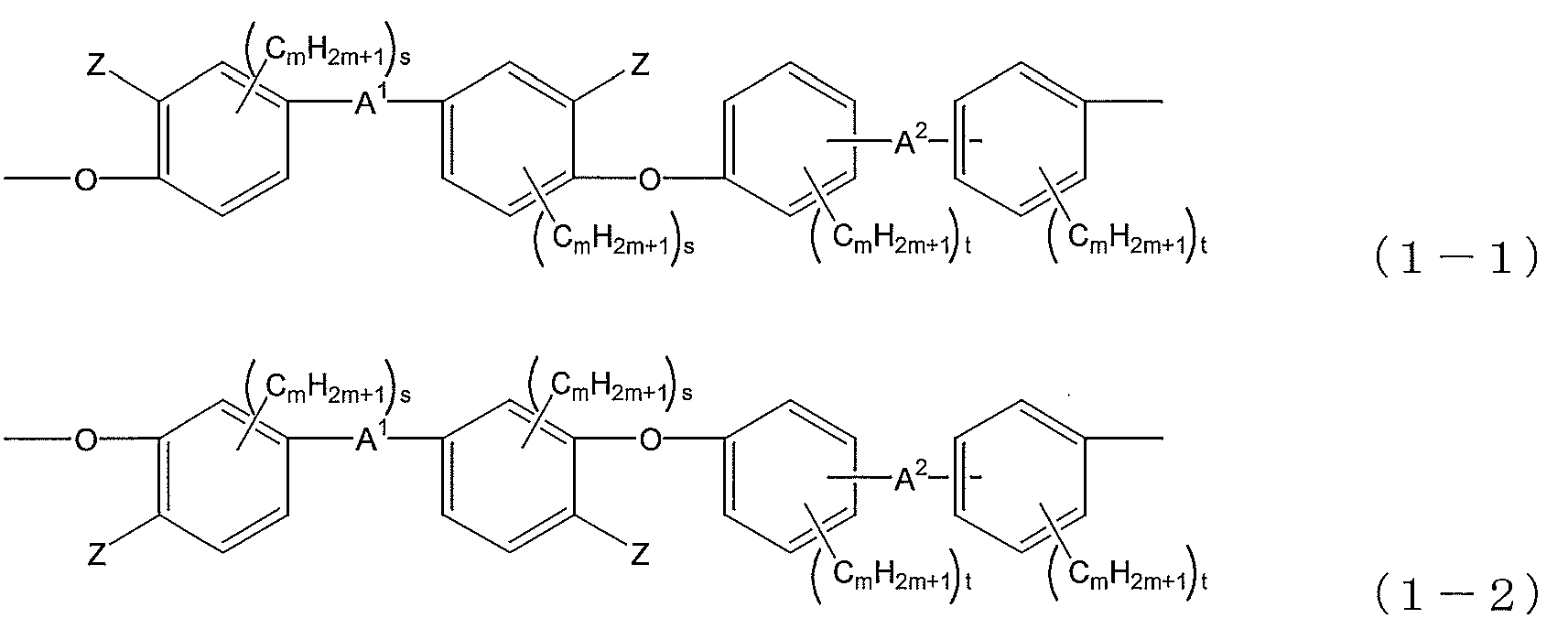
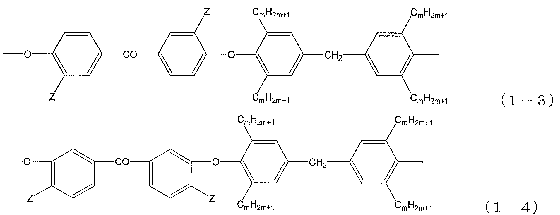
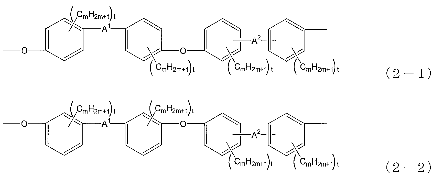
また、構造単位(2)の例としては、下式(2-1)または下式(2-2)で表される構造単位が挙げられ、

前記構造単位(1)および前記構造単位(2)の合計量に対する前記構造単位(1)および前記構造単位(2)のモル分率をそれぞれpおよびqとすると、水透過性の高い半透膜を形成できることから、p/qは好ましくは10/90以上、より好ましくは20/80以上、さらに好ましくは30/70以上である。である。また、塩阻止率が高く、かつゲル化しない半透膜を形成できることから、p/qは好ましくは90/10以下、より好ましくは70/30以下、さらに好ましくは60/40以下である。
前記プロトン酸基含有芳香族ポリエーテル樹脂は、さらに、後述する多官能化合物に由来する構造単位を含んでいてもよい。
前記プロトン酸基含有芳香族ポリエーテル樹脂は、架橋体であってもよく、非架橋体であってもよい。
前記プロトン酸基含有芳香族ポリエーテル樹脂の、後述する実施例で採用された方法により測定される重量平均分子量(Mw)は、好ましくは70,000以上、より好ましくは80,000以上、さらに好ましくは90,000以上である。分子量が上記範囲にあると、得られる半透膜は機械特性が高く、製膜時や使用時に破れ難い。また、前記重量平均分子量は、ゲル発生率の観点からは180,000以下である。
前記重量平均分子量は、前記プロトン酸基含有芳香族ポリエーテル樹脂を製造する際に、原料モノマーのモル比や、末端封止剤の量を調整することにより制御することができる。
前記プロトン酸基含有芳香族ポリエーテル樹脂のプロトン酸基当量、すなわちプロトン酸基1モル当たりのプロトン酸基含有芳香族ポリエーテル樹脂の質量は、水やメタノールに溶解せず、膨潤が抑えられた、電解質の膜透過量が小さい半透膜が得られることから、好ましくは200g/mol以上である。また、水の透過流束が大きく経済性の高い半透膜が得られることから、好ましくは5000g/mol以下、より好ましくは1000g/mol以下である。
(プロトン酸基含有芳香族ポリエーテル樹脂の製造方法)
前記プロトン酸基含有芳香族ポリエーテル樹脂は、従来公知の方法(たとえばWO2003/33566に記載された方法)に従い、芳香環を有する単量体の縮合によって得ることができる。たとえば、下式(1a)および(2a)
前記プロトン酸基含有芳香族ポリエーテル樹脂は、従来公知の方法(たとえばWO2003/33566に記載された方法)に従い、芳香環を有する単量体の縮合によって得ることができる。たとえば、下式(1a)および(2a)


式中、Yはハロゲン原子であり、他の各符号の意味は、上記式(1)および(2)の中で使用された同じ符号の意味と同一である。前記ハロゲン原子としては、好ましくはフッ素および塩素が挙げられる。
縮合にはK2CO3等の塩基性触媒を用いることが好ましい。
上記式(1a)で表される単量体(ただし、X1~X2の少なくとも1つがプロトン酸基であるもの。)としては、たとえば5,5'-カルボニルビス(2-フルオロベンゼンスルホン酸ナトリウム)、5,5'-カルボニルビス(2-クロロベンゼンスルホン酸ナトリウム)等のプロトン酸基含有芳香族ジハライド化合物が挙げられる。
上記式(2a)で表される単量体としては、たとえば、
4,4'-ジフルオロベンゾフェノン、3,3'-ジフルオロベンゾフェノン、4,4'-ジクロロベンゾフェノン、3,3'-ジクロロベンゾフェノン、4,4'-ジフルオロビフェニル、4,4'-ジフルオロジフェニルメタン、4,4'-ジクロロジフェニルメタン、4,4'-ジフルオロジフェニルエーテル等の芳香族ジハライド化合物;および
3,3'-ジメチル-4,4'-ジフルオロベンゾフェノン、3,3'-ジエチル-4,4'-ジフルオロベンゾフェノン、3,3',5,5'-テトラメチル-4,4'-ジフルオロベンゾフェノン、3,3'-ジメチル-4,4'-ジクロロベンゾフェノン、3,3',4,4'-テトラメチル-5,5'-ジクロロベンゾフェノン等のアルキル基含有芳香族ジハライド化合物
が挙げられる。
4,4'-ジフルオロベンゾフェノン、3,3'-ジフルオロベンゾフェノン、4,4'-ジクロロベンゾフェノン、3,3'-ジクロロベンゾフェノン、4,4'-ジフルオロビフェニル、4,4'-ジフルオロジフェニルメタン、4,4'-ジクロロジフェニルメタン、4,4'-ジフルオロジフェニルエーテル等の芳香族ジハライド化合物;および
3,3'-ジメチル-4,4'-ジフルオロベンゾフェノン、3,3'-ジエチル-4,4'-ジフルオロベンゾフェノン、3,3',5,5'-テトラメチル-4,4'-ジフルオロベンゾフェノン、3,3'-ジメチル-4,4'-ジクロロベンゾフェノン、3,3',4,4'-テトラメチル-5,5'-ジクロロベンゾフェノン等のアルキル基含有芳香族ジハライド化合物
が挙げられる。
上記式(2b)で表される単量体(または、上記式(1b)で表される単量体(ただし、X3~X5がすべて水素原子であるもの。))としては、たとえば、
4,4'-ジヒドロキシビフェニル、4,4'-ジヒドロキシジフェニルメタン、4,4'-ジヒドロキシジフェニルエーテル、4,4'-ジヒドロキシベンゾフェノン、2,2-ビス(4-ヒドロキシフェニル)プロパン、1,1,1,3,3,3-ヘキサフルオロ-2,2-ビス(4-ヒドロキシフェニル)プロパン、1,4-ビス(4-ヒドロキシフェニル)ベンゼン、α,α'-ビス(4-ヒドロキシフェニル)-1,4-ジメチルベンゼン、α,α'-ビス(4-ヒドロキシフェニル)-1,4-ジイソプロピルベンゼン、α,α'-ビス(4-ヒドロキシフェニル)-1,3-ジイソプロピルベンゼン、1,4-ビス(4-ヒドロキシベンゾイル)ベンゼン、3,3'-ジフルオロ-4,4'-ジヒドロキシビフェニル等の芳香族ジヒドロキシ化合物;および
3,3'-ジメチル-4,4'-ジヒドロキシビフェニル、3,3',5,5'-テトラメチル-4,4'-ジヒドロキシビフェニル、3,3'-ジメチル-4,4'-ジヒドロキシジフェニルメタン、3,3',5,5'-テトラメチル-4,4'-ジヒドロキシジフェニルメタン(別名:ビス(3,5-ジメチル-4-ヒドロキシフェニル)メタン)、3,3',5,5'-テトラエチル-4,4'-ジヒドロキシジフェニルメタン、3,3'-ジメチル-4,4'-ジヒドロキシジフェニルエーテル、3,3',5,5'-テトラメチル-4,4'-ジヒドロキシジフェニルエーテル、2,2-ビス(3-メチル-4-ヒドロキシフェニル)プロパン、2,2-ビス(3-エチル-4-ヒドロキシフェニル)プロパン、2,2-ビス(3,5-ジメチル-4-ヒドロキシフェニル)プロパン、α,α'-ビス(3-メチル-4-ヒドロキシフェニル)-1,4-ジイソプロピルベンゼン、α,α'-ビス(3,5-ジメチル-4-ヒドロキシフェニル)-1,4-ジイソプロピルベンゼン、α,α'-ビス(3-メチル-4-ヒドロキシフェニル)-1,3-ジイソプロピルベンゼン、α,α'-ビス(3,5-ジメチル-4-ヒドロキシフェニル)-1,3-ジイソプロピルベンゼン等のアルキル基含有芳香族ジヒドロキシ化合物
が挙げられる。
4,4'-ジヒドロキシビフェニル、4,4'-ジヒドロキシジフェニルメタン、4,4'-ジヒドロキシジフェニルエーテル、4,4'-ジヒドロキシベンゾフェノン、2,2-ビス(4-ヒドロキシフェニル)プロパン、1,1,1,3,3,3-ヘキサフルオロ-2,2-ビス(4-ヒドロキシフェニル)プロパン、1,4-ビス(4-ヒドロキシフェニル)ベンゼン、α,α'-ビス(4-ヒドロキシフェニル)-1,4-ジメチルベンゼン、α,α'-ビス(4-ヒドロキシフェニル)-1,4-ジイソプロピルベンゼン、α,α'-ビス(4-ヒドロキシフェニル)-1,3-ジイソプロピルベンゼン、1,4-ビス(4-ヒドロキシベンゾイル)ベンゼン、3,3'-ジフルオロ-4,4'-ジヒドロキシビフェニル等の芳香族ジヒドロキシ化合物;および
3,3'-ジメチル-4,4'-ジヒドロキシビフェニル、3,3',5,5'-テトラメチル-4,4'-ジヒドロキシビフェニル、3,3'-ジメチル-4,4'-ジヒドロキシジフェニルメタン、3,3',5,5'-テトラメチル-4,4'-ジヒドロキシジフェニルメタン(別名:ビス(3,5-ジメチル-4-ヒドロキシフェニル)メタン)、3,3',5,5'-テトラエチル-4,4'-ジヒドロキシジフェニルメタン、3,3'-ジメチル-4,4'-ジヒドロキシジフェニルエーテル、3,3',5,5'-テトラメチル-4,4'-ジヒドロキシジフェニルエーテル、2,2-ビス(3-メチル-4-ヒドロキシフェニル)プロパン、2,2-ビス(3-エチル-4-ヒドロキシフェニル)プロパン、2,2-ビス(3,5-ジメチル-4-ヒドロキシフェニル)プロパン、α,α'-ビス(3-メチル-4-ヒドロキシフェニル)-1,4-ジイソプロピルベンゼン、α,α'-ビス(3,5-ジメチル-4-ヒドロキシフェニル)-1,4-ジイソプロピルベンゼン、α,α'-ビス(3-メチル-4-ヒドロキシフェニル)-1,3-ジイソプロピルベンゼン、α,α'-ビス(3,5-ジメチル-4-ヒドロキシフェニル)-1,3-ジイソプロピルベンゼン等のアルキル基含有芳香族ジヒドロキシ化合物
が挙げられる。
前記プロトン酸基含有芳香族ポリエーテル樹脂の溶剤溶解性が損なわれない範囲で、前記単量体と共に多官能化合物を共重合してもよい。多官能化合物を共重合することにより、前記プロトン酸基含有芳香族ポリエーテル樹脂は微架橋構造を取ることができる。多官能化合物としては、1分子中に3個以上の水酸基を有するもの、例えば(2,4-ジヒドロキシフェニル)(4-ヒドロキシフェニル)メタノン、4-[1-(4-ヒドロキシフェニル)-1-メチルエチル]-1,3-ベンゼンジオール、4-[(2,3,5-トリメチル-4-ヒドロキシフェニル)メチル]-1,3-ベンゼンジオール、4-[(4-ヒドロキシフェニル)メチル]-1,2,3-ベンゼントリオール、(4-ヒドロキシフェニル)(2,3,4-トリヒドロキシフェニル)メタノン、4-[(3,5-ジメチル-4-ヒドロキシフェニル)メチル]-1,2,3-ベンゼントリオール、4-[(2,3,5-トリメチル-4-ヒドロキシフェニル)メチル]-1,2,3-ベンゼントリオール、4,4'-[1,4-フェニレンビス(1-メチルエチリデン)]ビス[ベンゼン-1,2-ジオール]、5,5'-[1,4-フェニレンビス(1-メチルエチリデン)]ビス[ベンゼン-1,2,3-トリオール]、α,α,α'-トリス(4-ヒドロキシフェニル)-1-エチル-4-イソプロピルベンゼン、フロログルシン、ピロガロール等が挙げられる。
これらの共重合量は、前記プロトン酸基含有芳香族ポリエーテル樹脂の溶剤溶解性の低下、前記樹脂の製膜時の流動性の低下、半透膜の伸び率の低下を防止する観点から、好ましくは0~8mol%/全OH当量(すなわち、上記式(1b)の単量体、式(2b)の単量体および多官能単量体が有するOH基の全量(100mol%)のうち、0~8mol%が多官能単量体由来のOH基である。)、さらに好ましくは0~5mol%/全OH当量である。
(プロトン酸基含有芳香族ポリエーテル樹脂のワニス)
前記プロトン酸基含有芳香族ポリエーテル樹脂は、その分子構造が基本的には直鎖状であり、前記多官能化合物に由来する架橋構造を有していてもその量は僅かであることから、溶剤溶解性に優れる。したがって、該樹脂を溶剤に溶解したワニスの形態とすることができる。
前記プロトン酸基含有芳香族ポリエーテル樹脂は、その分子構造が基本的には直鎖状であり、前記多官能化合物に由来する架橋構造を有していてもその量は僅かであることから、溶剤溶解性に優れる。したがって、該樹脂を溶剤に溶解したワニスの形態とすることができる。
溶剤の例としては、特に制限はなく、水、メタノール、エタノール、1-プロパノール、2-プロパノール、ブタノールなどのアルコール類、トルエン、キシレンなどの炭化水素類、塩化メチル、塩化メチレンなどのハロゲン化炭化水素類、ジクロロエチルエーテル、1,4-ジオキサン、テトラヒドロフランなどのエーテル類、酢酸メチル、酢酸エチルなどの脂肪酸エステル類、アセトン、メチルエチルケトンなどのケトン類、2-メトキシエタノール、2-エトキシエタノールなどのセロソルブ類、N,N-ジメチルアセトアミド、N-メチル-2-ピロリドン、ジメチルスルホキシド、炭酸ジメチルなどの非プロトン性極性溶剤類が挙げられる。これらは1種単独で、または2種以上を混合して使用できる。中でも、低級アルコール類(メタノール、エタノール、1-プロパノール、2-プロパノール、t-ブチルアルコールなど)、テトラヒドロフラン、N-メチル-2-ピロリドンなどは、水溶性のため好ましく、更にこれらと水との混合溶媒も好ましい。ワニス中の樹脂濃度は、ワニスの使用方法により選択できるが、好ましくは1重量%以上80重量%以下である。
(半透膜)
前記半透膜は、前記プロトン酸基含有芳香族ポリエーテル樹脂からなる。
前記半透膜は、前記プロトン酸基含有芳香族ポリエーテル樹脂からなる。
前記半透膜は、実質的に前記プロトン酸基含有芳香族ポリエーテル樹脂のみからなるが、他の成分を本発明の効果を損なわない程度に少量(たとえば、1質量%以下、または0.1質量%以下)含んでいてもよい。
前記半透膜の厚さは、通常、0.01~3.0μm、好ましくは0.01~1.5μmである。前記厚さがこの範囲内にある半透膜を用いた正浸透膜は、十分な膜強度を有し、かつ実用上十分大きな水の透過流束を示す。前記半透膜の厚さは、半透膜の製造条件、例えばプレス成形時の温度や圧力、キャスト時のワニス濃度や塗布厚などにより制御することができる。
前記半透膜の引張弾性率は、好ましくは0.8~2.0GPa、更に好ましくは1.2~1.6GPaである。前記半透膜の引張破断強度は、好ましくは40MPa以上であり、その上限はたとえば100MPaである。また、前記半透膜の伸び率は、好ましくは40%以上であり、その上限はたとえば200%である。これらの引張弾性率、引張破断強度および伸び率は、下記の条件で測定した場合のものである。
<引張弾性率、引張破断強度および伸び率の測定条件>
長さ×幅×厚さ=100mm×10mm×5μmの試験片を作製し、引張試験機を用いて速度50mm/分で引っ張り、試験片が切断(破断)したときの強度(引張荷重値を試験片の断面積で除した値)、および伸び率を求める。伸び率は次の式によって算出する。
長さ×幅×厚さ=100mm×10mm×5μmの試験片を作製し、引張試験機を用いて速度50mm/分で引っ張り、試験片が切断(破断)したときの強度(引張荷重値を試験片の断面積で除した値)、および伸び率を求める。伸び率は次の式によって算出する。
伸び率(%)=100×(L-L0)/L0
(L0:試験前の試験片長さ L:破断時の試験片長さ)
また、引張弾性率は、破断時の加重を試験片の断面積および破断時の歪量、すなわち(L-L0)/L0で除した値とする。
(L0:試験前の試験片長さ L:破断時の試験片長さ)
また、引張弾性率は、破断時の加重を試験片の断面積および破断時の歪量、すなわち(L-L0)/L0で除した値とする。
前記引張破断強度および前記伸び率は、たとえば、前記プロトン酸基含有芳香族ポリエーテル樹脂の分子量を高めることによって大きくすることができる。
前記半透膜のジメチルスルホキシド(以下「DMSO」ともいう。)および水に対する溶解性は、各々以下の質量減少率によって評価することができる。前記質量減少率は、好ましくは2質量%未満、より好ましくは1.0質量%以下、特に好ましくは0.5質量%以下である。
<質量減少率の測定方法>
半透膜を、窒素雰囲気下、150℃で4時間静置して乾燥させた後、秤量する。半透膜を、DMSOまたは水に浸し、25℃で24時間静置する。半透膜を、DMSOまたは水取り出し、窒素雰囲気下、150℃で4時間静置して乾燥させた後、秤量する。半透膜の浸漬前後の質量に基づき、下記式から質量減少率を算出する。
半透膜を、窒素雰囲気下、150℃で4時間静置して乾燥させた後、秤量する。半透膜を、DMSOまたは水に浸し、25℃で24時間静置する。半透膜を、DMSOまたは水取り出し、窒素雰囲気下、150℃で4時間静置して乾燥させた後、秤量する。半透膜の浸漬前後の質量に基づき、下記式から質量減少率を算出する。
質量減少率=(半透膜の浸漬前の質量-半透膜の浸漬後の質量)/半透膜の浸漬前の質量×100
前記溶解量は、たとえば前記プロトン酸基含有芳香族ポリエーテル樹脂を架橋することにより小さくでき、したがって前記プロトン酸基当量が小さくても前記溶解量を上記の範囲とすることができる。
前記溶解量は、たとえば前記プロトン酸基含有芳香族ポリエーテル樹脂を架橋することにより小さくでき、したがって前記プロトン酸基当量が小さくても前記溶解量を上記の範囲とすることができる。
(半透膜の製造方法)
前記半透膜は、前記プロトン酸基含有芳香族ポリエーテル樹脂から、自立膜として製造することができる。
前記半透膜は、前記プロトン酸基含有芳香族ポリエーテル樹脂から、自立膜として製造することができる。
前記半透膜は、前記プロトン酸基含有芳香族ポリエーテル樹脂をプレス成形や押し出し成形することにより、容易に製造できる。また、前記プロトン酸基含有芳香族ポリエーテル樹脂の膜に、延伸処理などを施してもよい。
前記半透膜は、前述のワニスからキャスト法により製造することもできる。すなわち、前記ワニスを支持体上に塗布し、溶剤を揮発除去することにより半透膜を得ることができる。さらに、半透膜を支持体から剥離して自立膜としてもよい。
前記半透膜中にキャスト時の有機溶剤などが残存している場合には、前記半透膜は機械強度が低下し破損しやすくなる恐れがある。そのため、キャスト法により製造された前記半透膜には、十分な乾燥、および/または水、硫酸水溶液、塩酸などでの洗浄を施すことが好ましい。
なお、前記半透膜の製造に用いる前記プロトン酸基含有芳香族ポリエーテル樹脂が有する前記プロトン酸基が、プロトンを放出し易い官能基において水素原子がNaまたはKで置換されたものである場合に、該プロトン酸基含有芳香族ポリエーテル樹脂の膜を形成し、次いでこの膜を塩酸、硫酸水溶液などと接触させることにより前記プロトン酸基が有するNaまたはKを水素原子に置換してもよい。
[多孔質基材]
前記多孔質基材の通気度は、100~400cm3/cm2/sである。この通気度はJIS L1096に記載のA法(フラジール形法)に基づき、以下のように測定される。
前記多孔質基材の通気度は、100~400cm3/cm2/sである。この通気度はJIS L1096に記載のA法(フラジール形法)に基づき、以下のように測定される。
20cm×20cmの試験片を試験機に取り付け、傾斜形気圧計が125Paの圧力になるように吸い込みファン及び空気孔を調整し、垂直形気圧計の示す圧力を測定する。測定した圧力と空気孔の種類から試験機に附属の換算表によって試験片を通過する空気量を求める。
また、前記多孔質基材の厚さは、通常50~700μm、好ましくは80~600μm、更に好ましくは100~500μmである。
本発明の正浸透膜は、このように高い通気度を有しかつ薄い多孔質基材が用いられるため、正浸透膜を使用する際に多孔質基材の内部に生じる濃度分極が抑制され、かつ水が正浸透膜を透過する時の流体抵抗を小さくでき、結果として正浸透膜における水の透過流束を大きくすることができる、と考えられる。前記多孔質基材の通気度および厚さは、常法により制御することができる。
多孔質基材を構成する好ましい材質としては、合成樹脂および天然繊維を挙げることができる。
合成樹脂としては、熱可塑性樹脂および熱硬化性樹脂が挙げられ、熱可塑性樹脂が好ましい。熱可塑性樹脂の具体例としては、オレフィン系重合体、ポリエステル樹脂、ポリアミド樹脂、ポリ塩化ビニル、(メタ)アクリル系樹脂を挙げることができる。中でも、オレフィン系重合体及びポリエステル樹脂が好ましく、オレフィン系重合体が特に好ましい。
オレフィン系重合体としては、具体的には、α-オレフィンの単独重合体もしくは共重合体、またはα-オレフィンと他のモノマーとの共重合体である。α-オレフィンとしては、エチレン、プロピレン、1-ブテンなどの炭素数2~8のα-オレフィンが挙げられる。オレフィン系重合体には、ポリプロピレン、ポリエチレン、ポリ1-ブテン、ポリ4-メチル-1-ペンテン、エチレン・プロピレン共重合体、エチレン・1-ブテン共重合体、エチレン・4-メチル-1-ペンテン共重合体、プロピレン・1-ブテン共重合体、4-メチル-1-ペンテン・1-デセン共重合体などのポリオレフィン樹脂、エチレン・ビニルアルコール共重合体などのα-オレフィンと他のモノマーとの共重合体が含まれる。
ポリエステル樹脂としては、ポリエチレンテレフタレート、ポリブチレンテレフタレート及びポリエチレンナフタレートなどが挙げられる。ポリアミド樹脂としては、例えば、ナイロン6、ナイロン66が挙げられる。
天然繊維としては、綿、麻などの植物繊維、絹、羊毛などの動物繊維が挙げられる。中でも、綿および絹が好ましい。
前記多孔質基材としては、織布、不織布、編布などの布質基材、発泡シートなどが挙げられ、中でも布質基材が好ましく、織布および不織布がさらに好ましく、不織布が特に好ましい。
不織布としては、スパンボンド法による長繊維不織布、メルトブローン法による短繊維不織布、フラッシュ紡糸不織布などの長繊維不織布、スパンレース不織布、エアレイド不織布、サーマルボンド不織布、ニードルパンチ不織布、ケミカルボンド不織布などを挙げることができるが、スパンボンド不織布及びメルトブローン不織布が好ましい。中でもスパンボンド不織布が好ましく、ポリエチレンテレフタレートまたはポリプロピレンのスパンボンド不織布が特に好ましい。
前記不織布は、構成する繊維を異なった樹脂による複合繊維とし、繊維外表面側に異なった樹脂を配した芯鞘型またはサイドバイサイド型複合繊維であってもよい。複合繊維の例としてポリエチレン/ポリプロピレンの芯鞘型またはサイドバイサイド型複合繊維が挙げられる。
前記不織布は、積層不織布であってもよい。積層不織布の例としては、スパンボンド不織布およびメルトブローン不織布を含む積層不織布が挙げられ、スパンボンド不織布とメルトブローン不織布とが積層されたもの(SM)、スパンボンド不織布とメルトブローン不織布とスパンボンド不織布とがこの順序で積層されたもの(SMS)などが挙げられる。
このような積層不織布を得るには、スパンボンド不織布とメルトブローン不織布とを積層し、両者を一体化して形成させる。一体化する方法の例としては、スパンボンド不織布とメルトブローン不織布を重ね合わせて加熱加圧する方法、ホットメルト接着剤、溶剤系接着剤等の接着剤によって両者を接着する方法、スパンボンド不織布の上にメルトブローン法により繊維を堆積させて熱融着する方法が挙げられる。
前記不織布は、不織布の間に微小孔を有する多孔性フィルムを挟んだ形態の積層不織布であってもよい。このような形態の積層不織布として、例えばポリプロピレン(PP)不織布と多孔性PPフィルムとPP不織布(SFS)とがこの順序で積層されたもの、PP不織布と多孔性PPフィルムとレーヨンPP不織布(SFR)とがこの順序で積層されたものなどを挙げることができる。
前記不織布の目付(積層不織布の場合には積層不織布としての目付)は、好ましくは10~80g/m2程度、より好ましくは20~40g/m2程度である。
[正浸透膜]
(正浸透膜)
本発明の正浸透膜は、前記半透膜と、その少なくとも一方の面に配置された前記多孔質基材とを備えており、高いろ過機能、塩阻止率を維持しつつ、高い水透過速度性能を実現できる。
(正浸透膜)
本発明の正浸透膜は、前記半透膜と、その少なくとも一方の面に配置された前記多孔質基材とを備えており、高いろ過機能、塩阻止率を維持しつつ、高い水透過速度性能を実現できる。
本発明に係る正浸透膜は、前記半透膜の両面に前記多孔質基材を備えていてもよい。この態様であれば、正浸透膜の強度がさらに向上する。
本発明に係る正浸透膜は、前記半透膜の両面または片面に前記多孔質基材以外の層を、半透膜/多孔質基材以外の層/多孔質基材の順序となるように含んでも良いが、良好な透過流束を得る面から多孔質基材以外の層を含まない方が好ましい。多孔質基材以外の層としてポリアミド層を含んでもよいが、その厚さは100μm以下が好ましい。
(正浸透膜の製造方法)
本発明の正浸透膜は、たとえば前記半透膜を自立膜として製造し、前記半透膜をその両面から2つの前記多孔質基材で挟むことによって製造することができる。
本発明の正浸透膜は、たとえば前記半透膜を自立膜として製造し、前記半透膜をその両面から2つの前記多孔質基材で挟むことによって製造することができる。
正浸透膜は、具体的には以下の手順で製造することができる。例えば、PET等からなる基材上に乾燥後の厚みが目的の厚さとなるよう前記プロトン酸基含有芳香族ポリエーテル樹脂の希薄溶液を塗布し、乾燥後、形成された膜を自立膜として剥がす。該自立膜を不織布等の2つの多孔質基材で挟み、正浸透膜を製造することができる。該正浸透膜の面積が大きい場合には、半透膜と多孔質基材との間隔を維持するために、両者を透過流速に影響を与えない程度に、接着剤を用いて接着してもよい。
また本発明の正浸透膜は、前記半透膜を自立膜として製造し、これを前記多孔質基材上に積層することによっても製造することができる。この際に両者を、接着剤を用いて貼り合わせてもよい。
上述のとおり、従来の複合半透膜ではスキン層(半透膜)の厚さの制御が困難であったが、本発明の製造方法によれば、上述した半透膜をまず自立膜として製造し、これを多孔質基材(不織布等)上に積層したり、2枚の多孔質基材(不織布等)で挟んだりして正浸透膜を製造するため、半透膜の厚さが制御され、かつ高い水透過性および高い塩阻止率を示す正浸透膜を、簡便に製造することができる。
[正浸透膜の用途]
本発明に係る正浸透膜エレメントは、上述した本発明に係る正浸透膜およびスペーサーを備えている。換言すると、本発明に係る正浸透膜エレメントは、正浸透膜およびスペーサーを備える従来の正浸透膜エレメントにおいて、正浸透膜として本発明に係る正浸透膜が使用されたものである。スペーサーとしては、正浸透膜エレメントに使用される従来公知のスペーサーを使用することができる。
本発明に係る正浸透膜エレメントは、上述した本発明に係る正浸透膜およびスペーサーを備えている。換言すると、本発明に係る正浸透膜エレメントは、正浸透膜およびスペーサーを備える従来の正浸透膜エレメントにおいて、正浸透膜として本発明に係る正浸透膜が使用されたものである。スペーサーとしては、正浸透膜エレメントに使用される従来公知のスペーサーを使用することができる。
本発明に係る正浸透膜モジュールは、本発明に係る正浸透膜エレメントを容器に収容してなる。換言すると、本発明に係る正浸透膜モジュールは、正浸透膜エレメントを容器に収容してなる従来の正浸透膜エレメントにおいて、正浸透膜エレメントとして本発明に係る正浸透膜エレメントが使用されたものである。容器としては、正浸透膜モジュールに使用される従来公知の容器を使用することができる。
本発明に係るシステムは、本発明に係る正浸透膜モジュール、および前記正浸透膜モジュールが備える本発明に係る正浸透膜の一方の面にフィード溶液を、もう一方の面に前記フィード溶液よりも高濃度のドロー溶液を流すための駆動ポンプを有し、前記フィード溶液に含まれる水を、前記正浸透膜を通して前記ドロー溶液へ移動させることのできるように構成されている。
以下、本発明を実施例によりさらに詳細に説明するが、本発明はこれにより何ら制限されるものではない。
本実施例および比較例で用いた略称の内容を示す。
(1)溶媒
DMSO :ジメチルスルホキシド
NMP :N-メチル-2-ピロリドン
DMF :N,N-ジメチルホルムアミド
(2)芳香族ポリエーテルの構成成分
DFBP :4,4'-ジフルオロベンゾフェノン
DSDFBP:5,5'-カルボニルビス(2-フルオロベンゼンスルホン酸ナトリウム)
DCDPS :4,4'-ジクロロジフェニルスルホン
DSDCDPS:5,5'-スルホニルビス(2-クロロベンゼンスルホン酸ナトリウム)
TMBPF : 3,3',5,5'-テトラメチル-4,4'-ジヒドロキシジフェニルメタン
TPPA : α,α,α'-トリス(4-ヒドロキシフェニル)-1-エチル-4-イソプロピルベンゼン
実施例中の各種試験の試験方法は次に示すとおりである。
DMSO :ジメチルスルホキシド
NMP :N-メチル-2-ピロリドン
DMF :N,N-ジメチルホルムアミド
(2)芳香族ポリエーテルの構成成分
DFBP :4,4'-ジフルオロベンゾフェノン
DSDFBP:5,5'-カルボニルビス(2-フルオロベンゼンスルホン酸ナトリウム)
DCDPS :4,4'-ジクロロジフェニルスルホン
DSDCDPS:5,5'-スルホニルビス(2-クロロベンゼンスルホン酸ナトリウム)
TMBPF : 3,3',5,5'-テトラメチル-4,4'-ジヒドロキシジフェニルメタン
TPPA : α,α,α'-トリス(4-ヒドロキシフェニル)-1-エチル-4-イソプロピルベンゼン
実施例中の各種試験の試験方法は次に示すとおりである。
・樹脂の評価
(i)重量平均分子量(Mw)
GPC(Gel Permeation Chromatography)法を用い、以下の条件により重量平均分子量(Mw)を求めた。
(i)重量平均分子量(Mw)
GPC(Gel Permeation Chromatography)法を用い、以下の条件により重量平均分子量(Mw)を求めた。
(1) 測定温度:40℃
(2) 展開溶媒:DMF
(3) 流量:1.0ml/分
(4) 注入量:500μl
(5) 検出器:UV検出器
(6) 分子量標準物質:標準ポリスチレン
・半透膜の評価
(ii)膜厚
日本分光社製分光光度計(エリプソメトリ)を用い膜厚を測定した。具体的には、屈折率nの膜に光がある角度(θ)で入射すると,膜の表面からの反射光Aと裏面からの反射光Bが干渉して,波打った干渉スペクトルが生じる。ある波長範囲(λ1~λ2)内における干渉スペクトルのピーク(山または谷)の数(Δm)を数えることで(1)式から膜厚(d)を算出した。
(2) 展開溶媒:DMF
(3) 流量:1.0ml/分
(4) 注入量:500μl
(5) 検出器:UV検出器
(6) 分子量標準物質:標準ポリスチレン
・半透膜の評価
(ii)膜厚
日本分光社製分光光度計(エリプソメトリ)を用い膜厚を測定した。具体的には、屈折率nの膜に光がある角度(θ)で入射すると,膜の表面からの反射光Aと裏面からの反射光Bが干渉して,波打った干渉スペクトルが生じる。ある波長範囲(λ1~λ2)内における干渉スペクトルのピーク(山または谷)の数(Δm)を数えることで(1)式から膜厚(d)を算出した。

引張試験機として島津製作所社製小型卓上引張試験機EZ-Sシリーズを用い、上述した方法で引張弾性率、引張破断強度および伸び率を測定した。
(iv)水への溶解性
半透膜を、窒素雰囲気下、150℃で4時間静置して乾燥させた後、秤量した。次いで、半透膜を水に浸漬し、25℃で24時間静置した。半透膜を、水から取り出し、窒素雰囲気下、150℃で4時間静置して乾燥させた後、秤量した。半透膜の浸漬前後の質量に基づき、下記式から質量減少率を算出した。
半透膜を、窒素雰囲気下、150℃で4時間静置して乾燥させた後、秤量した。次いで、半透膜を水に浸漬し、25℃で24時間静置した。半透膜を、水から取り出し、窒素雰囲気下、150℃で4時間静置して乾燥させた後、秤量した。半透膜の浸漬前後の質量に基づき、下記式から質量減少率を算出した。
質量減少率=(半透膜の浸漬前の質量-半透膜の浸漬後の質量)/半透膜の浸漬前の質量×100
表1における記号の意味は以下のとおりである。
表1における記号の意味は以下のとおりである。
○:質量減少率が1質量%未満
×:質量減少率が1質量%以上
・正浸透膜の評価
正浸透膜の分離性能の評価に用いた装置10の概略図を図1に示す。
×:質量減少率が1質量%以上
・正浸透膜の評価
正浸透膜の分離性能の評価に用いた装置10の概略図を図1に示す。
該装置10は、フィード溶液タンク1、流路2、ポンプ3、ドロー溶液タンク11、流路12、ポンプ13および評価用セル21を備えている。フィード溶液タンク1は天秤4上に設置され、ドロー溶液タンク11は電気伝導度計15を備えている。評価開始時において、フィード溶液タンク1には、フィード溶液FS(Feed Solution)として、50μS/cm以下の電気伝導度を持つMilli-Q水が500g蓄えられ、ドロー溶液タンク11には、ドロー溶液DS(Draw Solution)として、0.6MのNaCl水溶液が800g蓄えられている。フィード溶液タンク1中のフィード溶液は、ポンプ3の使用により0.6L/分の速度で流路2を流れ、ドロー溶液タンク11中のドロー溶液は、ポンプ13の使用により0.6L/分の速度で流路12を流れる。流路2を流れるフィード溶液と流路12を流れるドロー溶液とは、評価用セル21の内部で有効膜面積0.0042m2の正浸透膜22を介して接触しており、正浸透膜22を介してフィード溶液の一部はドロー溶液へと移動し、ドロー溶液中の塩(NaCl)の一部はフィード溶液へと移動(逆流)する。
(v)水透過流束(Jw)
天秤4により1分毎にフィード溶液の重量減少量を測定し、単位時間、正浸透膜の単位面積当たりの重量減少量を水透過流束(L/(m2・h))とした。循環開始後30~60分間の平均値を表2、6に示す。
天秤4により1分毎にフィード溶液の重量減少量を測定し、単位時間、正浸透膜の単位面積当たりの重量減少量を水透過流束(L/(m2・h))とした。循環開始後30~60分間の平均値を表2、6に示す。
(vi)塩阻止率
電気伝導度計15により1分毎にドロー溶液の電気伝導度の変化を測定し、これをドロー溶液のモル濃度の変化に換算し、単位時間、正浸透膜の単位面積当たりのモル濃度の変化を塩阻止率(Mol/(m2・h))とした。循環開始後30~60分間の平均値を表2、6に示す。
電気伝導度計15により1分毎にドロー溶液の電気伝導度の変化を測定し、これをドロー溶液のモル濃度の変化に換算し、単位時間、正浸透膜の単位面積当たりのモル濃度の変化を塩阻止率(Mol/(m2・h))とした。循環開始後30~60分間の平均値を表2、6に示す。
(単量体合成例1)
特開2014-533号公報の[0061]段落(合成例1)に記載の方法で、下式で表されるDSDFBPの白色結晶を得た。収量は155.2g(0.386mol、収率70%)であった。
特開2014-533号公報の[0061]段落(合成例1)に記載の方法で、下式で表されるDSDFBPの白色結晶を得た。収量は155.2g(0.386mol、収率70%)であった。
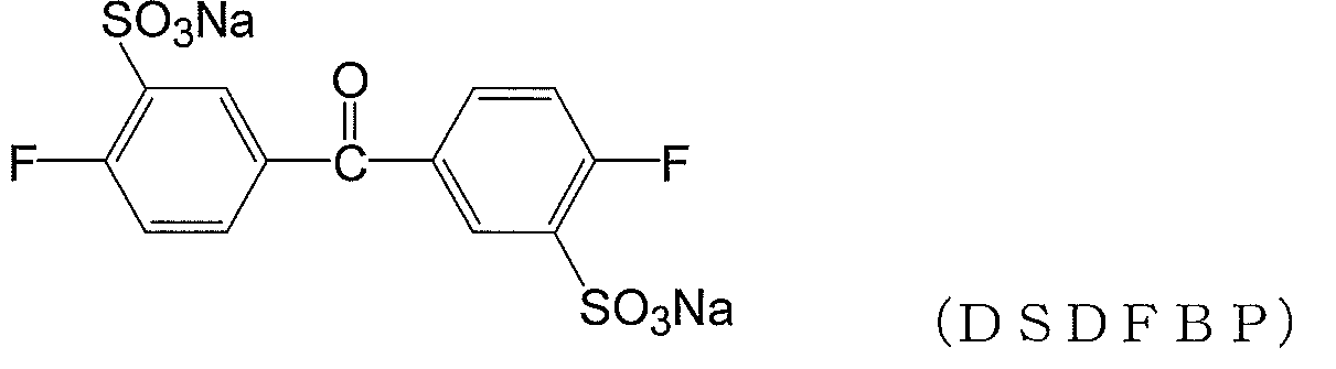
攪拌器、温度計および冷却管を装備した反応フラスコに、DCDPS(0.60mol)と、30%発煙硫酸180mlを装入した後、110℃で6時間反応した。これを、1.8kgの氷に排出した。次に、NaCl360gおよび水500mlを加え、加熱溶解した後放冷し一夜放置した。析出した結晶を濾過した後、水300ml、エタノール350mlを加えて加熱溶解後放冷し、再結晶を行った。析出した結晶を濾過後、再度水180mlとエタノール180mlで再結晶し、100℃で6時間および200℃で4時間乾燥して、下式で表されるDSDCDPSの白色結晶を得た。収量は95.5g(0.194mol、収率32%)であった。

窒素導入管、温度計、還流冷却器、及び撹拌装置を備えた5つ口反応器に、合成例1で得られたDSDFBP40.1g(0.095mol)、DFBP62.2g(0.285mol)、TMBPF97.4g(0.380mol)および炭酸カリウム65.7g(0.475mol)を秤取した。これにDMSO783.4gとトルエン261.1gを加え、窒素雰囲気下で撹拌し、130℃で12時間加熱し、生成する水を系外に除去した後、トルエンを留去した。
引き続き、160℃で12時間反応を行い、粘稠なポリマー溶液を得た。得られた溶液にトルエン570gを加えて希釈した後、メタノール2400gに排出し、析出したポリマー粉を濾過、洗浄後、150℃で4時間乾燥してポリエーテルケトン粉171.6g(収率95%)(樹脂1)を得た。
諸物性評価結果を表1に示す。
樹脂(1)は、前記構造単位(1)として


(樹脂合成例2)
樹脂の原料および溶媒を、DSDFBP48.1g(0.114mol)、DFBP58.0g(0.265mol)、TMBPF97.4g(0.380mol)および炭酸カリウム65.7g(0.475mol)、ならびにDMSO814.4gおよびトルエン271.5gとした他は実施例1と同様にしてポリマー粉175.2g(収率93%)(樹脂2)を得た。諸物性評価結果を表1に示す。
樹脂の原料および溶媒を、DSDFBP48.1g(0.114mol)、DFBP58.0g(0.265mol)、TMBPF97.4g(0.380mol)および炭酸カリウム65.7g(0.475mol)、ならびにDMSO814.4gおよびトルエン271.5gとした他は実施例1と同様にしてポリマー粉175.2g(収率93%)(樹脂2)を得た。諸物性評価結果を表1に示す。
(樹脂合成例3)
樹脂の原料および溶媒を、DSDFBP64.2g(0.152mol)、DFBP49.8g(0.228mol)、TMBPF97.4g(0.380mol)および炭酸カリウム65.7g(0.475mol)、ならびにDMSO845.4gおよびトルエン281.8gとした他は樹脂合成例1と同様にしてポリマー粉168.7g(収率86%)(樹脂3)を得た。諸物性評価結果を表1に示す。
樹脂の原料および溶媒を、DSDFBP64.2g(0.152mol)、DFBP49.8g(0.228mol)、TMBPF97.4g(0.380mol)および炭酸カリウム65.7g(0.475mol)、ならびにDMSO845.4gおよびトルエン281.8gとした他は樹脂合成例1と同様にしてポリマー粉168.7g(収率86%)(樹脂3)を得た。諸物性評価結果を表1に示す。
(樹脂合成例4)
樹脂の原料および溶媒を、DSDFBP80.2g(0.190mol)、DFBP41.5g(0.190mol)、TMBPF97.4g(0.380mol)および炭酸カリウム65.7g(0.475mol)、ならびにDMSO876.4gおよびトルエン292.1gとした他は樹脂合成例1と同様にしてポリマー粉174.6g(収率86%)(樹脂4)を得た。諸物性評価結果を表1に示す。
樹脂の原料および溶媒を、DSDFBP80.2g(0.190mol)、DFBP41.5g(0.190mol)、TMBPF97.4g(0.380mol)および炭酸カリウム65.7g(0.475mol)、ならびにDMSO876.4gおよびトルエン292.1gとした他は樹脂合成例1と同様にしてポリマー粉174.6g(収率86%)(樹脂4)を得た。諸物性評価結果を表1に示す。
(樹脂合成例5)
樹脂の原料および溶媒を、DSDFBP96.3g(0.228mol)、DFBP33.2g(0.152mol)、TMBPF97.4g(0.380mol)および炭酸カリウム65.7g(0.475mol)、ならびにDMSO907.5gおよびトルエン302.5gとした他は樹脂合成例1と同様にしてポリマー粉173.6g(収率82%)(樹脂5)を得た。諸物性評価結果を表1に示す。
樹脂の原料および溶媒を、DSDFBP96.3g(0.228mol)、DFBP33.2g(0.152mol)、TMBPF97.4g(0.380mol)および炭酸カリウム65.7g(0.475mol)、ならびにDMSO907.5gおよびトルエン302.5gとした他は樹脂合成例1と同様にしてポリマー粉173.6g(収率82%)(樹脂5)を得た。諸物性評価結果を表1に示す。
(樹脂合成例6)
樹脂の原料および溶媒を、DSDFBP160.5g(0.380mol)、TMBPF97.4g(0.380mol)および炭酸カリウム65.7g(0.475mol)、ならびにDMSO1031.5gおよびトルエン343.8gとした他は樹脂合成例1と同様にしてポリマー粉165.0g(収率68%)(樹脂6)を得た。諸物性評価結果を表1に示す。
樹脂の原料および溶媒を、DSDFBP160.5g(0.380mol)、TMBPF97.4g(0.380mol)および炭酸カリウム65.7g(0.475mol)、ならびにDMSO1031.5gおよびトルエン343.8gとした他は樹脂合成例1と同様にしてポリマー粉165.0g(収率68%)(樹脂6)を得た。諸物性評価結果を表1に示す。
(樹脂合成例7)
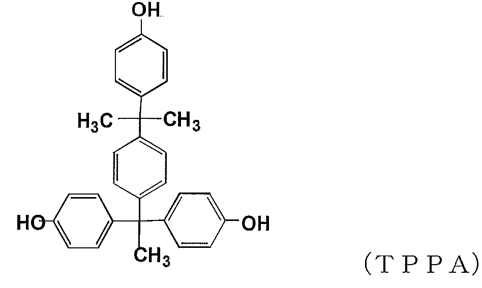
樹脂の原料および溶媒を、DSDFBP91.5g(0.228mol)、DFBP33.2g(0.152mol)、TMBPF94.5g(0.369mol)、下式で表されるTPPA4.8g(0.011mol)および炭酸カリウム65.7g(0.475mol)、ならびにDMSO895.9gおよびトルエン298.6gとした他は樹脂合成例1と同様にしてポリマー粉181.7g(収率87%)(樹脂7)を得た。諸物性評価結果を表1に示す。
樹脂の原料および溶媒を、DSDFBP91.5g(0.228mol)、DFBP33.2g(0.152mol)、TMBPF94.5g(0.369mol)、下式で表されるTPPA4.8g(0.011mol)および炭酸カリウム65.7g(0.475mol)、ならびにDMSO895.9gおよびトルエン298.6gとした他は樹脂合成例1と同様にしてポリマー粉181.7g(収率87%)(樹脂7)を得た。諸物性評価結果を表1に示す。
樹脂の原料および溶媒を、DSDFBPの代わりにDSDCDPS63.1g(0.152mol)、DFBPの代わりにDCDPS65.5g(0.228mol)、TMBPF97.4g(0.380mol)および炭酸カリウム65.7g(0.475mol)、ならびにDMSO903.9gおよびトルエン301.3gとした他は実施例1と同様にしてポリマー粉160.2g(収率76%)(樹脂8)を得た。諸物性評価結果を表1に示す。
[実施例1]
樹脂合成例1で製造した樹脂1をDMFに溶解させてワニスを調製し、このワニスを離型シート上にキャストし、150℃で10分乾燥して樹脂1の膜を得た。これを離型シートから剥離して自立膜とし半透膜1を得た。
樹脂合成例1で製造した樹脂1をDMFに溶解させてワニスを調製し、このワニスを離型シート上にキャストし、150℃で10分乾燥して樹脂1の膜を得た。これを離型シートから剥離して自立膜とし半透膜1を得た。
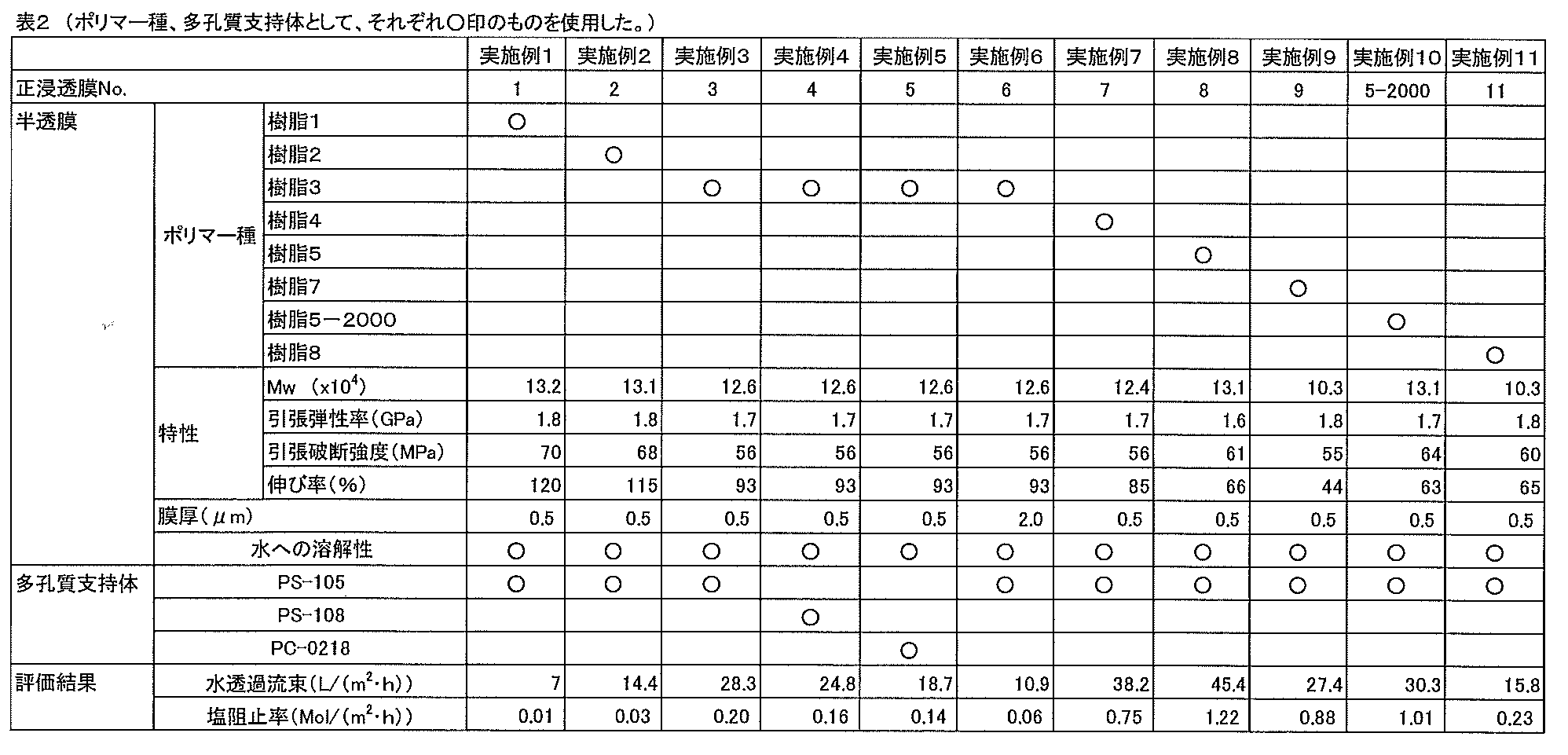
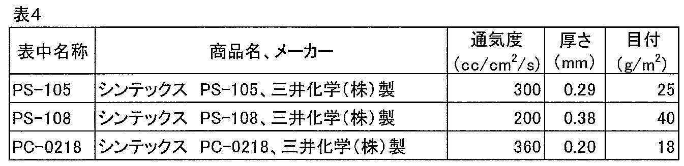
次に、JIS L 1096記載のA法(フラジール形法)で測定される通気度が300m3/cm2/s、厚さが290μm、材質がポリプロピレンである不織布(シンテックス(登録商標) PS-105 三井化学(株)製)を2枚準備し、これらの不織布で前記半透膜1を挟み、これらを一体化させて、正浸透膜1を得た。正浸透膜1の評価結果を表2に示す。
[実施例2~9、11]
半透膜の製造に使用した樹脂、半透膜の膜厚、または多孔質支持体を表2に記載のとおり変更したこと以外は実施例1と同様の方法により、正浸透膜2~9、11を得た。正浸透膜2~9、11の評価結果を表2に示す。
半透膜の製造に使用した樹脂、半透膜の膜厚、または多孔質支持体を表2に記載のとおり変更したこと以外は実施例1と同様の方法により、正浸透膜2~9、11を得た。正浸透膜2~9、11の評価結果を表2に示す。
[実施例10]
樹脂5をNMPに溶解させてワニスを調製し、このワニスをガラス基板上にキャストし、150℃で10分間乾燥して樹脂5の膜を得た。得られた膜に対して、メタルハライドランプを用いて2000mJ/cm2の光照射を行い、半透膜5を得た。半透膜5をガラス基板から剥離して自立膜とした後、不織布で挟み、これらを一体化させて、正浸透膜5-2000を得た。正浸透膜5-2000の評価結果を表2に示す。
樹脂5をNMPに溶解させてワニスを調製し、このワニスをガラス基板上にキャストし、150℃で10分間乾燥して樹脂5の膜を得た。得られた膜に対して、メタルハライドランプを用いて2000mJ/cm2の光照射を行い、半透膜5を得た。半透膜5をガラス基板から剥離して自立膜とした後、不織布で挟み、これらを一体化させて、正浸透膜5-2000を得た。正浸透膜5-2000の評価結果を表2に示す。


樹脂合成例3で製造した樹脂3をDMFに溶解させてワニスを調製し、このワニスを多孔質支持体層および多孔質ポリマー層からなる日東電工(株)製NF膜(商品名:NTR7450)の多孔質ポリマー層上にキャストし、150℃で10分乾燥して樹脂3の膜を得た。これをそのまま正浸透膜として評価に供した。評価結果を表6に示す。なお、このNF膜の、JIS L 1096記載のA法(フラジール形法)で測定される通気度、厚さ、水透過流束および塩阻止率は、それぞれ2cm3/cm2/s、145μm、25.6L/(m2・h)、3.2mol/(m2・h)であった。
[比較例2、3]
多孔質支持体層、多孔質ポリマー層および三酢酸セルロースの半透膜層からなるHTI社製正浸透膜CTA-ESおよびCTA-NWを比較として評価に供した。これらの層構成および評価結果を表5、6に示す。
多孔質支持体層、多孔質ポリマー層および三酢酸セルロースの半透膜層からなるHTI社製正浸透膜CTA-ESおよびCTA-NWを比較として評価に供した。これらの層構成および評価結果を表5、6に示す。


1 フィード溶液タンク
2、12 流路
3、13 ポンプ
4、14 天秤
10 評価装置
11 ドロー溶液タンク
15 電気伝導度計
21 評価用セル
22 正浸透膜
DS ドロー溶液
FS フィード溶液
2、12 流路
3、13 ポンプ
4、14 天秤
10 評価装置
11 ドロー溶液タンク
15 電気伝導度計
21 評価用セル
22 正浸透膜
DS ドロー溶液
FS フィード溶液
Claims (9)
- 半透膜と、その少なくとも一方の面に配置された多孔質基材とを備える正浸透膜であって、
前記半透膜は、下記式(1)で表される構造単位(1)および下記式(2)で表される構造単位(2)を含むプロトン酸基含有芳香族ポリエーテル樹脂を含んでなり、
前記多孔質基材は、JIS L 1096記載のA法(フラジール形法)で測定される100~400cm3/cm2/sの通気度、および50~700μmの厚さを有する
正浸透膜。

R1~R10は、それぞれ独立して、H、Cl、F、CF3またはCmH2m+1(mは1~10の整数を示す。)であり、
R1~R10の少なくとも1つはCmH2m+1(mは1~10の整数を示す。)であり、
R1~R10は、それぞれ芳香環に2つ以上存在してもよく、1つの芳香環にCmH2m+1が2つ以上存在する場合には、各CmH2m+1は互いに同一であっても異なっていてもよい。
X1~X5は、それぞれ独立して、H、Cl、F、CF3またはプロトン酸基であり、
X1~X5の少なくとも1つはプロトン酸基であり、
X1~X5は、それぞれ芳香環に2つ以上存在してもよく、1つの芳香環にプロトン酸基が2つ以上存在する場合には、各プロトン酸基は互いに同一であっても異なっていてもよい。
A1~A6は、それぞれ独立して、直接結合、-CH2-、-C(CH3)2-、-C(CF3)2-、-O-または-CO-である。
i,j,kおよびlは、それぞれ独立して、0または1を示す。] - 前記構造単位(1)および前記構造単位(2)の合計量に対する前記構造単位(1)および前記構造単位(2)のモル分率をそれぞれpおよびqとすると、p/q=10/90~70/30である請求項1に記載の正浸透膜。
- 前記プロトン酸基含有芳香族ポリエーテル樹脂の重量平均分子量が70,000以上である請求項1または2に記載の正浸透膜。
- 前記半透膜の厚さが3μm以下である請求項1~3のいずれか一項に記載の正浸透膜。
- 引張破断強度および伸び率が、それぞれ40MPa以上および40%以上である、請求項1~4のいずれか一項に記載の正浸透膜。
- 前記半透膜と、その両面に配置された前記多孔質基材とを有する請求項1~5のいずれか一項に記載の正浸透膜。
- 請求項1~6のいずれか一項に記載の正浸透膜およびスペーサーを備える正浸透膜エレメント。
- 請求項7に記載の正浸透膜エレメントを容器に収容してなる正浸透膜モジュール。
- 請求項8に記載の正浸透膜モジュール、および前記正浸透膜モジュールが備える前記正浸透膜の一方の面にフィード溶液を、もう一方の面に前記フィード溶液よりも高濃度のドロー溶液を流すための駆動ポンプを有し、前記フィード溶液に含まれる水を、前記正浸透膜を通して前記ドロー溶液へ移動させることのできるように構成されたシステム。
Priority Applications (1)
| Application Number | Priority Date | Filing Date | Title |
|---|---|---|---|
| JP2018547797A JP6722296B2 (ja) | 2016-10-27 | 2017-10-27 | 正浸透膜およびその用途 |
Applications Claiming Priority (2)
| Application Number | Priority Date | Filing Date | Title |
|---|---|---|---|
| JP2016210926 | 2016-10-27 | ||
| JP2016-210926 | 2016-10-27 |
Publications (1)
| Publication Number | Publication Date |
|---|---|
| WO2018079733A1 true WO2018079733A1 (ja) | 2018-05-03 |
Family
ID=62023605
Family Applications (1)
| Application Number | Title | Priority Date | Filing Date |
|---|---|---|---|
| PCT/JP2017/038973 Ceased WO2018079733A1 (ja) | 2016-10-27 | 2017-10-27 | 正浸透膜およびその用途 |
Country Status (2)
| Country | Link |
|---|---|
| JP (1) | JP6722296B2 (ja) |
| WO (1) | WO2018079733A1 (ja) |
Cited By (9)
| Publication number | Priority date | Publication date | Assignee | Title |
|---|---|---|---|---|
| WO2019189548A1 (ja) * | 2018-03-29 | 2019-10-03 | 三井化学株式会社 | 溶質濃度が低下した溶液の製造方法 |
| WO2019189547A1 (ja) * | 2018-03-29 | 2019-10-03 | 三井化学株式会社 | 正浸透膜およびその用途 |
| WO2020032019A1 (ja) * | 2018-08-06 | 2020-02-13 | 三井化学株式会社 | 正浸透膜およびその用途 |
| WO2021110954A1 (en) | 2019-12-05 | 2021-06-10 | Solvay Specialty Polymers Usa, Llc | Process for preparing a poly(aryl ether sulfone) (paes) polymer |
| JP2021123648A (ja) * | 2020-02-05 | 2021-08-30 | 三井化学株式会社 | イオン交換膜 |
| JP2021159850A (ja) * | 2020-03-31 | 2021-10-11 | 三井化学株式会社 | 正浸透膜の製造方法 |
| JP2021159851A (ja) * | 2020-03-31 | 2021-10-11 | 三井化学株式会社 | 正浸透膜の製造方法 |
| WO2021246517A1 (ja) * | 2020-06-05 | 2021-12-09 | 日本ゼオン株式会社 | ロール加工性、バンバリー加工性、耐水性、強度特性及び耐圧縮永久歪み特性に優れるアクリルゴムベール |
| CN117491245A (zh) * | 2023-11-06 | 2024-02-02 | 广州美域医学检验有限公司 | 一种评价树脂材料盐渗透性的方法 |
Families Citing this family (2)
| Publication number | Priority date | Publication date | Assignee | Title |
|---|---|---|---|---|
| JP7684824B2 (ja) * | 2021-03-25 | 2025-05-28 | 三井化学株式会社 | 正浸透膜 |
| JP7716206B2 (ja) * | 2021-03-25 | 2025-07-31 | 三井化学株式会社 | 正浸透膜の製造方法 |
Citations (4)
| Publication number | Priority date | Publication date | Assignee | Title |
|---|---|---|---|---|
| JP2014000533A (ja) * | 2012-06-19 | 2014-01-09 | Mitsui Chemicals Inc | 微多孔性支持膜用樹脂組成物およびそれを用いた微多孔性支持膜、並びに複合半透膜 |
| JP2015147153A (ja) * | 2012-12-14 | 2015-08-20 | 東レ株式会社 | 半透膜の製造方法 |
| WO2016056547A1 (ja) * | 2014-10-07 | 2016-04-14 | 東洋紡株式会社 | 分離膜および分離膜エレメントおよび分離膜モジュール |
| JP2016147260A (ja) * | 2009-08-24 | 2016-08-18 | オアシス ウォーター,インコーポレーテッド | 正浸透膜 |
-
2017
- 2017-10-27 WO PCT/JP2017/038973 patent/WO2018079733A1/ja not_active Ceased
- 2017-10-27 JP JP2018547797A patent/JP6722296B2/ja active Active
Patent Citations (4)
| Publication number | Priority date | Publication date | Assignee | Title |
|---|---|---|---|---|
| JP2016147260A (ja) * | 2009-08-24 | 2016-08-18 | オアシス ウォーター,インコーポレーテッド | 正浸透膜 |
| JP2014000533A (ja) * | 2012-06-19 | 2014-01-09 | Mitsui Chemicals Inc | 微多孔性支持膜用樹脂組成物およびそれを用いた微多孔性支持膜、並びに複合半透膜 |
| JP2015147153A (ja) * | 2012-12-14 | 2015-08-20 | 東レ株式会社 | 半透膜の製造方法 |
| WO2016056547A1 (ja) * | 2014-10-07 | 2016-04-14 | 東洋紡株式会社 | 分離膜および分離膜エレメントおよび分離膜モジュール |
Cited By (20)
| Publication number | Priority date | Publication date | Assignee | Title |
|---|---|---|---|---|
| JPWO2019189547A1 (ja) * | 2018-03-29 | 2021-03-25 | 三井化学株式会社 | 正浸透膜およびその用途 |
| WO2019189547A1 (ja) * | 2018-03-29 | 2019-10-03 | 三井化学株式会社 | 正浸透膜およびその用途 |
| WO2019189548A1 (ja) * | 2018-03-29 | 2019-10-03 | 三井化学株式会社 | 溶質濃度が低下した溶液の製造方法 |
| JPWO2019189548A1 (ja) * | 2018-03-29 | 2021-03-25 | 三井化学株式会社 | 溶質濃度が低下した溶液の製造方法 |
| JPWO2020032019A1 (ja) * | 2018-08-06 | 2021-08-26 | 三井化学株式会社 | 正浸透膜およびその用途 |
| WO2020032019A1 (ja) * | 2018-08-06 | 2020-02-13 | 三井化学株式会社 | 正浸透膜およびその用途 |
| JP7208999B2 (ja) | 2018-08-06 | 2023-01-19 | 三井化学株式会社 | 正浸透膜およびその用途 |
| WO2021110954A1 (en) | 2019-12-05 | 2021-06-10 | Solvay Specialty Polymers Usa, Llc | Process for preparing a poly(aryl ether sulfone) (paes) polymer |
| CN114786795A (zh) * | 2019-12-05 | 2022-07-22 | 索尔维特殊聚合物美国有限责任公司 | 用于制备聚(芳基醚砜)(paes)聚合物的方法 |
| JP2023504822A (ja) * | 2019-12-05 | 2023-02-07 | ソルベイ スペシャルティ ポリマーズ ユーエスエー, エルエルシー | ポリ(アリールエーテルスルホン)(paes)ポリマーを調製するプロセス |
| JP2021123648A (ja) * | 2020-02-05 | 2021-08-30 | 三井化学株式会社 | イオン交換膜 |
| JP7576399B2 (ja) | 2020-02-05 | 2024-10-31 | 三井化学株式会社 | イオン交換膜 |
| JP7508253B2 (ja) | 2020-03-31 | 2024-07-01 | 三井化学株式会社 | 正浸透膜の製造方法 |
| JP2021159850A (ja) * | 2020-03-31 | 2021-10-11 | 三井化学株式会社 | 正浸透膜の製造方法 |
| JP2021159851A (ja) * | 2020-03-31 | 2021-10-11 | 三井化学株式会社 | 正浸透膜の製造方法 |
| WO2021246517A1 (ja) * | 2020-06-05 | 2021-12-09 | 日本ゼオン株式会社 | ロール加工性、バンバリー加工性、耐水性、強度特性及び耐圧縮永久歪み特性に優れるアクリルゴムベール |
| JPWO2021246517A1 (ja) * | 2020-06-05 | 2021-12-09 | ||
| JP7806691B2 (ja) | 2020-06-05 | 2026-01-27 | 日本ゼオン株式会社 | ロール加工性、バンバリー加工性、耐水性、強度特性及び耐圧縮永久歪み特性に優れるアクリルゴムベール |
| CN117491245A (zh) * | 2023-11-06 | 2024-02-02 | 广州美域医学检验有限公司 | 一种评价树脂材料盐渗透性的方法 |
| CN117491245B (zh) * | 2023-11-06 | 2024-12-17 | 广州美域医学检验有限公司 | 一种评价树脂材料盐渗透性的方法 |
Also Published As
| Publication number | Publication date |
|---|---|
| JP6722296B2 (ja) | 2020-07-15 |
| JPWO2018079733A1 (ja) | 2019-10-03 |
Similar Documents
| Publication | Publication Date | Title |
|---|---|---|
| JP6722296B2 (ja) | 正浸透膜およびその用途 | |
| WO2019189548A1 (ja) | 溶質濃度が低下した溶液の製造方法 | |
| JP6944044B2 (ja) | 正浸透膜およびその用途 | |
| JP6018790B2 (ja) | 分離膜、この製造方法および分離膜を含む水処理装置 | |
| EP3603776B1 (en) | Spiral-wound type gas separation membrane element, gas separation membrane module, and gas separation device | |
| US20120190764A1 (en) | Aromatic polysulfone resin and membranes thereof | |
| JP6743962B2 (ja) | ガス分離膜、ガス分離膜エレメント及びガス分離方法 | |
| US20220251300A1 (en) | Bio-based polysulfones and uses thereof | |
| Li et al. | Synthesis and characterization of novel sulfonated polyimides from 1, 4-bis (4-aminophenoxy)-naphthyl-2, 7-disulfonic acid | |
| JP7716206B2 (ja) | 正浸透膜の製造方法 | |
| KR102150149B1 (ko) | 폴리아미드 계면중합용 조성물, 이를 이용한 수처리 분리막의 제조 방법 및 수처리 분리막 | |
| JP7684824B2 (ja) | 正浸透膜 | |
| JP7508254B2 (ja) | 正浸透膜の製造方法 | |
| JP7208999B2 (ja) | 正浸透膜およびその用途 | |
| JP7576399B2 (ja) | イオン交換膜 | |
| US20130327701A1 (en) | Separation membrane and water treatment device including a separation membrane | |
| JP7508253B2 (ja) | 正浸透膜の製造方法 | |
| EP3053641B1 (en) | Water-treatment separation membrane comprising ionic exchange polymer layer and method for forming same | |
| JP2021159850A (ja) | 正浸透膜の製造方法 | |
| Aiba et al. | Effect of primary structure on permselectivity of ultrathin semipermeable polybenzimidazole membrane | |
| KR102182178B1 (ko) | 수처리 분리막의 제조 방법 및 이에 의하여 제조된 수처리 분리막 | |
| KR20130011987A (ko) | 분리막, 이의 제조 방법 및 분리막을 포함하는 수처리 장치 | |
| CN104248917B (zh) | 一种反渗透膜及其制备方法 | |
| KR20220081283A (ko) | 가교구조의 폴리이미드계 유기용매 나노여과막 및 그 제조방법 | |
| KR102786115B1 (ko) | 폴리아미드 계면중합용 조성물 및 이를 이용한 수처리 분리막의 제조 방법 |
Legal Events
| Date | Code | Title | Description |
|---|---|---|---|
| 121 | Ep: the epo has been informed by wipo that ep was designated in this application |
Ref document number: 17863949 Country of ref document: EP Kind code of ref document: A1 |
|
| ENP | Entry into the national phase |
Ref document number: 2018547797 Country of ref document: JP Kind code of ref document: A |
|
| NENP | Non-entry into the national phase |
Ref country code: DE |
|
| 122 | Ep: pct application non-entry in european phase |
Ref document number: 17863949 Country of ref document: EP Kind code of ref document: A1 |