WO2018078995A1 - ボート - Google Patents
ボート Download PDFInfo
- Publication number
- WO2018078995A1 WO2018078995A1 PCT/JP2017/027880 JP2017027880W WO2018078995A1 WO 2018078995 A1 WO2018078995 A1 WO 2018078995A1 JP 2017027880 W JP2017027880 W JP 2017027880W WO 2018078995 A1 WO2018078995 A1 WO 2018078995A1
- Authority
- WO
- WIPO (PCT)
- Prior art keywords
- flange portion
- fender
- flange
- boat
- locking
- Prior art date
- Legal status (The legal status is an assumption and is not a legal conclusion. Google has not performed a legal analysis and makes no representation as to the accuracy of the status listed.)
- Ceased
Links
Images


Classifications
-
- B—PERFORMING OPERATIONS; TRANSPORTING
- B63—SHIPS OR OTHER WATERBORNE VESSELS; RELATED EQUIPMENT
- B63B—SHIPS OR OTHER WATERBORNE VESSELS; EQUIPMENT FOR SHIPPING
- B63B59/00—Hull protection specially adapted for vessels; Cleaning devices specially adapted for vessels
- B63B59/02—Fenders integral with waterborne vessels or specially adapted therefor, e.g. fenders forming part of the hull or incorporated in the hull; Rubbing-strakes
-
- B—PERFORMING OPERATIONS; TRANSPORTING
- B63—SHIPS OR OTHER WATERBORNE VESSELS; RELATED EQUIPMENT
- B63H—MARINE PROPULSION OR STEERING
- B63H7/00—Propulsion directly actuated on air
- B63H7/02—Propulsion directly actuated on air using propellers
Definitions
- This invention relates to a boat, and more particularly to a boat having a fender.
- Patent Document 1 discloses a lifeboat equipped with a shock absorber.
- the lifeboat has an upper structure and a lower structure, and the shock absorber is provided by a locking member disposed on each of the upper structure and the lower structure, and a belt member spanned over the locking member. Fastened and fixed to the upper structure and the lower structure.
- the main object of the present invention is to provide a boat that can reduce the number of parts by not requiring parts for attaching fenders.
- a lower structure including a lower body having a first edge, and a first flange portion protruding downward from the first edge and outside the lower body;
- An upper structure including an upper body having a second edge joined to one edge, and a second flange protruding from the second edge so as to be located above and outside the upper body, and the first flange And a fender that is attached to the lower structure and the upper structure so as to cover the second flange portion, and the fender is located upward between the lower body and the first flange portion.
- a first locking portion protruding toward the bottom, a second locking portion protruding downward to be positioned between the upper body and the second flange portion, and a first locking portion and a second locking portion
- a boat is provided having an intermediate section connecting the two.
- the fender covers the first flange portion and the second flange portion, the first locking portion is located between the lower body and the first flange portion, and the second locking portion is the upper body. It attaches to a lower structure and an upper structure so that it may be located between 2nd flange parts. Therefore, when the fender is subjected to a force from below, the first locking portion is locked by the lower structure, and when the fender is subjected to a force from above, the second locking portion is Locked by the superstructure.
- the first locking portion is locked by the first flange portion
- the second locking portion is Locked by the second flange portion.
- the first flange portion, the second flange portion, and the fender are provided at least in front of the boat. In this case, even if the boat moves forward, even if it comes into contact with an obstacle in front, the impact can be suppressed by the fender.
- the first flange portion, the second flange portion, and the fender are also provided on both left and right side portions of the boat. In this case, even if the boat comes into contact with an obstacle on both the left and right sides, the impact can be suppressed by the fender.
- a hollow portion is provided between the intermediate portion and the first flange portion and the second flange portion.
- the impact can be further suppressed by the air in the hollow portion.
- buoyancy can be obtained by the air in the hollow portion. This makes it easier for the boat to float.
- the specific gravity of the fender is less than 1. In this case, when the fender is immersed in water, buoyancy can be obtained by the fender. This makes it easier for the boat to float.
- the fender is flexible. In this case, since the fender can be deformed and attached to the lower structure and the upper structure, the fender can be easily attached.
- the first locking portion is formed so as to be in close contact with the first flange portion and the lower main body facing the first flange portion
- the second locking portion is formed on the second flange portion and the second flange portion. It forms so that it may closely_contact
- the fender is firmly fixed to the lower structure and the upper structure without rattling. This makes it possible to stably suppress the impact received by the boat when an obstacle comes into contact with the fender.
- the present invention further includes a driving source and a propeller that rotates based on the rotation of the driving source, and the driving source and the propeller are a pesticide spraying boat provided above the lower end of the upper structure.
- a boat for spraying agricultural chemicals is suitably used for spraying agricultural chemicals on paddy fields or the like filled with water. In this case, even if the boat for spraying agricultural chemicals comes into contact with an obstacle such as a basket, the impact can be suppressed by the fender, so that the agricultural chemical can be easily sprayed to every corner of the paddy field.
- a boat can be obtained in which the number of parts can be reduced by not requiring parts for attaching a fender.
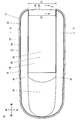
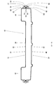
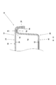
- FIG. 3 is an AA end view of FIG. 2. It is an enlarged view which shows the fender of FIG. 3, and its vicinity.
- FIG. 3 is a BB end view of FIG. 2.
- front and rear, left and right, and top and bottom mean front and rear, left and right, and top and bottom with reference to the agricultural chemical spray boat 10.
- a pesticide spraying boat 10 includes a hull 12, a propulsion device 14, and a spraying device 16.
- the hull 12 extends in the front-rear direction and curves so that the front end portion is located slightly above.
- a propulsion device 14 is provided at the upper rear portion of the hull 12.
- a spraying device 16 is provided at the center of the upper surface of the hull 12.
- the hull 12 includes an upper structure 18, a lower structure 20 and a fender 22.
- illustration of the propulsion device 14 and the spraying device 16 is omitted in order to prevent the drawing from becoming complicated.
- the upper structure 18 includes an upper body 24, a second flange portion 26, and a fourth flange portion 28.
- the upper body 24 includes a top plate part 30, a side wall part 32, a second edge part 34, and a fourth edge part 36.
- the top plate portion 30 extends in the front-rear direction, and the front portion and the left and right rear portions are formed in a substantially arc shape. Further, the top plate portion 30 includes a deck portion 38 extending in the front-rear direction, a bow portion 40 extending forward and obliquely upward from the front end portion of the deck portion 38, and both left and right sides of the deck portion 38 and the bow portion 40.
- the side wall portion 32 is formed so as to protrude downward along a portion of the outer peripheral portion of the top plate portion 30 excluding the rear range C1.
- the second edge portion 34 is formed so as to protrude substantially horizontally along the lower end portion of the side wall portion 32.
- the fourth edge portion 36 is formed so as to extend in the left-right direction along the rear end portion of the deck portion 38 and project substantially horizontally.
- the second flange portion 26 is formed so as to protrude upward along the distal end portion of the second edge portion 34.
- the fourth flange portion 28 is formed so as to extend in the left-right direction along the distal end portion of the fourth edge 36 and protrude downward.
- the lower structure 20 includes a lower main body 46, a first flange portion 48, and a third flange portion 50.
- the lower body 46 includes a bottom part 52, a side wall part 54, a first edge part 56 and a third edge part 58.
- the bottom portion 52 is formed in a thin plate shape extending in the front-rear direction, and is curved so that the front end portion is located slightly above.
- the front portion and the left and right rear portions of the bottom portion 52 are formed in a substantially arc shape like the front portion and the left and right rear portions of the top plate portion 30.
- the side wall portion 54 is formed so as to protrude upward over the entire circumference of the outer peripheral portion of the bottom portion 52.
- the first edge portion 56 protrudes substantially horizontally along a portion of the upper end portion of the side wall portion 54 excluding the range C1 so as to overlap the second edge portion 34 in plan view (see FIG. 2). It is formed.
- the third edge portion 58 extends in the left-right direction along the portion formed in the range C1 in the upper end portion of the side wall portion 54 so as to overlap the fourth edge portion 36 in plan view (see FIG. 2) and is substantially horizontal. It is formed to protrude.
- the first flange portion 48 is formed so as to protrude downward along the distal end portion of the first edge portion 56 so as to overlap the second flange portion 26 in a plan view (see FIG. 2).
- the third flange portion 50 is formed so as to extend in the left-right direction along the distal end portion of the third edge portion 58 and to protrude downward so as to overlap the fourth flange portion 28.
- the lower structure 20 and the upper structure 18 are provided so as to face each other.
- the second edge 34 of the upper structure 18 is bonded to the first edge 56 of the lower structure 20 by the adhesive member 59
- the fourth edge 36 of the upper structure 18 is bonded to the lower structure by the adhesive member 59. Bonded to the third edge 58 of the body 20.
- the first flange portion 48 is located outside the lower body 46
- the second flange portion 26 is located outside the upper body 24. Further, by providing the first flange portion 48 and the second flange portion 26 in the vicinity of the bonding portion between the lower structure 20 and the upper structure 18, the strength of the hull 12 can be increased.
- the fender 22 is formed in a substantially C-shaped cross section, covers the first flange portion 48 and the second flange portion 26, and the first flange portion 48 and the second flange portion. 26 is attached to the lower structure 20 and the upper structure 18.
- the fender 22 includes a first locking part 60, a second locking part 62, and an intermediate part 64.
- the first locking portion 60 protrudes upward so as to be positioned between the side wall portion 54 and the first flange portion 48. Further, the upper portion of the first locking portion 60 is in close contact with the side wall portion 54 and the first flange portion 48.
- the second locking portion 62 protrudes downward so as to be positioned between the side wall portion 32 and the second flange portion 26.
- the lower portion of the second locking portion 62 is in close contact with the side wall portion 32 and the second flange portion 26.
- the first locking portion 60 protrudes upward so as to be positioned between the lower main body 46 and the first flange portion 48.
- the first locking portion 60 is formed so as to be in close contact with the first flange portion 48 and the lower main body 46 facing the first flange portion 48.
- the second locking portion 62 protrudes downward so as to be positioned between the upper main body 24 and the second flange portion 26.
- the second locking portion 62 is formed so as to be in close contact with the second flange portion 26 and the upper main body 24 facing the second flange portion 26.
- the intermediate portion 64 connects the lower end portion of the first locking portion 60 and the upper end portion of the second locking portion 62, and is formed to swell slightly outward. Further, the first locking portion 60, the second locking portion 62, and the intermediate portion 64 are the first flange portion 48 in the portion of the outer peripheral portion of the lower structure 20 and the upper structure 18 excluding the rear range C ⁇ b> 1. And the second flange portion 26.
- the fender 22 for example, a flexible material such as rubber or plastic can be used.
- the specific gravity of the fender 22 is preferably set to less than 1.
- first flange portion 48, the second flange portion 26, and the fender 22 are provided at the front portion and the left and right side portions of the agricultural chemical spraying boat 10. Further, the first flange portion 48, the second flange portion 26, and the fender 22 are provided in the same range in the outer peripheral portion of the agricultural chemical spraying boat 10.
- first locking portion 60 is first pulled downward, and first locking portion 60 is moved from the lower end portion of first flange portion 48 to first flange portion 48. And the side wall portion 54.
- second locking portion 62 is pulled upward, and the second locking portion 62 is fitted between the second flange portion 26 and the side wall portion 32 from above the upper end portion of the second flange portion 26.
- the fender 22 is slid along the outer peripheral portions (the first flange portion 48 and the second flange portion 26) of the lower structure 20 and the upper structure 18, thereby preventing fenders.
- the material 22 can also be attached to the lower structure 20 and the upper structure 18.
- the first locking portion 60 is interposed between the first flange portion 48 and the side wall portion 54 from the end D of the first flange portion 48 and the second flange portion 26.
- the second locking portion 62 is inserted between the second flange portion 26 and the side wall portion 32.
- the fender 22 should just be slid along the outer peripheral part (the 1st flange part 48 and the 2nd flange part 26) of the lower structure 20 and the upper structure 18 from the state.
- the agricultural chemical spraying boat 10 has the hollow portion 66 between the intermediate portion 64 and the first flange portion 48 and the second flange portion 26.
- the propulsion device 14 includes an engine 68, a propeller 70, a rudder 72, and an electrical component 74.
- the engine 68 is mounted on the upper structure 18 via the engine mount 76.
- the propeller 70 is attached to the rear portion of the engine 68 and rotates based on the rotation of the engine 68.
- the rudder 72 is mounted on the upper structure 18 so as to be rotatable in the left-right direction behind the propeller 70.
- the electrical component 74 has a radio control receiver and the like, and is attached above the engine 68 by a support member (not shown).
- the engine 68, the propeller 70, the rudder 72, and the electrical component 74 are provided above the lower end portion of the upper structure 18.
- the propulsion apparatus used for the well-known various agrochemical spray boat can be utilized as the propulsion apparatus 14, detailed description is abbreviate
- the spraying device 16 includes a tank 78 filled with agricultural chemicals.
- the tank 78 is mounted on the upper structure 18.
- a pipe (not shown) is connected to the tank 78, and the agricultural chemical is discharged from the bottom of the hull 12 through this pipe.
- the spraying apparatus used for the well-known various agricultural chemical spraying boat can be utilized as the spraying apparatus 16, detailed description is abbreviate
- the agricultural chemical spraying boat 10 When spraying agricultural chemicals using the agricultural chemical spraying boat 10, for example, the agricultural chemical spraying boat 10 is floated on a paddy field, and the agricultural chemical spraying boat 10 is operated by a remote controller (not shown). If the agricultural chemical is sprayed into the water from the bottom of the agricultural chemical spraying boat 10 while the agricultural chemical spraying boat 10 is running, the agricultural chemical can be sprayed where the agricultural chemical spraying boat 10 has passed.
- the fender 22 covers the first flange portion 48 and the second flange portion 26, and the first locking portion 60 has the lower main body 46 and the first flange portion 48.
- the second locking portion 62 is attached to the lower structure 20 and the upper structure 18 so as to be positioned between the upper main body 24 and the second flange portion 26. Therefore, when the fender 22 receives a force from below, the first locking portion 60 is locked by the lower structure 20, and when the fender 22 receives a force from above, the second The locking part 62 is locked by the upper structure 18.
- the first locking portion 60 is locked by the first flange portion 48.
- the second locking part 62 is locked by the second flange part 26.
- the 1st flange part 48, the 2nd flange part 26, and the fender 22 are provided in the front part of the agrochemical spraying boat 10, when the agrochemical spraying boat 10 advances, it will contact with the obstacle ahead. However, the impact can be suppressed by the fenders 22.
- the first flange portion 48, the second flange portion 26, and the fender 22 are also provided on the left and right side portions of the pesticide spraying boat 10, so that the pesticide spray boat 10 comes into contact with obstacles on both the left and right sides. However, the impact can be suppressed by the fenders 22.
- the hollow portion 66 is provided between the intermediate portion 64 and the first flange portion 48 and the second flange portion 26, the air in the hollow portion 66 when an obstacle comes into contact with the intermediate portion 64 of the fender 22. Can further suppress the impact. Further, when the fender 22 is immersed in water, buoyancy can be obtained by the air in the hollow portion 66. This makes it easier for the agricultural chemical spraying boat 10 to float.
- the specific gravity of the fender 22 is set to less than 1, buoyancy can be obtained by the fender 22 when the fender 22 is immersed in water. This makes it easier for the agricultural chemical spraying boat 10 to float.
- the fender 22 Since the fender 22 has flexibility, the fender 22 can be deformed and attached to the lower structure 20 and the upper structure 18. This facilitates attachment of the fender 22.
- the first locking portion 60 is formed so as to be in close contact with the first flange portion 48 and the lower main body 46 facing the first flange portion 48
- the second locking portion 62 is formed with the second flange portion 26 and the second flange 46. Since the fender 22 is formed in close contact with the upper body 24 facing the portion 26, the fender 22 is firmly fixed to the lower structure 20 and the upper structure 18 without rattling. Thereby, the impact received by the agricultural chemical spraying boat 10 when an obstacle comes into contact with the fender 22 can be stably suppressed.
- the agrochemical spray boat 10 includes an engine 68 and a propeller 70 that rotates based on the rotation of the engine 68, and the engine 68 and the propeller 70 are provided above the lower end portion of the upper structure 18. It is preferably used for spraying agricultural chemicals on the paddy field. In this case, even if the agricultural chemical spraying boat 10 comes into contact with an obstacle such as a paddle, the impact prevention material 22 can suppress the impact, so that the agricultural chemical can be easily sprayed to every corner of the paddy field.
- first flange portion, the second flange portion, and the fender may be provided only at the front portion of the agricultural chemical spraying boat, or may be provided at the rear portion of the agricultural chemical spraying boat.
- the first flange portion, the second flange portion, and the fender can be provided at positions suitable for the type and application of the boat.
- the 1st flange part 48, the 2nd flange part 26, and the fender 22 were demonstrated in the outer peripheral part of the agricultural chemical spraying boat 10, the case where it was provided in the same range, it was limited to this.
- the first flange portion, the second flange portion, and the fender may not be provided in the same range in the outer peripheral portion of the agricultural chemical spray boat.
- the specific gravity of the fender 22 may not be less than 1, and the fender 22 may not have flexibility.
- the first locking portion 60 is formed so as to be in close contact with the first flange portion 48 and the lower main body 46 facing the first flange portion 48
- the second locking portion 62 is formed with the second flange.
- locking part is the 1st flange part 48 and the 1st flange.
- the second locking portion may not be formed so as to be in close contact with the lower main body 46 facing the portion 48, and the second locking portion may be in close contact with the upper main body 24 facing the second flange portion 26 and the second flange portion 26. It may not be formed.
- the present invention is not limited to this, and the engine 68 and the propeller 70 may be the lower structure. 20 may be provided above the lower end of 20.
Landscapes
- Chemical & Material Sciences (AREA)
- Engineering & Computer Science (AREA)
- Combustion & Propulsion (AREA)
- Mechanical Engineering (AREA)
- Ocean & Marine Engineering (AREA)
- Catching Or Destruction (AREA)
Abstract
農薬散布用ボート10は、下部本体46および第1フランジ部48を含む下部構造体20と、上部本体24および第2フランジ部26を含む上部構造体18と、第1フランジ部48と第2フランジ部26とを覆うように下部構造体20と上部構造体18とに取り付けられる防舷材22とを備える。防舷材22は、上方に向かって突出する第1係止部60と、下方に向かって突出する第2係止部62と、第1係止部60と第2係止部62とをつなぐ中間部64とを有する。防舷材22は、第1フランジ部48と第2フランジ部26とを覆い、第1係止部60が下部本体46と第1フランジ部48との間に位置しかつ第2係止部62が上部本体24と第2フランジ部26との間に位置するように、下部構造体20と上部構造体18とに取り付けられる。
Description
この発明はボートに関し、より特定的には、防舷材を有するボートに関する。
この種の従来技術の一例として、特許文献1には、緩衝体が取り付けられた救命艇が開示されている。この救命艇は、上部構造体および下部構造体を有し、緩衝体は、上部構造体および下部構造体のそれぞれに配置された係止部材と、係止部材に掛け渡されるベルト部材とによって、上部構造体および下部構造体に締め付け固定される。
このように、特許文献1の救命艇では、緩衝体を上部構造体および下部構造体に固定するために別途ベルト部材や係止部材が必要であり、部品数が多くなる。
それゆえにこの発明の主たる目的は、防舷材を取り付けるための部品を必要としないことによって部品数を減らすことができる、ボートを提供することである。
この発明の或る見地によれば、第1縁部を有する下部本体、および第1縁部から下方かつ下部本体の外部に位置するように突出する第1フランジ部を含む下部構造体と、第1縁部に接合される第2縁部を有する上部本体、および第2縁部から上方かつ上部本体の外部に位置するように突出する第2フランジ部を含む上部構造体と、第1フランジ部と第2フランジ部とを覆うように下部構造体と上部構造体とに取り付けられる防舷材とを備え、防舷材は、下部本体と第1フランジ部との間に位置するように上方に向かって突出する第1係止部、上部本体と第2フランジ部との間に位置するように下方に向かって突出する第2係止部、および第1係止部と第2係止部とをつなぐ中間部を有する、ボートが提供される。
この発明では、防舷材は、第1フランジ部と第2フランジ部とを覆い、第1係止部が下部本体と第1フランジ部との間に位置しかつ第2係止部が上部本体と第2フランジ部との間に位置するように、下部構造体と上部構造体とに取り付けられる。したがって、防舷材が下方から力を受けた場合には、第1係止部が下部構造体によって係止され、防舷材が上方から力を受けた場合には、第2係止部が上部構造体によって係止される。また、防舷材がボートとは反対側に(外方に)引っ張られるように力を受けた場合には、第1係止部が第1フランジ部によって係止され、第2係止部が第2フランジ部によって係止される。このように、防舷材を取り付けるための部品がなくても、防舷材を下部構造体および上部構造体から外れないように取り付けることができ、部品数を減らすことができる。
好ましくは、第1フランジ部と第2フランジ部と防舷材とは、当該ボートの少なくとも前部に設けられる。この場合、ボートが前進したときに前方にある障害物と接触しても、防舷材によって衝撃を抑制することができる。
また好ましくは、第1フランジ部と第2フランジ部と防舷材とは、当該ボートの左右両側部にも設けられる。この場合、ボートが左右両側方にある障害物と接触しても、防舷材によって衝撃を抑制することができる。
さらに好ましくは、中間部と、第1フランジ部および第2フランジ部との間に中空部を有する。この場合、防舷材の中間部に障害物が接触したときに、中空部にある空気によって、さらに衝撃を抑制することができる。また、防舷材が水に浸かったときに、中空部にある空気によって浮力を得ることができる。これによって、ボートが浮きやすくなる。
好ましくは、防舷材の比重は1未満である。この場合、防舷材が水に浸かったときに、防舷材によって浮力を得ることができる。これによって、ボートが浮きやすくなる。
また好ましくは、防舷材は可撓性を有する。この場合、防舷材を変形させて下部構造体と上部構造体とに取り付けることができるので、防舷材の取り付けが容易になる。
さらに好ましくは、第1係止部は、第1フランジ部および第1フランジ部に対向する下部本体に密着するように形成され、第2係止部は、第2フランジ部および第2フランジ部に対向する上部本体に密着するように形成される。この場合、防舷材は、がたつくことなく下部構造体と上部構造体とに強く固定される。これによって、防舷材に障害物が接触したときにボートが受ける衝撃を安定して抑制することができる。
好ましくは、この発明は、駆動源と駆動源の回転に基づいて回転するプロペラとをさらに備え、駆動源とプロペラとは上部構造体の下端部よりも上方に設けられる農薬散布用ボートである。このような、農薬散布用ボートは、水が張られた水田等に農薬を散布するために好適に用いられる。この場合、農薬散布用ボートが畦などの障害物と接触しても防舷材によって衝撃を抑制することができるため、水田の隅々まで容易に農薬を散布することができる。
この発明によれば、防舷材を取り付けるための部品を必要としないことによって部品数を減らすことができる、ボートが得られる。
以下、図面を参照してこの発明の好ましい実施形態について説明する。ここでは、この発明を、ボートの一例である農薬散布用ボート10に適用した場合について説明する。なお、この発明の実施形態における、前後、左右、上下とは、農薬散布用ボート10を基準とした前後、左右、上下を意味する。
図1を参照して、この発明の一実施形態に係る農薬散布用ボート10は、艇体12、推進装置14および散布装置16を含む。艇体12は、前後方向に延び、前端部がやや上方に位置するように湾曲する。艇体12の上面後部には、推進装置14が設けられる。艇体12の上面中央部には、散布装置16が設けられる。
図1~図4を参照して、艇体12は、上部構造体18、下部構造体20および防舷材22を含む。なお、図2では、図面が煩雑になることを避けるために、推進装置14および散布装置16の図示を省略する。
図5をも参照して、上部構造体18は、上部本体24、第2フランジ部26および第4フランジ部28を含む。上部本体24は、天板部30、側壁部32、第2縁部34および第4縁部36を含む。天板部30は、前後方向に延び、前部および左右後部は、略円弧状に形成される。また、天板部30は、前後方向に延びる甲板部38、甲板部38の前端部から前方斜め上方に延びた後にさらに前方に延びる船首部40、ならびに甲板部38および船首部40の左右両側方において前後方向に延びる左舷部42,右舷部44を有する。側壁部32は、天板部30の外周部のうち後部の範囲C1を除いた部分に沿ってかつ下方に突出するように形成される。第2縁部34は、側壁部32の下端部に沿ってかつ略水平に突出するように形成される。第4縁部36は、甲板部38の後端部に沿って範囲C1を左右方向に延びかつ略水平に突出するように形成される。第2フランジ部26は、第2縁部34の先端部に沿ってかつ上方に突出するように形成される。第4フランジ部28は、第4縁部36の先端部に沿って範囲C2を左右方向に延びかつ下方に突出するように形成される。
下部構造体20は、下部本体46、第1フランジ部48および第3フランジ部50を含む。下部本体46は、底部52、側壁部54、第1縁部56および第3縁部58を含む。底部52は、前後方向に延びる薄板状に形成され、前端部がやや上方に位置するように湾曲する。底部52の前部および左右後部は、天板部30の前部および左右後部のように、略円弧状に形成される。側壁部54は、底部52の外周部の全周に亘ってかつ上方に突出するように形成される。第1縁部56は、平面視(図2参照)において第2縁部34と重なるように、側壁部54の上端部のうち範囲C1を除いた部分に沿ってかつ略水平に突出するように形成される。第3縁部58は、平面視(図2参照)において第4縁部36と重なるように、側壁部54の上端部のうち範囲C1に形成される部分に沿って左右方向に延びかつ略水平に突出するように形成される。第1フランジ部48は、平面視(図2参照)において第2フランジ部26と重なるように、第1縁部56の先端部に沿ってかつ下方に突出するように形成される。第3フランジ部50は、第4フランジ部28と重なるように、第3縁部58の先端部に沿って範囲C2を左右方向に延びかつ下方に突出するように形成される。
下部構造体20と上部構造体18とは、相互に対向するように設けられる。上部構造体18の第2縁部34は、接着部材59によって、下部構造体20の第1縁部56に接着され、上部構造体18の第4縁部36は、接着部材59によって、下部構造体20の第3縁部58に接着される。下部構造体20と上部構造体18とが接着された状態では、第1フランジ部48は下部本体46の外部に位置し、第2フランジ部26は上部本体24の外部に位置する。また、下部構造体20と上部構造体18との接着部分の近傍に第1フランジ部48および第2フランジ部26を設けることによって、艇体12の強度を高めることができる。
図1~図4を参照して、防舷材22は、断面略C字状に形成され、第1フランジ部48と第2フランジ部26とを覆いかつ第1フランジ部48と第2フランジ部26とに沿うようにして、下部構造体20と上部構造体18とに取り付けられる。防舷材22は、第1係止部60、第2係止部62および中間部64を含む。第1係止部60は、側壁部54と第1フランジ部48との間に位置するように上方に向かって突出する。また、第1係止部60の上部は、側壁部54と第1フランジ部48とに密着する。第2係止部62は、側壁部32と第2フランジ部26との間に位置するように下方に向かって突出する。また、第2係止部62の下部は、側壁部32と第2フランジ部26とに密着する。言い換えれば、第1係止部60は、下部本体46と第1フランジ部48との間に位置するように上方に向かって突出する。また、第1係止部60は、第1フランジ部48と第1フランジ部48に対向する下部本体46とに密着するように形成される。第2係止部62は、上部本体24と第2フランジ部26との間に位置するように下方に向かって突出する。また、第2係止部62は、第2フランジ部26と第2フランジ部26に対向する上部本体24とに密着するように形成される。中間部64は、第1係止部60の下端部と第2係止部62の上端部とを繋ぎ、やや外方に膨らむように形成される。また、第1係止部60と第2係止部62と中間部64とは、下部構造体20および上部構造体18の外周部のうち後部の範囲C1を除く部分において、第1フランジ部48と第2フランジ部26とに沿って延びる。防舷材22としては、たとえば、ゴムやプラスチック等の可撓性を有する材料を用いることができる。防舷材22の比重は、1未満に設定されることが好ましい。
このように、第1フランジ部48と第2フランジ部26と防舷材22とは、農薬散布用ボート10の前部と左右両側部とに設けられる。また、第1フランジ部48と第2フランジ部26と防舷材22とは、農薬散布用ボート10の外周部において、同一範囲に設けられる。
防舷材22を下部構造体20と上部構造体18とに取り付けるときは、たとえば、第1フランジ部48と第2フランジ部26とを上下から挟むように取り付けることができる。図4を参照して、この場合には、まず、第1係止部60を下方に引っ張り、第1フランジ部48の下端部よりも下方から、第1係止部60を第1フランジ部48と側壁部54との間に嵌め込む。次に、第2係止部62を上方に引っ張り、第2フランジ部26の上端部よりも上方から、第2係止部62を第2フランジ部26と側壁部32との間に嵌め込む。
また、他の方法として、たとえば、防舷材22を下部構造体20および上部構造体18の外周部(第1フランジ部48および第2フランジ部26)に沿って摺動させることで、防舷材22を下部構造体20と上部構造体18とに取り付けることもできる。図2をも参照して、この場合には、第1フランジ部48および第2フランジ部26の端部Dから、第1係止部60を第1フランジ部48と側壁部54との間に挿入し、かつ第2係止部62を第2フランジ部26と側壁部32との間に挿入する。そして、その状態から、防舷材22を下部構造体20および上部構造体18の外周部(第1フランジ部48および第2フランジ部26)に沿って摺動させればよい。
図2~図4を参照して、防舷材22を下部構造体20と上部構造体18とに取り付けた状態では、中間部64と、第1フランジ部48および第2フランジ部26との間に、中空部66が形成される。中空部66は、下部構造体20および上部構造体18の外周部のうち後部の範囲C1を除く部分において、第1フランジ部48と第2フランジ部26と中間部64とに沿って延びる。このように、農薬散布用ボート10は、中間部64と、第1フランジ部48および第2フランジ部26との間に中空部66を有する。
図1を参照して、推進装置14は、エンジン68、プロペラ70、舵72および電装品74を含む。
エンジン68は、エンジンマウント76を介して、上部構造体18上に取り付けられる。プロペラ70は、エンジン68の後部に取り付けられ、エンジン68の回転に基づいて回転する。舵72は、プロペラ70の後方において、左右方向に回動自在となるように、上部構造体18上に取り付けられる。電装品74は、ラジコン受信機等を有し、図示しない支持部材によって、エンジン68の上方に取り付けられる。
上述したことから明らかなように、エンジン68とプロペラ70と舵72と電装品74とは、上部構造体18の下端部よりも上方に設けられる。なお、推進装置14としては、公知の種々の農薬散布用ボートに用いられる推進装置を利用できるので、詳細な説明は省略する。
散布装置16は、農薬が充填されるタンク78を含む。タンク78は、上部構造体18上に取り付けられる。タンク78には、図示しないパイプが接続され、このパイプを介して、艇体12の底から農薬が吐出される。なお、散布装置16としては、公知の種々の農薬散布用ボートに用いられる散布装置を利用できるので、詳細な説明は省略する。
農薬散布用ボート10を用いて農薬を散布する場合には、たとえば、農薬散布用ボート10を水田に浮かべて、図示しないリモコンによって、農薬散布用ボート10を操作する。農薬散布用ボート10を走行させながら、農薬散布用ボート10の底から農薬を水中に散布すれば、農薬散布用ボート10が通過したところに農薬を散布することができる。
このような農薬散布用ボート10によれば、防舷材22は、第1フランジ部48と第2フランジ部26とを覆い、第1係止部60が下部本体46と第1フランジ部48との間に位置しかつ第2係止部62が上部本体24と第2フランジ部26との間に位置するように、下部構造体20と上部構造体18とに取り付けられる。したがって、防舷材22が下方から力を受けた場合には、第1係止部60が下部構造体20によって係止され、防舷材22が上方から力を受けた場合には、第2係止部62が上部構造体18によって係止される。また、防舷材22が農薬散布用ボート10とは反対側に(外方に)引っ張られるように力を受けた場合には、第1係止部60が第1フランジ部48によって係止され、第2係止部62が第2フランジ部26によって係止される。このように、防舷材22を取り付けるための部品がなくても、防舷材22を下部構造体20および上部構造体18から外れないように取り付けることができ、部品数を減らすことができる。
第1フランジ部48と第2フランジ部26と防舷材22とは、農薬散布用ボート10の前部に設けられるので、農薬散布用ボート10が前進したときに前方にある障害物と接触しても、防舷材22によって衝撃を抑制することができる。
第1フランジ部48と第2フランジ部26と防舷材22とは、農薬散布用ボート10の左右両側部にも設けられるので、農薬散布用ボート10が左右両側方にある障害物と接触しても、防舷材22によって衝撃を抑制することができる。
中間部64と、第1フランジ部48および第2フランジ部26との間に中空部66を有するので、防舷材22の中間部64に障害物が接触したときに、中空部66にある空気によって、さらに衝撃を抑制することができる。また、防舷材22が水に浸かったときに、中空部66にある空気によって浮力を得ることができる。これによって、農薬散布用ボート10が浮きやすくなる。
防舷材22の比重を1未満に設定すれば、防舷材22が水に浸かったときに、防舷材22によって浮力を得ることができる。これによって、農薬散布用ボート10が浮きやすくなる。
防舷材22は可撓性を有するので、防舷材22を変形させて下部構造体20と上部構造体18とに取り付けることができる。これによって、防舷材22の取り付けが容易になる。
第1係止部60は、第1フランジ部48および第1フランジ部48に対向する下部本体46に密着するように形成され、第2係止部62は、第2フランジ部26および第2フランジ部26に対向する上部本体24に密着するように形成されるので、防舷材22は、がたつくことなく下部構造体20と上部構造体18とに強く固定される。これによって、防舷材22に障害物が接触したときに農薬散布用ボート10が受ける衝撃を安定して抑制することができる。
農薬散布用ボート10は、エンジン68とエンジン68の回転に基づいて回転するプロペラ70とを備え、エンジン68とプロペラ70とは上部構造体18の下端部よりも上方に設けられるので、水が張られた水田等に農薬を散布するために、好適に用いられる。この場合、農薬散布用ボート10が畦などの障害物と接触しても防舷材22によって衝撃を抑制することができるため、水田の隅々まで容易に農薬を散布することができる。
上述した実施形態では、第1フランジ部48と第2フランジ部26と防舷材22とが、農薬散布用ボート10の前部と左右両側部とに設けられる場合について説明したが、これに限定されず、第1フランジ部と第2フランジ部と防舷材とは、農薬散布用ボートの前部にのみ設けられてもよく、農薬散布用ボートの後部にも設けられてもよい。第1フランジ部と第2フランジ部と防舷材とは、ボートの種類や用途に応じて適した位置に設けることができる。
上述した実施形態では、第1フランジ部48と第2フランジ部26と防舷材22とが、農薬散布用ボート10の外周部において、同一範囲に設けられる場合について説明したが、これに限定されず、第1フランジ部と第2フランジ部と防舷材とは、農薬散布用ボートの外周部において、同一範囲に設けられなくてもよい。
上述した実施形態では、農薬散布用ボート10が、中空部66を有する場合について説明したが、これに限定されず、中空部66を有していなくてもよい。
防舷材22としては、ゴムやプラスチック以外の材料を用いることもできる。
防舷材22の比重は1未満でなくてもよく、防舷材22は可撓性を有していなくてもよい。
上述した実施形態では、第1係止部60が、第1フランジ部48および第1フランジ部48に対向する下部本体46に密着するように形成され、第2係止部62が、第2フランジ部26および第2フランジ部26に対向する上部本体24に密着するように形成される場合について説明したが、これに限定されず、第1係止部は、第1フランジ部48および第1フランジ部48に対向する下部本体46に密着するように形成されていなくてもよく、第2係止部は、第2フランジ部26および第2フランジ部26に対向する上部本体24に密着するように形成されていなくてもよい。
上述した実施形態では、エンジン68とプロペラ70とが、上部構造体18の下端部よりも上方に設けられる場合について説明したが、これに限定されず、エンジン68とプロペラ70とは、下部構造体20の下端部よりも上方に設けられてもよい。
上述した実施形態では、この発明を、農薬散布用ボート10に適用した場合について説明したが、これに限定されず、この発明は、公知の種々のボートに適用できる。
以上、この発明の好ましい実施形態について説明されたが、この発明の範囲および精神を逸脱しない限りにおいて種々の変更が可能であることは明らかである。この発明の範囲は、添付された請求の範囲のみによって限定される。
10 農薬散布用ボート
12 艇体
14 推進装置
16 散布装置
18 上部構造体
20 下部構造体
22 防舷材
24 上部本体
26 第2フランジ部
34 第2縁部
46 下部本体
48 第1フランジ部
56 第1縁部
60 第1係止部
62 第2係止部
64 中間部
66 中空部
68 エンジン
70 プロペラ
12 艇体
14 推進装置
16 散布装置
18 上部構造体
20 下部構造体
22 防舷材
24 上部本体
26 第2フランジ部
34 第2縁部
46 下部本体
48 第1フランジ部
56 第1縁部
60 第1係止部
62 第2係止部
64 中間部
66 中空部
68 エンジン
70 プロペラ
Claims (8)
- 第1縁部を有する下部本体、および前記第1縁部から下方かつ前記下部本体の外部に位置するように突出する第1フランジ部を含む下部構造体と、
前記第1縁部に接合される第2縁部を有する上部本体、および前記第2縁部から上方かつ前記上部本体の外部に位置するように突出する第2フランジ部を含む上部構造体と、
前記第1フランジ部と前記第2フランジ部とを覆うように前記下部構造体と前記上部構造体とに取り付けられる防舷材とを備え、
前記防舷材は、前記下部本体と前記第1フランジ部との間に位置するように上方に向かって突出する第1係止部、前記上部本体と前記第2フランジ部との間に位置するように下方に向かって突出する第2係止部、および前記第1係止部と前記第2係止部とをつなぐ中間部を有する、ボート。 - 前記第1フランジ部と前記第2フランジ部と前記防舷材とは、当該ボートの少なくとも前部に設けられる、請求項1に記載のボート。
- 前記第1フランジ部と前記第2フランジ部と前記防舷材とは、当該ボートの左右両側部にも設けられる、請求項2に記載のボート。
- 前記中間部と、前記第1フランジ部および前記第2フランジ部との間に中空部を有する、請求項1から3のいずれかに記載のボート。
- 前記防舷材の比重は1未満である、請求項1から4のいずれかに記載のボート。
- 前記防舷材は可撓性を有する、請求項1から5のいずれかに記載のボート。
- 前記第1係止部は、前記第1フランジ部および前記第1フランジ部に対向する前記下部本体に密着するように形成され、
前記第2係止部は、前記第2フランジ部および前記第2フランジ部に対向する前記上部本体に密着するように形成される、請求項1から6のいずれかに記載のボート。 - 駆動源と前記駆動源の回転に基づいて回転するプロペラとをさらに備え、前記駆動源と前記プロペラとは前記上部構造体の下端部よりも上方に設けられる農薬散布用ボートである、請求項1から7のいずれかに記載のボート。
Applications Claiming Priority (2)
| Application Number | Priority Date | Filing Date | Title |
|---|---|---|---|
| JP2016-209093 | 2016-10-25 | ||
| JP2016209093A JP6395788B2 (ja) | 2016-10-25 | 2016-10-25 | ボート |
Publications (1)
| Publication Number | Publication Date |
|---|---|
| WO2018078995A1 true WO2018078995A1 (ja) | 2018-05-03 |
Family
ID=62024710
Family Applications (1)
| Application Number | Title | Priority Date | Filing Date |
|---|---|---|---|
| PCT/JP2017/027880 Ceased WO2018078995A1 (ja) | 2016-10-25 | 2017-08-01 | ボート |
Country Status (3)
| Country | Link |
|---|---|
| JP (1) | JP6395788B2 (ja) |
| TW (1) | TW201815628A (ja) |
| WO (1) | WO2018078995A1 (ja) |
Cited By (2)
| Publication number | Priority date | Publication date | Assignee | Title |
|---|---|---|---|---|
| WO2024083702A1 (en) | 2022-10-20 | 2024-04-25 | Tessilmare S.R.L. | Fender for boats with adapter |
| WO2024194282A1 (en) | 2023-03-23 | 2024-09-26 | Tessilmare S.R.L. A Socio Unico | Dual-cavity fender for boats |
Citations (8)
| Publication number | Priority date | Publication date | Assignee | Title |
|---|---|---|---|---|
| JPS57144794U (ja) * | 1981-03-07 | 1982-09-11 | ||
| JPS57179593U (ja) * | 1981-05-11 | 1982-11-13 | ||
| JPH0516877A (ja) * | 1991-07-08 | 1993-01-26 | Yamaha Motor Co Ltd | 小型船舶の防舷材構造 |
| JPH1191685A (ja) * | 1997-09-26 | 1999-04-06 | Sekisui Plastics Co Ltd | 防舷材 |
| JP2001323438A (ja) * | 2000-05-12 | 2001-11-22 | Sumitomo Rubber Ind Ltd | 防舷材 |
| JP2011245945A (ja) * | 2010-05-25 | 2011-12-08 | Nishi-F Co Ltd | 防舷材とそれを備えた船舶 |
| JP2015000596A (ja) * | 2013-06-13 | 2015-01-05 | 株式会社タカキタ | 船首側に空中ラダーを設けた船舶 |
| JP2015083433A (ja) * | 2013-10-25 | 2015-04-30 | 株式会社エルモ | 接着式防汚防舷材 |
-
2016
- 2016-10-25 JP JP2016209093A patent/JP6395788B2/ja active Active
-
2017
- 2017-08-01 WO PCT/JP2017/027880 patent/WO2018078995A1/ja not_active Ceased
- 2017-08-14 TW TW106127426A patent/TW201815628A/zh unknown
Patent Citations (8)
| Publication number | Priority date | Publication date | Assignee | Title |
|---|---|---|---|---|
| JPS57144794U (ja) * | 1981-03-07 | 1982-09-11 | ||
| JPS57179593U (ja) * | 1981-05-11 | 1982-11-13 | ||
| JPH0516877A (ja) * | 1991-07-08 | 1993-01-26 | Yamaha Motor Co Ltd | 小型船舶の防舷材構造 |
| JPH1191685A (ja) * | 1997-09-26 | 1999-04-06 | Sekisui Plastics Co Ltd | 防舷材 |
| JP2001323438A (ja) * | 2000-05-12 | 2001-11-22 | Sumitomo Rubber Ind Ltd | 防舷材 |
| JP2011245945A (ja) * | 2010-05-25 | 2011-12-08 | Nishi-F Co Ltd | 防舷材とそれを備えた船舶 |
| JP2015000596A (ja) * | 2013-06-13 | 2015-01-05 | 株式会社タカキタ | 船首側に空中ラダーを設けた船舶 |
| JP2015083433A (ja) * | 2013-10-25 | 2015-04-30 | 株式会社エルモ | 接着式防汚防舷材 |
Cited By (2)
| Publication number | Priority date | Publication date | Assignee | Title |
|---|---|---|---|---|
| WO2024083702A1 (en) | 2022-10-20 | 2024-04-25 | Tessilmare S.R.L. | Fender for boats with adapter |
| WO2024194282A1 (en) | 2023-03-23 | 2024-09-26 | Tessilmare S.R.L. A Socio Unico | Dual-cavity fender for boats |
Also Published As
| Publication number | Publication date |
|---|---|
| JP2018069812A (ja) | 2018-05-10 |
| JP6395788B2 (ja) | 2018-09-26 |
| TW201815628A (zh) | 2018-05-01 |
Similar Documents
| Publication | Publication Date | Title |
|---|---|---|
| US10195926B2 (en) | Vehicle side door structure | |
| US6125782A (en) | Small craft with G.P.S. | |
| US6883455B2 (en) | Personal watercraft and buffer member for personal watercraft | |
| JP6395788B2 (ja) | ボート | |
| JPS62125986A (ja) | 小型ジエツト推進艇 | |
| KR101470471B1 (ko) | 공기 튜브가 선체와 분리 가능한 고속단정 | |
| US4635580A (en) | Shell of small-sized marine craft | |
| US10703455B2 (en) | Jet propelled watercraft | |
| US5517939A (en) | Thermoplastic bottom inflatable boat | |
| JP2015016835A (ja) | フロアアンダーカバー構造 | |
| US20220009601A1 (en) | Watersports System and Assembly, Method of Manufacture and Dismantling | |
| US4597348A (en) | Detachable keel for small boats | |
| US6918626B2 (en) | Cover for an object subjected to an airstream | |
| KR101556924B1 (ko) | 선박 에어스포일러 | |
| KR101523465B1 (ko) | 휴대용 접이식 보트 | |
| US7707959B2 (en) | Boat with sponson | |
| JP2007176236A (ja) | エアボート | |
| JP4811918B2 (ja) | エアボート | |
| US7594834B2 (en) | Marine propulsion apparatus | |
| DE602004020328D1 (de) | Befestigung, insbesondere zur Vertauung von Fahrzeugen an Bord von Schiffen, und Verfahren zur Anbringung einer solcher Befestigung am Deck | |
| KR20130119998A (ko) | 요트 | |
| US20200369104A1 (en) | Chassis System of Amphibious Remote Control Vehicle | |
| JP4566449B2 (ja) | 水ジェット推進艇 | |
| CN211167310U (zh) | 一种碰碰船 | |
| US20080141916A1 (en) | Small Vessel Capable Of High Tow Force |
Legal Events
| Date | Code | Title | Description |
|---|---|---|---|
| 121 | Ep: the epo has been informed by wipo that ep was designated in this application |
Ref document number: 17866011 Country of ref document: EP Kind code of ref document: A1 |
|
| NENP | Non-entry into the national phase |
Ref country code: DE |
|
| 122 | Ep: pct application non-entry in european phase |
Ref document number: 17866011 Country of ref document: EP Kind code of ref document: A1 |