WO2018074412A1 - 符号化装置及び復号化装置 - Google Patents
符号化装置及び復号化装置 Download PDFInfo
- Publication number
- WO2018074412A1 WO2018074412A1 PCT/JP2017/037353 JP2017037353W WO2018074412A1 WO 2018074412 A1 WO2018074412 A1 WO 2018074412A1 JP 2017037353 W JP2017037353 W JP 2017037353W WO 2018074412 A1 WO2018074412 A1 WO 2018074412A1
- Authority
- WO
- WIPO (PCT)
- Prior art keywords
- signal
- signals
- channels
- intensity
- channel
- Prior art date
- Legal status (The legal status is an assumption and is not a legal conclusion. Google has not performed a legal analysis and makes no representation as to the accuracy of the status listed.)
- Ceased
Links
Images



Classifications
-
- H—ELECTRICITY
- H04—ELECTRIC COMMUNICATION TECHNIQUE
- H04B—TRANSMISSION
- H04B10/00—Transmission systems employing electromagnetic waves other than radio-waves, e.g. infrared, visible or ultraviolet light, or employing corpuscular radiation, e.g. quantum communication
- H04B10/50—Transmitters
- H04B10/516—Details of coding or modulation
- H04B10/54—Intensity modulation
-
- H—ELECTRICITY
- H04—ELECTRIC COMMUNICATION TECHNIQUE
- H04J—MULTIPLEX COMMUNICATION
- H04J13/00—Code division multiplex systems
- H04J13/10—Code generation
- H04J13/12—Generation of orthogonal codes
-
- H—ELECTRICITY
- H04—ELECTRIC COMMUNICATION TECHNIQUE
- H04J—MULTIPLEX COMMUNICATION
- H04J13/00—Code division multiplex systems
- H04J13/16—Code allocation
- H04J13/18—Allocation of orthogonal codes
-
- H—ELECTRICITY
- H04—ELECTRIC COMMUNICATION TECHNIQUE
- H04J—MULTIPLEX COMMUNICATION
- H04J14/00—Optical multiplex systems
- H04J14/02—Wavelength-division multiplex systems
- H04J14/0227—Operation, administration, maintenance or provisioning [OAMP] of WDM networks, e.g. media access, routing or wavelength allocation
-
- H—ELECTRICITY
- H04—ELECTRIC COMMUNICATION TECHNIQUE
- H04J—MULTIPLEX COMMUNICATION
- H04J14/00—Optical multiplex systems
- H04J14/02—Wavelength-division multiplex systems
- H04J14/03—WDM arrangements
- H04J14/0305—WDM arrangements in end terminals
-
- H—ELECTRICITY
- H04—ELECTRIC COMMUNICATION TECHNIQUE
- H04B—TRANSMISSION
- H04B10/00—Transmission systems employing electromagnetic waves other than radio-waves, e.g. infrared, visible or ultraviolet light, or employing corpuscular radiation, e.g. quantum communication
- H04B10/25—Arrangements specific to fibre transmission
- H04B10/2507—Arrangements specific to fibre transmission for the reduction or elimination of distortion or dispersion
-
- H—ELECTRICITY
- H04—ELECTRIC COMMUNICATION TECHNIQUE
- H04B—TRANSMISSION
- H04B10/00—Transmission systems employing electromagnetic waves other than radio-waves, e.g. infrared, visible or ultraviolet light, or employing corpuscular radiation, e.g. quantum communication
- H04B10/50—Transmitters
-
- H—ELECTRICITY
- H04—ELECTRIC COMMUNICATION TECHNIQUE
- H04B—TRANSMISSION
- H04B10/00—Transmission systems employing electromagnetic waves other than radio-waves, e.g. infrared, visible or ultraviolet light, or employing corpuscular radiation, e.g. quantum communication
- H04B10/50—Transmitters
- H04B10/501—Structural aspects
- H04B10/503—Laser transmitters
- H04B10/505—Laser transmitters using external modulation
-
- H—ELECTRICITY
- H04—ELECTRIC COMMUNICATION TECHNIQUE
- H04B—TRANSMISSION
- H04B10/00—Transmission systems employing electromagnetic waves other than radio-waves, e.g. infrared, visible or ultraviolet light, or employing corpuscular radiation, e.g. quantum communication
- H04B10/50—Transmitters
- H04B10/516—Details of coding or modulation
-
- H—ELECTRICITY
- H04—ELECTRIC COMMUNICATION TECHNIQUE
- H04B—TRANSMISSION
- H04B10/00—Transmission systems employing electromagnetic waves other than radio-waves, e.g. infrared, visible or ultraviolet light, or employing corpuscular radiation, e.g. quantum communication
- H04B10/50—Transmitters
- H04B10/516—Details of coding or modulation
- H04B10/548—Phase or frequency modulation
-
- H—ELECTRICITY
- H04—ELECTRIC COMMUNICATION TECHNIQUE
- H04L—TRANSMISSION OF DIGITAL INFORMATION, e.g. TELEGRAPHIC COMMUNICATION
- H04L1/00—Arrangements for detecting or preventing errors in the information received
- H04L1/004—Arrangements for detecting or preventing errors in the information received by using forward error control
- H04L1/0041—Arrangements at the transmitter end
-
- H—ELECTRICITY
- H04—ELECTRIC COMMUNICATION TECHNIQUE
- H04L—TRANSMISSION OF DIGITAL INFORMATION, e.g. TELEGRAPHIC COMMUNICATION
- H04L1/00—Arrangements for detecting or preventing errors in the information received
- H04L1/004—Arrangements for detecting or preventing errors in the information received by using forward error control
- H04L1/0045—Arrangements at the receiver end
Definitions
- the present invention relates to an encoding device and a decoding device.
- This application claims priority based on Japanese Patent Application No. 2016-204411 filed in Japan on October 18, 2016, the contents of which are incorporated herein by reference.
- 100 GbE LR-4 which is a method of Ethernet (registered trademark)
- the transmission method used here is multi-channel optical transmission in which 100 Gbps (bps: bits per second) data transmission is performed using optical signals having a plurality of different wavelengths.
- 100 Gbps bps: bits per second
- four wavelengths each wavelength is referred to as a channel
- Ethernet registered trademark
- a method using a wavelength of 1.3 ⁇ m band occupies most, and the 1.3 ⁇ m band is also used in 100 GbE LR-4. Since the zero-dispersion wavelength of the single-mode fiber is approximately 1.3 ⁇ m, there is an advantage that it is not necessary to consider waveform degradation due to wavelength dispersion in optical transmission using the 1.3 ⁇ m band.
- Ethernet registered trademark
- the number of channels used is 10. Since Ethernet (registered trademark) generally uses 800 GHz as the frequency interval of channels, the wavelength range occupied by 10 channels is approximately 60 nm. For example, when the zero dispersion wavelength of the transmission fiber is 1310 nm and the wavelength of the longest wave channel is 1310 nm in accordance with the zero dispersion wavelength, the wavelength of the shortest wave channel is approximately 1250 nm.
- the chromatic dispersion at 1250 nm is approximately 5 ps / nm / km.
- the transmission distance is assumed to be 10 km following 100 GbE LR-4, the accumulated chromatic dispersion in the channel on the shortest wave side is about 50 ps / nm. In other words, waveform degradation occurs in the shortest wave channel due to wavelength dispersion of 50 ps / nm.
- chromatic dispersion on waveform degradation depends on the channel transmission rate, and the higher the transmission rate, the greater the waveform degradation. Assuming such a situation, even in an optical transmission system using the 1.3 ⁇ m band, the influence of chromatic dispersion cannot be ignored. In particular, since the short-distance optical transmission system is based on the premise that intensity modulation is used from the viewpoint of cost reduction, dispersion compensation cannot be performed at the receiver as in the digital coherent optical transmission scheme. Therefore, the chromatic dispersion of the transmission fiber directly affects the quality of the optical signal.
- an object of the present invention is to provide an encoding device and a decoding device that can reduce signal quality variation between channels in an optical transmission system and improve signal quality.
- the encoding apparatus inputs N (N is an integer of 2 or more) intensity signals of M + 1 values (M is an integer of 1 or more), and has an N-row N-column Hadamard matrix and N Among the encoded signals of N channels of (NM + 1) values obtained by calculating an inner product with a matrix having the intensity signals as elements, the encoded signal in which the minimum value in the range of possible values is negative
- An encoding unit that performs an encoding process of adding (NM / 2) to N, and an N that corresponds to each of the N channels and converts the encoded signal of the corresponding channel from a digital signal to an electrical analog signal.
- N digital-to-analog converters N light sources that respectively correspond to the N channels and output light having a wavelength used for the corresponding channels, N channels that correspond to the N channels, Output from the light source N light intensity modulators for modulating the intensity of light by the encoded signals converted into electrical analog signals by the N digital-analog converters, and intensity modulation by the N light intensity modulators
- a wavelength combining unit that outputs a wavelength-combined signal obtained by wavelength-multiplexing the generated light.
- the encoding apparatus inputs M + 1 value (M is an integer of 1 or more) N (N is an integer of 2 or more) intensity signals, and inputs 2 L (L is an integer of 1 or more). 2 L is less than or equal to N) For each set of intensity signals, the inner product of 2 L rows 2 L columns Hadamard matrix and a matrix of 2 L intensity signals included in the set is calculated.
- N digital-to-analog converters for conversion and the N channels N light sources that output light of wavelengths used for the corresponding channels, and N light sources that correspond to the N channels and that are output from the N light sources, N light intensity modulators each performing intensity modulation with the encoded signal converted into an electrical analog signal by a digital-analog converter, and the light intensity-modulated by the N light intensity modulators is wavelength-multiplexed A wavelength multiplexing unit that outputs a wavelength synthesis signal.
- 2 L intensity signals included in each of the intensity signal sets include 2 L included in each of the intensity signal sets.
- the variation of the average value of the signal quality of the intensity signals is selected to be the minimum.
- a decoding device corresponds to a wavelength demultiplexing unit that demultiplexes a received wavelength division multiplexed signal into optical signals of N channels based on wavelengths, and corresponds to the N channels, Among the optical signals of the N channels demultiplexed by the wavelength demultiplexing unit, the optical signal of the corresponding channel is converted into an intensity signal which is an electrical signal of (NM + 1) value (M is an integer of 1 or more).
- N light receiving units N analog-to-digital conversion units that correspond to the N channels and convert the intensity signals of the corresponding channels from analog signals to digital signals, N rows and N columns of Hadamard matrices, , Of the range of possible values of the decoded signal obtained by dividing the inner product with the matrix having the intensity signal converted into the digital signal by the N analog-digital conversion units by N Add (-M (N-1) / 2) to the decoded signal with a positive small value, and add (M / 2) to the decoded signal with the smallest possible value range. And a decoding unit that performs a decoding process to obtain N (M + 1) -value decoded signals.
- the decoding unit corresponds to each of the N channels and includes (N + 1) adaptive digital filters.
- a filter unit and N determination function units respectively corresponding to the N channels, and the intensity of the i-th channel (i is an integer of 1 to N) of the N channels.
- a signal is represented by B i , and the j-th among the (N + 1) adaptive digital filters included in the filter unit corresponding to the i-th channel among the N filter units (j is an integer between 0 and N)
- the adaptive digital filter tap coefficient is represented by h ij
- the digital data processed by the filter unit corresponding to the i-th channel is represented by C i
- the N-row N-column Hadamard matrix is represented by H
- the filter unit corresponding to the i-th channel calculates digital data C i according to Equations (27) and (28) of the embodiment, and among the N determination function units,
- the determination function unit corresponding to the i-th channel performs threshold determination on the digital data C i and decodes the signal
- the initial value of the tap coefficient h ij is the expression (33) and expression (34) of the embodiment. ).
- the decoding unit corresponds to each of the N channels, and includes N adaptive digital filters.
- the filter unit corresponding to the i-th channel calculates the digital data C i according to the equation (36) of the embodiment, and the determination function unit corresponding to the i-th channel among the N determination function units. Performs threshold determination on the digital data C i and decodes the signal, and the initial value of the tap coefficient h ij is determined by the equation (40) of the embodiment.
- the tap length of the N adaptive digital filters is the maximum of the chromatic dispersion values of the N channels. Is determined based on the chromatic dispersion value.
- a decoding apparatus corresponds to a wavelength demultiplexing unit that demultiplexes a received wavelength division multiplexed signal into optical signals of N channels based on wavelengths, and corresponds to the N channels, Among the optical signals of the N channels demultiplexed by the wavelength demultiplexing unit, the optical signal of the corresponding channel is converted into an intensity signal which is an electrical signal of (NM + 1) value (M is an integer of 1 or more).
- N light receiving units, N analog-to-digital conversion units that correspond to the N channels and convert the intensity signals of the corresponding channels from analog signals to digital signals, and the N analog-to-digital conversions 2 L (L is an integer of 1 or more, 2 L is N or less) in the intensity signal of said N channels are converted into digital signals by parts for each set of pieces of the intensity signal, 2 L rows 2 Columns and Hadamard matrix, one of the 2 L-number of intensity signal set to 2 L number of said intensity signal element to the matrix and the decoded signal inner product was obtained by dividing the 2 L of contained in, taken ( ⁇ M (2 L ⁇ 1) / 2) is added to the decoded signal having a positive minimum value range, and ( ⁇ M (2 L ⁇ 1) / 2) is added to the decoded signal having a negative minimum value range.
- signal quality variation between channels in an optical transmission system can be reduced, and signal quality can be improved.
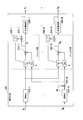
- FIG. 5 It is a figure which shows the basic composition of the optical transmission system by embodiment of this invention. It is a figure which shows the structure of the encoding apparatus of the optical transmission system by 1st Embodiment. It is a figure which shows the structure of the decoding apparatus of the optical transmission system by 1st Embodiment. It is a figure which shows the internal structure of the decoding part by 1st Embodiment. It is a figure which shows the signal quality of the optical transmission system by 1st Embodiment. It is a figure which shows the receiving power and chromatic dispersion of each channel in the simulation in which the signal quality shown in FIG. 5 was obtained. It is a figure which shows the internal structure of the decoding part by 2nd Embodiment.
- optical transmission systems so-called multi-channel optical transmission systems (hereinafter referred to as “optical transmission systems”) that perform data transmission between the same ground using a plurality of optical signals having different wavelengths. .
- a PAM4 (4-Level Pulse Amplitude Modulation) method is known. This method assigns 2 bits (bits) of data information to a four-value intensity signal that takes one of the four values ⁇ 0, 1, 2, 3 ⁇ , thereby providing 2 bits / symbol (2 per symbol). Bit) transmission.
- PAM4 4-Level Pulse Amplitude Modulation
- This method assigns 2 bits (bits) of data information to a four-value intensity signal that takes one of the four values ⁇ 0, 1, 2, 3 ⁇ , thereby providing 2 bits / symbol (2 per symbol). Bit) transmission.
- Walsh encoding to a plurality of PAM4 signals, signal quality variations between channels are leveled, and the signal quality of the entire optical transmission system is improved.
- Non-Patent Document 1 A procedure for applying conventional Walsh encoding to signals of two channels will be described below. This procedure is described in Non-Patent Document 1, for example.
- the first channel signal before encoding is A 1
- the second channel signal is A 2
- the encoded first channel signal is B 1
- the second channel signal is B 2 .
- the relationship between the signals A 1 and A 2 and the signals B 1 and B 2 is expressed by the following equation (1).
- the signals A 1 and A 2 assume a complex amplitude of a radio wave or an optical electric field. If these are binary light intensities of 0 and 1, the signals A 1 and A 2 take one of the two values ⁇ 0, 1 ⁇ , whereas the signal B 1 has ⁇ 0, 1 ⁇ . , 1, 2 ⁇ takes one of the three values, and the signal B 2 takes one of the three values ⁇ -1, 0, 1 ⁇ . In general, when the signals B 1 and B 2 are light intensities, they cannot take negative values. Therefore, the value of ⁇ 1 in the signal B 2 cannot be expressed by the light intensity. Therefore, in the present embodiment, the encoding from the signals A 1 and A 2 to the signals B 1 and B 2 is changed to the following equation (2).
- the signal B 2 also takes the three values ⁇ 0, 1, 2 ⁇ in the same manner as the signal B 1 , so that the signal B 2 can be expressed by the light intensity.
- the average light intensity of the signal A 1, A 2 is 1/2.
- the light intensity of the signal light in the optical transmission system can be adjusted by the transmission power, the following description will be made without considering the standardization of the light intensity at the time of encoding.
- the signals A 1 and A 2 are binary intensity signals that take one of the values ⁇ 0, 1 ⁇ .
- the encoding is formulated in the same procedure when assuming an intensity signal of (M + 1) value taking any one of the values of M ⁇ , that is, (M + 1) value PAM signal (M is an integer of 1 or more). Is possible. In this case, encoding is as shown in the following equation (4).
- the (NM + 1) value PAM signal is a signal indicating any one of different (NM + 1) values.
- the signal A i takes any one of the (M + 1) values of ⁇ 0, 1,..., M ⁇
- the signal B i becomes any of the (NM + 1) values of ⁇ 0, 1,. Take one.
- the optical transmission system of the present embodiment transmits the intensity signals B 1 to B N encoded in this way through each channel.
- the channel that transmits the intensity signal B i is referred to as the i-th channel.
- the matrix H N is an N ⁇ N Hadamard matrix and is represented by the following equation (6).
- N is a power of 2.
- FIG. 1 is a diagram showing a basic configuration of an optical transmission system 1 in an embodiment of the present invention.
- the optical transmission system 1 includes an encoding device 2 and a decoding device 3.
- the encoding device 2 and the decoding device 3 are connected via an optical fiber transmission line.
- the encoding device 2 includes an encoding unit 201, light sources 202-1 to 202-N, intensity modulators 203-1 to 203-N, and a wavelength multiplexer 204 (N is an integer of 2 or more). .
- the encoding unit 201 encodes the signals A 1 to A N that are (M + 1) -value PAM signals according to Expression (5), and generates signals B 1 to B N that are (NM + 1) -value PAM signals.
- the encoding unit 201 outputs the generated signals B 1 to B N.
- the intensity modulator 203-i 1, 2,..., N receives the signal B i output from the encoding unit 201 and the light output from the light source 202-i.
- Intensity modulator 203-i is the light source 202-i is output, and generates an intensity signal which has been subjected to optical amplitude modulation based on a signal B i (NM + 1) values.
- the intensity modulator 203-i outputs the generated intensity signal to the wavelength multiplexer 204.
- the wavelength combiner 204 combines a wavelength composite signal obtained by combining the intensity signals B 1 to B N of the first to N-th channels input from the intensity modulators 203-1 to 203-N with an optical fiber. Output to the transmission line.
- the decoding device 3 includes a wavelength demultiplexer 301, light receivers 302-1 to 302-N, and a decoding unit 303 (N is an integer of 2 or more).
- the signal B i is output to the light receiver 302-i.
- the light receiver 302-i outputs the signal B i converted into the electric signal to the decoding unit 303.
- Decoding section 303 receives signals B 1 to B N from light receivers 302-1 to 302-N.
- the decoding unit 303 restores the signals A 1 to A N before encoding by performing a decoding process represented by the following equation (7) on the input signals B 1 to B N.
- This equation (7) is obtained by solving equation (5) for the signal A i .
- the optical transmission system 1 encodes the intensity signals A 1 to A N and transmits them as the intensity signals B 1 to B N so that one signal A i is distributed and transmitted over a plurality of channels. To do.
- the quality degradation is dispersed to a plurality of channels by decoding. Therefore, the signal quality variation between channels is leveled, and as a result, the signal quality of the entire optical transmission system is improved.
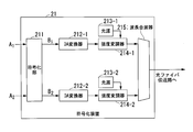
- FIG. 2 is a diagram illustrating a configuration of the encoding device 21 of the optical transmission system according to the first embodiment.
- the encoding device 21 includes an encoding unit 211, digital-analog converters (DA converters) 212-1 and 212-2, light sources 213-1 and 213-2, and intensity modulators 214-1 and 214-. 2 and a wavelength multiplexer 215.
- the signal A i before encoding is a PAM4 signal and the number of channels is two.
- the encoding unit 211 represents the signal A 1 and the signal A 2 indicating the four-value digital data taking any one of the four values ⁇ 0, 1, 2, 3 ⁇ by Expression (4).
- the signal B 1 and the signal B 2 indicating the 7-value digital data taking any one of the 7 values ⁇ 0, 1, 2, 3, 4, 5, 6 ⁇ are Generate.
- the light source 213-i (i 1, 2) outputs light having the wavelength of the i-th channel.
- the wavelength multiplexer 215 is a signal B 1 that is an optical signal of the first channel input from the intensity modulator 214-1 and a signal B that is an optical signal of the second channel input from the intensity modulator 214-2. 2 is sent to the optical fiber transmission line.
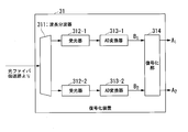
- FIG. 3 is a diagram illustrating a configuration of the decoding device 31 of the optical transmission system according to the first embodiment.
- the decoding device 31 includes a wavelength demultiplexer 311, light receivers 312-1 and 312-2, analog-digital converters (AD converters) 313-1 and 313-2, and a decoding unit 314. Is done.
- the wavelength demultiplexer 311 receives the wavelength synthesis signal output from the encoding device 21 shown in FIG. 2 and transmitted through the optical fiber transmission line.
- the decoding unit 314 inputs signals B 1 and B 2 indicating 7-value digital data of the first and second channels, respectively.
- the decoding unit 314 performs one of the four values ⁇ 0, 1, 2, 3 ⁇ by performing the decoding represented by the following equation (8) on the signal B 1 and the signal B 2 .
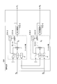
- FIG. 4 shows an internal configuration of the decoding unit 314 when the adaptive digital filter is used.
- FIG. 4 is a diagram illustrating an internal configuration of the decoding unit 314.
- Decoding section 314 includes filters h 10 , h 11 , h 12 , h 20 , h 21 , h 22 , addition sections 511-1 and 511-2, determination function sections 512-1 and 512-2, and an arithmetic operation Sections 513-1 and 513-2 and feedback sections 514-1 and 514-2.
- the filters h 10 , h 11 , h 12 , h 20 , h 21 , h 22 are adaptive digital filters.
- the following relational expressions (9) and (10) are obtained.
- the point that the adaptive filter processing is applied to the constant value in the first term on the right side in the equations (9) and (10) is a point that is greatly different from the conventional Walsh decoding, and the Walsh decoding is applied to the intensity modulation signal. This process is indispensable when applying.
- An arbitrary method can be applied as the tap coefficient updating method by the feedback units 514-1 and 514-2.
- D-LMS Decision-Directed Least-Mean-Square
- E 1 used for updating taps of filters h 10 , h 11 , h 12 and filters h 20 , h 21, respectively
- E 2 used in the tap updating h 22
- equation (12) is defined by the equation (12).
- ⁇ is a step size parameter.
- FIG. 5 is a diagram showing the signal quality of the optical transmission system according to the first embodiment.
- the figure shows the reception power of the second channel (CH2) and the bit error rate (CH1) of the first channel (CH1) when the first embodiment is applied to the PAM4 signals of two channels.
- It is a figure which shows the relationship between the average value of BER of BER: Bit (Error) Rate) and the 2nd channel (CH2).
- the figure is based on the results of numerical simulation.
- the average value of the BER of each channel is used as an index representing the signal quality of the entire system.
- FIG. 6 is a diagram showing the reception power and chromatic dispersion of each channel used in the simulation of FIG.
- each channel is a PAM4 signal realizing data transmission of 112 Gbps, and the number of channels is ten.
- the longest wavelength channel is the first channel (CH1), and the wavelength of the first channel is equal to the zero dispersion wavelength of the transmission fiber.
- the reception power of the first channel is set to -3 dBm.
- the channel with the shortest wavelength is the second channel (CH2), and the cumulative chromatic dispersion (CD) value in the second channel is 0 ps / nm or 64 ps / nm.
- the accumulated chromatic dispersion value of 64 ps / nm corresponds to the accumulated chromatic dispersion value when the single mode fiber is transmitted about 10 km.
- the encoding shown in the first embodiment is applied to the PAM4 signal of the first channel and the PAM4 signal of the second channel.
- FIG. 5 shows a case where the encoding of the first embodiment is applied to the first channel (CH1) and the second channel (CH2) shown in FIG.
- the average BER when the received power of the channel is changed is shown.
- PAM4 represents a case where Walsh encoding is not applied
- WCP represents a case where the encoding of the first embodiment is applied.
- the signal quality is equivalent regardless of whether or not encoding is applied.
- the encoding of the present embodiment when the encoding of the present embodiment is not applied, that is, when the conventional PAM4 signal is transmitted, the received power of the second channel is BER below the error correction limit (FEC limit) cannot be realized unless is -6 dBm or more.
- FEC limit error correction limit
- the encoding of the present embodiment it is possible to realize a BER equal to or lower than the FEC limit even when the reception power of the second channel is ⁇ 12 dBm. This means that by applying the encoding of the present embodiment, a characteristic improvement of 6 dB or more is obtained in terms of reception power.
- the number of taps of the adaptive digital filter is 31.
- the second embodiment is the same as the first embodiment in that Walsh encoding is performed on PAM4 signals of two channels, but the filter configuration of the decoding unit is different. That is, the second embodiment is characterized in that the number of adaptive digital filters constituting the decoding unit is reduced by improving the decoding unit of the first embodiment.
- the encoded PAM4 signal is decoded by the equation (8), but the equation (8) can be modified as the following equation (18).
- Decoding can be performed by executing the process represented by Equation (18) using an adaptive digital filter.
- FIG. 7 is a diagram illustrating an internal configuration of the decoding unit 520 according to the second embodiment.
- the decoding unit 520 is used in place of the decoding unit 314 of the first embodiment shown in FIG.
- Decoding unit 520 includes normalization units 521-1 and 521-2, addition unit 522, filters h 11 , h 12 , h 21 and h 22 , addition units 523-1 and 523-2, and a determination function.
- the filters h 11 , h 12 , h 21 , h 22 are adaptive digital filters.
- any method can be applied as the tap coefficient updating method by the feedback units 526-1 and 526-2.
- DD-LMS Decision-Directed Least-Mean-Square
- E 1 used for updating tap coefficients h 11 and h 12 and tap coefficients h 21 and h 22 are calculated.
- each error function E 2 to be used for updating is defined by the equation (22).
- ⁇ is a step size parameter.
- the number of adaptive digital filters is The feature is that h is reduced to four of h 11 , h 12 , h 21 , and h 22 .
- FIG. 8 is a diagram illustrating a configuration of the encoding device 23 of the optical transmission system according to the third embodiment.
- the encoding device 23 includes an encoding unit 231, digital-analog converters (DA converters) 232-1 to 232-N, light sources 233-1 to 233-N, and intensity modulators 234-1 to 234-. N and a wavelength multiplexer 235.
- the encoding unit 231 applies the equation (5) to the signals A 1 to A N indicating (M + 1) -value digital data that takes any one of the (M + 1) values of ⁇ 0, 1,..., M ⁇ . ),
- the signals B 1 to B N indicating the digital data of the (NM + 1) value taking any one of the (NM + 1) values of ⁇ 0, 1,..., NM ⁇ are obtained.
- the light source 233-i (i 1, 2,..., N) outputs light of the i-th channel wavelength.
- FIG. 9 is a diagram showing a configuration of the decoding device 33 of the optical transmission system according to the third embodiment.
- the decoding device 33 includes a wavelength demultiplexer 331, light receivers 332-1 to 332-N, analog-digital converters (AD converters) 333-1 to 333-N, and a decoding unit 334. Is done.
- the wavelength demultiplexer 331 receives the wavelength synthesis signal output from the encoding device 23 shown in FIG. 8 and transmitted through the optical fiber transmission line.
- the signal B i indicating the digital data of the value is converted, and the signal B i is output to the decoding unit 334.
- the decoding unit 334 receives signals B 1 to B N indicating (NM + 1) -value digital data of the first to N-th channels.
- the processing of the decoding unit 334 represented by Expression (26) is executed using, for example, an adaptive digital filter.
- FIG. 10 shows an internal configuration of the decoding unit 334 when the adaptive digital filter is used.
- FIG. 10 is a diagram illustrating an internal configuration of the decryption unit 334.
- Decoding section 334 includes filters h 10 to h 1N ,..., H N0 to h NN , addition sections 531-1 to 531-N, determination function sections 532-1 to 532-N, and calculation section 533-1. 533-N and feedback units 534-1 to 534-N.
- the filters h 10 to h 1N ,..., H N0 to h NN are adaptive digital filters.
- the point that the adaptive filter processing for the constant value is applied in the first term on the right side in the equations (27) and (28) is a point that is greatly different from the conventional Walsh decoding, and the Walsh decoding is applied to the intensity modulated signal. This process is indispensable when applying.
- any method can be applied as the tap coefficient updating method by the feedback units 534-1 to 534-N.
- DD-LMS Decision-Directed Least-Mean-Square
- the error function E i used for the tap update is defined as the following equation (29).
- ⁇ is a step size parameter.
- the fourth embodiment is the same as the third embodiment in that Walsh encoding is performed on (M + 1) -value PAM signals of N channels, but the filter configuration of the decoding unit is different. That is, the fourth embodiment is characterized in that the number of adaptive digital filters constituting the decoding unit is reduced by improving the decoding unit of the third embodiment.
- the encoded (M + 1) -value PAM signal is decoded by the equation (26), but the equation (26) can be modified as the following equation (35).
- Decoding can be performed by executing the processing represented by this equation using an adaptive digital filter.
- FIG. 11 is a diagram illustrating an internal configuration of the decoding unit 540 according to the fourth embodiment.
- the decoding unit 540 is used instead of the decoding unit 334 of the third embodiment shown in FIG.
- the decoding unit 540 includes normalization units 541-1 to 541-N, addition units 542-2 to 542-N, filters h 11 to h 1N ,..., H N1 to h NN, and an addition unit 543-1. 543-N, determination function units 544-1 to 544-N, arithmetic units 545-1 to 545-N, and feedback units 546-1 to 546-N.
- the filters h 11 to h 1N ,..., H N1 to h NN are adaptive digital filters.
- any method can be applied as the tap coefficient updating method by the feedback units 546-1 to 546-N.
- DD-LMS Decision-Directed Least-Mean-Square
- ⁇ is a step size parameter.
- the number of adaptive digital filters is reduced to N ⁇ 2.
- FIG. 12 is a diagram for explaining a case where encoding is applied to all N channels.
- encoding is applied to (M + 1) -value PAM signals of N channels.
- the signal quality can be improved without necessarily applying the encoding according to the third embodiment or the fourth embodiment to all channels. It is possible to obtain an effect.
- the first to fourth embodiments have an effect of averaging the signal quality of a plurality of channels. Therefore, the highest signal quality improvement effect is obtained when encoding is applied to all N channels.
- the number of adaptive digital filters required for decoding is N (N + 1) in the third embodiment, which is the fourth embodiment. Then N ⁇ 2. Since the number of adaptive digital filters increases in the order of the square of the number of channels, it becomes difficult from the viewpoint of circuit scale to realize a digital signal processing circuit that realizes decoding in an optical transmission system with a large number of channels N. .
- any two channels are selected from the (M + 1) -value PAM signals of N channels, and the two channels are encoded.
- FIG. 13 is a diagram for explaining selection of a channel to be encoded in the fifth embodiment.
- the number of adaptive digital filters required for decoding is reduced by applying encoding to any two channels selected from (M + 1) -value PAM signals of N channels.
- the amount of signal quality improvement effect obtained by encoding differs. Focusing on the fact that the first to fourth embodiments have the effect of averaging the signal quality of a plurality of channels, the signal quality of the entire optical transmission system can be selected by selecting two channels in the following procedure. Can be maximized.
- channel numbers are assigned to (M + 1) value PAM signals of N channels in descending order of signal quality. That is, the channel having the highest signal quality is assigned to the first channel, the channel having the next highest signal quality is assigned to the second channel, and the channel number is assigned. The channel having the lowest signal quality is assigned to the Nth channel. A channel number is assigned to each channel. For these channels assigned channel numbers in descending order of signal quality, the first channel and the Nth channel are selected as a pair, and the second channel and the (N-1) th channel are selected as a pair. Subsequently, the same i-th channel and (N ⁇ i + 1) -th channel are selected as a pair. Next, encoding is applied to each pair individually.
- the (N + 1) / 2th channel is transmitted as it is, that is, as an (M + 1) -value PAM signal.
- the reception power of each channel may be used as shown in FIG. 13, or the bit error rate or chromatic dispersion value of each channel may be used.
- FIG. 14 is a diagram illustrating a configuration of the encoding device 26 of the optical transmission system according to the fifth embodiment.
- the encoding device 26 includes encoding units 261-1 to 261-L, digital-analog converters (DA converters) 262-1 to 262-N, light sources 263-1 to 263-N, and an intensity modulator. 264-1 to 264-N and a wavelength multiplexer 265.
- N an even number
- L N / 2
- the wavelength multiplexer 265 wavelength-multiplexes the signals B 1 to B N that are optical signals of the first channel to the N-th channel inputted from the intensity modulators 264-1 to 264-N, and generates them by wavelength multiplexing.
- the wavelength-combined signal is sent to the optical fiber transmission line.
- the encoding device 26 When N is an odd number, the encoding device 26 outputs the signal A (N + 1) / 2 as it is to the DA converter 262- (N + 1) / 2 without encoding. Other operations are the same as when N is an even number.
- FIG. 15 is a diagram illustrating a configuration of the decoding device 36 of the optical transmission system according to the fifth embodiment.
- the wavelength demultiplexer 361 receives the wavelength synthesis signal output from the encoding device 26 shown in FIG. 14 and transmitted through the optical fiber transmission line.
- the same processing as that of the unit 520 is performed to restore the signals A i and A (N ⁇ i + 1) before encoding.
- the decoding unit 364-K of a decoding device 36 performs a threshold determination for the signal B K, to recover the signal A K. Threshold determination, of the Possible (M + 1) values of the signal A k, a process of obtaining the value closest to the value indicated by the signal B k. For example, the decoding unit 364-K compares each of the M threshold values determined according to the (M + 1) values that the signal A k can take with the value indicated by the signal B k, and determines the signal B based on the comparison result. A value closest to the value indicated by k may be obtained.
- the configuration of the decoding unit 364-i is the same as the configuration of the decoding unit 314 in the first embodiment shown in FIG. 4 or the configuration of the decoding unit 520 in the second embodiment shown in FIG.
- the number K of decoding units 364-1 to 364-K in the fifth embodiment is N / 2.
- the number of adaptive digital filters required in the decoding unit in the third embodiment is N (N + 1).
- the number of adaptive digital filters required in the fifth embodiment is 3N in total in the case of a decoding unit having the same configuration as in the first embodiment. Therefore, by applying the fifth embodiment, the number of adaptive digital filters can be reduced by 3 / (N + 1) times. Further, the number of adaptive digital filters required in the encoding unit in the fourth embodiment is N ⁇ 2. On the other hand, the number of adaptive digital filters required in the fifth embodiment is 2N in total in the case of a decoding unit having the same configuration as in the second embodiment. Therefore, by applying this embodiment, the number of adaptive digital filters can be reduced to 2 / N times. The larger the number N of channels constituting the optical transmission system, the greater the effect of reducing the number of adaptive digital filters.
- the configuration in which encoding and decoding are performed for each (N / 2) set including two PAM signals among the PAM signals of N channels has been described.
- Encoding and decoding may be performed for each (N / 2 L ) group including 2 L PAM signals among N channel PAM signals (L is an integer of 1 or more, 2 L is N or less) ).
- the encoding unit 261 includes a matrix having 2 L PAM signals included in each group as elements. Encoding is performed by calculating an inner product with the Hadamard matrix of L rows and 2 L columns.
- the encoding unit 261 outputs, as an encoded signal, a signal that is always a positive value among 2 L signals obtained by the inner product calculation.
- the encoding unit 261 adds (2 L M / 2) to a signal whose negative value is included in possible values among 2 L signals obtained by the inner product operation, and outputs the addition result as an encoded signal To do.
- 2 includes a L-number of PAM signal (N / 2 L) when performing coding for each number of pairs, as variations in the average value of the signal quality of 2 the L PAM signals included in each set is minimized , 2 L PAM signals included in each set are selected.
- N / 2 L L-number of PAM signal
- the PAM signal of the channel having the first highest signal quality among the N channels is selected as the PAM signal included in the first set.
- the PAM signal of the channel with the lowest signal quality is selected as the PAM signal included in the first set.
- the PAM signal of the channel with the i-th lowest signal quality is selected as the PAM signal included in the i-th set.
- the PAM signal of the channel having the highest signal quality (Q + 1) is selected as the PAM signal included in the first group.
- the PAM signal of the channel with the highest signal quality (Q + i) is selected as the PAM signal included in the i-th set.
- the (Q + 1) th channel PAM signal with the lowest signal quality is selected as the PAM signal included in the first group.
- the PAM signal of the channel with the (Q + i) th lowest signal quality is selected as the PAM signal included in the i th set.
- the PAM signal of the channel with the highest signal quality is selected as the PAM signal included in the i-th set.
- the PAM signal of the (((p-2) Q + 2)) / 2) channel having the lowest signal quality is selected as the PAM signal included in the first set.
- the (((P-2) Q + 2i)) / 2) The PAM signal of the channel with the lowest signal quality is selected as the PAM signal included in the i-th set.
- First the, second, third, fourth, procedure of the p-1 and the p (p 6,8, ..., 2 L) by performing, 2 included in each Q-number of set L PAM signals are determined.
- the procedure for selecting the 2 L PAM signals described above is an example, and another procedure for selecting to minimize the variation in the average value of the signal quality of the 2 L PAM signals may be used.
- Decoding section 364 may decode the signal for each (N / 2 L ) sets including 2 L PAM signals.
- decoding unit 364 When performing decoding for the set containing 2 L number of PAM signal, decoding unit 364, a 2 is L-number of PAM signal elements matrix, the inner product of the Hadamard matrix of 2 L rows 2 L column operation To perform decoding.
- the decoding unit 364 calculates ( ⁇ M (2L ⁇ 1)) as a signal that does not include a negative value in the range of possible values among signals obtained by dividing the signal obtained by the inner product operation by 2 L. / 2) is added, and the addition result is output as a decoding result.
- the decoding unit 364 adds (M / 2) to a signal whose negative value is included in the range of possible values among signals obtained by dividing the signal obtained by the inner product operation by 2 L. The addition result is output as a decoding result.
- the number of PAM signals included in each group may be determined in the range from 2 to N. By determining the number of PAM signals included in each group according to the calculation load, the signal quality can be improved while suppressing an increase in calculation load.
- each embodiment not only the signal quality variation due to the difference in reception power between channels but also the signal quality variation due to the difference in the degree of waveform degradation due to wavelength dispersion. , Have a signal quality leveling effect. Part of the waveform degradation due to chromatic dispersion can be compensated by an adaptive digital filter that realizes decoding. Therefore, the number of taps of the adaptive digital filter is an important parameter for compensation of waveform degradation caused by chromatic dispersion.
- the decoding in each embodiment corresponds to an operation of sharing the influence of chromatic dispersion caused by the transmission fiber among a plurality of channels
- the number of taps of the adaptive digital filter that realizes the decoding may be the same in all channels. desirable.
- attention is paid to the channel that receives the largest chromatic dispersion among the N channels.
- the channel that receives the largest chromatic dispersion among the N channels is the d-th channel, and the cumulative chromatic dispersion received by the d-th channel is D [ps / nm].
- the modulation rate of the (M + 1) -value PAM signal is F [Gbaud (gigabaud)]
- the symbol period is 1000 / F [ps].
- the bandwidth of the signal spectrum is approximately F [GHz].
- the optical waveform spread generated in the d-th channel due to the chromatic dispersion D [ps / nm] is approximately DF / 125 [ps], which corresponds to the waveform spread of DF2 / 125000 symbols.
- the waveform spread due to the chromatic dispersion is about 29 ps. This corresponds to a waveform spread of about 2 symbols. That is, there is a possibility that a synchronization shift of two symbols occurs.
- the taps of the adaptive digital filter are implemented at intervals of T / 2 with respect to the symbol period T of the signal. Accordingly, in this example, the influence of chromatic dispersion can be reduced by setting the number of taps (tap length) to 4 or more.
- the update of the vector indicating the tap coefficient h ij is performed by the equations (13) to (15), (23), (24), (30) to (32), (38), ( The signals A i , B i , and C i in 39) are performed using a time series (vector) having the same length as the number of taps.
- the encoding device includes an encoding unit, a wavelength synthesis unit, N digital-to-analog conversion units corresponding to N channels, N light sources, and N light intensities. And a modulation unit.
- the N digital-to-analog converters are, for example, DA converters 212-1, 212-2, 232-1 to 232-N.
- the N light intensity modulation units are, for example, intensity modulators 214-1, 214-2, 234-1 to 234-N.
- the wavelength multiplexers are, for example, wavelength multiplexers 215 and 235.
- the encoding unit inputs N (N is an integer of 2 or more) intensity signals of (M + 1) values (M is an integer of 1 or more).
- the encoding unit may take an encoded signal of N channels of (NM + 1) values obtained by calculating an inner product of an N-row N-column Hadamard matrix and a matrix having N intensity signals as elements.
- An encoding process is performed in which a constant (NM / 2) is added to an encoded signal having a negative minimum value range so that the minimum possible value is 0.
- the N digital-analog conversion units convert the encoded signals of the corresponding channels from digital signals to electrical analog signals.
- the N light sources output light having a wavelength used for the corresponding channel.
- the N light intensity modulation units modulate the intensity of the light output from the light source of the corresponding channel by the encoded signal converted into the electrical analog signal by the digital / analog conversion unit of the corresponding channel.
- the wavelength multiplexing unit outputs a wavelength synthesized signal obtained by wavelength-multiplexing the light intensity-modulated by each of the N light intensity modulation units.
- the decoding apparatus includes a wavelength demultiplexing unit, a decoding unit, and N light receiving units and N analog-digital conversion units provided for each of N channels.
- the wavelength demultiplexing units are, for example, wavelength demultiplexers 311 and 331.
- the N light receiving units are, for example, light receivers 312-1, 312-2, 332-1 to 332-N.
- the N analog-digital conversion units are, for example, AD converters 313-1, 313-2, 333-1 to 333-N.
- the wavelength demultiplexing unit demultiplexes the received wavelength multiplexed signal into optical signals of N channels based on the wavelength.
- the N light receiving units convert the optical signal of the channel corresponding to the own function unit among the N channels of optical signals demultiplexed by the wavelength demultiplexing unit into an intensity signal that is an electrical signal of (NM + 1) value. .
- the N analog-digital conversion units convert the intensity signals of the corresponding channels from analog signals to digital signals.
- the decoding unit performs a decoding process for obtaining a decoded signal. In the decoding process, the decoding unit divides N by the inner product of the N-row N-column Hadamard matrix and a matrix whose elements are intensity signals converted into digital signals by N analog-digital conversion units.
- the encoding unit decodes a constant ( ⁇ M (N) so that the minimum possible value is 0 for a decoded signal having a positive minimum value in the range of possible values among the decoded signals obtained as a result of division. -1) / 2) is added, and a constant (M / 2) is added to the decoded signal having a negative minimum value in the range of possible values so that the minimum possible value is zero.
- the encoding unit obtains N addition results as decoded signals of N (M + 1) values.
- the decoding unit may include N filter units each corresponding to N channels and having (N + 1) adaptive digital filters, and a determination function unit corresponding to each of the N channels.
- the intensity signal of the i-th channel (i is an integer not less than 1 and not more than N) among the N channels is represented by B i
- the filter unit corresponding to the i-th channel among the N filter units has (N + 1) pieces.
- the tap coefficient of the j-th (j is an integer from 0 to N) adaptive digital filter is h ij
- the digital data after processing by the filter unit corresponding to the i-th channel is C i
- N rows N Let H N be the Hadamard matrix of the column.
- the decoding unit may include N filter units each corresponding to N channels and having N adaptive digital filters, and determination function units respectively corresponding to the N channels.
- B i represents the intensity signal of the i-th channel (i is an integer of 1 to N) among the N channels, and N adaptive digitals included in the filter unit corresponding to the i-th channel among the N filter units.
- the tap coefficient of the j-th adaptive digital filter (j is an integer between 1 and N) is h ij
- the digital data after processing by the filter unit corresponding to the i-th channel is C i
- N rows and N columns are N rows and N columns.
- the plurality of adaptive digital filters may use the same number of taps determined based on a chromatic dispersion value of a channel having a chromatic dispersion larger than a predetermined value.
- the number of taps of all adaptive digital filters may be determined based on the chromatic dispersion value of the channel having the largest chromatic dispersion among the N channels used.
- the encoding part of an encoding apparatus produces
- the encoding unit inputs N (N is an integer of 2 or more) intensity signals of (M + 1) values (M is an integer of 1 or more), and 2 L (L is an integer of 1 or more, 2 L is equal to or less than N) For each set of intensity signals, an inner product of a Hadamard matrix of 2 L rows and 2 L columns and a matrix having 2 L intensity signals included in the set as elements is calculated.
- Encoding unit of obtained by calculating the inner product (2 L M + 1) value 2 L of pieces of channel encoded signal the encoded signal is a minimum value of the range of possible values is negative, taken A constant (2 L M / 2) is added so that the minimum value to be obtained is zero.
- the encoding unit has a positive value range of the encoded signal of the addition result and the encoded signal of 2 L channels of the (2 L M + 1) value obtained by calculating the inner product.
- the encoded signal is output as an encoded signal of N channels.
- the encoding unit is, for example, the encoding units 261-1 to 261-L, and the encoding process is expressed by, for example, Expression (4).
- Each set may be composed of an intensity signal whose signal quality is i-th (i is an integer between 1 and N / 2) and an intensity signal whose signal quality is i-th.
- the decoding unit of the encoding device performs the following decoding process.
- the decoding unit includes 2 L rows and 2 L columns of Hadamard matrices for each set of 2 L intensity signals in the N channel intensity signals converted into digital signals by each of the N analog-digital conversion units. the inner product of the matrix for the 2 L-number of intensity signals included in one set and the elements is divided by 2 L.
- the decoding unit obtains a constant ( ⁇ M (2) so that the minimum possible value is 0 for a decoded signal having a positive minimum value in the range of possible values among the decoded signals obtained by division.
- the decoding unit outputs the N addition results as a result of the decoding process.
- an appropriate channel set is extracted from a plurality of channels that transmit intensity modulated signals in a multi-channel optical transmission system, and Walsh encoding is applied to the set of channels. It is possible to level the signal quality variation between them and improve the signal quality of the entire optical transmission system.
- Some functions of the encoding devices 2, 21, 23, and 26 and the decoding devices 3, 31, 33, and 36 in the above-described embodiment may be realized by a computer.
- a program for realizing this function may be recorded on a computer-readable recording medium, and the program recorded on this recording medium may be read into a computer system and executed. It is also possible to provide a program for realizing the above-described functions through a network.
- the “computer system” here includes an OS and hardware such as peripheral devices.
- “Computer-readable recording medium” refers to a portable medium such as a flexible disk, a magneto-optical disk, a ROM, and a CD-ROM, and a storage device such as a hard disk built in a computer system.
- the “computer-readable recording medium” dynamically holds a program for a short time like a communication line when transmitting a program via a network such as the Internet or a communication line such as a telephone line.
- a volatile memory inside a computer system serving as a server or a client in that case may be included and a program held for a certain period of time.
- the above-mentioned program may be for realizing a part of the above-described functions, and may be capable of realizing the above-described functions in combination with a program already recorded in the computer system.
Landscapes
- Engineering & Computer Science (AREA)
- Computer Networks & Wireless Communication (AREA)
- Signal Processing (AREA)
- Physics & Mathematics (AREA)
- Electromagnetism (AREA)
- Optical Communication System (AREA)
Abstract
符号化装置は、符号化部とDA変換器と光源と強度変調器と波長合波器とを備える。符号化部は、N行N列のアダマール行列とN個の(M+1)値の強度信号を各要素とする行列との内積を算出して得られた(NM+1)値のN個のチャンネルの符号化信号のうち取り得る値の範囲の最小値が負の符号化信号に(NM/2)を加算する。各チャンネルのDA変換器は、符号化信号をデジタル信号から電気のアナログ信号に変換する。光源は、各チャンネルの波長の光を出力する。各チャンネルの強度変調器は、各光源から出力された光を、各DA変換器がアナログ信号に変換した符号化信号によりそれぞれ強度変調する。波長合波器は、強度変調器が強度変調した光それぞれを波長多重して出力する。
Description
本発明は、符号化装置及び復号化装置に関する。
本願は、2016年10月18日に、日本に出願された特願2016-204411号に基づき優先権を主張し、その内容をここに援用する。
本願は、2016年10月18日に、日本に出願された特願2016-204411号に基づき優先権を主張し、その内容をここに援用する。
データ通信需要の増大に伴い、大容量トラヒックの伝送を可能とする光信号変調技術や、光信号多重技術を用いた光伝送ネットワークが普及しつつある。特に、短距離向けの高速光伝送技術として、イーサネット(登録商標)の一方式である100GbE LR-4が知られている。ここで用いられる伝送方式は、100Gbps(bps:ビット毎秒)データ伝送を、複数の異なる波長を有する光信号を用いて行う、多チャンネル光伝送である。例えば、100GbE LR-4では、4つの波長(各波長をチャンネルと呼ぶ)がそれぞれ25Gbpsのデータ伝送を行うことで、全体として100Gbpsのデータ伝送を実現する。イーサネット(登録商標)では1.3μm帯の波長を用いる方式が大半を占めており、100GbE LR-4でも1.3μm帯が用いられている。シングルモードファイバのゼロ分散波長がおおよそ1.3μmであるため、1.3μm帯を用いた光伝送では、波長分散による波形劣化を考慮する必要がないという利点がある。
A. Masuda, et al., "First Experimental demonstration of signal performance improvement by the Walsh-Hadamard transform for the super-channel transmission," Proc. of Opto-Electronics and Communications Conference (OECC), 2015
将来的にイーサネット(登録商標)技術を応用して1Tbpsのデータ伝送を実現することを考えると、例えば10の波長を用いてそれぞれのチャンネルで100Gbpsのデータ伝送を行うことで、全体として1Tbpsのデータ伝送を実現する方法が考えられる。この方法を用いた場合、使用するチャンネル数は10となる。イーサネット(登録商標)ではチャンネルの周波数間隔として800GHzを用いることが一般的であるため、10個のチャンネルが占める波長範囲はおよそ60nmとなる。例えば伝送ファイバのゼロ分散波長を1310nmとし、最長波のチャンネルの波長をゼロ分散波長に合わせて1310nmとした場合、最短波のチャンネルの波長はおよそ1250nmとなる。
通常のシングルモードファイバの分散スロープはおよそ0.08ps/nm^2/kmであるため、1250nmにおける波長分散はおよそ5ps/nm/kmとなる。100GbE LR-4に倣って伝送距離を10kmと想定した場合、最短波側のチャンネルにおける累積波長分散は50ps/nm程度となる。すなわち、最短波のチャンネルは、50ps/nmの波長分散により、波形劣化が発生する。
波長分散が波形劣化に与える影響は、チャンネルの伝送速度に依存し、伝送速度が高ければ高いほど、より大きな波形劣化が発生する。このような状況を想定すると、1.3μm帯を用いた光伝送システムであっても、波長分散の影響を無視することができなくなる。特に、短距離向け光伝送システムではコスト低減の観点から、強度変調を用いることを前提としているため、デジタルコヒーレント光伝送方式のような受信器での分散補償を実施することができない。したがって、伝送ファイバの波長分散は、光信号の品質に直接影響を及ぼすものとなる。
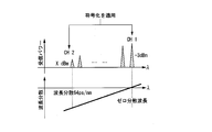
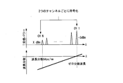
100GbE LR-4のチャンネル数が4であったのに対し、1TbEを実現するためには10個のチャンネルが必要になると考えると、100GbE LR-4の場合に比べてより短い波長の光を発生させなければならない。したがって、これまでに実績のない、技術的に未成熟な発光デバイスを使用しなければならないことが想定される。このときに考えられる懸念点として、短波側では長波側と比べて十分な送信パワーが得られないことが挙げられる。また、システムの中で使用される波長合分波器などの光デバイスにおいても同様に技術的に未成熟であることが想定されるため、短波側では損失が大きくなってしまう等の事象が発生しうる。これは、短波側の受信パワーが長波側の受信パワーに比べて小さくなってしまうことを意味し、短波側のチャンネルの信号品質が長波側のチャンネルと比べて低い信号品質になってしまうことに相当する。上記の状況を、図16に模式的に示す。
このような状況を鑑みると、1Tbpsデータ伝送などの将来の短距離光伝送技術を実現する上で、チャンネル間の信号品質のばらつきが光伝送システム全体の信号品質を劣化させる主要因となることが考えられる。
上記事情に鑑み、本発明は、光伝送システムにおけるチャンネル間の信号品質ばらつきを軽減し、信号品質を改善することができる符号化装置及び復号化装置を提供することを目的としている。
本発明の第1の態様における符号化装置は、M+1値(Mは1以上の整数)のN個(Nは2以上の整数)の強度信号を入力し、N行N列のアダマール行列とN個の前記強度信号を要素とする行列との内積を算出して得られた(NM+1)値のN個のチャンネルの符号化信号のうち取り得る値の範囲の最小値が負の前記符号化信号に(NM/2)を加算する符号化処理を行う符号化部と、前記N個のチャンネルにそれぞれ対応し、対応するチャンネルの前記符号化信号を、デジタル信号から電気のアナログ信号に変換するN個のデジタルアナログ変換部と、前記N個のチャンネルにそれぞれ対応し、対応するチャンネルに用いられる波長の光を出力するN個の光源と、前記N個のチャンネルにそれぞれ対応し、前記N個の光源から出力された前記光を、前記N個のデジタルアナログ変換部により電気のアナログ信号に変換された前記符号化信号によりそれぞれ強度変調するN個の光強度変調部と、前記N個の光強度変調部により強度変調された前記光を波長多重した波長合成信号を出力する波長合波部と、を備える。
本発明の第2の態様における符号化装置は、M+1値(Mは1以上の整数)のN個(Nは2以上の整数)の強度信号を入力し、2L(Lは1以上の整数、2LはN以下)個の前記強度信号の組ごとに、2L行2L列のアダマール行列と前記組に含まれる2L個の前記強度信号を要素とする行列との内積を算出して得られた(2LM+1)値の2L個のチャンネルの符号化信号のうち取り得る値の範囲の最小値が負である前記符号化信号に(2LM/2)を加算する符号化処理を行い、N個のチャンネルの前記符号化信号を生成する符号化部と、前記N個のチャンネルにそれぞれ対応し、対応するチャンネルの前記符号化信号を、デジタル信号から電気のアナログ信号に変換するN個のデジタルアナログ変換部と、前記N個のチャンネルにそれぞれ対応し、対応するチャンネルに用いられる波長の光を出力するN個の光源と、前記N個のチャンネルにそれぞれ対応し、前記N個の光源から出力された前記光を、前記N個のデジタルアナログ変換部により電気のアナログ信号に変換された前記符号化信号によりそれぞれ強度変調するN個の光強度変調部と、前記N個の光強度変調部により強度変調された前記光を波長多重した波長合成信号を出力する波長合波部と、を備える。
本発明の第3の態様によれば、第2の態様の符号化装置において、前記強度信号の組それぞれに含まれる2L個の前記強度信号は、前記強度信号の組それぞれに含まれる2L個の前記強度信号の信号品質の平均値のばらつきが最小となるように選択される。
本発明の第4の態様によれば、第2の態様の符号化装置において、L=1の場合、前記強度信号の組のうちi(iは1以上N/2以下の整数)番目の組は、前記N個の強度信号のうち、信号品質がi番目に高い前記強度信号と、信号品質がi番目に低い前記強度信号とにより構成される。
本発明の第5の態様の復号化装置は、受信した波長多重信号を波長に基づきN個のチャンネルの光信号に分波する波長分波部と、前記N個のチャンネルにそれぞれ対応し、前記波長分波部により分波された前記N個のチャンネルの前記光信号のうち対応するチャンネルの前記光信号を(NM+1)値(Mは1以上の整数)の電気信号である強度信号に変換するN個の受光部と、前記N個のチャンネルにそれぞれ対応し、対応するチャンネルの前記強度信号をアナログ信号からデジタル信号に変換するN個のアナログデジタル変換部と、N行N列のアダマール行列と、前記N個のアナログデジタル変換部によりデジタル信号に変換された前記強度信号を要素とする行列との内積をNで除算して得られた復号化信号のうち、取り得る値の範囲の最小値が正の前記復号化信号には(-M(N-1)/2)を加算し、取り得る値の範囲の最小値が負の前記復号化信号には(M/2)を加算してN個の(M+1)値の復号化信号を得る復号化処理を行う復号化部と、を備える。
本発明の第6の態様によれば、上述の第5の態様の復号化装置において、前記復号化部は、前記N個のチャンネルにそれぞれ対応し、(N+1)個の適応デジタルフィルタを有するN個のフィルタ部と、前記N個のチャンネルにそれぞれ対応するN個の判定機能部と、を備え、前記N個のチャンネルのうちi番目(iは1以上N以下の整数)のチャンネルの前記強度信号をBiで表し、前記N個のフィルタ部のうち前記i番目のチャンネルに対応するフィルタ部が有する前記(N+1)個の適応デジタルフィルタのうちj番目(jは0以上N以下の整数)の適応デジタルフィルタのタップ係数をhijで表し、前記i番目のチャンネルに対応した前記フィルタ部による処理後のデジタルデータをCiで表し、N行N列のアダマール行列をHNで表したときに、前記i番目のチャンネルに対応した前記フィルタ部は、実施形態の式(27)及び式(28)によりデジタルデータCiを算出し、前記N個の判定機能部のうち前記i番目のチャンネルに対応した判定機能部は、前記デジタルデータCiに閾値判定を行って信号を復号し、前記タップ係数hijの初期値は、実施形態の式(33)及び式(34)で定められる。
本発明の第7の態様によれば、上述の第5の態様の復号化装置において、前記復号化部は、前記N個のチャンネルにそれぞれ対応し、N個の適応デジタルフィルタを有するN個のフィルタ部と、前記N個のチャンネルにそれぞれ対応するN個の判定機能部と、を備え、前記N個のチャンネルのうちi番目(iは1以上N以下の整数)のチャンネルの前記強度信号をBiで表し、前記N個のフィルタ部のうち前記i番目のチャンネルに対応するフィルタ部が有する前記N個の適応デジタルフィルタのうちj番目(jは1以上N以下の整数)の適応デジタルフィルタのタップ係数をhijで表し、前記i番目のチャンネルに対応した前記フィルタ部による処理後のデジタルデータをCiで表し、N行N列のアダマール行列をHNで表したときに、前記i番目のチャンネルに対応した前記フィルタ部は、実施形態の式(36)によりデジタルデータCiを算出し、前記N個の判定機能部のうち前記i番目のチャンネルに対応した判定機能部は、前記デジタルデータCiに閾値判定を行って信号を復号し、前記タップ係数hijの初期値は、実施形態の式(40)で定められる。
本発明の第8の態様によれば、上述の第6又は第7の態様の復号化装置において、前記N個の適応デジタルフィルタのタップ長は、前記N個のチャンネルの波長分散値のうち最大の波長分散値に基づいて決定される。
本発明の第9の態様の復号化装置は、受信した波長多重信号を波長に基づきN個のチャンネルの光信号に分波する波長分波部と、前記N個のチャンネルにそれぞれ対応し、前記波長分波部により分波された前記N個のチャンネルの前記光信号のうち対応するチャンネルの前記光信号を(NM+1)値(Mは1以上の整数)の電気信号である強度信号に変換するN個の受光部と、前記N個のチャンネルにそれぞれ対応し、対応するチャンネルの前記強度信号をアナログ信号からデジタル信号に変換するN個のアナログデジタル変換部と、前記N個の前記アナログデジタル変換部によりデジタル信号に変換された前記N個のチャンネルの前記強度信号における2L(Lは1以上の整数、2LはN以下)個の前記強度信号の組ごとに、2L行2L列のアダマール行列と、前記2L個の強度信号の組に含まれる2L個の前記強度信号を要素とする行列との内積を2Lで除算して得られた復号化信号のうち、取り得る値の範囲の最小値が正の前記復号化信号には(-M(2L-1)/2)を加算し、取り得る値の範囲の最小値が負の前記復号化信号には(M/2)を加算する復号化処理を行う復号化部と、を備える。
本発明により、光伝送システムにおけるチャンネル間の信号品質ばらつきを軽減し、信号品質を改善することが可能となる。
以下、図面を参照しながら本発明の実施形態を詳細に説明する。本発明の実施形態は、複数の異なる波長の光信号を用いて同一の対地間のデータ伝送を行う、いわゆる多チャンネル光伝送システム(以下、「光伝送システム」と記載する。)に適用される。
一般的な強度変調方式として、PAM4(4-Level Pulse Amplitude Modulation)方式が知られている。この方式は、2bit(ビット)のデータ情報を{0,1,2,3}の4値のいずれか一つの値をとる4値の強度信号に割り当てることで、2bit/symbol(1シンボル当たり2ビット)の伝送を実現する。本実施形態では、複数のPAM4信号に対してWalsh符号化を適用することで、チャンネル間の信号品質ばらつきを平準化し、光伝送システム全体の信号品質を改善する。
2個のチャンネルの信号に従来のWalsh符号化を適用する手順を以下に示す。この手順は、例えば、非特許文献1に記載されている。符号化前の第1のチャンネルの信号をA1、第2のチャンネルの信号をA2、符号化後の第1のチャンネルの信号をB1、第2のチャンネルの信号をB2とすると、信号A1,A2と信号B1,B2との関係は以下の式(1)のように示される。

従来のWalsh符号では、信号A1、A2は電波や光電界の複素振幅を想定している。これらを0,1の2値の光強度であるとした場合、信号A1、A2が{0,1}の2値のいずれか一つの値をとるのに対し、信号B1は{0,1,2}の3値のいずれか一つの値をとり、信号B2は{-1,0,1}の3値のいずれか一つの値をとる。信号B1,B2が光強度であるときには、一般に負の値をとることができない。したがって、信号B2における-1の値を光強度で表現することができない。そこで、本実施形態では、信号A1,A2から信号B1,B2への符号化を以下の式(2)ように変更する。

このように{-1,0,1}の3値に多値化された信号B2の値を、それらの値の最小値である-1が0になるように正の側にシフトすることで、信号B2も信号B1と同様に{0,1,2}の3値をとるようになるため、信号B2を光強度で表現することが可能となる。信号A1,A2において0と1とが出現する確率が等しいと仮定すると、信号A1,A2の平均光強度は1/2となる。信号B1,B2の光強度を信号A1,A2の光強度と等しくするために、式(2)の右辺に規格化係数1/2をかけて整理すると、符号化は以下の式(3)の通りとなる。

しかし、光伝送システムにおける信号光の光強度は送信パワーによって調整可能であるため、以下では符号化の際の光強度の規格化は考慮せずに説明を行う。
ここまでは、信号A1,A2が{0,1}の値のうちいずれか一つをとる2値の強度信号であることを想定しているが、一般の{0,1,…,M}の値のうちいずれか一つの値をとる(M+1)値の強度信号、すなわち(M+1)値PAM信号(Mは1以上の整数)を想定した場合も同様の手順で符号化を定式化することが可能である。この場合、符号化は以下の式(4)の通りとなる。

さらに、ここまでは2個のチャンネルの(M+1)値PAM信号を想定しているが、一般のN個のチャンネル(Nは2以上の整数)の(M+1)値PAM信号を想定した場合も同様の手順で符号化を定式化することが可能であり、符号化は以下の式(5)の通りとなる。
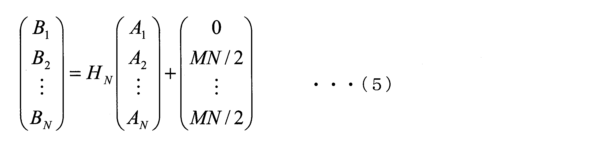
ここで、信号Ai(i=1,2,…,N)は符号化前の(M+1)値PAM信号を、信号Bi(i=1,2,…,N)は符号化後の(NM+1)値PAM信号を表す。(NM+1)値PAM信号は、異なる(NM+1)個の値のうちいずれか一つの値を示す信号である。式(5)では、従来のWalsh符号化により多値化された信号Bi(i=2,…,N)の値を、取り得る最小値が0になるように正の側にシフトする。これにより、信号Aiは{0,1,…,M}の(M+1)値のいずれか一つをとる場合、信号Biは{0,1,…,NM}の(NM+1)値のいずれか一つをとる。本実施形態の光伝送システムは、このようにして符号化した強度信号B1~BNを各チャンネルにより伝送する。以下では、強度信号Biを伝送するチャンネルを第iのチャンネルとする。行列HNはN×Nのアダマール行列であり、以下の式(6)により表される。

ここで、Nは2の累乗である。
図1は、本発明の実施形態における光伝送システム1の基本構成を示す図である。光伝送システム1は、符号化装置2及び復号化装置3を備える。符号化装置2と復号化装置3とは、光ファイバ伝送路を介して接続される。
符号化装置2は、符号化部201と、光源202-1~202-Nと、強度変調器203-1~203-Nと、波長合波器204とを備える(Nは2以上の整数)。符号化部201は、式(5)により、(M+1)値PAM信号である信号A1~ANの符号化を行い、(NM+1)値PAM信号である信号B1~BNを生成する。符号化部201は、生成された信号B1~BNを出力する。光源202-i(i=1,2,…,N)は、第iのチャンネルに用いられる波長の光を出力する。強度変調器203-i(i=1,2,…,N)は、符号化部201が出力した信号Biと、光源202-iが出力した光とを入力する。強度変調器203-iは、光源202-iが出力した光に、信号Biに基づき(NM+1)値の光振幅変調を施した強度信号を生成する。強度変調器203-iは、生成された強度信号を波長合波器204に出力する。波長合波器204は、強度変調器203-1~203-Nのそれぞれから入力した第1のチャンネル~第Nのチャンネルの強度信号B1~BNを合波した波長合成信号を、光ファイバ伝送路に出力する。
復号化装置3は、波長分波器301と、受光器302-1~302-Nと、復号化部303とを備える(Nは2以上の整数)。波長分波器301は、光ファイバ伝送路により伝送された波長合成信号を波長に基づき光信号B1~BNに分離し、第iのチャンネル(i=1,2,…,N)の光信号Biを受光器302-iに出力する。受光器302-i(i=1,2,…,N)は、波長分波器301から入力した光信号Biを直接検波し、電気信号の信号Biに変換する。受光器302-iは、電気信号に変換された信号Biを復号化部303に出力する。復号化部303は、受光器302-1~302-Nから信号B1~BNを入力する。復号化部303は、入力した信号B1~BNに対し、以下の式(7)で表される復号化処理を行うことで、符号化前の信号A1~ANを復元する。
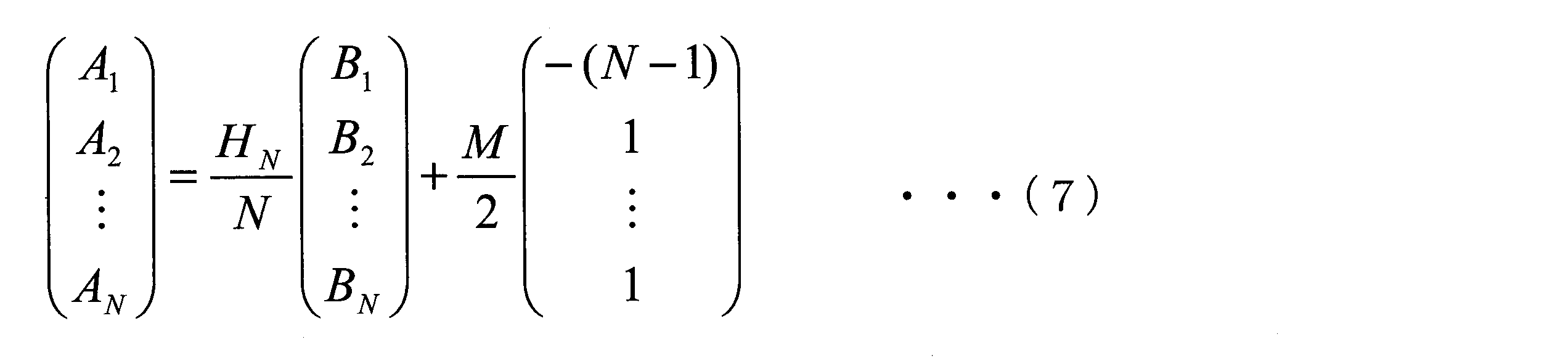
この式(7)は、式(5)を信号Aiについて解くことで得られる。
上記のように、光伝送システム1は、強度信号A1~ANを符号化し、1つの信号Aiが複数のチャンネルに分散して伝送されるように、強度信号B1~BNとして伝送する。これにより、特定のチャンネルの信号品質が波長分散や受信パワーの低下により大きく劣化した場合でも、復号化によってその品質劣化が複数のチャンネルに分散される。そのため、チャンネル間の信号品質ばらつきが平準化され、結果として光伝送システム全体の信号品質が改善される。
以下に本発明の詳細な実施形態について説明する。
以下に本発明の詳細な実施形態について説明する。
[第1の実施形態]
第1の実施形態では、2個のチャンネルのPAM4信号にWalsh符号化を行う。
図2は、第1の実施形態による光伝送システムの符号化装置21の構成を示す図である。符号化装置21は、符号化部211と、デジタル-アナログ変換器(DA変換器)212-1、212-2と、光源213-1、213-2と、強度変調器214-1、214-2と、波長合波器215とから構成される。第1の実施形態では、符号化前の信号AiはPAM4信号であり、チャンネル数は2である。
第1の実施形態では、2個のチャンネルのPAM4信号にWalsh符号化を行う。
図2は、第1の実施形態による光伝送システムの符号化装置21の構成を示す図である。符号化装置21は、符号化部211と、デジタル-アナログ変換器(DA変換器)212-1、212-2と、光源213-1、213-2と、強度変調器214-1、214-2と、波長合波器215とから構成される。第1の実施形態では、符号化前の信号AiはPAM4信号であり、チャンネル数は2である。
符号化部211は、{0,1,2,3}の4値のいずれか一つの値をとる4値のデジタルデータを示す信号A1及び信号A2に対して、式(4)で示される符号化を実行することで、{0,1,2,3,4,5,6}の7値のいずれか一つの値をとる7値のデジタルデータを示す信号B1及び信号B2を生成する。DA変換器212-i(i=1,2)は、デジタルデータの信号Biをアナログ電気信号に変換し、アナログ電気信号の信号Biを強度変調器214-iに出力する。光源213-i(i=1,2)は、第iのチャンネルの波長の光を出力する。強度変調器214-i(i=1,2)は、光源213-iから入力した光に、アナログ電気信号の信号Biにより光振幅変調を施し、第iのチャンネルの光信号に変換する。波長合波器215は、強度変調器214-1から入力した第1のチャンネルの光信号である信号B1と、強度変調器214-2から入力した第2のチャンネルの光信号である信号B2とを波長多重した波長合成信号を、光ファイバ伝送路へと送出する。
図3は、第1の実施形態による光伝送システムの復号化装置31の構成を示す図である。復号化装置31は、波長分波器311と、受光器312-1、312-2と、アナログ-デジタル変換器(AD変換器)313-1、313-2と、復号化部314とから構成される。
波長分波器311は、図2に示す符号化装置21から出力され、光ファイバ伝送路により伝送された波長合成信号を受信する。波長分波器311は、受信した波長合成信号を波長に基づき分波することによりチャンネルごとに分離し、第iのチャンネル(i=1,2)の光信号を受光器312-iに出力する。受光器312-i(i=1,2)は、第iのチャンネルの光信号をアナログ電気信号に変換し、アナログ電気信号をAD変換器313-iに出力する。AD変換器313-i(i=1,2)は、受光器312-iから入力した電気信号を{0,1,2,3,4,5,6}の7値のいずれか一つの値をとる7値のデジタルデータを示す信号Biに変換し、信号Biを復号化部314に出力する。復号化部314は、第1及び第2のチャンネルそれぞれの7値のデジタルデータを示す信号B1、B2を入力する。復号化部314は、信号B1及び信号B2に対して、以下の式(8)で示される復号化を実行することで、{0,1,2,3}の4値のいずれか一つの値をとりうる4値のデジタルデータを生成し、符号化前の信号A1及び信号A2を復元する。

この式は、式(4)を信号Aiについて解いてM=3を代入することで得られる。
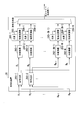
式(8)で示される復号化部314の処理は、例えば、適応デジタルフィルタを用いて実行する。適応デジタルフィルタを用いる場合の復号化部314の内部構成を図4に示す。
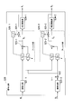
図4は、復号化部314の内部構成を示す図である。復号化部314は、フィルタh10,h11,h12,h20,h21,h22と、加算部511-1、511-2と、判定機能部512-1、512-2と、演算部513-1、513-2と、フィードバック部514-1、514-2とを備える。フィルタh10,h11,h12,h20,h21,h22は、適応デジタルフィルタである。
復号化部314では、信号Bi(i=1,2)に適応デジタルフィルタ処理を適用することで得られるデジタルデータCi(i=1,2)に対して、判定機能部314-iが閾値判定を行うことで、{0,1,2,3}の4値のいずれか一つの値をとる4値デジタルデータを示す信号Ai(i=1,2)を得る。同図におけるフィルタh10,h11,h12,h20,h21,h22を任意のタップ数のFIRフィルタとすると、加算部511-i(i=1,2)から出力されるデジタルデータCiについて、以下の式(9)及び式(10)に示す関係式が得られる。


式(9)及び式(10)における右辺第1項で定数値に対する適応フィルタ処理を適用している点が、従来のWalsh復号化と大きく異なる点であり、強度変調信号に対してWalsh復号化を適用する際に必須となる処理である。
フィードバック部514-1、514-2によるタップ係数の更新方法は、任意の方法が適用可能である。例えば、タップ係数の更新にDecision-Directed Least-Mean-Square(DD-LMS)を用いる場合は、フィルタh10,h11,h12のタップ更新に用いる誤差関数E1と、フィルタh20,h21,h22のタップ更新に用いる誤差関数E2とをそれぞれ、以下の式(11)、式(12)のように定義する。


上記の誤差関数Ei(i=1,2)は、演算部513-iが算出したAi-Ciに基づいて、フィードバック部514-iにより算出される。
フィルタhij(i=1,2,j=0,1,2)におけるタップ係数hijの更新量をΔhijとすると、フィードバック部514-1、514-2において算出される更新量Δhijは、以下の式(13)~式(15)で表される。


ここで、μはステップサイズパラメータである。フィルタhij(i=1,2,j=0,1,2)におけるタップ係数hijは適応的に変化する値であり、適応処理により式(8)の復号化を実現する。したがって、式(8)にならって、タップ係数hij(i=1,2,j=0,1,2)の初期値を以下の式(16)、式(17)の通りとしておくことで、高い収束性を持つ適応処理が可能となる。


図5は、第1の実施形態による光伝送システムの信号品質を示す図である。同図は、2個のチャンネルのPAM4信号に対して第1の実施形態を適用した際の、第2のチャンネル(CH2)の受信パワー、及び、第1のチャンネル(CH1)のビット誤り率(BER:Bit Error Rate)と第2のチャンネル(CH2)のBERの平均値の関係を示す図である。同図は数値シミュレーションの結果に基づく。ここでは、システム全体の信号品質を表す指標として、各チャンネルのBERの平均値を用いている。
図6は、図5のシミュレーションにおいて用いた各チャンネルの受信パワー及び波長分散を示す図である。同図に示すように、ここでは各チャンネルが112Gbpsのデータ伝送を実現するPAM4信号であり、チャンネル数は10である。最長波長のチャンネルを第1のチャンネル(CH1)とし、第1のチャンネルの波長は伝送ファイバのゼロ分散波長と等しいものとしている。第1のチャンネルの受信パワーを-3dBmとしている。最短波長のチャンネルを第2のチャンネル(CH2)とし、第2のチャンネルにおける累積波長分散(CD)値を0ps/nm又は64ps/nmとしている。累積波長分散値64ps/nmは、シングルモードファイバをおおよそ10km程度伝送させた場合の累積波長分散値に相当する。第1のチャンネルのPAM4信号と第2のチャンネルのPAM4信号に、第1の実施形態で示した符号化を適用する。
前述の図5は、図6に示す第1のチャンネル(CH1)と第2のチャンネル(CH2)とに第1の実施形態の符号化を適用した場合としない場合それぞれに対して、第2のチャンネルの受信パワーを変化させた際の平均BERを示している。ここで、図5において、PAM4はWalsh符号化を適用していない場合、WCPは第1の実施形態の符号化を適用している場合を表している。同図に示すように、第2のチャンネルの累積分散値が0ps/nmの場合は、符号化の適用有無によらず、同等の信号品質となっている。一方、第2のチャンネルの累積分散値が64ps/nmの場合に注目すると、本実施形態の符号化を適用しない場合、すなわち従来のPAM4信号を伝送させた場合は、第2のチャンネルの受信パワーが-6dBm以上でなければ誤り訂正限界(FEC limit)以下のBERを実現することができない。しかし、本実施形態の符号化を適用することで、第2のチャンネルの受信パワーが-12dBmであっても、FEC limit以下のBERを実現することが可能となる。これは、本実施形態の符号化を適用することで、受信パワーに換算して6dB以上の特性改善が得られたことを意味する。ここでは、適応デジタルフィルタのタップ数を31としている。
[第2の実施形態]
第2の実施形態は、2個のチャンネルのPAM4信号にWalsh符号化を行う点では第1の実施形態と同様であるが、復号化部のフィルタ構成が異なる。すなわち、第2の実施形態は、第1の実施形態の復号化部を改良することで、復号化部を構成する適応デジタルフィルタの数を削減することを特徴とする。符号化されたPAM4信号は、式(8)により復号化されるが、式(8)は以下の式(18)のように変形することができる。
第2の実施形態は、2個のチャンネルのPAM4信号にWalsh符号化を行う点では第1の実施形態と同様であるが、復号化部のフィルタ構成が異なる。すなわち、第2の実施形態は、第1の実施形態の復号化部を改良することで、復号化部を構成する適応デジタルフィルタの数を削減することを特徴とする。符号化されたPAM4信号は、式(8)により復号化されるが、式(8)は以下の式(18)のように変形することができる。

式(18)で表される処理を、適応デジタルフィルタを用いて実行することで、復号化を行うことが可能である。
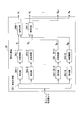
図7は、第2の実施形態による復号化部520の内部構成を示す図である。復号化部520は、図3に示す第1の実施形態の復号化部314に代えて用いられる。復号化部520は、規格化部521-1、521-2と、加算部522と、フィルタh11,h12,h21,h22と、加算部523-1、523-2と、判定機能部524-1、524-2と、演算部525-1、525-2と、フィードバック部526-1、526-2とを備える。フィルタh11,h12,h21,h22は、適応デジタルフィルタである。
第2の実施形態の規格化部521-i(i=1,2)は、受信信号Biに対して、その受信信号Biの平均値が3となるように規格化を行う。規格化後のデジタルデータを改めてBi(i=1,2)とし、加算部522は、受信信号B2に-3を加算する。判定機能部524-iが、適応デジタルフィルタ処理を適用することで得られるデジタルデータCi(i=1,2)に対して閾値判定を行うことで、{0,1,2,3}の4値のいずれか一つの値をとる4値デジタルデータを示す信号Ai(i=1,2)を得る。図中の、フィルタh11,h12,h21,h22を任意のタップ数のFIRフィルタとすると、加算部523-i(i=1,2)から出力されるデジタルデータCiについて、以下の式(19)及び式(20)に示す関係式が得られる。


フィードバック部526-1、526-2によるタップ係数の更新方法は、任意の方法が適用可能である。例えば、タップ係数の更新にDecision-Directed Least-Mean-Square(DD-LMS)を用いる場合は、タップ係数h11,h12の更新に用いる誤差関数E1と、タップ係数h21,h22の更新に用いる誤差関数E2とをそれぞれ、以下の式(21)、式(22)のように定義する。


上記の誤差関数Ei(i=1,2)は、演算部525-iが算出したAi-Ciに基づいて、フィードバック部526-iにより算出される。
フィルタhij(i,j=1,2)におけるタップ係数hijの更新量をΔhijとすると、フィードバック部526-1、526-2において算出される更新量Δhijは以下の式(23)及び式(24)で表される。


ここで、μはステップサイズパラメータである。フィルタhij(i,j=1,2)におけるタップ係数hijは適応的に変化する値であり、適応処理により式(18)の復号化を実現する。したがって、式(18)にならって、タップ係数hij(i,j=1,2)の初期値を以下の式(25)の通りとしておくことで、高い収束性を持つ適応処理が可能となる。

第1の実施形態では適応デジタルフィルタが、h10,h11,h12,h20,h21,h22の6つであったのに対し、第2の実施形態では、適応デジタルフィルタの数をh11,h12,h21,h22の4つに削減していることが特徴である。適応デジタルフィルタの数が削減されることで、復号化部520のデジタル回路の規模を縮小することが可能となる。
[第3の実施形態]
第3の実施形態では、N個のチャンネルの(M+1)値PAM信号にWalsh符号化を行う。
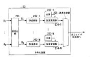
図8は、第3の実施形態による光伝送システムの符号化装置23の構成を示す図である。符号化装置23は、符号化部231と、デジタル-アナログ変換器(DA変換器)232-1~232-Nと、光源233-1~233-Nと、強度変調器234-1~234-Nと、波長合波器235とから構成される。第3の実施形態では、符号化前の信号Ai(i=1,2,…,N)は、(M+1)値PAM信号であり、チャンネル数はNである。
第3の実施形態では、N個のチャンネルの(M+1)値PAM信号にWalsh符号化を行う。
図8は、第3の実施形態による光伝送システムの符号化装置23の構成を示す図である。符号化装置23は、符号化部231と、デジタル-アナログ変換器(DA変換器)232-1~232-Nと、光源233-1~233-Nと、強度変調器234-1~234-Nと、波長合波器235とから構成される。第3の実施形態では、符号化前の信号Ai(i=1,2,…,N)は、(M+1)値PAM信号であり、チャンネル数はNである。
符号化部231は、{0,1,…,M}の(M+1)値のいずれか一つの値をとる(M+1)値のデジタルデータを示す信号A1~ANに対して、式(5)で示される符号化を実行することで、{0,1,…,NM}の(NM+1)値のいずれか一つの値をとる(NM+1)値のデジタルデータを示す信号B1~BNを生成する。DA変換器232-i(i=1,2,…,N)は、デジタルデータの信号Biをアナログ電気信号に変換し、アナログ電気信号の信号Biを強度変調器234-iに出力する。光源233-i(i=1,2,…,N)は、第iのチャンネルの波長の光を出力する。強度変調器234-i(i=1,2,…,N)は、光源233-iから入力した光に、アナログ電気信号の信号Biにより光振幅変調を施し、第iのチャンネルの光信号に変換する。波長合波器235は、強度変調器234-1~234-Nのそれぞれから入力した第1~第Nのチャンネルの光信号である信号B1~BNを波長多重し、波長多重により生成された波長合成信号を光ファイバ伝送路へと送出する。
図9は、第3の実施形態による光伝送システムの復号化装置33の構成を示す図である。復号化装置33は、波長分波器331と、受光器332-1~332-Nと、アナログ-デジタル変換器(AD変換器)333-1~333-Nと、復号化部334とから構成される。
波長分波器331は、図8に示す符号化装置23から出力され、光ファイバ伝送路により伝送された波長合成信号を受信する。波長分波器331は、受信した波長合成信号を波長に基づき分波することによりチャンネルごとに分離し、第iのチャンネル(i=1,2,…,N)の光信号をそれぞれ受光器332-iに出力する。受光器332-i(i=1,2,…,N)は、第iのチャンネルの光信号をアナログ電気信号に変換し、アナログ電気信号をAD変換器333-iに出力する。AD変換器333-i(i=1,2,…,N)は、受光器332-iから入力したアナログ電気信号を{0,1,…,NM}のいずれか一つの値をとる(NM+1)値のデジタルデータを示す信号Biに変換し、信号Biを復号化部334に出力する。復号化部334は、第1~第Nのチャンネルそれぞれの(NM+1)値のデジタルデータを示す信号B1~BNを入力する。復号化部334は、信号B1~BNに対して、以下の式(26)で示される復号化を実行することで、{0,1,…,M}のいずれか一つの値をとる(M+1)値のデジタルデータを生成し、符号化前の信号Ai(i=1,2,…,N)を復元する。
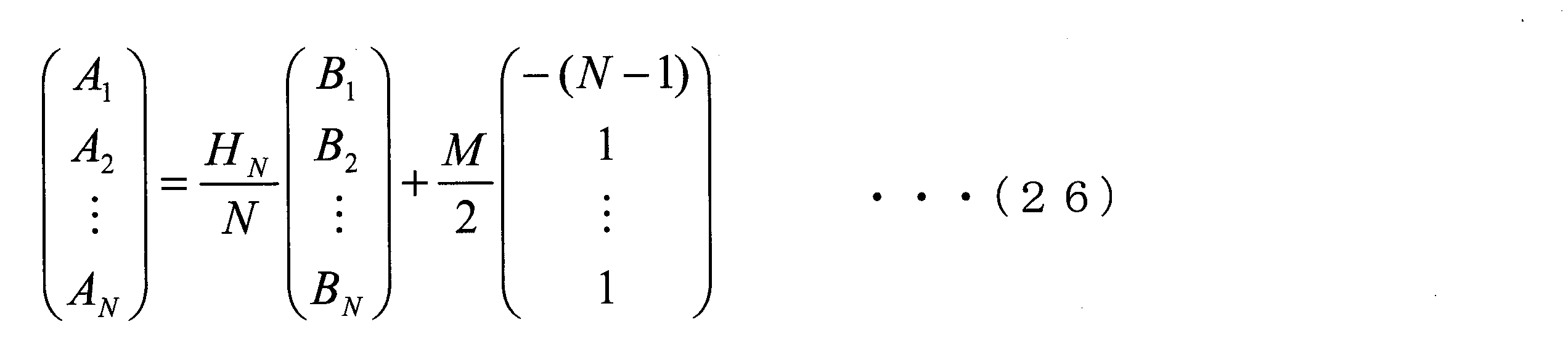
この式は、式(5)を信号Aiについて解くことで得られる。
式(26)で示される復号化部334の処理は、例えば、適応デジタルフィルタを用いて実行する。適応デジタルフィルタを用いる場合の復号化部334の内部構成を図10に示す。
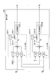
図10は、復号化部334の内部構成を示す図である。復号化部334は、フィルタh10~h1N,…,hN0~hNNと、加算部531-1~531-Nと、判定機能部532-1~532-Nと、演算部533-1~533-Nと、フィードバック部534-1~534-Nとを備える。フィルタh10~h1N,…,hN0~hNNは、適応デジタルフィルタである。
復号化部334では、信号Bi(i=1,2,…,N)に適応デジタルフィルタ処理を適用することで得られるデジタルデータCi(i=1,2,…,N)に対して、判定機能部532-iが閾値判定を行うことで、{0,1,…,M}のいずれか一つの値をとる(M+1)値デジタルデータを示す信号Ai(i=1,2,…,N)を得る。同図におけるフィルタhij(i=1,2,…,N,j=0,1,…,N)を任意のタップ数のFIRフィルタとすると、加算部531-i(i=1,2,…,N)から出力されるデジタルデータCiについて、以下の式(27)及び式(28)に示す関係式が得られる。


式(27)及び式(28)における右辺第1項で定数値に対する適応フィルタ処理を適用している点が、従来のWalsh復号化と大きく異なる点であり、強度変調信号に対してWalsh復号化を適用する際に必須となる処理である。
フィードバック部534-1~534-Nによるタップ係数の更新方法は、任意の方法が適用可能である。例えば、タップ係数の更新にDecision-Directed Least-Mean-Square(DD-LMS)を用いる場合は、フィルタhij(i=1,2,…,N,j=0,1,…,N)のタップ更新に用いる誤差関数Eiを以下の式(29)のように定義する。

上記の誤差関数Ei(i=1,2,…,N)は、演算部533-iが算出したAi-Ciに基づいて、フィードバック部534-iにより算出される。
フィルタhij(i=1,2,…,N,j=0,1,…,N)におけるタップ係数hijの更新量をΔhijとすると、フィードバック部534-1~534-Nにおいて算出される更新量Δhijは、以下の式(30)~式(32)で表される。



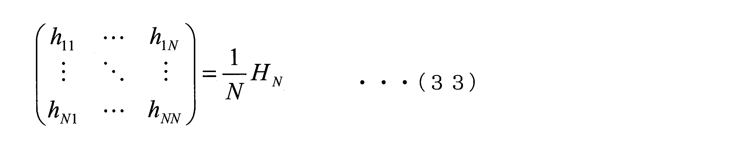
ここで、μはステップサイズパラメータである。フィルタhij(i=1,2,…,N,j=0,1,…,N)におけるタップ係数hijは適応的に変化する値であり、適応処理により式(26)の復号化を実現する。したがって、式(26)にならって、タップ係数hij(i=1,2,…,N,j=0,1,…,N)の初期値を以下の式(33)、式(34)の通りとしておくことで、高い収束性を持つ適応処理が可能となる。

[第4の実施形態]
第4の実施形態は、N個のチャンネルの(M+1)値PAM信号にWalsh符号化を行う点では第3の実施形態と同様であるが、復号化部のフィルタ構成が異なる。すなわち、第4の実施形態は、第3の実施形態の復号化部を改良することで、復号化部を構成する適応デジタルフィルタの数を削減することを特徴とする。符号化された(M+1)値PAM信号は、式(26)により復号化されるが、式(26)は以下の式(35)のように変形することができる。
第4の実施形態は、N個のチャンネルの(M+1)値PAM信号にWalsh符号化を行う点では第3の実施形態と同様であるが、復号化部のフィルタ構成が異なる。すなわち、第4の実施形態は、第3の実施形態の復号化部を改良することで、復号化部を構成する適応デジタルフィルタの数を削減することを特徴とする。符号化された(M+1)値PAM信号は、式(26)により復号化されるが、式(26)は以下の式(35)のように変形することができる。
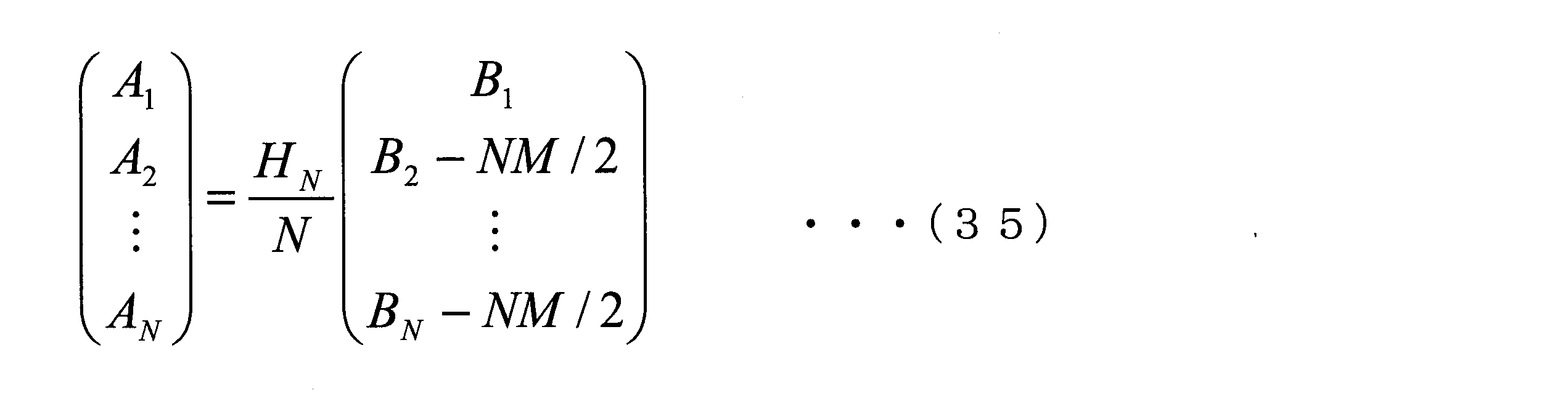
この式で表される処理を、適応デジタルフィルタを用いて実行することで、復号化を行うことが可能である。
図11は、第4の実施形態による復号化部540の内部構成を示す図である。復号化部540は、図10に示す第3の実施形態の復号化部334に代えて用いられる。復号化部540は、規格化部541-1~541-Nと、加算部542-2~542-Nと、フィルタh11~h1N,…,hN1~hNNと、加算部543-1~543-Nと、判定機能部544-1~544-Nと、演算部545-1~545-Nと、フィードバック部546-1~546-Nとを備える。フィルタh11~h1N,…,hN1~hNNは、適応デジタルフィルタである。
本実施形態の規格化部541-i(i=1,…,N)は、受信信号Biに対して、その受信信号Biの平均値がMとなるように規格化を行う。規格化後のデジタルデータを改めて信号Bi(i=1,…,N)とし、加算部542-i(i=2,…,N)は、受信信号Biに(-NM/2)を加算する。判定機能部544-iが、適応デジタルフィルタ処理を適用することで得られるCi(i=1,…,N)に対して閾値判定を行うことで、{0,1,…,M}のいずれか一つの値をとる(M+1)値デジタルデータを示す信号Ai(i=1,…,N)を得る。図中の、フィルタhij(i,j=1,…,N)を任意のタップ数のFIRフィルタとすると、加算部543-i(i=1,…,N)から出力されるCiについて、以下の式(36)に示す関係式が得られる。

フィードバック部546-1~546-Nによるタップ係数の更新方法は、任意の方法が適用可能である。例えば、タップ係数の更新にDecision-Directed Least-Mean-Square(DD-LMS)を用いる場合は、タップ係数hij(i,j=1,…,N)の更新に用いる誤差関数Eiを以下の式(37)のように定義する。

上記の誤差関数Ei(i=1,…,N)は、演算部545-iが算出したAi-Ciに基づいて、フィードバック部546-iにより算出される。
フィルタhij(i,j=1,…,N)におけるタップ係数の更新量をΔhijとすると、フィードバック部546-iにおいて算出される更新量Δhijは以下の式(38)及び式(39)で表される。


ここで、μはステップサイズパラメータである。フィルタhij(i,j=1,…,N)におけるタップ係数hijは適応的に変化する値であり、適応処理により式(35)の復号化を実現する。したがって、式(35)にならって、タップ係数hij(i,j=1,…,N)の初期値を以下の式(40)の通りとしておくことで、高い収束性を持つ適応処理が可能となる。

第3の実施形態では適応デジタルフィルタが、hij(i=1,…,N,j=0,…,N)のN(N+1)個であったのに対し、第4の実施形態では、適応デジタルフィルタの数をN^2個に削減していることが特徴である。適応デジタルフィルタの数が削減されることで、復号化部540のデジタル回路の規模を縮小することが可能となる。
[第5の実施形態]
第5の実施形態では、N個のチャンネルから符号化を行うチャンネルペアを選択する方法について説明する。
第5の実施形態では、N個のチャンネルから符号化を行うチャンネルペアを選択する方法について説明する。
図12は、N個のチャンネル全てに符号化を適用する場合を説明するための図である。第3の実施形態及び第4の実施形態では、同図に示すように、N個のチャンネルの(M+1)値PAM信号に対して符号化を適用した。しかし、光伝送システムがN個のチャンネルから構成されていたとしても、必ずしもすべてのチャンネルに対して第3の実施形態又は第4の実施形態による符号化を適用しなくても、信号品質の改善効果を得ることは可能である。
第1~第4の実施形態は、複数のチャンネルの信号品質を平均化する効果を持ったものである。したがって、N個のチャンネルすべてに対して符号化を適用する場合に、最も高い信号品質改善効果が得られる。しかし、N個のチャンネルすべてに対して符号化を適用する場合は、復号化の際に必要となる適応デジタルフィルタの数が、第3の実施形態ではN(N+1)個、第4の実施形態ではN^2個となる。チャンネル数の2乗のオーダで適応デジタルフィルタ数が増加するため、チャンネル数Nが大きな値の光伝送システムでは、復号化を実現するデジタル信号処理回路を実現することが回路規模の観点から難しくなる。
そこで、第5の実施形態では、図13に示すように、N個のチャンネルの(M+1)値PAM信号から、任意の2個のチャンネルを選択し、その2個のチャンネルに対して符号化を適用する。
図13は、第5の実施形態における符号化対象のチャンネルの選択を説明するための図である。このように、N個のチャンネルの(M+1)値PAM信号から選択した任意の2個のチャンネルに対して符号化を適用することで、復号化の際に必要となる適応デジタルフィルタの数を削減する。任意の2個のチャンネルの選択の仕方により、符号化により得られる信号品質改善効果の量は異なったものとなる。第1~第4の実施形態が複数のチャンネルの信号品質を平均化する効果を持っていることに着目すると、以下の手順で2個のチャンネルを選択することで、光伝送システム全体の信号品質を最大化することが可能となる。
図13は、第5の実施形態における符号化対象のチャンネルの選択を説明するための図である。このように、N個のチャンネルの(M+1)値PAM信号から選択した任意の2個のチャンネルに対して符号化を適用することで、復号化の際に必要となる適応デジタルフィルタの数を削減する。任意の2個のチャンネルの選択の仕方により、符号化により得られる信号品質改善効果の量は異なったものとなる。第1~第4の実施形態が複数のチャンネルの信号品質を平均化する効果を持っていることに着目すると、以下の手順で2個のチャンネルを選択することで、光伝送システム全体の信号品質を最大化することが可能となる。
まず、N個のチャンネルの(M+1)値PAM信号に対し、信号品質が高いものから順に、チャンネル番号を付与する。すなわち、信号品質が最大のチャンネルを第1のチャンネル、その次に高い信号品質を有するチャンネルを第2のチャンネル、とチャンネル番号を付与し、信号品質が最低のチャンネルを第Nのチャンネルとするように各チャンネルにチャンネル番号を付与する。信号品質が高い順にチャンネル番号を付与したこれらのチャンネルに対して、第1のチャンネルと第Nのチャンネルとをペアとして選択し、第2のチャンネルと第(N-1)のチャンネルをペアとして選択し、以下同様の第iのチャンネルと第(N-i+1)のチャンネルとをペアとして選択する。次に、それぞれのペアに対して個別に符号化を適用する。Nが奇数の場合は、第(N+1)/2のチャンネルはそのままの形、すなわち(M+1)値PAM信号として伝送する。信号品質を示す指標として、図13に示したように、各チャンネルの受信パワーを用いてもよいし、各チャンネルのビット誤り率又は波長分散値を用いてもよい。
図14は、第5の実施形態による光伝送システムの符号化装置26の構成を示す図である。符号化装置26は、符号化部261-1~261-Lと、デジタル-アナログ変換器(DA変換器)262-1~262-Nと、光源263-1~263-Nと、強度変調器264-1~264-Nと、波長合波器265とから構成される。Nが偶数の場合はL=N/2であり、Nが奇数の場合はL=(N-1)/2である。まず、Nが偶数の場合について説明する。
符号化部261-i(i=1,…,L)は、信号Ai及び信号AN-i+1に対して、第1の実施形態の符号化部211と同様の符号化を行い、信号Bi及び信号BN-i+1を生成する。すなわち、符号化部261-i(i=1,…,L)は、信号Ai、AN-i+1、Bi、BN-i+1をそれぞれ、式(4)における信号A1、A2、B1、B2として演算を行う。DA変換器262-i(i=1,…,N)は、デジタルデータの信号Biをアナログ電気信号に変換し、アナログ電気信号の信号Biを強度変調器264-iに出力する。光源263-i(i=1,…,N)は、第iのチャンネルの波長の光を出力する。強度変調器264-i(i=1,…,N)は、光源263-iから入力した光に、アナログ電気信号の信号Biにより光振幅変調を施し、第iのチャンネルの光信号に変換する。波長合波器265は、強度変調器264-1~264-Nそれぞれから入力した第1のチャンネル~第Nのチャンネルの光信号である信号B1~BNを波長多重し、波長多重により生成された波長合成信号を光ファイバ伝送路へと送出する。
Nが奇数の場合、符号化装置26は、信号A(N+1)/2に対して符号化を行わずにそのままDA変換器262-(N+1)/2に出力する。他の動作についてはNが偶数の場合と同じである。
図15は、第5の実施形態による光伝送システムの復号化装置36の構成を示す図である。復号化装置36は、波長分波器361と、受光器362-1~362-Nと、アナログ-デジタル変換器(AD変換器)363-1~363-Nと、復号化部364-Kとから構成される。Nが偶数の場合はK=N/2であり、Nが奇数の場合はK=(N+1)/2である。まず、Nが偶数の場合について説明する。
波長分波器361は、図14に示す符号化装置26から出力され、光ファイバ伝送路により伝送された波長合成信号を受信する。波長分波器361は、受信した光信号を波長に基づき分波することにより第1~第Nのチャンネルの光信号に分離し、第iのチャンネル(i=1,…,N)の光信号を受光器362-iに出力する。受光器362-i(i=1,…,N)は、第iのチャンネルの光信号をアナログ電気信号に変換し、アナログ電気信号をAD変換器363-iに出力する。AD変換器363-i(i=1,…,M)は、受光器362-iから入力したアナログ電気信号をデジタルデータを示す信号Biに変換する。復号化部364-i(i=1,…,K)は、AD変換器363-iが出力した信号Biと、AD変換器363-(N-i+1)が出力した信号B(N-i+1)とを入力する。復号化部364-i(i=1,…,K)は、信号Bi、B(N-i+1)に対して、第1の実施形態の復号化部314又は第2の実施形態の復号化部520と同様の処理を行い、符号化前の信号Ai、A(N-i+1)を復元する。すなわち、復号化部364-i(i=1,…,K)は、信号Bi、BN-i+1、Ai、AN-i+1をそれぞれ、式(8)又は式(18)における信号B1、B2、A1、A2として演算を行う。
Nが奇数の場合、復号化装置36の復号化部364-Kは、信号BKに対して閾値判定を行い、信号AKを復元する。閾値判定は、信号Akのとりうる(M+1)値のうち、信号Bkが示す値と最も近い値を得る処理である。例えば、復号化部364-Kは、信号Akのとりうる(M+1)値に応じて定められたM個の閾値それぞれと信号Bkが示す値とを比較し、比較結果に基づいて信号Bkが示す値と最も近い値を得てもよい。
上記のように、符号化装置26における符号化部261-i(i=1,…,L)は、図2に示す第1の実施形態における2個のチャンネルに対する符号化部211と同様の処理を行う。復号化装置36における復号化部364-i(i=1,…,K)は、2個のチャンネルに対する復号化部と同様の処理を行う。復号化部364-iの構成は、図4に示す第1の実施形態における復号化部314の構成、又は、図7に示す第2の実施形態における復号化部520の構成と同様である。第5の実施形態における復号化部364-1~364-Kの数Kは、N/2個である。第3の実施形態における復号化部で必要となる適応デジタルフィルタの数がN(N+1)個であった。これに対し、第5の実施形態において必要となる適応デジタルフィルタの数は、第1の実施形態と同様の構成の復号化部の場合、合計で3N個である。したがって、第5の実施形態の適用により、適応デジタルフィルタの数を3/(N+1)倍に削減することが可能となる。また、第4の実施形態における符号化部で必要となる適応デジタルフィルタの数がN^2個であった。これに対し、第5の実施形態において必要となる適応デジタルフィルタの数は、第2の実施形態と同様の構成の復号化部の場合、合計で2N個である。したがって、本実施形態の適用により、適応デジタルフィルタの数を2/N倍に削減することが可能となる。光伝送システムを構成するチャンネル数Nが大きければ大きいほど、適応デジタルフィルタ数の削減効果が大きい。
第5の実施形態ではN個のチャンネルのPAM信号のうち2個のPAM信号を含む(N/2)個の組ごとに符号化及び復号を行う構成を説明した。N個のチャンネルのPAM信号のうち2L個のPAM信号を含む(N/2L)個の組ごとに符号化及び復号を行ってもよい(Lは1以上の整数、2LはN以下)。2L個のPAM信号を含む(N/2L)個の組ごとに符号化を行う場合、符号化部261は、各組に含まれる2L個のPAM信号を要素とした行列と、2L行2L列のアダマール行列との内積を演算することにより、符号化を行う。符号化部261は、内積演算により得られる2L個の信号のうち、常に正の値となる信号を符号化信号として出力する。符号化部261は、内積演算により得られる2L個の信号のうち、取り得る値に負の値が含まれる信号に(2LM/2)を加算し、加算結果を符号化信号として出力する。
2L個のPAM信号を含む(N/2L)個の組ごとに符号化を行う場合、各組に含まれる2L個のPAM信号の信号品質の平均値のばらつきが最小になるように、各組に含まれる2L個のPAM信号が選択される。このように各組の2L個のPAM信号を選択することにより、各チャンネルの信号品質の劣化が平準化されるので、光伝送システム全体の信号品質が改善される。各組に含まれる2L個のPAM信号の選択は、例えば、以下のように行われる。
[第1の手順] N個のチャンネルのうち、1番目に信号品質が高いチャンネルのPAM信号が、1番目の組に含まれるPAM信号として選択される。i番目に信号品質が高いチャンネルのPAM信号が、i番目の組に含まれるPAM信号として選択される(i=2,3,…,Q;2LQ≦N)。
[第2の手順] N個のチャンネルのうち、1番目に信号品質が低いチャンネルのPAM信号が、1番目の組に含まれるPAM信号として選択される。i番目に信号品質が低いチャンネルのPAM信号が、i番目の組に含まれるPAM信号として選択される。
[第3の手順] N個のチャンネルのうち、(Q+1)番目に信号品質が高いチャンネルのPAM信号が、1番目の組に含まれるPAM信号として選択される。(Q+i)番目に信号品質が高いチャンネルのPAM信号が、i番目の組に含まれるPAM信号として選択される。
[第4の手順] N個のチャンネルのうち、(Q+1)番目に信号品質が低いチャンネルのPAM信号が、1番目の組に含まれるPAM信号として選択される。(Q+i)番目に信号品質が低いチャンネルのPAM信号が、i番目の組に含まれるPAM信号として選択される。
[第p-1の手順] N個のチャンネルのうち、(((p-2)Q+2))/2)番目に信号品質が高いチャンネルのPAM信号が、1番目の組に含まれるPAM信号として選択される(p=6,8,…,2L)。(((p-2)Q+2i))/2)番目に信号品質が高いチャンネルのPAM信号が、i番目の組に含まれるPAM信号として選択される。
[第pの手順] N個のチャンネルのうち、(((p-2)Q+2))/2)番目に信号品質が低いチャンネルのPAM信号が、1番目の組に含まれるPAM信号として選択される。(((p-2)Q+2i))/2)番目に信号品質が低いチャンネルのPAM信号がi番目の組に含まれるPAM信号として選択される。
[第2の手順] N個のチャンネルのうち、1番目に信号品質が低いチャンネルのPAM信号が、1番目の組に含まれるPAM信号として選択される。i番目に信号品質が低いチャンネルのPAM信号が、i番目の組に含まれるPAM信号として選択される。
[第3の手順] N個のチャンネルのうち、(Q+1)番目に信号品質が高いチャンネルのPAM信号が、1番目の組に含まれるPAM信号として選択される。(Q+i)番目に信号品質が高いチャンネルのPAM信号が、i番目の組に含まれるPAM信号として選択される。
[第4の手順] N個のチャンネルのうち、(Q+1)番目に信号品質が低いチャンネルのPAM信号が、1番目の組に含まれるPAM信号として選択される。(Q+i)番目に信号品質が低いチャンネルのPAM信号が、i番目の組に含まれるPAM信号として選択される。
[第p-1の手順] N個のチャンネルのうち、(((p-2)Q+2))/2)番目に信号品質が高いチャンネルのPAM信号が、1番目の組に含まれるPAM信号として選択される(p=6,8,…,2L)。(((p-2)Q+2i))/2)番目に信号品質が高いチャンネルのPAM信号が、i番目の組に含まれるPAM信号として選択される。
[第pの手順] N個のチャンネルのうち、(((p-2)Q+2))/2)番目に信号品質が低いチャンネルのPAM信号が、1番目の組に含まれるPAM信号として選択される。(((p-2)Q+2i))/2)番目に信号品質が低いチャンネルのPAM信号がi番目の組に含まれるPAM信号として選択される。
上記の第1、第2、第3、第4、第p-1及び第pの手順(p=6,8,…,2L)を行うことにより、Q個の組それぞれに含まれる2L個のPAM信号が決定される。上記の2L個のPAM信号を選択する手順は、一例であり、2L個のPAM信号の信号品質の平均値のばらつきを最小にする選択する他の手順を用いてもよい。
復号化部364は、2L個のPAM信号を含む(N/2L)個の組ごとに、信号を復号してもよい。2L個のPAM信号を含む組に対して復号を行う場合、復号化部364は、2L個のPAM信号を要素とした行列と、2L行2L列のアダマール行列との内積を演算することにより、復号を行う。復号化部364は、内積演算により得られる信号を2Lで除算して得られた信号のうち、取り得る値の範囲に負の値が含まれていない信号に(-M(2L-1)/2)を加算し、加算結果を復号結果として出力する。復号化部364は、内積演算により得られる信号を2Lで除算して得られた信号のうち、取り得る値の範囲に負の値が含まれている信号に(M/2)を加算し、加算結果を復号結果として出力する。
符号化及び復号における内積の演算負荷に応じて、各組に含まれるPAM信号数を2からNまでの範囲において決定してもよい。演算負荷に応じて各組に含まれるPAM信号数を決定することにより、演算負荷の増加を抑えつつ信号品質を改善できる。
[第6の実施形態]
第6の実施形態では、上述した実施形態の復号化部が有する適応デジタルフィルタのタップ数の算出方法について説明する。
第6の実施形態では、上述した実施形態の復号化部が有する適応デジタルフィルタのタップ数の算出方法について説明する。
図5に示したように、各実施形態では、チャンネル間の受信パワーの違いに起因した信号品質のばらつきのみならず、波長分散による波形劣化の度合いの違いに起因した信号品質ばらつきに対しても、信号品質の平準化効果を有する。波長分散による波形劣化の一部は復号化を実現する適応デジタルフィルタによって補償することが可能である。したがって、適応デジタルフィルタのタップ数は、波長分散に起因した波形劣化の補償に対して重要なパラメータとなる。
各実施形態における復号化は、伝送ファイバによる波長分散の影響を複数のチャンネルで共有する操作に相当するため、復号化を実現する適応デジタルフィルタのタップ数は、すべてのチャンネルで同一とすることが望ましい。N個のチャンネルの(M+1)値PAM信号に対して符号化を適用する場合は、N個のチャンネルの中で最も大きい波長分散を受けるチャンネルに注目する。最も大きい波長分散値に基づいて適応デジタルフィルタのタップ数を決定することで、より大きな信号品質改善効果が得られる。
N個のチャンネルの中で最も大きい波長分散を受けるチャンネルを第dのチャンネルとし、第dのチャンネルが受ける累積波長分散をD[ps/nm]とする。(M+1)値PAM信号の変調速度をF[Gbaud(ギガボー)]とすると、シンボル周期は1000/F[ps]となる。また、信号スペクトルの帯域幅はおおよそF[GHz]となる。一方、波長分散D[ps/nm]によって第dのチャンネルに発生する光波形広がりは、おおよそDF/125[ps]であり、これはDF2/125000シンボル分の波形広がりに相当する。
例えば、累積波長分散が64ps/nmであり、信号の変調速度が56Gbaudの場合、波長分散による波形広がりはおよそ29psとなる。これは、およそ2シンボル分の波形広がりに相当する。すなわち、2シンボル分の同期ずれが発生する可能性がある。一般的に、適応デジタルフィルタのタップは信号のシンボル周期Tに対して、T/2の間隔で実装される。したがって、この例では、タップ数(タップ長)は4以上とすることにより、波長分散の影響を低減させることができる。タップ数を2以上とする場合、タップ係数hijを示すベクトルの更新は、式(13)~(15)、(23)、(24)、(30)~(32)、(38)、(39)における信号Ai、Bi、Ciをタップ数と同じ長さの時系列(ベクトル)を用いて行われる。
以上説明した実施形態によれば、符号化装置は、符号化部と、波長合成部と、N個のチャンネルそれぞれに対応するN個のデジタルアナログ変換部、N個の光源及びN個の光強度変調部とを備える。N個のデジタルアナログ変換部は、例えば、DA変換器212-1、212-2、232-1~232-Nである。N個の光強度変調部は、例えば、強度変調器214-1、214-2、234-1~234-Nである。波長合波部は、例えば、波長合波器215、235である。符号化部は、(M+1)値(Mは1以上の整数)のN個(Nは2以上の整数)の強度信号を入力する。符号化部は、N行N列のアダマール行列とN個の強度信号を要素とする行列との内積を算出して得られた(NM+1)値のN個のチャンネルの符号化信号のうち取り得る値の範囲の最小値が負の符号化信号に、取り得る最小値が0となるように定数(NM/2)を加算する符号化処理を行う。符号化処理は、例えば、式(5)で示され、N=2、M=3のときは、例えば、式(8)で示される。N個のデジタルアナログ変換部は、対応するチャンネルの符号化信号を、デジタル信号から電気のアナログ信号に変換する。N個の光源は、対応するチャンネルに用いられる波長の光を出力する。N個の光強度変調部は、対応するチャンネルの光源から出力された光を、対応するチャンネルのデジタルアナログ変換部により電気のアナログ信号に変換された符号化信号により強度変調する。波長合波部は、N個の光強度変調部それぞれにより強度変調された光を波長多重した波長合成信号を出力する。
復号化装置は、波長分波部と、復号化部と、N個のチャンネルごとに設けられたN個の受光部及びN個のアナログデジタル変換部とを備える。波長分波部は、例えば、波長分波器311、331である。N個の受光部は、例えば、受光器312-1、312-2、332-1~332-Nである。N個のアナログデジタル変換部は、例えば、AD変換器313-1、313-2、333-1~333-Nである。波長分波部は、受信した波長多重信号を波長に基づきN個のチャンネルの光信号に分波する。N個の受光部は、波長分波部により分波されたN個のチャンネルの光信号のうち自機能部に対応するチャンネルの光信号を(NM+1)値の電気信号である強度信号に変換する。N個のアナログデジタル変換部は、対応するチャンネルの強度信号をアナログ信号からデジタル信号に変換する。復号化部は、復号化信号を得る復号化処理を行う。復号化処理では、復号化部は、N行N列のアダマール行列と、N個のアナログデジタル変換部によりデジタル信号に変換された強度信号を要素とする行列との内積をNで除算する。符号化部は、除算結果として得られた復号化信号のうち、取り得る値の範囲の最小値が正の復号化信号には、取り得る最小値が0となるように定数(-M(N-1)/2)を加算し、取り得る値の範囲の最小値が負の復号化信号には、取り得る最小値が0となるように定数(M/2)を加算する。符号化部は、N個の加算結果をN個の(M+1)値の復号化信号として得る。この復号化処理は、例えば、式(7)で示され、N=2、M=3の場合は、式(8)で示される。
復号化部は、N個のチャンネルにそれぞれ対応し(N+1)個の適応デジタルフィルタを有するN個のフィルタ部と、N個のチャンネルにそれぞれ対応する判定機能部とを備えてもよい。N個のチャンネルのうちi番目(iは1以上N以下の整数)のチャンネルの強度信号をBi、N個のフィルタ部のうちi番目のチャンネルに対応したフィルタ部が有する(N+1)個の適応デジタルフィルタのうちj番目(jは0以上N以下の整数)の適応デジタルフィルタのタップ係数をhij、i番目のチャンネルに対応したフィルタ部による処理後のデジタルデータをCi、N行N列のアダマール行列をHNとする。i番目のチャンネルに対応したフィルタ部は、式(27)及び式(28)によりデジタルデータCiを算出する。例えば、N=2、M=3の場合、フィルタ部は、式(9)及び式(10)によりデジタルデータCiを算出する。N個の判定機能部のうちi番目のチャンネルに対応した判定機能部は、デジタルデータCiに閾値判定を行って信号を復号する。タップ係数hijの初期値は、式(33)及び式(34)で示される。例えば、N=2、M=3の場合、タップ係数hijの初期値は、式(16)及び式(17)で示される。
あるいは、復号化部は、N個のチャンネルにそれぞれ対応しN個の適応デジタルフィルタを有するN個のフィルタ部と、N個のチャンネルにそれぞれ対応する判定機能部とを備えてもよい。N個のチャンネルのうちi番目(iは1以上N以下の整数)のチャンネルの強度信号をBi、N個のフィルタ部のうちi番目のチャンネルに対応したフィルタ部が有するN個の適応デジタルフィルタのうちj番目(jは1以上N以下の整数)の適応デジタルフィルタのタップ係数をhij、i番目のチャンネルに対応したフィルタ部による処理後のデジタルデータをCi、N行N列のアダマール行列をHNとする。i番目のチャンネルに対応したフィルタ部は、式(36)によりデジタルデータCiを算出する。例えば、N=2、M=3の場合、フィルタ部は、式(19)及び式(20)によりデジタルデータCiを算出する。N個の判定機能部のうちi番目のチャンネルに対応した判定機能部は、デジタルデータCiに閾値判定を行って信号を復号する。タップ係数hijの初期値は、式(40)で示され、例えば、N=2の場合、タップ係数hijの初期値は、式(25)で示される。
複数の適応デジタルフィルタは、所定より波長分散が大きなチャンネルの波長分散値に基づいて決定された同一のタップ数を用いてもよい。例えば、全ての適応デジタルフィルタのタップ数は、使用されるN個のチャンネルの中で波長分散が最も大きなチャンネルの波長分散値に基づいて決定されてもよい。
あるいは、符号化装置の符号化部は、符号化処理を行うことにより、N個のチャンネルの符号化信号を生成する。符号化処理において、符号化部は、(M+1)値(Mは1以上の整数)のN個(Nは2以上の整数)の強度信号を入力し、2L(Lは1以上の整数、2LはN以下)個の強度信号の組ごとに、2L行2L列のアダマール行列と組に含まれる2L個の強度信号を要素とする行列との内積を算出する。符号化部は、内積を算出して得られた(2LM+1)値の2L個のチャンネルの符号化信号のうち、取り得る値の範囲の最小値が負である符号化信号に、取り得る最小値が0となるように定数(2LM/2)を加算する。符号化部は、加算結果の符号化信号と、内積を算出して得られた(2LM+1)値の2L個のチャンネルの符号化信号のうち取り得る値の範囲が正の値である符号化信号とを、N個のチャンネルの符号化信号として出力する。符号化部は、例えば、符号化部261-1~261-Lであり、符号化処理は、例えば、式(4)で示される。各組は、信号品質がi番目(iは1以上N/2以下の整数)に高い強度信号と、信号品質がi番目に低い強度信号とにより構成されてもよい。
符号化装置が、2L個の強度信号の組ごとに符号化処理を行う場合、符号化装置の復号化部は、以下の復号化処理を行う。復号化部は、N個のアナログデジタル変換部のそれぞれによりデジタル信号に変換されたN個のチャンネルの強度信号における2L個の強度信号の組ごとに、2L行2L列のアダマール行列と、一つの組に含まれる2L個の強度信号を要素とする行列との内積を2Lで除算する。復号化部は、除算して得られた復号化信号のうち、取り得る値の範囲の最小値が正の復号化信号には、取り得る最小値が0となるように定数(-M(2L-1)/2)を加算し、取り得る値の範囲の最小値が負の復号化信号には、取り得る最小値が0となるように定数(M/2)を加算する。復号化部は、N個の加算結果を、復号化処理の結果として出力する。復号化部は、例えば、復号化部364-1~364-Kであり、復号化処理は、例えば、N=2の場合の式(7)で示され、例えば、M=3の場合は、式(8)で示される。
上述した実施形態によれば、多チャンネル光伝送システムにおいて強度変調信号を伝送する複数のチャンネルから適切なチャンネルの組を抽出し、そのチャンネルの組に対してWalsh符号化を適用することで、チャンネル間の信号品質ばらつきを平準化し、光伝送システム全体の信号品質を改善することができる。
上述した実施形態における符号化装置2、21、23、26、及び、復号化装置3、31、33、36の一部の機能をコンピュータで実現するようにしてもよい。その場合、この機能を実現するためのプログラムをコンピュータ読み取り可能な記録媒体に記録して、この記録媒体に記録されたプログラムをコンピュータシステムに読み込ませ、実行することによって実現してもよい。前述した機能を実現するためのプログラムを、ネットワークを通して提供することも可能である。ここでいう「コンピュータシステム」とは、OSや周辺機器等のハードウェアを含むものとする。「コンピュータ読み取り可能な記録媒体」とは、フレキシブルディスク、光磁気ディスク、ROM、CD-ROM等の可搬媒体、コンピュータシステムに内蔵されるハードディスク等の記憶装置のことをいう。さらに「コンピュータ読み取り可能な記録媒体」とは、インターネット等のネットワークや電話回線等の通信回線を介してプログラムを送信する場合の通信線のように、短時間の間、動的にプログラムを保持するもの、その場合のサーバやクライアントとなるコンピュータシステム内部の揮発性メモリのように、一定時間プログラムを保持しているものも含んでもよい。上記プログラムは、前述した機能の一部を実現するためのものであってもよく、さらに前述した機能をコンピュータシステムにすでに記録されているプログラムとの組み合わせで実現できるものであってもよい。
以上、この発明の実施形態について図面を参照して詳述してきたが、具体的な構成はこの実施形態に限られるものではなく、この発明の要旨を逸脱しない範囲の設計等も含まれる。
波長多重された光信号を送受信する光伝送システムに適用可能である。
1…光伝送システム
2、21、23、26…符号化装置
3、31、33、36…復号化装置
201…符号化部
202-1~202-N…光源
203-1~203-N…強度変調器
204…波長合波器
211…符号化部
212-1、212-2…DA変換器
213-1、213-2…光源
214-1、214-2…強度変調器
215…波長合波器
231…符号化部
232-1~232-N…DA変換器
233-1~233-N…光源
234-1~234-N…強度変調器
235…波長合波器
261-1、261-2…符号化部
262-1~262-N…DA変換器
263-1~263-N…光源
264-1~264-N…強度変調器
265…波長合波器
301…波長分波器
302-1~302-N…受光器
303…復号化部
311…波長分波器
312-1、312-2…受光器
313-1、313-2…AD変換器
314…復号化部
331…波長分波器
332-1~332-N…受光器
333-1~333-N…AD変換器
334…復号化部
361…波長分波器
362-1~362-N…受光器
363-1~363-N…AD変換器
364-1、364-2…復号化部
511-1、511-2…加算部
512-1、512-2…判定機能部
513-1、513-2…演算部
514-1、514-2…フィードバック部
520…復号化部
521-1、521-2…規格化部
522…加算部
523-1、523-2…加算部
524-1、524-2…判定機能部
525-1、525-2…演算部
526-1、526-2…フィードバック部
531-1~531-N…加算部
532-1~532-N…判定機能部
533-1~533-N…演算部
534-1~534-N…フィードバック部
540…復号化部
541-1~541-N…規格化部
542-N…加算部
543-1~543-N…加算部
544-1~544-N…判定機能部
545-1~545-N…演算部
546-1~546-N…フィードバック部
h10~hNN…適応デジタルフィルタ
2、21、23、26…符号化装置
3、31、33、36…復号化装置
201…符号化部
202-1~202-N…光源
203-1~203-N…強度変調器
204…波長合波器
211…符号化部
212-1、212-2…DA変換器
213-1、213-2…光源
214-1、214-2…強度変調器
215…波長合波器
231…符号化部
232-1~232-N…DA変換器
233-1~233-N…光源
234-1~234-N…強度変調器
235…波長合波器
261-1、261-2…符号化部
262-1~262-N…DA変換器
263-1~263-N…光源
264-1~264-N…強度変調器
265…波長合波器
301…波長分波器
302-1~302-N…受光器
303…復号化部
311…波長分波器
312-1、312-2…受光器
313-1、313-2…AD変換器
314…復号化部
331…波長分波器
332-1~332-N…受光器
333-1~333-N…AD変換器
334…復号化部
361…波長分波器
362-1~362-N…受光器
363-1~363-N…AD変換器
364-1、364-2…復号化部
511-1、511-2…加算部
512-1、512-2…判定機能部
513-1、513-2…演算部
514-1、514-2…フィードバック部
520…復号化部
521-1、521-2…規格化部
522…加算部
523-1、523-2…加算部
524-1、524-2…判定機能部
525-1、525-2…演算部
526-1、526-2…フィードバック部
531-1~531-N…加算部
532-1~532-N…判定機能部
533-1~533-N…演算部
534-1~534-N…フィードバック部
540…復号化部
541-1~541-N…規格化部
542-N…加算部
543-1~543-N…加算部
544-1~544-N…判定機能部
545-1~545-N…演算部
546-1~546-N…フィードバック部
h10~hNN…適応デジタルフィルタ
Claims (9)
- M+1値(Mは1以上の整数)のN個(Nは2以上の整数)の強度信号を入力し、N行N列のアダマール行列とN個の前記強度信号を要素とする行列との内積を算出して得られた(NM+1)値のN個のチャンネルの符号化信号のうち取り得る値の範囲の最小値が負の前記符号化信号に(NM/2)を加算する符号化処理を行う符号化部と、
前記N個のチャンネルにそれぞれ対応し、対応するチャンネルの前記符号化信号を、デジタル信号から電気のアナログ信号に変換するN個のデジタルアナログ変換部と、
前記N個のチャンネルにそれぞれ対応し、対応するチャンネルに用いられる波長の光を出力するN個の光源と、
前記N個のチャンネルにそれぞれ対応し、前記N個の光源から出力された前記光を、前記N個のデジタルアナログ変換部により電気のアナログ信号に変換された前記符号化信号によりそれぞれ強度変調するN個の光強度変調部と、
前記N個の光強度変調部により強度変調された前記光を波長多重した波長合成信号を出力する波長合波部と、
を備える符号化装置。 - M+1値(Mは1以上の整数)のN個(Nは2以上の整数)の強度信号を入力し、2L(Lは1以上の整数、2LはN以下)個の前記強度信号の組ごとに、2L行2L列のアダマール行列と前記組に含まれる2L個の前記強度信号を要素とする行列との内積を算出して得られた(2LM+1)値の2L個のチャンネルの符号化信号のうち取り得る値の範囲の最小値が負である前記符号化信号に(2LM/2)を加算する符号化処理を行い、N個のチャンネルの前記符号化信号を生成する符号化部と、
前記N個のチャンネルにそれぞれ対応し、対応するチャンネルの前記符号化信号を、デジタル信号から電気のアナログ信号に変換するN個のデジタルアナログ変換部と、
前記N個のチャンネルにそれぞれ対応し、対応するチャンネルに用いられる波長の光を出力するN個の光源と、
前記N個のチャンネルにそれぞれ対応し、前記N個の光源から出力された前記光を、前記N個のデジタルアナログ変換部により電気のアナログ信号に変換された前記符号化信号によりそれぞれ強度変調するN個の光強度変調部と、
前記N個の光強度変調部により強度変調された前記光を波長多重した波長合成信号を出力する波長合波部と、
を備える符号化装置。 - 前記強度信号の組それぞれに含まれる2L個の前記強度信号は、前記強度信号の組それぞれに含まれる2L個の前記強度信号の信号品質の平均値のばらつきが最小となるように選択される、
請求項2に記載の符号化装置。 - L=1の場合、前記強度信号の組のうちi(iは1以上N/2以下の整数)番目の組は、前記N個の強度信号のうち、信号品質がi番目に高い前記強度信号と、信号品質がi番目に低い前記強度信号とにより構成される、
請求項2に記載の符号化装置。 - 受信した波長多重信号を波長に基づきN個のチャンネルの光信号に分波する波長分波部と、
前記N個のチャンネルにそれぞれ対応し、前記波長分波部により分波された前記N個のチャンネルの前記光信号のうち対応するチャンネルの前記光信号を(NM+1)値(Mは1以上の整数)の電気信号である強度信号に変換するN個の受光部と、
前記N個のチャンネルにそれぞれ対応し、対応するチャンネルの前記強度信号をアナログ信号からデジタル信号に変換するN個のアナログデジタル変換部と、
N行N列のアダマール行列と、前記N個のアナログデジタル変換部によりデジタル信号に変換された前記強度信号を要素とする行列との内積をNで除算して得られた復号化信号のうち、取り得る値の範囲の最小値が正の前記復号化信号には(-M(N-1)/2)を加算し、取り得る値の範囲の最小値が負の前記復号化信号には(M/2)を加算してN個の(M+1)値の復号化信号を得る復号化処理を行う復号化部と、
を備える復号化装置。 - 前記復号化部は、
前記N個のチャンネルにそれぞれ対応し、(N+1)個の適応デジタルフィルタを有するN個のフィルタ部と、
前記N個のチャンネルにそれぞれ対応するN個の判定機能部と、
を備え、
前記N個のチャンネルのうちi番目(iは1以上N以下の整数)のチャンネルの前記強度信号をBiで表し、
前記N個のフィルタ部のうち前記i番目のチャンネルに対応したフィルタ部が有する前記(N+1)個の適応デジタルフィルタのうちj番目(jは0以上N以下の整数)の適応デジタルフィルタのタップ係数をhijで表し、
前記i番目のチャンネルに対応した前記フィルタ部による処理後のデジタルデータをCiで表し、
N行N列のアダマール行列をHNで表したときに、
前記i番目のチャンネルに対応した前記フィルタ部は、式(A)及び式(B)によりデジタルデータCiを算出し、


前記タップ係数hijの初期値は、式(C)及び式(D)で定められる、
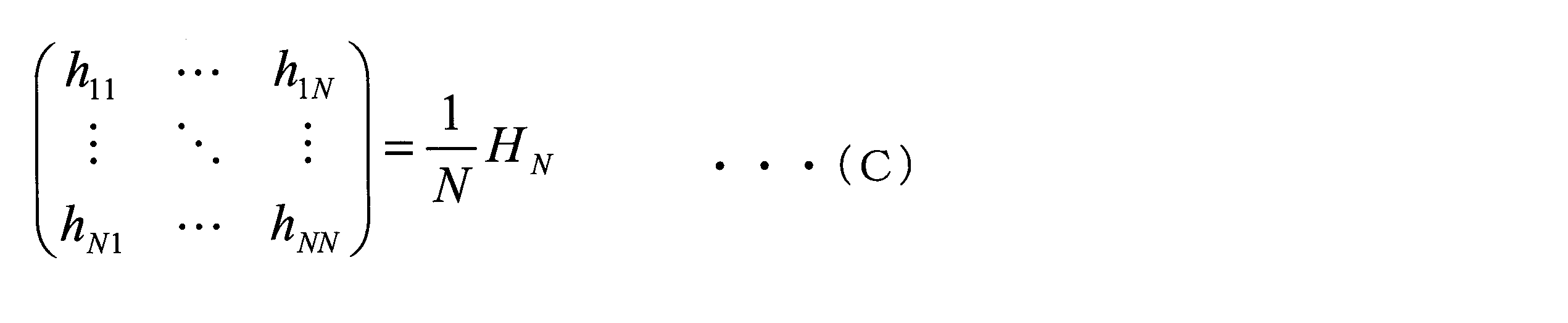
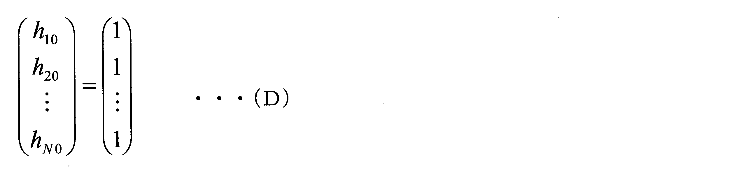
- 前記復号化部は、
前記N個のチャンネルにそれぞれ対応し、N個の適応デジタルフィルタを有するN個のフィルタ部と、
前記N個のチャンネルにそれぞれ対応するN個の判定機能部と、
を備え、
前記N個のチャンネルのうちi番目(iは1以上N以下の整数)のチャンネルの前記強度信号をBiで表し、
前記N個のフィルタ部のうち前記i番目のチャンネルに対応したフィルタ部が有する前記N個の適応デジタルフィルタのうちj番目(jは1以上N以下の整数)の適応デジタルフィルタのタップ係数をhijで表し、
前記i番目のチャンネルに対応した前記フィルタ部による処理後のデジタルデータをCiで表し、
N行N列のアダマール行列をHNで表したときに、
前記i番目のチャンネルに対応した前記フィルタ部は、式(E)によりデジタルデータCiを算出し、

前記タップ係数hijの初期値は、式(F)で定められる、

- 前記N個の適応デジタルフィルタのタップ長は、前記N個のチャンネルの波長分散値のうち最大の波長分散値に基づいて決定される、
請求項6又は請求項7に記載の復号化装置。 - 受信した波長多重信号を波長に基づきN個のチャンネルの光信号に分波する波長分波部と、
前記N個のチャンネルにそれぞれ対応し、前記波長分波部により分波された前記N個のチャンネルの前記光信号のうち対応するチャンネルの前記光信号を(NM+1)値(Mは1以上の整数)の電気信号である強度信号に変換するN個の受光部と、
前記N個のチャンネルにそれぞれ対応し、対応するチャンネルの前記強度信号をアナログ信号からデジタル信号に変換するN個のアナログデジタル変換部と、
前記N個の前記アナログデジタル変換部によりデジタル信号に変換された前記N個のチャンネルの前記強度信号における2L(Lは1以上の整数、2LはN以下)個の前記強度信号の組ごとに、2L行2L列のアダマール行列と、前記2L個の強度信号の組に含まれる2L個の前記強度信号を要素とする行列との内積を2Lで除算して得られた復号化信号のうち、取り得る値の範囲の最小値が正の前記復号化信号には(-M(2L-1)/2)を加算し、取り得る値の範囲の最小値が負の前記復号化信号には(M/2)を加算する復号化処理を行う復号化部と、
を備える復号化装置。
Priority Applications (4)
| Application Number | Priority Date | Filing Date | Title |
|---|---|---|---|
| JP2018546322A JP6560458B2 (ja) | 2016-10-18 | 2017-10-16 | 符号化装置及び復号化装置 |
| US16/340,658 US10693562B2 (en) | 2016-10-18 | 2017-10-16 | Encoding device and decoding device |
| CN201780060107.7A CN109792297B (zh) | 2016-10-18 | 2017-10-16 | 编码装置和解码装置 |
| US16/842,117 US10756819B2 (en) | 2016-10-18 | 2020-04-07 | Encoding device and decoding device |
Applications Claiming Priority (2)
| Application Number | Priority Date | Filing Date | Title |
|---|---|---|---|
| JP2016-204411 | 2016-10-18 | ||
| JP2016204411 | 2016-10-18 |
Related Child Applications (2)
| Application Number | Title | Priority Date | Filing Date |
|---|---|---|---|
| US16/340,658 A-371-Of-International US10693562B2 (en) | 2016-10-18 | 2017-10-16 | Encoding device and decoding device |
| US16/842,117 Division US10756819B2 (en) | 2016-10-18 | 2020-04-07 | Encoding device and decoding device |
Publications (1)
| Publication Number | Publication Date |
|---|---|
| WO2018074412A1 true WO2018074412A1 (ja) | 2018-04-26 |
Family
ID=62018689
Family Applications (1)
| Application Number | Title | Priority Date | Filing Date |
|---|---|---|---|
| PCT/JP2017/037353 Ceased WO2018074412A1 (ja) | 2016-10-18 | 2017-10-16 | 符号化装置及び復号化装置 |
Country Status (4)
| Country | Link |
|---|---|
| US (2) | US10693562B2 (ja) |
| JP (1) | JP6560458B2 (ja) |
| CN (1) | CN109792297B (ja) |
| WO (1) | WO2018074412A1 (ja) |
Cited By (1)
| Publication number | Priority date | Publication date | Assignee | Title |
|---|---|---|---|---|
| WO2020095986A1 (ja) * | 2018-11-08 | 2020-05-14 | 日本電信電話株式会社 | 光伝送システム |
Families Citing this family (3)
| Publication number | Priority date | Publication date | Assignee | Title |
|---|---|---|---|---|
| JP7121287B2 (ja) * | 2019-01-30 | 2022-08-18 | 日本電信電話株式会社 | 光伝送システム、光受信装置、及び光伝送方法 |
| US12073868B2 (en) * | 2022-06-07 | 2024-08-27 | Micron Technology, Inc. | Timing adjustment for data input/output buffer circuits |
| CN113392965B (zh) | 2021-08-18 | 2021-11-19 | 苏州浪潮智能科技有限公司 | 一种哈达玛积的实现方法、设备及存储介质 |
Citations (3)
| Publication number | Priority date | Publication date | Assignee | Title |
|---|---|---|---|---|
| JP2011029698A (ja) * | 2009-07-21 | 2011-02-10 | Nippon Telegr & Teleph Corp <Ntt> | 符号変換器、光符号分割多重用光送信機、及び光符号分割多重伝送システム |
| JP2011101475A (ja) * | 2009-11-05 | 2011-05-19 | Minebea Co Ltd | デジタル制御式負荷駆動装置 |
| JP2014107734A (ja) * | 2012-11-28 | 2014-06-09 | Nippon Telegr & Teleph Corp <Ntt> | 光伝送システム、光送信器、光受信器、光送信方法、光受信方法 |
Family Cites Families (25)
| Publication number | Priority date | Publication date | Assignee | Title |
|---|---|---|---|---|
| US4055756A (en) | 1975-02-03 | 1977-10-25 | Societe Anonyme De Telecommunications | Image coder-decoder using a matrix transform with weighted contribution of several points of the image to the formation of one point of the transform |
| US6584144B2 (en) | 1997-02-24 | 2003-06-24 | At&T Wireless Services, Inc. | Vertical adaptive antenna array for a discrete multitone spread spectrum communications system |
| US6025944A (en) * | 1997-03-27 | 2000-02-15 | Mendez R&D Associates | Wavelength division multiplexing/code division multiple access hybrid |
| US5955992A (en) | 1998-02-12 | 1999-09-21 | Shattil; Steve J. | Frequency-shifted feedback cavity used as a phased array antenna controller and carrier interference multiple access spread-spectrum transmitter |
| US7050723B2 (en) * | 2001-01-19 | 2006-05-23 | Nippon Telegraph And Telephone Corporation | Laser oscillator, optical communication method and system |
| US6424444B1 (en) * | 2001-01-29 | 2002-07-23 | Stratalight Communications, Inc. | Transmission and reception of duobinary multilevel pulse-amplitude-modulated optical signals using finite-state machine-based encoder |
| EP1335518B1 (en) | 2002-01-31 | 2005-11-09 | Motorola, Inc. | Reception of multicarrier spread-spectrum signals |
| US7599835B2 (en) | 2002-03-08 | 2009-10-06 | Nippon Telegraph And Telephone Corporation | Digital signal encoding method, decoding method, encoding device, decoding device, digital signal encoding program, and decoding program |
| EP1646165B1 (en) * | 2003-07-16 | 2010-09-15 | Nippon Telegraph And Telephone Corporation | Optical communication system using optical frequency code, optical transmission device and optical reception device thereof, and reflection type optical communication device |
| CA2524819C (en) * | 2004-12-13 | 2011-01-25 | Telcordia Technologies, Inc. | Spectrally phase encoded optical code division multiple access system |
| US8488967B2 (en) * | 2005-02-18 | 2013-07-16 | Telcordia Technologies, Inc. | System and method for OCDMA-based photonic layer security robustness to archival attack |
| US7646980B1 (en) * | 2006-05-08 | 2010-01-12 | Telcordia Technologies, Inc. | Variable spectral phase encoder/decoder based on decomposition of Hadamard codes |
| JP4977899B2 (ja) * | 2008-07-03 | 2012-07-18 | 国立大学法人山梨大学 | 光通信システム,光送信機,光受信機および方法ならびにこれらで用いる光相関器 |
| US8290371B2 (en) * | 2008-09-19 | 2012-10-16 | Telcordia Technologies, Inc. | OCDM-based all optical multi-level security |
| FR2965992B1 (fr) * | 2010-10-08 | 2014-04-04 | Inst Telecom Telecom Paristech | Methode et systeme de transmission wdm a codage chromato-temporel |
| US9100085B2 (en) * | 2011-09-21 | 2015-08-04 | Spatial Digital Systems, Inc. | High speed multi-mode fiber transmissions via orthogonal wavefronts |
| US9225453B2 (en) * | 2013-04-09 | 2015-12-29 | Futurewei Technologies, Inc. | Optimizing optical systems using code division multiple access and/or orthogonal frequency-division multiplexing |
| US9584259B2 (en) * | 2013-06-19 | 2017-02-28 | Mitsubishi Electric Research Laboratories, Inc. | Quaternary block-coded high-dimensional modulation for coherent optical communications |
| US9112653B2 (en) * | 2013-06-19 | 2015-08-18 | Mitsubishi Electric Research Laboratories, Inc. | Method and system for modulating optical signals as high-dimensional lattice constellation points to increase tolerance to noise |
| US8989300B1 (en) * | 2013-09-06 | 2015-03-24 | Avago Technologies General Ip (Singapore) Pte. Ltd. | Multi-level coding and distortion compensation |
| JP6631507B2 (ja) * | 2014-03-19 | 2020-01-15 | 日本電気株式会社 | 光送信器、光通信装置、光通信システムおよび光送信方法 |
| US9998187B2 (en) * | 2014-10-13 | 2018-06-12 | Nxgen Partners Ip, Llc | System and method for combining MIMO and mode-division multiplexing |
| US9680599B2 (en) * | 2014-10-27 | 2017-06-13 | Alcatel-Lucent Usa Inc. | Multichannel data transport suitable for direct optical detection at the receiver |
| WO2017184423A1 (en) * | 2016-04-21 | 2017-10-26 | Bribbla Dynamics Llc | Multiplexing and encoding for reference switching |
| US10594520B2 (en) | 2016-12-28 | 2020-03-17 | Sckipio Technologies S.I Ltd | System and method unifying linear and nonlinear precoding for transceiving data |
-
2017
- 2017-10-16 US US16/340,658 patent/US10693562B2/en active Active
- 2017-10-16 CN CN201780060107.7A patent/CN109792297B/zh active Active
- 2017-10-16 JP JP2018546322A patent/JP6560458B2/ja active Active
- 2017-10-16 WO PCT/JP2017/037353 patent/WO2018074412A1/ja not_active Ceased
-
2020
- 2020-04-07 US US16/842,117 patent/US10756819B2/en active Active
Patent Citations (3)
| Publication number | Priority date | Publication date | Assignee | Title |
|---|---|---|---|---|
| JP2011029698A (ja) * | 2009-07-21 | 2011-02-10 | Nippon Telegr & Teleph Corp <Ntt> | 符号変換器、光符号分割多重用光送信機、及び光符号分割多重伝送システム |
| JP2011101475A (ja) * | 2009-11-05 | 2011-05-19 | Minebea Co Ltd | デジタル制御式負荷駆動装置 |
| JP2014107734A (ja) * | 2012-11-28 | 2014-06-09 | Nippon Telegr & Teleph Corp <Ntt> | 光伝送システム、光送信器、光受信器、光送信方法、光受信方法 |
Cited By (3)
| Publication number | Priority date | Publication date | Assignee | Title |
|---|---|---|---|---|
| WO2020095986A1 (ja) * | 2018-11-08 | 2020-05-14 | 日本電信電話株式会社 | 光伝送システム |
| JP2020078001A (ja) * | 2018-11-08 | 2020-05-21 | 日本電信電話株式会社 | 光伝送システム |
| JP7193715B2 (ja) | 2018-11-08 | 2022-12-21 | 日本電信電話株式会社 | 光伝送システム |
Also Published As
| Publication number | Publication date |
|---|---|
| CN109792297A (zh) | 2019-05-21 |
| JPWO2018074412A1 (ja) | 2019-02-28 |
| US20200244369A1 (en) | 2020-07-30 |
| JP6560458B2 (ja) | 2019-08-14 |
| US20200052792A1 (en) | 2020-02-13 |
| US10756819B2 (en) | 2020-08-25 |
| CN109792297B (zh) | 2022-04-19 |
| US10693562B2 (en) | 2020-06-23 |
Similar Documents
| Publication | Publication Date | Title |
|---|---|---|
| JP6560458B2 (ja) | 符号化装置及び復号化装置 | |
| JP7700462B2 (ja) | 確率的整形及びシンボルレート最適化による光ネットワーク内の誤り訂正 | |
| JP6324620B2 (ja) | 光スーパーチャネルを介してデータを送信するための方法及びシステム | |
| WO2019004040A1 (ja) | 光送信機、光受信機及び光伝送システム | |
| JP6435059B2 (ja) | 光伝送システム及び光送信装置 | |
| EP3447938B1 (en) | Optical transmission method and optical transmission system | |
| JP6030027B2 (ja) | 光伝送システム | |
| JP5524900B2 (ja) | 光ファイバ伝送システム及び光受信装置 | |
| Ghazi et al. | Comparison of MD & ZCC one dimension code for optical-CDMA over multi-mode fiber based on Laguerre-Gaussian modes | |
| CN111988090B (zh) | 码片模式载波复合关联光编码方法 | |
| JP6456564B2 (ja) | 尤度生成装置、受信装置、尤度生成方法および光伝送システム | |
| JP7804235B2 (ja) | 信号処理装置、信号処理方法及びプログラム | |
| JP7193715B2 (ja) | 光伝送システム | |
| US11153012B1 (en) | Systems and methods in an optical network | |
| Nakashima et al. | Launch power optimization co-operated with digital nonlinear compensator for elastic optical network | |
| Lu et al. | Comparison and analysis of codes for remodulation WDM-PON with adaptive code selection | |
| Arnould | Ultra-wideband and high symbol rate transmission systems for next-generation optical fiber communications | |
| JP7723302B2 (ja) | 光伝送システム、送信装置、および制御方法 | |
| Wijanto et al. | Optimized Zero Cross-Correlation Code for Free Space and Underwater Optical Communication Using a Modular Rotational Matrix | |
| Kudojars et al. | Performance analysis of NRZ and Duobinary modulated WDM-PON transmission systems utilizing FEC codes | |
| Yan et al. | A Timing-synchronization-free WDM-compatible Colorless DRoF Uplink System for 5G Mobile Fronthaul Employing Gold Sequence Multiplexing | |
| Akyuz et al. | Adaptive entanglement distribution in wavelength-multiplexed, high-dimensional time-bin multi-user quantum networks | |
| Rashidi et al. | Enhanced the correlation effects for OCDMA systems based on algorithm of novel flexible cross correlation (FCC) code | |
| Rademacher et al. | Record Spectral Efficient Transmission of 11.24 Bit/s/Hz/mode over 30 km Few-Mode Fiber | |
| Udalcovs et al. | Proposed model of mixed-WDM systems resulting from development trends in optical transport and access networks |
Legal Events
| Date | Code | Title | Description |
|---|---|---|---|
| ENP | Entry into the national phase |
Ref document number: 2018546322 Country of ref document: JP Kind code of ref document: A |
|
| 121 | Ep: the epo has been informed by wipo that ep was designated in this application |
Ref document number: 17861228 Country of ref document: EP Kind code of ref document: A1 |
|
| NENP | Non-entry into the national phase |
Ref country code: DE |
|
| 122 | Ep: pct application non-entry in european phase |
Ref document number: 17861228 Country of ref document: EP Kind code of ref document: A1 |