WO2018073924A1 - スプライシング装置 - Google Patents
スプライシング装置 Download PDFInfo
- Publication number
- WO2018073924A1 WO2018073924A1 PCT/JP2016/081032 JP2016081032W WO2018073924A1 WO 2018073924 A1 WO2018073924 A1 WO 2018073924A1 JP 2016081032 W JP2016081032 W JP 2016081032W WO 2018073924 A1 WO2018073924 A1 WO 2018073924A1
- Authority
- WO
- WIPO (PCT)
- Prior art keywords
- feed hole
- carrier tape
- sprocket
- tape
- rotation angle
- Prior art date
- Legal status (The legal status is an assumption and is not a legal conclusion. Google has not performed a legal analysis and makes no representation as to the accuracy of the status listed.)
- Ceased
Links
Images





Classifications
-
- H—ELECTRICITY
- H05—ELECTRIC TECHNIQUES NOT OTHERWISE PROVIDED FOR
- H05K—PRINTED CIRCUITS; CASINGS OR CONSTRUCTIONAL DETAILS OF ELECTRIC APPARATUS; MANUFACTURE OF ASSEMBLAGES OF ELECTRICAL COMPONENTS
- H05K13/00—Apparatus or processes specially adapted for manufacturing or adjusting assemblages of electric components
- H05K13/02—Feeding of components
Definitions
- the splicing device 21 includes an insertion port 31 (only the insertion port 31 on the near side is shown in FIG. 1) communicating with the inside and the outside of the splicing device 21 on each of the side surfaces opposed in the longitudinal direction.
- the insertion port 31 is provided at a boundary portion between the main body portion 21a and the upper cover 21b, and is formed by cutting out part of the main body portion 21a and the upper cover 21b.
- the first carrier tape Tc ⁇ b> 1 (see FIG. 4) of the supply reel 25 is inserted into one of the two insertion ports 31 and the second insertion port 31 is out of components.
- the carrier tape Tc2 (see FIG. 4) is inserted.
- the second carrier tape Tc2 that is out of parts is inserted from the insertion port 31 on the near side in FIG.
- the first and second carrier tapes Tc1 and Tc2 are inserted into the insertion port 31, they are inserted into a tape transport path 32 provided in the splicing device 21.
- the tape conveyance path 32 is provided in the upper part of the main body 21a.
- the reel bucket 22 is provided on one side (the back side in FIG. 1) of the side surface facing in the longitudinal direction of the splicing device 21 and at a position close to the side surface.
- the reel bucket 22 is provided with an accommodating portion 22a that individually accommodates each of the plurality of supply reels 25.
- the main body control unit 12 can communicate with a host computer (not shown) by a wireless LAN through an access point provided in a communication network of a production factory, for example. For example, the main body control unit 12 transmits information such as the read barcode 25a to the host computer. Based on the received information such as the bar code 25a, the host computer determines whether or not the part code of the electronic part for which the splicing operation is to be performed matches. When the main body control unit 12 receives information from the host computer that it is satisfactory, the main body control unit 12 displays that fact on the display device 24. After confirming the display on the display device 24, the worker performs the splicing work using the splicing device 21. In this manner, the splicing unit 10 can prevent spurious splicing of an erroneous carrier tape such as a different type of electronic component by processing associated with the host computer.
- the display device 24 includes a touch panel 24a having a display function and an input function.
- the display device 24 displays the position information of the splicing target tape feeder, the component information of the barcode 25a read by the barcode reader 23, and the like on the touch panel 24a.
- Each of the cavities Ct is arranged with a predetermined interval between the feed hole Hc in the width direction of the base tape Tb.
- Each cavity Ct is disposed at a position between the feed holes Hc in the longitudinal direction of the first carrier tape Tc1.
- Each cavity Ct is formed as a receiving portion recessed in the base tape Tb, and has a bottomed box shape having an opening on the upper surface side.
- Each cavity Ct accommodates an electronic component e to be mounted on the substrate.
- the top tape Tt is detachably bonded to the upper surface side of the base tape Tb, that is, the opening side of the cavity Ct.
- the top tape Tt covers the opening of the cavity Ct.
- FIG. 5 shows the configuration of the splicing device 21.
- FIG. 6 is a block diagram of the splicing device 21 and shows a configuration related to the tape feeding device 37 (see FIG. 5).
- the first carrier tape Tc1 is inserted from the insertion port 31 on the left side (back side in FIG. 1) in FIG. 5
- the second carrier tape Tc2 is inserted from the insertion port 31 on the right side (front side in FIG. 1). Is inserted.
- Each of the first and second carrier tapes Tc1 and Tc2 is conveyed in the conveyance direction 35 on the tape conveyance path 32.
- the configuration on the first carrier tape Tc1 side left side in FIG.
- the control unit 36 detects that the leading end of the first carrier tape Tc1 has been inserted up to the inspection position L1 of the tape transport path 32 based on the detection information D1 of the tape detection unit 41. For example, the controller 36 determines that the first carrier tape Tc1 is not inserted up to the inspection position L1 in a state where the inspection light can be received by the tape detector 41. Moreover, the control part 36 determines with the 1st carrier tape Tc1 having been inserted to the test
- the sprocket 43 is disposed below the tape transport path 32 and is supported so as to be rotatable with respect to the main body 21a.
- the sprocket 43 has a substantially disk shape.
- a plurality of teeth 43 a are formed on the outer periphery of the sprocket 43 over the entire circumference.
- the teeth 43a are formed along the outer periphery of the sprocket 43 at the same interval as the interval Pc of the feed holes Hc.
- the tooth 43a located at the top is inserted into the through hole formed in the tape transport path 32 from below to above and is disposed at the engagement position Le.
- the tooth 43a located at the uppermost portion engages by inserting a portion protruding from the through hole of the tape transport path 32 into the feed hole Hc of the first carrier tape Tc1.
- the control unit 36 determines the light receiving state of the rotation angle detection unit 45 based on the rotation angle information D2 while driving the drive unit 44 and rotating the sprocket 43 in a startup process (step 11 in FIG. 7) described later. .
- the control unit 36 stops the rotation of the sprocket 43 and positions it at the origin position.
- the control unit 36 detects the rotation angle of the sprocket 43 based on the angle obtained by rotating the sprocket 43 from the origin position with reference to the origin position.
- the rotation angle detection unit 45 is not limited to the configuration described above, and may be configured to detect the origin position by reading a mark attached to the side surface of the sprocket 43, for example.
- the urging portion 47 is provided above the tape transport path 32 at the engagement position Le.
- the urging portion 47 urges the first carrier tape Tc1 toward the sprocket 43 and engages the teeth 43a with the feed hole Hc.
- the urging portion 47 includes a spring 47a and a pressing member 47b. One end of the spring 47a is fixed to the upper cover 21b, and a pressing member 47b is attached to the other end.
- the urging portion 47 urges the pressing member 47b downward by the elastic force of the spring 47a.
- the urging portion 47 urges the first carrier tape Tc1 inserted between the pressing member 47b and the tooth 43a at the uppermost portion (engagement position Le) by the pressing member 47b.
- the urging portion 47 is not limited to the spring 47a, and may be configured to urge the first carrier tape Tc1 with rubber or the like.
- the feed hole detection unit 48 projects inspection light from the light projecting unit provided above the tape transport path 32 toward the inspection position L2 on the tape transport path 32 below, and sends the light according to the light receiving state of the light receiving unit.
- the hole position information D3 is output to the control unit 36 (see FIG. 6).
- the feed hole detector 48 is in a light receiving state until the first carrier tape Tc1 is conveyed to the inspection position L2. Further, the feed hole detecting unit 48 is in a light receiving state when the feed hole Hc is disposed at the inspection position L2. Further, the feed hole detecting unit 48 is in a non-light receiving state when a portion other than the feed hole Hc of the first carrier tape Tc1 (base tape Tb) is disposed at the inspection position L2. Accordingly, the feed hole detection unit 48 switches between the light receiving state and the non-light receiving state as the first carrier tape Tc1 is conveyed.
- the control unit 36 feeds the feed hole to the inspection position L2. It is determined that Hc is arranged.
- the cutting device 38 is a device that cuts the first carrier tape Tc1 at the center position of the feed hole Hc, and is attached in the upper cover 21b, for example.
- the cutting device 38 includes a cutter 51, a cam 52, a motor 53, a spring 54, a pressing member 55, and a spring 56.
- the cutter 51 is provided above the tape conveyance path 32 at the tape cutting position Lc, and is provided so as to be movable in the vertical direction.
- the cutter 51 descends and cuts the first carrier tape Tc1 positioned at the tape cutting position Lc.
- the cam 52 is provided in contact with the cutter 51.
- the motor 53 has an output shaft and a cam 52 connected to each other.
- the cam 52 rotates while slidingly contacting the cutter 51 in accordance with the drive of the motor 53, and moves the cutter 51 in the vertical direction.
- the spring 54 has an upper end fixed to the upper cover 21b and a cutter 51 attached to the lower end. The spring 54 extends in accordance with the downward movement of the cutter 51 and applies an upward biasing force to the cutter 51.
- the pressing member 55 is provided adjacent to the cutter 51 and is provided so as to be movable in the vertical direction.
- the spring 56 has an upper end attached to the cutter 51, and a pressing member 55 attached to the lower end.
- the spring 56 contracts in accordance with the downward movement of the cutter 51 and applies a downward biasing force to the pressing member 55.
- the pressing member 55 presses the vicinity of the cut portion of the first carrier tape Tc1 positioned at the tape cutting position Lc from the upper surface, and sandwiches and fixes the first carrier tape Tc1 between the tape conveying path 32 and the pressing member 55.
- the movable member 61 includes a movable conveyance path 61a constituting a part of the tape conveyance path 32, an opening 61b for taking in an unnecessary part of the first carrier tape Tc1, and a duct 61c for guiding the taken-in unnecessary part to a disposal part. And.
- the movable member 61 is held at an angle (an angle indicated by a broken line in FIG. 5) at which the opening 61b is positioned on the tape transport path 32 in a normal state.
- the movable member 61 is rotated by the driving device 63 after taking an unnecessary portion into the opening 61b in accordance with the cutting of the first carrier tape Tc1.
- the driving device 63 rotates the movable conveyance path 61a of the movable member 61 to an angle parallel to the tape conveyance path 32 (an angle indicated by a solid line in FIG. 5).
- the first carrier tape Tc1 is cut at the tape cutting position Lc and an unnecessary portion is collected, and then conveyed and positioned by the sprocket 43 from the tape cutting position Lc to the splicing position Lp.
- the splicing device 21 is in a state where the cut surfaces of the first and second carrier tapes Tc1 and Tc2 are abutted with each other at the splicing position Lp (see FIG. 4), and the splicing portion is connected to the first and second carrier tapes Tc1 and Tc2. Joining with a tape (not shown).
- the splicing device 21 opens the upper cover 21b so that the spliced carrier tape (the spliced first and second carrier tapes Tc1 and Tc2) can be taken out.
- FIG. 7 is a flowchart showing the processing contents of the splicing device 21.
- the splicing unit 10 receives information on a tape feeder (second carrier tape Tc2) that is out of parts from a host computer (not shown)
- the splicing unit 10 displays the information on the display device 24.
- the operator confirms the display content of the display device 24, moves to the tape feeder where the parts are run out, and performs the work of splicing the first carrier tape Tc1 to the second carrier tape Tc2.
- the splicing process for the second carrier tape Tc2 in the splicing device 21 is the same as the process for the first carrier tape Tc1.
- the process with respect to 1st carrier tape Tc1 is mainly demonstrated, and the description of the process with respect to 2nd carrier tape Tc2 is abbreviate
- the worker executes splicing verification using the barcode reader 23.
- the operator confirms that the splicing verification is good by viewing the display on the display device 24, the operator inserts each of the first and second carrier tapes Tc1 and Tc2 into the two insertion openings 31, respectively.
- the first carrier tape Tc ⁇ b> 1 is inserted from the insertion port 31 toward the engagement position Le along the transport direction 35 with the lower surface supported by the tape transport path 32.
- the control unit 36 detects that the first carrier tape Tc1 has been inserted from the insertion port 31 based on the detection information D1 of the tape detection unit 41 (S12).
- the control unit 36 drives the drive unit 44 to rotate the sprocket 43 (clockwise in FIG. 9), and conveys the first carrier tape Tc1 toward the inspection position L2 of the feed hole detection unit 48 (S13). ).
- the tip of the first carrier tape Tc1 is conveyed to the inspection position L2.
- the most distal feed hole Hc is the inspection position L2.
- the control unit 36 Based on the feed hole position information D3 of the feed hole detection unit 48, the control unit 36 detects that the feed hole Hc is arranged at the inspection position L2 (S14).
- the control unit 36 calculates the rotation angle of the sprocket 43 (S15). For example, the control unit 36 detects the angle at which the motor of the drive unit 44 is rotated based on information of the encoder of the drive unit 44. The control unit 36 calculates the rotation angle of the sprocket 43 based on the angle obtained by rotating the sprocket 43 from the origin position using the origin position shown in FIGS. 8 and 9 as a reference.
- the sprocket 43 of the present embodiment is fed by the feed hole detector 48 shown in FIG. 10 from the state where the feed hole Hc is engaged with the teeth 43a of the engagement position Le at the origin position shown in FIG.
- the inspection position L2 of the feed hole detection unit 48 detects the feed hole Hc when the sprocket 43 is rotated from the origin position by the normal rotation angle ⁇ 1 while the feed hole Hc is correctly engaged with the teeth 43a (for example, , The position to be detected first).
- the distance 71 between the engagement position Le and the inspection position L2 is a distance that is an integral multiple of the interval Pc between the feed holes Hc.
- the control unit 36 determines the rotation angle of the sprocket 43 at the timing when the feed hole detection unit 48 detects the feed hole Hc, so that the first carrier tape Tc1 is engaged with the teeth 43a in the feed hole Hc. It is possible to determine whether or not the vehicle is being transported by the sprocket 43 (hereinafter referred to as “normal transport state”) (S16).
- the control unit 36 determines whether or not the rotation angle calculated in S15 is the normal rotation angle ⁇ 1.
- the rotation angle is the normal rotation angle ⁇ 1, that is, in the normal conveyance state (S16: YES)
- the control unit 36 continues the normal splicing operation. Note that, even if the rotation angle does not completely coincide with the normal rotation angle ⁇ 1, the control unit 36 is in the normal conveyance state, for example, when the rotation angle is within a predetermined range with the normal rotation angle ⁇ 1 as a reference. You may judge.
- the control unit 36 drives the drive unit 44 to further rotate the sprocket 43, and conveys the first carrier tape Tc1 toward the tape cutting position Lc (S17).
- the control unit 36 controls the cutting device 38 to cut unnecessary portions of the first carrier tape Tc1 (S17).
- the control unit 36 cuts unnecessary portions of the second carrier tape Tc2 by the cutting device 38 (S17).
- the control unit 36 performs splicing by matching the cut surfaces of the first and second carrier tapes Tc1 and Tc2 (S18).
- the control unit 36 opens the upper cover 21b and allows the first and second carrier tapes Tc1 and Tc2 that have been spliced to be taken out (S18).
- the splicing device 21 can normally complete the splicing operation without cutting the first and second carrier tapes Tc1 and Tc2 at a position shifted from the center of the feed hole Hc.
- abnormal transport state a state that is not in a normal transport state
- the first carrier tape Tc1 is inserted between the teeth 43a of the sprocket 43 at the origin position and the pressing member 47b of the urging portion 47 when inserted to the engagement position Le by the operator.
- a portion other than the feed hole Hc a tip portion in the illustrated example
- the first carrier tape Tc1 is more likely to be sandwiched between the teeth 43a and the pressing member 47b.
- the first carrier tape Tc1 When the sprocket 43 rotates from the origin position in this sandwiched state, as shown in FIG. 12, the first carrier tape Tc1 is sandwiched between the pressing member 47b and the teeth 43a, and the teeth 43a other than the feed hole Hc. It becomes an abnormal conveyance state where the part is pushed and conveyed. In the abnormal transport state in which the teeth 43a and the feed hole Hc are transported without being engaged, the first carrier tape Tc1 (particularly the front end portion) is transported to a position shifted from the position in the normal transport state. As a result, the splicing device 21 may cut the first carrier tape Tc1 at a position shifted from the center of the feed hole Hc and execute splicing.
- the rotation angle of the sprocket 43 at the timing when the feed hole detection unit 48 detects the feed hole Hc becomes an abnormal rotation angle ⁇ 2 different from the normal rotation angle ⁇ 1 in the normal conveyance state shown in FIG. (See FIG. 12).
- the sprocket 43 is further on the tip side than the feed hole Hc on the most tip side.
- the rotation starts from a state (origin position) where the teeth 43a are in contact with the position.
- the abnormal rotation angle ⁇ 2 at the timing when the feed hole detection unit 48 detects the feed hole Hc is larger than the normal rotation angle ⁇ 1 (see FIG. 10).
- the tip of the first carrier tape Tc1 until the feed hole Hc on the most tip side is downstream (tape cutting position Lc side) from the engagement position Le. Is considered to be inserted into the tape transport path 32 by the operator.
- the sprocket 43 at the origin position is in a state where the portion on the upstream side (insertion port 31 side) of the feed hole Hc is sandwiched between the teeth 43a and the pressing member 47b.
- the abnormal rotation angle ⁇ 2 is smaller than the normal rotation angle ⁇ 1 (see FIG. 10), contrary to the case described above.
- the control unit 36 determines whether or not to continue the splicing work (S21). Even in the abnormal conveyance state shown in FIG. 11 and FIG. 12, the worker may want to continue the splicing work and complete the splicing. Therefore, for example, the control unit 36 displays a selection screen as to whether or not to continue the splicing work on the display device 24 (S21). At this time, the control unit 36 may display information useful for the operator's judgment on the display device 24 in addition to the selection screen, such as the magnitude of the deviation of the abnormal rotation angle ⁇ 2.
- control unit 36 executes the processes of S17 and S18 to complete the splicing work. Thereby, even if it is an abnormal conveyance state, the presence or absence of splicing operation
- work can be selected by an operator's judgment.
- the control unit 36 stops the splicing work, opens the upper cover 21b, and is in a state where the first and second carrier tapes Tc1, Tc2 can be taken out. To do. Thereby, the worker can perform appropriate measures such as performing the splicing work again using the first and second carrier tapes Tc1, Tc2.
- the splicing device 21 of the above-described embodiment is a splicing device that splices the first carrier tape Tc1 (carrier tape) in which the feed holes Hc and the component storage cavities Ct are provided at regular intervals.
- the splicing device 21 communicates the upper cover 21b and the main body portion 21a (housing) with the inside and outside of the upper cover 21b and the main body portion 21a, the insertion port 31 into which the first carrier tape Tc1 can be inserted, the upper cover 21b and the main body.
- a tape transport path 32 that is provided in the portion 21a and supports the first carrier tape Tc1 inserted from the insertion port 31, and a first supported by the tape transport path 32 so as to be rotatable with respect to the main body portion 21a.
- a sprocket 43 having teeth 43a that engage with the feed holes Hc of the carrier tape Tc1, a drive unit 44 that rotates the sprocket 43 and conveys the first carrier tape Tc1 along the tape conveyance path 32, and a rotation angle of the sprocket 43
- the rotation angle detection unit 45 for detecting the rotation angle information D2 related to the first carrier tape Tc1 and the conveyance of the first carrier tape Tc1
- a feed hole detector 48 for detecting the feed hole position information D3 according to the position of the feed bores Hc exposed
- a control unit 36 for inputting the rotation angle information D2 and the feed hole position information D3, the.
- the control part 36 determines whether it is a normal conveyance state based on the relationship between the rotation angle of the sprocket 43 and the position of the feed hole Hc. Thereby, the control part 36 can detect the abnormal conveyance state which is conveying the 1st carrier tape Tc1 although the tooth
- the feed hole detecting section 48 is provided at a position for detecting the feed hole Hc of the transported first carrier tape Tc1 when the sprocket 43 is rotated from the origin position to the normal rotation angle ⁇ 1 in the normal transport state. .
- the control unit 36 determines that it is in the normal conveyance state.
- the feed hole detecting section 48 is provided at a position where the feed hole Hc is detected when the sprocket 43 is rotated from the origin position to the normal rotation angle ⁇ 1. For this reason, the control part 36 can determine whether it is a normal conveyance state by comparing the rotation angle of the timing which detected the feed hole Hc with the feed hole detection part 48 with normal rotation angle (theta) 1. Thereby, the control part 36 can determine whether it is a normal conveyance state by an easy process.
- the feed hole detecting unit 48 detects the feed hole Hc at a position downstream of the engagement position Le where the teeth 43a and the feed hole Hc are engaged in the transport direction 35 of the first carrier tape Tc1.
- the feed holes Hc are in a normal transport state (see FIG. 11). 9 and FIG. 10).
- the shift of the feed hole Hc may occur more significantly on the downstream side than on the upstream side of the engagement position Le.
- the feed hole detection unit 48 detects the feed hole Hc downstream from the engagement position Le, thereby accurately determining whether the feed hole Hc is misaligned, that is, in a normal transport state. It becomes possible to detect.
- the splicing device 21 further includes a biasing portion 47 that biases the first carrier tape Tc1 toward the sprocket 43 and engages the teeth 43a with the feed hole Hc.
- the first carrier tape Tc1 inserted from the insertion port 31 is urged toward the sprocket 43 by the urging portion 47, so that the teeth 43a are easily engaged with the feed hole Hc.
- the first carrier tape Tc1 is sandwiched between the urging portion 47 and the teeth 43a of the sprocket 43, and conveyed without the teeth 43a being engaged with the feed holes Hc.
- control unit 36 when it is determined that the control unit 36 is not in the normal conveyance state, the control unit 36 notifies that (S19 in FIG. 7).
- the operator can recognize the occurrence of the abnormal conveyance state by the notification from the splicing device 21.
- the operator can take appropriate measures such as taking out the first carrier tape Tc1 and performing the splicing operation again.
- the control unit 36 determines the normal conveyance state based on the rotation angle from the origin position, but the determination method of the normal conveyance state is not limited to this.
- the teeth 43a of the sprocket 43 are provided on the outer periphery of the sprocket 43 with a spacing Pc. Each time the sprocket 43 rotates by a predetermined angle, a different tooth 43a is arranged at the engagement position Le. For example, consider a case where 30 teeth 43a are provided on the outer periphery of the sprocket 43 at intervals Pc.
- the control unit 36 determines the position of the feed hole Hc using the feed hole position information D3 of the feed hole detection unit 48.
- the present invention is not limited to this.
- the control unit 36 may determine the position of the feed hole Hc using the cavity position information D4 of the cavity detection unit 49.
- the spacing Pc between the feed holes Hc and the spacing Pc between the cavities Ct are determined by the standard of the first carrier tape Tc1 and have a certain relationship. For this reason, the control part 36 may determine the timing which detects the position of the feed hole Hc from the cavity position information D4, and determines a rotation angle.
- the operator may input auxiliary information (standard or the like) from the display device 24 for determining the relationship between the interval Pc between the feed holes Hc and the interval Pc between the cavities Ct.
- the control part 36 becomes possible [detecting the position of the feed hole Hc more accurately from the cavity position information D4 based on the information input from the display apparatus 24].
- the splicing device 21 since the splicing device 21 can use the cavity detection unit 49 as the feed hole detection unit in the present application, the splicing device 21 may be configured not to include the feed hole detection unit 48 of the above embodiment.
- control unit 36 is configured to determine the origin position based on the rotation angle information D2 of the rotation angle detection unit 45 and detect the rotation angle of the sprocket 43 based on the rotation angle from the origin position.
- the configuration for detecting the rotation angle of the sprocket 43 is not limited to this.
- the rotation angle detection unit 45 may be an encoder that outputs the rotation angle of the sprocket 43 as the rotation angle information D2.
- the control unit 36 can detect the rotation angle of the sprocket 43 only with the rotation angle information D2 of the rotation angle detection unit 45.
- the feed hole detection unit 48 is provided downstream of the engagement position Le, but may be provided upstream.
- the control unit 36 detects the first carrier tape Tc1 by the tape detection unit 41 and then detects a predetermined number of feed holes Hc by the feed hole detection unit 48 (a certain amount from the engagement position Le).
- the rotation angle may be determined (S16) at the timing when only the sheet is conveyed).
- the splicing device 21 may be configured not to include the urging unit 47.
- the splicing device 21 may include a guide groove that guides the first carrier tape Tc1 toward the sprocket 43 so that the feed hole Hc is engaged with the teeth 43a.
- control part 36 determined the normal conveyance state about both 1st and 2nd carrier tape Tc1, Tc2, either carrier tape, for example, 1st carrier tape Tc1 for replenishment, is determined. Only the normal conveyance state may be determined. In this case, the splicing device 21 does not need to include the feed hole detection unit 48 for the second carrier tape Tc2.
- the control unit 36 may be configured not to execute the determination (S21) as to whether or not to continue the splicing work. In this case, the control unit 36 may end the process of FIG. 7 after displaying an error on the display device 24 in S19.
- 21 Splicing device
- 21a main body (housing)
- 21b upper cover (housing)
- 31 insertion port
- 32 tape conveying path
- 35 conveying direction
- 36 control unit
- 43 sprocket
- 43a Teeth
- Drive unit 45 Rotation angle detection unit
- Ct Cavity
- D2 Rotation angle information
- D3 Feed hole position information
- Hc Feed hole Le : Engagement position
- Tc1 first carrier tape (carrier tape)
- Tc2 second carrier tape (carrier tape)
- ⁇ 1 normal rotation angle.
Landscapes
- Engineering & Computer Science (AREA)
- Manufacturing & Machinery (AREA)
- Microelectronics & Electronic Packaging (AREA)
- Supply And Installment Of Electrical Components (AREA)
Abstract
キャリアテープが所望の切断位置からずれた位置で切断される事態の発生を抑制できるスプライシング装置を提供すること。 スプライシング装置21の制御部36は、スプロケット43の回転角度と、送り穴Hcの位置と、の関係に基づいて、送り穴Hcに歯43aが係合した状態で第一キャリアテープTc1がスプロケット43により搬送されている正常搬送状態であるか否かを判定する。これにより、制御部36は、スプロケット43の歯43aが第一キャリアテープTc1の送り穴Hcに係合していないにも係わらず第一キャリアテープTc1を搬送している異常搬送状態を検出できる。
Description
本発明は、電子部品装着機のテープフィーダに装填されたリールのキャリアテープに補給用のキャリアテープをスプライシングして、電子部品の補給を行うスプライシング装置に関するものである。
電子部品装着機には、例えば、電子部品を供給するテープフィーダが装着されている。また、このテープフィーダには、リールが装填されている。リールには、複数の電子部品を一定の間隔で収納したキャリアテープが巻回されている。電子部品装着機は、テープフィーダを駆動してキャリアテープから電子部品を順次供給し基板に装着する。また、電子部品装着機の作業者は、各テープフィーダの電子部品がなくなって生産ラインが停止する前に、電子部品を補給する作業を行う。特許文献1には、部品切れになりそうなキャリアテープの終端と、補給用のキャリアテープの始端とのスプライシングを自動で行うスプライシング装置が記載されている。
スプライシング装置は、装置に挿入された2つのキャリアテープの送り穴にスプロケットの歯を係合させ、スプロケットを回転させることでキャリアテープを搬送する。スプライシング装置は、例えば、2つのキャリアテープの各々を円形の送り穴の中心を通る位置で切断し、先端の送り穴を半円形状にする。スプライシング装置は、切断した2つのキャリアテープを搬送し、先端の半円形状となった送り穴を互いに突き合わせて円形の送り穴を構成する。スプライシング装置は、この状態で2つのキャリアテープの先端をスプライシングテープによりスプライシングする。
ところで、上記したスプライシング装置では、キャリアテープの搬送時に、スプロケットの歯がキャリアテープの送り穴に係合していないにも係わらず、スプロケットの回転にともなってキャリアテープを歯で押して搬送してしまう虞がある。この場合、キャリアテープの先端は、送り穴にスプロケットの歯を係合させ正常に搬送した場合の位置から、ずれた位置に搬送される。その結果、キャリアテープは、送り穴の中心を通る所望の位置からずれた位置で切断される虞がある。
本発明は、上記した課題に鑑みてなされたもので、キャリアテープが所望の切断位置からずれた位置で切断される事態の発生を抑制できるスプライシング装置を提供することを目的とする。
本明細書に開示するスプライシング装置は、送り穴と部品収納用のキャビティとをそれぞれ一定の間隔に設けたキャリアテープをスプライシングするスプライシング装置であって、筐体と、筐体の内外を連通し、キャリアテープを挿入可能な挿入口と、筐体内に設けられ、挿入口から挿入されたキャリアテープを支持するテープ搬送路と、筐体に対して回転可能に支持され、テープ搬送路に支持されたキャリアテープの送り穴に係合する歯を有するスプロケットと、スプロケットを回転させ、キャリアテープをテープ搬送路に沿って搬送する駆動部と、スプロケットの回転角度に係わる回転角度情報を検出する回転角度検出部と、キャリアテープの搬送にともなって変更される送り穴の位置に係わる送り穴位置情報を検出する送り穴検出部と、回転角度情報及び送り穴位置情報を入力する制御部と、を備え、制御部は、回転角度情報に基づくスプロケットの回転角度と、送り穴位置情報に基づく送り穴の位置と、の関係に基づいて、送り穴に歯が係合した状態でキャリアテープがスプロケットにより搬送されている正常搬送状態であるか否かを判定する。
これによれば、制御部は、スプロケットの回転角度と送り穴の位置との関係に基づいて、正常搬送状態であるか否かを判定する。これにより、制御部は、スプロケットの歯がキャリアテープの送り穴に係合していないにも係わらずキャリアテープを搬送している異常搬送状態を検出できる。この場合、制御部は、例えば、スプライシング作業の中止や作業者への通知など、適切な処理を実施できる。その結果、キャリアテープが所望の位置からずれた位置で切断される事態の発生を抑制できる。
以下、本発明のスプライシング装置を具体化した一実施形態について図面を参照して説明する。なお、説明に用いる各図は概念図であり、各部の形状は必ずしも厳密なものではない場合がある。
(1.スプライシングユニット10の構成)
まず、図1に示すスプライシング装置21を備えるスプライシングユニット10について説明する。図1は、スプライシングユニット10の全体の斜視図を示している。スプライシングユニット10は、リールバケット22の補給用リール25の第一キャリアテープTc1(図4参照)と、図示しない電子部品装着機のテープフィーダに装填されたリールの第二キャリアテープTc2(図4参照)とをスプライシング装置21によりスプライシングする装置である。
(1.スプライシングユニット10の構成)
まず、図1に示すスプライシング装置21を備えるスプライシングユニット10について説明する。図1は、スプライシングユニット10の全体の斜視図を示している。スプライシングユニット10は、リールバケット22の補給用リール25の第一キャリアテープTc1(図4参照)と、図示しない電子部品装着機のテープフィーダに装填されたリールの第二キャリアテープTc2(図4参照)とをスプライシング装置21によりスプライシングする装置である。
図1に示すように、スプライシングユニット10は、台車部11と、本体制御部12と、を備えている。台車部11は、4つのキャスター13(図1においては3つのみ図示)の上にベース台14を取り付けて構成されている。ベース台14の上には、電源装置15と、ダストボックス17と、が配置されている。
電源装置15は、バッテリーを備えており、本体制御部12の電源スイッチ12aがオン操作されることで、スプライシング装置21や表示装置24に電力を供給する。ダストボックス17は、スプライシング作業にともなって発生するキャリアテープの切れ端(廃テープ)等を捨てるためのものである。
また、本体制御部12は、ベース台14の上に固定された柱部18の上部に取り付けられている。本体制御部12は、スプライシング装置21と、リールバケット22と、バーコードリーダ23と、表示装置24と、を備えている。
スプライシング装置21は、テープフィーダ(図示略)に装填されたリールに巻回された第二キャリアテープTc2(図4参照)の終端を、リールバケット22に収容された補給用リール25に巻回された第一キャリアテープTc1(図4参照)の始端に自動的にスプライシングする装置である。スプライシング装置21は、本体部21a(筐体)と、本体部21aに対して開閉可能に取り付けられた上部カバー21b(筐体)と、を備えている。スプライシング装置21は、上部カバー21bを閉じた状態では、全体の形状として一方向に長い略直方体形状をなしている。スプライシング装置21は、長手方向で対向する側面の各々に、スプライシング装置21の内外を連通する挿入口31(図1では手前側の挿入口31のみを図示)を備えている。挿入口31は、本体部21aと上部カバー21bとの境界部分に設けられ、本体部21a及び上部カバー21bの一部を切り欠いて形成されている。
スプライシング装置21は、2つの挿入口31のうち、一方の挿入口31に補給用リール25の第一キャリアテープTc1(図4参照)を挿入され、他方の挿入口31から部品切れとなる第二キャリアテープTc2(図4参照)を挿入される。例えば、本実施形態のスプライシング装置21では、部品切れとなる第二キャリアテープTc2を図1における手前側の挿入口31から挿入する。第一及び第二キャリアテープTc1,Tc2は、挿入口31に挿入されると、スプライシング装置21内に設けられたテープ搬送路32に挿入される。テープ搬送路32は、本体部21aの上部部分に設けられている。
また、スプライシング装置21は、スプライシング時には上部カバー21bを閉じた状態で保持する。また、スプライシング装置21は、スプライシングの完了にともなって上部カバー21bを開いた状態にしてスプライシングの完了したキャリアテープを取り出せる状態にする。なお、スプライシング装置21の詳細な構成については後述する。
リールバケット22は、スプライシング装置21の長手方向で対向する側面の一方側(図1における奥側)であって、その側面に近接した位置に設けられている。リールバケット22には、複数の補給用リール25の各々を、個別に収容する収容部22aが設けられている。
バーコードリーダ23は、例えば、本体制御部12と無線通信を行うコードレスのハンディタイプのものである。作業者は、バーコードリーダ23によってリールバケット22から取り出した補給用リール25のバーコード25aやテープフィーダから取り外したリールのバーコードを読み込む作業を行う。これにより、本体制御部12は、スプライシング作業において、正しい電子部品を収容した第一キャリアテープTc1(補給用リール25)を準備したかどうかをチェックする、いわゆるスプライシングベリファイを実行する。
本体制御部12は、例えば、生産工場の通信ネットワークに設けられたアクセスポイントを通じて無線LANによりホストコンピュータ(図示略)と通信可能となっている。本体制御部12は、例えば、読み込まれたバーコード25a等の情報をホストコンピュータに送信する。ホストコンピュータは、受信したバーコード25a等の情報に基づいて、スプライシング作業を実行しようとしている電子部品の部品コードが一致しているか等の良否を判定する。本体制御部12は、ホストコンピュータから良好である旨を受信すると、表示装置24にその旨を表示する。作業者は、表示装置24の表示を確認した後、スプライシング装置21を使用してスプライシング作業を行う。このように、スプライシングユニット10は、ホストコンピュータと連係した処理により、電子部品の種類が異なる等の誤ったキャリアテープがスプライシングされることを防止することが可能となっている。
表示装置24は、表示機能と入力機能とを有するタッチパネル24aを備えている。表示装置24は、スプライシング対象のテープフィーダの位置情報やバーコードリーダ23で読み込まれたバーコード25aの部品情報などをタッチパネル24aに表示する。
(2.キャリアテープの構成)
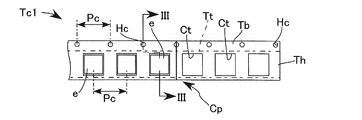
次に、キャリアテープの構成について説明する。図2は、第一キャリアテープTc1の平面図を示している。図3は、図2のIII-III線に沿って切断した断面図を示している。図4は、第一及び第二キャリアテープTc1,Tc2をスプライシングする状態を示している。図4に示す第一キャリアテープTc1は、例えば、補給用リール25に巻回されたキャリアテープである。第二キャリアテープTc2は、例えば、テープフィーダに装填されたリールの部品切れとなるキャリアテープである。第一及び第二キャリアテープTc1,Tc2は、同一構造をなしている。このため、以下の説明では、第一キャリアテープTc1を主に説明し、第二キャリアテープTc2についての説明を適宜省略する。
次に、キャリアテープの構成について説明する。図2は、第一キャリアテープTc1の平面図を示している。図3は、図2のIII-III線に沿って切断した断面図を示している。図4は、第一及び第二キャリアテープTc1,Tc2をスプライシングする状態を示している。図4に示す第一キャリアテープTc1は、例えば、補給用リール25に巻回されたキャリアテープである。第二キャリアテープTc2は、例えば、テープフィーダに装填されたリールの部品切れとなるキャリアテープである。第一及び第二キャリアテープTc1,Tc2は、同一構造をなしている。このため、以下の説明では、第一キャリアテープTc1を主に説明し、第二キャリアテープTc2についての説明を適宜省略する。
図2及び図3に示すように、第一キャリアテープTc1は、ベーステープTbと、電子部品eと、トップテープTtと、を備えている。ベーステープTbは、所定の幅で細長く形成されている。ベーステープTbには、長手方向に沿って送り穴Hc及び部品収納用のキャビティCtが同一の間隔Pcで配列されている。なお、送り穴HcとキャビティCtとは、異なる間隔Pcでもよい。各送り穴Hcは、ベーステープTbを貫通して形成され、ベーステープTbの平面視において円形をなしている。各送り穴Hcは、ベーステープTbの幅方向における側縁部に設けられ、長手方向に沿って間隔Pcで配列されている。
各キャビティCtは、ベーステープTbの幅方向において送り穴Hcと所定の間隔を間に設けて配置されている。各キャビティCtは、第一キャリアテープTc1の長手方向において各送り穴Hcの間となる位置に配置されている。各キャビティCtは、ベーステープTbに凹設された収容部として形成され、上面側に開口を有した有底箱形をなしている。各キャビティCtには、基板に装着される電子部品eがそれぞれ収容されている。トップテープTtは、ベーステープTbの上面側、即ち、キャビティCtの開口側に剥離可能に接着されている。トップテープTtは、キャビティCtの開口を被覆している。
また、図2に示すように、例えば、第一キャリアテープTc1の先端部Thから3つのキャビティCtには、電子部品eを収容していない空きのキャビティCtが設けられている。スプライシング装置21は、例えば、空きのキャビティCtをなくし、且つ円形の送り穴Hcの中心を通る切断位置Cpで第一キャリアテープTc1を切断する。図4に示すように、スプライシング装置21は、第一及び第二キャリアテープTc1,Tc2の各々を切断位置Cpで切断した後、互いに近接する方向(図4中の搬送方向35)に搬送する。スプライシング装置21は、切断位置Cpの半円形状となった送り穴Hcをスプライシング位置Lp(図5参照)で互いに突き合わせて円形となるように第一及び第二キャリアテープTc1,Tc2を近接させた状態で、スプライシングテープ(図示略)によりスプライシングを行う。
(3.スプライシング装置21の構成)
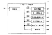
図5は、スプライシング装置21の構成を示している。図6は、スプライシング装置21のブロック図であり、テープ送り装置37(図5参照)に係わる構成を示している。スプライシング装置21は、例えば、図5における左側(図1における奥側)の挿入口31から第一キャリアテープTc1が挿入され、右側(図1における手前側)の挿入口31から第二キャリアテープTc2が挿入される。第一及び第二キャリアテープTc1,Tc2の各々は、テープ搬送路32上を搬送方向35に向かって搬送される。なお、スプライシング装置21における第一キャリアテープTc1側(図5の左側)の構成と、第二キャリアテープTc2側(図5における右側)の構成とは、装置の中央部のスプライシング位置Lpを中心として対象な構成となっている。このため、以下の説明では、第一キャリアテープTc1側の構成について説明し、第二キャリアテープTc2側の構成の説明を適宜省略する。
図5は、スプライシング装置21の構成を示している。図6は、スプライシング装置21のブロック図であり、テープ送り装置37(図5参照)に係わる構成を示している。スプライシング装置21は、例えば、図5における左側(図1における奥側)の挿入口31から第一キャリアテープTc1が挿入され、右側(図1における手前側)の挿入口31から第二キャリアテープTc2が挿入される。第一及び第二キャリアテープTc1,Tc2の各々は、テープ搬送路32上を搬送方向35に向かって搬送される。なお、スプライシング装置21における第一キャリアテープTc1側(図5の左側)の構成と、第二キャリアテープTc2側(図5における右側)の構成とは、装置の中央部のスプライシング位置Lpを中心として対象な構成となっている。このため、以下の説明では、第一キャリアテープTc1側の構成について説明し、第二キャリアテープTc2側の構成の説明を適宜省略する。
スプライシング装置21は、制御部36(図6参照)と、テープ送り装置37と、切断装置38と、取込装置39と、を備えている。制御部36は、CPUや各種メモリを備え、テープ送り装置37、切断装置38、及び取込装置39を制御する。テープ送り装置37は、第一キャリアテープTc1をテープ搬送路32に沿ってスプライシング位置Lpに向けて搬送しつつ、テープ切断位置Lc及びスプライシング位置Lpに位置決め可能となっている。テープ送り装置37は、上記したテープ搬送路32の他に、テープ検出部41と、スプロケット43と、駆動部44と、回転角度検出部45と、付勢部47と、送り穴検出部48と、キャビティ検出部49と、を備えている。
テープ搬送路32は、本体部21aの上部部分に設けられ、第一キャリアテープTc1の搬送方向35に向かって挿入口31からスプライシング位置Lpまで水平に延在するように設けられている。テープ検出部41は、挿入口31から挿入された第一キャリアテープTc1の先端を検出する。テープ検出部41は、例えば、光電センサであり、テープ搬送路32の上方に配置された投光部と、テープ搬送路32の下方に配置された受光部とを有する。テープ検出部41は、投光部から下方のテープ搬送路32上に設定した検査位置L1に向けて検査光を投光し、受光部の受光状態に応じた検出情報D1を制御部36(図6参照)に出力する。制御部36は、テープ検出部41の検出情報D1に基づいて、第一キャリアテープTc1の先端がテープ搬送路32の検査位置L1まで挿入されたことを検出する。例えば、制御部36は、テープ検出部41により検査光を受光できる状態では、検査位置L1まで第一キャリアテープTc1が挿入されていないと判定する。また、制御部36は、テープ検出部41により受光できない状態では、検査位置L1まで第一キャリアテープTc1が挿入されたと判定する。
なお、テープ検出部41は、光電センサに限らず、第一キャリアテープTc1の挿入を検出可能なものであれば適宜変更可能である。例えば、テープ検出部41は、撮像により第一キャリアテープTc1の在否を検出する画像認識装置でもよく、第一キャリアテープTc1の挿入に応じて駆動するリレースイッチでもよい。
スプロケット43は、テープ搬送路32の下方に配置され、本体部21aに対して回転可能に支持されている。スプロケット43は、略円板状をなしている。スプロケット43の外周部分には、複数の歯43aが全周に亘って形成されている。歯43aは、スプロケット43の外周に沿って送り穴Hcの間隔Pcと同一の間隔で形成されている。複数の歯43aのうち、最上部に位置する歯43aは、テープ搬送路32に形成された貫通孔内に下方から上方に向かって挿入され、係合位置Leに配置されている。最上部に位置する歯43aは、係合位置Leにおいて、テープ搬送路32の貫通孔から突出させた部分を第一キャリアテープTc1の送り穴Hcに挿入し係合する。
駆動部44は、スプロケット43に連結されたギアを回転させるモータ(例えば、ステッピングモータ)と、モータの回転位置を検出する装置(エンコーダやレゾルバなど)等を備えている。制御部36は、駆動部44のエンコーダ等の検出信号に基づいてモータの回転動作を制御し、スプロケット43の回転角度を所望の角度に変更可能となっている。
回転角度検出部45は、スプロケット43の軸方向においてスプロケット43と対向する位置に配置されている。回転角度検出部45は、スプロケット43を原点位置に位置決めできたか否かを検出する。スプロケット43には、原点位置を検出するための検出穴43bが軸方向に貫通して形成されている。回転角度検出部45は、例えば、光電センサであり、スプロケット43の軸方向に沿って検査光を投光し、その受光状態に応じた回転角度情報D2を制御部36(図6参照)に出力する。
制御部36は、例えば、後述する起動処理(図7のステップ11)において、駆動部44を駆動しスプロケット43を回転させながら回転角度検出部45の受光状態を回転角度情報D2に基づいて判定する。制御部36は、回転角度情報D2に基づいて、検査光が検出穴43bを通って回転角度検出部45が受光状態になったことを検出すると、スプロケット43の回転を停止し原点位置に位置決めする。制御部36は、例えば、この原点位置を基準として、原点位置からスプロケット43を回転させた角度に基づいて、スプロケット43の回転角度を検出する。なお、回転角度検出部45は、上記した構成に限らず、例えば、スプロケット43の側面に付されたマークを読み取ることにより原点位置を検知する構成でもよい。
付勢部47は、係合位置Leにおけるテープ搬送路32の上方に設けられている。付勢部47は、第一キャリアテープTc1をスプロケット43側に付勢して、送り穴Hcに歯43aを係合させるものである。付勢部47は、バネ47aと、押圧部材47bと、を備えている。バネ47aは、一端を上部カバー21bに固定され、他端に押圧部材47bが取り付けられている。付勢部47は、バネ47aの弾性力によって押圧部材47bを下方に付勢する。付勢部47は、押圧部材47bと最上部(係合位置Le)の歯43aとの間に挿入された第一キャリアテープTc1を、押圧部材47bによって下方に付勢する。これにより、挿入口31から挿入された第一キャリアテープTc1は、係合位置Leにおいて、送り穴Hcに歯43aを挿入し、歯43aと係合し易くなる。なお、付勢部47は、バネ47aに限らず、ゴム等によって第一キャリアテープTc1を付勢する構成でもよい。
送り穴検出部48は、第一キャリアテープTc1の搬送にともなって変更される送り穴Hcの位置を検出する装置であり、例えば、検査位置L2に送り穴Hcが配置されているか否かを検出する。送り穴検出部48の検査位置L2は、第一キャリアテープTc1の搬送方向35において、歯43aを送り穴Hcに係合させる係合位置Leに比べて下流側の位置に設けられている。送り穴検出部48は、例えば、光電センサであり、テープ検出部41と同様に投光部及び受光部を有する。送り穴検出部48は、テープ搬送路32の上方に設けた投光部から下方のテープ搬送路32上の検査位置L2に向けて検査光を投光し、受光部の受光状態に応じた送り穴位置情報D3を制御部36(図6参照)に出力する。
送り穴検出部48は、第一キャリアテープTc1が検査位置L2まで搬送されるまで受光状態となる。また、送り穴検出部48は、送り穴Hcが検査位置L2に配置された際には受光状態となる。また、送り穴検出部48は、第一キャリアテープTc1(ベーステープTb)の送り穴Hc以外の部分が検査位置L2に配置された際には非受光状態となる。従って、送り穴検出部48は、第一キャリアテープTc1の搬送にともなって、受光状態と非受光状態とが切り替わる。制御部36は、例えば、送り穴検出部48が第一キャリアテープTc1の先端を検出し非受光状態になった後、送り穴Hcを検出して受光状態に切り替わると、検査位置L2に送り穴Hcが配置されていると判定する。
キャビティ検出部49は、キャビティCtを検出する装置であり、例えば、検査位置L3にキャビティCtが配置されているか否かを検出する。キャビティ検出部49の検査位置L3は、搬送方向35において係合位置Leの下流側に設けられている。キャビティ検出部49は、例えば、光電センサであり、テープ検出部41と同様に投光部及び受光部を有する。キャビティ検出部49は、投光部からテープ搬送路32上に設定した検査位置L3に向けて検査光を投光し、テープ搬送路32の下方に設けた受光部の受光状態に応じたキャビティ位置情報D4を制御部36(図6参照)に出力する。例えば、制御部36は、キャビティ検出部49により検査光を受光できる状態では、検査位置L3にキャビティCtが配置されていると判定する。
切断装置38は、第一キャリアテープTc1を送り穴Hcの中心位置で切断する装置であり、例えば、上部カバー21b内に取り付けられている。切断装置38は、カッター51と、カム52と、モータ53と、バネ54と、押圧部材55と、バネ56と、を備えている。
カッター51は、テープ切断位置Lcにおけるテープ搬送路32の上方に設けられ、上下方向に移動可能に設けられている。カッター51は、下降してテープ切断位置Lcに位置決めされた第一キャリアテープTc1を切断する。カム52は、カッター51に当接した状態で設けられている。モータ53は、出力軸とカム52とが連結されている。カム52は、モータ53の駆動に応じてカッター51に摺接しながら回動し、カッター51を上下方向に移動させる。バネ54は、上端を上部カバー21bに固定され、下端にカッター51が取り付けられている。バネ54は、カッター51の下方への移動に応じて伸長し、カッター51に上方に向かう付勢力を付加する。
押圧部材55は、カッター51に隣接して設けられ、上下方向に移動可能に設けられている。バネ56は、上端をカッター51に取り付けられ、下端に押圧部材55が取り付けられている。バネ56は、カッター51の下方への移動に応じて収縮し、押圧部材55に下方に向かう付勢力を付加する。押圧部材55は、テープ切断位置Lcに位置決めされた第一キャリアテープTc1の切断部分の近傍を上面から押圧し、テープ搬送路32との間に第一キャリアテープTc1を挟持して固定する。
取込装置39は、切断した第一キャリアテープTc1の先端の不要部分を取込む装置である。取込装置39は、可動部材61と、固定部材62と、駆動装置63と、を備えている。可動部材61は、固定部材62に対して回転可能に支持されている。駆動装置63は、ソレノイド等を備え、可動部材61の回転位置を変更可能に構成されている。可動部材61は、テープ搬送路32の一部を構成する可動搬送路61aと、第一キャリアテープTc1の不要部分を取り込むための開口61bと、取り込んだ不要部分を廃却箇所に案内するダクト61cと、を備えている。
可動部材61は、通常時において、開口61bをテープ搬送路32上に位置する角度(図5の破線で示す角度)に保持される。可動部材61は、第一キャリアテープTc1の切断に応じて不要部分を開口61bに取り込んだ後、駆動装置63によって回転する。駆動装置63は、可動部材61の可動搬送路61aを、テープ搬送路32と平行な角度(図5の実線で示す角度)まで回転させる。
第一キャリアテープTc1は、テープ切断位置Lcで切断され不要部分を回収された後、テープ切断位置Lcからスプライシング位置Lpまでスプロケット43によって搬送され位置決めされる。スプライシング装置21は、スプライシング位置Lpで第一及び第二キャリアテープTc1,Tc2の互いの切断面を突き合わせた状態とし(図4参照)、第一及び第二キャリアテープTc1,Tc2の接続部分をスプライシングテープ(図示略)によって接合する。スプライシング装置21は、スプライシング作業を完了させると、上部カバー21bを開け、スプライシングが完了したキャリアテープ(第一及び第二キャリアテープTc1,Tc2をスプライシングしたもの)を取り出せる状態にする。
(4.スプライシング処理)
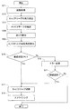
次に、上記したスプライシング装置21の動作について、図7を参照しつつ、説明する。図7は、スプライシング装置21の処理内容を示すフローチャートである。例えば、スプライシングユニット10は、ホストコンピュータ(図示略)から、部品切れとなるテープフィーダ(第二キャリアテープTc2)の情報を受信すると、その旨を表示装置24に表示する。作業者は、表示装置24の表示内容を確認し、部品切れとなるテープフィーダまで移動し、第二キャリアテープTc2に第一キャリアテープTc1をスプライシングする作業を行う。なお、スプライシング装置21内における第二キャリアテープTc2に対するスプライシングの処理は、第一キャリアテープTc1に対する処理と同様である。このため、以下の説明では、第一キャリアテープTc1に対する処理を主に説明し、第二キャリアテープTc2に対する処理の説明を適宜省略する。
次に、上記したスプライシング装置21の動作について、図7を参照しつつ、説明する。図7は、スプライシング装置21の処理内容を示すフローチャートである。例えば、スプライシングユニット10は、ホストコンピュータ(図示略)から、部品切れとなるテープフィーダ(第二キャリアテープTc2)の情報を受信すると、その旨を表示装置24に表示する。作業者は、表示装置24の表示内容を確認し、部品切れとなるテープフィーダまで移動し、第二キャリアテープTc2に第一キャリアテープTc1をスプライシングする作業を行う。なお、スプライシング装置21内における第二キャリアテープTc2に対するスプライシングの処理は、第一キャリアテープTc1に対する処理と同様である。このため、以下の説明では、第一キャリアテープTc1に対する処理を主に説明し、第二キャリアテープTc2に対する処理の説明を適宜省略する。
まず、図7のステップ(以下、単に「S」と記載する)11において、作業者によって本体制御部12の電源スイッチ12aをオン操作されると、スプライシング装置21の制御部36は、起動処理を行う。制御部36は、駆動部44を起動してスプロケット43を回転させる。制御部36は、回転角度検出部45の回転角度情報D2に基づいて、スプロケット43を原点位置に位置決めする(S11)。例えば、制御部36は、回転角度検出部45が受光状態になると、スプロケット43の回転を停止させ原点位置とする。図8は、原点位置のスプロケット43の状態を示している。図8に示すように、スプロケット43は、原点位置において、検出穴43bを回転角度検出部45によって検出される回転位置となっている。
次に、作業者は、電源を投入した後、バーコードリーダ23を用いたスプライシングベリファイを実行する。作業者は、表示装置24の表示を見てスプライシングベリファイが良好であることを確認すると、第一及び第二キャリアテープTc1,Tc2の各々を、2つの挿入口31のそれぞれに挿入する。図8に示すように、第一キャリアテープTc1は、テープ搬送路32に下面を支持された状態で搬送方向35に沿って挿入口31から係合位置Leに向かって挿入される。
図9に示すように、作業者によって挿入された第一キャリアテープTc1は、付勢部47の押圧部材47bによってスプロケット43側に押圧される。係合位置Leにおいて、スプロケット43の歯43aは、送り穴Hcに下方から挿入され、送り穴Hcに対して係合した状態となる。この状態において、制御部36は、テープ検出部41の検出情報D1に基づいて、挿入口31から第一キャリアテープTc1が挿入されたことを検出する(S12)。
制御部36は、駆動部44を駆動してスプロケット43を回転(図9における時計回り方向に回転)させ、第一キャリアテープTc1を送り穴検出部48の検査位置L2に向かって搬送する(S13)。
次に、図10に示すように、第一キャリアテープTc1の先端部が検査位置L2まで搬送される。例えば、最も先端側の送り穴Hcが検査位置L2となる。制御部36は、送り穴検出部48の送り穴位置情報D3に基づいて、検査位置L2に送り穴Hcが配置されたことを検出する(S14)。
次に、制御部36は、スプロケット43の回転角度を算出する(S15)。制御部36は、例えば、駆動部44のエンコーダの情報に基づいて、駆動部44のモータを回転させた角度を検出する。制御部36は、図8及び図9に示す原点位置を基準として、原点位置からスプロケット43を回転させた角度に基づいて、スプロケット43の回転角度を算出する。
ここで、本実施形態のスプロケット43は、例えば、図9に示す原点位置において係合位置Leの歯43aに送り穴Hcを係合させた状態から、図10に示す送り穴検出部48によって送り穴Hcを検出する状態まで回転すると、正常回転角度θ1だけ回転する。換言すれば、送り穴検出部48の検査位置L2は、歯43aに送り穴Hcが正しく係合した状態でスプロケット43を原点位置から正常回転角度θ1だけ回転させると、送り穴Hcを検出(例えば、最初に検出)する位置となっている。例えば、係合位置Leと検査位置L2との距離71は、送り穴Hcの間隔Pcの整数倍の距離となっている。これにより、制御部36は、送り穴検出部48により送り穴Hcを検出したタイミングにおけるスプロケット43の回転角度を判定することで、歯43aが送り穴Hcに係合した状態で第一キャリアテープTc1をスプロケット43により搬送している状態(以下、「正常搬送状態」という)であるか否かを判定することができる(S16)。
S16において、制御部36は、S15で算出した回転角度が正常回転角度θ1であるか否かを判定する。制御部36は、回転角度が正常回転角度θ1である場合、即ち、正常搬送状態である場合(S16:YES)、通常通りのスプライシング作業を継続する。なお、制御部36は、回転角度が正常回転角度θ1と完全に一致していなくとも、例えば、正常回転角度θ1を基準として所定の範囲内の回転角度である場合に、正常搬送状態であると判定してもよい。
制御部36は、駆動部44を駆動しスプロケット43をさらに回転させ、第一キャリアテープTc1をテープ切断位置Lcに向けて搬送する(S17)。制御部36は、切断装置38を制御して、第一キャリアテープTc1の不要部分を切断する(S17)。同様に、制御部36は、切断装置38によって第二キャリアテープTc2の不要部分を切断する(S17)。そして、制御部36は、第一及び第二キャリアテープTc1,Tc2の互いの切断面を突き合わせてスプライシングを実行する(S18)。制御部36は、スプライシングを完了させると、上部カバー21bを開け、スプライシングが完了した第一及び第二キャリアテープTc1,Tc2を取り出せる状態にする(S18)。これにより、スプライシング装置21は、送り穴Hcの中心からずれた位置で第一及び第二キャリアテープTc1,Tc2を切断することなく、正常にスプライシング作業を完了させることができる。
次に、正常搬送状態でない状態(以下、「異常搬送状態」という)について説明する。例えば、図11に示すように、第一キャリアテープTc1は、作業者によって係合位置Leまで挿入された際に、原点位置のスプロケット43の歯43aと付勢部47の押圧部材47bとの間に、送り穴Hc以外の部分(図示例では先端部)を挟まれた状態となる場合がある。特に、第一キャリアテープTc1の厚みが大きい場合には、第一キャリアテープTc1は、歯43aと押圧部材47bとで挟まれる可能性が高くなる。
この挟まれた状態でスプロケット43が原点位置から回転すると、図12に示すように、第一キャリアテープTc1は、押圧部材47b及び歯43aの間に挟まれたまま、歯43aによって送り穴Hc以外の部分を押され搬送される異常搬送状態となる。この歯43aと送り穴Hcとが係合せずに搬送される異常搬送状態では、第一キャリアテープTc1(特に先端部)は、正常搬送状態の位置からずれた位置に搬送される。その結果、スプライシング装置21は、送り穴Hcの中心からずれた位置で第一キャリアテープTc1を切断しスプライシングを実行してしまう虞がある。
ここで、異常搬送状態では、送り穴検出部48で送り穴Hcを検出したタイミングにおけるスプロケット43の回転角度は、図10に示す正常搬送状態の正常回転角度θ1とは異なる異常回転角度θ2となる(図12参照)。例えば、図11及び図12に示すように、歯43aと押圧部材47bとで第一キャリアテープTc1の先端部を挟んだ場合、スプロケット43は、最も先端側の送り穴Hcよりもさらに先端側の位置に歯43aを当接した状態(原点位置)から回転を開始する。この場合、送り穴検出部48で送り穴Hcを検出したタイミングにおける異常回転角度θ2は、正常回転角度θ1(図10参照)に比べて大きい角度となる。
一方で、上記した図11及び図12の場合とは異なり、最も先端側の送り穴Hcが係合位置Leよりも下流側(テープ切断位置Lc側)になるまで、第一キャリアテープTc1の先端がテープ搬送路32の奥まで作業者によって挿入された場合を考える。この場合、原点位置のスプロケット43は、送り穴Hcの上流側(挿入口31側)の部分を歯43aと押圧部材47bとで挟む状態となる。その結果、異常回転角度θ2は、上記した場合とは逆に、正常回転角度θ1(図10参照)に比べて小さい角度となる。
そこで、制御部36は、図7に示すS16において、S15で算出した回転角度が正常回転角度θ1からずれて異常回転角度θ2となっていた場合、即ち、歯43aと送り穴Hcとが係合していない異常搬送状態である場合(S16:NO)、エラー処理を実行する(S19)。例えば、制御部36は、エラー情報ER(図6参照)を表示装置24へ送信し、表示装置24にエラー表示を行う。なお、異常搬送状態(エラー)の通知方法は、表示装置24に表示する方法に限らず、警告音を鳴らすなどの方法でもよい。
次に、制御部36は、スプライシング作業を継続するか否かを判定する(S21)。図11及び図12に示す異常搬送状態であっても、作業者は、スプライシング作業を継続し、スプライシングを完了させたい場合もある。そこで、例えば、制御部36は、表示装置24にスプライシング作業を継続するか否かの選択画面を表示する(S21)。なお、この際に、制御部36は、異常回転角度θ2のずれの大きさなど、選択画面の他に作業者の判断に有用な情報を表示装置24に表示してもよい。
作業者が作業の継続を選択した場合(S21:YES)、制御部36は、S17、S18の処理を実行し、スプライシング作業を完了させる。これにより、仮に、異常搬送状態であっても、作業者の判断により、スプライシング作業の継続の有無を選択することができる。
一方で、作業者が作業の中止を選択した場合(S21:NO)、制御部36は、スプライシング作業を中止して上部カバー21bを開け、第一及び第二キャリアテープTc1,Tc2を取り出せる状態にする。これにより、作業者は、第一及び第二キャリアテープTc1,Tc2を用いて再度スプライシング作業を行うなど、適切な対応を実行することができる。
(5.実施形態の構成による効果)
上記した実施形態のスプライシング装置21は、送り穴Hcと部品収納用のキャビティCtとをそれぞれ一定の間隔に設けた第一キャリアテープTc1(キャリアテープ)をスプライシングするスプライシング装置である。スプライシング装置21は、上部カバー21b及び本体部21a(筐体)と、上部カバー21b及び本体部21aの内外を連通し、第一キャリアテープTc1を挿入可能な挿入口31と、上部カバー21b及び本体部21a内に設けられ、挿入口31から挿入された第一キャリアテープTc1を支持するテープ搬送路32と、本体部21aに対して回転可能に支持され、テープ搬送路32に支持された第一キャリアテープTc1の送り穴Hcに係合する歯43aを有するスプロケット43と、スプロケット43を回転させ、第一キャリアテープTc1をテープ搬送路32に沿って搬送する駆動部44と、スプロケット43の回転角度に係わる回転角度情報D2を検出する回転角度検出部45と、第一キャリアテープTc1の搬送にともなって変更される送り穴Hcの位置に係わる送り穴位置情報D3を検出する送り穴検出部48と、回転角度情報D2及び送り穴位置情報D3を入力する制御部36と、を備える。制御部36は、回転角度情報D2に基づくスプロケット43の回転角度と、送り穴位置情報D3に基づく送り穴Hcの位置と、の関係に基づいて、送り穴Hcに歯43aが係合した状態で第一キャリアテープTc1がスプロケット43により搬送されている正常搬送状態であるか否かを判定する(図7のS16)。
上記した実施形態のスプライシング装置21は、送り穴Hcと部品収納用のキャビティCtとをそれぞれ一定の間隔に設けた第一キャリアテープTc1(キャリアテープ)をスプライシングするスプライシング装置である。スプライシング装置21は、上部カバー21b及び本体部21a(筐体)と、上部カバー21b及び本体部21aの内外を連通し、第一キャリアテープTc1を挿入可能な挿入口31と、上部カバー21b及び本体部21a内に設けられ、挿入口31から挿入された第一キャリアテープTc1を支持するテープ搬送路32と、本体部21aに対して回転可能に支持され、テープ搬送路32に支持された第一キャリアテープTc1の送り穴Hcに係合する歯43aを有するスプロケット43と、スプロケット43を回転させ、第一キャリアテープTc1をテープ搬送路32に沿って搬送する駆動部44と、スプロケット43の回転角度に係わる回転角度情報D2を検出する回転角度検出部45と、第一キャリアテープTc1の搬送にともなって変更される送り穴Hcの位置に係わる送り穴位置情報D3を検出する送り穴検出部48と、回転角度情報D2及び送り穴位置情報D3を入力する制御部36と、を備える。制御部36は、回転角度情報D2に基づくスプロケット43の回転角度と、送り穴位置情報D3に基づく送り穴Hcの位置と、の関係に基づいて、送り穴Hcに歯43aが係合した状態で第一キャリアテープTc1がスプロケット43により搬送されている正常搬送状態であるか否かを判定する(図7のS16)。
これによれば、制御部36は、スプロケット43の回転角度と送り穴Hcの位置との関係に基づいて、正常搬送状態であるか否かを判定する。これにより、制御部36は、スプロケット43の歯43aが第一キャリアテープTc1の送り穴Hcに係合していないにも係わらず第一キャリアテープTc1を搬送している異常搬送状態を検出できる。この場合、制御部36は、例えば、スプライシング作業の中止や作業者への通知など、適切な処理を実施できる。その結果、第一キャリアテープTc1が所望の位置からずれた位置で切断される事態の発生を抑制できる。
さらに、送り穴検出部48は、正常搬送状態においてスプロケット43を原点位置から正常回転角度θ1まで回転させた場合に、搬送した第一キャリアテープTc1の送り穴Hcを検出する位置に設けられている。制御部36は、送り穴検出部48により送り穴Hcを検出したタイミングにおけるスプロケット43の回転角度が正常回転角度θ1と一致する場合に、正常搬送状態であると判定する。
これによれば、送り穴検出部48は、スプロケット43を原点位置から正常回転角度θ1まで回転させた場合に、送り穴Hcを検出する位置に設けられる。このため、制御部36は、送り穴検出部48により送り穴Hcを検出したタイミングの回転角度を、正常回転角度θ1と比較することで、正常搬送状態であるか否かを判定できる。これにより、制御部36は、正常搬送状態であるか否かを容易な処理で判定することが可能となる。
さらに、送り穴検出部48は、第一キャリアテープTc1の搬送方向35において、歯43aと送り穴Hcとが係合する係合位置Leに比べて下流側の位置で送り穴Hcを検出する。
送り穴Hcに歯43aが係合せず、送り穴Hc以外の部分を歯43aで押して第一キャリアテープTc1を搬送した場合(図11及び図12参照)、送り穴Hcは、正常搬送状態(図9及び図10参照)の位置からずれる。この送り穴Hcのずれは、係合位置Leの上流側に比べて下流側の方がより顕著に発生する可能性がある。このため、送り穴検出部48は、係合位置Leよりも下流側で送り穴Hcを検出することで、送り穴Hcの位置ずれの発生、即ち、正常搬送状態であるか否かを精度よく検出することが可能となる。
さらに、スプライシング装置21は、第一キャリアテープTc1をスプロケット43側に付勢し、送り穴Hcに歯43aを係合させる付勢部47を、さらに備える。
これによれば、挿入口31から挿入された第一キャリアテープTc1は、付勢部47によってスプロケット43側に付勢されることで、送り穴Hcに歯43aを係合し易くなる。一方で、付勢部47によって付勢した場合、第一キャリアテープTc1は、付勢部47とスプロケット43の歯43aとの間で挟まれ、送り穴Hcに歯43aが係合しないまま搬送され異常搬送状態となる虞がある。このため、付勢部47を備えるスプライシング装置21において、正常搬送状態を判定することは極めて有効である。
さらに、制御部36は、正常搬送状態でないと判定した場合、その旨を通知する(図7のS19)。
これによれば、作業者は、スプライシング装置21からの通知によって、異常搬送状態の発生を認識することができる。作業者は、第一キャリアテープTc1を取り出して、再度スプライシング作業を実施するなど、適切な対応を行うことができる。
(6.実施形態の変形態様)
上記実施形態では、制御部36は、原点位置からの回転角度に基づいて正常搬送状態を判定したが、正常搬送状態の判定方法はこれに限らない。例えば、スプロケット43の歯43aは、間隔Pcでスプロケット43の外周に設けられている。また、スプロケット43が所定角度だけ回転するごとに、係合位置Leには、異なる歯43aが配置される。例えば、スプロケット43の外周に歯43aが間隔Pcごとに30個設けられた場合を考える。この場合、スプロケット43が12度だけ回転するごとに、係合位置Leには、異なる歯43aが配置される。そこで、制御部36は、例えば、S16の判定において、送り穴検出部48で送り穴Hcを検出したタイミングの回転角度が12度の整数倍と一致していた場合に、正常搬送状態であると判定してもよい。
上記実施形態では、制御部36は、原点位置からの回転角度に基づいて正常搬送状態を判定したが、正常搬送状態の判定方法はこれに限らない。例えば、スプロケット43の歯43aは、間隔Pcでスプロケット43の外周に設けられている。また、スプロケット43が所定角度だけ回転するごとに、係合位置Leには、異なる歯43aが配置される。例えば、スプロケット43の外周に歯43aが間隔Pcごとに30個設けられた場合を考える。この場合、スプロケット43が12度だけ回転するごとに、係合位置Leには、異なる歯43aが配置される。そこで、制御部36は、例えば、S16の判定において、送り穴検出部48で送り穴Hcを検出したタイミングの回転角度が12度の整数倍と一致していた場合に、正常搬送状態であると判定してもよい。
また、上記実施形態では、制御部36は、送り穴検出部48の送り穴位置情報D3を用いて送り穴Hcの位置を判定したが、これに限らない。例えば、制御部36は、キャビティ検出部49のキャビティ位置情報D4を用いて、送り穴Hcの位置を判定してもよい。一般的に、送り穴Hcの間隔Pcと、キャビティCtの間隔Pcとは、第一キャリアテープTc1の規格等によって定められ、一定の関係性を有している。このため、制御部36は、キャビティ位置情報D4から送り穴Hcの位置を検出し、回転角度を判定するタイミングを決定してもよい。この場合、作業者は、例えば、送り穴Hcの間隔Pcと、キャビティCtの間隔Pcとの関係性を判断するための補助的な情報(規格等)を表示装置24から入力してもよい。これにより、制御部36は、表示装置24から入力された情報に基づいて、キャビティ位置情報D4から送り穴Hcの位置をより精度よく検出することが可能となる。なお、この場合、スプライシング装置21は、キャビティ検出部49を本願における送り穴検出部として用いることができるため、上記実施形態の送り穴検出部48を備えない構成でもよい。
また、制御部36は、回転角度検出部45の回転角度情報D2に基づいて原点位置を決定し、その原点位置からの回転角度に基づいてスプロケット43の回転角度を検出する構成であった。しかしながら、スプロケット43の回転角度を検出する構成は、これに限らない。例えば、回転角度検出部45は、スプロケット43の回転角度を回転角度情報D2として出力するエンコーダでもよい。この場合、制御部36は、回転角度検出部45の回転角度情報D2のみでスプロケット43の回転角度を検出できる。
また、上記実施形態において、送り穴検出部48を、係合位置Leの下流に設けたが、上流に設けてもよい。この場合、制御部36は、例えば、テープ検出部41で第一キャリアテープTc1を検出してから送り穴検出部48によって所定の個数の送り穴Hcを検出したタイミング(係合位置Leから一定量だけ搬送したタイミング)で、回転角度の判定(S16)を実行してもよい。
また、スプライシング装置21は、付勢部47を備えない構成でもよい。例えば、スプライシング装置21は、送り穴Hcを歯43aに係合させるように、第一キャリアテープTc1をスプロケット43側に案内する案内溝を備えてもよい。
また、上記実施形態において、送り穴検出部48を、係合位置Leの下流に設けたが、上流に設けてもよい。この場合、制御部36は、例えば、テープ検出部41で第一キャリアテープTc1を検出してから送り穴検出部48によって所定の個数の送り穴Hcを検出したタイミング(係合位置Leから一定量だけ搬送したタイミング)で、回転角度の判定(S16)を実行してもよい。
また、スプライシング装置21は、付勢部47を備えない構成でもよい。例えば、スプライシング装置21は、送り穴Hcを歯43aに係合させるように、第一キャリアテープTc1をスプロケット43側に案内する案内溝を備えてもよい。
また、上記実施形態では、制御部36は、第一及び第二キャリアテープTc1,Tc2の両方について正常搬送状態を判定したが、どちらか一方のキャリアテープ、例えば、補給用の第一キャリアテープTc1の正常搬送状態のみを判定してもよい。この場合、スプライシング装置21は、第二キャリアテープTc2用の送り穴検出部48を備えなくともよい。
また、制御部36は、スプライシング作業を継続するか否かの判定(S21)を実行しない構成でもよい。この場合、制御部36は、S19で表示装置24にエラー表示をした後、図7の処理を終了してもよい。
また、制御部36は、スプライシング作業を継続するか否かの判定(S21)を実行しない構成でもよい。この場合、制御部36は、S19で表示装置24にエラー表示をした後、図7の処理を終了してもよい。
21:スプライシング装置、21a:本体部(筐体)、21b:上部カバー(筐体)、31:挿入口、32:テープ搬送路、35:搬送方向、36:制御部、43:スプロケット、43a:歯、44:駆動部、45:回転角度検出部、47:付勢部、48:送り穴検出部、Ct:キャビティ、D2:回転角度情報、D3:送り穴位置情報、Hc:送り穴、Le:係合位置、Tc1:第一キャリアテープ(キャリアテープ)、Tc2:第二キャリアテープ(キャリアテープ)、θ1:正常回転角度。
Claims (5)
- 送り穴と部品収納用のキャビティとをそれぞれ一定の間隔に設けたキャリアテープをスプライシングするスプライシング装置であって、
筐体と、
前記筐体の内外を連通し、前記キャリアテープを挿入可能な挿入口と、
前記筐体内に設けられ、前記挿入口から挿入された前記キャリアテープを支持するテープ搬送路と、
前記筐体に対して回転可能に支持され、前記テープ搬送路に支持された前記キャリアテープの前記送り穴に係合する歯を有するスプロケットと、
前記スプロケットを回転させ、前記キャリアテープを前記テープ搬送路に沿って搬送する駆動部と、
前記スプロケットの回転角度に係わる回転角度情報を検出する回転角度検出部と、
前記キャリアテープの搬送にともなって変更される前記送り穴の位置に係わる送り穴位置情報を検出する送り穴検出部と、
前記回転角度情報及び前記送り穴位置情報を入力する制御部と、
を備え、
前記制御部は、
前記回転角度情報に基づく前記スプロケットの前記回転角度と、前記送り穴位置情報に基づく前記送り穴の前記位置と、の関係に基づいて、前記送り穴に前記歯が係合した状態で前記キャリアテープが前記スプロケットにより搬送されている正常搬送状態であるか否かを判定する、スプライシング装置。 - 前記送り穴検出部は、前記正常搬送状態において前記スプロケットを原点位置から正常回転角度まで回転させた場合に、搬送した前記キャリアテープの前記送り穴を検出する位置に設けられており、
前記制御部は、前記送り穴検出部により前記送り穴を検出したタイミングにおける前記スプロケットの前記回転角度が前記正常回転角度と一致する場合に、前記正常搬送状態であると判定する、請求項1に記載のスプライシング装置。 - 前記送り穴検出部は、前記キャリアテープの搬送方向において、前記歯と前記送り穴とが係合する係合位置に比べて下流側の位置で前記送り穴を検出する、請求項1又は2に記載のスプライシング装置。
- 前記キャリアテープを前記スプロケット側に付勢し、前記送り穴に前記歯を係合させる付勢部を、さらに備える、請求項1乃至3の何れか一項に記載のスプライシング装置。
- 前記制御部は、前記正常搬送状態でないと判定した場合、その旨を通知する、請求項1乃至4の何れか一項に記載のスプライシング装置。
Priority Applications (3)
| Application Number | Priority Date | Filing Date | Title |
|---|---|---|---|
| CN201680090138.2A CN109845429B (zh) | 2016-10-20 | 2016-10-20 | 拼接装置 |
| JP2018546097A JP6745892B2 (ja) | 2016-10-20 | 2016-10-20 | スプライシング装置 |
| PCT/JP2016/081032 WO2018073924A1 (ja) | 2016-10-20 | 2016-10-20 | スプライシング装置 |
Applications Claiming Priority (1)
| Application Number | Priority Date | Filing Date | Title |
|---|---|---|---|
| PCT/JP2016/081032 WO2018073924A1 (ja) | 2016-10-20 | 2016-10-20 | スプライシング装置 |
Publications (1)
| Publication Number | Publication Date |
|---|---|
| WO2018073924A1 true WO2018073924A1 (ja) | 2018-04-26 |
Family
ID=62019098
Family Applications (1)
| Application Number | Title | Priority Date | Filing Date |
|---|---|---|---|
| PCT/JP2016/081032 Ceased WO2018073924A1 (ja) | 2016-10-20 | 2016-10-20 | スプライシング装置 |
Country Status (3)
| Country | Link |
|---|---|
| JP (1) | JP6745892B2 (ja) |
| CN (1) | CN109845429B (ja) |
| WO (1) | WO2018073924A1 (ja) |
Cited By (1)
| Publication number | Priority date | Publication date | Assignee | Title |
|---|---|---|---|---|
| JP2022090460A (ja) * | 2020-12-07 | 2022-06-17 | 株式会社Fuji | テープ切断処理装置、テープ自動装填装置、及びスプライシング装置 |
Citations (5)
| Publication number | Priority date | Publication date | Assignee | Title |
|---|---|---|---|---|
| JP2008256641A (ja) * | 2007-04-09 | 2008-10-23 | Matsushita Electric Ind Co Ltd | 面導光円板、光学式エンコーダおよびテープフィーダ |
| WO2014102965A1 (ja) * | 2012-12-27 | 2014-07-03 | 富士機械製造株式会社 | スプライシング装置およびスプライシングテープ検知方法 |
| JP2014225592A (ja) * | 2013-05-17 | 2014-12-04 | パナソニック株式会社 | スプライシング装置及びスプライシング装置における部品テープの送り方法 |
| JP2015176970A (ja) * | 2014-03-14 | 2015-10-05 | オムロン株式会社 | キャリアテープ中の部品の有無を検出する方法、センサモジュール、スプライシング装置、及び、部品実装機 |
| JP2016127217A (ja) * | 2015-01-08 | 2016-07-11 | パナソニックIpマネジメント株式会社 | 電子部品供給装置ならびに電子部品供給装置における部品供給テープの処理方法 |
Family Cites Families (4)
| Publication number | Priority date | Publication date | Assignee | Title |
|---|---|---|---|---|
| JP6153616B2 (ja) * | 2013-08-26 | 2017-06-28 | 富士機械製造株式会社 | フィーダ |
| WO2015121928A1 (ja) * | 2014-02-12 | 2015-08-20 | 富士機械製造株式会社 | スプライシング装置およびスプライシング方法 |
| KR101536570B1 (ko) * | 2014-06-12 | 2015-07-14 | 하재복 | 캐리어 테이프용 스플라이싱 장치 |
| CN205546418U (zh) * | 2016-03-29 | 2016-08-31 | 北亚美亚电子科技(深圳)有限公司 | 一种新型料带衔接组件 |
-
2016
- 2016-10-20 CN CN201680090138.2A patent/CN109845429B/zh active Active
- 2016-10-20 JP JP2018546097A patent/JP6745892B2/ja active Active
- 2016-10-20 WO PCT/JP2016/081032 patent/WO2018073924A1/ja not_active Ceased
Patent Citations (5)
| Publication number | Priority date | Publication date | Assignee | Title |
|---|---|---|---|---|
| JP2008256641A (ja) * | 2007-04-09 | 2008-10-23 | Matsushita Electric Ind Co Ltd | 面導光円板、光学式エンコーダおよびテープフィーダ |
| WO2014102965A1 (ja) * | 2012-12-27 | 2014-07-03 | 富士機械製造株式会社 | スプライシング装置およびスプライシングテープ検知方法 |
| JP2014225592A (ja) * | 2013-05-17 | 2014-12-04 | パナソニック株式会社 | スプライシング装置及びスプライシング装置における部品テープの送り方法 |
| JP2015176970A (ja) * | 2014-03-14 | 2015-10-05 | オムロン株式会社 | キャリアテープ中の部品の有無を検出する方法、センサモジュール、スプライシング装置、及び、部品実装機 |
| JP2016127217A (ja) * | 2015-01-08 | 2016-07-11 | パナソニックIpマネジメント株式会社 | 電子部品供給装置ならびに電子部品供給装置における部品供給テープの処理方法 |
Cited By (2)
| Publication number | Priority date | Publication date | Assignee | Title |
|---|---|---|---|---|
| JP2022090460A (ja) * | 2020-12-07 | 2022-06-17 | 株式会社Fuji | テープ切断処理装置、テープ自動装填装置、及びスプライシング装置 |
| JP7655718B2 (ja) | 2020-12-07 | 2025-04-02 | 株式会社Fuji | テープ切断処理装置、テープ自動装填装置、及びスプライシング装置 |
Also Published As
| Publication number | Publication date |
|---|---|
| JP6745892B2 (ja) | 2020-08-26 |
| CN109845429B (zh) | 2020-11-03 |
| CN109845429A (zh) | 2019-06-04 |
| JPWO2018073924A1 (ja) | 2019-08-15 |
Similar Documents
| Publication | Publication Date | Title |
|---|---|---|
| CN104221487B (zh) | 自动拼接装置 | |
| JP5897112B2 (ja) | スプライシング装置およびスプライシング方法 | |
| EP2941112B1 (en) | Splicing-tape feed device and feed method | |
| CN104221486B (zh) | 自动拼接装置 | |
| US10384901B2 (en) | Splicing device and tape detecting method using the same | |
| CN107006146B (zh) | 带的自动检测装置及自动检测方法 | |
| JP6603705B2 (ja) | 自動スプライシング装置 | |
| JP7058172B2 (ja) | テープ自動搬送装置 | |
| JP6745892B2 (ja) | スプライシング装置 | |
| CN104255088A (zh) | 拼接带 | |
| WO2016157437A1 (ja) | 自動スプライシング装置及び部品実装機 | |
| JP6966869B2 (ja) | スプライシング装置 | |
| JP6279949B2 (ja) | スプライシング装置におけるテープ切断位置の補正方法 | |
| EP3280239B1 (en) | Automatic splicing device | |
| WO2016151745A1 (ja) | スプライシング装置 | |
| JP6641384B2 (ja) | スプライシング装置 | |
| JP2020010045A (ja) | 自動スプライシング方法 | |
| JP2017074995A (ja) | 自動スプライシング装置 | |
| JP6928173B2 (ja) | テープ送り装置およびテープ送り方法 | |
| CN108432360B (zh) | 拼接装置 | |
| JP2020113797A (ja) | フィーダ自動交換方法 |
Legal Events
| Date | Code | Title | Description |
|---|---|---|---|
| 121 | Ep: the epo has been informed by wipo that ep was designated in this application |
Ref document number: 16919275 Country of ref document: EP Kind code of ref document: A1 |
|
| ENP | Entry into the national phase |
Ref document number: 2018546097 Country of ref document: JP Kind code of ref document: A |
|
| NENP | Non-entry into the national phase |
Ref country code: DE |
|
| 122 | Ep: pct application non-entry in european phase |
Ref document number: 16919275 Country of ref document: EP Kind code of ref document: A1 |