WO2018070151A1 - ステージ装置 - Google Patents
ステージ装置 Download PDFInfo
- Publication number
- WO2018070151A1 WO2018070151A1 PCT/JP2017/032368 JP2017032368W WO2018070151A1 WO 2018070151 A1 WO2018070151 A1 WO 2018070151A1 JP 2017032368 W JP2017032368 W JP 2017032368W WO 2018070151 A1 WO2018070151 A1 WO 2018070151A1
- Authority
- WO
- WIPO (PCT)
- Prior art keywords
- axis
- guide
- slider
- axis guide
- posture maintaining
- Prior art date
- Legal status (The legal status is an assumption and is not a legal conclusion. Google has not performed a legal analysis and makes no representation as to the accuracy of the status listed.)
- Ceased
Links
Images


Classifications
-
- F—MECHANICAL ENGINEERING; LIGHTING; HEATING; WEAPONS; BLASTING
- F16—ENGINEERING ELEMENTS AND UNITS; GENERAL MEASURES FOR PRODUCING AND MAINTAINING EFFECTIVE FUNCTIONING OF MACHINES OR INSTALLATIONS; THERMAL INSULATION IN GENERAL
- F16C—SHAFTS; FLEXIBLE SHAFTS; ELEMENTS OR CRANKSHAFT MECHANISMS; ROTARY BODIES OTHER THAN GEARING ELEMENTS; BEARINGS
- F16C32/00—Bearings not otherwise provided for
- F16C32/06—Bearings not otherwise provided for with moving member supported by a fluid cushion formed, at least to a large extent, otherwise than by movement of the shaft, e.g. hydrostatic air-cushion bearings
Definitions
- the present invention relates to a stage apparatus.
- a stage apparatus for positioning an object in a first direction and a second direction orthogonal to the first direction is known.
- a stage apparatus called a stack type in which there is one guide in each of the X-axis direction and the Y-axis direction has been proposed (for example, Patent Document 1).
- the stack type stage apparatus includes a first slider, a first guide for guiding the movement of the first slider in the first direction, a second slider for supporting the first guide, and a second slider in the second direction.
- a second guide for guiding the movement is provided.
- the present invention has been made in view of such circumstances, and an object of the present invention is to provide a stage apparatus capable of suppressing the occurrence of galling that the slider contacts the guide.
- a stage apparatus includes a first slider, a first guide that guides the movement of the first slider in the first direction, and a second slider that supports the first guide.
- a second guide for guiding the movement of the second slider in the second direction, and at least one posture maintaining member for applying a posture control force for maintaining the posture of the first guide to the first guide.
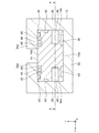
- FIG. 3 is a sectional view taken along line AA in FIG. 2. It is sectional drawing which shows one of the attitude
- FIG. 1 is a perspective view showing a stage apparatus 100 according to an embodiment.
- the X-axis guide 12 (described later) extends in the X-axis direction
- the direction orthogonal to the X-axis direction and the Y-axis guide 16 (described later) extends in the Y direction.
- An XYZ orthogonal coordinate system is defined in which the axial direction and the direction orthogonal to both are the Z-axis direction.
- the stage apparatus 100 is called a stack type XY stage, and positions an object in the X-axis direction (first direction) and the Y-axis direction (second direction orthogonal to the first direction).
- the stage apparatus 100 includes a base frame 10, an X-axis guide 12, an X-axis slider 14, a Y-axis guide 16, a Y-axis slider 18, a table 20, two side guides 22, and two posture maintaining members. 26 and a control unit 30 (not shown in FIG. 1).
- a base frame 10 an X-axis guide 12, an X-axis slider 14, a Y-axis guide 16, a Y-axis slider 18, a table 20, two side guides 22, and two posture maintaining members. 26 and a control unit 30 (not shown in FIG. 1).
- the side where the X-axis guide 12 is provided with respect to the Y-axis guide 16 in the Z-axis direction will be described as the upper side.
- the Y-axis guide 16 is a long member and is supported by the base frame 10.
- the Y-axis slider 18 is guided by the Y-axis guide 16 and moves in the Y-axis direction.
- the X-axis guide 12 is a long member similar to the Y-axis guide 16 and is supported by the Y-axis slider 18. Therefore, the X-axis guide 12 and thus the X-axis slider 14 move in the Y-axis direction as the Y-axis slider 18 moves in the Y-axis direction.
- the X-axis slider 14 is guided by the X-axis guide 12 and moves in the X-axis direction.
- the table 20 is fixed to the X-axis slider 14.
- a processing object such as a semiconductor wafer is placed on the table 20.
- the table 20 can be moved in the XY direction so that the object can be positioned in the XY direction.
- FIG. 2 shows a cross section of the X-axis guide 12 and the X-axis slider 14 cut along a plane orthogonal to the X-axis direction. Note that the configuration of the X-axis guide 12 and the X-axis slider 14 will be described as a representative, but the same description applies to the Y-axis guide 16 and the Y-axis slider 18.
- the X-axis guide 12 includes a bottom wall 32, a first side wall 34, and a second side wall 36.
- the bottom wall 32 is a flat plate-like member that is long in the X-axis direction, and is provided so that two main surfaces face the Z-axis direction.
- the first side wall 34 is a standing wall that is long in the X-axis direction, and is erected at one end in the Y-axis direction of the upper surface (ie, one main surface) of the bottom wall 32.
- the second side wall 36 is a standing wall that is long in the X-axis direction, and is erected on the other end in the Y-axis direction of the upper surface of the bottom wall 32 so as to face the first side wall 34 in the Y-axis direction.
- the first side wall 34 and the second side wall 36 respectively have a first extension part 34a and a second extension part 36a that extend toward each other. Accordingly, the first side wall 34 and the second side wall 36 have an L-shaped cross-sectional shape.
- the X-axis slider 14 is a rectangular parallelepiped member, and is housed inside the X-axis guide 12, that is, between the first side wall 34, the second side wall 36, and the bottom wall 32.
- One or a plurality of air pads 40 are formed on each surface of the X-axis slider 14 facing the X-axis guide 12, that is, the bottom surface 14a, the first side surface 14b, the second side surface 14c, and the top surface 14d.
- the air pad 40 ejects a high-pressure gas supplied from an air supply system (not shown), and forms a high-pressure gas layer between the air pad 40 and the X-axis guide 12.
- an air supply system not shown
- An air servo chamber 48 for driving the X-axis guide 12 is formed on the first side surface 14b facing the first side wall 34 and the second side surface 14c facing the second side wall 36. That is, in the present embodiment, two air servo chambers 48 are formed in the X-axis slider 14. Thereby, the rotation of the X-axis slider 14 around the Z-axis can be controlled.
- Exhaust grooves 42, 44, 46 for differential exhaust are formed on each surface of the X-axis slider 14 so as to surround the air pad 40.
- the exhaust groove 42 is open to the atmosphere.
- the exhaust groove 42 may be connected to an exhaust pump (not shown).
- the exhaust grooves 44 and 46 are respectively connected to an exhaust pump (not shown) for setting the pressure in the exhaust groove to a low vacuum pressure level and a medium vacuum pressure level, and the air pad 40 and the air servo chamber of the X-axis slider 14.
- the compressed gas supplied from 48 to the internal space is exhausted to the outside.
- the stage apparatus 100 can be used even in a vacuum environment.
- FIG. 3 is a cross-sectional view taken along line AA in FIG.
- the stage apparatus 100 further includes a partition wall 56.
- the gap between the X-axis guide 12 and the X-axis slider 14 and the gap between the partition wall 56 and the air servo chamber 48 are exaggerated. In practice, for example, these gaps are on the order of several microns.
- the partition wall 56 is fixed to the X-axis guide 12 and divides the air servo chamber 48 of the X-axis slider 14 into two air servo chambers 48A and 48B in the X-axis direction.
- the two air servo chambers 48A and 48B are connected to air supply systems 50A and 50B for allowing compressed gas to enter and exit, respectively.
- Air supply systems 50A and 50B include servo valves 52A and 52B and compressed gas supply sources 54A and 54B, respectively.
- the X-axis slider 14 When the compressed gas is supplied to the air pad 40, the X-axis slider 14 slightly floats with respect to the X-axis guide 12 as described above. In this state, for example, when compressed gas is supplied to the air servo chamber 48A and the compressed gas is discharged from the air servo chamber 48B, the partition wall 56 acts as a piston and the X-axis slider 14 moves to the left in the drawing. In this way, the X-axis slider 14 can be moved to an arbitrary position with respect to the X-axis guide 12 by controlling the opening degree of the servo valves 52A and 52B.
- the two side guides 22 are long members.
- the two side guides are supported by the base frame 10 so that their longitudinal directions coincide with the Y-axis direction and the Y-axis guide 16 is positioned between them in the X-axis direction.
- the planar surface is applied to the sliding surface 22 a that is the upper surface of the side guide 22.
- the sliding surfaces 22a of the two side guides 22 are formed to have the same height, that is, to overlap each other when viewed from the X-axis direction.
- the two sliding surfaces 22a are formed to be parallel to the Y-axis guide 16 (more specifically, for example, the upper surface of the bottom wall 32 of the Y-axis guide 16) when viewed from the X-axis direction. .
- the two posture maintaining members 26 are fixed to the lower surface of the X-axis guide 12 (that is, the lower surface of the bottom wall 32) 12a.
- the two attitude maintaining members 26 are located on opposite sides of the supported portion of the X-axis guide 12 supported by the Y-axis slider 18 and above the sliding surface 22 a of the side guide 22. It is fixed to the lower surface 12 a of the X-axis guide 12.
- the two posture maintaining members 26 are fixed to both ends in the X-axis direction of the lower surface 12 a of the X-axis guide 12.
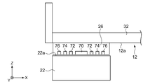
- FIG. 4 is a cross-sectional view showing one of the posture maintaining members 26 and the periphery thereof.
- FIG. 4 shows a cross section cut along a plane orthogonal to the Y-axis direction.
- the other posture maintaining member 26 is similarly configured.
- the posture maintaining member 26 includes an air pad 70 in the present embodiment, and jets high-pressure gas supplied from an air supply system (not shown) to the sliding surface 22a. Due to the repulsive force, an upward force is applied to the posture maintaining member 26 and thus the X-axis guide 12.
- differential posture exhaust grooves 72, 74, and 76 are formed in the posture maintaining member 26 so as to surround the air pad 70.
- the exhaust grooves 72, 74, and 76 are configured similarly to the exhaust grooves 42, 44, and 46, respectively.
- the stage apparatus 100 can be used even in a vacuum environment.
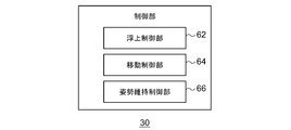
- FIG. 5 is a block diagram showing the function and configuration of the control unit 30.
- Each block shown here can be realized by hardware such as a computer CPU (central processing unit) or a device such as a computer, and software can be realized by a computer program or the like.
- the functional block realized by those cooperation is drawn. Therefore, it is understood by those skilled in the art who have touched this specification that these functional blocks can be realized in various forms by a combination of hardware and software.
- the control unit 30 includes a flying control unit 62 that controls the flow rate of the compressed gas ejected from the air pad 40 to float the X-axis slider 14 and the Y-axis slider 18, and an air servo that moves the X-axis slider 14 and the Y-axis slider 18.
- a movement control unit 64 that controls the flow rate of the compressed gas supplied to the chamber 48 and a posture maintenance control unit 66 that controls the flow rate of the gas ejected from the air pad 70 of the posture maintaining member 26 in order to maintain the posture of the X-axis guide 12. And including.
- a flying control unit 62 that controls the flow rate of the compressed gas ejected from the air pad 40 to float the X-axis slider 14 and the Y-axis slider 18, and an air servo that moves the X-axis slider 14 and the Y-axis slider 18.
- a movement control unit 64 that controls the flow rate of the compressed gas supplied to the chamber 48 and a posture maintenance control unit 66 that controls the flow rate of
- the attitude maintenance control unit 66 may use another way of saying that the upward force can obtain a sufficiently high floating rigidity against a load variation that would occur in the X-axis guide 12 due to the movement of the X-axis slider 14. Then, the flow rate of the gas ejected from the air pad 70 of the posture maintaining member 26 is controlled so that the sinking of the X-axis guide 12 due to the load fluctuation can be suppressed or prevented.
- the two attitude maintaining members 26 are fixed to the lower surface 12a of the X-axis guide 12, and gas is ejected from the attitude maintaining member 26 to the sliding surface 22a.
- an upward force is applied to the posture maintaining member 26 and thus the X-axis guide 12.
- the X-axis slider 14 moves in the X-axis direction along the X-axis guide 12
- a load change occurs in the X-axis guide 12
- the X-axis guide 12 tilts around the Y-axis direction to support the X-axis guide 12.
- a moment around the Y-axis guide 16 may be generated in the Y-axis slider 18 that performs this operation.
- galling may occur where the Y-axis slider 18 contacts the Y-axis guide 16.
- the two posture maintaining members 26 prevent the X-axis guide 12 from sinking due to upward force on the X-axis guide 12, for example, load variation occurring in the X-axis guide 12. The upward force that can be done works.
- the slider includes the exhaust grooves 42, 44, 46 for exhausting the compressed gas supplied from the air pad 40 and the air servo chamber 48 to the outside.
- the posture maintaining member 26 includes exhaust grooves 72, 74, and 76 for exhausting compressed gas supplied from the air pad 70 to the outside.
- stage device has been described above.
- This embodiment is an exemplification, and it is understood by those skilled in the art that various modifications can be made to the combination of each component, and such modifications are also within the scope of the present invention. Also, combinations of the embodiments are possible.
- the posture maintenance control unit 66 ejects the air pads 70 of the two posture maintenance control units 66 according to the speed at which the X-axis guide 12 moves, that is, according to the magnitude of the load fluctuation generated in the X-axis slider 14.
- the gas flow rate may be adjusted.
- the stage apparatus 100 may include only one posture maintaining member 26.
- the posture maintaining member 26 is naturally fixed only to one side of the supported portion of the X-axis guide 12.
- the flow rate of the gas ejected by the posture maintaining member 26 is increased, and the opposite is true.
- the flow rate of the gas ejected by the posture maintaining member 26 may be reduced or the gas ejection may be stopped.
- the stage apparatus 100 may include three or more posture maintaining members 26. In this case, even if all the posture maintaining members 26 are fixed to only one side of the supported portion of the X-axis guide 12, a part of the posture maintaining member 26 is fixed to one side of the supported portion of the X-axis guide 12. The rest may be fixed to the other side of the supported part.
- the posture maintaining member 26 has been described as including the air pad 70 that ejects gas, but is not limited thereto.
- the posture maintaining member 26 may be an air pad that sucks gas.
- the load fluctuation that will occur in the X-axis guide 12 due to the movement of the X-axis slider 14 and the floating rigidity of the air pad of the posture maintaining member 26 on the side opposite to the side on which the X-axis slider 14 has moved. Is controlled so that the posture maintaining member 26 and hence the downward force acting on the X-axis guide 12 are substantially equal to each other. In other words, the suction amount sucked by the posture maintaining member 26 is controlled so that the sinking of the X-axis guide 12 due to the load fluctuation can be suppressed or prevented.
- the posture maintaining member 26 may be an air pad that can perform gas ejection and gas suction simultaneously.
- the posture maintaining member 26 may have a gas ejection portion at the center thereof and a gas suction portion around it. In this case, the sinking of the X-axis guide 12 due to load fluctuation is suppressed or prevented by controlling the floating rigidity of the posture maintaining member 26 by controlling the amount of gas sucked and ejected by the posture maintaining member 26.
- the posture maintaining member 26 may be fixed to the upper surface of the side guide 22. In this case, the posture maintaining member 26 may be spread over the entire range of the upper surface of the side guide 22 in the Y-axis direction.
- the posture maintaining member 26 can apply a force (that is, posture control force) for maintaining the posture of the X-axis guide 12 to the X-axis guide 12 without contacting the base frame 10 (side guide 22) or the X-axis guide 12. Anything is acceptable. Therefore, for example, the posture maintaining member 26 may be capable of applying magnetic force or electromagnetic force as posture control force.
- the present invention can be used for a stage apparatus.
Landscapes
- Engineering & Computer Science (AREA)
- General Engineering & Computer Science (AREA)
- Mechanical Engineering (AREA)
- Magnetic Bearings And Hydrostatic Bearings (AREA)
- Machine Tool Units (AREA)
Abstract
ステージ装置(100)は、X軸スライダ(14)と、X軸スライダ(14)のX軸方向の移動を案内するX軸ガイド(12)と、X軸ガイド(12)を支持するY軸スライダ(18)と、Y軸スライダ(18)のY軸方向の移動を案内するY軸ガイド(16)と、X軸ガイド(12)の姿勢を維持するための姿勢制御力をX軸ガイド(12)に付与する少なくとも1つの姿勢維持部材(26)と、を備える。
Description
本発明は、ステージ装置に関する。
対象物を第1方向と、第1方向に直交する第2方向に位置決めするためのステージ装置が知られている。従来では、X軸方向およびY軸方向のガイドがいずれも1つずつであるスタックタイプと呼ばれるステージ装置が提案されている(例えば特許文献1)。このスタックタイプのステージ装置は一般に、第1スライダと、第1スライダの第1方向の移動を案内する第1ガイドと、第1ガイドを支持する第2スライダと、第2スライダの第2方向の移動を案内する第2ガイドと、を備える。
特許文献1に記載されるようなスタックタイプのステージ装置では、第1スライダが移動すると、第1ガイドに荷重変動が生じて第1ガイドが第2方向周りに傾き、第1ガイドを支持する第2スライダに第2ガイド周りのモーメントが生じうる。これにより、第2スライダが第2ガイドと接触するかじりが生じうる。
本発明は、こうした状況に鑑みてなされたものであり、その目的は、スライダがガイドに接触するかじりが生じるのを抑止できるステージ装置を提供することにある。
上記課題を解決するために、本発明のある態様のステージ装置は、第1スライダと、第1スライダの第1方向の移動を案内する第1ガイドと、第1ガイドを支持する第2スライダと、第2スライダの第2方向の移動を案内する第2ガイドと、第1ガイドの姿勢を維持するための姿勢制御力を第1ガイドに付与する少なくとも1つの姿勢維持部材と、を備える。
なお、以上の構成要素の任意の組み合わせや、本発明の構成要素や表現を装置、方法、システムなどの間で相互に置換したものもまた、本発明の態様として有効である。
本発明によれば、スライダがガイドに接触するかじりが生じるのを抑止できる。
以下、各図面に示される同一または同等の構成要素、部材、工程には、同一の符号を付するものとし、適宜重複した説明は省略する。また、各図面における部材の寸法は、理解を容易にするために適宜拡大、縮小して示される。また、各図面において実施の形態を説明する上で重要ではない部材の一部は省略して表示する。
図1は、実施の形態に係るステージ装置100を示す斜視図である。説明の便宜上、図示のように、X軸ガイド12(後述)が延在方向をX軸方向、X軸方向に直交する方向であってY軸ガイド16(後述)が延在方向する方向をY軸方向、両者に直交する方向をZ軸方向とするXYZ直交座標系を定める。ステージ装置100は、スタックタイプのXYステージと称され、対象物をX軸方向(第1方向)、Y軸方向(第1方向に直交する第2方向)に位置決めする。
ステージ装置100は、ベースフレーム10と、X軸ガイド12と、X軸スライダ14と、Y軸ガイド16と、Y軸スライダ18と、テーブル20と、2つのサイドガイド22と、2つの姿勢維持部材26と、制御部30(図1では不図示)と、を備える。
以降、Z軸方向においてY軸ガイド16に対してX軸ガイド12が設けられる側を上側として説明する。
以降、Z軸方向においてY軸ガイド16に対してX軸ガイド12が設けられる側を上側として説明する。
Y軸ガイド16は、長尺状の部材であり、ベースフレーム10に支持される。Y軸スライダ18は、Y軸ガイド16に案内されてY軸方向に移動する。X軸ガイド12は、Y軸ガイド16と同様に長尺状の部材であり、Y軸スライダ18に支持される。したがって、X軸ガイド12ひいてはX軸スライダ14は、Y軸スライダ18のY軸方向の移動に伴ってY軸方向に移動する。X軸スライダ14は、X軸ガイド12に案内されてX軸方向に移動する。
テーブル20は、X軸スライダ14に固定される。テーブル20には、例えば、半導体ウェハなどの加工対象物等が載せられる。Y軸スライダ18をY軸方向に移動させ、X軸スライダ14をX軸方向に移動させることにより、テーブル20をXY方向に移動させて対象物をXY方向に位置決めできる。
図2は、X軸方向に直交する平面で切断したX軸ガイド12およびX軸スライダ14の断面を示す。なお、代表してX軸ガイド12およびX軸スライダ14の構成を説明するが、Y軸ガイド16およびY軸スライダ18についても同様の説明が当てはまる。
X軸ガイド12は、底壁32と、第1側壁34と、第2側壁36と、を含む。底壁32は、X軸方向に長い平板状の部材であり、2つの主面がZ軸方向を向くよう設けられる。第1側壁34は、X軸方向に長い立壁であり、底壁32の上面(すなわち一方の主面)のY軸方向における一端に立設する。第2側壁36は、第1側壁34と同様、X軸方向に長い立壁であり、第1側壁34とY軸方向で対向するように底壁32の上面のY軸方向における他端に立設する。第1側壁34、第2側壁36はそれぞれ、互いに向かって延び出す第1延出部34a、第2延出部36aを有する。したがって、第1側壁34および第2側壁36は、L字形の断面形状を有する。
X軸スライダ14は、直方体状の部材であり、X軸ガイド12の内側、すなわち第1側壁34と第2側壁36と底壁32との間に収納される。X軸ガイド12に対向するX軸スライダ14の各面、すなわち底面14a、第1側面14b、第2側面14c、上面14dには、1つまたは複数のエアパッド40が形成されている。エアパッド40は、図示しない給気系から供給される高圧の気体を噴出し、X軸ガイド12との間に高圧の気体層を形成する。これにより、X軸スライダ14は微少な隙間を保ってX軸ガイド12から浮上する。
第1側壁34と対向する第1側面14b、第2側壁36と対向する第2側面14cには、X軸ガイド12を駆動するためのエアサーボ室48が形成されている。すなわち、本実施の形態では、X軸スライダ14には2つのエアサーボ室48が形成されている。これにより、X軸スライダ14のZ軸周りの回転を制御することができる。
X軸スライダ14の各面には、エアパッド40を取り囲むように差動排気用の排気溝42、44、46が形成されている。排気溝42は大気解放されている。なお、排気溝42は、排気ポンプ(図示せず)に接続されてもよい。排気溝44、46はそれぞれ、排気溝内の圧力を低真空圧力レベル、中真空圧力レベルにするための排気ポンプ(図示せず)に接続されており、X軸スライダ14のエアパッド40およびエアサーボ室48から内部空間に供給された圧縮気体を外部に排気する。このように、圧縮気体がX軸ガイド12とX軸スライダ14との隙間から漏れ出さないようにすることで、ステージ装置100を真空環境下でも使用可能にすることができる。なお、ステージ装置100を大気圧環境下で使用する場合には、このような排気溝42、44、46を設ける必要はない。
図3は、図2のA-A線断面図である。図3を参照して、X軸スライダ14がX軸ガイド12に対して移動する原理を説明する。なお、代表してX軸スライダ14がX軸ガイド12に対して移動する原理を説明するが、Y軸スライダ18がY軸ガイド16に対して移動する原理についても同様の説明が当てはまる。ステージ装置100は、隔壁56をさらに備える。
図3ではX軸ガイド12とX軸スライダ14との隙間や隔壁56とエアサーボ室48との隙間を誇張して描いている。実際は例えば、これらの隙間は数ミクロン程度である。隔壁56は、X軸ガイド12に固定され、X軸スライダ14のエアサーボ室48をX軸方向に関して2つのエアサーボ室48A、48Bに区画する。2つのエアサーボ室48A、48Bには、圧縮気体を出入り可能にするための給気系50A、50Bがそれぞれ接続されている。給気系50A、50Bは、サーボ弁52A、52Bと、圧縮気体供給源54A、54Bと、をそれぞれ含む。
エアパッド40に圧縮気体を供給すると、上述のようにX軸スライダ14がX軸ガイド12に対してわずかに浮上する。この状態で、例えばエアサーボ室48Aに圧縮気体を供給するとともに、エアサーボ室48Bから圧縮気体を排出すると、隔壁56がピストンとして作用して、X軸スライダ14が図中の左方向に移動する。このようにして、サーボ弁52A、52Bの開度を制御することによって、X軸スライダ14をX軸ガイド12に対して任意の位置に移動させることができる。
図1に戻り、2つのサイドガイド22は長尺状の部材である。2つのサイドガイドは、それらの長手方向がY軸方向と一致し、かつ、X軸方向におけるそれらの間にY軸ガイド16が位置するようベースフレーム10に支持される。
サイドガイド22の上面である滑走面22aには、平面加工が施される。2つのサイドガイド22の滑走面22aは、互いに同じ高さとなるように、すなわちX軸方向から見たときに互いに重なるように形成される。また、2つの滑走面22aは、X軸方向から見たときに、Y軸ガイド16(より具体的には、例えばY軸ガイド16の底壁32の上面)と平行となるように形成される。
2つの姿勢維持部材26は、X軸ガイド12の下面(すなわち底壁32の下面)12aに固定される。2つの姿勢維持部材26は特に、Y軸スライダ18に支持されるX軸ガイド12の被支持部分に対して互いに反対側に位置し、かつ、サイドガイド22の滑走面22aの上方に位置するようX軸ガイド12の下面12aに固定される。図1では、2つの姿勢維持部材26はそれぞれ、X軸ガイド12の下面12aのX軸方向における両端に固定されている。
図4は、姿勢維持部材26のひとつとその周辺を示す断面図である。図4では、Y軸方向に直交する平面で切断した断面を示す。なお、もうひとつの姿勢維持部材26についても同様に構成される。姿勢維持部材26は、本実施の形態ではエアパッド70を含み、図示しない給気系から供給される高圧の気体を滑走面22aに対して噴出する。その反発力により、姿勢維持部材26ひいてはX軸ガイド12には上向きの力が働く。また、姿勢維持部材26には、X軸スライダ14やY軸スライダ18と同様に、エアパッド70を取り囲むように差動排気用の排気溝72、74、76が形成されている。排気溝72、74、76はそれぞれ、排気溝42、44、46と同様に構成される。このように、圧縮気体が姿勢維持部材26とサイドガイド22との隙間から漏れ出さないようにすることで、ステージ装置100を真空環境下でも使用可能にすることができる。なお、ステージ装置100を大気圧環境下で使用する場合には、このような排気溝を設ける必要はない。
図5は、制御部30の機能および構成を示すブロック図である。ここに示す各ブロックは、ハードウエア的には、コンピュータのCPU(central processing unit)をはじめとする素子や機械装置で実現でき、ソフトウエア的にはコンピュータプログラム等によって実現されるが、ここでは、それらの連携によって実現される機能ブロックを描いている。したがって、これらの機能ブロックはハードウエア、ソフトウエアの組合せによっていろいろなかたちで実現できることは、本明細書に触れた当業者には理解されるところである。
制御部30は、X軸スライダ14、Y軸スライダ18を浮上させるべくエアパッド40から噴出させる圧縮気体の流量を制御する浮上制御部62と、X軸スライダ14、Y軸スライダ18を移動させるべくエアサーボ室48に供給する圧縮気体の流量を制御する移動制御部64と、X軸ガイド12の姿勢を維持するために姿勢維持部材26のエアパッド70から噴出する気体の流量を制御する姿勢維持制御部66と、を含む。上述したように、姿勢維持部材26が高圧の気体を滑走面22aに対して噴出することにより、姿勢維持部材26ひいてはX軸ガイド12には上向きの力が働く。姿勢維持制御部66は例えば、この上向きの力により、X軸スライダ14が移動することによりX軸ガイド12に生じるであろう荷重変動に対して十分大きな浮上剛性を得られるように、別の言い方をすると荷重変動によるX軸ガイド12の沈み込みを抑止または防止できるように、姿勢維持部材26のエアパッド70が噴出する気体の流量を制御する。
以上説明した実施の形態に係るステージ装置100によると、X軸ガイド12の下面12aに2つの姿勢維持部材26が固定され、姿勢維持部材26から滑走面22aに対して気体が噴出される。これにより、姿勢維持部材26ひいてはX軸ガイド12には上向きの力が働く。ここで、X軸スライダ14がX軸ガイド12に沿ってX軸方向に移動すると、X軸ガイド12に荷重変動が生じてX軸ガイド12がY軸方向周りに傾き、X軸ガイド12を支持するY軸スライダ18にY軸ガイド16周りのモーメントが生じうる。その結果、Y軸スライダ18がY軸ガイド16と接触するかじりが生じうる。特に、本実施の形態ではY軸スライダ18が気体の圧力で浮上しているため、Y軸スライダ18にY軸ガイド16周りのモーメントが生じると、かじりが生じやすい。これに対し、本実施の形態では、上述のように2つの姿勢維持部材26により、X軸ガイド12に上向きの力、例えばX軸ガイド12に生じる荷重変動によるX軸ガイド12の沈み込みを抑止できるような上向きの力が働く。これにより、X軸スライダ14が移動してもX軸スライダ14がY軸方向周りに傾くのを抑えられ、X軸スライダ14を支持するY軸スライダ18にY軸ガイド16周りのモーメントが生じるのが抑止され、その結果、Y軸スライダ18がY軸ガイド16と接触するかじりが生じるのを抑止できる。また、X軸ガイド12がY軸方向周りに傾くのが抑止されるため、テーブル20の姿勢精度が向上する。
また、実施の形態に係るステージ装置100によると、スライダは、エアパッド40およびエアサーボ室48から供給された圧縮気体を外部に排気するための排気溝42、44、46を含む。同様に、姿勢維持部材26は、エアパッド70から供給された圧縮気体を外部に排気するための排気溝72、74、76を含む。このように圧縮気体が漏れ出さないようにすることで、ステージ装置100を真空環境下で使用することが可能になる。
以上、実施の形態に係るステージ装置について説明した。この実施の形態は例示であり、各構成要素の組み合わせにいろいろな変形例が可能なこと、またそうした変形例も本発明の範囲にあることは当業者に理解されるところである。また、実施の形態同士の組み合わせも可能である。
(変形例1)
実施の形態では特に言及しなかったが、姿勢維持制御部66は、X軸ガイド12の被支持部分に対してX軸ガイド12の一方側にX軸スライダ14が移動した場合、その一方側の姿勢維持部材26のエアパッド70が噴出する気体の流量を増やしてもよく、その他方側の姿勢維持部材26のエアパッド70が噴出する気体の流量を減らすあるいは気体の噴出を止めてもよく、またはこれらを併用してもよい。X軸ガイド12の被支持部分に対してX軸ガイド12の他方側にX軸スライダ14が移動した場合も同様である。また、姿勢維持制御部66は、X軸ガイド12が移動するスピードに応じて、すなわちX軸スライダ14に生じる荷重変動の大きさに応じて、2つの姿勢維持制御部66のエアパッド70が噴出する気体の流量を調整してもよい。
実施の形態では特に言及しなかったが、姿勢維持制御部66は、X軸ガイド12の被支持部分に対してX軸ガイド12の一方側にX軸スライダ14が移動した場合、その一方側の姿勢維持部材26のエアパッド70が噴出する気体の流量を増やしてもよく、その他方側の姿勢維持部材26のエアパッド70が噴出する気体の流量を減らすあるいは気体の噴出を止めてもよく、またはこれらを併用してもよい。X軸ガイド12の被支持部分に対してX軸ガイド12の他方側にX軸スライダ14が移動した場合も同様である。また、姿勢維持制御部66は、X軸ガイド12が移動するスピードに応じて、すなわちX軸スライダ14に生じる荷重変動の大きさに応じて、2つの姿勢維持制御部66のエアパッド70が噴出する気体の流量を調整してもよい。
(変形例2)
実施の形態では、2つの姿勢維持部材26がX軸ガイド12の被支持部分に対して互いに反対側に位置するようにX軸ガイド12に固定される場合について説明したがこれに限られない。
実施の形態では、2つの姿勢維持部材26がX軸ガイド12の被支持部分に対して互いに反対側に位置するようにX軸ガイド12に固定される場合について説明したがこれに限られない。
ステージ装置100が姿勢維持部材26を1つだけ備えてもよい。この場合、姿勢維持部材26は、当然、X軸ガイド12の被支持部分の一方側にだけ固定される。この場合、X軸ガイド12の被支持部分に対して姿勢維持部材26が固定されている側にX軸スライダ14が移動した場合、姿勢維持部材26が噴出する気体の流量を増やし、それとは反対側にX軸スライダ14が移動した場合、姿勢維持部材26が噴出する気体の流量を減らすまたは気体の噴出を止めればよい。
また、ステージ装置100は、3つ以上の姿勢維持部材26を備えていてもよい。この場合、すべての姿勢維持部材26がX軸ガイド12の被支持部分の一方側にだけ固定されても、姿勢維持部材26の一部がX軸ガイド12の被支持部分の一方側に固定され、残りが被支持部分の他方側に固定されてもよい。
(変形例3)
実施の形態では、姿勢維持部材26は、気体を噴出するエアパッド70を含む場合について説明したが、これに限られない。
実施の形態では、姿勢維持部材26は、気体を噴出するエアパッド70を含む場合について説明したが、これに限られない。
例えば、姿勢維持部材26は、気体を吸引するエアパッドであってもよい。この場合、例えば、X軸スライダ14が移動することによりX軸ガイド12に生じるであろう荷重変動と、X軸スライダ14が移動してきた側とは反対側の姿勢維持部材26のエアパッドの浮上剛性を制御することにより当該姿勢維持部材26ひいてはX軸ガイド12に働く下向きの力とが、実質的に同等になるよう当該姿勢維持部材26が吸引する吸引量を制御する。別の言い方をすると、荷重変動によるX軸ガイド12の沈み込みを抑止または防止できるように、姿勢維持部材26が吸引する吸引量を制御する。
また例えば、姿勢維持部材26は、気体の噴出と、気体の吸引とを同時に行えるエアパッドであってもよい。例えば、姿勢維持部材26は、その中央部分に気体の噴出部があって、その周囲に気体の吸引部があってもよい。この場合、姿勢維持部材26による気体の吸引量と噴出量とを制御して姿勢維持部材26の浮上剛性を制御することにより、荷重変動によるX軸ガイド12の沈み込みを抑止または防止する。
(変形例4)
実施の形態では、姿勢維持部材26がX軸ガイド12に固定される場合について説明したが、これに限られない。姿勢維持部材26は、サイドガイド22の上面に固定されてもよい。この場合、Y軸方向においけるサイドガイド22の上面の全範囲に、姿勢維持部材26が敷き詰められてもよい。
実施の形態では、姿勢維持部材26がX軸ガイド12に固定される場合について説明したが、これに限られない。姿勢維持部材26は、サイドガイド22の上面に固定されてもよい。この場合、Y軸方向においけるサイドガイド22の上面の全範囲に、姿勢維持部材26が敷き詰められてもよい。
(変形例5)
実施の形態および上述の変形例では、姿勢維持部材26がエアパッド70を含む場合について説明したが、これに限られない。姿勢維持部材26は、ベースフレーム10(サイドガイド22)またはX軸ガイド12に非接触で、X軸ガイド12にX軸ガイド12の姿勢を維持するための力(すなわち姿勢制御力)を付与できるものであればよい。したがって、例えば姿勢維持部材26は、姿勢制御力としての磁力や電磁力を付与できるものであってもよい。
実施の形態および上述の変形例では、姿勢維持部材26がエアパッド70を含む場合について説明したが、これに限られない。姿勢維持部材26は、ベースフレーム10(サイドガイド22)またはX軸ガイド12に非接触で、X軸ガイド12にX軸ガイド12の姿勢を維持するための力(すなわち姿勢制御力)を付与できるものであればよい。したがって、例えば姿勢維持部材26は、姿勢制御力としての磁力や電磁力を付与できるものであってもよい。
上述した実施の形態と変形例の任意の組み合わせもまた本発明の実施の形態として有用である。組み合わせによって生じる新たな実施の形態は、組み合わされる実施の形態および変形例それぞれの効果をあわせもつ。また、請求項に記載の各構成要件が果たすべき機能は、実施の形態および変形例において示された各構成要素の単体もしくはそれらの連係によって実現されることも当業者には理解されるところである。
10 ベースフレーム、 12 X軸ガイド、 14 X軸スライダ、 16 Y軸ガイド、 18 Y軸スライダ、 22 サイドガイド、 22a 滑走面、 26 姿勢維持部材、 30 制御部、 40 エアパッド、 70 エアパッド、 100 ステージ装置。
本発明は、ステージ装置に利用できる。
Claims (5)
- 第1スライダと、
前記第1スライダの第1方向の移動を案内する第1ガイドと、
前記第1ガイドを支持する第2スライダと、
前記第2スライダの第2方向の移動を案内する第2ガイドと、
前記第1ガイドの姿勢を維持するための姿勢制御力を前記第1ガイドに付与する少なくとも1つの姿勢維持部材と、を備えることを特徴とするステージ装置。 - 当該ステージ装置は2つの姿勢維持部材を備え、
前記2つの姿勢維持部材は、前記第2スライダに支持される前記第1ガイドの被支持部分に対して互いに反対側に姿勢制御力を付与するよう設けられていることを特徴とする請求項1に記載のステージ装置。 - 姿勢維持部材は、圧縮気体を噴出するエアパッドを含むことを特徴とする請求項1または2に記載のステージ装置。
- 前記姿勢維持部材は、第1ガイドに固定され、前記第2ガイドと実質的に平行に走る滑走面を滑走することを特徴とする請求項3に記載のステージ装置。
- 前記第1スライダが前記第1ガイドに案内されて移動することによって前記第1ガイドに生じる荷重の変動に応じて、姿勢維持部材による姿勢維持力を制御することを特徴とする請求項1から4のいずれかに記載のステージ装置。
Applications Claiming Priority (2)
| Application Number | Priority Date | Filing Date | Title |
|---|---|---|---|
| JP2016201609A JP6704658B2 (ja) | 2016-10-13 | 2016-10-13 | ステージ装置 |
| JP2016-201609 | 2016-10-13 |
Publications (1)
| Publication Number | Publication Date |
|---|---|
| WO2018070151A1 true WO2018070151A1 (ja) | 2018-04-19 |
Family
ID=61906205
Family Applications (1)
| Application Number | Title | Priority Date | Filing Date |
|---|---|---|---|
| PCT/JP2017/032368 Ceased WO2018070151A1 (ja) | 2016-10-13 | 2017-09-07 | ステージ装置 |
Country Status (3)
| Country | Link |
|---|---|
| JP (1) | JP6704658B2 (ja) |
| TW (1) | TWI649151B (ja) |
| WO (1) | WO2018070151A1 (ja) |
Cited By (1)
| Publication number | Priority date | Publication date | Assignee | Title |
|---|---|---|---|---|
| EP4317722A4 (en) * | 2021-04-01 | 2024-10-16 | Sumitomo Heavy Industries, LTD. | STAGE APPARATUS, EXPOSURE APPARATUS, INSPECTION APPARATUS AND DEVICE MANUFACTURING METHOD |
Families Citing this family (3)
| Publication number | Priority date | Publication date | Assignee | Title |
|---|---|---|---|---|
| JP7328975B2 (ja) * | 2018-08-30 | 2023-08-17 | 住友重機械工業株式会社 | ステージ装置 |
| CN110361256A (zh) * | 2019-08-22 | 2019-10-22 | 中国船舶重工集团公司第七二五研究所 | 一种万能试验机用夹具装置 |
| JP7702368B2 (ja) * | 2022-02-25 | 2025-07-03 | 住友重機械工業株式会社 | アクチュエータ、ステージ装置、露光装置、検査装置 |
Citations (3)
| Publication number | Priority date | Publication date | Assignee | Title |
|---|---|---|---|---|
| JPH0557558A (ja) * | 1991-08-29 | 1993-03-09 | Matsushita Electric Ind Co Ltd | 移動案内装置 |
| JP2013130260A (ja) * | 2011-12-22 | 2013-07-04 | Canon Inc | 液体静圧直動案内装置 |
| WO2016158229A1 (ja) * | 2015-03-31 | 2016-10-06 | 住友重機械工業株式会社 | アクチュエータ |
Family Cites Families (5)
| Publication number | Priority date | Publication date | Assignee | Title |
|---|---|---|---|---|
| TW200507946A (en) * | 2003-07-18 | 2005-03-01 | Sumitomo Heavy Industries | Working table device for table type coating applicator |
| CN101874339B (zh) * | 2007-11-30 | 2013-03-06 | 株式会社安川电机 | 滑动载物台及xy方向可动滑动载物台 |
| JP5026455B2 (ja) * | 2009-03-18 | 2012-09-12 | 住友重機械工業株式会社 | Xyステージ装置、半導体検査装置、及び半導体露光装置 |
| TWM512211U (zh) * | 2014-11-14 | 2015-11-11 | Ming-Sheng Chen | 基板載台機構 |
| CN205070754U (zh) * | 2015-10-30 | 2016-03-02 | 深圳市博扬智能装备有限公司 | 一种直线电机十字平台 |
-
2016
- 2016-10-13 JP JP2016201609A patent/JP6704658B2/ja active Active
-
2017
- 2017-09-07 WO PCT/JP2017/032368 patent/WO2018070151A1/ja not_active Ceased
- 2017-09-08 TW TW106130725A patent/TWI649151B/zh active
Patent Citations (3)
| Publication number | Priority date | Publication date | Assignee | Title |
|---|---|---|---|---|
| JPH0557558A (ja) * | 1991-08-29 | 1993-03-09 | Matsushita Electric Ind Co Ltd | 移動案内装置 |
| JP2013130260A (ja) * | 2011-12-22 | 2013-07-04 | Canon Inc | 液体静圧直動案内装置 |
| WO2016158229A1 (ja) * | 2015-03-31 | 2016-10-06 | 住友重機械工業株式会社 | アクチュエータ |
Cited By (1)
| Publication number | Priority date | Publication date | Assignee | Title |
|---|---|---|---|---|
| EP4317722A4 (en) * | 2021-04-01 | 2024-10-16 | Sumitomo Heavy Industries, LTD. | STAGE APPARATUS, EXPOSURE APPARATUS, INSPECTION APPARATUS AND DEVICE MANUFACTURING METHOD |
Also Published As
| Publication number | Publication date |
|---|---|
| JP6704658B2 (ja) | 2020-06-03 |
| TWI649151B (zh) | 2019-02-01 |
| TW201813758A (zh) | 2018-04-16 |
| JP2018062993A (ja) | 2018-04-19 |
Similar Documents
| Publication | Publication Date | Title |
|---|---|---|
| WO2018070151A1 (ja) | ステージ装置 | |
| JP7122423B2 (ja) | アクチュエータ、ステージ装置および露光装置 | |
| JP6651392B2 (ja) | 基板浮上搬送装置 | |
| JP2008235472A (ja) | 基板処理装置 | |
| JP7328975B2 (ja) | ステージ装置 | |
| JP6605871B2 (ja) | 基板浮上搬送装置 | |
| JP2018152447A (ja) | 基板浮上搬送装置 | |
| JP2024079608A (ja) | 可動の要素をポジショニングするポジショニング装置 | |
| US20240021463A1 (en) | Stage apparatus, exposure apparatus, inspection apparatus, and device manufacturing method | |
| JP6967760B2 (ja) | Xyステージ移動機構 | |
| JP2006135083A (ja) | 非接触支持装置 | |
| WO2018235459A1 (ja) | 基板処理装置及び基板処理方法 | |
| KR100968284B1 (ko) | 고성능 비접촉식 지지 플랫폼 | |
| TW201741063A (zh) | 載物台裝置 | |
| KR20230004122A (ko) | 리니어 스테이지 | |
| JP7600631B2 (ja) | テーブル装置 | |
| JP2021150351A (ja) | 基板浮上搬送装置 | |
| KR101800765B1 (ko) | 테이블 장치 및 반송 장치 | |
| JP2005093637A (ja) | 位置決め装置 | |
| KR101524439B1 (ko) | 진공챔버 | |
| JP2022064573A (ja) | テーブル装置 | |
| JP2007101444A (ja) | 位置決め装置 | |
| JP4273743B2 (ja) | 位置決め装置 | |
| JP2001173653A (ja) | 流体軸受装置 | |
| JP2017181141A (ja) | 接続ユニットおよびステージ装置 |
Legal Events
| Date | Code | Title | Description |
|---|---|---|---|
| 121 | Ep: the epo has been informed by wipo that ep was designated in this application |
Ref document number: 17860233 Country of ref document: EP Kind code of ref document: A1 |
|
| NENP | Non-entry into the national phase |
Ref country code: DE |
|
| 122 | Ep: pct application non-entry in european phase |
Ref document number: 17860233 Country of ref document: EP Kind code of ref document: A1 |