WO2018062176A1 - シリンダ装置の製造方法 - Google Patents
シリンダ装置の製造方法 Download PDFInfo
- Publication number
- WO2018062176A1 WO2018062176A1 PCT/JP2017/034732 JP2017034732W WO2018062176A1 WO 2018062176 A1 WO2018062176 A1 WO 2018062176A1 JP 2017034732 W JP2017034732 W JP 2017034732W WO 2018062176 A1 WO2018062176 A1 WO 2018062176A1
- Authority
- WO
- WIPO (PCT)
- Prior art keywords
- molded body
- intermediate molded
- cylinder
- side wall
- mandrel
- Prior art date
- Legal status (The legal status is an assumption and is not a legal conclusion. Google has not performed a legal analysis and makes no representation as to the accuracy of the status listed.)
- Ceased
Links
Images







Classifications
-
- B—PERFORMING OPERATIONS; TRANSPORTING
- B21—MECHANICAL METAL-WORKING WITHOUT ESSENTIALLY REMOVING MATERIAL; PUNCHING METAL
- B21D—WORKING OR PROCESSING OF SHEET METAL OR METAL TUBES, RODS OR PROFILES WITHOUT ESSENTIALLY REMOVING MATERIAL; PUNCHING METAL
- B21D22/00—Shaping without cutting, by stamping, spinning, or deep-drawing
- B21D22/14—Spinning
- B21D22/16—Spinning over shaping mandrels or formers
-
- B—PERFORMING OPERATIONS; TRANSPORTING
- B21—MECHANICAL METAL-WORKING WITHOUT ESSENTIALLY REMOVING MATERIAL; PUNCHING METAL
- B21H—MAKING PARTICULAR METAL OBJECTS BY ROLLING, e.g. SCREWS, WHEELS, RINGS, BARRELS, BALLS
- B21H1/00—Making articles shaped as bodies of revolution
- B21H1/18—Making articles shaped as bodies of revolution cylinders, e.g. rolled transversely cross-rolling
-
- F—MECHANICAL ENGINEERING; LIGHTING; HEATING; WEAPONS; BLASTING
- F16—ENGINEERING ELEMENTS AND UNITS; GENERAL MEASURES FOR PRODUCING AND MAINTAINING EFFECTIVE FUNCTIONING OF MACHINES OR INSTALLATIONS; THERMAL INSULATION IN GENERAL
- F16F—SPRINGS; SHOCK-ABSORBERS; MEANS FOR DAMPING VIBRATION
- F16F9/00—Springs, vibration-dampers, shock-absorbers, or similarly-constructed movement-dampers using a fluid or the equivalent as damping medium
- F16F9/32—Details
Definitions
- the present invention relates to a method for manufacturing a cylinder device.
- This application claims priority based on Japanese Patent Application No. 2016-188039 filed in Japan on September 27, 2016, the contents of which are incorporated herein by reference.
- an object of the present invention is to provide a method of manufacturing a cylinder device that can suppress a reduction in machining accuracy.
- a method of manufacturing a cylinder device includes a cylinder, a first end side connected to a piston in the cylinder, and a second end side arranged outside the cylinder.
- a cylinder device having a rod that moves in an axial direction, and having a bottomed cylindrical shape having a bottom portion and a cylindrical side wall portion from a blank material and having a concave portion or a convex portion on the inner surface side of the bottom portion.
- most of the outer periphery of the intermediate formed body may be formed by a spinning process.
- the cylinder device is formed by an inner cylinder, the cylinder and the inner cylinder.
- a reservoir chamber, and a body valve disposed between the bottom of the cylinder and the inner cylinder to partition the chamber in the inner cylinder and the reservoir chamber;
- a body valve assembling step for assembling the body valve to the cylinder so that a space between the recess and the body valve is a flow path between the chamber in the inner cylinder and the reservoir chamber. Further, it may be included.
- the intermediate formed body processing step includes an R surface on the center side on the outer surface of the bottom portion.
- a bottom processing step of forming a flat surface on the outer peripheral side may be included.
- a cylinder device 11 shown in FIG. 1 is a shock absorber used for a suspension device of a vehicle such as an automobile or a railway vehicle, and is a double-tube shock absorber.
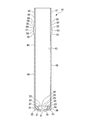
- the cylinder device 11 includes an inner tube 12 (inner cylinder) and a base shell 14 (cylinder) that is a cylinder.
- the inner tube 12 is a cylindrical member in which a working liquid is enclosed.
- the base shell 14 has a larger diameter than the inner tube 12 and is provided on the outer peripheral side of the inner tube 12.
- the base shell 14 forms a reservoir chamber 13 in which a working liquid and a working gas are enclosed with the inner tube 12.
- the base shell 14 has a bottomed cylindrical shape and is an integrally molded product made of a single metal member.
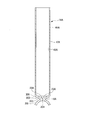
- the base shell 14 includes a side wall portion 17 and a bottom portion 18.
- the side wall portion 17 has a cylindrical shape, and the central axis is the central axis of the base shell 14.
- the end of the center axis on the bottom 18 side is referred to as a first end, and the end opposite to the bottom 18 in the axial direction is referred to as a second end.
- the bottom portion 18 closes the first end side in the axial direction of the side wall portion 17.
- the bottom 18 has a bottom main body 21, an outer bottom protrusion 22, a protrusion 23, and a recess 24.
- the bottom main body 21 is curved in a spherical shape so as to swell outward in the axial direction of the base shell 14.
- the bottom main body 21 swells so as to be positioned on the outer side in the axial direction toward the radial center of the base shell 14.
- the bottom main body 21 has a spherical R surface 31 on the outer surface and a spherical R surface 32 on the inner surface.
- the R surfaces 31 and 32 are also curved so that the radial center side of the base shell 14 is located on the outer side in the axial direction.
- the center of each spherical surface of the R surfaces 31 and 32 is arranged on the central axis of the base shell 14.
- the bottom 18 has a shape protruding to the outer surface side.
- the outer bottom projecting portion 22 projects from the outer peripheral portion of the bottom main body portion 21 to the outer side in the axial direction of the base shell 14.
- the outer bottom protrusion 22 has an annular shape.
- the outer bottom protrusion 22 has a flat surface 35 on the radially outer side of the R surface 31.
- the flat surface 35 is a flat surface extending perpendicularly to the central axis of the base shell 14, that is, the central axis of the side wall portion 17, and has an annular shape centering on the central axis of the base shell 14.
- the bottom 18 has an outer peripheral surface 36 formed of a cylindrical surface across the bottom main body 21 and the outer bottom protrusion 22.
- the outer peripheral surface 36 is a cylindrical surface centered on the central axis of the base shell 14.
- the outer surface in the axial direction of the bottom 18 has an R surface 31 on the center side and a flat surface 35 on the outer peripheral side.
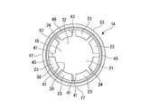
- the convex portion 23 is provided on the inner surface side of the bottom portion 18.
- the convex portion 23 is formed at a boundary position between the bottom main body portion 21 and the side wall portion 17 inside the base shell 14.
- the convex portion 23 projects from the bottom main body portion 21 in the axial direction of the base shell 14, and projects from the side wall portion 17 inward in the radial direction of the base shell 14. Therefore, the convex portion 23 is provided on the inner surface side of the bottom portion 18 and is provided on the inner peripheral surface side of the side wall portion 17.
- the convex portion 23 has an elevation surface portion 39 and an inclined surface portion 40.
- the upright portion 39 is formed such that the tip end surface 38 on the protruding side of the convex portion 23 is at the end of the base shell 14 on the center axis side and the bottom main body portion 21 side, and is along the center axis of the base shell 14. .
- the inclined surface portion 40 is formed on the opposite side to the bottom main body portion 21 in the elevation surface portion 39 so as to be inclined so as to approach the side wall portion 17 as the distance from the elevation surface portion 39 increases.
- the side surfaces 41 on both sides in the circumferential direction of the base shell 14 are parallel to each other along the axial direction and the radial direction of the base shell 14.
- a plurality of protrusions 23 are formed at equal intervals in the circumferential direction of the base shell 14, specifically, eight places.
- a recess between the protrusions 23 adjacent to each other in the circumferential direction of the base shell 14 is recessed in the axial direction of the base shell 14 and recessed outward in the radial direction of the base shell 14 from the tip surface 38 of the protrusion 23. 24. Therefore, the concave portion 24 is also provided on the inner surface side of the bottom portion 18 and is provided on the inner peripheral surface side of the side wall portion 17. A plurality of the recesses 24 are also formed at equal intervals in the circumferential direction of the base shell 14, specifically, eight places.
- the concave portion 24 is formed by a pair of opposing side surface portions 41 of adjacent convex portions 23, a portion of the R surface 32 of the bottom main body portion 21, and a portion of the inner peripheral surface 43 of the side wall portion 17.
- the width of the concave portion 24 in the circumferential direction of the base shell 14 is narrower than that of the convex portion 23.
- the side wall 17 has a cylindrical inner peripheral surface 43, a side wall main body 46, and an annular side wall protrusion 47.
- the side wall main body 46 is cylindrical and is a cylindrical body having first and second outer peripheral surfaces 44 and 45 having the same diameter.
- the side wall protrusion 47 is an annular portion that protrudes radially outward from the side wall main body 46.
- the side wall main body 46 has a bottom side small diameter portion 48 on the bottom 18 side of the side wall protrusion 47 and an opening side small diameter portion 49 on the side opposite to the bottom 18 from the side wall protrusion 47, that is, the opening side. Yes.
- the first outer peripheral surface 44 is an outer peripheral surface of the bottom side small diameter portion 48
- the second outer peripheral surface 45 is an outer peripheral surface of the opening side small diameter portion 49.
- the first and second outer peripheral surfaces 44 and 45 constitute the same cylindrical surface as the outer peripheral surface 36 of the bottom portion 18.
- the side wall protruding portion 47 includes a first taper portion 51, a large diameter portion 53, a second taper portion 55, a medium diameter portion 57, and a third taper portion 59 in order from the bottom 18 side in the axial direction. is doing.
- the 1st taper part 51 has the taper surface 52 which becomes large diameter, so that it leaves
- the large diameter portion 53 has a large diameter surface 54 having a constant diameter larger than the first and second outer peripheral surfaces 44 and 45 on the outer peripheral side.
- the 2nd taper part 55 has the taper surface 56 which becomes a small diameter, so that it leaves
- the medium diameter portion 57 has a medium diameter surface 58 having a constant diameter larger than the first and second outer peripheral surfaces 44 and 45 and smaller than the large diameter surface 54 on the outer peripheral side.
- the third taper portion 59 has a taper surface 60 having a smaller diameter on the outer peripheral side as the distance from the medium diameter surface 58 in the axial direction increases.
- the side wall protruding portion 47 and the side wall main body portion 46 constitute an attachment portion 64 to which a spring seat 65 indicated by a two-dot chain line in FIG. 1 is attached.
- the side wall protrusion 47 reinforces the attachment part 64 to which the spring seat 65 is attached by increasing the thickness of the side wall body part 46.
- the spring seat 65 is attached to the side wall protruding portion 47 by press-fitting a cylindrical fitting portion 66 of the spring seat 65 into the middle diameter portion 57.
- the side wall portion 17 is inserted into the cylindrical fitting portion 68 of the in-vehicle bracket 67 on the bottom portion 18 side.
- the outer bottom protruding portion 22 of the bottom portion 18 is located on the inner peripheral surface of the fitting portion 68 at the position of the flat surface 35. Welded to.
- the welding part 69 which connects the outer bottom protrusion part 22 and the fitting part 68 is formed.
- the welding position near the boundary between the bottom main body portion 21 and the fitting portion 68 becomes a deep position in the axial direction, and the welding torch is used as the base shell 14 or the bracket. 67 easily interferes with the welding position.
- the welding torch hardly interferes with the base shell 14 and the bracket 67, and the flat surface 35 and the fitting are satisfactorily fitted. It reaches the welding position near the boundary of the portion 68.
- the outer bottom protruding portion 22 is not the flat surface 35 extending perpendicularly to the central axis of the base shell 14, that is, the central axis of the side wall portion 17, the outer side in the axial direction of the bottom portion 18 is longer than the extended surface of the R surface 31. As long as the surface is located at
- the inner tube 12 has a cylindrical shape and is an integrally molded product made of a single metal member.
- a base member 70 is attached to the inner tube 12 at a first end portion on the first end side in the axial direction.
- the base member 70 has an annular shape.
- the inner tube 12 is engaged with the bottom 18 of the base shell 14 via the base member 70.
- a rod guide 71 is attached to the inner tube 12 at a second end portion on the second end side in the axial direction.
- the rod guide 71 is annular.
- the inner tube 12 is engaged with the side opposite to the bottom 18 of the side wall 17 of the base shell 14 via the rod guide 71.
- the base member 70 is placed on the bottom 18 of the base shell 14 in a state of being fitted and fixed to the inner tube 12.
- the base member 70 is placed on the R surface 32 of the bottom main body portion 21 of the bottom portion 18.
- the base member 70 is positioned in the radial direction by the plurality of convex portions 23 of the bottom portion 18 of the base shell 14. That is, the base member 70 is fitted at the position of the elevation surface portion 39 of the plurality of convex portions 23.
- the base member 70 is disposed coaxially with the base shell 14.
- the base member 70 is disposed so that one end of the inner tube 12 in the axial direction is coaxial with the base shell 14.
- the rod guide 71 is fitted to the inner tube 12 and the side wall portion 17 of the base shell 14. Accordingly, the second end portion of the inner tube 12 in the axial direction is arranged coaxially with the base shell 14 by the rod guide 71.
- a seal member 73 is disposed on the rod guide 71 at a position opposite to the bottom portion 18. The seal member 73 is annular. The seal member 73 is also fitted to the inner peripheral portion of the side wall portion 17.
- a locking portion 74 is formed on the base shell 14 on the side opposite to the bottom portion 18. The locking portion 74 is formed by bending the side opposite to the bottom 18 of the side wall portion 17 in the base shell 14 radially inward. The seal member 73 is locked to the locking portion 74 at the outer side in the axial direction.
- a piston 80 is slidably fitted in the inner tube 12.
- the piston 80 defines a first chamber 81 and a second chamber 82 in the inner tube 12.
- the first chamber 81 is provided between the piston 80 in the inner tube 12 and the rod guide 71.
- the second chamber 82 is provided between the piston 80 in the inner tube 12 and the base member 70.
- the second chamber 82 in the inner tube 12 is defined by the base member 70 and the reservoir chamber 13 formed by the base shell 14 and the inner tube 12.
- a rod 85 is connected to the piston 80 by a nut 86.
- the rod 85 passes through the rod guide 71 and the seal member 73.
- the rod 85 has a first end disposed inside the base shell 14 and the inner tube 12 and a second end disposed outside the base shell 14 and the inner tube 12.
- the rod 85 has a first end connected to the base shell 14 and the piston 80 in the inner tube 12, and a second end extended to the outside of the inner tube 12 and the base shell 14.
- the rod 85 moves in the axial direction with respect to the inner tube 12 and the base shell 14.
- the rod 85 moves integrally with the piston 80 when moving in the axial direction.
- the seal member 73 closes between the base shell 14 and the rod 85.
- the seal member 73 restricts the working liquid in the inner tube 12 and the working gas and working liquid in the reservoir chamber 13 from leaking to the outside.
- the piston 80 is formed with a first passage 91 and a second passage 92 penetrating in the axial direction.
- the first and second passages 91 and 92 can communicate the first chamber 81 and the second chamber 82.
- the piston 80 is provided with a disk valve 95 on the side opposite to the bottom 18 in the axial direction.
- the disc valve 95 has an annular shape and can close the first passage 91 by contacting the piston 80.
- the piston 80 is provided with a disk valve 96 on the bottom 18 side in the axial direction.
- the disc valve 96 has an annular shape and can close the second passage 92 by contacting the piston 80.
- the piston 80 moves in the direction of narrowing the second chamber 82. Accordingly, when the pressure in the second chamber 82 becomes higher than the pressure in the first chamber 81 by a predetermined value or more, the disc valve 95 opens the first passage 91. At this time, the disc valve 95 generates a damping force.
- the disc valve 96 opens the second passage 92. At this time, the disc valve 96 generates a damping force.
- the base member 70, the disk valve 101 disposed on the bottom 18 side in the axial direction, and the disk valve 102 disposed on the side opposite to the bottom 18 in the axial direction constitute a body valve 103.
- the base member 70 has a disk-shaped partition part 111 and a plurality of projecting parts 112.
- the partition 111 is fitted to the inner tube 12.
- the plurality of projecting portions 112 project from the circumferentially spaced positions of the partition portion 111 toward the bottom 18 side.
- the base member 70 is in contact with the R surface 32 at the plurality of protruding portions 112 and is in contact with the elevation surface portions 39 of the plurality of convex portions 23.
- a radial passage 113 is formed between the protrusion 112 and the protrusion 112 adjacent to each other in the circumferential direction. Therefore, a plurality of radial passages 113 are also formed at equally spaced positions in the circumferential direction of the partition portion 111.
- An intermediate chamber 114 is provided between the partition portion 111 and the bottom portion 18.
- the radial passage 113 becomes a flow path through which the intermediate chamber 114 and the reservoir chamber 13 are circulated.
- the phases of the concave portion 24 of the bottom portion 18 and the radial passage 113 of the base member 70 are matched in the circumferential direction of the base member 70.
- bulb 103 become a flow path which can connect the intermediate
- the number and width of the recesses 24 and the number and width of the radial passages 113 are such that any one of the recesses 24 and the radial passages 113 does not have to be positioned with respect to the bottom 18 in the circumferential direction.
- the phase is set so that it always matches (the positions in the circumferential direction overlap).
- a passage 116 and a passage 117 penetrating in the axial direction are formed in the partition portion 111.
- the passages 116 and 117 are configured to allow the second chamber 82 in the inner tube 12 to communicate with the intermediate chamber 114 and the reservoir chamber 13 through the radial passage 113.
- the inside of the concave portion 24 of the bottom portion 18 and the space between the concave portion 24 and the body valve 103 become a flow path capable of communicating the second chamber 82 and the reservoir chamber 13.
- the disc valve 101 has an annular shape and can close the passage 116 by contacting the base member 70.
- the disk valve 102 has an annular shape and can close the passage 117 by contacting the base member 70.
- the body valve 103 is disposed between the bottom 18 in the base shell 14 and the inner tube 12.
- the base member 70 partitions the second chamber 82 and the reservoir chamber 13 in the inner tube 12. Inside the cylinder device 11, an inner tube 12, a reservoir chamber 13, and a body valve 103 are provided.
- the disk valve 101 is a check valve.
- the disk valve 101 allows the flow of the working liquid from the second chamber 82 to the reservoir chamber 13 side via the passage 116 and restricts the flow of the working liquid through the passage 116 in the opposite direction.
- the disc valve 101 opens the passage 116 when the rod 85 moves to the contraction side and the pressure in the second chamber 82 becomes higher than the pressure in the reservoir chamber 13 by a predetermined value or more.
- the disc valve 101 is a damping valve that generates a damping force at that time.
- the disk valve 102 is a check valve.
- the disc valve 102 allows the flow of the working liquid from the reservoir chamber 13 to the second chamber 82 side through the passage 117 and restricts the flow of the working liquid through the passage 117 in the opposite direction.
- the disc valve 102 opens the passage 117 when the rod 85 moves to the extension side, the piston 80 moves to the first chamber 81 side, and the pressure in the second chamber 82 falls below the pressure in the reservoir chamber 13.
- the disk valve 102 is a suction valve that allows the working liquid to flow from the reservoir chamber 13 into the second chamber 82 without substantially generating a damping force.
- the rod 85 is connected to the vehicle body side of the vehicle, and the base shell 14 is connected to the vehicle wheel side via the bracket 67.
- the cylinder device 11 generates a damping force with respect to the movement of the wheel relative to the vehicle body.
- the rod 85 and the base shell 14 receive an impact force from the outside.
- the method for manufacturing the cylinder device according to the first embodiment is a part of the method for manufacturing the cylinder device 11.
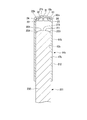
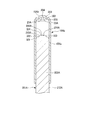
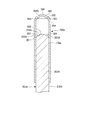
- the cylinder device manufacturing method according to the first embodiment is a tube forming method for manufacturing the bottomed cylindrical base shell 14 shown in FIGS. 2 and 3 before the engaging portion 74 is formed at the open end. The process shown in FIG. 4 is included.
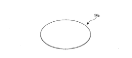
- a shearing process for forming the blank material 14a shown in FIG. 5 from a flat plate having a predetermined thickness is performed (step S1 shown in FIG. 4).
- the blank material 14a has a constant thickness and a flat plate shape with a predetermined size.
- the shearing process S1 is cold working.
- a drawing process is performed (step S2 shown in FIG. 4).
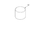
- the flat blank 14a shown in FIG. 5 is deep-drawn to form a bottomed cylindrical intermediate formed body 14a ′ shown in FIG.
- Deep drawing is a kind of drawing and is performed by a press molding machine (not shown) having a die composed of a die and a punch.
- the drawing process S2 is also cold working.
- the deep drawing is performed in a plurality of times to gradually increase the depth of the intermediate formed body, and gradually increase the length of the intermediate formed body.
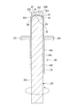
- the intermediate formed body 14b after the drawing step S2 has a bottom having a cylindrical side wall portion 17b and a bottom portion 18b that closes the first end side in the axial direction of the side wall portion 17b by the top surface processing in the drawing step S2. It becomes an attached cylinder.
- the bottom portion 18b is formed with a bottom main body portion 21b, an outer bottom protruding portion 22b, a convex portion 23, and a concave portion 24 by the top surface processing in the drawing step S2.
- the bottom main body portion 21 b has R surfaces 31 and 32.
- the R surfaces 31 and 32 are formed by a mold in the drawing step S2.
- the outer bottom protrusion 22 b has a flat surface 35.
- the flat surface 35 is formed by a mold in the drawing step S2.
- the convex part 23 which has the front end surface 38, the upright surface part 39, the inclined surface part 40, and the side surface part 41 shown in FIGS. 1 and 3 is formed by a mold in the drawing step S2.
- the recess 24 having the side surface portion 41, a part of the R surface 32 of the bottom main body portion 21, and a part of the inner peripheral surface 43 of the side wall portion 17 is also formed by a mold in the drawing step S2. That is, the inner surface side of the bottom portion 18b shown in FIG. 7 has the same shape as the inner surface side of the bottom portion 18 shown in FIGS. As shown in FIG. 7, a tapered outer peripheral surface 36b is formed on the outer peripheral side of the bottom portion 18b so as to extend toward the side wall portion 17b. The outer peripheral surface 36b has a larger diameter as it moves away from the flat surface 35 in the axial direction.
- the drawing step S2 which is an intermediate formed body processing step includes a bottom 18b and a cylindrical side wall portion 17b from the blank material 14a, and a bottomed portion having a concave portion 24 and a convex portion 23 on the inner surface side of the bottom portion 18b.
- a cylindrical intermediate formed body 14b is formed.
- the bottom portion processing step which is the deep drawing processing that is performed first among the multiple deep drawing steps in the drawing step S2.
- the outer peripheral surface 36b, and the portion of the R surface 32 excluding the recess 24 are formed. That is, the bottom surface processing step forms the R surface 31 on the center side and the flat surface 35 on the outer peripheral side on the outer surface of the bottom portion 18b.
- the convex part 23 and the concave part 24 are formed by the uneven
- the reason for performing the unevenness processing step after the bottom processing step is as follows.
- the convex portion 23 and the concave portion 24 are formed first, and then the flat surface 35 of the outer bottom protruding portion 22 is formed, the convex portion 23 and the concave portion 24 may be crushed when the flat surface 35 of the outer bottom protruding portion 22 is formed. There is sex. In order to avoid this, it is preferable to form the convex portion 23 and the concave portion 24 after the plane 35. Further, in the drawing step S2, the tapered outer peripheral surface 36b is formed outside the flat surface 35, so that the metal flow during press working is improved, which is preferable in terms of forming. The tapered outer peripheral surface 36b disappears by a subsequent spinning process.
- the intermediate molded body 14b is formed with a cylindrical side wall portion 17b continuous with the bottom portion 18b.
- the side wall portion 17b is shorter in length and thicker than the side wall portion 17 shown in FIG. 2 after the subsequent spinning process. For this reason, as shown in FIG. 7, the intermediate molded body 14b is relatively short.
- the side wall portion 17b of the intermediate molded body 14b has an inner peripheral surface 43b, an outer peripheral surface 44b, and an outer peripheral surface 36b formed of a tapered surface.
- the inner peripheral surface 43 b is a cylindrical surface having substantially the same diameter as the inner peripheral surface 43 of the side wall portion 17.
- the outer peripheral surface 44 b is a cylindrical surface having a larger diameter than the first and second outer peripheral surfaces 44 and 45 of the side wall portion 17.
- the intermediate formed body 14b is formed from the blank material 14a by a deep drawing process, which is a kind of drawing process, is shown as the intermediate formed body processing step.
- the intermediate formed body 14b may be formed from a solid low carbon steel rod having no hole on the inner peripheral side by using forging.
- the side wall portion 17b of the intermediate molded body 14b may be formed by using a spinning process which is a kind of drawing process. Moreover, you may combine these methods suitably.
- the intermediate molded body 14b is provided with a thickness (for example, 2.6 to 5.0 mm) on the side wall portion 17b.
- the blank material 14a is drawn into the gap (clearance) between the punch and the die while applying pressure to the blank material 14a with a wrinkle suppressing plate to obtain a bottomed cylindrical shape.
- the side wall 17b is pulled thin by the punch tip and the wrinkle restraining plate. For this reason, you may give the blank material 14a the thickness (for example, 5.0 mm or more) which anticipated the plate
- the short intermediate molded body 14b may be formed into a bottomed cylindrical shape by expanding the clearance of the mold and giving a simple bending deformation to the blank material.
- a spinning process is performed (step S3 shown in FIG. 4).
- the side wall portion 17b of the intermediate molded body 14b is extended in the axial direction by a spinning process performed by a spinning machine partially shown in FIGS.
- the spinning process S3 is also a cold process.
- the spinning process is a rotary process.
- the rotational processing includes screw rolling processing, gear rolling processing, profile rolling processing, cross rolling processing, helical rolling processing, disc rolling processing, rotary forging processing, rotary aging processing, and spinning processing.
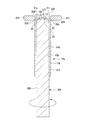
- the spinning machine has a cylindrical mandrel 201 as shown in FIG.
- the mandrel 201 has an outer surface shape that is the same shape as the inner surface shape of the intermediate molded body 14b on the tip side, and is longer in the axial direction than the intermediate molded body 14b.
- the mandrel 201 has a main body shaft portion 202, an engaging convex portion 203, and an engaging concave portion 204.
- the main body shaft portion 202 has a cylindrical shape, and the center axis thereof becomes the center axis of the mandrel 201.
- the main body shaft portion 202 is curved in a spherical shape so that the main body tip portion 205 swells outward in the axial direction of the mandrel 201.
- the main body distal end portion 205 swells so as to be positioned on the outer side in the axial direction toward the radial center side of the mandrel 201.
- the main body distal end portion 205 is an R surface 211 whose outer surface is spherical.
- the R surface 211 is also curved so that the radially central side of the mandrel 201 is positioned on the outer side in the axial direction.
- the center of the spherical surface of the R surface 211 is disposed on the central axis of the mandrel 201.
- the main body shaft portion 202 has an outer peripheral surface 212 formed of a cylindrical surface.
- the outer peripheral surface 212 is a cylindrical surface centered on the central axis of the mandrel 201.
- the outer peripheral surface 212 is a cylinder having an outer diameter substantially the same as the inner diameter of the side wall portion 17b.
- the engaging recess 204 is provided on the outer peripheral side of the main body tip portion 205 of the main body shaft portion 202.
- the engaging recess 204 is recessed from the R surface 211 in the axial direction and the radial direction of the mandrel 201.
- a plurality of engaging recesses 204 are formed at equal intervals in the circumferential direction of the mandrel 201.
- the same number of engagement recesses 204 as the protrusions 23 of the intermediate molded body 14b are provided, and all the engagement recesses 204 can be engaged with the corresponding protrusions 23 one by one.
- an engagement projection 203 that protrudes outward in the axial direction and the radial direction of the mandrel 201 from the bottom surface of the engagement recess 204. Yes. Therefore, a plurality of engaging projections 203 are also formed at equal intervals in the circumferential direction of the mandrel 201.
- the engagement convex portion 203 is narrower in the circumferential width of the base shell 14 than the engagement concave portion 204.
- the engaging convex portion 203 is a part of the main body distal end portion 205, and the main body distal end portion 205 including the engaging convex portion 203 and the engaging concave portion 204 form the distal end portion 215 of the mandrel 201.
- the mandrel 201 having the engaging convex portion 203 and the engaging concave portion 204 at the tip end portion 215 is inserted into the inner peripheral side of the intermediate molded body 14b with the tip end portion 215 at the top.
- the phases of the engaging convex portion 203 and the concave portion 24 are matched, and the phases of the engaging concave portion 204 and the convex portion 23 are matched.
- the engaging convex portion 203 enters and engages with the concave portion 24 of the intermediate molded body 14b, and the engaging concave portion 204 engages with the convex portion 23 of the intermediate molded body 14b.
- the R surface 211 of the main body distal end portion 205 comes into contact with the R surface 32 of the bottom main body portion 21b by surface contact.
- the protrusion height of the engagement protrusion 203 is slightly smaller than the depth of the recess 24, and the protrusion The protruding height of the portion 23 may be slightly smaller than the depth of the engaging recess 204.
- the intermediate molded body 14b is prevented from rotating relative to the mandrel 201, that is, is prevented from rotating. It becomes a state.
- the bottom portion 18b is preferably thick because an axial force is applied. For this reason, it is desirable to make the bottom 18b into the final shape excluding the tapered outer peripheral surface 36b in the drawing step S2.
- the R surfaces 31, 32 of the bottom main body portion 21, the flat surface 35 of the outer bottom protrusion portion 22, the convex portion 23, and the concave portion 24 are intermediate molded bodies before the spinning process S3. It forms in drawing process S2 which is a process process.
- the spinning machine has a center jig 200 shown in FIG. 8 and a plurality of rollers 221.
- the center jig 200 sandwiches the bottom 18b of the intermediate molded body 14b with the mandrel 201 inserted thereinto between the mandrel 201 and the center jig 200. In this state, the center jig 200 rotates integrally with the mandrel 201 around the central axis of the mandrel 201.
- the engaging convex portion 203 is engaged with the concave portion 24 and the engaging concave portion 204 is engaged with the convex portion 23 to prevent the intermediate molded body 14b from rotating with respect to the mandrel 201.
- the center jig 200 and the mandrel 201 are rotated together with the bottom 18b of the intermediate molded body 14b being sandwiched therebetween. Then, the intermediate molded body 14b also rotates integrally with the center jig 200 and the mandrel 201.
- the outer peripheral side of the bottom 18b and the side wall 17b of the intermediate molded body 14b is rotated by the center jig 200 and the mandrel 201.
- the outer peripheral side of the bottom 18b and the side wall 17b of the intermediate molded body 14b that is rotated from the end of the bottom 18b opposite to the side wall 17b.
- the spinning process is a process of extending the entire length of the intermediate molded body 14b by thinning the side wall portion 17b of the intermediate molded body 14b to an appropriate thickness by plastic deformation.
- the plurality of rollers 221 are simultaneously moved in the axial direction and the radial direction of the intermediate molded body 14b with the positions in the axial direction aligned with the intermediate molded body 14b.
- the positions of the tapered outer peripheral surfaces 36b of the bottom 18b and the side wall 17b shown in FIG. 8 are processed into a cylindrical surface.
- the bottom 18 is formed by forming the outer peripheral surface 36 having a constant diameter shown in FIG.
- the cylindrical outer peripheral surface 44b of the side wall portion 17b is processed into a small-diameter cylindrical surface, and the first outer peripheral surface 44 having a constant diameter shown in FIG.
- the bottom side small diameter portion 48 having the following is formed.
- the plurality of rollers 221 are moved in the axial direction while escaping radially outward to form the first tapered portion 51 having the tapered surface 52 that gradually increases in diameter.
- the large-diameter portion 53 having the large-diameter surface 54 having a constant diameter is formed by moving the plurality of rollers 221 in the axial direction.
- a second tapered portion 55 having a tapered surface 56 that gradually decreases in diameter is formed by moving the rollers 221 in the axial direction while moving the rollers 221 inward in the radial direction.
- a plurality of rollers 221 are moved in the axial direction to form a medium diameter portion 57 having a medium diameter surface 58 with a constant diameter.
- a third tapered portion 59 having a tapered surface 60 that gradually decreases in diameter is formed by moving the plurality of rollers 221 in the axial direction while moving the rollers 221 inward in the radial direction.
- the opening-side small-diameter portion 49 having the second outer peripheral surface 45 having a constant diameter is formed.
- the bottom side small diameter part 48, the first taper part 51, the large diameter part 53, the second taper part 55, the medium diameter part 57, the third taper part 59 and the opening side small diameter part 49 are all formed by spinning.
- the side wall portion 17 is plastically deformed by spinning over the entire length to form the side wall main body portion 46 and the side wall protruding portion 47.
- the attaching part 64 which was expanded in diameter by conventional bulge processing can be simultaneously formed by spinning processing. Therefore, productivity can be improved.
- the side wall portion 17b of the intermediate molded body 14b shown in FIG. 8 before the spinning process S3 is extended in the axial direction by the spinning process, as shown in FIGS.
- a small diameter portion 48, a first taper portion 51, a large diameter portion 53, a second taper portion 55, a medium diameter portion 57, a third taper portion 59, and an opening side small diameter portion 49 are formed.
- the outer diameter of the large diameter surface 54 of the large diameter portion 53 becomes the maximum outer diameter in the base shell 14 and the side wall portion 17.
- the length of the side wall portion 17 after the spinning process step S ⁇ b> 3 is longer than the length of the side wall protruding portion 47, including the bottom side small diameter portion 48 and the opening side small diameter portion 49.
- the entire side wall portion 17b of the intermediate formed body 14b shown in FIG. In other words, in the base shell 14 shown in FIG. 2, the entire side wall portion 17 is processed to have an outer diameter that is equal to or smaller than the large-diameter surface 54.
- the bottom part 18b formed by the top surface process in the drawing process S2 is not deformed except for the outer peripheral part.
- the end of the side wall main body 46 on the side opposite to the bottom 18 after the spinning process S3 is a portion where a locking portion 74 (see FIG. 1) is formed later.
- the base shell 14 shown in FIGS. 2 and 3 is obtained.
- the base shell 14 has a side wall portion 17 having a wall thickness less than that of the side wall portion 17b and long in the axial direction.
- the spinning process is a rotating process of a plate material or a pipe material. Spinning processes include drawing-spinning-conventional spinning, shear spinning, and rotary spinning (tube spinning, flow forming).
- the spinning processing step S3 of the first embodiment is a rotary ironing (flow forming) step, and the side wall portion 17b is plastically deformed and thinned to extend in the axial direction to form the side wall portion 17.
- parallel swaging may be applied in addition to the above-described rotary ironing.
- Parallel swaging is a method used for drawing the end of a tube.
- the end of the blank tube is ironed between the mandrel and the die. For this reason, it is difficult for the parallel swaging process to form the tube wall in a plurality of steps.
- parallel swaging can reduce the wall thickness as it moves in the direction of movement.
- FIG. 2 it is difficult to perform parallel swaging so as to increase the thickness in the processing movement direction.
- the mandrel 201 into which the raw tube is inserted is rotated, and the tube wall is squeezed by a plurality of rollers 221 to be extended in the axial direction.
- the clearance with the mandrel 201 is numerically controlled so that the plurality of rollers 221 are simultaneously moved in the axial direction and the radial direction of the pipe.
- the base shell 14 having a plurality of steps on the tube wall can be formed.
- the tube has been partially bulged. If the pipe wall can be formed into a stepped shape in the spinning process S3, a process of partially bulging such a pipe becomes unnecessary. Thereby, manufacturing cost can be reduced.
- the intermediate molded body 14b is work-hardened in the drawing process S2 described above.
- the processing conditions of the spinning processing step S3 are optimized to suppress the occurrence of peeling of the surface layer and the deterioration of the surface properties due to a decrease in the ductility of the intermediate molded body 14b.
- conditions that can improve the machining accuracy and surface properties and shorten the cycle time are selected. Factors that determine these conditions include factors such as the number of rotations, shape, and feed speed of the roller 221, processing method (front, back, multi-pass), and lubrication / coolant.
- the plurality of rollers 221 can be separated from the intermediate molded body 14b in the radial direction at the position of the large-diameter portion 53.
- the large-diameter portion 53 is not formed by the spinning process, and the large-diameter portion 53 remains in the state after the drawing process S2 before the spinning process S3.
- the large diameter portion 53 of the side wall protrusion 47 is not plastically deformed by spinning.
- the bottom side small diameter portion 48, the first taper portion 51, the large diameter portion 53, the second taper portion 55, the medium diameter portion 57, the third taper portion 59, and the opening side small diameter portion 49 for the side wall portion 17, the bottom side small diameter portion 48, the first taper portion 51, the large diameter portion 53, the second taper portion 55, the medium diameter portion 57, the third taper portion 59, and the opening side small diameter portion 49.
- the bottomed cylindrical base shell 14 is manufactured while thinly extending the portion of the side wall portion 17 other than the large-diameter portion 53 by spinning. Also at this time, the thickness of the side wall portion 17 is not increased by moving the material from other parts by spinning. Thereby, the thickness of the position of the large diameter part 53 after spinning process S3 becomes substantially equal to the thickness of the side wall part 17b of the intermediate molded body 14b shown in FIG. 7 before the spinning process S3.
- the intermediate molded body 14b has an outer diameter equal to or smaller than the outer diameter of the large diameter portion 53.
- the base shell 14 after the spinning step S3 has a bottom side small diameter part 48, a first taper part 51, a second taper part 55, a medium diameter part 57, and a third taper rather than the length of the large diameter part 53.
- the combined length of the portion 59 and the opening-side small diameter portion 49 is longer.
- a cleaning process for cleaning the base shell 14 is performed (step S4 shown in FIG. 4).
- a sub-assembly process for assembling parts to be assembled to the base shell 14 is performed.
- one end of the inner tube 12 is fitted to the base member 70 of the body valve 103 shown in FIG.
- the piston 80 of the rod 85 in a state where the piston 80 is attached by the nut 86 is fitted into the inner tube 12.
- the rod guide 71 supported by the rod 85 is fitted to the other end of the inner tube 12.
- the base member 70 of the body valve 103 is inserted into a portion surrounded by the plurality of convex portions 23 of the bottom portion 18 of the base shell 14, and is placed at the position of the elevation surface portion 39 of the plurality of convex portions 23. It is fitted and placed on the R surface 32 of the bottom 18.
- the recesses 24 of the bottom 18 and the radial passage 113 of the base member 70 are in phase with each other without positioning with respect to the bottom 18.
- the space between the recess 24 and the body valve 103 and the inside of the recess 24 become a flow path capable of communicating the second chamber 82 and the reservoir chamber 13 in the inner tube 12.
- a caulking process is performed in which the locking member 74 is formed on the side wall portion 17 by caulking while the seal member 73 supported by the rod 85 is pressed against the rod guide 71.
- the cylinder device 11 is manufactured through the above steps. Thereafter, the bracket 67 is welded to the bottom 18 side, or the spring seat 65 is press-fitted into the medium diameter portion 57 and attached. The bracket 67 and the spring seat 65 may be attached after the cleaning process and before the body valve assembly process.
- Patent Document 1 described above describes a shock absorber in which a piston cylinder is integrally formed into a simple bottomed cylinder by deep drawing. Thereby, the shock absorber of patent document 1 does not require a cutting process or a welding process. However, if the cylinder is molded by deep drawing, the accuracy may be reduced. In particular, when a long cylinder is formed by deep drawing, the straightness of a mold or a press machine becomes a problem. If a long cylinder is formed by deep drawing, there may be a case where required variation in thickness and straightness cannot be ensured. In addition, production of a long cylinder by deep drawing requires a high stroke press machine. As a result, the amount of capital investment increases, and the effect of reducing welding and cost reduction of the inspection process is offset. In addition, in deep drawing, even if the product diameter is made common, dies must be prepared for each length. For this reason, cost will become still higher.
- the base shell 14 is formed including the drawing step S2 and the spinning step S3.
- a bottomed cylindrical intermediate formed body 14b having a bottom portion 18b and a side wall portion 17b is formed from the flat blank material 14a by drawing.
- the side wall 17b is formed by extending the side wall 17b of the intermediate molded body 14b in the axial direction by spinning.
- the short side wall portion 17b having a simple shape is formed while the bottom portion 18 having a complicated shape is formed, thereby obtaining the intermediate molded body 14b.
- the pressure load necessary for forming the short intermediate formed body 14b can be made relatively small. Therefore, the short intermediate formed body 14b can be processed with a short punch. For this reason, it is possible to improve the variation in thickness and straightness with a small amount of bending.
- the long side shell 14 is formed by extending the side wall portion 17b of the intermediate formed body 14b thus formed in the axial direction in the spinning process S3.
- the spinning process S3 can be performed while suppressing variations in thickness and a decrease in straightness.
- the spinning processing step S3 can be corrected while processing the thickness variation and straightness of the side wall portion 17b with high processing accuracy. For this reason, with respect to the base shell 14, it is possible to suppress a reduction in processing accuracy such as a variation in thickness and a decrease in straightness. Even if an inexpensive low carbon steel such as a hot rolled steel plate (for example, SPHE) is used as a material, it can secure the same strength as a high strength steel plate (for example, a 590 grade high strength steel plate (HITEN 590)) by work hardening. Cost can be reduced.
- SPHE hot rolled steel plate
- HITEN 590 590 grade high strength steel plate
- the base shell of the cylinder device there is a method of forming a bottom portion by closing an end portion of a cylindrical material by hot spinning as in Patent Document 2.
- hot working and welding may cause contamination and liquid leakage due to poor conditions.
- the bottom cap is pressed into the bottom, the number of parts increases.
- the manufacturing method of the cylinder device according to the first embodiment the base shell 14 can be formed by cold working and can be formed without welding. Therefore, the occurrence of contamination and the possibility of liquid leakage can be reduced. Therefore, quality can be stabilized.
- the liquid leakage inspection can be omitted, and the cost can be reduced. Since it is not the method of forming a bottom part by another part, the number of parts can be decreased.
- a short intermediate formed body 14b having a thickness of 2.6 mm, 2.9 mm, 3.2 mm, 5.0 mm, or the like is formed by the drawing step S2.
- the side wall portion 17b is thinned to, for example, 1.0 mm, 1.2 mm, 1.4 mm, 2.6 mm, 2.9 mm, 3.2 mm, etc. by the spinning processing step S3 to form the side wall main body portion 46.
- the final length of the side wall portion 17 is adjusted.
- the manufacturing method of the cylinder device according to the first embodiment is suitable for multi-product mass production.
- the base shell 14 in which the bottom portion 18 and the side wall portion 17 are integrally formed a portion that is smaller than the thickness of the bottom portion 18 is provided in the side wall portion 17.
- low carbon steel such as cold rolled steel plate (for example, SPCC, SPCD, SPCE) or hot rolled steel plate (for example, SPHC, SPHD, SPHE) is used as a material.
- a Vickers hardness (compressive strength) of 200 HV comparable to that of a 590 grade high strength steel sheet can be obtained.
- the blank 18a in the drawing step S2 which is an intermediate formed body processing step, has a bottom 18b and a cylindrical side wall 17b and is recessed on the inner surface side of the bottom 18b.
- a bottomed cylindrical intermediate formed body 14b having 24 and convex portions 23 is formed.
- the mandrel 201 is inserted into the inner peripheral side of the intermediate molded body 14b, the engaging convex portion 203 of the mandrel 201 is engaged with the concave portion 24 of the intermediate molded body 14b, and the engaging concave portion 204 is convex.
- the intermediate molded body 14b is spun on the outer peripheral side of the intermediate molded body 14b in a state in which the intermediate molded body 14b is prevented from rotating with respect to the mandrel 201 by being engaged with the portion 23, thereby extending the entire length of the intermediate molded body 14b.
- the intermediate molded body 14b can be prevented from slipping in the rotation direction with respect to the mandrel 201. Therefore, in the spinning process, it is possible to suppress a decrease in machining accuracy and a machining defect due to slip of the intermediate formed body 14b due to an excessive machining load.
- the intermediate molded body 14b can be prevented from rotating with respect to the mandrel 201, it is sufficient that at least one engaging convex portion 203 and concave portion 24 to be engaged with each other are formed. Furthermore, by providing a plurality of engaging projections 203 and a plurality of recesses 24, phase alignment for engagement becomes easy and the life of the mandrel 201 is improved. Similarly, it is sufficient that at least one engaging recess 204 and protrusion 23 that are engaged with each other are formed. Furthermore, by providing a plurality of engagement recesses 204 and a plurality of protrusions 23, phase alignment for engagement is facilitated, and the life of the mandrel 201 is improved.
- the body valve 103 when the body valve 103 is assembled to the base shell 14, the space between the recess 24 of the base shell 14 and the body valve 103 and the interior of the recess 24 are the second chamber 82 in the inner tube 12. And a flow path capable of flowing through the reservoir chamber 13. For this reason, the body valve 103 can be reduced in size by the passage area of the recess 24, and the weight can be reduced.
- an R surface 31 is formed on the center side on the outer surface of the bottom portion 18, and a flat surface 35 is formed on the outer peripheral side. Therefore, the position of the flat surface 35 can be welded at the time of welding the bracket 67 to the bottom portion 18, interference with the bracket 67 and the bottom portion 18 of the welding torch is reduced, and stable welding can be easily performed. Therefore, poor welding can be suppressed. Note that such a flat surface 35 can be formed even by the closing described in Patent Document 2.
- the thickness of the side wall portion 17 is partially changed depending on the axial position. That is, in the side wall part 17, the side wall protrusion part 47 is formed in the attachment part 64 to which the spring seat 65 which supports a spring is fixed, and it is thicker than another part. Thereby, the intensity
- the corner portion of the thick wall portion may cause stress concentration during assembly. For this reason, the corner portion of the thick portion may be reinforced by welding to disperse the stress.
- the side wall portion 17A of the base shell 14A does not have the side wall protruding portion 47 of the first embodiment, and the outer peripheral side is constituted only by the outer peripheral surface 44A having a constant diameter.
- the inner peripheral side has an inner peripheral surface 43A having a constant diameter as in the first embodiment.
- the bottom portion 18A includes a tapered cylindrical portion 301, an annular portion 302, a tapered cylindrical portion 303, and a disc portion 304, and is formed in a convex shape on the outer surface side.
- the tapered cylindrical portion 301 extends from the end edge portion in the axial direction of the side wall portion 17A.
- the tapered cylindrical portion 301 is reduced in diameter as it is away from the side wall portion 17A.
- the annular portion 302 has a flat plate shape, and extends radially inward from an end edge portion of the tapered cylindrical portion 301 on the side opposite to the side wall portion 17A.
- the tapered tubular portion 303 extends from the edge of the annular portion 302 opposite to the tapered tubular portion 301.
- the tapered cylindrical portion 303 is reduced in diameter as the distance from the annular portion 302 increases.
- the disc portion 304 has a flat plate shape, and extends radially inward from an end edge portion of the tapered tubular portion 303 on the side opposite to the annular portion 302.
- the bottom 18A is thicker than the side wall 17A in all of the tapered cylindrical portion 301, the annular portion 302, the tapered cylindrical portion 303, and the disc portion 304.
- the tapered cylindrical portions 301 and 303 are tapered with the central axis of the base shell 14A as the center.
- the annular portion 302 and the disc portion 304 extend perpendicular to the central axis of the base shell 14A.
- a plurality of, more specifically, two hemispherical convex portions 23A are formed on the inner surface side of the disc portion 304 of the bottom portion 18A so as to protrude from the disc portion 304.
- Each convex portion 23A is formed at an equal distance from the center on the diameter line passing through the center of the bottom portion 18A.
- a mounting eye 311 is fixed to the base shell 14A by welding on the outer side of the disc portion 304 of the bottom portion 18A. Although only a part of the mounting eye 311 is shown in FIG. 11, it has a cylindrical shape as a whole.
- the cylinder device manufacturing method according to the second embodiment is also a tube forming method for manufacturing the bottomed cylindrical base shell 14A shown in FIG. 11 before the locking portion is formed at the open end. The process shown in is included.
- a shearing process for forming a flat blank material is performed from a flat plate having a predetermined thickness by a shearing process that is a cold working (step SA1 shown in FIG. 12).
- a deep blanking process which is a cold work, is performed on a flat blank material to form a bottomed cylindrical intermediate molded body 14Ab shown in FIGS. (Step SA2 shown in FIG. 12).
- the deep drawing is performed in a plurality of times (for example, twice) to gradually increase the depth of the intermediate formed body, and gradually increase the length of the intermediate formed body.
- the bottom 18Ab is formed.
- a plurality of convex portions 23A are also formed on the disc portion 304 by the top surface processing in the drawing step S2.
- the intermediate molded body 14Ab is formed with a cylindrical side wall portion 17Ab continuous with the bottom portion 18Ab.
- the side wall portion 17Ab is shorter and thicker than the side wall portion 17A (shown in FIG. 11) after the subsequent spinning step SA3.
- intermediate forming is performed by forging from a solid low carbon steel rod having no holes on the inner peripheral side, in addition to forming the intermediate formed body 14Ab from the blank material by deep drawing.
- the body 14Ab may be formed.
- the intermediate molded body 14Ab may be formed by a spinning process which is a kind of drawing process. Moreover, you may combine these suitably.
- the spinning process is a process in which the side wall portion 17Ab of the intermediate molded body 14Ab is elongated in the axial direction by spinning, which is cold working by a spinning machine having a mandrel 201A shown in FIG.
- a mandrel 201A of the second embodiment has a main body shaft portion 202A having a constant diameter outer peripheral surface 212A and a tip portion 215A.
- the tip end side of the mandrel 201A has an outer surface shape that is the same shape as the inner surface shape of the intermediate molded body 14Ab. Therefore, the mandrel 201A is different from the first embodiment in the shape of the tip 215A.
- the main body shaft portion 202A has a cylindrical shape, and the central axis thereof becomes the central axis of the mandrel 201A.
- the tip portion 215A of the mandrel 201A of the second embodiment has a tapered surface portion 321, an annular planar portion 322, a tapered surface portion 323, and a circular planar portion 324.
- the tapered surface portion 321 extends so as to decrease in diameter in the axial direction as the distance from the end edge portion of the outer peripheral surface 212A increases.
- the annular flat surface portion 322 has a flat plate shape and extends radially inward from an end edge portion of the tapered surface portion 321 opposite to the outer peripheral surface 212A.
- the tapered surface portion 323 extends from the inner end edge of the annular flat surface portion 322 opposite to the tapered surface portion 321.
- the taper surface portion 323 is reduced in diameter as the distance from the annular plane portion 322 increases.
- the circular flat surface portion 324 extends radially inward from the edge of the tapered surface portion 323 opposite to the annular flat surface portion 322.
- the annular flat surface portion 322 and the circular flat surface portion 324 extend perpendicular to the central axis of the mandrel 201A.
- the tip portion 215A has a plurality of, specifically two, engagement recesses 204A that are recessed from the circular flat surface portion 324. Each engaging recess 204A is formed at an equal distance from the center on the diameter line passing through the central axis of the mandrel 201A.
- the tapered surface portion 321 contacts the tapered tubular portion 301
- the annular plane portion 322 contacts the annular portion 302
- the tapered surface portion 323 contacts the tapered tubular portion 303
- the circular planar portion 324 has a circular shape.
- the plurality of convex portions 23A are engaged with the plurality of engaging concave portions 204A by coming into contact with the plate portion 304, respectively.
- the intermediate molded body 14Ab is prevented from rotating with respect to the mandrel 201A by engaging both the convex portions 23A with the corresponding engaging concave portions 204A. Subsequently, the center jig 200A and the mandrel 201A are rotated together with the center jig 200A and the mandrel 201A sandwiching the bottom 18Ab of the intermediate molded body 14Ab. Then, the intermediate molded body 14Ab also rotates integrally with the center jig 200A and the mandrel 201A.
- the outer peripheral side of the side wall portion 17Ab of the intermediate molded body 14Ab is rotated by the center jig 200A and the mandrel 201A.
- the outer peripheral side of the side wall portion 17Ab of the intermediate molded body 14A that is being rotated is arranged on the outer side of the side wall portion 17Ab from the end of the bottom portion 18Ab opposite to the side wall portion 17Ab. Is pressed radially inward to the end opposite to the bottom 18Ab and pressed against the mandrel 201A, so that the outer peripheral side of the side wall 17Ab of the intermediate molded body 14Ab is plastically deformed and thinned to an appropriate thickness. Spinning process is performed to extend the overall length.
- the plurality of rollers 221 move in the axial direction of the intermediate molded body 14Ab with the axial positions thereof aligned with respect to the intermediate molded body 14Ab.
- the base shell 14A shown in FIG. 11 is obtained.
- the base shell 14A has a side wall portion 17A that is thinner than the side wall portion 17Ab, is longer in the axial direction, and has a constant outer diameter.
- the side shell 17A of the base shell 14A is rotated and ironed by the plurality of rollers 221 so as to have a constant outer diameter.
- step SA4 a cleaning process for cleaning the base shell 14A is performed (step SA4 shown in FIG. 12). Thereafter, an eye welding process of welding the mounting eye 311 to the outside of the bottom portion 18A is performed (step SA5 shown in FIG. 12).
- the blank material has a bottom 18Ab and a cylindrical side wall 17Ab on the inner surface side of the bottom 18Ab.
- a bottomed cylindrical intermediate formed body 14Ab having a convex portion 23A is formed.
- the mandrel 201A is inserted into the inner peripheral side of the intermediate molded body 14Ab, the engaging recess 204A of the mandrel 201A is engaged with the convex part 23A, and the intermediate molded body 14Ab is rotated with respect to the mandrel 201A.
- the outer peripheral side of the intermediate molded body 14Ab is spun and the entire length of the intermediate molded body 14Ab is extended.
- the intermediate molded body 14Ab is prevented from slipping in the rotation direction with respect to the mandrel 201A. Therefore, in the spinning process, it is possible to suppress a processing failure caused by the slip of the intermediate molded body 14Ab due to an excessive processing load.
- the number of the engaging recesses 204A of the mandrel 201A and the protrusions 23A of the intermediate molded body 14Ab may be formed at least one at a time.
- a recess may be formed on the bottom 18Ab instead of the protrusion 23A.
- a plurality of concave portions are formed on the inner surface side of the annular portion 302 of the bottom portion 18Ab.
- four concave portions 24A recessed in a hemispherical shape are formed at equal intervals in the circumferential direction at positions equidistant from the center of the bottom portion 18Ab.
- a plurality of concave portions 24 ⁇ / b> A are also formed in the annular portion 302 during the processing of the top surface.
- a spinning process is performed in which the side wall portion 17Ab of the intermediate molded body 14Ab is extended in the axial direction by a spinning process which is a cold process by a spinning machine (step SA3 shown in FIG. 12).
- the mandrel 201A has a plurality of engaging protrusions, specifically, four engaging protrusions 203A, at the front end portion 215A protruding from the annular flat surface portion 322.
- These engagement convex portions 203A are formed at equal intervals in the circumferential direction at positions equidistant from the central axis of the mandrel 201A.
- the tapered surface portion 321 contacts the tapered tubular portion 301
- the annular plane portion 322 contacts the annular portion 302
- the tapered surface portion 323 contacts the tapered tubular portion 303
- the circular planar portion 324 has a circular shape.
- the plurality of engaging projections 203A are engaged with the plurality of recesses 24A, respectively, in contact with the plate portion 304.
- the spinning step SA3 is performed in a state where the intermediate molded body 14Ab is prevented from rotating with respect to the mandrel 201A by engaging the plurality of concave portions 24A with the plurality of engaging convex portions 203A.
- the mandrel 201A is inserted into the inner peripheral side of the intermediate molded body 14Ab, and the engagement convex portion 203A of the mandrel 201A is engaged with the concave portion 24A of the intermediate molded body 14Ab.
- Spinning is performed on the outer peripheral side of the intermediate molded body 14Ab in a state where 14Ab is prevented from rotating with respect to the mandrel 201A, thereby extending the entire length of the intermediate molded body 14Ab. Since the spinning process is performed while the intermediate molded body 14Ab is prevented from rotating with respect to the mandrel 201A, the intermediate molded body 14Ab can be prevented from slipping in the rotation direction with respect to the mandrel 201A.
- the number of the engaging convex portions 203A of the mandrel 201A and the concave portions 24A of the intermediate molded body 14b may be formed at least one at a time.
- the above cylinder device 11 can be applied to various automobiles, robots, press machines, transporters, upper and lower parts of chairs, door opening and closing parts, and the like.
- the first aspect of the cylinder device manufacturing method includes a bottomed cylindrical cylinder, one end connected to a piston in the cylinder and the other end arranged outside the cylinder, and moves in the axial direction with respect to the cylinder. And a cylinder device having a bottomed cylindrical shape having a bottom portion and a cylindrical side wall portion from a blank material and having a concave portion or a convex portion on the inner surface side of the bottom portion.
- the spinning process is performed in a state where the intermediate molded body is prevented from rotating with respect to the mandrel, the intermediate molded body is prevented from sliding in the rotation direction with respect to the mandrel. Accordingly, it is possible to suppress a reduction in processing accuracy and a processing failure due to slip of the intermediate molded body in the spinning process.
- the cylinder device includes an inner cylinder, a reservoir chamber formed by the cylinder and the inner cylinder, a bottom portion of the cylinder, and the inner cylinder. And a body valve that divides the chamber in the inner cylinder and the reservoir chamber from each other, and forms the recess in the intermediate molded body processing step. There is further included a body valve assembling step for assembling the body valve to the cylinder so that a space is formed between the chamber in the inner cylinder and the reservoir chamber.
- the inside of the recess and the space between the recess of the cylinder and the body valve serve as a flow path that can flow between the chamber in the inner cylinder and the reservoir chamber. For this reason, the body valve can be reduced in size by the flow path area of the recess, and the weight can be reduced.
- the intermediate molded body processing step includes a bottom processing step of forming an R surface on the center side and a flat surface on the outer peripheral side on the outer surface of the bottom portion. Including.
- the bottom processing step in order to form a flat surface on the outer peripheral side of the outer surface of the bottom portion, for example, when welding the bracket to the bottom portion, by welding the position of the flat surface, to the bracket and the bottom portion of the welding torch Interference is reduced and stable welding can be performed easily.
- shock absorber it is possible to provide a method of manufacturing a cylinder device that can suppress a decrease in processing accuracy.
- Cylinder device 12 Inner tube (inner cylinder) 13 Reservoir chamber 14 Base shell (cylinder) 14a Blank material 14b, 14Ab Intermediate molded body 17b, 17Ab Side wall part 18b, 18Ab Bottom part 23, 23A Convex part 24, 24A Concave part 31 R surface (outer surface) 35 Plane 80 Piston 82 Second chamber (chamber in the inner cylinder) 85 Rod 103 Body valve 201, 201A Mandrel 203, 203A Engaging projection 204, 204A Engaging recess
Landscapes
- Engineering & Computer Science (AREA)
- Mechanical Engineering (AREA)
- General Engineering & Computer Science (AREA)
- Fluid-Damping Devices (AREA)
- Shaping Metal By Deep-Drawing, Or The Like (AREA)
Abstract
本シリンダ装置の製造方法は、ブランク材から底部と筒状の側壁部とを有し前記底部の内面側に凹部または凸部を有する有底筒状の中間成形体を形成する中間成形体加工工程と、前記中間成形体の前記凹部または前記凸部に係合可能な係合凸部または係合凹部を有するマンドレルを前記中間成形体の内周側に挿入し、前記凹部または前記凸部に前記係合凸部または前記係合凹部を係合させて前記中間成形体を前記マンドレルに対し回り止めした状態で前記中間成形体の外周側をスピニング加工して前記中間成形体の全長を伸長させるスピニング加工工程と、を含んで有底筒状の前記シリンダを形成することを特徴とする。
Description
本発明は、シリンダ装置の製造方法に関する。本願は、2016年9月27日に、日本に出願された特願2016-188039号に基づき優先権を主張し、その内容をここに援用する。
シリンダを深絞り体で形成したショックアブソーバがある(例えば、特許文献1参照)。また、シリンダの底部をクロージング加工によって形成する方法がある(例えば、特許文献2参照)。また、シリンダにキャップを溶接して底部を形成した複筒型緩衝器がある(例えば、特許文献3参照)。
シリンダを深絞りで成形すると精度が低下する可能性がある。
したがって、本発明は、加工精度低下を抑制することができるシリンダ装置の製造方法の提供を目的とする。
本発明の第1の態様によれば、シリンダ装置の製造方法は、シリンダと、第一端側が前記シリンダ内のピストンに接続され第二端側が前記シリンダの外部に配置されて前記シリンダに対して軸方向に移動するロッドと、を有するシリンダ装置の製造方法であって、ブランク材から底部と筒状の側壁部とを有し前記底部の内面側に凹部または凸部を有する有底筒状の中間成形体を形成する中間成形体加工工程と、前記中間成形体の前記凹部または前記凸部に係合可能な係合凸部または係合凹部を有するマンドレルを前記中間成形体の内周側に挿入し、前記凹部または前記凸部に前記係合凸部または前記係合凹部を係合させて前記中間成形体を前記マンドレルに対し回り止めした状態で前記中間成形体の外周側をスピニング加工して前記中間成形体の全長を伸長させるスピニング加工工程と、を含んで有底筒状の前記シリンダを形成することを特徴とする。
本発明の第2の態様によれば、第1の態様に係るシリンダ装置の製造方法は、前記スピニング加工工程では、前記中間成形体の外周の大半をスピニング加工により形成してもよい。
本発明の第3の態様によれば、第1または第2の態様に係るシリンダ装置の製造方法では、前記シリンダ装置は、内部に、内筒と、前記シリンダと前記内筒とで形成されるリザーバ室と、前記シリンダの底部と前記内筒との間に配されて前記内筒内の室と前記リザーバ室とを区画するボデーバルブと、が設けられ、前記中間成形体加工工程では前記凹部を形成し、前記凹部と前記ボデーバルブとの間が、前記内筒内の室と前記リザーバ室とを流通可能な流路となるように前記ボデーバルブを前記シリンダに組み付けるボデーバルブ組付工程をさらに含んでもよい。
本発明の第4の態様によれば、第1から第3のいずれかの態様に係るシリンダ装置の製造方法では、前記中間成形体加工工程は、前記底部の外面に、中央側にR面を、外周側に平面を形成する底部加工工程を含んでもよい。
本発明によれば、加工精度低下を抑制することができる。
[第1実施形態]
本発明に係る第1実施形態に係るシリンダ装置の製造方法を図1~図10を参照して以下に説明する。
本発明に係る第1実施形態に係るシリンダ装置の製造方法を図1~図10を参照して以下に説明する。
まず、第1実施形態に係るシリンダ装置の製造方法で製造されるシリンダ装置11を、図1を参照して説明する。図1に示すシリンダ装置11は、自動車や鉄道車両等の車両のサスペンション装置に用いられる緩衝器であり、複筒式の緩衝器である。シリンダ装置11は、インナチューブ12(内筒)と、シリンダであるベースシェル14(シリンダ)とを有している。インナチューブ12は、作動液体が封入される円筒状の部材である。ベースシェル14は、インナチューブ12よりも大径であり、インナチューブ12の外周側に設けられている。ベースシェル14は、インナチューブ12との間に作動液体および作動気体が封入されるリザーバ室13を形成している。
図1および図2に示すように、ベースシェル14は、有底筒形状を有し、金属製の一部材からなる一体成形品である。ベースシェル14は、側壁部17と底部18とからなっている。側壁部17は円筒形状を有し、中心軸線がベースシェル14の中心軸線となる。以後の説明において、中心軸線の底部18側の端部側を第一端側と称し、底部18とは軸方向反対側の端部側を第二端側と称する。底部18は側壁部17の軸方向の第一端側を閉塞している。底部18は、底本体部21と、外底突出部22と、凸部23と、凹部24とを有している。
底本体部21は、ベースシェル14における軸方向の外側に膨らむように球面状に湾曲している。底本体部21は、ベースシェル14における径方向の中央側ほど軸方向の外側に位置するように膨らんでいる。底本体部21は、外面が球面状のR面31となっており、内面も球面状のR面32となっている。各R面31,32も、ベースシェル14における径方向の中央側ほど軸方向の外側に位置するように湾曲している。各R面31,32は球面の中心がベースシェル14の中心軸線上に配置されている。底本体部21の形状によって、底部18は、外面側に突出する形状を有している。
外底突出部22は、底本体部21の外周部からベースシェル14における軸方向の外側に突出している。外底突出部22は円環状となっている。外底突出部22は、R面31の径方向外側に平面35を有している。平面35は、ベースシェル14の中心軸線、つまり側壁部17の中心軸線に直交して広がる平面であり、ベースシェル14の中心軸線を中心とする円環形状を有する。
底部18は、底本体部21と外底突出部22とにわたって、円筒面からなる外周面36を有している。外周面36は、ベースシェル14の中心軸線を中心とする円筒面となっている。底部18の軸方向の外面は、中央側にR面31を、外周側に平面35を有している。
凸部23は、底部18の内面側に設けられている。凸部23は、ベースシェル14の内側における底本体部21と側壁部17との境界位置に形成されている。凸部23は、底本体部21からベースシェル14の軸方向内側に突出し、側壁部17からベースシェル14の径方向内側に突出する。よって、凸部23は底部18の内面側に設けられており、側壁部17の内周面側に設けられている。凸部23は、図1に示すように、立面部39と、傾斜面部40とを有している。立面部39は、凸部23の突出側の先端面38がベースシェル14の中心軸線側かつ底本体部21側の端部にあってベースシェル14の中心軸線に沿うように形成されている。傾斜面部40は、立面部39における底本体部21とは反対側に、立面部39から離れるほど側壁部17に近づくように傾斜するように形成されている。凸部23は、図3に示すようにベースシェル14の周方向において両側の側面部41がベースシェル14の軸方向および径方向に沿い互いに平行となっている。凸部23は、ベースシェル14の周方向に等間隔で複数、具体的には8カ所形成されている。
ベースシェル14の周方向において隣り合う凸部23と凸部23との間が、凸部23の先端面38よりも、ベースシェル14の軸方向に凹み、ベースシェル14の径方向外側に凹む凹部24となっている。よって、凹部24も、底部18の内面側に設けられており、側壁部17の内周面側に設けられている。凹部24も、ベースシェル14の周方向に等間隔で複数、具体的には8カ所形成されている。凹部24は、隣り合う凸部23の対向する一対の側面部41と底本体部21のR面32の一部と側壁部17の内周面43の一部とで形成されている。凹部24は、凸部23よりも、ベースシェル14の円周方向の幅が狭くなっている。
図2に示すように、側壁部17は、円筒状の内周面43と、側壁本体部46と、円環状の側壁突出部47とを有している。側壁本体部46は、円筒状であり、互いに同径の第1および第2外周面44,45を有する円筒体である。側壁突出部47は、側壁本体部46から径方向外方に突出する円環状の部分である。側壁本体部46は、側壁突出部47よりも底部18側の底側小径部48と、側壁突出部47よりも底部18とは反対側、つまり開口側の開口側小径部49とを有している。第1外周面44は、底側小径部48の外周面であり、第2外周面45は、開口側小径部49の外周面である。第1および第2外周面44,45は、底部18の外周面36と同一の円筒面を構成している。側壁突出部47は、軸方向の底部18側から順に、第1テーパ部51と、大径部53と、第2テーパ部55と、中径部57と、第3テーパ部59と、を有している。
第1テーパ部51は、外周側に、第1外周面44から軸方向に離れるほど大径となるテーパ面52を有している。大径部53は、外周側に、第1および第2外周面44,45よりも大径の一定径の大径面54を有している。第2テーパ部55は、外周側に、大径面54から軸方向に離れるほど小径となるテーパ面56を有している。中径部57は、外周側に、第1および第2外周面44,45よりも大径かつ大径面54よりも小径の一定径の中径面58を有している。第3テーパ部59は、外周側に、中径面58から軸方向に離れるほど小径となるテーパ面60を有している。
側壁突出部47と側壁本体部46とは、図1に二点鎖線で示すスプリングシート65が取り付けられる取付部64を構成する。言い換えれば、側壁突出部47は側壁本体部46の肉厚を厚くすることでスプリングシート65が取り付けられる取付部64を補強する。側壁突出部47には、中径部57にスプリングシート65の円筒状の嵌合部66が圧入されることで、スプリングシート65が取り付けられる。
側壁部17は、底部18側が車載用のブラケット67の円筒状の嵌合部68に挿入され、この状態で底部18の外底突出部22が平面35の位置において嵌合部68の内周面に溶接される。これにより、外底突出部22と嵌合部68とを繋ぐ溶接部69が形成される。ここで、外底突出部22がなく底本体部21だけであると、底本体部21と嵌合部68の境界近傍の溶接位置が軸方向に奥深い位置となり、溶接トーチがベースシェル14やブラケット67に干渉しやすく、溶接位置まで届きにくい。これに対して、外底突出部22を設けて底部18の外周側に平面35を形成していることから、溶接トーチがベースシェル14やブラケット67に干渉しにくく、良好に平面35および嵌合部68の境界近傍の溶接位置に届く。ここで、外底突出部22が、ベースシェル14の中心軸線、つまり側壁部17の中心軸線に直交して広がる平面35でなくても、R面31の延長面よりも底部18の軸方向外側に位置する面であれば良い。
インナチューブ12は、円筒状であり、金属製の一部材からなる一体成形品である。インナチューブ12には、軸方向の第一端側の第一端部にベース部材70が取り付けられている。ベース部材70は円環状である。インナチューブ12は、ベース部材70を介してベースシェル14の底部18に係合している。インナチューブ12には、軸方向の第二端側の第二端部にロッドガイド71が取り付けられている。ロッドガイド71は円環状である。インナチューブ12は、ロッドガイド71を介してベースシェル14の側壁部17の底部18とは反対側に係合している。
ベース部材70は、インナチューブ12に嵌合し固定された状態でベースシェル14の底部18に載置されている。ベース部材70は、底部18の底本体部21のR面32に載置されている。ベース部材70がR面32に載置された際に、ベース部材70は、ベースシェル14の底部18の複数の凸部23によって径方向に位置決めされる。つまり、ベース部材70は、複数の凸部23の立面部39の位置に嵌合する。これにより、ベース部材70は、ベースシェル14と同軸状に配置される。その結果、ベース部材70は、インナチューブ12の軸方向の一端部をベースシェル14と同軸状に配置される。
ロッドガイド71は、インナチューブ12とベースシェル14の側壁部17とに嵌合している。これにより、ロッドガイド71により、インナチューブ12の軸方向の第二端部がベースシェル14と同軸状に配置される。ロッドガイド71には、底部18とは反対側の位置にシール部材73が配置されている。シール部材73は、円環状である。シール部材73も側壁部17の内周部に嵌合されている。ベースシェル14には、底部18とは反対側に係止部74が形成されている。係止部74は、ベースシェル14における側壁部17の底部18とは反対側が径方向内方に折り曲げられることによって形成されている。シール部材73は、軸方向の外側が係止部74に係止されている。
インナチューブ12内には、ピストン80が摺動可能に嵌装されている。ピストン80は、インナチューブ12内において第1室81と第2室82とを画成している。第1室81は、インナチューブ12内のピストン80とロッドガイド71との間に設けられている。第2室82は、インナチューブ12内のピストン80とベース部材70との間に設けられている。インナチューブ12内の第2室82は、ベース部材70によって、ベースシェル14とインナチューブ12とで形成されるリザーバ室13と画成されている。
ピストン80にはロッド85がナット86によって連結されている。ロッド85は、ロッドガイド71およびシール部材73を通っている。ロッド85は、第一端側がベースシェル14およびインナチューブ12内に配置され、第二端側がベースシェル14およびインナチューブ12の外部に配置されている。ロッド85は、第一端側がベースシェル14およびインナチューブ12内のピストン80に接続され、第二端側がインナチューブ12およびベースシェル14の外部へと延出されている。ロッド85は、インナチューブ12およびベースシェル14に対して軸方向に移動する。ロッド85は、軸方向の移動の際に、ピストン80と一体に移動する。シール部材73は、ベースシェル14とロッド85との間を閉塞している。シール部材73は、インナチューブ12内の作動液体と、リザーバ室13内の作動気体および作動液体とが外部に漏出するのを規制している。
ピストン80には、軸方向に貫通する第1通路91および第2通路92が形成されている。第1および第2通路91,92は、第1室81と第2室82とを連通可能となっている。ピストン80には、軸方向の底部18とは反対側にディスクバルブ95が設けられている。ディスクバルブ95は、円環状であり、ピストン80に当接することで第1通路91を閉塞可能である。ピストン80には、軸方向の底部18側にディスクバルブ96が設けられている。ディスクバルブ96は、円環状であり、ピストン80に当接することで第2通路92を閉塞可能である。
ロッド85がインナチューブ12およびベースシェル14内への進入量を増やす縮み側に移動すると、ピストン80が第2室82を狭める方向に移動する。これによって、第2室82の圧力が第1室81の圧力よりも所定値以上高くなると、ディスクバルブ95は、第1通路91を開く。このとき、ディスクバルブ95は、減衰力を発生させる。ロッド85がインナチューブ12およびベースシェル14からの突出量を増やす伸び側に移動すると、ピストン80が第1室81を狭める方向に移動する。これにより、第1室81の圧力が第2室82の圧力よりも所定値以上高くなると、ディスクバルブ96は、第2通路92を開く。このとき、ディスクバルブ96は、減衰力を発生させる。
ベース部材70と、軸方向の底部18側に配置されたディスクバルブ101と、軸方向の底部18とは反対側に配置されたディスクバルブ102とはボデーバルブ103を構成している。
ベース部材70は、円板状の区画部111と、複数の突出部112とを有している。区画部111はインナチューブ12に嵌合する。複数の突出部112は、区画部111の周方向の等間隔位置から底部18側に突出する。ベース部材70は、複数の突出部112において、R面32に当接し、複数の凸部23の立面部39に当接している。周方向に隣り合う突出部112と突出部112との間が径方向通路113を構成している。よって、径方向通路113も区画部111の周方向の等間隔位置に複数形成されている。区画部111と底部18との間は中間室114となっている。ここで、複数の凸部23の内側にベース部材70が嵌合しても、径方向通路113が中間室114とリザーバ室13とを流通させる流路となる。また、複数の凸部23の内側にベース部材70を嵌合させる際に、ベース部材70の周方向において、底部18の凹部24とベース部材70の径方向通路113との位相を合わせる。これにより、凹部24内と、凹部24とボデーバルブ103との間とが、中間室114とリザーバ室13とを連通可能な流路となる。ここで、凹部24の数および幅と、径方向通路113の数および幅とは、ボデーバルブ103を周方向において底部18に対し位置決めしなくても、いずれかの凹部24と径方向通路113の位相が必ず合う(周方向の位置が重なり合う)ように設定されている。
区画部111には、軸方向に貫通する通路116および通路117が形成されている。通路116,117は、径方向通路113を介してインナチューブ12内の第2室82と中間室114およびリザーバ室13とを連通可能に構成されている。その結果、底部18の凹部24内と、凹部24とボデーバルブ103との間とが、第2室82とリザーバ室13とを連通可能な流路となる。
ディスクバルブ101は、円環形状を有し、ベース部材70に当接することで通路116を閉塞可能である。ディスクバルブ102は、円環形状を有し、ベース部材70に当接することで通路117を閉塞可能である。ボデーバルブ103は、ベースシェル14内の底部18とインナチューブ12との間に配置されている。ベース部材70が、インナチューブ12内の第2室82とリザーバ室13とを区画する。シリンダ装置11の内部には、インナチューブ12とリザーバ室13とボデーバルブ103と、が設けられている。
ディスクバルブ101は、チェックバルブである。ディスクバルブ101は、通路116を介する第2室82からリザーバ室13側への作動液体の流れを許容し、これとは逆方向の通路116を介する作動液体の流れを規制する。ディスクバルブ101は、ロッド85が縮み側に移動して第2室82の圧力がリザーバ室13の圧力よりも所定値以上高くなると通路116を開く。ディスクバルブ101は、その際に減衰力を発生させる減衰バルブである。
ディスクバルブ102は、チェックバルブである。ディスクバルブ102は、通路117を介するリザーバ室13から第2室82側への作動液体の流れを許容し、これとは逆方向の通路117を介する作動液体の流れを規制する。ディスクバルブ102は、ロッド85が伸び側に移動しピストン80が第1室81側に移動して第2室82の圧力がリザーバ室13の圧力より下降すると通路117を開く。ディスクバルブ102は、その際に、実質的に減衰力を発生させずに、リザーバ室13から第2室82内に作動液体を流すサクションバルブである。
シリンダ装置11は、例えばロッド85が車両の車体側に連結され、ベースシェル14がブラケット67を介して車両の車輪側に連結される。シリンダ装置11は、車輪の車体に対する移動に対して減衰力を発生させる。シリンダ装置11は、ロッド85およびベースシェル14が外部から衝撃力を受ける。
次に、第1実施形態に係るシリンダ装置の製造方法について説明する。
第1実施形態に係るシリンダ装置の製造方法は、シリンダ装置11を製造する方法の一部である。第1実施形態に係るシリンダ装置の製造方法は、開口端に係止部74が形成される前の図2,図3に示す有底筒状のベースシェル14を製造する造管方法となっており、図4に示す工程を含んでいる。
まず、所定厚さの平板から、せん断加工により、図5に示すブランク材14aを形成するせん断加工工程を行う(図4に示すステップS1)。ブランク材14aは、一定厚さであり、所定の大きさの平板形状を有する。せん断加工工程S1は冷間加工である。
次に、絞り加工工程を行う(図4に示すステップS2)。絞り加工工程は、図5に示す平板状のブランク材14aに、深絞り加工を行って、図6に示す有底筒状の中間成形体14a’を形成し、これにさらに深絞り加工を行って、図7に示す有底筒状の中間成形体14bを形成する中間成形体加工工程である。深絞り加工は、絞り加工の一種であり、ダイとポンチとからなる金型を有する図示略のプレス成形機によって行われる。絞り加工工程S2も冷間加工である。ここで、絞り加工工程S2では複数回に分けて深絞り加工を行って徐々に中間成形体の深さを深くし、徐々に中間成形体の長さを長くする。絞り加工工程S2後の中間成形体14bは、絞り加工工程S2での天面加工により、円筒状の側壁部17bと側壁部17bの軸方向の第一端側を閉塞する底部18bとを有する底付円筒体となる。
底部18bは、絞り加工工程S2での天面加工により、底本体部21bと外底突出部22bと凸部23と凹部24とが形成される。底本体部21bは、R面31,32を有している。R面31,32は絞り加工工程S2において金型で形成される。外底突出部22bは、平面35を有している。平面35は絞り加工工程S2において金型で形成される。図1および図3に示す先端面38、立面部39、傾斜面部40および側面部41を有する凸部23は、絞り加工工程S2において金型で形成される。側面部41、底本体部21のR面32の一部および側壁部17の内周面43の一部を有する凹部24も、絞り加工工程S2において金型で形成される。つまり、図7に示す底部18bの内面側は、図1から図3に示す底部18の内面側と同形状になっている。図7に示すように、底部18bの外周側には側壁部17bにかけてテーパ状の外周面36bが形成されている。外周面36bは平面35から軸方向に離れるほど大径となっている。
このように、中間成形体加工工程である絞り加工工程S2は、ブランク材14aから底部18bと筒状の側壁部17bとを有し底部18bの内面側に凹部24および凸部23を有する有底筒状の中間成形体14bを形成する。
ここで、絞り加工工程S2において複数回の深絞り加工のうち、先に行われる深絞り加工である底部加工工程によって、底本体部21bのR面31の全部と、外底突出部22の平面35の全部と、外周面36bと、R面32の凹部24を除く部分と、を形成する。つまり、底部加工工程によって、底部18bの外面に、中央側にR面31を、外周側に平面35を形成する。底部加工工程の後に行われる深絞り加工である凹凸加工工程によって、凸部23および凹部24を形成する。上記のように、底部加工工程の後に凹凸加工工程を行う理由は以下の通りである。凸部23および凹部24を先に形成して、その後に外底突出部22の平面35を形成すると、外底突出部22の平面35を形成する際に、凸部23および凹部24が潰れる可能性がある。これを避けるために、平面35の後に凸部23および凹部24を形成した方が好ましい。また、絞り加工工程S2において、平面35の外側にテーパ状の外周面36bを形成するため、プレス加工時の金属の流れが良くなり、成形上好ましい。テーパ状の外周面36bは、後のスピニング加工により消滅する。
中間成形体14bには、底部18bと連続する筒状の側壁部17bが形成されている。側壁部17bは、後工程のスピニング加工工程後の図2に示す側壁部17よりも長さが短く全体的に肉厚が厚い。このため、図7に示すように、中間成形体14bは比較的短尺となる。中間成形体14bの側壁部17bは、内周面43bと、外周面44bと、テーパ面からなる外周面36bとを有している。内周面43bは、側壁部17の内周面43とほぼ同径の円筒面からなる。外周面44bは、側壁部17の第1および第2外周面44,45よりも大径の円筒面からなる。
第1実施形態では、中間成形体加工工程として、ブランク材14aから絞り加工の一種である深絞り加工により中間成形体14bを形成する例を示した。しかし、内周側に穴のない中実の低炭素鋼棒から鍛造加工を用いて中間成形体14bを形成しても良い。さらに、中間成形体14bの側壁部17bについては絞り加工の一種であるスピニング加工を用いて形成しても良い。また、これらの方法を適宜組み合わせても良い。
中間成形体加工工程においては、具体的に、後工程のスピニング加工工程を考慮して、中間成形体14bには側壁部17bに厚み(例えば2.6~5.0mm)を持たせる。絞り加工工程S2は、しわ抑え板でブランク材14aに圧力を加えながら、パンチとダイの隙間(クリアランス)にブランク材14aを引き込み有底円筒形状とする。パンチ先端としわ抑え板とにより側壁部17bは引っ張られて薄くなる。このため、板厚減少量を見込んだ厚み(例えば5.0mm以上)をブランク材14aに持たせても良い。金型のクリアランスを広げ、ブランク材に単純な曲げ変形を与えて、短尺の中間成形体14bを有底円筒形状としても良い。
次に、スピニング加工工程を行う(図4に示すステップS3)。スピニング加工工程S3は、図7~図10に一部を示すスピニング加工機によるスピニング加工により、中間成形体14bの側壁部17bを軸方向に伸ばす。スピニング加工工程S3も冷間加工である。スピニング加工は、回転加工である。ここで、回転加工には、ねじ転造加工、歯車転造加工、プロフィル転造加工、クロスローリング加工、ヘリカルローリング加工、ディスクローリング加工、回転鍛造加工、ロータリスエージング加工、スピニング加工がある。スピニング加工機は、図7に示すように、円柱状のマンドレル201を有している。
図7に示すように、マンドレル201は、先端側が中間成形体14bの内面形状と同形状の外面形状を有し、中間成形体14bよりも軸方向の長さが長い。マンドレル201は、本体軸部202と、係合凸部203と、係合凹部204とを有している。
本体軸部202は、円柱形状を有し、その中心軸線がマンドレル201の中心軸線となる。本体軸部202は、本体先端部205がマンドレル201における軸方向の外側に膨らむように球面状に湾曲している。本体先端部205は、マンドレル201における径方向の中央側ほど軸方向の外側に位置するように膨らんでいる。本体先端部205は、外面が球面状のR面211となっている。R面211も、マンドレル201における径方向の中央側ほど軸方向の外側に位置するように湾曲している。R面211は球面の中心がマンドレル201の中心軸線上に配置されている。本体軸部202は、円筒面からなる外周面212を有している。外周面212は、マンドレル201の中心軸線を中心とする円筒面となっている。外周面212は、側壁部17bの内径とほぼ同径の外径を有する円筒である。
係合凹部204は、本体軸部202の本体先端部205の外周側に設けられている。係合凹部204は、R面211からマンドレル201の軸方向および径方向に凹んでいる。係合凹部204は、マンドレル201の周方向に等間隔で複数形成されている。係合凹部204は、中間成形体14bの凸部23と同数設けられており、すべての係合凹部204が一つずつ対応する凸部23に係合可能に構成されている。
マンドレル201の周方向において隣り合う係合凹部204と係合凹部204との間が、係合凹部204の底面よりもマンドレル201の軸方向および径方向外側に突出する係合凸部203となっている。よって、係合凸部203も、マンドレル201の周方向に等間隔で複数形成されている。係合凸部203は、係合凹部204よりも、ベースシェル14の円周方向の幅が狭くなっている。係合凸部203は、中間成形体14bの凹部24と同数設けられており、すべての係合凸部203が一つずつ、対応する凹部24に係合可能に構成されている。係合凸部203は、本体先端部205の一部であり、係合凸部203を含む本体先端部205と係合凹部204とが、マンドレル201の先端部215となっている。
スピニング加工工程S3では、先端部215に係合凸部203および係合凹部204を有するマンドレル201を、先端部215を先頭にして中間成形体14bの内周側に挿入する。その際に、係合凸部203と凹部24との位相を合わせ、係合凹部204と凸部23との位相を合わせる。すると、マンドレル201は、係合凸部203が中間成形体14bの凹部24に入り込んで係合し、係合凹部204が中間成形体14bの凸部23を入り込ませて係合する。そして、本体先端部205のR面211が、底本体部21bのR面32に面接触で当接する。ここで、マンドレル201のR面211を底本体部21bのR面32に面接触で当接させるために、係合凸部203の突出高さを、凹部24の深さよりも若干小さくし、凸部23の突出高さを、係合凹部204の深さよりも若干小さくしても良い。係合凸部203を凹部24に係合させ、係合凹部204を凸部23に係合させることで、中間成形体14bがマンドレル201に対し相対回転が規制される状態、つまり回り止めされた状態となる。
なお、基本的に、スピニング加工工程S3では側壁部17bのみを加工するようにし、底部18bは加工しないほうが望ましい。底部18bは軸力が加わるため厚肉であることが望ましい。このため、絞り加工工程S2で底部18bをテーパ状の外周面36bを除いて最終形状にするほうが望ましい。つまり、ベースシェル14の底部18のうち、底本体部21のR面31,32と外底突出部22の平面35と凸部23と凹部24とについては、スピニング加工工程S3前の中間成形体加工工程である絞り加工工程S2で形成する。
スピニング加工機は、図8に示すセンタ治具200と、複数のローラ221とを有している。センタ治具200は、上記マンドレル201が内側に挿入された状態の中間成形体14bの底部18bを、マンドレル201とで挟持する。センタ治具200は、この状態で、マンドレル201の中心軸線を中心にマンドレル201と一体に回転する。
スピニング加工工程S3では、凹部24に係合凸部203を、凸部23に係合凹部204をそれぞれ係合させて中間成形体14bをマンドレル201に対し回り止めし、センタ治具200とマンドレル201とで中間成形体14bの底部18bを挟持した状態で、センタ治具200とマンドレル201とを一体に回転させる。すると、中間成形体14bも、センタ治具200およびマンドレル201と一体に回転する。
スピニング加工工程S3では、中間成形体14bの底部18bおよび側壁部17bの外周側がセンタ治具200とマンドレル201とで回転させられる。このとき、スピニング加工工程S3では、回転させられている中間成形体14bの底部18bおよび側壁部17bの外周側を、複数のローラ221が、底部18bにおける側壁部17bとは反対側の端部から中間成形体14bにおける底部18bとは反対側の端部まで、径方向内方に押圧してマンドレル201側に押し付けることによって、中間成形体14bの底部18bおよび側壁部17bの外周側を塑性変形させて適宜の厚さに薄肉化するスピニング加工を行う。スピニング加工は、中間成形体14bの側壁部17bを塑性変形により適宜の厚さに薄肉化することによって、中間成形体14bの全長を伸長させる加工でもある。スピニング加工の際に、複数のローラ221は、中間成形体14bに対する軸方向の位置を揃えて、中間成形体14bの軸方向と半径方向とに同時に移動する。
具体的には、複数のローラ221を底部18bから中間成形体14bの軸方向に移動させることで、図8に示す底部18bおよび側壁部17bのテーパ状の外周面36bの位置を円筒面に加工して、図9に示す一定径の外周面36を形成することで底部18を形成する。これに続いて、複数のローラ221を軸方向に移動させることで、側壁部17bの円筒状の外周面44bを小径の円筒面に加工して、図10に示す一定径の第1外周面44を有する底側小径部48を形成する。これに続いて、複数のローラ221を径方向外側に逃がしながら軸方向に移動させることで、徐々に大径となるテーパ面52を有する第1テーパ部51を形成する。これに続いて、複数のローラ221を軸方向に移動させることで一定径の大径面54を有する大径部53を形成する。これに続いて、複数のローラ221を径方向内側に移動させながら軸方向に移動させることで徐々に小径となるテーパ面56を有する第2テーパ部55を形成する。これに続いて、複数のローラ221を軸方向に移動させることで一定径の中径面58を有する中径部57を形成する。これに続いて、複数のローラ221を径方向内側に移動させながら軸方向に移動させることで徐々に小径となるテーパ面60を有する第3テーパ部59を形成する。これに続いて、複数のローラ221を軸方向に移動させることで、一定径の第2外周面45を有する開口側小径部49を形成する。
このようにして、底側小径部48、第1テーパ部51、大径部53、第2テーパ部55、中径部57、第3テーパ部59および開口側小径部49をすべてスピニング加工により形成する。言い換えれば、側壁部17を、全長にわたってスピニング加工により塑性変形させて、側壁本体部46および側壁突出部47を形成する。これにより、従来バルジ加工により拡径させていた取付部64をスピニング加工で同時に形成することができる。よって、生産性を向上させることができる。
以上により、スピニング加工工程S3では、スピニング加工工程S3前の図8に示す中間成形体14bの側壁部17bを、スピニング加工により軸方向に伸ばしつつ、図9から図10に示すように、底側小径部48、第1テーパ部51、大径部53、第2テーパ部55、中径部57、第3テーパ部59および開口側小径部49を形成する。スピニング加工工程S3では、ベースシェル14および側壁部17において、大径部53の大径面54の外径が最大外径となる。
スピニング加工工程S3後の側壁部17は、側壁部17の軸方向において、側壁突出部47の長さよりも、底側小径部48および開口側小径部49を合わせた長さの方が長くなる。スピニング加工工程S3では、図7に示す中間成形体14bの側壁部17bの全部をスピニング加工する。言い換えれば、図2に示すベースシェル14は、側壁部17の全部がスピニング加工されて大径面54以下の外径に加工されている。なお、スピニング加工工程S3は、絞り加工工程S2での天面加工により形成された底部18bを、外周部を除き変形させない。スピニング加工工程S3後の側壁本体部46における底部18とは反対側の端部が、後に係止部74(図1参照)が形成される部分となる。
以上により、図2および図3に示すベースシェル14を得る。ベースシェル14は、側壁部17bの肉厚以下の肉厚で軸方向に長い側壁部17を有している。スピニング加工は、板材または管材の回転加工である。スピニング加工には、絞りスピニング加工-へら絞り加工(conventional spinning)と、しごきスピニング加工(shear spinning)と、回転しごき加工(tube spinning,flow forming)とがある。第1実施形態のスピニング加工工程S3は、具体的には、回転しごき加工(フローフォーミング)工程であり、側壁部17bを塑性変形させて薄肉化しつつ軸方向に伸ばして側壁部17とする。
図7に示す中間成形体14bから側壁部17bを軸方向に伸ばすことで、図2に示すベースシェル14とするには、前述の回転しごき加工以外に、平行スエージ加工の適用も考えられる。平行スエージ加工は、管の端部の絞りに用いられる方法である。しかし、平行スエージ加工は、マンドレルとダイとの間で素管の端部をしごき加工する。このため、平行スエージ加工は、管壁を複数の段付きに形成することは難しい。特に、平行スエージ加工は、移動方向に移動するに従って肉厚を減じることはできる。しかし、平行スエージ加工は、図2に示すように、加工移動方向に肉厚を増やすように加工することは難しい。一方、スピニング加工は、素管を挿入したマンドレル201を回転させ、管壁を複数のローラ221によってしごくことで軸方向に延伸させる。スピニング加工では、複数のローラ221を管の軸方向と半径方向とに同時に移動させるように、マンドレル201とのクリアランスを数値制御する。これにより、管壁に複数の段部を持つベースシェル14を形成できる。管にスプリングシートの嵌合部を成形するために、従来は、管を部分的にバルジ加工することが行われていた。スピニング加工工程S3において管壁を段付き形状に形成できれば、このような管を部分的にバルジ加工する工程が不要となる。これにより、製造コストを低減できる。
具体的な方法について説明する。中間成形体14bと一体に回転するセンタ治具200およびマンドレル201の回転が、予め設定された所定の回転数(例えば100~3000rpm)に達したことを確認する。すると、複数(2つ以上)のローラ221を、数値制御で移動させて、径方向のマンドレル201との間のクリアランスを軸方向位置に応じて一定させたり、変化させたりして軸方向に移動させる。このクリアランスは、中間成形体14bの側壁部17bの肉厚よりも小さい。このため、ローラ221は、側壁部17bを、しごき加工しながら薄く軸方向に伸ばす回転しごき加工(前方回転しごき加工、後方回転しごき加工)を行う。ここで、中間成形体14bは、上記した絞り加工工程S2で加工硬化している。このため、スピニング加工工程S3の加工条件を最適化して、中間成形体14bの延性低下による表面層剥離の発生、表面性状の悪化を抑制する。スピニング加工工程S3において、加工精度と表面性状の向上とサイクルタイムの短縮が可能な条件を選定する。これらの条件を決める因子には、ローラ221の回転数・形状・送り速度、加工方法(前方、後方、多パス)、潤滑・冷却剤といった因子がある。
ここで、スピニング加工工程S3において、大径部53の位置で複数のローラ221を中間成形体14bから径方向外側に離すことも可能である。これにより、大径部53をスピニング加工で形成せずに、スピニング加工工程S3前の絞り加工工程S2後の状態のままで大径部53にする。言い換えれば、側壁突出部47の大径部53はスピニング加工により塑性変形させない。さらに言い換えれば、側壁部17について、底側小径部48、第1テーパ部51、大径部53、第2テーパ部55、中径部57、第3テーパ部59および開口側小径部49のうち、底側小径部48、第1テーパ部51、第2テーパ部55、中径部57、第3テーパ部59および開口側小径部49のみをスピニング加工で形成しても良い。その結果、側壁部17について大径部53以外の部分をスピニング加工により薄く伸ばしながら有底筒状のベースシェル14を製造する。このときも、側壁部17について、スピニング加工により他部位から材料を移動させて厚さを厚くすることはない。これにより、スピニング加工工程S3後の大径部53の位置の厚さが、スピニング加工工程S3前の図7に示す中間成形体14bの側壁部17bの厚さと略等しくなる。
つまり、スピニング加工工程S3では、中間成形体14bが、大径部53の外径以下の外径となる。スピニング加工工程S3後のベースシェル14は、軸方向において、大径部53の長さよりも、底側小径部48、第1テーパ部51、第2テーパ部55、中径部57、第3テーパ部59および開口側小径部49を合わせた長さの方が長くなる。
よって、上述した中間成形体14bの外周の全部をスピニング加工する場合を含めれば、スピニング加工工程S3では、図7に示す中間成形体14bの外周の全部または大半をスピニング加工する。言い換えれば、中間成形体14bは外周の全部または大半がスピニング加工されて大径部53以下の外径になってベースシェル14が形成される。
スピニング加工工程S3の後、ベースシェル14を洗浄する洗浄工程を行う(図4に示すステップS4)。
以上に述べたベースシェル14の製造工程とは別に、ベースシェル14に組み付ける部品を組み立てておくサブ組立工程を行う。サブ組立工程では、図1に示すボデーバルブ103のベース部材70にインナチューブ12の一端を嵌合させる。そして、インナチューブ12内に、ピストン80がナット86により取り付けられた状態のロッド85のピストン80を嵌合させる。次に、ロッド85に支持されたロッドガイド71をインナチューブ12の他端に嵌合させる。
そして、サブ組立工程で別途組み立てられた上記部品を、ベースシェル14に挿入してボデーバルブ103をベースシェル14に組み付けるボデーバルブ組付工程を行う。
ボデーバルブ組付工程では、ボデーバルブ103のベース部材70を、ベースシェル14の底部18の複数の凸部23で囲まれた部分に挿入し、複数の凸部23の立面部39の位置に嵌合させて、底部18のR面32に載置させる。その際に、ボデーバルブ103の周方向において、底部18に対し位置決めすることなく、底部18の凹部24とベース部材70の径方向通路113との位相が合う。これにより、凹部24とボデーバルブ103との間と、凹部24内とが、インナチューブ12内の第2室82とリザーバ室13とを連通可能な流路となる。
この状態で、ロッド85に支持されたシール部材73をロッドガイド71に押し付けながら側壁部17に加締めにより係止部74を形成する加締め工程を行う。
以上の工程を経て、シリンダ装置11が製造される。その後、底部18側にブラケット67を溶接したり、スプリングシート65を中径部57に圧入したりして取り付ける。ブラケット67およびスプリングシート65の取り付けは、洗浄工程後、ボデーバルブ組付工程の前に行っても良い。
上記した特許文献1には、深絞り加工によりピストンシリンダを単純な形状の底付円筒に一体成形するショックアブソーバが記載されている。これにより、特許文献1のショックアブソーバは、切削工程や溶接工程が不要となっている。しかしながら、シリンダを深絞りで成形すると精度が低下する可能性がある。特に、長尺状のシリンダを深絞り加工で形成すると、金型やプレス機械の真直度が問題となる。長尺状のシリンダを深絞り加工で形成すると、要求される肉厚のばらつきや真直度を確保できない可能性がある。また、深絞り加工による長尺状のシリンダの製造は、ハイストロークのプレス機械が必要である。この結果、設備投資額が大きくなり、溶接レス化や検査工程のコスト低減効果が相殺される。また、深絞り加工は、製品直径を共通化しても長さ別に金型を用意しなければならない。このため、コストがさらに高くなってしまう。
これに対して、第1実施形態に係るシリンダ装置の製造方法は、ベースシェル14を、絞り加工工程S2と、スピニング加工工程S3と、を含んで形成する。絞り加工工程S2は、絞り加工により、平板状のブランク材14aから、底部18bと側壁部17bとを有する有底筒状の中間成形体14bを形成する。スピニング加工工程S3では、中間成形体14bの側壁部17bをスピニング加工により軸方向に伸ばして側壁部17を形成する。これにより、第1実施形態に係るシリンダ装置の製造方法は、加工精度低下を抑制することができる。特に、長尺状のベースシェル14を深絞り加工のみで形成する場合には、プレス機械および金型の加工圧力による撓みが大きい。このことから、要求される肉厚のばらつきや真直度低下という問題が生じる。しかし、第1実施形態に係るシリンダ装置の製造方法は、このような加工精度低下を抑制することができる。
すなわち、まず、絞り加工工程S2により、複雑な形状の底部18を形成しつつ単純な形状の短尺の側壁部17bを形成して、中間成形体14bを得る。絞り加工工程S2の場合、短尺の中間成形体14bを形成するために必要な圧力負荷は比較的小さくできる。よって、短尺の中間成形体14bは、短いパンチで加工できる。このため、撓み量が少なく肉厚のばらつきと真直度が改善可能となる。このようにして形成された中間成形体14bの側壁部17bを、スピニング加工工程S3で軸方向に伸ばして長尺のベースシェル14を形成する。スピニング加工工程S3は、肉厚のばらつきと真直度の低下を抑制しつつ加工できる。そればかりか、スピニング加工工程S3は、高い加工精度で、側壁部17bの肉厚のばらつきと真直度を加工しながら矯正できる。このため、ベースシェル14について、肉厚のばらつきや真直度低下といった加工精度低下を抑制することができる。熱間圧延鋼板(例えばSPHE)等の安価な低炭素鋼を素材として用いても、加工硬化により高張力鋼板(例えば590級高張力鋼板(HITEN590))等と同程度の強度を確保でき、材料費低減が可能となる。
ここで、シリンダ装置のベースシェルには、特許文献2のように円筒状の素材の端部を熱間スピニング加工によってクロージングして底部を形成する方法がある。また、シリンダ装置のベースシェルには、端部をバルジ加工により拡径し、特許文献3のように、シリンダにボトムキャップを圧入しシーム溶接して底部とする方法もある。しかし、熱間加工や溶接は条件の不良によりコンタミネーションの発生や液漏れの可能性がある。ボトムキャップを圧入して底部とする場合、部品点数が増える。これに対して、第1実施形態に係るシリンダ装置の製造方法によれば、ベースシェル14を冷間加工で形成でき、また、溶接レスで形成できる。よって、コンタミネーションの発生や液漏れの可能性を低減できる。したがって、品質安定化が可能である。また、液漏れ検査の省略が可能となってコスト低減を実現することができる。別部品で底部を形成する方法ではないため、部品点数を少なくできる。
また、ハイストロークのプレス機械の導入が不要となるため、コスト低減が可能となる。加えて、スピニング加工は、製品全長の自由度が高いため、金型数を減少させることができる。この結果、さらにコスト低減が可能となる。例えば、絞り加工工程S2によって、底部18bおよび側壁部17bの厚さが、2.6mm、2.9mm、3.2mm、5.0mm等の短尺の中間成形体14bを形成する。次に、スピニング加工工程S3により側壁部17bを、例えば1.0mm、1.2mm、1.4mm、2.6mm、2.9mm、3.2mm等に薄肉化して側壁本体部46とすることで、側壁部17の最終長さを調整する。このようにスピニング加工工程S3によってベースシェル14を形成することによって複筒式緩衝器の全長の自由度が増し、第1実施形態に係るシリンダ装置の製造方法は、多品種量産に適している。なお、第1実施形態では、底部18と側壁部17とが一体に形成されるベースシェル14において、底部18の厚みと比して、小さくなる部分を側壁部17に設ける構成としている。これにより、底部18と側壁部17を一体に形成した場合であっても、軸力が加わる底部18の肉厚を確保することができる。よって、底部18の剛性を確保することができる。
第1実施形態に係るシリンダ装置の製造方法において、冷間圧延鋼板(例えばSPCC,SPCD,SPCE)や熱間圧延鋼板(例えばSPHC,SPHD,SPHE)等の低炭素鋼を素材として用いる。この場合も、加工硬化させてベースシェル14を得ることによって、590級高張力鋼板と同程度の200HVのビッカース硬さ(圧縮強さ)を得ることができる。
第1実施形態に係るシリンダ装置の製造方法では、中間成形体加工工程である絞り加工工程S2で、ブランク材14aから底部18bと筒状の側壁部17bとを有し底部18bの内面側に凹部24および凸部23を有する有底筒状の中間成形体14bを形成する。そして、スピニング加工工程S3で、マンドレル201を中間成形体14bの内周側に挿入し、マンドレル201の係合凸部203を中間成形体14bの凹部24に係合させ、係合凹部204を凸部23に係合させて、中間成形体14bをマンドレル201に対し回り止めした状態で中間成形体14bの外周側をスピニング加工して中間成形体14bの全長を伸長させる。このように中間成形体14bをマンドレル201に対し回り止めした状態でスピニング加工するため、中間成形体14bがマンドレル201に対し回転方向に滑ることが防げる。よって、スピニング加工における、加工負荷過大による中間成形体14bのスリップが原因の加工精度低下や加工不良を抑制できる。ここで、中間成形体14bをマンドレル201に対し回り止めできれば良いため、互いに係合する係合凸部203および凹部24は、それぞれ少なくとも一カ所形成されていれば良い。さらに、係合凸部203および凹部24を複数ずつ設けることで、係合のための位相合わせが容易となり、マンドレル201の寿命も向上する。同様に、互いに係合する係合凹部204および凸部23も、それぞれ少なくとも一カ所形成されていれば良い。さらに、係合凹部204および凸部23を複数ずつ設けることで、係合のための位相合わせが容易となり、マンドレル201の寿命も向上する。
また、スピニング加工工程S3では、中間成形体14bの外周の大半をスピニング加工により形成するため、加工精度低下を抑制する効果が高い。また、加工硬化による強度向上および材料費低減の効果が高い。
また、ボデーバルブ組付工程では、ボデーバルブ103をベースシェル14に組み付けると、ベースシェル14の凹部24とボデーバルブ103との間と、凹部24内とが、インナチューブ12内の第2室82とリザーバ室13とを流通可能な流路となる。このため、凹部24の流路面積分、ボデーバルブ103を小型化でき、軽量化が可能となる。
また、中間成形体加工工程である絞り加工工程S2の底部加工工程で、底部18の外面に、中央側にR面31を形成し、外周側に平面35を形成する。このため、ブラケット67の底部18への溶接時に平面35の位置を溶接でき、溶接トーチのブラケット67および底部18への干渉が少なくなり、容易に安定した溶接ができる。したがって、溶接不良を抑制できる。なお、特許文献2に記載されたクロージングでも、このような平面35を形成することは可能である。
スピニング加工工程S3において、側壁部17bを薄肉化して側壁部17とする際に、軸方向位置によって側壁部17の厚さを部分的に変更している。つまり、側壁部17において、スプリングを支持するスプリングシート65が固定される取付部64に側壁突出部47を形成して、他の部分よりも厚肉化している。これにより、取付部64の強度を容易に高めることができる。この場合、厚肉部分の角部は組付け時に応力集中を生じる可能性がある。このため、厚肉部分の角部を、溶接により補強して、応力を分散させても良い。
[第2実施形態]
次に、本発明の第2実施形態を、主に図11~図17に基づいて、第1実施形態との相違部分を中心に説明する。なお、第1実施形態と共通する部位については、同一称呼、同一の符号で表す。
次に、本発明の第2実施形態を、主に図11~図17に基づいて、第1実施形態との相違部分を中心に説明する。なお、第1実施形態と共通する部位については、同一称呼、同一の符号で表す。
第2実施形態では、ベースシェル14Aの側壁部17Aが、第1実施形態の側壁突出部47を有しておらず、外周側が一定径の外周面44Aのみで構成されている。内周側は第1実施形態と同様に一定径の内周面43Aを有する。また、底部18Aが、テーパ筒状部301と、円環部302と、テーパ筒状部303と、円板部304とを有して、外面側に凸状に形成されている。
テーパ筒状部301は、側壁部17Aの軸方向の端縁部から延出している。テーパ筒状部301は、側壁部17Aから離れるほど縮径している。円環部302は、平板形状を有し、テーパ筒状部301における側壁部17Aとは反対側の端縁部から径方向内方に延出している。テーパ筒状部303は、円環部302におけるテーパ筒状部301とは反対側の端縁部から延出している。テーパ筒状部303は、円環部302から離れるほど縮径している。円板部304は、平板形状であり、テーパ筒状部303における円環部302とは反対側の端縁部から径方向内方に延出している。底部18Aは、テーパ筒状部301、円環部302、テーパ筒状部303および円板部304のいずれも、厚さが側壁部17Aよりも厚い。テーパ筒状部301,303は、ベースシェル14Aの中心軸線を中心とするテーパ状である。円環部302および円板部304は、ベースシェル14Aの中心軸線に対して直交して広がっている。
第2実施形態では、底部18Aの円板部304の内面側に複数、具体的には二カ所の半球状の凸部23Aが、円板部304から突出して形成されている。各凸部23Aは、底部18Aの中心を通る直径線上の中心から等距離に形成されている。ベースシェル14Aには、底部18Aの円板部304の外側に取付アイ311が、溶接により固定されている。取付アイ311は、図11では一部のみを示しているが、全体として円筒形状を有している。
第2実施形態に係るシリンダ装置の製造方法も、開口端に係止部が形成される前の図11に示す有底筒状のベースシェル14Aを製造する造管方法となっており、図12に示す工程を含んでいる。
第1実施形態と同様、所定厚さの平板から、冷間加工であるせん断加工により、平板状のブランク材を形成するせん断加工工程を行う(図12に示すステップSA1)。次に、平板状のブランク材に冷間加工である深絞り加工を行って、図13および図14に示す有底筒状の中間成形体14Abを形成する中間成形体加工工程である絞り加工工程を行う(図12に示すステップSA2)。絞り加工工程SA2では複数回(例えば2回)に分けて深絞り加工を行って徐々に中間成形体の深さを深くし、徐々に中間成形体の長さを長くする。
第2実施形態においては、絞り加工工程SA2の天面加工により、中間成形体14Abに、テーパ筒状部301、円環部302、テーパ筒状部303および円板部304が形成された凸状の底部18Abが形成される。絞り加工工程S2の天面加工により、円板部304に複数の凸部23Aも形成される。中間成形体14Abには、底部18Abと連続する筒状の側壁部17Abが形成されている。
第2実施形態においては、絞り加工工程SA2の天面加工により、中間成形体14Abに、テーパ筒状部301、円環部302、テーパ筒状部303および円板部304が形成された凸状の底部18Abが形成される。絞り加工工程S2の天面加工により、円板部304に複数の凸部23Aも形成される。中間成形体14Abには、底部18Abと連続する筒状の側壁部17Abが形成されている。
図13に示すように、側壁部17Abは、後工程のスピニング加工工程SA3後の側壁部17A(図11に示す)よりも長さが短く肉厚が厚い。第2実施形態でも、中間成形体加工工程として、ブランク材から深絞り加工により中間成形体14Abを形成する以外に、内周側に穴のない中実の低炭素鋼棒から鍛造加工で中間成形体14Abを形成しても良い。さらに、絞り加工の一種であるスピニング加工により中間成形体14Abを形成しても良い。また、これらを適宜組み合わせても良い。
次に、スピニング加工工程を行う(図12に示すステップSA3)。スピニング加工工程は、図13に示すマンドレル201Aを有するスピニング加工機による冷間加工であるスピニング加工により、中間成形体14Abの側壁部17Abを薄肉化しつつ軸方向に伸ばす工程である。第2実施形態のマンドレル201Aは、一定径の外周面212Aを有する本体軸部202Aと先端部215Aとを有している。マンドレル201Aの先端側は、中間成形体14Abの内面形状と同形状の外面形状を有している。よって、マンドレル201Aは、先端部215Aの形状が第1実施形態と相違している。本体軸部202Aは、円柱形状であり、その中心軸線がマンドレル201Aの中心軸線となる。
第2実施形態のマンドレル201Aの先端部215Aは、テーパ面部321と、円環平面部322と、テーパ面部323と、円形平面部324とを有している。テーパ面部321は、軸方向に外周面212Aの端縁部から離れるほど縮径するように延出している。円環平面部322は、平板形状を有し、テーパ面部321における外周面212Aとは反対側の端縁部から径方向内方に延出している。テーパ面部323は、円環平面部322におけるテーパ面部321とは反対側の内端縁部から延出している。テーパ面部323は、円環平面部322から離れるほど縮径する。円形平面部324は、テーパ面部323における円環平面部322とは反対側の端縁部から径方向内方に広がっている。円環平面部322および円形平面部324は、マンドレル201Aの中心軸線に対して直交して広がっている。先端部215Aは、円形平面部324から凹む複数、具体的には二カ所の係合凹部204Aを有している。各係合凹部204Aは、マンドレル201Aの中心軸線を通る直径線上の中心から等距離に形成されている。
マンドレル201Aは、テーパ面部321がテーパ筒状部301に当接し、円環平面部322が円環部302に当接し、テーパ面部323がテーパ筒状部303に当接し、円形平面部324が円板部304に当接し、複数の係合凹部204Aにそれぞれ複数の凸部23Aを係合させる。
スピニング加工工程SA3では、図15に示すように、両方の凸部23Aを対応する係合凹部204Aにそれぞれ係合させて中間成形体14Abをマンドレル201Aに対し回り止めする。続いて、センタ治具200Aとマンドレル201Aとで中間成形体14Abの底部18Abを挟持した状態で、センタ治具200Aとマンドレル201Aとを一体に回転させる。すると、中間成形体14Abも、センタ治具200Aおよびマンドレル201Aと一体に回転する。
スピニング加工工程S3では、中間成形体14Abの側壁部17Abの外周側がセンタ治具200Aとマンドレル201Aとで回転させられる。このとき、スピニング加工工程S3では、回転させられている中間成形体14Abの側壁部17Abの外周側を、複数のローラ221が、底部18Abにおける側壁部17Abとは反対側の端部から側壁部17Abの底部18Abとは反対側の端部まで、径方向内方に押圧してマンドレル201A側に押し付けることによって、中間成形体14Abの側壁部17Abの外周側を塑性変形させて適宜の厚さに薄肉化しつつ全長を伸長させるスピニング加工を行う。スピニング加工の際に、複数のローラ221は、中間成形体14Abに対する軸方向の位置を揃えて、中間成形体14Abの軸方向に移動する。これにより、図11に示すベースシェル14Aを得る。ベースシェル14Aは、側壁部17Abよりも肉厚が薄く軸方向に長く、外径が一定の側壁部17Aを有している。言い換えれば、中間成形体14Abをスピニング加工するスピニング加工工程S3において、ベースシェル14Aの側壁部17Aが一定外径となるように複数のローラ221で回転しごき加工する。
スピニング加工工程S3の後、ベースシェル14Aを洗浄する洗浄工程を行う(図12に示すステップSA4)。その後、底部18Aの外側に取付アイ311を溶接するアイ溶接工程を行う(図12に示すステップSA5)。
第2実施形態に係るシリンダ装置の製造方法においても、中間成形体加工工程である絞り加工工程SA2で、ブランク材から、底部18Abと筒状の側壁部17Abとを有し底部18Abの内面側に凸部23Aを有する有底筒状の中間成形体14Abを形成する。そして、スピニング加工工程S3で、マンドレル201Aを中間成形体14Abの内周側に挿入し、マンドレル201Aの係合凹部204Aを凸部23Aに係合させて、中間成形体14Abをマンドレル201Aに対し回り止めした状態で、中間成形体14Abの外周側をスピニング加工して中間成形体14Abの全長を伸長させる。このように中間成形体14Abをマンドレル201Aに対し回り止めした状態でスピニング加工するため、中間成形体14Abがマンドレル201Aに対し回転方向に滑ることを防ぐ。よって、スピニング加工における、加工負荷過大による中間成形体14Abのスリップが原因の加工不良を抑制することができる。ここでも、マンドレル201Aの係合凹部204Aおよび中間成形体14Abの凸部23Aの数は、少なくとも一カ所ずつ形成されていれば良い。
第2実施形態において、底部18Abに、凸部23Aではなく凹部を形成しても良い。例えば、図16に示すように、底部18Abの円環部302の内面側に、複数の凹部を形成する。具体的には図17に示すように四カ所の半球面状に凹む凹部24Aを底部18Abの中心から等距離の位置に周方向に等間隔で形成する。
この場合、絞り加工工程SA2の天面加工により、中間成形体14Abに、テーパ筒状部301、円環部302、テーパ筒状部303および円板部304が形成された凸状の底部18Abが形成され、天面加工の際に、円環部302に複数の凹部24Aも形成される。
そして、スピニング加工機による冷間加工であるスピニング加工により、中間成形体14Abの側壁部17Abを軸方向に伸ばすスピニング加工工程を行う(図12に示すステップSA3)。このときのマンドレル201Aは、先端部215Aが、円環平面部322から突出する複数の係合凸部、具体的には四カ所の係合凸部203Aを有している。これら係合凸部203Aは、マンドレル201Aの中心軸線から等距離の位置に周方向に等間隔で形成されている。
マンドレル201Aは、テーパ面部321がテーパ筒状部301に当接し、円環平面部322が円環部302に当接し、テーパ面部323がテーパ筒状部303に当接し、円形平面部324が円板部304に当接し、複数の係合凸部203Aをそれぞれ複数の凹部24Aに係合させる。複数の係合凸部203Aに複数の凹部24Aを係合させることにより中間成形体14Abをマンドレル201Aに対し回り止めした状態で、スピニング加工工程SA3を行う。
この場合も、スピニング加工工程SA3で、マンドレル201Aを中間成形体14Abの内周側に挿入し、マンドレル201Aの係合凸部203Aを中間成形体14Abの凹部24Aに係合させて、中間成形体14Abをマンドレル201Aに対し回り止めした状態で中間成形体14Abの外周側をスピニング加工して、中間成形体14Abの全長を伸長させる。このように中間成形体14Abをマンドレル201Aに対し回り止めした状態でスピニング加工するため、中間成形体14Abをマンドレル201Aに対し回転方向に滑ることが防げる。よって、スピニング加工における、加工負荷過大による中間成形体14Abのスリップが原因の加工不良を抑制することができる。ここでも、マンドレル201Aの係合凸部203Aおよび中間成形体14bの凹部24Aの数は、少なくとも一カ所ずつ形成されていれば良い。
以上のシリンダ装置11は、各種自動車、ロボット、プレス機械、搬送器、椅子の上下部、扉の開閉部等に適用可能である。
以上説明した実施形態に基づくシリンダ装置の製造方法として、例えば、以下に述べる態様が考えられる。
シリンダ装置の製造方法の第1の態様は、有底筒状のシリンダと、一端側が前記シリンダ内のピストンに接続され他端側が前記シリンダの外部に配置されて前記シリンダに対して軸方向に移動するロッドと、を有するシリンダ装置の製造方法であって、前記シリンダを、ブランク材から底部と筒状の側壁部とを有し前記底部の内面側に凹部または凸部を有する有底筒状の中間成形体を形成する中間成形体加工工程と、前記中間成形体の前記凹部または前記凸部に係合可能な係合凸部または係合凹部を有するマンドレルを前記中間成形体の内周側に挿入し、前記凹部または前記凸部に前記係合凸部または前記係合凹部を係合させて前記中間成形体を前記マンドレルに対し回り止めした状態で前記中間成形体の外周側をスピニング加工して前記中間成形体の全長を伸長させるスピニング加工工程と、を含んで形成する。このように、中間成形体をマンドレルに対し回り止めした状態でスピニング加工するため、中間成形体がマンドレルに対し回転方向に滑ることが防止される。よって、スピニング加工における中間成形体のスリップが原因の加工精度低下や加工不良を抑制することができる。
第2の態様は、第1の態様において、前記スピニング加工工程では、前記中間成形体の外周の大半をスピニング加工により形成する。このように、中間成形体の外周の大半をスピニング加工により形成するため、加工精度低下を抑制する効果が高い。また、加工硬化による強度向上および材料費低減の効果が高い。
第3の態様は、第1または第2の態様において、前記シリンダ装置は、内部に、内筒と、前記シリンダと前記内筒とで形成されるリザーバ室と、前記シリンダの底部と前記内筒との間に配されて前記内筒内の室と前記リザーバ室とを区画するボデーバルブと、が設けられ、前記中間成形体加工工程では前記凹部を形成し、前記凹部と前記ボデーバルブとの間が、前記内筒内の室と前記リザーバ室とを流通可能な流路となるように前記ボデーバルブを前記シリンダに組み付けるボデーバルブ組付工程をさらに含む。ボデーバルブ組付工程では、ボデーバルブをシリンダに組み付けると、凹部内と、シリンダの凹部とボデーバルブとの間とが、内筒内の室とリザーバ室とを流通可能な流路となる。このため、凹部の流路面積分、ボデーバルブを小型化でき、軽量化が可能となる。
第4の態様は、第1乃至第3のいずれか一態様において、前記中間成形体加工工程は、前記底部の外面に、中央側にR面を、外周側に平面を形成する底部加工工程を含む。このように、底部加工工程で、底部の外面の外周側に平面を形成するため、例えば、底部へブラケットを溶接する際に、平面の位置を溶接することで、溶接トーチのブラケットおよび底部への干渉が少なくなり、容易に安定した溶接ができる。
以上、本発明の各実施形態を説明したが、本発明の技術範囲は上記実施形態のみに限定されるものではなく、本発明の趣旨を逸脱しない範囲において各実施形態における構成要素の組み合わせを変えたり、各構成要素に種々の変更を加えたり、削除したりすることが可能である。本発明は前述した説明によって限定されることはなく、添付のクレームの範囲によってのみ限定される。
上記緩衝器によれば、加工精度低下を抑制することができるシリンダ装置の製造方法を提供できる。
11 シリンダ装置
12 インナチューブ(内筒)
13 リザーバ室
14 ベースシェル(シリンダ)
14a ブランク材
14b,14Ab 中間成形体
17b,17Ab 側壁部
18b,18Ab 底部
23,23A 凸部
24,24A 凹部
31 R面(外面)
35 平面
80 ピストン
82 第2室(内筒内の室)
85 ロッド
103 ボデーバルブ
201,201A マンドレル
203,203A 係合凸部
204,204A 係合凹部
12 インナチューブ(内筒)
13 リザーバ室
14 ベースシェル(シリンダ)
14a ブランク材
14b,14Ab 中間成形体
17b,17Ab 側壁部
18b,18Ab 底部
23,23A 凸部
24,24A 凹部
31 R面(外面)
35 平面
80 ピストン
82 第2室(内筒内の室)
85 ロッド
103 ボデーバルブ
201,201A マンドレル
203,203A 係合凸部
204,204A 係合凹部
Claims (4)
- シリンダと、第一端側が前記シリンダ内のピストンに接続され第二端側が前記シリンダの外部に配置されて前記シリンダに対して軸方向に移動するロッドと、を有するシリンダ装置の製造方法であって、
ブランク材から底部と筒状の側壁部とを有し前記底部の内面側に凹部または凸部を有する有底筒状の中間成形体を形成する中間成形体加工工程と、
前記中間成形体の前記凹部または前記凸部に係合可能な係合凸部または係合凹部を有するマンドレルを前記中間成形体の内周側に挿入し、前記凹部または前記凸部に前記係合凸部または前記係合凹部を係合させて前記中間成形体を前記マンドレルに対し回り止めした状態で前記中間成形体の外周側をスピニング加工して前記中間成形体の全長を伸長させるスピニング加工工程と、を含んで有底筒状の前記シリンダを形成することを特徴とするシリンダ装置の製造方法。 - 前記スピニング加工工程では、前記中間成形体の外周の大半をスピニング加工により形成することを特徴とする請求項1に記載のシリンダ装置の製造方法。
- 前記シリンダ装置は、内部に、内筒と、前記シリンダと前記内筒とで形成されるリザーバ室と、前記シリンダの底部と前記内筒との間に配されて前記内筒内の室と前記リザーバ室とを区画するボデーバルブと、が設けられ、
前記中間成形体加工工程では前記凹部を形成し、
前記凹部と前記ボデーバルブとの間が、前記内筒内の室と前記リザーバ室とを流通可能な流路となるように前記ボデーバルブを前記シリンダに組み付けるボデーバルブ組付工程をさらに含むことを特徴とする請求項1または2に記載のシリンダ装置の製造方法。 - 前記中間成形体加工工程は、前記底部の外面に、中央側にR面を、外周側に平面を形成する底部加工工程を含むことを特徴とする請求項1から請求項3のいずれか一項に記載のシリンダ装置の製造方法。
Applications Claiming Priority (2)
| Application Number | Priority Date | Filing Date | Title |
|---|---|---|---|
| JP2016188039A JP2019206972A (ja) | 2016-09-27 | 2016-09-27 | シリンダ装置の製造方法 |
| JP2016-188039 | 2016-09-27 |
Publications (1)
| Publication Number | Publication Date |
|---|---|
| WO2018062176A1 true WO2018062176A1 (ja) | 2018-04-05 |
Family
ID=61760485
Family Applications (1)
| Application Number | Title | Priority Date | Filing Date |
|---|---|---|---|
| PCT/JP2017/034732 Ceased WO2018062176A1 (ja) | 2016-09-27 | 2017-09-26 | シリンダ装置の製造方法 |
Country Status (2)
| Country | Link |
|---|---|
| JP (1) | JP2019206972A (ja) |
| WO (1) | WO2018062176A1 (ja) |
Cited By (1)
| Publication number | Priority date | Publication date | Assignee | Title |
|---|---|---|---|---|
| CN112474983A (zh) * | 2020-11-16 | 2021-03-12 | 西安航天动力机械有限公司 | 一种外带环形凸台的薄壁圆筒及其旋压工艺方法 |
Families Citing this family (1)
| Publication number | Priority date | Publication date | Assignee | Title |
|---|---|---|---|---|
| JPWO2024161456A1 (ja) * | 2023-01-30 | 2024-08-08 |
Citations (6)
| Publication number | Priority date | Publication date | Assignee | Title |
|---|---|---|---|---|
| JPS53110940U (ja) * | 1977-02-10 | 1978-09-05 | ||
| JP2001030018A (ja) * | 1999-07-19 | 2001-02-06 | Sango Co Ltd | スピニング加工による有底筒体の製造方法及び装置 |
| JP2002333049A (ja) * | 2001-05-10 | 2002-11-22 | Maruyasu Industries Co Ltd | ショックアブソーバ |
| JP2010234425A (ja) * | 2009-03-31 | 2010-10-21 | Hitachi Automotive Systems Ltd | クロージング加工装置およびクロージング加工方法 |
| JP2012207674A (ja) * | 2011-03-29 | 2012-10-25 | Kyb Co Ltd | 複筒型緩衝器 |
| WO2017122385A1 (ja) * | 2016-01-15 | 2017-07-20 | 日立オートモティブシステムズ株式会社 | シリンダ装置の製造方法 |
-
2016
- 2016-09-27 JP JP2016188039A patent/JP2019206972A/ja active Pending
-
2017
- 2017-09-26 WO PCT/JP2017/034732 patent/WO2018062176A1/ja not_active Ceased
Patent Citations (6)
| Publication number | Priority date | Publication date | Assignee | Title |
|---|---|---|---|---|
| JPS53110940U (ja) * | 1977-02-10 | 1978-09-05 | ||
| JP2001030018A (ja) * | 1999-07-19 | 2001-02-06 | Sango Co Ltd | スピニング加工による有底筒体の製造方法及び装置 |
| JP2002333049A (ja) * | 2001-05-10 | 2002-11-22 | Maruyasu Industries Co Ltd | ショックアブソーバ |
| JP2010234425A (ja) * | 2009-03-31 | 2010-10-21 | Hitachi Automotive Systems Ltd | クロージング加工装置およびクロージング加工方法 |
| JP2012207674A (ja) * | 2011-03-29 | 2012-10-25 | Kyb Co Ltd | 複筒型緩衝器 |
| WO2017122385A1 (ja) * | 2016-01-15 | 2017-07-20 | 日立オートモティブシステムズ株式会社 | シリンダ装置の製造方法 |
Cited By (2)
| Publication number | Priority date | Publication date | Assignee | Title |
|---|---|---|---|---|
| CN112474983A (zh) * | 2020-11-16 | 2021-03-12 | 西安航天动力机械有限公司 | 一种外带环形凸台的薄壁圆筒及其旋压工艺方法 |
| CN112474983B (zh) * | 2020-11-16 | 2023-12-29 | 西安航天动力机械有限公司 | 一种外带环形凸台的薄壁圆筒及其旋压工艺方法 |
Also Published As
| Publication number | Publication date |
|---|---|
| JP2019206972A (ja) | 2019-12-05 |
Similar Documents
| Publication | Publication Date | Title |
|---|---|---|
| JP5435190B2 (ja) | 管体の加工方法及びシリンダ装置の製造方法 | |
| EP2599640B1 (en) | Bearing unit and method for producing a raceway ring member for a bearing unit | |
| JP5263174B2 (ja) | 外向フランジ部付金属製部材の製造方法 | |
| JP6237100B2 (ja) | 車輪支持用転がり軸受ユニットの製造方法 | |
| US6105410A (en) | Method for forming a hub disk and metal spinning roller for use in the forming of a hub disk | |
| KR102211190B1 (ko) | 등속 볼 조인트용 케이지 제조 방법 | |
| US4048703A (en) | Collar sleeves and process and tool for the manufacture thereof | |
| US8745874B2 (en) | Method of manufacturing wheel support bearing assembly | |
| WO2017122385A1 (ja) | シリンダ装置の製造方法 | |
| US6530253B1 (en) | Method for producing cylindrical member having spline grooves, and cylindrical member having spline grooves | |
| JP2001280360A (ja) | 等速自在継手の外側継手部材 | |
| CA3164119C (en) | METHOD FOR FORMING A GROOVED COMPONENT | |
| JP2019206972A (ja) | シリンダ装置の製造方法 | |
| JP6768539B2 (ja) | シリンダ装置の製造方法およびシリンダ装置 | |
| US7530252B2 (en) | Method and apparatus for working tube | |
| JP2007290681A (ja) | 駆動輪支持用ハブユニットとその製造方法 | |
| US10518817B2 (en) | Method for producing a joint connection between a joint housing and a connection component and suspension component and chassis produced according to the method | |
| JP2012197070A (ja) | 車輪用転がり軸受装置の製造方法及び車輪用転がり軸受装置 | |
| JP6588262B2 (ja) | 等速自在継手の軸部材の鍛造方法 | |
| JP2019005804A (ja) | シリンダ装置の製造方法およびシリンダ装置 | |
| JP4775017B2 (ja) | 突出部を備えた筒状部材の製造方法 | |
| JP4359821B2 (ja) | 管の加工方法および加工装置 | |
| US11213880B2 (en) | Production method, piston blank, piston and axial piston machine having said piston | |
| JP2005155857A (ja) | クラッチハウジングの製造方法 | |
| JP2019076953A (ja) | シリンダ装置の製造方法 |
Legal Events
| Date | Code | Title | Description |
|---|---|---|---|
| 121 | Ep: the epo has been informed by wipo that ep was designated in this application |
Ref document number: 17856126 Country of ref document: EP Kind code of ref document: A1 |
|
| NENP | Non-entry into the national phase |
Ref country code: DE |
|
| 122 | Ep: pct application non-entry in european phase |
Ref document number: 17856126 Country of ref document: EP Kind code of ref document: A1 |
|
| NENP | Non-entry into the national phase |
Ref country code: JP |