WO2018061628A1 - クラッチ装置 - Google Patents
クラッチ装置 Download PDFInfo
- Publication number
- WO2018061628A1 WO2018061628A1 PCT/JP2017/031715 JP2017031715W WO2018061628A1 WO 2018061628 A1 WO2018061628 A1 WO 2018061628A1 JP 2017031715 W JP2017031715 W JP 2017031715W WO 2018061628 A1 WO2018061628 A1 WO 2018061628A1
- Authority
- WO
- WIPO (PCT)
- Prior art keywords
- clutch
- pressure receiving
- axial direction
- friction
- output
- Prior art date
- Legal status (The legal status is an assumption and is not a legal conclusion. Google has not performed a legal analysis and makes no representation as to the accuracy of the status listed.)
- Ceased
Links
Images



Classifications
-
- F—MECHANICAL ENGINEERING; LIGHTING; HEATING; WEAPONS; BLASTING
- F16—ENGINEERING ELEMENTS AND UNITS; GENERAL MEASURES FOR PRODUCING AND MAINTAINING EFFECTIVE FUNCTIONING OF MACHINES OR INSTALLATIONS; THERMAL INSULATION IN GENERAL
- F16D—COUPLINGS FOR TRANSMITTING ROTATION; CLUTCHES; BRAKES
- F16D13/00—Friction clutches
- F16D13/22—Friction clutches with axially-movable clutching members
- F16D13/24—Friction clutches with axially-movable clutching members with conical friction surfaces cone clutches
- F16D13/32—Friction clutches with axially-movable clutching members with conical friction surfaces cone clutches in which two or more axially-movable members are pressed from one side towards an axially-located member
-
- F—MECHANICAL ENGINEERING; LIGHTING; HEATING; WEAPONS; BLASTING
- F16—ENGINEERING ELEMENTS AND UNITS; GENERAL MEASURES FOR PRODUCING AND MAINTAINING EFFECTIVE FUNCTIONING OF MACHINES OR INSTALLATIONS; THERMAL INSULATION IN GENERAL
- F16D—COUPLINGS FOR TRANSMITTING ROTATION; CLUTCHES; BRAKES
- F16D13/00—Friction clutches
- F16D13/58—Details
- F16D13/60—Clutching elements
- F16D13/64—Clutch-plates; Clutch-lamellae
- F16D13/69—Arrangements for spreading lamellae in the released state
Definitions
- the present invention relates to a clutch device, and more particularly, to a clutch device disposed between an input side member to which power is input and an output side member from which power is output.
- a clutch device is a motorcycle clutch device.
- a motorcycle clutch device generally includes a clutch housing, a rotating body, and a clutch portion.
- the clutch housing is connected to the crankshaft side of the engine, and the rotating body is connected to the transmission side.
- a clutch part transmits or interrupts
- the clutch portion has a plurality of drive plates and a plurality of driven plates in order to improve the frictional force.
- An object of the present invention is to increase a torque transmission capacity of a clutch device and reduce a shock at the time of clutch on.
- the clutch device is disposed between an input-side member to which power is input and an output-side member from which power is output.
- the clutch device includes a first clutch portion, a second clutch portion, and an elastic member.
- the first clutch portion transmits and blocks power between the input side member and the output side member.
- the second clutch portion is disposed on the first side in the axial direction of the first clutch portion, and transmits and interrupts power between the input side member and the output side member together with the first clutch portion.
- the elastic member is disposed between the first clutch portion and the second clutch portion.
- the first clutch portion has a first pressure receiving portion that receives a pressing force for clutch-on on the first side in the axial direction.
- the second clutch portion is disposed so as to be axially movable with respect to the first pressure receiving portion and axially movable with respect to the first pressure receiving portion, and to apply a pressing force for clutch on to the second side in the axial direction. It has the 2nd receiving pressure part to receive.
- the elastic member is disposed between the first pressure receiving portion and the second pressure receiving portion in the axial direction, and is elastically deformable when the first pressure receiving portion and the second pressure receiving portion receive a pressing force.
- the first pressure receiving portion has a tapered first pressure receiving surface
- the first clutch portion has a first friction portion having a first friction surface pressed against the first pressure receiving surface.
- the second pressure receiving portion has a tapered second pressure receiving surface
- the second clutch portion has a second friction portion having a second friction surface pressed against the second pressure receiving surface.
- the first and second clutch portions are constituted by cone clutches. For this reason, a sufficient frictional force is obtained by the wedge force, and a sufficient torque transmission capacity can be secured in the clutch portion. Further, the cost can be reduced as compared with the conventional multi-plate clutch.
- the cone clutch in order to secure a sufficient torque capacity with one friction surface, it is necessary to reduce the taper angles of the pressure receiving surface and the friction surface. However, if the taper angle is too small, the wedge force becomes excessive, the friction surface sticks to the pressure receiving surface, and the clutch is difficult to disconnect.
- two friction surfaces are provided by two cone clutches. For this reason, in the apparatus of the present invention, a necessary torque capacity can be ensured without increasing the pressing load.
- the pressing force increases rapidly, and this tendency is particularly great in the case of a cone clutch. Since the pressing force is proportional to the transmission torque, when two cone clutches are provided, the transmission torque suddenly increases and a shock occurs when the clutch is on.
- an elastic member is provided between the first pressure receiving portion provided with the first pressure receiving surface and the second pressure receiving portion provided with the second pressure receiving surface, and the elastic member is deformed by elastic deformation.
- the transmission torque rises slowly when the two cone clutches are turned on. For this reason, the shock at the time of clutch-on can be relieved.
- the clutch device is arranged side by side in the axial direction with the clutch housing connectable to the input side member, the first output member connectable to the output side member, and the first output member.
- a second output member rotatable in synchronization with the member;
- the first and second clutch portions and the first and second output members are accommodated in the inner peripheral portion of the clutch housing.
- the first friction part is provided on the outer peripheral part of the first output member
- the second friction part is provided on the outer peripheral part of the second output member.
- the entire apparatus can be made compact.
- the first pressure receiving portion rotates together with the clutch housing, and has a first pressure receiving surface on the inner peripheral surface and a first clutch shoe having a first accommodating portion that is recessed on the second side in the axial direction.
- the second pressure receiving portion has a second clutch shoe that rotates together with the clutch housing, has a second pressure receiving surface on the inner peripheral surface, and has a second accommodating portion that is recessed on the first side in the axial direction.
- the elastic member is accommodated in the 1st and 2nd accommodating part.
- the apparatus can be made compact.
- the clutch housing has a disk part and a cylindrical part formed extending in the axial direction from the outer peripheral part of the disk part and having a housing side engaging part.
- the 1st and 2nd clutch shoes have the shoe side engaging part engaged with a housing side engaging part in an outer peripheral part.
- the first output member is a plate-like member having a first friction portion on the outer peripheral portion.
- the second output member is a plate-like member that has a second friction portion on the outer peripheral portion and is movable in the axial direction with respect to the first output member.
- the friction part which comprises two clutch parts is formed in the outer peripheral part of the 1st and 2nd output member formed with the plate. This simplifies the configuration.
- the clutch control unit for controlling on and off of the first and second clutch units.
- the clutch control unit includes an urging member and a release member.
- the biasing member biases the first output member toward the first side in the axial direction and presses the first friction surface against the first pressure receiving surface.
- the release member supports the urging member and urges the second output member toward the second side in the axial direction by the urging force of the urging member to press the second friction surface against the second pressure receiving surface.
- the first output member and the second output member are biased by the biasing member so as to be attracted to each other. For this reason, the urging force does not act on other members, and a special member for receiving the urging force becomes unnecessary.
- the first pressure receiving surface and the first friction surface are tapered so that the diameter decreases toward the first side in the axial direction.
- the second pressure receiving surface and the second friction surface are tapered so that the diameter decreases toward the second side in the axial direction.
- the space occupied by the first and second clutch portions in the axial direction can be made compact.
- the torque transmission capacity of the clutch device can be increased, and the shock at the time of clutch-on can be reduced.
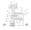
- FIG. 1 is a cross-sectional view of a motorcycle clutch device according to an embodiment of the present invention.
- FIG. 2 is a partial front view of the apparatus of FIG. 1.
- FIG. 2 is a partial cross-sectional view of the apparatus of FIG.
- FIG. 2 is a partial cross-sectional view of the apparatus of FIG. The figure which shows the relationship between the motion concerning a pressure plate, and the load concerning a friction surface.
- FIG. 1 is a cross-sectional view of a motorcycle clutch device as an example of a clutch device
- FIG. 2 is a front partial view of the motorcycle clutch device.
- axial direction indicates the left-right direction in FIG. 1
- axially inner first side
- second side indicates the left side of FIG. 1
- axially outer second side
- the motorcycle clutch device transmits power from the crankshaft of the engine to a transmission and interrupts power transmission by operating a release mechanism.
- the clutch device includes a clutch housing 1, a clutch shoe 2, an output member 3, and a clutch control unit 4.
- the clutch housing 1 has a disc portion 6 and a cylindrical portion 7 and is connected to an input gear 8.
- the input gear 8 meshes with a drive gear (not shown) fixed to the crankshaft on the engine side, and power is input from the engine.
- a hole 6a into which a transmission shaft is inserted is formed in the center portion. Further, a plurality of protrusions 6b protruding inward in the axial direction are formed at a predetermined interval in the circumferential direction at the radial intermediate portion of the disk portion 6. An elastic member 10 is mounted around the protrusion 6 b, and the protrusion 6 b and the elastic member 10 are inserted into a hole 8 a formed in the input gear 8.
- a spring support portion 6 c is formed at the radial intermediate portion of the disc portion 6.
- the spring 12 is supported by the spring support portion 6 c and the support plate 11 fixed to the side surface of the input gear 8.
- the spring 12 elastically connects the clutch housing 1 and the input gear 8 in the rotational direction.
- the support plate 11 is fixed to the tip of the protrusion 6b of the clutch housing 1 by a bolt 13 and a nut 14.
- a disc spring 15 is disposed on the inner peripheral portion of the support plate 11 between the side surface of the input gear 8.
- the cylindrical portion 7 is formed so as to extend outward from the outer peripheral edge of the disc portion 6 in the axial direction.
- a plurality of notches 7a (housing side engaging portions) extending in the axial direction and opening outward in the axial direction are formed in the cylindrical portion 7 at predetermined intervals in the circumferential direction.
- the clutch shoe 2 has a first clutch shoe 201 (first pressure receiving portion) and a second clutch shoe 202 (second pressure receiving portion) divided into two.
- the first clutch shoe 201 and the second clutch shoe 202 are annular members, respectively, and are arranged along the inner peripheral surface of the cylindrical portion 7 of the clutch housing 1. Further, the first clutch shoe 201 is disposed on the outer side in the axial direction, and the second clutch shoe 202 is disposed on the inner side in the axial direction.
- the first clutch shoe 201 and the second clutch shoe 202 are arranged so as to ensure a gap in the axial direction when no power is transmitted (when the clutch is off).
- the first clutch shoe 201 includes a plurality of claws 201a (a shoe side engaging portion), a first pressure receiving surface 201b, and a plurality of first accommodating portions 201c. Yes.
- the plurality of claws 201a are formed on the outer peripheral surface of the first clutch shoe 201 so as to protrude further to the outer peripheral side.
- the plurality of claws 201 a are arranged at predetermined intervals in the circumferential direction, and each claw 201 a is engaged with a notch 7 a formed in the cylindrical portion 7 of the clutch housing 1.
- the first clutch shoe 201 is movable in the axial direction with respect to the clutch housing 1 and is not rotatable.
- the first pressure receiving surface 201b is formed on the inner peripheral surface of the first clutch shoe 201 in a tapered shape whose diameter decreases from the axially outer end surface toward the axially inner side.
- Each of the plurality of first accommodating portions 201c is a circular recess, and is formed at a predetermined depth from the end surface on the outer side in the axial direction to the inner side in the axial direction.
- the second clutch shoe 202 has a plurality of claws 202a (shoe side engaging portions), a second pressure receiving surface 202b, and a plurality of second accommodating portions 202c. .
- the plurality of claws 202a are formed on the outer peripheral surface of the second clutch shoe 202 so as to protrude further to the outer peripheral side.
- the plurality of claws 202 a are arranged at predetermined intervals in the circumferential direction, and each claw 202 a is engaged with a notch 7 a formed in the tubular portion 7 of the clutch housing 1.
- the second clutch shoe 202 is movable in the axial direction with respect to the clutch housing 1 and is not rotatable.
- the second pressure receiving surface 202b is formed on the inner peripheral surface of the second clutch shoe 202 in a tapered shape whose diameter decreases from the axially inner end surface toward the axially outer side.
- the plurality of second accommodating portions 202 c are formed at positions corresponding to the first accommodating portions 201 c of the first clutch shoe 201.
- the 2nd accommodating part 202c is a circular recessed part, and is formed in the axial direction outer side by the predetermined
- a coil spring 9 (elastic member) for shock reduction is accommodated.
- the end surfaces of the first clutch shoe 201 and the second clutch shoe 202 come into contact with each other before the spring 9 comes into close contact. It has become.
- the output member 3 is housed in the inner peripheral portion of the clutch housing 1, and includes a clutch center 21 (first output member), a pressure plate 22 (second output member), and a hub 23.
- the clutch center 21 and the pressure plate 22 are both formed by sheet metal processing of an iron plate material.
- the clutch center 21 has a disc part 21 a and a friction part 21 b (first friction part).
- a spline hole 21c is formed in the central portion of the disc portion 21a, and the spline engagement is possible with the transmission shaft.
- four through holes 21d are formed at predetermined intervals in the circumferential direction in the radial direction intermediate portion of the disc portion 21a.
- the friction part 21b is formed by bending the outer peripheral part of the disk part 21a outward in the axial direction.
- the friction part 21b faces the first pressure receiving surface 201b of the first clutch shoe 201 and is formed in a tapered shape having the same inclination as the first pressure receiving surface 201b.
- An annular first friction material 25 is fixed to the outer peripheral surface of the friction portion 21b, and the surface of the first friction material 25 is a first friction surface 25a.
- the pressure plate 22 is disposed on the inner side in the axial direction of the clutch center 21 so as to be opposed to the clutch center 21 and movable in the axial direction.
- the pressure plate 22 has a disc part 22a and a friction part 22b (second friction part).
- a spline hole 22c is formed at the center of the disc portion 22a.
- four through holes 22d are formed at predetermined intervals in the circumferential direction in the inner peripheral portion of the disc portion 22a.
- the friction portion 22b is formed by bending the outer peripheral portion of the disc portion 22a inward in the axial direction.
- the friction portion 22b is opposed to the second pressure receiving surface 202b of the second clutch shoe 202, and is formed in a tapered shape having the same inclination as the second pressure receiving surface 202b.
- An annular second friction material 26 is fixed to the outer peripheral surface of the friction portion 22b, and the surface of the second friction material 26 is a second friction surface 26a.
- the first and second friction materials 25 and 26 are made of the same material, and here, a friction material for a four-wheeled vehicle used for a passenger car or the like is used.
- the hub 23 is an annular member, and is disposed on the inner peripheral portion of the pressure plate 22 so as to abut on the side surface on the inner side in the axial direction of the inner peripheral portion of the clutch center 21.
- the spline hole 23a is formed in the inner peripheral part of the hub 23, and the spline shaft 23b is formed in the outer peripheral surface.
- the spline hole 23a can be engaged with a transmission shaft.
- the spline shaft 23 b is engaged with the spline hole 22 c of the pressure plate 22.
- the spline hole 22c of the pressure plate 22 and the spline shaft 23b of the hub 23 mesh with each other so as to be slidable in the axial direction.
- the clutch center 21 can be connected to the transmission shaft through the spline hole 21c, and the pressure plate 22 can be connected to the transmission shaft through the spline engagement with the hub 23. Therefore, the clutch center 21 and the pressure plate 22 rotate in synchronization.
- a thrust plate 27 is disposed between the side surface of the hub 23 and the side surface of the inner peripheral portion of the clutch housing 1 as shown in FIG.
- first and second cone clutches C1, C2 In the configuration as described above, the first clutch shoe 201 having the first pressure receiving surface 201b and the first friction material 25 having the friction portion 21b and the first friction surface 25a formed on the outer peripheral portion of the clutch center 21 are provided. A first cone clutch C1 is configured.
- the second cone clutch C2 includes the second clutch shoe 202 having the second pressure receiving surface 202b and the second friction material 26 having the friction portion 22b and the second friction surface 26a formed on the outer peripheral portion of the pressure plate 22. Is configured.
- the clutch control unit 4 is disposed outside the clutch center 21 in the axial direction, and includes a release member 30 and four coil springs 40 (biasing members).
- the release member 30 is moved in the axial direction by a release mechanism (not shown).
- the release member 30 has an annular main body 31 and four protrusions 32.
- the annular main body 31 can be penetrated by a rod of a release mechanism or the like through an inner peripheral portion.
- the protrusion 32 is formed integrally with the main body 31 and protrudes inward in the axial direction from the main body 31.
- the protrusion 32 penetrates the through hole 21d of the clutch center 21 toward the pressure plate 22 side.
- the protrusion 32 has a screw hole 32a having a predetermined depth at the tip end on the inner side in the axial direction.
- the tip end surface of the protrusion 32 is in contact with the axially outer side surface of the pressure plate 22.
- a bolt 34 extending outward in the axial direction from the side surface on the inner side in the axial direction of the pressure plate 22 through the through hole 22 d is screwed into the screw hole 32 a of the protrusion 32. Thereby, the release member 30 is fixed to the pressure plate 22.
- the coil spring 40 is disposed so as to surround the outer periphery of the protrusion 32 of the release member 30 as shown in FIGS. That is, the protrusion 32 passes through the inner peripheral portion of the coil spring 40.
- One end of the coil spring 40 is in contact with the main body 31 of the release member 30, and the other end is in contact with the clutch center 21.
- the coil spring 40 is mounted between the release member 30 and the clutch center 21 in a compressed state in a neutral state where no release operation is performed. For this reason, the coil spring 40 urges the clutch center 21 in the axial direction and urges the pressure plate 22 in the axial direction.
- the torque transmitted to the clutch center 21 as described above is transmitted to the transmission shaft through the spline hole 21c of the clutch center 21.
- the torque transmitted to the pressure plate 22 is transmitted from the pressure plate 22 to the transmission shaft via the hub 23.
- the release member 30 is moved inward in the axial direction against the urging force of the coil spring 40.
- the pressure plate 22 fixed to the release member 30 also moves inward in the axial direction.
- the pressing force of the pressure plate 22 on the second clutch shoe 202 (second pressure receiving surface 202b) is released.
- the clutch center 21 is restricted from moving inward in the axial direction by the hub 23, the first pressure receiving force of the first clutch shoe 201 is released when the pressing force of the pressure plate 22 to the second clutch shoe 202 is released.
- the pressing force between the surface 201b and the first friction surface 25a is also released.
- the first cone clutch C1 and the second cone clutch C2 are clutch-off (release of power transmission: cutoff). In this clutch-off state, rotation from the clutch housing 1 is not transmitted to the clutch center 21 and the pressure plate 22.
- the solid line indicates the characteristic according to the present embodiment, and the broken line indicates the characteristic when no spring for reducing shock is provided.
- the second clutch shoe 202 and the first clutch shoe 201 come into contact with each other. Accordingly, the first clutch shoe 201 is also pressed outward in the axial direction, and pressing of the first pressure receiving surface 201b and the first friction surface 25a of the first clutch shoe 201 is started from this point (P2 in FIG. 5). Then, the two friction surfaces 25a and 26a are pressed against the corresponding pressure receiving surfaces 201b and 220b, respectively, and the first cone clutch C1 and the second cone clutch C2 are completely turned on.
- the first cone clutch C1 is configured using a part of the clutch center 21 and the second cone clutch C2 is configured using a part of the pressure plate 22.
- the pressure plate and the cone clutch may be configured separately.
- the coil spring is disposed as the elastic member between the first clutch shoe 201 and the second clutch shoe 202.
- another elastic member such as a cone spring may be disposed.
- the first clutch shoe 201 and the second clutch shoe 202 are provided with the accommodating portions 201c and 202c, respectively, and the elastic member is accommodated in the accommodating portion. It is not limited to.
- the torque transmission capacity can be increased and the shock when the clutch is on can be reduced.
Landscapes
- Engineering & Computer Science (AREA)
- General Engineering & Computer Science (AREA)
- Mechanical Engineering (AREA)
- Mechanical Operated Clutches (AREA)
Applications Claiming Priority (2)
| Application Number | Priority Date | Filing Date | Title |
|---|---|---|---|
| JP2016-194188 | 2016-09-30 | ||
| JP2016194188A JP2018054094A (ja) | 2016-09-30 | 2016-09-30 | クラッチ装置 |
Publications (1)
| Publication Number | Publication Date |
|---|---|
| WO2018061628A1 true WO2018061628A1 (ja) | 2018-04-05 |
Family
ID=61763474
Family Applications (1)
| Application Number | Title | Priority Date | Filing Date |
|---|---|---|---|
| PCT/JP2017/031715 Ceased WO2018061628A1 (ja) | 2016-09-30 | 2017-09-04 | クラッチ装置 |
Country Status (2)
| Country | Link |
|---|---|
| JP (1) | JP2018054094A (enExample) |
| WO (1) | WO2018061628A1 (enExample) |
Citations (2)
| Publication number | Priority date | Publication date | Assignee | Title |
|---|---|---|---|---|
| GB410380A (en) * | 1932-10-08 | 1934-05-17 | Gustave Fast Engineering Corp | Improvements in or relating to friction clutches |
| JPH04362315A (ja) * | 1991-06-06 | 1992-12-15 | Kubota Corp | 多板クラッチ |
-
2016
- 2016-09-30 JP JP2016194188A patent/JP2018054094A/ja not_active Ceased
-
2017
- 2017-09-04 WO PCT/JP2017/031715 patent/WO2018061628A1/ja not_active Ceased
Patent Citations (2)
| Publication number | Priority date | Publication date | Assignee | Title |
|---|---|---|---|---|
| GB410380A (en) * | 1932-10-08 | 1934-05-17 | Gustave Fast Engineering Corp | Improvements in or relating to friction clutches |
| JPH04362315A (ja) * | 1991-06-06 | 1992-12-15 | Kubota Corp | 多板クラッチ |
Also Published As
| Publication number | Publication date |
|---|---|
| JP2018054094A (ja) | 2018-04-05 |
Similar Documents
| Publication | Publication Date | Title |
|---|---|---|
| US12398767B2 (en) | Power transmission apparatus | |
| JP5272089B1 (ja) | モータサイクル用クラッチ装置 | |
| US11754130B2 (en) | Power transmission apparatus | |
| JP6516756B2 (ja) | 動力伝達装置 | |
| JP6961427B2 (ja) | 動力伝達装置 | |
| WO2016143370A1 (ja) | クラッチ装置 | |
| US11835097B2 (en) | Power transmission apparatus | |
| CN115628269B (zh) | 动力传递装置 | |
| JP7161285B2 (ja) | クラッチ装置 | |
| JP4975723B2 (ja) | モータサイクル用クラッチ装置 | |
| CN101175928B (zh) | 摩托车用离合器装置 | |
| WO2018061626A1 (ja) | モータサイクル用クラッチ装置 | |
| JP2018054094A (ja) | クラッチ装置 | |
| JP6636408B2 (ja) | クラッチ装置 | |
| WO2018061627A1 (ja) | クラッチ装置 | |
| WO2018061639A1 (ja) | モータサイクル用クラッチ装置 | |
| JP6700733B2 (ja) | クラッチ装置 | |
| JP6539121B2 (ja) | クラッチ装置 | |
| JP6322619B2 (ja) | クラッチ装置 | |
| JP3892878B2 (ja) | モータサイクル用クラッチ装置 | |
| JP2006312992A (ja) | モータサイクル用クラッチ装置 |
Legal Events
| Date | Code | Title | Description |
|---|---|---|---|
| 121 | Ep: the epo has been informed by wipo that ep was designated in this application |
Ref document number: 17855586 Country of ref document: EP Kind code of ref document: A1 |
|
| NENP | Non-entry into the national phase |
Ref country code: DE |
|
| 122 | Ep: pct application non-entry in european phase |
Ref document number: 17855586 Country of ref document: EP Kind code of ref document: A1 |