WO2018056307A1 - 空気電池およびパッチ - Google Patents
空気電池およびパッチ Download PDFInfo
- Publication number
- WO2018056307A1 WO2018056307A1 PCT/JP2017/033912 JP2017033912W WO2018056307A1 WO 2018056307 A1 WO2018056307 A1 WO 2018056307A1 JP 2017033912 W JP2017033912 W JP 2017033912W WO 2018056307 A1 WO2018056307 A1 WO 2018056307A1
- Authority
- WO
- WIPO (PCT)
- Prior art keywords
- air battery
- electrolyte
- salt
- positive electrode
- separator
- Prior art date
- Legal status (The legal status is an assumption and is not a legal conclusion. Google has not performed a legal analysis and makes no representation as to the accuracy of the status listed.)
- Ceased
Links
Images

Classifications
-
- H—ELECTRICITY
- H01—ELECTRIC ELEMENTS
- H01M—PROCESSES OR MEANS, e.g. BATTERIES, FOR THE DIRECT CONVERSION OF CHEMICAL ENERGY INTO ELECTRICAL ENERGY
- H01M12/00—Hybrid cells; Manufacture thereof
- H01M12/04—Hybrid cells; Manufacture thereof composed of a half-cell of the fuel-cell type and of a half-cell of the primary-cell type
- H01M12/06—Hybrid cells; Manufacture thereof composed of a half-cell of the fuel-cell type and of a half-cell of the primary-cell type with one metallic and one gaseous electrode
- H01M12/065—Hybrid cells; Manufacture thereof composed of a half-cell of the fuel-cell type and of a half-cell of the primary-cell type with one metallic and one gaseous electrode with plate-like electrodes or stacks of plate-like electrodes
-
- H—ELECTRICITY
- H01—ELECTRIC ELEMENTS
- H01M—PROCESSES OR MEANS, e.g. BATTERIES, FOR THE DIRECT CONVERSION OF CHEMICAL ENERGY INTO ELECTRICAL ENERGY
- H01M12/00—Hybrid cells; Manufacture thereof
- H01M12/04—Hybrid cells; Manufacture thereof composed of a half-cell of the fuel-cell type and of a half-cell of the primary-cell type
- H01M12/06—Hybrid cells; Manufacture thereof composed of a half-cell of the fuel-cell type and of a half-cell of the primary-cell type with one metallic and one gaseous electrode
-
- H—ELECTRICITY
- H01—ELECTRIC ELEMENTS
- H01M—PROCESSES OR MEANS, e.g. BATTERIES, FOR THE DIRECT CONVERSION OF CHEMICAL ENERGY INTO ELECTRICAL ENERGY
- H01M12/00—Hybrid cells; Manufacture thereof
- H01M12/02—Details
-
- H—ELECTRICITY
- H01—ELECTRIC ELEMENTS
- H01M—PROCESSES OR MEANS, e.g. BATTERIES, FOR THE DIRECT CONVERSION OF CHEMICAL ENERGY INTO ELECTRICAL ENERGY
- H01M50/00—Constructional details or processes of manufacture of the non-active parts of electrochemical cells other than fuel cells, e.g. hybrid cells
- H01M50/40—Separators; Membranes; Diaphragms; Spacing elements inside cells
- H01M50/409—Separators, membranes or diaphragms characterised by the material
-
- H—ELECTRICITY
- H01—ELECTRIC ELEMENTS
- H01M—PROCESSES OR MEANS, e.g. BATTERIES, FOR THE DIRECT CONVERSION OF CHEMICAL ENERGY INTO ELECTRICAL ENERGY
- H01M50/00—Constructional details or processes of manufacture of the non-active parts of electrochemical cells other than fuel cells, e.g. hybrid cells
- H01M50/40—Separators; Membranes; Diaphragms; Spacing elements inside cells
- H01M50/489—Separators, membranes, diaphragms or spacing elements inside the cells, characterised by their physical properties, e.g. swelling degree, hydrophilicity or shut down properties
- H01M50/491—Porosity
-
- A—HUMAN NECESSITIES
- A61—MEDICAL OR VETERINARY SCIENCE; HYGIENE
- A61B—DIAGNOSIS; SURGERY; IDENTIFICATION
- A61B2560/00—Constructional details of operational features of apparatus; Accessories for medical measuring apparatus
- A61B2560/02—Operational features
- A61B2560/0204—Operational features of power management
- A61B2560/0214—Operational features of power management of power generation or supply
-
- A—HUMAN NECESSITIES
- A61—MEDICAL OR VETERINARY SCIENCE; HYGIENE
- A61B—DIAGNOSIS; SURGERY; IDENTIFICATION
- A61B5/00—Measuring for diagnostic purposes; Identification of persons
- A61B5/68—Arrangements of detecting, measuring or recording means, e.g. sensors, in relation to patient
- A61B5/6801—Arrangements of detecting, measuring or recording means, e.g. sensors, in relation to patient specially adapted to be attached to or worn on the body surface
- A61B5/683—Means for maintaining contact with the body
- A61B5/6832—Means for maintaining contact with the body using adhesives
- A61B5/6833—Adhesive patches
-
- H—ELECTRICITY
- H01—ELECTRIC ELEMENTS
- H01M—PROCESSES OR MEANS, e.g. BATTERIES, FOR THE DIRECT CONVERSION OF CHEMICAL ENERGY INTO ELECTRICAL ENERGY
- H01M2300/00—Electrolytes
- H01M2300/0002—Aqueous electrolytes
- H01M2300/0005—Acid electrolytes
-
- H—ELECTRICITY
- H01—ELECTRIC ELEMENTS
- H01M—PROCESSES OR MEANS, e.g. BATTERIES, FOR THE DIRECT CONVERSION OF CHEMICAL ENERGY INTO ELECTRICAL ENERGY
- H01M2300/00—Electrolytes
- H01M2300/0017—Non-aqueous electrolytes
- H01M2300/0025—Organic electrolyte
-
- Y—GENERAL TAGGING OF NEW TECHNOLOGICAL DEVELOPMENTS; GENERAL TAGGING OF CROSS-SECTIONAL TECHNOLOGIES SPANNING OVER SEVERAL SECTIONS OF THE IPC; TECHNICAL SUBJECTS COVERED BY FORMER USPC CROSS-REFERENCE ART COLLECTIONS [XRACs] AND DIGESTS
- Y02—TECHNOLOGIES OR APPLICATIONS FOR MITIGATION OR ADAPTATION AGAINST CLIMATE CHANGE
- Y02E—REDUCTION OF GREENHOUSE GAS [GHG] EMISSIONS, RELATED TO ENERGY GENERATION, TRANSMISSION OR DISTRIBUTION
- Y02E60/00—Enabling technologies; Technologies with a potential or indirect contribution to GHG emissions mitigation
- Y02E60/10—Energy storage using batteries
Definitions
- the present invention relates to an air battery having a small environmental load and good discharge characteristics, and a patch including the air battery.
- Patent Document 1 an aqueous solution of an alkali metal hydroxide such as an aqueous potassium hydroxide solution that is strongly alkaline is widely used as an electrolyte (Patent Document 1, etc.).
- Patent Document 2 an aqueous solution having a lower pH (such as a sodium chloride aqueous solution) is used as an electrolyte for an air battery (eg, Patent Document 2). It is also conceivable to reduce the environmental load.
- JP 2016-46116 A (paragraph [0068], Example (paragraph [0073]) JP 2016-146257 A (paragraph [0015])
- the present invention has been made in view of the above circumstances, and an object thereof is to provide an air battery having a small environmental load and good discharge characteristics, and a patch including the air battery.
- the air battery of the present invention that has achieved the above-mentioned object has a positive electrode having a catalyst layer containing a catalyst and a binder, a negative electrode containing a metal material, a separator, and an electrolytic solution accommodated in an exterior body,
- the air permeability is 10 sec / 100 ml or more
- the electrolytic solution is an aqueous solution having a pH of 3 or more and less than 12.
- a positive electrode having a catalyst layer containing a catalyst and a binder, a negative electrode containing a metal material, a separator and an electrolytic solution are accommodated in an exterior body,
- the positive electrode has a carbon porous sheet as a current collector, and the electrolytic solution is an aqueous solution having a pH of 3 or more and less than 12.
- the patch of the present invention can be worn on the body and includes the air battery of the present invention as a power source.
- an air battery having a small environmental load and good discharge characteristics it is possible to provide an air battery having a small environmental load and good discharge characteristics, and a patch including the air battery.
- an aqueous solution having a pH of 3 or more and less than 12 is used as an electrolytic solution, compared with a case where a strongly alkaline aqueous solution (pH of about 14) such as a potassium hydroxide aqueous solution that has been conventionally used as an electrolytic solution is used.
- a strongly alkaline aqueous solution pH of about 14
- a potassium hydroxide aqueous solution that has been conventionally used as an electrolytic solution
- the dependence of the discharge characteristics on the air permeability of the separator is not recognized in the air battery having a strongly alkaline electrolyte, and is considered to be peculiar to the air battery using an electrolyte having a constant pH or lower. .
- the air permeability of the separator used in the air battery of the present invention may be 10 sec / 100 ml or more, preferably 200 sec / 100 ml or more, more preferably 400 sec / 100 ml or more, and 1000 sec / 100 ml. The above is most preferable.
- the separator used for the air battery of this invention should just be an ion permeability which the ion required for discharge reaction permeate
- the air permeability of the separator and the air permeability of the carbon sheet described later are values obtained by the Gurley method defined in JIS P 8117.
- separator As a separator that satisfies the above air permeability, it is used in various batteries such as air batteries such as resin porous membranes (microporous membrane, nonwoven fabric, etc.) and semipermeable membranes typified by cellophane films. A separator that satisfies the conditions can be selected and used.
- Examples of the resin constituting the separator made of a resin porous membrane include polyolefins such as polyethylene (PE), polypropylene (PP), and ethylene-propylene copolymer, and polyesters such as polyethylene terephthalate.
- polyolefins such as polyethylene (PE), polypropylene (PP), and ethylene-propylene copolymer
- polyesters such as polyethylene terephthalate.
- the air permeability can be adjusted by adjusting the porosity (porosity) and the curvature of the pores (voids).
- the porosity is preferably 30 to 80%, and the thickness is preferably 10 to 100 ⁇ m.
- a semipermeable membrane such as a cellophane film is preferably used for improving discharge characteristics in the present invention because it allows only a part of the components in the electrolytic solution to pass therethrough.
- the separator may be composed of only the semipermeable membrane.
- the separator since the semipermeable membrane has low strength, problems such as breakage during battery assembly are likely to occur. Therefore, it is also recommended that the separator be composed of a laminate in which a graft film composed of a specific polymer and a semipermeable membrane are laminated.
- the graft polymer constituting the graft film has, for example, a form in which (meth) acrylic acid or a derivative thereof is graft-polymerized on a polyolefin (polyethylene, polypropylene, etc.) that is a trunk polymer.
- the graft polymer may have the above-described form, and may not be produced by a method in which (meth) acrylic acid or a derivative thereof is graft polymerized to polyolefin.
- the (meth) acrylic acid or its derivative constituting the graft polymer is represented by the following general formula (1).
- R 1 is H or CH 3
- R 2 is a hydrophilic substituent such as H or NH 4 , Na, K, Rb, Cs.
- the above-mentioned graft film and cellophane film have a function in which the polymer itself constituting these films absorbs the electrolytic solution and transmits ions.
- the graft polymer constituting the graft film preferably has a graft rate defined by the following formula (2) of 160% or more. Since there is a correlation between the graft ratio of the graft polymer and the electrical resistance of the graft film, by using a graft polymer having a graft ratio as described above, the electrical resistance of the graft film is 20 to 120 m ⁇ ⁇ in 2. Can be controlled to be a preferable value.
- the electrical resistance of the graft film is a value obtained by an alternating voltage drop method (1 kHz).
- the film is immersed in an aqueous solution of 40% KOH (specific gravity: 1.400 ⁇ 0.005) at 25 ⁇ 1 ° C., taken out after 5 to 15 hours, and the electrical resistance is measured. Good.
- A is the mass (g) of the graft polymer
- B is the mass (g) of the trunk polymer in the graft polymer.
- B (mass of the trunk polymer in the graft polymer)” in the formula (2) is, for example, graft polymerization of the graft polymer to the polyolefin as the trunk polymer with (meth) acrylic acid or a derivative thereof.
- the mass of the trunk polymer used for the graft polymerization may be measured in advance.
- the graft ratio may exceed 100% when the monomers [(meth) acrylic acid and its derivatives] used for graft polymerization are polymerized and the graft molecule becomes a long chain. Because there is.
- the upper limit of the graft ratio of the graft polymer defined by the formula (2) is preferably 400%.
- the “(meth) acrylic acid” is a collective expression of acrylic acid and methacrylic acid.
- the thickness is preferably 15 ⁇ m or more, preferably 40 ⁇ m or less, and more preferably 30 ⁇ m or less.
- the total thickness of the graft film and the cellophane film is, for example, preferably 30 ⁇ m or more, more preferably 40 ⁇ m or more, 100 ⁇ m or less, more preferably 70 ⁇ m or less, and most preferably 60 ⁇ m or less.
- the thickness of the graft film is, for example, preferably 15 ⁇ m or more, more preferably 25 ⁇ m or more, and 50 ⁇ m or less. Is preferable, and it is more preferable that it is 30 micrometers or less.
- Examples of the laminate of the graft film and cellophane film for constituting the separator include those commercially available under the names “YG9132”, “YG9122”, and “YG2152” from Yuasa Membrane System Co., Ltd.
- the separator may be constituted by combining cellophane film, cellophane film and graft film, and liquid absorbing layer (electrolyte holding layer) such as vinylon-rayon mixed paper.
- the thickness of such a liquid absorbing layer is preferably 20 to 500 ⁇ m.
- the electrolyte solution according to the air battery of the present invention has a pH of 3 or more, preferably 3.5 or more, more preferably 4 or more, particularly preferably 5 or more, and less than 12, preferably 10 or less, more preferably.
- the aqueous solution is 8 or less, particularly preferably 6.5 or less.
- the electrolyte used to form the aqueous solution used as the electrolyte includes chlorides such as sodium chloride, potassium chloride, magnesium chloride, calcium chloride, ammonium chloride, and zinc chloride; alkaline earth metal hydroxides (magnesium hydroxide, Calcium hydroxide), acetate (sodium acetate, potassium acetate, magnesium acetate, etc.), nitrate (sodium nitrate, potassium nitrate, magnesium nitrate, etc.), sulfate (sodium sulfate, potassium sulfate, magnesium sulfate, etc.), phosphate ( Sodium phosphate, potassium phosphate, magnesium phosphate, etc.), borate (sodium borate, potassium borate, magnesium borate, etc.), citrate (sodium citrate, potassium citrate, magnesium citrate, etc.), Glutamate (glutamine Sodium, potassium glutamate, magnesium glutamate, etc.); alkali metal bicarbonates (so
- Water-soluble zinc compounds such as zinc chloride used in electrolytes for manganese dry batteries and alkali metal hydroxides such as potassium hydroxide used in electrolytes for air batteries have strong skin irritation. If the electrolyte leaks and adheres to the body, it may cause troubles such as inflammation on the skin. For this reason, when considering application to the power source of a medical / health device that is used in close contact with the body, it is desirable to have an electrolyte solution configuration that has a small effect on the skin.
- the compound is not normally regarded as a “deleterious substance”, but considering such a case, the content of the compound designated as the “deleterious substance” is 0.5% by mass or less. Desirably, it is more desirably 0.1% by mass or less, and particularly desirably 0.01% by mass or less.
- the above-mentioned “compound designated as a deleterious substance” refers to a compound stipulated in Appendix 2 of the “Poisonous and Deleterious Substances Control Law” and “Ordinance for Enforcement of the Poisonous and Deleterious Substances Control Law” Article 2.
- a salt formed of a strong acid and a weak base as the electrolyte.
- the strong acid include hydrochloric acid, sulfuric acid, nitric acid and perchloric acid
- the weak base include hydroxides of metal elements other than alkali metals, such as aluminum hydroxide and magnesium hydroxide, and ammonia. Is done.
- At least one selected from Cl ⁇ , SO 4 2 ⁇ , HSO 4 ⁇ and NO 3 ⁇ is used because it has a small effect on the skin and can reduce the environmental burden when discarded.
- a salt of a seed ion and at least one ion selected from Al ion, Mg ion, Fe ion and ammonium ion is preferably used.
- the salt include ammonium salts such as ammonium sulfate, ammonium hydrogen sulfate [(NH 4 ) HSO 4 ], ammonium chloride, and ammonium nitrate; aluminum salts such as aluminum sulfate, aluminum chloride, and aluminum nitrate; magnesium sulfate, chloride Magnesium, magnesium chloride such as magnesium chloride [MgCl (OH)], magnesium nitrate; iron (II) sulfate, iron (II) sulfate [(NH 4 ) 2 Fe (SO 4 ) 2 ], iron (III) sulfate And iron salts such as iron (II) chloride and iron (II) nitrate. Two or more of these electrolytes may be contained in the electrolytic solution.
- ammonium salts such as ammonium sulfate, ammonium hydrogen sulfate [(NH 4 ) HSO 4 ], ammonium chloride, and ammonium nitrate
- An aqueous solution containing a salt of a strong acid and a weak base has a function of corroding a metal material such as zinc or a zinc alloy as a negative electrode active material, compared to an aqueous solution containing a salt of a strong acid and a strong base such as sodium chloride. Relatively small. Further, among strong acid salts, an aqueous solution containing a salt or ammonium salt of a metal element selected from Al, Mg and Fe has a relatively high conductivity as compared with, for example, an aqueous zinc chloride solution.
- a salt of a strong acid and a weak base at least one ion selected from Cl ⁇ , SO 4 2 ⁇ , HSO 4 ⁇ and NO 3 ⁇ and an Al ion, Mg ion, Fe ion and ammonium ion are used.
- an aqueous solution containing a salt with at least one selected ion as the electrolyte it is possible to ensure good discharge characteristics and maintain the characteristics for a long period of time.
- Cl - for the salt ions and Fe 3+ ions [iron (III) chloride] a strong action can corrode metal materials is a negative electrode active material as compared with the salts according to the combination of other ions, Cl - ions It is preferable to use iron (II) chloride [FeCl 2 ] as the salt of Fe ions. Moreover, since the effect
- perchlorate is prone to combustion and explosion due to heating and impact, so from the standpoint of reducing environmental impact and ensuring safety during disposal, perchlorate must be included in the electrolyte. It is preferable to use a salt other than the acid salt, and when the electrolytic solution contains a perchlorate ion, the content is preferably less than 100 ppm, and more preferably less than 10 ppm.
- heavy metal salts represented by zinc chloride, copper sulfate, etc. are often harmful substances, so they are not suitable for environmental impact or disposal.
- the content of heavy metal ions excluding iron ions in the electrolytic solution is also preferably less than 100 ppm, and more preferably less than 10 ppm.
- the conductivity of the electrolytic solution is preferably 80 mS / cm or more, more preferably 150 mS / cm or more, and particularly preferably 200 mS / cm or more.
- the concentration of the electrolyte in the electrolytic solution should be within a range where the above-described conductivity can be secured. desirable.
- the concentration of the electrolyte in the electrolytic solution is usually about 5 to 50% by mass, and the conductivity of the electrolytic solution can be increased to about 700 mS / cm.
- the electrical conductivity of the electrolytic solution here is a value measured by the method employed in the examples described later.
- the concentration of dissolved oxygen involved in the corrosion reaction (oxidation reaction) in the electrolytic solution decreases, and the negative electrode active material and It can be expected that the corrosion reaction of the metal material or the positive electrode or negative electrode current collector is suppressed.
- the concentration of 3% by mass maximizes the effect of corroding the metal.
- the concentration of the electrolyte is increased further, the dissolved oxygen concentration in the electrolyte decreases. The progress of the metal oxidation reaction is suppressed.
- the concentration of the electrolyte in the electrolytic solution is increased, the temperature at which the electrolytic solution is solidified due to the action of lowering the freezing point is further lowered, so that improvement of discharge characteristics at a low temperature can be expected.
- the concentration of the electrolyte in the electrolytic solution is preferably 1 mol / l or more, and preferably 2 mol / l. More preferably, it is more preferably 3 mol / l or more.
- the saturation concentration at 20 ° C. is preferably 90% or less, for example, preferably 7 mol / l or less, and more preferably 5 mol / l or less.
- an indium compound or a tin compound is dissolved in the electrolytic solution.
- generation of hydrogen gas in the battery can be suppressed more favorably.
- Examples of the indium compound and tin compound to be dissolved in the electrolytic solution include hydroxides, oxides, sulfates, sulfides, nitrates, bromides, and chlorides.
- the concentration of the compound in the electrolytic solution is preferably 0.005% or more, more preferably 0.01% or more, particularly preferably 0.05% or more, based on mass. It is preferably 1% or less, more preferably 0.5% or less, and particularly preferably 0.1% or less.
- various known additives may be added to the electrolytic solution as necessary within a range not impairing the effects of the present invention.
- zinc oxide may be added in order to prevent corrosion (oxidation) of the metal material used for the negative electrode.
- Zinc oxide can also be added to the negative electrode.
- the electrolytic solution may be in a liquid form, or may be a so-called gel using a gelling agent.
- the gel electrolyte is used, the corrosion inhibiting effect of the negative electrode active material is further improved.
- a metal or alloy foil as a negative electrode active material can be used as it is for the negative electrode, but in this case, the negative electrode has a negative conductivity because the foil is broken by corrosion by the electrolytic solution. The capacity may not be extracted sufficiently. Even when such a negative electrode is used, the use of the electrolytic solution having the above electrolyte concentration can suppress breakage of the foil as the negative electrode. However, when a gel electrolyte is used, the suppression effect is more effective. Since it improves, the fall of battery capacity can be suppressed more favorably.
- gelling agents examples include polyacrylic acids (polyacrylic acid, sodium polyacrylate, ammonium polyacrylate, etc.), celluloses (carboxymethylcellulose, methylcellulose, hydroxypropylcellulose, and alkalis thereof. Salt). Further, as disclosed in JP-A No. 2001-307746, crosslinked polyacrylic acid or a salt-type water-absorbing polymer thereof (for example, sodium polyacrylate, ammonium polyacrylate) and other gelling agents It is also preferable to use together.
- gelling agent used in combination with the cross-linked polyacrylic acid or its salt-type water-absorbing polymer examples include the aforementioned celluloses, cross-linked branched polyacrylic acid or its salts (for example, soda salt, ammonium salt, etc.). . These gelling agents may use only 1 type and may use 2 or more types together.
- carboxymethyl cellulose having a degree of etherification of 1.0 to 1.5 is preferable.
- the degree of etherification is a numerical value indicating how many carboxymethyl groups are ether-bonded with respect to one anhydroglucose unit. Since the CMC having the etherification degree has a high action of thickening the electrolytic solution, the use of the CMC makes it possible to easily prepare a gel electrolytic solution having better properties.
- the content of the gelling agent in the electrolytic solution is not particularly limited as long as it is an amount that allows the electrolytic solution to be gelled well, but usually about 0.1 to 5% by mass is preferable.
- the positive electrode (air electrode) of the air battery has a catalyst layer, and for example, a structure in which a catalyst layer and a current collector are laminated can be used.
- the catalyst layer can contain a catalyst, a binder, and the like.
- Examples of the catalyst related to the catalyst layer include silver, platinum group metals or alloys thereof, transition metals, platinum / metal oxides such as Pt / IrO 2 , perovskite oxides such as La 1-x Ca x CoO 3 , and WC. Carbides, nitrides such as Mn 4 N, manganese oxides such as manganese dioxide, carbon [graphite, carbon black (acetylene black, ketjen black, channel black, furnace black, lamp black, thermal black, etc.), charcoal, activated carbon Etc.], and one or more of these are used.
- the catalyst layer preferably has a heavy metal content of 1% by mass or less, excluding the components of the electrolytic solution.
- the heavy metal content in the catalyst layer as used herein can be measured by fluorescent X-ray analysis.
- fluorescent X-ray analysis For example, “ZSX100e” manufactured by Rigaku Corporation can be used, and measurement can be performed under the conditions of excitation source: Rh50 kV, analysis area: ⁇ 10 mm.
- a catalyst that does not contain heavy metals is recommended as the catalyst for the catalyst layer, and it is more preferable to use the above-mentioned various carbons.
- the specific surface area of the carbon used as the catalyst is preferably 200 m 2 / g or more, more preferably 300 m 2 / g or more, and 500 m 2 / g. It is still more preferable that it is above.
- the specific surface area of carbon referred to in the present specification is a value determined by the BET method according to JIS K 6217. For example, a specific surface area measuring device by a nitrogen adsorption method (“Macsorb HM model-1201” manufactured by Mounttech) is used. Can be measured. In addition, the upper limit of the specific surface area of carbon is usually about 2000 m 2 / g.
- DBP oil absorption amount of carbon used as a catalyst is preferably 150 cm 3/100 g or more, more preferably 200 cm 3/100 g or more, 300 cm 3/100 g or more More preferably.
- the DBP oil absorption amount of carbon referred to in the present specification can be measured according to JIS K 6217 (values described in Examples below are values obtained by this method).
- DBP oil absorption of the carbon used as catalyst is less than 1000 cm 3/100 g it is preferred, more preferably 800 cm 3/100 g or less, and more preferably not more than 600 cm 3/100 g.
- the catalyst content in the catalyst layer is preferably 20 to 70% by mass.
- binder for the catalyst layer examples include a vinylidene fluoride polymer [polyvinylidene fluoride (PVDF)], a tetrafluoroethylene polymer [polytetrafluoroethylene (PTFE)], a vinylidene fluoride copolymer, and tetrafluoroethylene.
- PVDF polyvinylidene fluoride
- PTFE polytetrafluoroethylene
- VDF-HFP vinylidene fluoride-hexafluoropropylene copolymer
- PVDF-CTFE vinylidene fluoride-chlorotrifluoroethylene copolymer
- PVDF-TFE vinylidene fluoride-tetrafluoroethylene copolymer
- PVDF-TFE vinylidene fluoride-tetrafluoroethylene copolymer
- a fluororesin binder such as vinylidene fluoride-hexafluoropropylene-tetrafluoroethylene copolymer (PVDF-HFP-TFE).
- a tetrafluoroethylene polymer or copolymer is preferable, and PTFE is more preferable.
- the content of the binder in the catalyst layer is preferably 3 to 50% by mass.
- the thickness of the catalyst layer in the positive electrode is preferably 50 to 500 ⁇ m.
- Current collectors for the positive electrode include, for example, nets, foils, expanded metals, punching metals made of metal materials such as titanium, nickel, stainless steel, and copper; carbon sheets such as carbon paper, carbon cloth, and carbon felt (fiber A carbon porous sheet, such as a carbon sheet composed of glassy carbon, etc. can be used.
- a positive electrode current collector in an air battery a net made of a metal material such as stainless steel is generally used, and a strong alkaline (pH of about 14) aqueous solution such as an aqueous potassium hydroxide solution is used as an electrolytic solution.
- a strong alkaline (pH of about 14) aqueous solution such as an aqueous potassium hydroxide solution is used as an electrolytic solution.
- the current collector can function without any problem.
- the metal positive electrode current collector is easily corroded, and the discharge characteristics are deteriorated when the discharge current is increased. It becomes easy.
- a carbon current collector such as a porous sheet
- the carbon sheet may have a single-layer structure, or may have a multilayer structure in which carbon papers, carbon cloths, or carbon felts are laminated, and two types of carbon paper, carbon cloth, and carbon felt.
- a multilayer structure in which the above is laminated may be used.
- the carbon sheet may be integrated with a base made of a material other than carbon, and may constitute a porous current collector as a whole.
- the Gurley value representing the air permeability (thickness direction) of the carbon sheet is preferably 1 sec / 100 ml or more, preferably 5 sec / 100 ml or more, in order to prevent the porosity from becoming too high and the conductivity from decreasing. It is more preferable.
- the Gurley value of the carbon sheet is preferably 500 sec / 100 ml or less, and more preferably 200 sec / 100 ml or less in order to keep the porosity above a certain level and not to prevent the permeation of air.
- the fiber diameter of the fibrous carbon constituting the carbon sheet is usually about 2 to 30 ⁇ m.
- the thickness of the current collector relating to the positive electrode is preferably 10 to 500 ⁇ m, and is preferably 30 ⁇ m or more from the viewpoints of handleability and availability, and securing a sufficient current collecting function at the positive electrode. More preferably, it is 50 ⁇ m or more.
- the porosity of the carbon sheet is preferably 50% or more and 95% or less from the viewpoint of securing good air permeability and sufficient strength, and an appropriate one selected from commercially available products is used. do it.
- the catalyst layer can be produced, for example, by mixing the catalyst, binder and the like with water, rolling with a roll, and bringing the catalyst layer into close contact with the current collector.
- the catalyst layer forming composition slurry, paste, etc.
- it can also be manufactured through a step of performing a pressing process such as a calendar process.
- the negative electrode of the air battery includes a zinc-based material (referred to collectively as zinc material and zinc alloy material), a magnesium-based material (referred to collectively as magnesium material and magnesium alloy material), and an aluminum-based material.
- a material containing a metal material such as an aluminum material and an aluminum alloy material is collectively used.
- metals such as zinc, magnesium, and aluminum act as active materials.
- the metal material used for the negative electrode preferably has a low content of mercury, cadmium, lead and chromium, and the specific content is based on mass, More preferably, mercury: 0.1% ppm or less, cadmium: 0.01% ppm or less, lead: 0.1% ppm or less, and chromium: 0.1% ppm or less.
- zinc-based particles referred to collectively as zinc particles and zinc alloy particles
- magnesium-based particles referred to collectively as magnesium particles and magnesium alloy particles
- aluminum-based particles A negative electrode containing particles (aluminum particles and aluminum alloy particles are collectively referred to as such) can be used.
- the alloy component of the zinc alloy particles include indium (for example, the content is 0.005 to 0.05% by mass), bismuth (for example, the content is 0.005 to 0.05% by mass), aluminum (For example, the content is 0.001 to 0.15% by mass).
- Examples of the alloy component of the magnesium alloy particles include calcium (for example, the content is 1 to 3% by mass), manganese (for example, the content is 0.1 to 0.5% by mass), zinc (for example, Examples thereof include a content of 0.4 to 1% by mass and aluminum (for example, a content of 8 to 10% by mass).
- examples of the alloy component of the aluminum alloy particles include zinc (for example, the content is 0.5 to 10% by mass), tin (for example, the content is 0.04 to 1.0% by mass), gallium (For example, the content is 0.003 to 1.0% by mass), silicon (for example, the content is 0.05% or less by mass), iron (for example, the content is 0.1% or less by mass), Examples include magnesium (for example, the content is 0.1 to 2.0% by mass), manganese (for example, the content is 0.01 to 0.5% by mass), and the like.
- the metal particles may be used alone or in combination of two or more.
- the ratio of particles having a particle size of 75 ⁇ m or less is preferably 50% by mass or less, more preferably 30% by mass or less, and the particle size is 100 to 100%.
- grains of 200 micrometers is 50 mass% or more, More preferably, it is 90 mass% or more is mentioned.
- the particle size of the magnesium-based particles and aluminum-based particles is, for example, preferably 50% by mass or less, more preferably 30% by mass or less, of all particles having a particle size of 30 ⁇ m or less,
- the ratio of particles having a particle size of 50 to 200 ⁇ m is 50% by mass or more, more preferably 90% by mass or more.
- the particle size of the metal particles is measured by using a laser scattering particle size distribution analyzer (for example, “LA-920” manufactured by HORIBA, Ltd.) and measuring these particles by dispersing them in a medium in which the particles are not dissolved.
- the particle size (D 50 ) at a cumulative frequency of 50%.
- a gelling agent sodium polyacrylate, carboxymethyl cellulose, etc.
- a binder that is added as necessary may be included, and it is configured by adding an electrolytic solution thereto.
- a negative electrode agent (such as a gelled negative electrode) can be used.
- the amount of the gelling agent in the negative electrode is preferably 0.5 to 1.5% by mass, for example, and the amount of the binder is preferably 0.5 to 3% by mass.
- the same electrolyte as that injected into the battery can be used.
- the content of the metal particles in the negative electrode is, for example, preferably 60% by mass or more, more preferably 65% by mass or more, and preferably 95% by mass or less, and 90% by mass or less. It is more preferable.
- the negative electrode containing metal particles preferably contains an indium compound.
- the negative electrode contains an indium compound, generation of hydrogen gas due to a corrosion reaction between the metal particles and the electrolytic solution can be more effectively prevented.
- Examples of the indium compound include indium oxide and indium hydroxide.
- the amount of the indium compound used for the negative electrode is preferably 0.003 to 1 with respect to 100 metal particles in terms of mass ratio.
- the negative electrode is made of a metal such as a zinc-based sheet (such as zinc foil or zinc alloy foil) having the same composition as the zinc-based particles, or a magnesium-based sheet (such as magnesium foil or magnesium alloy foil) having the same composition as the magnesium-based particles.
- a metal such as a zinc-based sheet (such as zinc foil or zinc alloy foil) having the same composition as the zinc-based particles, or a magnesium-based sheet (such as magnesium foil or magnesium alloy foil) having the same composition as the magnesium-based particles.
- a sheet can also be used.
- the thickness is preferably 10 to 500 ⁇ m.
- a current collector may be used as necessary.
- the current collector for the negative electrode include metal nets such as nickel, copper, and stainless steel, foils, expanded metals, punching metals; carbon sheets, nets, and the like.
- the thickness of the current collector of the negative electrode is preferably 10 to 300 ⁇ m.
- a negative electrode current collector can be obtained by applying a carbon paste to the inner surface (the surface facing the negative electrode) of the outer package (sheet-shaped outer package).
- the thickness of the carbon paste layer is preferably 50 to 200 ⁇ m.
- a metal layer may be formed on the inner surface of the sheet-shaped outer package by vapor deposition or the like, and this may be used as a negative electrode current collector.
- the form of the air battery there is no particular limitation on the form of the air battery, and a flat type (coin type) having a battery case that seals the outer can and the sealing plate via a gasket or welds and seals the outer can and the sealing plate.
- a button shape ); a sheet shape having a sheet-shaped exterior body made of a resin film; a bottomed tubular exterior can and a sealing plate are caulked through a gasket, or the outer can and the sealing plate are welded.
- a cylindrical shape having a battery case to be sealed (cylindrical shape, rectangular shape (square cylindrical shape)); and the like.
- the battery in the case of the sheet form, can be thinned, so that it can be applied to applications that are difficult to use in a form having an outer can, and in a form having an outer can.
- the battery can be configured as a power source for a disposable device.
- the inner surface of the sheet-shaped outer package is a resin layer, the problem of corrosion of the outer package due to the electrolytic solution can be prevented.
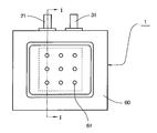
- FIG. 1 and FIG. 2 schematically show an air battery having a sheet-shaped exterior body made of a resin film as an example of the air battery of the present invention.
- 1 is a plan view of the air battery
- FIG. 2 is a cross-sectional view taken along the line II of FIG.
- the positive electrode 20, the separator 40, the negative electrode 30, and the electrolytic solution are accommodated in a sheet-like outer package 60.
- the positive electrode 20 is connected to the positive electrode external terminal 21 in the battery 1 through a lead body.
- the negative electrode 30 is also connected to the negative electrode external terminal 31 in the battery 1 through a lead body. is doing.
- the dotted line in FIG. 1 represents the size of the catalyst layer related to the positive electrode 20 accommodated in the sheet-shaped outer package 60.
- the sheet-shaped outer package 60 is provided with a plurality of air holes 61 for taking air into the positive electrode on one side where the positive electrode 20 is disposed, and the air holes 61 are provided on the sheet-shaped outer package 60 side of the positive electrode 20.
- a water repellent film 50 is disposed to prevent leakage of the electrolyte from the battery.
- the positive electrode 20 has a catalyst layer. As described above, for example, the positive electrode 20 has a structure in which the catalyst layer is laminated with a current collector, but in FIG. 2, in order to avoid complicated drawing, Each layer of the positive electrode 20 is not shown separately.
- Examples of the resin film constituting the sheet-shaped outer package include nylon films (such as nylon 66 film) and polyester films (such as polyethylene terephthalate (PET) film).
- the thickness of the resin film is preferably 20 to 100 ⁇ m.
- the sealing of the sheet-shaped exterior body is generally performed by heat-sealing the end portion of the upper resin film and the end portion of the lower resin film.
- a heat-sealing resin layer may be laminated on the resin film exemplified above and used for a sheet-shaped outer package.
- the heat fusion resin constituting the heat fusion resin layer include a modified polyolefin film (such as a modified polyolefin ionomer film), polypropylene, and a copolymer thereof.
- the thickness of the heat sealing resin layer is preferably 20 to 100 ⁇ m.
- a metal layer may be laminated on the resin film.
- the metal layer can be composed of an aluminum film (aluminum foil, including an aluminum alloy foil), a stainless steel film (stainless steel foil), or the like.
- the thickness of the metal layer is preferably 10 to 150 ⁇ m.
- the resin film constituting the sheet-shaped outer package may be a film having a structure in which the heat-sealing resin layer and the metal layer are laminated.
- the shape of the sheet-like exterior body may be a polygon (triangle, quadrangle, pentagon, hexagon, heptagon, octagon) in plan view, or may be circular or elliptical in plan view.
- the positive external terminal and the negative external terminal may be drawn out from the same side or may be drawn out from different sides.
- the water-repellent film for the air battery a film that has water repellency while allowing air to permeate is used.
- a fluorine resin such as PTFE
- a polyolefin such as polypropylene or polyethylene
- Film can be used.
- the thickness of the water repellent film is preferably 50 to 250 ⁇ m.
- an air diffusion film for supplying air taken into the exterior body to the positive electrode may be disposed between the exterior body and the water repellent film.
- a nonwoven fabric made of a resin such as cellulose, polyvinyl alcohol, polypropylene, or nylon can be used.
- the thickness of the air diffusion membrane is preferably 100 to 250 ⁇ m.
- polypropylene, nylon, etc. can be used as the gasket material interposed between the exterior can and the sealing plate, as well as heat resistance in relation to battery applications.
- a fluororesin such as tetrafluoroethylene-perfluoroalkoxyethylene copolymer (PFA), polyphenylene ether (PEE), polysulfone (PSF), polyarylate (PAR), polyethersulfone (PES). ), Polyphenylene sulfide (PPS), polyether ether ketone (PEEK), and the like
- PFA tetrafluoroethylene-perfluoroalkoxyethylene copolymer
- PEE polyphenylene ether
- PSF polysulfone
- PAR polyarylate
- PES polyethersulfone
- PES Polyphenylene sulfide
- PEEK polyether ether ketone
- the air battery of the present invention has a low environmental load, and even if the electrolyte leaked out due to damage or the like adheres to the body, it is less likely to cause a problem as compared with, for example, a strong alkaline electrolyte having a high pH. Therefore, the air battery of the present invention is a device that can be worn on the body, in particular, a device for medical / health use, such as a patch that is worn on the surface of the skin and measures the body condition such as body temperature, pulse, sweating amount, etc. It is suitable as a power source.
- Example 1 ⁇ Positive electrode> DBP oil absorption 495cm 3 / 100g, a specific surface area of 1270 m 2 / g of the carbon A (Ketjen Black EC600JD (Lion Specialty Chemicals Inc.)): and 75 parts by weight, PTFE: a 25 parts by weight, and water were mixed, Roll rolling was performed to form a sheet for the catalyst layer.
- this sheet was pressed onto a current collector made of SUS304 and made of a 700 mesh metal net (wire diameter: 0.1 mm, thickness: 0.25 mm) and dried, and the size of the catalyst layer was 30 mm ⁇ The thickness was 30 mm, and it was punched into a shape having an exposed portion of the current collector at one end. Further, a nickel lead wire was welded to the exposed portion of the current collector to form a lead portion, and a positive electrode (air electrode) having a total thickness of 300 ⁇ m was produced.
- the perchlorate ion content and the heavy metal ion content excluding iron ions contained in this electrolytic solution were each less than 100 ppm, and the content of the deleterious substances-designated compound was less than 10 ppm.
- ⁇ Separator> For the separator, two graft films (thickness: 15 ⁇ m) made of a graft copolymer having a structure in which acrylic acid is graft-copolymerized to a polyethylene main chain, a cellophane film (thickness: 20 ⁇ m) A laminate of vinylon-rayon mixed paper (thickness: 300 ⁇ m) was used.
- a PTFE sheet having a thickness of 200 ⁇ m was used for the water repellent film.
- ⁇ Battery assembly> Two aluminum laminate films (thickness: 65 ⁇ m) having a size of 5 cm ⁇ 5 cm having a PET film on the outer surface of the aluminum foil and a polypropylene film as a heat-sealing resin layer on the inner surface were used as an exterior body.
- the outer casing disposed on the positive electrode side has nine air holes of 1 mm in diameter of 9 mm in length and 9 mm in width so as to have the same arrangement as that shown in FIG. 1 with respect to the catalyst layer of the positive electrode.
- the water-repellent films were regularly formed at equal intervals (the distance between the centers of the air holes was 10 mm), and the water-repellent film was thermally welded to the inner surface side using a hot melt resin.
- the positive electrode, the separator, and the negative electrode are sequentially laminated on the water-repellent film of the outer package including the water-repellent film, and another outer package is further stacked.
- Three peripheral sides are thermally welded together to form a bag, and after pouring the electrolyte solution through the opening, the opening is thermally welded and sealed. did.
- heat-welding was performed after tape-like polypropylene was attached to the lead wires in advance.
- Example 2 In the formation of sheets of catalyst layer, in place of the carbon A (Ketjen Black), except for using DBP oil absorption of 131 cm 3/100 g, carbon B of a specific surface area of 140 m 2 / g and (furnace black) of Example 1 A sheet-like air battery was produced in the same manner as described above.
- Example 3 Carbon A (Ketjen Black): 50 parts by mass, manganese dioxide: 25 parts by mass, PTFE: 25 parts by mass and water were mixed, and roll-rolled to form a catalyst layer sheet. Thus, a sheet-like air battery was produced.
- Example 4 A sheet-like air battery was produced in the same manner as in Example 1 except that a PE microporous film (thickness: 30 ⁇ m, porosity: 50%) was used as the separator.
- Example 1 A sheet-like air battery was produced in the same manner as in Example 1 except that only vinylon-rayon mixed paper (thickness: 300 ⁇ m) was used as the separator.
- Comparative Example 3 A sheet-like air battery was produced in the same manner as in Comparative Example 2 except that only vinylon-rayon mixed paper (thickness: 300 ⁇ m) was used as the separator.
- the battery of Example 1 and the battery of Example 2 are compared, the battery of Example 1 using a carbon having a higher specific surface area and DBP oil absorption as the catalyst for the positive electrode is more effective than the battery of Example 2. Also showed excellent discharge capacity.
- a separator having a low air permeability (a high air permeability value) is provided. It can be seen that the use is effective in improving the discharge characteristics.
- Example 6 ⁇ Positive electrode> A positive electrode was produced using porous carbon paper [thickness: 0.25 mm, porosity: 75%, air permeability (Gurley): 70 seconds / 100 ml] as a current collector.
- ⁇ Negative electrode> The same zinc alloy foil as that of Example 1 was punched into a shape having a 15 mm ⁇ 15 mm portion serving as a main body of the negative electrode and a 5 mm ⁇ 15 mm portion serving as a lead portion at one end thereof to produce a negative electrode.
- the perchlorate ion content and the heavy metal ion content excluding iron ions contained in this electrolytic solution were each less than 100 ppm, and the content of the deleterious substances-designated compound was less than 10 ppm.
- ⁇ Separator> For the separator, two graft films (thickness: 15 ⁇ m) made of a graft copolymer having a structure in which acrylic acid is graft-copolymerized to a polyethylene main chain, a cellophane film (thickness: 20 ⁇ m) Used on both sides (total thickness: 50 ⁇ m).
- the air permeability of this separator was a value greater than 2000 sec / 100 ml.
- a PTFE sheet having a thickness of 200 ⁇ m was used for the water repellent film.
- ⁇ Battery assembly> Two aluminum laminate films (thickness: 65 ⁇ m) each having a size of 25 mm ⁇ 25 mm having a PET film on the outer surface of the aluminum foil and a polypropylene film as a heat-sealing resin layer on the inner surface were used as an outer package.
- Example 2 a sheet-like air battery having a thickness of 0.8 mm was produced in the same manner as in Example 1.
- nine air holes having a diameter of 0.5 mm were previously arranged at equal intervals of 9 mm in length ⁇ 9 mm in width (centers of air holes). The distance was 5 mm).
- the amount of the electrolyte solution injected into the exterior body was 0.1 ml.
- Example 7 A sheet-like air battery was produced in the same manner as in Example 6 except that the positive electrode current collector was changed to a 700 mesh metal mesh made of SUS304 (wire diameter: 0.1 mm, thickness: 0.25 mm).
- the open circuit voltage of the battery was measured using a digital multimeter manufactured by Hioki Electric Co., Ltd.
- discharge capacity measurement A constant resistance discharge at 3.9 k ⁇ was performed, and the discharge capacity when discharged to 0.5 V was measured. Moreover, the volume energy density was calculated
- Example 8 to 16 The electrolyte solution shown in Table 3 was prepared by changing the type and concentration of the salt serving as the electrolyte, and a sheet-like air battery was produced in the same manner as in Example 6 except that each electrolyte solution was used. Before assembling the batteries, the conductivity of each electrolyte was measured in a 25 ° C. environment using a “Personal SC Meter SC72” manufactured by Yokogawa Electric.
- Example 16 in all the electrolyte solutions, the content of perchlorate ions and the content of heavy metal ions excluding iron ions were each less than 100 ppm.
- the sheet-like air batteries of Examples 8 to 12 were allowed to stand in the atmosphere for 10 minutes after assembly, and then subjected to the above-mentioned “open circuit voltage measurement”, “discharge capacity measurement”, and “load characteristic evaluation”. In addition, the discharge capacity of the sheet-like air batteries of Examples 13 to 16 by constant resistance discharge at 3.9 k ⁇ was measured.
- the discharge capacity of the battery is increased and the load characteristics are also improved by setting the conductivity of the electrolyte to 80 mS / cm or more, particularly 150 mS / cm or more. I understand.
- the battery of Example 13 using iron (III) sulfate which is a salt of a strong acid and a weak base, shows a relatively large discharge capacity even though the electrolyte has a low conductivity of 40 mS / cm.
- the battery of Example 13 using an iron salt was used rather than the battery of Example 16 using zinc chloride not corresponding to any of ammonium salt, aluminum salt, magnesium salt and iron salt. Since the battery has a larger discharge capacity despite the low conductivity of the electrolyte, it can be seen that the battery characteristics can be further improved by using a specific salt as the electrolyte. .
- the air battery of the present invention is suitable as a power source for medical / health-use devices such as patches that can be worn on the body, and uses a conventionally known air battery. It can be applied to the same application.
- Air battery 20 Positive electrode (Air electrode) 21 Positive electrode external terminal 30 Negative electrode 31 Negative electrode external terminal 40 Separator 50 Water-repellent film 60 Sheet-like exterior body 61 Air hole
Landscapes
- Chemical & Material Sciences (AREA)
- Chemical Kinetics & Catalysis (AREA)
- Electrochemistry (AREA)
- General Chemical & Material Sciences (AREA)
- Engineering & Computer Science (AREA)
- Manufacturing & Machinery (AREA)
- Hybrid Cells (AREA)
- Sealing Battery Cases Or Jackets (AREA)
- Cell Electrode Carriers And Collectors (AREA)
- Cell Separators (AREA)
Abstract
環境負荷が小さく、良好な放電特性を有する空気電池と、前記空気電池を備えたパッチとを提供する。 本発明の空気電池は、触媒およびバインダーを含有する触媒層を有する正極、金属材料を含有する負極、セパレータおよび電解液が、外装体内に収容されてなり、前記電解液は、pHが3以上12未満の水溶液であり、前記セパレータは透気度が10sec/100ml以上であるか、または前記正極は集電体としてカーボン製の多孔性シートを有していることを特徴とするものである。本発明のパッチは、本発明の空気電池を電源として備えたことを特徴とするものである。
Description
本発明は、環境負荷が小さく、良好な放電特性を有する空気電池と、前記空気電池を備えたパッチに関するものである。
マンガン酸化物やカーボンなどを触媒とする空気極からなる正極と、亜鉛粒子や亜鉛合金粒子といった亜鉛系粒子などの金属材料を活物質とする負極とを有する空気電池は、近年になって、その適用を求める分野が広がってきており、それを受けて種々の改良が望まれている。
空気電池の改良点の一つに、環境負荷の低減が挙げられる。最近では、体温パッチなどのような身体用の各種センサや、ゴルフヘッド用の速度センサなどの電源として、空気電池を適用することが試みられているが、こうした用途では放電し切った空気電池の交換を一般のユーザー自身が行うことが通常であることから、使用を終えた空気電池も一般のユーザーが廃棄することが想定される。そのため、例えば、主にこうした用途に適用されるような空気電池には、特殊な手法などを経なくても、安全に、かつ環境に多大な影響を与えることなく廃棄できるように、環境負荷が小さいことが求められる。
現在の空気電池においては、例えば強アルカリ性である水酸化カリウム水溶液などのアルカリ金属の水酸化物の水溶液が電解液として汎用されている(特許文献1など)。他方、負極に使用する金属材料の種類によっては、よりpHが低い水溶液(塩化ナトリウム水溶液など)を空気電池の電解液として使用している例もあり(特許文献2など)、こうした手法によって空気電池の環境負荷の低減を図ることも考えられる。
ところが、塩化ナトリウム水溶液のようなpHの低い電解液を使用すると、強アルカリ性の電解液を使用した場合に比較して、空気電池の特性が著しく低下してしまい、実用レベルの特性を確保することが困難となってしまう。
本発明は、前記事情に鑑みてなされたものであり、その目的は、環境負荷が小さく、良好な放電特性を有する空気電池と、前記空気電池を備えたパッチとを提供することにある。
前記目的を達成し得た本発明の空気電池は、触媒およびバインダーを含有する触媒層を有する正極、金属材料を含有する負極、セパレータおよび電解液が、外装体内に収容されており、前記セパレータは、透気度が10sec/100ml以上であり、前記電解液は、pHが3以上12未満の水溶液であることを特徴とするものである。
また、本発明の空気電池の前記とは別の実施態様は、触媒およびバインダーを含有する触媒層を有する正極、金属材料を含有する負極、セパレータおよび電解液が、外装体内に収容されており、前記正極は、集電体としてカーボン製の多孔性シートを有し、前記電解液は、pHが3以上12未満の水溶液であることを特徴とするものである。
また、本発明のパッチは、身体に装着可能であって、本発明の空気電池を電源として備えたものである。
本発明によれば、環境負荷が小さく、良好な放電特性を有する空気電池と、前記空気電池を備えたパッチとを提供することができる。
前記の通り、pHが3以上12未満の水溶液を電解液として使用したときには、従来から汎用されている水酸化カリウム水溶液などの強アルカリ性(pHが14程度)の水溶液を電解液とした場合に比べて、空気電池の環境負荷を低減できる一方で、放電特性が著しく低下する。
ところが、pHが3以上12未満の電解液を含有する空気電池において、正極と負極との間に介在させるセパレータとして、透気度がある程度のレベルに制限されたもの、具体的には、透気度が10sec/100ml以上のものを用いた場合には、理由は定かではないが、放電容量および放電電圧を高めることができ、放電特性が大幅に向上することが、本発明者らの検討により明らかとなった。
なお、セパレータの透気度に対する放電特性の依存性は、強アルカリ性の電解液を有する空気電池では認められず、pHが一定以下の電解液を用いた空気電池に特有のものであると考えられる。
本発明の空気電池に用いるセパレータの透気度は、前記の通り10sec/100ml以上とすればよく、200sec/100ml以上であることが好ましく、400sec/100ml以上であることがより好ましく、1000sec/100ml以上であることが最も好ましい。なお、本発明の空気電池に用いるセパレータは、放電反応に必要となるイオンがセパレータを透過するイオン透過性のものであればよく、セパレータの透気度の上限値は、特に制限されない。
本明細書でいうセパレータの透気度、および後記のカーボンシートの透気度は、JIS P 8117に規定のガーレー法によって求められる値である。
前記の透気度を満たすセパレータとしては、樹脂製の多孔質膜(微多孔膜、不織布など)や、セロファンフィルムに代表される半透膜などの、空気電池などの各種電池で採用されているセパレータの中から、条件を満たすものを選択して用いることができる。
樹脂製の多孔質膜からなるセパレータを構成する樹脂としては、例えば、ポリエチレン(PE)、ポリプロピレン(PP)、エチレン-プロピレン共重合体などのポリオレフィンやポリエチレンテレフタレートなどのポリエステルなどが挙げられる。
樹脂製の多孔質膜からなるセパレータの場合、例えば、空孔率(空隙率)や空孔(空隙)の曲路率を調節することで、透気度を調整することができる。
樹脂製のセパレータの場合、空孔率は30~80%であることが好ましく、また、厚みは10~100μmであることが好ましい。
また、セロファンフィルムなどの半透膜は、電解液中の一部の成分のみを透過させることから、本発明において、放電特性の向上のために好ましく用いられる。半透膜をセパレータとして使用する場合、半透膜のみでセパレータを構成してもよい。しかしながら、半透膜は強度が小さいため、電池組み立て時の破損などの問題が発生しやすい。よって、特定の重合体で構成されるグラフトフィルムと、半透膜とを積層した積層体でセパレータを構成することも推奨される。
グラフトフィルムを構成するグラフト重合体は、例えば、幹ポリマーであるポリオレフィン(ポリエチレン、ポリプロピレンなど)に、(メタ)アクリル酸またはその誘導体が、グラフト重合した形態を有するものである。ただし、グラフト重合体は前記の形態を有していればよく、ポリオレフィンに、(メタ)アクリル酸やその誘導体をグラフト重合させる方法により製造されたものでなくともよい。
前記グラフト重合体を構成する(メタ)アクリル酸またはその誘導体とは、下記一般式(1)によって表されるものである。なお、下記一般式(1)のうち、R1はHまたはCH3であり、R2はHまたはNH4、Na、K、Rb、Csなどの親水性置換基を意味している。

前記のグラフトフィルムやセロファンフィルムは、これらのフィルムを構成する重合体自身が、電解液を吸収してイオンを透過する機能を有するものである。
前記グラフトフィルムを構成するグラフト重合体は、下記式(2)で定義されるグラフト率が、160%以上であることが好ましい。グラフト重合体のグラフト率とグラフトフィルムの電気抵抗には相関関係があるため、グラフト率が上記のような値のグラフト重合体を用いることで、グラフトフィルムの電気抵抗が、20~120mΩ・in2の好適値となるように制御することができる。なお、グラフトフィルムの電気抵抗は交流式電圧降下法(1kHz)により得られる値である。雰囲気温度を20~25℃とし、25±1℃の40%KOH(比重:1.400±0.005)水溶液中にフィルムを浸漬し、5~15時間後に取り出して、電気抵抗を測定すればよい。
グラフト率(%)=100×(A-B)/B (2)
前記式(2)中、A:グラフト重合体の質量(g)、B:グラフト重合体中の幹ポリマーの質量(g)である。なお、前記式(2)の「B(グラフト重合体中の幹ポリマーの質量)」は、例えば、グラフト重合体を、幹ポリマーであるポリオレフィンに、(メタ)アクリル酸やその誘導体をグラフト重合させる方法で形成する場合には、このグラフト重合に用いる幹ポリマーの質量を予め測定しておけばよい。また、前記グラフト重合体において、グラフト率が100%を超える場合があるのは、グラフト重合に用いるモノマー〔(メタ)アクリル酸やその誘導体〕同士が重合して、グラフト分子が長鎖となる場合があるからである。前記式(2)で定義されるグラフト重合体のグラフト率の上限値は、400%であることが好ましい。なお、前記の「(メタ)アクリル酸」とは、アクリル酸とメタクリル酸とを纏めて表現したものである。
セロファンフィルムのみで構成されるセパレータの場合、その厚みは、例えば、15μm以上であることが好ましく、また、40μm以下であることが好ましく、30μm以下であることがより好ましい。
更に、グラフトフィルムとセロファンフィルムとの積層体で構成されるセパレータの場合、グラフトフィルムとセロファンフィルムとの合計厚みで、例えば、30μm以上であることが好ましく、40μm以上であることがより好ましく、また、100μm以下であることが好ましく、70μm以下であることがより好ましく、60μm以下であることが最も好ましい。
更に、グラフトフィルムとセロファンフィルムの積層体で構成されるセパレータの場合、グラフトフィルムの厚みは、例えば、15μm以上であることが好ましく、25μm以上であることがより好ましく、また、50μm以下であることが好ましく、30μm以下であることがより好ましい。
セパレータを構成するためのグラフトフィルムとセロファンフィルムとの積層体としては、例えば、株式会社ユアサメンブレンシステムから「YG9132」や「YG9122」、「YG2152」の名称で市販されているものが挙げられる。
また、セロファンフィルムや、セロファンフィルムおよびグラフトフィルムと、ビニロン-レーヨン混抄紙のような吸液層(電解液保持層)とを組み合わせてセパレータを構成してもよい。このような吸液層の厚みは20~500μmであることが好ましい。
本発明の空気電池に係る電解液は、pHが、3以上、好ましくは3.5以上、より好ましくは4以上、特に好ましくは5以上であって、12未満、好ましくは10以下、より好ましくは8以下、特に好ましくは6.5以下の水溶液である。
電解液として使用する水溶液を構成するための電解質としては、塩化ナトリウム、塩化カリウム、塩化マグネシウム、塩化カルシウム、塩化アンモニウムや塩化亜鉛などの塩化物;アルカリ土類金属の水酸化物(水酸化マグネシウム、水酸化カルシウムなど)、酢酸塩(酢酸ナトリウム、酢酸カリウム、酢酸マグネシウムなど)、硝酸塩(硝酸ナトリウム、硝酸カリウム、硝酸マグネシウムなど)、硫酸塩(硫酸ナトリウム、硫酸カリウム、硫酸マグネシウムなど)、リン酸塩(リン酸ナトリウム、リン酸カリウム、リン酸マグネシウムなど)、ホウ酸塩(ホウ酸ナトリウム、ホウ酸カリウム、ホウ酸マグネシウムなど)、クエン酸塩(クエン酸ナトリウム、クエン酸カリウム、クエン酸マグネシウムなど)、グルタミン酸塩(グルタミン酸ナトリウム、グルタミン酸カリウム、グルタミン酸マグネシウムなど);アルカリ金属の炭酸水素塩(炭酸水素ナトリウム、炭酸水素カリウムなど);アルカリ金属の過炭酸塩(過炭酸ナトリウム、過炭酸カリウムなど);フッ化物などのハロゲンを含む化合物;多価カルボン酸;などが挙げられ、電解液は、これらの電解質のうちの1種または2種以上を含有していればよい。
なお、マンガン乾電池の電解液に用いられている塩化亜鉛などの水溶性亜鉛化合物や、空気電池の電解液に用いられている水酸化カリウムなどのアルカリ金属の水酸化物は、皮膚刺激性が強く、電解液が漏出して身体に付着すると、皮膚に炎症などのトラブルを生じる虞がある。このため、身体に密着させるなどして用いられる医療・健康機器の電源への適用を考慮した場合、皮膚への影響が小さい電解液構成とすることが望ましい。
上記の観点からは、電解液中にできるだけ水溶性の有害物質を含有させないことが望ましく、例えば、「劇物」に指定された化合物を含有させないことが望ましい。不純物として混入する場合の前記化合物は、通常、「劇物」とはみなされないが、そのような場合も考慮すると、「劇物」に指定された化合物の含有量は、0.5質量%以下であることが望ましく、0.1質量%以下であることがより望ましく、0.01質量%以下であることが特に望ましい。
なお、前記「劇物に指定された化合物」は、日本の「毒物及び劇物取締法」別表第二および「毒物及び劇物取締法施行令」第二条に規定されている化合物を指す。
一方、放電特性に優れた空気電池を構成するためには、電解質として、強酸と弱塩基とで形成される塩を用いることが好ましい。前記強酸としては、塩酸、硫酸、硝酸および過塩素酸などが例示され、前記弱塩基としては、水酸化アルミニウム、水酸化マグネシウムなど、アルカリ金属以外の金属元素の水酸化物や、アンモニアなどが例示される。
強酸と弱塩基との塩のうち、皮膚への影響が小さく、また廃棄する際の環境負荷を低減できることから、Cl-、SO4
2-、HSO4
-およびNO3
-より選択される少なくとも1種のイオンと、Alイオン、Mgイオン、Feイオンおよびアンモニウムイオンより選択される少なくとも1種のイオンとの塩が好ましく用いられる。前記の塩として、具体的には、硫酸アンモニウム、硫酸水素アンモニウム〔(NH4)HSO4〕、塩化アンモニウム、硝酸アンモニウムなどのアンモニウム塩;硫酸アルミニウム、塩化アルミニウム、硝酸アルミニウムなどのアルミニウム塩;硫酸マグネシウム、塩化マグネシウム、塩化水酸化マグネシウム〔MgCl(OH)〕、硝酸マグネシウムなどのマグネシウム塩;硫酸鉄(II)、硫酸アンモニウム鉄(II)〔(NH4)2Fe(SO4)2〕、硫酸鉄(III)、塩化鉄(II)、硝酸鉄(II)などの鉄塩;が例示される。これらの電解質は、電解液中に2種以上含有していてもよい。
強酸と弱塩基との塩を含有する水溶液は、塩化ナトリウムなどの強酸と強塩基との塩を含有する水溶液に比べて、負極活物質となる亜鉛や亜鉛合金などの金属材料を腐食させる作用が比較的小さい。また、強酸の塩のうち、Al、MgおよびFeより選択される金属元素の塩またはアンモニウム塩を含有する水溶液は、例えば塩化亜鉛水溶液に比べて比較的高い導電率を有している。このため、強酸と弱塩基との塩として、Cl-、SO4
2-、HSO4
-およびNO3
-より選択される少なくとも1種のイオンと、Alイオン、Mgイオン、Feイオンおよびアンモニウムイオンより選択される少なくとも1種のイオンとの塩を含有する水溶液を電解液として用いることにより、良好な放電特性を確保するとともに、その特性を長期間維持することも可能となる。
なお、Cl-イオンとFe3+イオンとの塩〔塩化鉄(III)〕については、その他のイオンの組み合わせによる塩に比べて負極活物質である金属材料を腐食させる作用が強いため、Cl-イオンとFeイオンとの塩としては、塩化鉄(II)〔FeCl2〕を用いることが好ましい。また、負極活物質である金属材料を腐食させる作用がより低いことから、弱塩基との塩としては、アンモニウム塩を用いることがより好ましい。
また、強酸の塩のうち、過塩素酸塩は、加熱や衝撃により燃焼や爆発の危険を生じやすいことから、環境負荷の低減や廃棄時の安全性確保の観点からは、電解質には過塩素酸塩以外の塩を用いることが好ましく、電解液が過塩素酸イオンを含む場合には、その含有量は、100ppm未満であることが好ましく、10ppm未満であることがより好ましい。
更に、前記強酸と弱塩基との塩のうち、塩化亜鉛や硫酸銅などに代表される重金属塩(ただし、鉄の塩を除く)は、有害物であるものが多いため、環境負荷や廃棄時の安全性の観点からは、電解液中での鉄イオンを除く重金属イオンの含有量も、100ppm未満であることが好ましく、10ppm未満であることがより好ましい。
良好な放電特性を確保するために、電解液の導電率を80mS/cm以上とすることが好ましく、150mS/cm以上とすることがより好ましく、200mS/cm以上とすることが特に好ましい。電解液中での電解質の濃度(1種のみを用いる場合は、その濃度であり、2種以上を用いる場合は、それらの濃度の合計)は、前記の導電率を確保できる範囲とすることが望ましい。電解液中での電解質の濃度は、通常、5~50質量%程度であり、電解液の導電率は、通常、700mS/cm程度まで高めることができる。ここでいう電解液の導電率は、後記の実施例で採用した方法で測定される値である。
なお、電解液における電解質の濃度を高くした場合には、電解液中で腐食反応(酸化反応)に関わる溶存酸素の濃度が減少し、低濃度の電解液を用いる場合よりも、負極活物質となる金属材料や、正極または負極の集電体の腐食反応が抑制されることが期待できる。例えば塩化ナトリウム水溶液の場合、濃度が3質量%(約0.5mol/l)で金属を腐食させる作用が最大となるが、電解質の濃度をこれより高めると電解液中の溶存酸素濃度が減少し、金属の酸化反応の進行が抑制される。
また、電解液中での電解質の濃度を高くすると、凝固点降下の作用により電解液が凝固する温度がより低下するため、低温での放電特性の向上が期待できる。
前記の観点から、電解液中での電解質の濃度(電解質を複数種使用する場合には、それらの濃度の合計。以下、同じ。)は、1mol/l以上であることが好ましく、2mol/l以上であることがより好ましく、3mol/l以上であることが特に好ましい。一方、電解質の種類にもよるが、電解液中での電解質の濃度が飽和濃度に近づくと、却ってイオン伝導度(導電率)が低下する場合も多いため、電解液中での電解質の濃度は、20℃での飽和濃度の90%以下とすることが好ましく、例えば、7mol/l以下であることが好ましく、5mol/l以下であることがより好ましい。
電解液には、インジウム化合物またはスズ化合物が溶解していることが好ましい。電解液中にインジウム化合物またはスズ化合物が溶解している場合には、電池内での水素ガスの発生をより良好に抑制することができる。
電解液に溶解させるインジウム化合物およびスズ化合物としては、水酸化物、酸化物、硫酸塩、硫化物、硝酸塩、臭化物、塩化物などが挙げられる。
前記化合物の電解液中の濃度は、質量基準で、0.005%以上であることが好ましく、0.01%以上であることがより好ましく、0.05%以上であることが特に好ましく、また、1%以下であることが好ましく、0.5%以下であることがより好ましく、0.1%以下であることが特に好ましい。
電解液には、前記の各成分の他に、本発明の効果を損なわない範囲で、必要に応じて公知の各種添加剤を添加してもよい。例えば、負極に用いる金属材料の腐食(酸化)を防止するために、酸化亜鉛を添加するなどしてもよい。なお、酸化亜鉛は、負極に添加することもできる。
また、電解液は、液状でもよいが、ゲル化剤を用いて、いわゆるゲル状としたものであってもよい。ゲル状の電解液を用いた場合には、負極活物質の腐食抑制効果がより向上する。
例えば、負極には、負極活物質となる金属や合金の箔をそのまま使用することができるが、この場合、電解液による腐食によって箔が切れるなどして負極の導電性が損なわれ、負極が有する容量を十分に引き出し得ないことがある。このような負極を用いた場合でも、前記の電解質濃度を有する電解液の使用によって、負極である箔の破断などを抑制できるが、ゲル状の電解質を用いた場合には、その抑制効果がより向上するため、電池容量の低下をより良好に抑えることができる。
電解液に使用可能なゲル化剤としては、例えば、ポリアクリル酸類(ポリアクリル酸、ポリアクリル酸ソーダ、ポリアクリル酸アンモニウムなど)、セルロース類(カルボキシメチルセルロース、メチルセルロース、ヒドロキシプロピルセルロースや、それらのアルカリ塩など)が挙げられる。また、特開2001-307746号公報に開示されているように、架橋ポリアクリル酸またはその塩類型吸水性ポリマー(例えば、ポリアクリル酸ソーダ、ポリアクリル酸アンモニウムなど)と、それら以外のゲル化剤とを併用することも好ましい。架橋ポリアクリル酸またはその塩類型吸水性ポリマーと併用するゲル化剤としては、前述のセルロース類や、架橋分枝型ポリアクリル酸またはその塩類(例えば、ソーダ塩、アンモニウム塩など)などが挙げられる。これらのゲル化剤は、1種のみを用いてもよく、2種以上を併用してもよい。
これらのゲル化剤の中でも、エーテル化度が1.0~1.5のカルボキシメチルセルロース(CMC)が好ましい。前記エーテル化度は、無水グルコース単位1個について、何個のカルボキシメチル基がエーテル結合しているかを表す数値である。前記エーテル化度を有するCMCは電解液を増粘させる作用が高いため、これを使用することで、より良好な性状のゲル状電解液を容易に調製できるようになる。
電解液におけるゲル化剤の含有量は、電解液を良好にゲル状にできる量であれば特に限定はされないが、通常、0.1~5質量%程度が好適である。
空気電池の正極(空気極)は、触媒層を有するものであり、例えば、触媒層と集電体とを積層した構造のものを使用することができる。
触媒層には、触媒やバインダーなどを含有させることができる。
触媒層に係る触媒としては、例えば、銀、白金族金属またはその合金、遷移金属、Pt/IrO2などの白金/金属酸化物、La1-xCaxCoO3などのペロブスカイト酸化物、WCなどの炭化物、Mn4Nなどの窒化物、二酸化マンガンなどのマンガン酸化物、カーボン〔黒鉛、カーボンブラック(アセチレンブラック、ケッチェンブラック、チャンネルブラック、ファーネスブラック、ランプブラック、サーマルブラックなど)、木炭、活性炭など〕などが挙げられ、これらのうちの1種または2種以上が使用される。
なお、触媒層は、電解液の成分を除き、重金属の含有量が1質量%以下であることが好ましい。このような触媒層を有する正極を用いることで、廃棄する際の環境負荷がより小さい空気電池とすることができる。
本明細書でいう触媒層中の重金属の含有量は、蛍光X線分析により測定することができる。例えば、リガク社製「ZSX100e」を用い、励起源:Rh50kV、分析面積:φ10mmの条件で測定することができる。
よって、触媒層に係る触媒には、重金属を含有していないものが推奨され、前記の各種カーボンを使用することがより好ましい。
また、正極の反応性をより高める観点からは、触媒として使用するカーボンの比表面積は、200m2/g以上であることが好ましく、300m2/g以上であることがより好ましく、500m2/g以上であることが更に好ましい。本明細書でいうカーボンの比表面積は、JIS K 6217に準じた、BET法によって求められる値であり、例えば、窒素吸着法による比表面積測定装置(Mountech社製「Macsorb HM modele-1201」)を用いて測定することができる。なお、カーボンの比表面積の上限値は、通常、2000m2/g程度である。
更に、正極の導電性を確保する観点から、触媒として使用するカーボンのDBP吸油量は150cm3/100g以上であることが好ましく、200cm3/100g以上であることがより好ましく、300cm3/100g以上であることが更に好ましい。本明細書でいうカーボンのDBP吸油量は、JIS K 6217に準じて測定することができる(後記の実施例に記載の値は、この方法で求めた値である)。
一方、DBP吸収量が大きいと、ストラクチャーが発達してカーボン内の空間が大きくなり、必要とする電解液が多くなるため、触媒として使用するカーボンのDBP吸油量は1000cm3/100g以下であることが好ましく、800cm3/100g以下であることがより好ましく、600cm3/100g以下であることが更に好ましい。
触媒層における触媒の含有量は、20~70質量%であることが好ましい。
触媒層に係るバインダーとしては、フッ化ビニリデンの重合体〔ポリフッ化ビニリデン(PVDF)〕、テトラフルオロエチレンの重合体〔ポリテトラフルオロエチレン(PTFE)〕、フッ化ビニリデンの共重合体やテトラフルオロエチレンの共重合体〔フッ化ビニリデン-ヘキサフルオロプロピレン共重合体(PVDF-HFP)、フッ化ビニリデン-クロロトリフルオロエチレン共重合体(PVDF-CTFE)、フッ化ビニリデン-テトラフルオロエチレン共重合体(PVDF-TFE)、フッ化ビニリデン-ヘキサフルオロプロピレン-テトラフルオロエチレン共重合体(PVDF-HFP-TFE)など〕などのフッ素樹脂バインダーなどが挙げられる。これらの中でも、テトラフルオロエチレンの重合体または共重合体が好ましく、PTFEがより好ましい。触媒層におけるバインダーの含有量は、3~50質量%であることが好ましい。
正極における触媒層の厚みは、50~500μmであることが好ましい。
正極に係る集電体には、例えば、チタン、ニッケル、ステンレス、銅などの金属材料で構成された網、箔、エキスパンドメタル、パンチングメタル;カーボンペーパー、カーボンクロス、カーボンフェルトなどのカーボンシート(繊維状カーボンで構成されたカーボンシート)などといったカーボン製の多孔性シート;などを用いることができる。
なお、本発明者らの検討によれば、pHが3以上12未満の水溶液を電解液として使用したときには、前記のセパレータに起因する放電特性の低下とは別に、正極の集電体の材質によっても、放電特性の低下が生じ得ることが明らかとなった。
すなわち、空気電池における正極の集電体としては、ステンレスなどの金属材料で構成された網などが一般に用いられており、水酸化カリウム水溶液などの強アルカリ性(pHが14程度)の水溶液を電解液とする場合には、集電体として支障なく機能させることができる。
ところが、前記強アルカリ性の水溶液よりもpHが低い水溶液を電解液とする場合には、金属製の正極集電体が腐食しやすくなり、放電電流が大きくなった場合などに放電特性の低下を生じやすくなる。
そのため、pHが3以上12未満の水溶液を電解液とする場合には、正極の集電体としては、前記腐食の問題を生じないカーボン製の集電体(多孔性シートなど)を用いることが望ましく、これにより正極の集電体に起因する放電特性の低下を抑制することが可能となる。
前記カーボンシートは、単層構造であってもよく、カーボンペーパー同士、カーボンクロス同士、カーボンフェルト同士が積層された多層構造であってもよく、カーボンペーパー、カーボンクロスおよびカーボンフェルトのうちの2種以上が積層された多層構造であってもよい。
また、前記カーボンシートは、カーボン以外の素材で構成された基体と一体化され、全体が多孔性の集電体を構成していてもよい。
カーボンシートの透気度(厚さ方向)を表すガーレー値は、空孔率が大きくなり過ぎ導電性が低下するのを防ぐため、1sec/100ml以上であることが好ましく、5sec/100ml以上であることがより好ましい。一方、空孔率を一定以上にして空気の透過を妨げないようにするために、カーボンシートのガーレー値は500sec/100ml以下であることが好ましく、200sec/100ml以下であることがより好ましい。
また、カーボンシートを構成する繊維状カーボンの繊維径は、通常、2~30μm程度とすればよい。
正極に係る集電体の厚みは、10~500μmであることが好ましく、取扱い性や入手の容易さ、正極での十分な集電機能の確保などの点から、30μm以上とすることが好ましく、50μm以上とすることがより好ましい。
前記カーボンシートの空孔率は、良好な透気性と十分な強度とを確保する観点から、50%以上95%以下であることが好ましく、市販品の中から、適切なものを選択して使用すればよい。
触媒層は、例えば、前記触媒、バインダーなどを水と混合してロールで圧延し、集電体と密着させることにより製造することができる。また前記の触媒や必要に応じて使用するバインダーなどを、水や有機溶媒に分散させて調製した触媒層形成用組成物(スラリー、ペーストなど)を、集電体の表面に塗布し乾燥した後に、必要に応じてカレンダ処理などのプレス処理を施す工程を経て製造することもできる。
空気電池の負極には、亜鉛系材料(亜鉛材料と亜鉛合金材料とを纏めてこのように称する)やマグネシウム系材料(マグネシウム材料とマグネシウム合金材料とを纏めてこのように称する)やアルミニウム系材料(アルミニウム材料とアルミニウム合金材料とを纏めてこのように称する)などの金属材料を含有するものが使用される。このような負極では、亜鉛やマグネシウムやアルミニウムといった金属が、活物質として作用する。
なお、空気電池の更なる環境負荷低減の観点からは、負極に使用する金属材料は、水銀、カドミウム、鉛およびクロムの含有量が少ないことが好ましく、具体的な含有量が、質量基準で、水銀:0.1%ppm以下、カドミウム:0.01%ppm以下、鉛:0.1%ppm以下、およびクロム:0.1%ppm以下であることがより好ましい。
より具体的には、例えば、亜鉛系粒子(亜鉛粒子と亜鉛合金粒子とを纏めてこのように称する)やマグネシウム系粒子(マグネシウム粒子とマグネシウム合金粒子とを纏めてこのように称する)やアルミニウム系粒子(アルミニウム粒子とアルミニウム合金粒子とを纏めてこのように称する)などを含有する負極を使用することができる。亜鉛合金粒子の合金成分としては、例えば、インジウム(例えば含有量が質量基準で0.005~0.05%)、ビスマス(例えば含有量が質量基準で0.005~0.05%)、アルミニウム(例えば含有量が質量基準で0.001~0.15%)などが挙げられる。
また、マグネシウム合金粒子の合金成分としては、例えば、カルシウム(例えば含有量が質量基準で1~3%)、マンガン(例えば含有量が質量基準で0.1~0.5%)、亜鉛(例えば含有量が質量基準で0.4~1%)、アルミニウム(例えば含有量が質量基準で8~10%)などが挙げられる。
更に、アルミニウム合金粒子の合金成分としては、例えば、亜鉛(例えば含有量が質量基準で0.5~10%)、スズ(例えば含有量が質量基準で0.04~1.0%)、ガリウム(例えば含有量が質量基準で0.003~1.0%)、ケイ素(例えば含有量が質量基準で0.05%以下)、鉄(例えば含有量が質量基準で0.1%以下)、マグネシウム(例えば含有量が質量基準で0.1~2.0%)、マンガン(例えば含有量が質量基準で0.01~0.5%)などが挙げられる。
金属粒子を含有する負極の場合、その金属粒子は、1種単独でもよく、2種以上であってもよい。
亜鉛系粒子の粒度としては、例えば、全粒子中、粒径が75μm以下の粒子の割合が50質量%以下のものが好ましく、30質量%以下のものがより好ましく、また、粒径が100~200μmの粒子の割合が、50質量%以上、より好ましくは90質量%以上であるものが挙げられる。
また、マグネシウム系粒子およびアルミニウム系粒子の粒度としては、例えば、全粒子中、粒径が30μm以下の粒子の割合が50質量%以下のものが好ましく、30質量%以下のものがより好ましく、また、粒径が50~200μmの粒子の割合が、50質量%以上、より好ましくは90質量%以上であるものが挙げられる。
本明細書でいう金属粒子における粒度は、レーザー散乱粒度分布計(例えば、堀場製作所製「LA-920」)を用い、粒子を溶解しない媒体に、これらの粒子を分散させて測定した、体積基準での累積頻度50%における粒径(D50)である。
前記の金属粒子を含有する負極の場合には、必要に応じて添加されるゲル化剤(ポリアクリル酸ソーダ、カルボキシメチルセルロースなど)やバインダーを含んでもよく、これに電解液を加えることで構成される負極剤(ゲル状負極など)を使用することができる。負極中のゲル化剤の量は、例えば、0.5~1.5質量%とすることが好ましく、バインダーの量は、0.5~3質量%とすることが好ましい。
金属粒子を含有する負極に係る電解液には、電池に注入するものと同じものを使用することができる。
負極における金属粒子の含有量は、例えば、60質量%以上であることが好ましく、65質量%以上であることがより好ましく、また、95質量%以下であることが好ましく、90質量%以下であることがより好ましい。
金属粒子を含有する負極は、インジウム化合物を含有していることが好ましい。負極がインジウム化合物を含有することによって、金属粒子と電解液との腐食反応による水素ガス発生をより効果的に防ぐことができる。
前記のインジウム化合物としては、例えば、酸化インジウム、水酸化インジウムなどが挙げられる。
負極に使用するインジウム化合物の量は、質量比で、金属粒子:100に対し、0.003~1であることが好ましい。
また、負極には、前記亜鉛系粒子と同じ組成の亜鉛系シート(亜鉛箔や亜鉛合金箔など)や、前記マグネシウム系粒子と同じ組成のマグネシウム系シート(マグネシウム箔やマグネシウム合金箔など)といった金属シートを用いることもできる。このような負極の場合、その厚みは、10~500μmであることが好ましい。
また、このような金属シートを有する負極の場合には、必要に応じて集電体を用いてもよい。負極の集電体としては、ニッケル、銅、ステンレスなどの金属製の網、箔、エキスパンドメタル、パンチングメタル;カーボンのシート、網;などが挙げられる。負極の集電体の厚みは、10~300μmであることが好ましい。
また、電池の形状がシート状である場合、その外装体(シート状外装体)の内面(負極と対向する面)にカーボンペーストを塗布することにより、負極の集電体とすることもできる。前記のカーボンペースト層の厚みは、50~200μmであることが好ましい。
更に、シート状外装体の内面に蒸着などにより金属層を形成し、これを負極の集電体としてもよい。
空気電池の形態については特に制限はなく、外装缶と封口板とをガスケットを介してカシメ封口したり、外装缶と封口板とを溶接して封口したりする電池ケースを有する扁平形(コイン形、ボタン形を含む);樹脂フィルム製のシート状外装体を有するシート形;有底筒形の外装缶と封口板とをガスケットを介してカシメ封口したり、外装缶と封口板とを溶接して封口したりする電池ケースを有する筒形〔円筒形、角形(角筒形)〕;など、いずれの形態とすることもできる。
特に前記のシート形の形態とした場合には、電池を薄型化することができるため、外装缶を有する形態では使用し難い用途への適用が可能となるほか、外装缶を有する形態のものに比べて廃棄も容易になることから、ディスポーザブル機器の電源として好適な電池を構成することができる。
また、シート状外装体の内面が樹脂層である場合には、電解液による外装体の腐食の問題を防ぐことができる。
図1および図2に本発明の空気電池の一例として、樹脂フィルム製のシート状外装体を有する空気電池を模式的に示している。図1は空気電池の平面図であり、図2は図1のI-I線断面図である。
図2に示すように、空気電池1は、正極20、セパレータ40および負極30と、電解液(図示しない)とが、シート状外装体60内に収容されている。正極20は、電池1内でリード体を介して正極外部端子21と接続しており、また、図示していないが、負極30も、電池1内でリード体を介して負極外部端子31と接続している。なお、図1における点線は、シート状外装体60内に収容された正極20に係る触媒層の大きさを表している。
シート状外装体60は、正極20が配置された側の片面に、正極に空気を取り込むための空気孔61が複数設けられており、正極20のシート状外装体60側には、空気孔61からの電解液の漏出を防止するための撥水膜50が配置されている。
正極20は、触媒層を有しており、前記の通り、例えば触媒層が集電体と積層された構造を有しているが、図2では、図面が煩雑になることを避けるために、正極20の有する各層を区別して示していない。
シート状外装体を構成する樹脂フィルムとしては、ナイロンフィルム(ナイロン66フィルムなど)、ポリエステルフィルム〔ポリエチレンテレフタレート(PET)フィルムなど〕などが挙げられる。樹脂フィルムの厚みは、20~100μmであることが好ましい。
なお、シート状外装体の封止は、シート状外装体の上側の樹脂フィルムの端部と下側の樹脂フィルムの端部との熱融着によって行うことが一般的であるが、この熱融着をより容易にする目的で、前記例示の樹脂フィルムに熱融着樹脂層を積層してシート状外装体に用いてもよい。熱融着樹脂層を構成する熱融着樹脂としては、変性ポリオレフィンフィルム(変性ポリオレフィンアイオノマーフィルムなど)、ポリプロピレンおよびその共重合体などが挙げられる。熱融着樹脂層の厚みが20~100μmであることが好ましい。
また、樹脂フィルムには金属層を積層してもよい。金属層は、アルミニウムフィルム(アルミニウム箔。アルミニウム合金箔を含む。)、ステンレス鋼フィルム(ステンレス鋼箔。)などにより構成することができる。金属層の厚みが10~150μmであることが好ましい。
また、シート状外装体を構成する樹脂フィルムは、前記の熱融着樹脂層と前記の金属層とが積層された構成のフィルムであってもよい。
シート状外装体の形状は、平面視で多角形(三角形、四角形、五角形、六角形、七角形、八角形)であってもよく、平面視で円形や楕円形であってもよい。なお、平面視で多角形のシート状外装体の場合、正極外部端子および負極外部端子は、同一辺から外部へ引き出してもよく、それぞれを異なる辺から外部へ引き出しても構わない。
空気電池に係る撥水膜には、撥水性がある一方で空気を透過できる膜が使用され、具体的には、例えば、PTFEなどのフッ素樹脂;ポリプロピレン、ポリエチレンなどのポリオレフィン;などの樹脂で構成された膜を用いることができる。撥水膜の厚みは、50~250μmであることが好ましい。
空気電池には、外装体と撥水膜との間に、外装体内に取り込んだ空気を正極に供給するための空気拡散膜を配置してもよい。空気拡散膜には、セルロース、ポリビニルアルコール、ポリプロピレン、ナイロンなどの樹脂で構成された不織布を用いることができる。空気拡散膜の厚みは、100~250μmであることが好ましい。
また、カシメ封口を行う形態の外装体を使用する場合、外装缶と封口板との間に介在させるガスケットの素材には、ポリプロピレン、ナイロンなどを使用できるほか、電池の用途との関係で耐熱性が要求される場合には、テトラフルオロエチレン-パーフルオロアルコキシエチレン共重合体(PFA)などのフッ素樹脂、ポリフェニレンエーテル(PEE)、ポリスルフォン(PSF)、ポリアリレート(PAR)、ポリエーテルスルフォン(PES)、ポリフェニレンサルファイド(PPS)、ポリエーテルエーテルケトン(PEEK)などの融点が240℃を超える耐熱樹脂を使用することもできる。また、電池が耐熱性を要求される用途に適用される場合、その封口には、ガラスハーメチックシールを利用することもできる。
本発明の空気電池は、環境負荷が小さく、また、破損などによって漏出した電解液が身体に付着しても、例えばpHが高い強アルカリ性の電解液に比べて問題が生じ難い。よって、本発明の空気電池は、身体に装着可能なパッチ、特に、皮膚の表面に装着し、体温、脈拍、発汗量など身体の状況に関する測定を行うためのパッチなど、医療・健康用途の機器の電源として好適である。
以下、実施例に基づいて本発明を詳細に述べる。ただし、下記実施例は、本発明を制限するものではない。
(実施例1)
<正極>
DBP吸油量495cm3/100g、比表面積1270m2/gのカーボンA(ケッチェンブラックEC600JD(ライオン・スペシャリティ・ケミカルズ社)):75質量部と、PTFE:25質量部と、水とを混合し、ロール圧延して触媒層用のシートを形成した。次に、このシートを、SUS304製で700メッシュの金属網(線径:0.1mm、厚み:0.25mm)よりなる集電体に圧着させてから乾燥し、触媒層の大きさが30mm×30mmとなり、一端に集電体の露出部を有する形状に打ち抜いた。更に、前記集電体の露出部にニッケルのリード線を溶接してリード部とし、全体の厚みが300μmの正極(空気極)を作製した。
<正極>
DBP吸油量495cm3/100g、比表面積1270m2/gのカーボンA(ケッチェンブラックEC600JD(ライオン・スペシャリティ・ケミカルズ社)):75質量部と、PTFE:25質量部と、水とを混合し、ロール圧延して触媒層用のシートを形成した。次に、このシートを、SUS304製で700メッシュの金属網(線径:0.1mm、厚み:0.25mm)よりなる集電体に圧着させてから乾燥し、触媒層の大きさが30mm×30mmとなり、一端に集電体の露出部を有する形状に打ち抜いた。更に、前記集電体の露出部にニッケルのリード線を溶接してリード部とし、全体の厚みが300μmの正極(空気極)を作製した。
<負極>
添加元素としてIn:0.05%、Bi:0.04%およびAl:0.001%含有する亜鉛合金箔(厚み:0.05mm)を、負極の本体となる30mm×30mmの部分と、その一端に負極のリード部となる5mm×15mmの部分とを有する形状に打ち抜いて、負極を作製した。
添加元素としてIn:0.05%、Bi:0.04%およびAl:0.001%含有する亜鉛合金箔(厚み:0.05mm)を、負極の本体となる30mm×30mmの部分と、その一端に負極のリード部となる5mm×15mmの部分とを有する形状に打ち抜いて、負極を作製した。
<電解液>
電解液には、20質量%の塩化ナトリウム水溶液(pH=7)を用いた。この電解液に含まれる過塩素酸イオンの含有量、および、鉄イオンを除く重金属イオンの含有量は、それぞれ100ppm未満であり、劇物指定の化合物の含有量は、10ppm未満であった。
電解液には、20質量%の塩化ナトリウム水溶液(pH=7)を用いた。この電解液に含まれる過塩素酸イオンの含有量、および、鉄イオンを除く重金属イオンの含有量は、それぞれ100ppm未満であり、劇物指定の化合物の含有量は、10ppm未満であった。
<セパレータ>
セパレータには、ポリエチレン主鎖にアクリル酸をグラフト共重合させた構造を有するグラフト共重合体で構成された2枚のグラフトフィルム(1枚当たりの厚み:15μm)を、セロハンフィルム(厚み:20μm)の両側に配置し、更にビニロン-レーヨン混抄紙(厚み:300μm)を積層したものを用いた。
セパレータには、ポリエチレン主鎖にアクリル酸をグラフト共重合させた構造を有するグラフト共重合体で構成された2枚のグラフトフィルム(1枚当たりの厚み:15μm)を、セロハンフィルム(厚み:20μm)の両側に配置し、更にビニロン-レーヨン混抄紙(厚み:300μm)を積層したものを用いた。
<撥水膜>
撥水膜には、厚みが200μmのPTFE製シートを用いた。
撥水膜には、厚みが200μmのPTFE製シートを用いた。
<電池の組み立て>
アルミニウム箔の外面にPETフィルムを有し、内面に熱融着樹脂層としてポリプロピレンフィルムを有する5cm×5cmの大きさのアルミラミネートフィルム(厚み:65μm)を2枚用いて外装体とした。
アルミニウム箔の外面にPETフィルムを有し、内面に熱融着樹脂層としてポリプロピレンフィルムを有する5cm×5cmの大きさのアルミラミネートフィルム(厚み:65μm)を2枚用いて外装体とした。
前記外装体のうち正極側に配置する外装体には、正極の触媒層に対して図1で示すものと同様の配置になるように、直径1mmの空気孔9個を縦9mm×横9mmの等間隔(空気孔同士の中心間距離は10mm)で規則的に形成し、その内面側に、ホットメルト樹脂を用いて前記撥水膜を熱溶着させた。
次に、前記撥水膜を備えた前記外装体の撥水膜の上に、前記正極、前記セパレータおよび前記負極を順に積層し、更にもう1枚の外装体を重ね、2枚の外装体の周囲3辺(リード線を取り出す辺以外)を互いに熱溶着して袋状にし、その開口部から前記電解液を注入した後、前記開口部を熱溶着して封止し、シート状空気電池とした。
なお、正極および負極のリード線と外装体との熱溶着部の封止性を高めるため、あらかじめ前記リード線にテープ状のポリプロピレンを取り付けた後に熱溶着を行った。
(実施例2)
触媒層用のシートの形成において、カーボンA(ケッチェンブラック)に代えて、DBP吸油量131cm3/100g、比表面積140m2/gのカーボンB(ファーネスブラック)を用いた以外は、実施例1と同様にしてシート状空気電池を作製した。
触媒層用のシートの形成において、カーボンA(ケッチェンブラック)に代えて、DBP吸油量131cm3/100g、比表面積140m2/gのカーボンB(ファーネスブラック)を用いた以外は、実施例1と同様にしてシート状空気電池を作製した。
(実施例3)
カーボンA(ケッチェンブラック):50質量部、二酸化マンガン:25質量部、PTFE:25質量部および水を混合し、ロール圧延して触媒層用のシートを形成した以外は、実施例1と同様にしてシート状空気電池を作製した。
カーボンA(ケッチェンブラック):50質量部、二酸化マンガン:25質量部、PTFE:25質量部および水を混合し、ロール圧延して触媒層用のシートを形成した以外は、実施例1と同様にしてシート状空気電池を作製した。
(実施例4)
セパレータとして、PE製の微多孔フィルム(厚み:30μm、空孔率:50%)を用いた以外は、実施例1と同様にしてシート状空気電池を作製した。
セパレータとして、PE製の微多孔フィルム(厚み:30μm、空孔率:50%)を用いた以外は、実施例1と同様にしてシート状空気電池を作製した。
(実施例5)
電解液として、20質量%の硫酸マグネシウム水溶液(pH=5)を用いた以外は、実施例1と同様にしてシート状空気電池を作製した。
電解液として、20質量%の硫酸マグネシウム水溶液(pH=5)を用いた以外は、実施例1と同様にしてシート状空気電池を作製した。
(比較例1)
セパレータとして、ビニロン-レーヨン混抄紙(厚み:300μm)のみを用いた以外は、実施例1と同様にしてシート状空気電池を作製した。
セパレータとして、ビニロン-レーヨン混抄紙(厚み:300μm)のみを用いた以外は、実施例1と同様にしてシート状空気電池を作製した。
(比較例2)
電解液として、30質量%の水酸化カリウム水溶液(pH=14)を用いた以外は、実施例1と同様にしてシート空気電池を作製した。
電解液として、30質量%の水酸化カリウム水溶液(pH=14)を用いた以外は、実施例1と同様にしてシート空気電池を作製した。
(比較例3)
セパレータとして、ビニロン-レーヨン混抄紙(厚み:300μm)のみを用いた以外は、比較例2と同様にしてシート状空気電池を作製した。
セパレータとして、ビニロン-レーヨン混抄紙(厚み:300μm)のみを用いた以外は、比較例2と同様にしてシート状空気電池を作製した。
実施例および比較例のシート状空気電池、並びに、これらの電池に用いた電解液および正極について、下記の評価を行った。これらの評価結果を、各電池の構成と併せて表1に示す。
〔電解液のpH測定〕
電解液のpHは、堀場製作所製の「LAQUA TwinコンパクトpHメータ」を用い、25℃環境下で測定した。
電解液のpHは、堀場製作所製の「LAQUA TwinコンパクトpHメータ」を用い、25℃環境下で測定した。
〔正極の触媒層における重金属量の測定〕
正極の触媒層における重金属量の測定は、蛍光X線分析により行った。各材料を混合後、ロール圧延して触媒層用のシートを形成した後、60℃24時間乾燥し、φ10mmに打ち抜き、測定用試料とした。そして各測定用試料について、リガク社製「ZSX100e」を用い、励起源:Rh50kV、分析面積:φ10mmの条件で重金属量を測定した。
正極の触媒層における重金属量の測定は、蛍光X線分析により行った。各材料を混合後、ロール圧延して触媒層用のシートを形成した後、60℃24時間乾燥し、φ10mmに打ち抜き、測定用試料とした。そして各測定用試料について、リガク社製「ZSX100e」を用い、励起源:Rh50kV、分析面積:φ10mmの条件で重金属量を測定した。
〔放電特性の評価〕
各シート状空気電池を組み立て後、大気中で10分間放置してから、電池の設計容量(負極の容量)に対して100時間率相当の電流で0.5Vまで放電した時の放電容量を測定した。各電池の測定値は、比較例2の電池の放電容量を1.0として相対比較した。
各シート状空気電池を組み立て後、大気中で10分間放置してから、電池の設計容量(負極の容量)に対して100時間率相当の電流で0.5Vまで放電した時の放電容量を測定した。各電池の測定値は、比較例2の電池の放電容量を1.0として相対比較した。
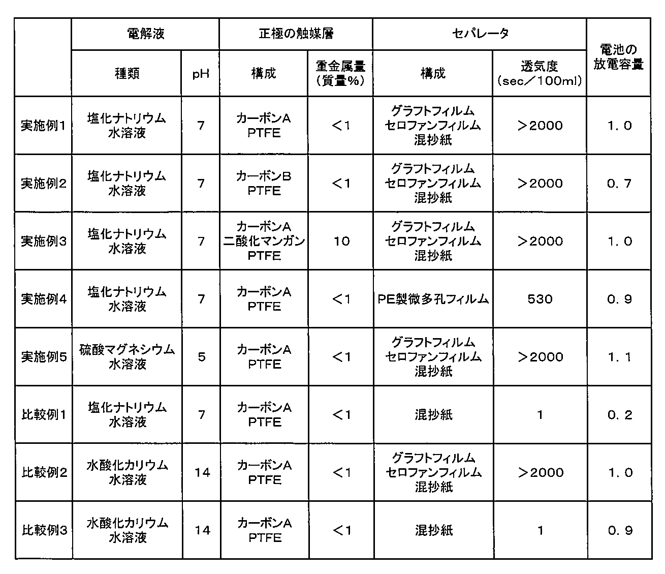
表1に示す通り、実施例1~5のシート状空気電池は、電解液にpH=6の塩化ナトリウム水溶液またはpH=5の硫酸マグネシウム水溶液を用いているにもかかわらず、透気度が10sec/100ml以上のセパレータを用いているため、pH=14の水酸化カリウム水溶液を電解液に用いた比較例3の電池と同様に、実用性の高い優れた放電容量を示した。なお、実施例1の電池と実施例2の電池とを比較すると、正極の触媒に比表面積およびDBP吸油量がより高いカーボンを使用した実施例1の電池の方が、実施例2の電池よりも優れた放電容量を示した。
また、比較例2および比較例3の電池の放電容量の比較より明らかなように、電解液にpH=14の水酸化カリウム水溶液を用いた空気電池では、セパレータの透気度の違いによる電池特性の差がほとんど認められなかったのに対し、電解液にpH=7の塩化ナトリウム水溶液を使用した実施例1、実施例4および比較例1の電池では、放電容量がセパレータの透気度に依存する結果が示された。
このことから、従来から空気電池に汎用されているものよりもpHが低い、pHが12未満の電解液を用いた空気電池において、透気性の低い(透気度が高い値である)セパレータを用いることが放電特性の向上に効果的であることがわかる。
(実施例6)
<正極>
集電体として、多孔性のカーボンペーパー〔厚み:0.25mm、空孔率:75%、透気度(ガーレー):70秒/100ml〕を用いて正極を作製した。
<正極>
集電体として、多孔性のカーボンペーパー〔厚み:0.25mm、空孔率:75%、透気度(ガーレー):70秒/100ml〕を用いて正極を作製した。
前記カーボンA:30質量部と、アクリル系分散剤:15質量部と、SBR:60質量部と、水:500質量部とを混合して触媒層形成用組成物を形成し、前記集電体の表面に、乾燥後の量が10mg/cm2となるように前記組成物をストライプ塗布して乾燥させた。そして、乾燥後のシートについて、触媒層の大きさが15mm×15mmで、一端にリード部となる集電体の露出部(サイズが5mm×15mm)を有する形状に打ち抜いて、全体の厚みが0.27mmの正極(空気極)を作製した。
<負極>
実施例1と同じ亜鉛合金箔を、負極の本体となる15mm×15mm部分と、その一端にリード部となる5mm×15mmの部分とを有する形状に打ち抜いて、負極を作製した。
実施例1と同じ亜鉛合金箔を、負極の本体となる15mm×15mm部分と、その一端にリード部となる5mm×15mmの部分とを有する形状に打ち抜いて、負極を作製した。
<電解液>
電解液には、3mol/lの濃度の塩化ナトリウム水溶液(pH=7)を用いた。この電解液に含まれる過塩素酸イオンの含有量、および、鉄イオンを除く重金属イオンの含有量は、それぞれ100ppm未満であり、劇物指定の化合物の含有量は、10ppm未満であった。
電解液には、3mol/lの濃度の塩化ナトリウム水溶液(pH=7)を用いた。この電解液に含まれる過塩素酸イオンの含有量、および、鉄イオンを除く重金属イオンの含有量は、それぞれ100ppm未満であり、劇物指定の化合物の含有量は、10ppm未満であった。
<セパレータ>
セパレータには、ポリエチレン主鎖にアクリル酸をグラフト共重合させた構造を有するグラフト共重合体で構成された2枚のグラフトフィルム(1枚当たりの厚み:15μm)を、セロハンフィルム(厚み:20μm)の両側に配置したもの(全体の厚み:50μm)を用いた。このセパレータの透気度は、2000sec/100mlよりも大きな値となった。
セパレータには、ポリエチレン主鎖にアクリル酸をグラフト共重合させた構造を有するグラフト共重合体で構成された2枚のグラフトフィルム(1枚当たりの厚み:15μm)を、セロハンフィルム(厚み:20μm)の両側に配置したもの(全体の厚み:50μm)を用いた。このセパレータの透気度は、2000sec/100mlよりも大きな値となった。
<撥水膜>
撥水膜には、厚みが200μmのPTFE製シートを用いた。
撥水膜には、厚みが200μmのPTFE製シートを用いた。
<電池の組み立て>
アルミニウム箔の外面にPETフィルムを有し、内面に熱融着樹脂層としてポリプロピレンフィルムを有する25mm×25mmの大きさのアルミラミネートフィルム(厚み:65μm)を2枚用いて外装体とした。
アルミニウム箔の外面にPETフィルムを有し、内面に熱融着樹脂層としてポリプロピレンフィルムを有する25mm×25mmの大きさのアルミラミネートフィルム(厚み:65μm)を2枚用いて外装体とした。
以下、実施例1と同様にして、厚さ0.8mmのシート状空気電池を作製した。なお、前記外装体のうち正極側に配置する外装体には、実施例1と同様にして、あらかじめ直径0.5mmの空気孔9個を縦9mm×横9mmの等間隔(空気孔同士の中心間距離は5mm)で規則的に形成しておいた。また、外装体内部に注液する電解液量は0.1mlとした。
(実施例7)
正極の集電体を、SUS304製で700メッシュの金属網(線径:0.1mm、厚み:0.25mm)に変更した以外は、実施例6と同様にしてシート状空気電池を作製した。
正極の集電体を、SUS304製で700メッシュの金属網(線径:0.1mm、厚み:0.25mm)に変更した以外は、実施例6と同様にしてシート状空気電池を作製した。
(比較例4)
電解液として、30質量%の水酸化カリウム水溶液(pH=14)を用いた以外は、実施例6と同様にしてシート状空気電池を作製した。
電解液として、30質量%の水酸化カリウム水溶液(pH=14)を用いた以外は、実施例6と同様にしてシート状空気電池を作製した。
(比較例5)
電解液として、30質量%の水酸化カリウム水溶液(pH=14)を用いた以外は、実施例7と同様にしてシート状空気電池を作製した。
電解液として、30質量%の水酸化カリウム水溶液(pH=14)を用いた以外は、実施例7と同様にしてシート状空気電池を作製した。
実施例6、7および比較例4、5のシート状空気電池について、組み立て後に大気中で10分間放置してから、下記の評価を行った。
〔開路電圧の測定〕
日置電機社製デジタルマルチメーターを用い、電池の開路電圧を測定した。
日置電機社製デジタルマルチメーターを用い、電池の開路電圧を測定した。
〔放電容量測定〕
3.9kΩでの定抵抗放電を行い、0.5Vまで放電した時の放電容量を測定した。また、このときに得られた放電容量から体積エネルギー密度を求めた。
3.9kΩでの定抵抗放電を行い、0.5Vまで放電した時の放電容量を測定した。また、このときに得られた放電容量から体積エネルギー密度を求めた。
〔負荷特性評価〕
3.9kΩでの定抵抗放電を行ったのとは別の電池に対し、0.75kΩでの定抵抗放電を行い、0.5Vまで定抵抗放電した時の放電容量を測定した。そして、3.9kΩでの放電容量に対する0.75kΩでの放電容量の割合(容量維持率)を求め、負荷特性を評価した。
3.9kΩでの定抵抗放電を行ったのとは別の電池に対し、0.75kΩでの定抵抗放電を行い、0.5Vまで定抵抗放電した時の放電容量を測定した。そして、3.9kΩでの放電容量に対する0.75kΩでの放電容量の割合(容量維持率)を求め、負荷特性を評価した。
前記の評価結果を表2に示す。
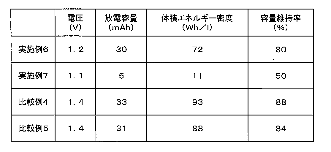
表2に示すように、塩化ナトリウム水溶液(pH=7)を電解液として用い、多孔性のカーボンシートであるカーボンペーパーを正極の集電体に使用した実施例6のシート状空気電池は、電解液による集電体の腐食を防ぐことができたため、汎用の金属網を正極の集電体に使用した実施例7の電池に比べて、放電容量、すなわち体積エネルギー密度が大きく、また、負荷特性も優れていた。
一方、比較例4および比較例5の電池の評価結果より明らかなように、強アルカリ性の水溶液を電解液として用いた電池では、正極の集電体の材質による特性差が小さく、電解液による集電体の腐食の問題は、ほとんど生じなかった。
(実施例8~実施例16)
電解質となる塩の種類およびその濃度を変えて表3に示す電解液を調製し、それぞれの電解液を用いた以外は実施例6と同様にして、シート状空気電池を作製した。電池の組み立て前に、それぞれの電解液について、横河電機製の「パーソナルSCメータ SC72」を用い、25℃環境下で導電率の測定を行った。
電解質となる塩の種類およびその濃度を変えて表3に示す電解液を調製し、それぞれの電解液を用いた以外は実施例6と同様にして、シート状空気電池を作製した。電池の組み立て前に、それぞれの電解液について、横河電機製の「パーソナルSCメータ SC72」を用い、25℃環境下で導電率の測定を行った。
なお、実施例16を除き、いずれの電解液も、過塩素酸イオンの含有量、および、鉄イオンを除く重金属イオンの含有量は、それぞれ100ppm未満であった。

実施例8~12のシート状空気電池に対し、組み立て後に大気中で10分間放置してから、前記の「開路電圧の測定」、「放電容量測定」および「負荷特性評価」を行った。また、実施例13~16のシート状空気電池に対し、3.9kΩでの定抵抗放電による放電容量の測定を行った。
それらの測定結果を、表4に示す。

実施例8~12のシート状電池の評価結果より、電解液の導電率を80mS/cm以上、特に150mS/cm以上とすることにより、電池の放電容量が大きくなり、また負荷特性も向上することがわかる。
また、強酸と弱塩基の塩である硫酸鉄(III)を電解質として用いた実施例13の電池は、電解液の導電率が40mS/cmと低いにもかかわらず、比較的大きな放電容量を示しており、電解液の導電率が同程度の、塩化ナトリウム(強酸と強塩基との塩)を用いた実施例10の電池、酢酸ナトリウム(弱酸と強塩基との塩)を用いた実施例14の電池、および酢酸アンモニウム(弱酸と弱塩基との塩)を用いた実施例15の電池よりも優れた特性を示した。
また、強酸と弱塩基の塩のうち、アンモニウム塩、アルミニウム塩、マグネシウム塩および鉄塩のいずれにも該当しない塩化亜鉛を用いた実施例16の電池よりも、鉄塩を用いた実施例13の電池の方が、電解液の導電率が低いにもかかわらず大きな放電容量が得られたことから、特定の塩を電解質として用いることにより、電池特性のより一層の向上が可能となることがわかる。
本発明は、その趣旨を逸脱しない範囲で、前記以外の形態としても実施が可能である。本出願に開示された実施形態は一例であって、本発明は、これらの実施形態には限定されない。本発明の範囲は、前記の明細書の記載よりも、添付されている請求の範囲の記載を優先して解釈され、請求の範囲と均等の範囲内での全ての変更は、請求の範囲に含まれる。
前記の通り、本発明の空気電池は、身体に装着可能なパッチなのど、医療・健康用途の機器の電源として好適であり、また、従来から知られている空気電池が採用されている用途と同じ用途にも適用することができる。
1 空気電池
20 正極(空気極)
21 正極外部端子
30 負極
31 負極外部端子
40 セパレータ
50 撥水膜
60 シート状外装体
61 空気孔
20 正極(空気極)
21 正極外部端子
30 負極
31 負極外部端子
40 セパレータ
50 撥水膜
60 シート状外装体
61 空気孔
Claims (12)
- 触媒およびバインダーを含有する触媒層を有する正極、金属材料を含有する負極、セパレータおよび電解液が、外装体内に収容されている空気電池であって、
前記セパレータは、透気度が10sec/100ml以上であり、
前記電解液は、pHが3以上12未満の水溶液であることを特徴とする空気電池。 - 前記セパレータとして、半透膜を有する請求項1に記載の空気電池。
- 前記電解液は、電解質として強酸と弱塩基との塩を含有する請求項1または2に記載の空気電池。
- 前記強酸と弱塩基との塩として、アンモニウム塩、アルミニウム塩、マグネシウム塩および鉄塩より選択される少なくとも1種の塩を含有する請求項3に記載の空気電池。
- 前記電解液中での電解質の濃度が、1mol/l以上である請求項4に記載の空気電池。
- 前記正極は、集電体としてカーボン製の多孔性シートを有する請求項1に記載の空気電池。
- 触媒およびバインダーを含有する触媒層を有する正極、金属材料を含有する負極、セパレータおよび電解液が、外装体内に収容されている空気電池であって、
前記正極は、集電体としてカーボン製の多孔性シートを有し、
前記電解液は、pHが3以上12未満の水溶液であることを特徴とする空気電池。 - 前記電解液は、電解質として強酸と弱塩基との塩を含有する請求項7に記載の空気電池。
- 前記強酸と弱塩基との塩として、アンモニウム塩、アルミニウム塩、マグネシウム塩および鉄塩より選択される少なくとも1種の塩を含有する請求項8に記載の空気電池。
- 前記電解液中での電解質の濃度が、1mol/l以上である請求項9に記載の空気電池。
- 樹脂フィルム製のシート状外装体を前記外装体として有する請求項1または7に記載の空気電池。
- 身体に装着可能なパッチであって、
電源として、請求項1~11のいずれかに記載の空気電池を備えたことを特徴とするパッチ。
Priority Applications (3)
| Application Number | Priority Date | Filing Date | Title |
|---|---|---|---|
| JP2018540263A JP7008630B2 (ja) | 2016-09-20 | 2017-09-20 | 空気電池およびパッチ |
| US16/331,337 US10950910B2 (en) | 2016-09-20 | 2017-09-20 | Air cell and patch |
| EP17853077.0A EP3518339A4 (en) | 2016-09-20 | 2017-09-20 | AIR DEPOLARIZATION BATTERY AND PATCH |
Applications Claiming Priority (10)
| Application Number | Priority Date | Filing Date | Title |
|---|---|---|---|
| JP2016-182814 | 2016-09-20 | ||
| JP2016182814 | 2016-09-20 | ||
| JP2017-041205 | 2017-03-06 | ||
| JP2017041205 | 2017-03-06 | ||
| JP2017-044497 | 2017-03-09 | ||
| JP2017044497 | 2017-03-09 | ||
| JP2017130902 | 2017-07-04 | ||
| JP2017-130902 | 2017-07-04 | ||
| JP2017-154905 | 2017-08-10 | ||
| JP2017154905 | 2017-08-10 |
Publications (1)
| Publication Number | Publication Date |
|---|---|
| WO2018056307A1 true WO2018056307A1 (ja) | 2018-03-29 |
Family
ID=61691016
Family Applications (1)
| Application Number | Title | Priority Date | Filing Date |
|---|---|---|---|
| PCT/JP2017/033912 Ceased WO2018056307A1 (ja) | 2016-09-20 | 2017-09-20 | 空気電池およびパッチ |
Country Status (4)
| Country | Link |
|---|---|
| US (1) | US10950910B2 (ja) |
| EP (1) | EP3518339A4 (ja) |
| JP (1) | JP7008630B2 (ja) |
| WO (1) | WO2018056307A1 (ja) |
Cited By (6)
| Publication number | Priority date | Publication date | Assignee | Title |
|---|---|---|---|---|
| JP2020109736A (ja) * | 2018-12-28 | 2020-07-16 | 凸版印刷株式会社 | 電極触媒層、膜電極接合体、および、固体高分子形燃料電池 |
| WO2020162591A1 (ja) | 2019-02-08 | 2020-08-13 | マクセルホールディングス株式会社 | 水系電解液電池用負極およびシート状電池 |
| WO2020213741A1 (ja) * | 2019-04-18 | 2020-10-22 | マクセルホールディングス株式会社 | 水系電解液電池およびパッチ |
| JPWO2021145345A1 (ja) * | 2020-01-17 | 2021-07-22 | ||
| JP2022068077A (ja) * | 2020-10-21 | 2022-05-09 | 光廣 佐想 | 金属銅をカソード電極とする1コンパートメント型水溶液燃料電池 |
| JPWO2023233522A1 (ja) * | 2022-05-31 | 2023-12-07 |
Families Citing this family (3)
| Publication number | Priority date | Publication date | Assignee | Title |
|---|---|---|---|---|
| WO2019064637A1 (ja) * | 2017-09-28 | 2019-04-04 | マクセルホールディングス株式会社 | シート状空気電池、その製造方法およびパッチ |
| WO2020017459A1 (ja) * | 2018-07-20 | 2020-01-23 | マクセルホールディングス株式会社 | 電池ロールおよびその製造方法 |
| CN111665672B (zh) * | 2020-06-10 | 2023-03-21 | 宁波祢若电子科技有限公司 | 一种双功能电致变色能量存储器件及其制作方法 |
Citations (9)
| Publication number | Priority date | Publication date | Assignee | Title |
|---|---|---|---|---|
| JP2001307746A (ja) | 2000-04-20 | 2001-11-02 | Hitachi Maxell Ltd | アルカリ電池 |
| JP2010534084A (ja) * | 2007-07-20 | 2010-11-04 | メディンゴ・リミテッド | 流体投与装置用のエネルギ供給 |
| JP2013020797A (ja) * | 2011-07-11 | 2013-01-31 | Sekisui Chem Co Ltd | アニオンフィルター、アニオンフィルターを用いた電解質体−電極接合体、及びアニオンフィルターを用いた二次電池 |
| JP2014154225A (ja) * | 2013-02-05 | 2014-08-25 | Sony Corp | 電極材料、電極及び電池 |
| JP2014165099A (ja) * | 2013-02-27 | 2014-09-08 | Sumitomo Chemical Co Ltd | 空気二次電池 |
| JP2015053136A (ja) * | 2013-09-05 | 2015-03-19 | スズキ株式会社 | リチウム空気電池および正極複合体 |
| WO2016006292A1 (ja) * | 2014-07-09 | 2016-01-14 | 日本碍子株式会社 | 金属空気電池用セパレータ付き空気極 |
| JP2016046116A (ja) | 2014-08-22 | 2016-04-04 | 株式会社日本触媒 | 亜鉛負極 |
| JP2016146257A (ja) | 2015-02-06 | 2016-08-12 | 古河電池株式会社 | 金属空気電池 |
Family Cites Families (6)
| Publication number | Priority date | Publication date | Assignee | Title |
|---|---|---|---|---|
| JP2006019246A (ja) | 2004-06-01 | 2006-01-19 | Matsushita Electric Ind Co Ltd | アルカリ電池の外装体用薄膜およびそれを用いた薄型空気電池 |
| DE112005000085T5 (de) | 2004-06-01 | 2013-10-10 | Panasonic Corporation | Dünner Film für eine Baugruppe einer Alkalibatterie und dünne Luftbatterie, welche diesen einsetzt |
| US20130078537A1 (en) * | 2011-09-23 | 2013-03-28 | Bayer Intellectual Property Gmbh | Oxygen-consuming electrode and process for production thereof |
| US10164237B2 (en) * | 2013-08-26 | 2018-12-25 | Nissan Motor Co., Ltd. | Air battery cell with electrically conductive members and battery pack |
| WO2016086903A1 (zh) * | 2014-12-05 | 2016-06-09 | 兰州金福乐生物工程有限公司 | 空气金属燃料电池 |
| US9693689B2 (en) * | 2014-12-31 | 2017-07-04 | Blue Spark Technologies, Inc. | Body temperature logging patch |
-
2017
- 2017-09-20 JP JP2018540263A patent/JP7008630B2/ja active Active
- 2017-09-20 WO PCT/JP2017/033912 patent/WO2018056307A1/ja not_active Ceased
- 2017-09-20 EP EP17853077.0A patent/EP3518339A4/en active Pending
- 2017-09-20 US US16/331,337 patent/US10950910B2/en active Active
Patent Citations (9)
| Publication number | Priority date | Publication date | Assignee | Title |
|---|---|---|---|---|
| JP2001307746A (ja) | 2000-04-20 | 2001-11-02 | Hitachi Maxell Ltd | アルカリ電池 |
| JP2010534084A (ja) * | 2007-07-20 | 2010-11-04 | メディンゴ・リミテッド | 流体投与装置用のエネルギ供給 |
| JP2013020797A (ja) * | 2011-07-11 | 2013-01-31 | Sekisui Chem Co Ltd | アニオンフィルター、アニオンフィルターを用いた電解質体−電極接合体、及びアニオンフィルターを用いた二次電池 |
| JP2014154225A (ja) * | 2013-02-05 | 2014-08-25 | Sony Corp | 電極材料、電極及び電池 |
| JP2014165099A (ja) * | 2013-02-27 | 2014-09-08 | Sumitomo Chemical Co Ltd | 空気二次電池 |
| JP2015053136A (ja) * | 2013-09-05 | 2015-03-19 | スズキ株式会社 | リチウム空気電池および正極複合体 |
| WO2016006292A1 (ja) * | 2014-07-09 | 2016-01-14 | 日本碍子株式会社 | 金属空気電池用セパレータ付き空気極 |
| JP2016046116A (ja) | 2014-08-22 | 2016-04-04 | 株式会社日本触媒 | 亜鉛負極 |
| JP2016146257A (ja) | 2015-02-06 | 2016-08-12 | 古河電池株式会社 | 金属空気電池 |
Non-Patent Citations (1)
| Title |
|---|
| See also references of EP3518339A4 |
Cited By (16)
| Publication number | Priority date | Publication date | Assignee | Title |
|---|---|---|---|---|
| JP2020109736A (ja) * | 2018-12-28 | 2020-07-16 | 凸版印刷株式会社 | 電極触媒層、膜電極接合体、および、固体高分子形燃料電池 |
| JP7293832B2 (ja) | 2018-12-28 | 2023-06-20 | 凸版印刷株式会社 | 電極触媒層、膜電極接合体、および、固体高分子形燃料電池 |
| EP3916864A4 (en) * | 2019-02-08 | 2022-04-06 | Maxell, Ltd. | NEGATIVE ELECTRODE FOR BATTERIES WITH AQUEOUS ELECTROLYTIC SOLUTION AND LEAF-SHAPED BATTERY |
| WO2020162591A1 (ja) | 2019-02-08 | 2020-08-13 | マクセルホールディングス株式会社 | 水系電解液電池用負極およびシート状電池 |
| CN113474925B (zh) * | 2019-02-08 | 2024-11-15 | 麦克赛尔株式会社 | 水系电解液电池用负极和片状电池 |
| CN113474925A (zh) * | 2019-02-08 | 2021-10-01 | 麦克赛尔控股株式会社 | 水系电解液电池用负极和片状电池 |
| JP2025061390A (ja) * | 2019-04-18 | 2025-04-10 | マクセル株式会社 | 水系電解液電池およびパッチ |
| JPWO2020213741A1 (ja) * | 2019-04-18 | 2020-10-22 | ||
| WO2020213741A1 (ja) * | 2019-04-18 | 2020-10-22 | マクセルホールディングス株式会社 | 水系電解液電池およびパッチ |
| JP7802973B2 (ja) | 2019-04-18 | 2026-01-20 | マクセル株式会社 | 水系電解液電池およびパッチ |
| JPWO2021145345A1 (ja) * | 2020-01-17 | 2021-07-22 | ||
| JP7386265B2 (ja) | 2020-01-17 | 2023-11-24 | 富士フイルム株式会社 | 非水電解質二次電池、集電体、及びこれらの製造方法 |
| US12555828B2 (en) | 2020-01-17 | 2026-02-17 | Fujifilm Corporation | Non-aqueous electrolyte secondary battery, collector, method for manufacturing non- aqueous electrolyte secondary battery, and method for manufacturing collector |
| JP2022068077A (ja) * | 2020-10-21 | 2022-05-09 | 光廣 佐想 | 金属銅をカソード電極とする1コンパートメント型水溶液燃料電池 |
| JP7678547B2 (ja) | 2020-10-21 | 2025-05-16 | クロステクノロジーラボ株式会社 | 金属銅をカソード電極とする1コンパートメント型水溶液燃料電池 |
| JPWO2023233522A1 (ja) * | 2022-05-31 | 2023-12-07 |
Also Published As
| Publication number | Publication date |
|---|---|
| EP3518339A4 (en) | 2020-07-29 |
| US20190363412A1 (en) | 2019-11-28 |
| JP7008630B2 (ja) | 2022-01-25 |
| EP3518339A1 (en) | 2019-07-31 |
| US10950910B2 (en) | 2021-03-16 |
| JPWO2018056307A1 (ja) | 2019-07-04 |
Similar Documents
| Publication | Publication Date | Title |
|---|---|---|
| JP7008630B2 (ja) | 空気電池およびパッチ | |
| JP7744942B2 (ja) | シート状空気電池およびパッチ | |
| JP7354092B2 (ja) | シート状電池、および、パッチ | |
| CN113474925B (zh) | 水系电解液电池用负极和片状电池 | |
| WO2019065029A1 (ja) | 防水デバイス | |
| JP7017354B2 (ja) | シート状空気電池およびパッチ | |
| JP7406545B2 (ja) | シート状電池およびその製造方法 | |
| JP7802973B2 (ja) | 水系電解液電池およびパッチ | |
| WO2020017459A1 (ja) | 電池ロールおよびその製造方法 | |
| JP7534098B2 (ja) | シート状電池およびパッチ | |
| JP7536480B2 (ja) | シート状空気電池およびパッチ | |
| JP7744767B2 (ja) | 一次電池およびその製造方法 | |
| JP2019067754A (ja) | シート状空気電池およびパッチ | |
| JP6938416B2 (ja) | シート状電池の製造方法 | |
| JP2018049687A (ja) | シート状空気電池 | |
| JPWO2023140225A5 (ja) | ||
| JP2024087948A (ja) | 電池 | |
| WO2025070355A1 (ja) | 電池 | |
| WO2023140225A1 (ja) | 電池およびパッチ |
Legal Events
| Date | Code | Title | Description |
|---|---|---|---|
| WWE | Wipo information: entry into national phase |
Ref document number: 2018540263 Country of ref document: JP |
|
| 121 | Ep: the epo has been informed by wipo that ep was designated in this application |
Ref document number: 17853077 Country of ref document: EP Kind code of ref document: A1 |
|
| NENP | Non-entry into the national phase |
Ref country code: DE |
|
| ENP | Entry into the national phase |
Ref document number: 2017853077 Country of ref document: EP Effective date: 20190423 |