WO2018055940A1 - メッシュ式ネブライザおよび薬液パック - Google Patents
メッシュ式ネブライザおよび薬液パック Download PDFInfo
- Publication number
- WO2018055940A1 WO2018055940A1 PCT/JP2017/028910 JP2017028910W WO2018055940A1 WO 2018055940 A1 WO2018055940 A1 WO 2018055940A1 JP 2017028910 W JP2017028910 W JP 2017028910W WO 2018055940 A1 WO2018055940 A1 WO 2018055940A1
- Authority
- WO
- WIPO (PCT)
- Prior art keywords
- mesh
- peripheral wall
- main body
- chemical
- pack
- Prior art date
- Legal status (The legal status is an assumption and is not a legal conclusion. Google has not performed a legal analysis and makes no representation as to the accuracy of the status listed.)
- Ceased
Links
Images




Classifications
-
- A—HUMAN NECESSITIES
- A61—MEDICAL OR VETERINARY SCIENCE; HYGIENE
- A61M—DEVICES FOR INTRODUCING MEDIA INTO, OR ONTO, THE BODY; DEVICES FOR TRANSDUCING BODY MEDIA OR FOR TAKING MEDIA FROM THE BODY; DEVICES FOR PRODUCING OR ENDING SLEEP OR STUPOR
- A61M11/00—Sprayers or atomisers specially adapted for therapeutic purposes
- A61M11/005—Sprayers or atomisers specially adapted for therapeutic purposes using ultrasonics
-
- A—HUMAN NECESSITIES
- A61—MEDICAL OR VETERINARY SCIENCE; HYGIENE
- A61M—DEVICES FOR INTRODUCING MEDIA INTO, OR ONTO, THE BODY; DEVICES FOR TRANSDUCING BODY MEDIA OR FOR TAKING MEDIA FROM THE BODY; DEVICES FOR PRODUCING OR ENDING SLEEP OR STUPOR
- A61M15/00—Inhalators
- A61M15/0001—Details of inhalators; Constructional features thereof
- A61M15/0021—Mouthpieces therefor
- A61M15/0023—Mouthpieces therefor retractable
-
- A—HUMAN NECESSITIES
- A61—MEDICAL OR VETERINARY SCIENCE; HYGIENE
- A61M—DEVICES FOR INTRODUCING MEDIA INTO, OR ONTO, THE BODY; DEVICES FOR TRANSDUCING BODY MEDIA OR FOR TAKING MEDIA FROM THE BODY; DEVICES FOR PRODUCING OR ENDING SLEEP OR STUPOR
- A61M15/00—Inhalators
- A61M15/0028—Inhalators using prepacked dosages, one for each application, e.g. capsules to be perforated or broken-up
-
- A—HUMAN NECESSITIES
- A61—MEDICAL OR VETERINARY SCIENCE; HYGIENE
- A61M—DEVICES FOR INTRODUCING MEDIA INTO, OR ONTO, THE BODY; DEVICES FOR TRANSDUCING BODY MEDIA OR FOR TAKING MEDIA FROM THE BODY; DEVICES FOR PRODUCING OR ENDING SLEEP OR STUPOR
- A61M15/00—Inhalators
- A61M15/0085—Inhalators using ultrasonics
-
- B—PERFORMING OPERATIONS; TRANSPORTING
- B05—SPRAYING OR ATOMISING IN GENERAL; APPLYING FLUENT MATERIALS TO SURFACES, IN GENERAL
- B05B—SPRAYING APPARATUS; ATOMISING APPARATUS; NOZZLES
- B05B17/00—Apparatus for spraying or atomising liquids or other fluent materials, not covered by the preceding groups
- B05B17/04—Apparatus for spraying or atomising liquids or other fluent materials, not covered by the preceding groups operating with special methods
- B05B17/06—Apparatus for spraying or atomising liquids or other fluent materials, not covered by the preceding groups operating with special methods using ultrasonic or other kinds of vibrations
-
- B—PERFORMING OPERATIONS; TRANSPORTING
- B05—SPRAYING OR ATOMISING IN GENERAL; APPLYING FLUENT MATERIALS TO SURFACES, IN GENERAL
- B05B—SPRAYING APPARATUS; ATOMISING APPARATUS; NOZZLES
- B05B17/00—Apparatus for spraying or atomising liquids or other fluent materials, not covered by the preceding groups
- B05B17/04—Apparatus for spraying or atomising liquids or other fluent materials, not covered by the preceding groups operating with special methods
- B05B17/06—Apparatus for spraying or atomising liquids or other fluent materials, not covered by the preceding groups operating with special methods using ultrasonic or other kinds of vibrations
- B05B17/0607—Apparatus for spraying or atomising liquids or other fluent materials, not covered by the preceding groups operating with special methods using ultrasonic or other kinds of vibrations generated by electrical means, e.g. piezoelectric transducers
- B05B17/0623—Apparatus for spraying or atomising liquids or other fluent materials, not covered by the preceding groups operating with special methods using ultrasonic or other kinds of vibrations generated by electrical means, e.g. piezoelectric transducers coupled with a vibrating horn
-
- A—HUMAN NECESSITIES
- A61—MEDICAL OR VETERINARY SCIENCE; HYGIENE
- A61M—DEVICES FOR INTRODUCING MEDIA INTO, OR ONTO, THE BODY; DEVICES FOR TRANSDUCING BODY MEDIA OR FOR TAKING MEDIA FROM THE BODY; DEVICES FOR PRODUCING OR ENDING SLEEP OR STUPOR
- A61M2202/00—Special media to be introduced, removed or treated
- A61M2202/04—Liquids
- A61M2202/0468—Liquids non-physiological
-
- A—HUMAN NECESSITIES
- A61—MEDICAL OR VETERINARY SCIENCE; HYGIENE
- A61M—DEVICES FOR INTRODUCING MEDIA INTO, OR ONTO, THE BODY; DEVICES FOR TRANSDUCING BODY MEDIA OR FOR TAKING MEDIA FROM THE BODY; DEVICES FOR PRODUCING OR ENDING SLEEP OR STUPOR
- A61M2205/00—General characteristics of the apparatus
- A61M2205/02—General characteristics of the apparatus characterised by a particular materials
- A61M2205/0216—Materials providing elastic properties, e.g. for facilitating deformation and avoid breaking
-
- A—HUMAN NECESSITIES
- A61—MEDICAL OR VETERINARY SCIENCE; HYGIENE
- A61M—DEVICES FOR INTRODUCING MEDIA INTO, OR ONTO, THE BODY; DEVICES FOR TRANSDUCING BODY MEDIA OR FOR TAKING MEDIA FROM THE BODY; DEVICES FOR PRODUCING OR ENDING SLEEP OR STUPOR
- A61M2205/00—General characteristics of the apparatus
- A61M2205/12—General characteristics of the apparatus with interchangeable cassettes forming partially or totally the fluid circuit
- A61M2205/123—General characteristics of the apparatus with interchangeable cassettes forming partially or totally the fluid circuit with incorporated reservoirs
-
- A—HUMAN NECESSITIES
- A61—MEDICAL OR VETERINARY SCIENCE; HYGIENE
- A61M—DEVICES FOR INTRODUCING MEDIA INTO, OR ONTO, THE BODY; DEVICES FOR TRANSDUCING BODY MEDIA OR FOR TAKING MEDIA FROM THE BODY; DEVICES FOR PRODUCING OR ENDING SLEEP OR STUPOR
- A61M2205/00—General characteristics of the apparatus
- A61M2205/82—Internal energy supply devices
- A61M2205/8206—Internal energy supply devices battery-operated
-
- A—HUMAN NECESSITIES
- A61—MEDICAL OR VETERINARY SCIENCE; HYGIENE
- A61M—DEVICES FOR INTRODUCING MEDIA INTO, OR ONTO, THE BODY; DEVICES FOR TRANSDUCING BODY MEDIA OR FOR TAKING MEDIA FROM THE BODY; DEVICES FOR PRODUCING OR ENDING SLEEP OR STUPOR
- A61M2210/00—Anatomical parts of the body
- A61M2210/06—Head
- A61M2210/0625—Mouth
Definitions
- the present invention relates to a mesh type nebulizer, and more particularly to a mesh type nebulizer that atomizes a liquid supplied between a vibrating surface and a mesh portion and ejects the liquid through the mesh portion.
- the present invention also relates to a chemical pack suitable for constituting such a mesh nebulizer.
- the main body is provided with a horn vibrator, and can be attached to and detached from the main body and can be opened and closed (rotated). It is known to have a mesh cap that can be moved).
- the vibration surface of the horn vibrator faces the mesh portion of the mesh cap.
- a chemical solution is supplied between the vibration surface and the mesh portion, and a driving voltage is applied to the horn vibrator to vibrate the vibration surface.
- medical solution is atomized through the said mesh part, and it ejects.
- the mesh type nebulizer it is necessary to remove the mesh cap from the main body each time after use, and to wash, disinfect, and dry the mesh cap including the mesh portion. For this reason, there is a problem that care is troublesome for the user. Furthermore, since the mesh cap is a precision part, there is a problem that it is easily damaged by cleaning and is difficult to clean. Further, if the mesh part is not properly cleaned, there is a problem that it is unsanitary and the spray efficiency is lowered.
- an object of the present invention is to provide a mesh type nebulizer that is hygienic and can be easily maintained by a user without lowering the spray efficiency.
- an object of the present invention is to provide a chemical pack suitable for constructing such a mesh nebulizer.
- the mesh nebulizer of the present invention is It is a mesh type nebulizer that atomizes and ejects chemicals through the mesh part, A main body provided with a vibration part having a vibration surface; A chemical pack that is detachably attached to the main body, The above chemical pack is A lid member on which the mesh portion is formed; It has a recess that opens toward the mesh portion and is covered with the lid member, and a chemical solution storage member that stores a chemical solution to be supplied toward the vibration surface in the recess.
- the bottom surface of the concave portion of the chemical solution storage member at least a portion to be opposed to the vibration surface is formed of a material having extensibility, When the chemical pack is attached to the main body, the stretchable material on the bottom surface extends to allow the vibration surface to approach the mesh portion of the lid member.
- the planar shape of the concave portion widely includes an annular shape such as a circle and a rounded square (a square with rounded corners).
- a chemical pack is detachably attached to the main body in advance for use.
- This chemical solution pack includes a lid member in which a mesh portion is formed and a chemical solution storage member that has a concave portion that opens toward the mesh portion and is covered by the lid member, and in which the chemical solution is accommodated. Yes.
- at least a portion of the bottom surface of the concave portion of the chemical solution storage member that should face the vibration surface is formed of a stretchable material.
- the chemical pack is removed from the main body and discarded.
- the mesh type nebulizer of the present invention is equipped with a new chemical pack every time it is used, it is not necessary to clean the mesh portion. Therefore, it is hygienic and easy to clean for the user without reducing the spray efficiency. Furthermore, since a new mesh part is used every time it is used, it is hygienic and the spray efficiency is not reduced.
- the main body An inner peripheral wall surrounding the vibration surface; An outer peripheral wall that is concentric with the inner peripheral wall and is rotatably arranged around the inner peripheral wall; A cylindrical member that is interposed between the inner peripheral wall and the outer peripheral wall, and a holder member that receives and holds the drug pack through an opening formed in a part of the peripheral wall; An elevating mechanism is provided for raising or lowering the holder member relative to the inner peripheral wall as the outer peripheral wall of the main body is rotated around the inner peripheral wall.
- the main body has a cylindrical holder member in which a chemical pack is to be held.
- the holder member is provided with an opening in a part of the peripheral wall in which the chemical pack is to be taken in and out, and the peripheral wall is arranged inside the outer peripheral wall.
- an elevating mechanism is provided for raising or lowering the holder member with respect to the inner peripheral wall as the outer peripheral wall is rotated around the inner peripheral wall.
- the elevating mechanism lowers the holder member, and the opening portion of the peripheral wall can be arranged inside the outer peripheral wall.
- the outer peripheral wall is rotated around the inner peripheral wall, and when the holder member is lowered with respect to the inner peripheral wall by the lifting mechanism, The bottom surface approaches and comes into contact with the vibration surface. And the raw material which has the said extensibility of the said bottom face of the said chemical
- the chemical pack is removed from the main body, the outer peripheral wall is rotated around the inner peripheral wall, and when the holder member is raised with respect to the inner peripheral wall by the elevating mechanism, the chemical pack is vibrated. Separate from the surface. In this way, the user can remove the chemical pack from the main body.
- the lifting mechanism includes a first screw element provided on the outer peripheral surface of the holder member, and a second screw element formed on the inner surface of the outer peripheral wall of the main body so as to be able to engage with the first screw element. It is provided with.
- the first screw element is formed on the outer peripheral surface of the holder member, and the second screw element that engages with the first screw element is formed on the inner surface of the outer peripheral wall. For this reason, it becomes possible to raise or lower the holder member by rotating the outer peripheral wall. Furthermore, since the screw elements are configured only by forming grooves on the respective surfaces, the screw elements can be easily configured and are not easily damaged.
- the chemical pack of the present invention is a chemical pack to be attached to the mesh nebulizer, A lid member on which the mesh portion is formed; It has a recess that opens toward the mesh portion and is covered with the lid member, and a chemical solution storage member that stores a chemical solution to be supplied toward the vibration surface in the recess.
- a portion to be opposed to the vibration surface is formed of a material having extensibility.
- the chemical pack of the present invention is suitable for constituting the mesh nebulizer.
- the lid member includes a flange portion formed by extending outward from the upper edge of the chemical solution storage member, When the chemical pack is attached to the main body, the flange portion of the lid member is supported by the upper edge of the inner peripheral wall surrounding the vibration surface of the main body.
- the lid member includes a flange portion formed to extend outward from the upper edge of the chemical solution storage member. Therefore, when the chemical pack is attached to the main body, the flange portion of the lid member can be supported by the upper edge of the inner peripheral wall of the main body.
- the lid member has a flat shape
- the recess includes a deep first region where the chemical solution is stored and a second region shallower than the first region,
- the bottom surface of the concave portion of the chemical solution storage member to be opposed to the vibration surface is disposed in the second region.
- the concave portion has a shallow region and a deep region, and the bottom surface of the concave portion of the chemical solution storage member to be opposed to the vibration surface is disposed in the shallow region.
- the mesh nebulizer of the present invention is easy to care for the user. Furthermore, since a new mesh part is used every time it is used, it is hygienic and the spray efficiency is not reduced.
- the chemical pack of the present invention is suitable for constituting the mesh nebulizer.
- the place which looked at the mesh type nebulizer of one Embodiment of this invention from diagonally is shown. It is a perspective view of the chemical
- the block configuration of the control system mounted in the main body of the mesh type nebulizer of FIG. 1 is shown.
- FIG. 1 shows a mesh type nebulizer according to an embodiment of the present invention (the whole is denoted by reference numeral 1) as viewed obliquely.
- the mesh nebulizer 1 includes a main body lower part 11 having a substantially cylindrical outer shape, and a main body upper part 12 fitted to the main body lower part 11 and having a substantially cylindrical outer shape.
- the main body upper portion 12 is fitted to the main body lower portion 11 and can be rotated in the circumferential direction (arrow A), and a cylinder that rises or falls in the vertical direction (arrow B) according to the rotation of the outer peripheral wall 31.
- Shaped holder member 30 The holder member 30 holds a chemical pack 20 to be described later.
- the main body lower portion 11 and the main body upper portion 12 constitute a main body 10.
- a power switch 50 for turning on / off the power supply of the nebulizer 1 is provided on the front surface of the lower part 11 of the main body.
- a control system which will be described later is mainly mounted in the lower part 11 of the main body.
- an opening 30o is provided on the upper surface 30a of the holder member 30, and a mouthpiece 80, for example, is detachably attached to the opening 30o.
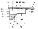
- FIG. 2A is a perspective view of the chemical pack 20 attached to the mesh nebulizer 1 of FIG. 1, and FIG. 2B is a longitudinal sectional view taken along the line DD of FIG. 2A.
- the chemical solution pack 20 includes a chemical solution storage member 24 having a recess 17 and a lid member 21 that covers the chemical solution storage member 24 and has a substantially flat shape.
- the chemical solution storage member 24 of the chemical solution pack 20 includes a deep first region R1 in which the chemical solution 23 is stored and a second region R2 that is shallower than the first region R1.
- the bottom surface 24c of the concave portion 17 of the chemical solution storage member 24 to be opposed to a vibration surface 43 described later is disposed in the second region.
- a portion 24d of the bottom surface 24c of the concave portion 17 of the chemical solution storage member 24 that should face a vibration surface 43 described later is formed of a material having extensibility.
- a mesh portion 24 a is formed in the approximate center of the lid member 21 of the chemical pack 20.
- the lid member 21 includes a flange portion 21 a formed by extending outward from the upper edge 24 b of the side wall 24 e of the chemical solution storage member 24.
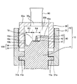
- FIG. 3 is a view showing a part of a longitudinal section when the mesh nebulizer 1 of FIG. 1 is viewed from the right side (the direction indicated by the arrow C in FIG. 1).
- FIG. 3 shows the mesh nebulizer 1 in a state where the chemical pack 20 is not attached to the main body 10 of the mesh nebulizer 1.
- the lower part 11 of the main body includes an inner peripheral wall 16 c surrounding the vibration surface 43.
- the vibration surface 43 and the inner peripheral wall 16c are integrally formed.
- the main body upper portion 12 includes an outer peripheral wall 31 that is concentric with the inner peripheral wall 16c of the main body lower portion 11 and is rotatably arranged around the inner peripheral wall 16c.
- a convex portion 11a is formed in a ring shape along the outer periphery above the lower portion 11 of the main body.
- the outer peripheral wall 31 of the main body upper portion 12 is formed with a concave portion 31 a that is fitted to the convex portion 11 a of the lower main body 11. With this configuration, the outer peripheral wall 31 of the main body upper portion 12 can be rotated in the circumferential direction.
- a concave portion 16 opened upward is provided on the upper surface of the lower part 11 of the main body so that the chemical pack 20 can be fitted.
- the concave portion 16 includes a third region R3 fitted into the first region R1 of the chemical solution pack 20 of FIGS. 2A and 2B and a fourth region fitted into the second region R2 of the chemical solution pack 20.
- the third region R3 is deeper than the fourth region R4.
- the chemical pack 20 can be fitted into the recess 16.
- the flange portion 21 a of the lid member 21 of the chemical pack 20 is supported by the upper edge 16 a of the inner peripheral wall 16 c of the main body 10. Is done.
- a vibrating portion 40 is provided on the bottom surface 16b of the fourth region R4 of the recess 16.
- the vibration unit 40 includes an ultrasonic transducer 41 provided on the bottom surface 16b of the fourth region R4 of the recess 16, and a vibration surface 43 horizontally disposed at a position corresponding to the bottom surface 16b of the fourth region R4 of the recess 16.
- a horn 42 that is disposed between the ultrasonic transducer 41 and the vibration surface 43 and amplifies the vibration of the ultrasonic transducer 41 and transmits the vibration to the vibration surface 43.
- a driving voltage for the ultrasonic transducer 41 is supplied from the lower body 11 through a contact electrode provided between the upper body 12 and the lower body 11.
- the holder member 30 has an opening 30b in which a chemical pack 20 is to be taken in and out in a part of the peripheral wall.
- the peripheral wall of the holder member 30 is interposed between the inner peripheral wall 16 c and the outer peripheral wall 31. That is, the holder member 30 has a cylindrical peripheral wall inserted between the inner peripheral wall 16c and the outer peripheral wall 31, and receives and holds the drug solution pack 20 through an opening 30b formed in a part of the peripheral wall. .
- the mesh nebulizer 1 includes an elevating mechanism 100 that raises or lowers the holder member 30 relative to the main body 10 as the outer peripheral wall 31 of the main body 10 is rotated around the inner peripheral wall 16c.
- the lifting mechanism 100 includes a first screw element 33 provided on the outer peripheral surface of the holder member 30, and a second screw formed on the inner surface of the outer peripheral wall 31 of the main body 10 so as to be able to engage with the first screw element 33. And a screw element 34.
- the holder member 30 can be lowered. Therefore, the opening 30 b is arranged inside the outer peripheral wall 31, and the opening 30 b is closed by the outer peripheral wall 31.
- FIG. 4 shows a block configuration of a control system mounted on the main body 10 of the mesh nebulizer 1.
- the mesh nebulizer 1 includes an operation unit 61, a notification unit 62, a control unit 63, an oscillation frequency generation unit 64, an atomization unit 65, and a power supply unit 66.
- the operation unit 61 includes the power switch 50 shown in FIG.
- the notification unit 62 may include a buzzer (not shown), for example.
- the oscillation frequency generation unit 64 applies an alternating drive voltage to the atomization unit 65 based on a control signal from the control unit 63. This drive voltage is output over a certain output time after the power switch 50 is pressed, for example. The output time can be measured by a timer (not shown).
- the atomizing unit 65 includes the vibrating unit 40 and the mesh unit 24a of the chemical pack 20 shown in FIG.
- the AC drive voltage from the oscillation frequency generation unit 64 is applied to the ultrasonic transducer 41 of the vibration unit 40 that forms the atomization unit 65.
- the vibration of the ultrasonic transducer 41 is amplified by the horn 42 and transmitted to the vibration surface 43.
- the control unit 63 includes a CPU (Central Processing Unit) and sends a signal to the atomization unit 65 via the oscillation frequency generation unit 64 to control the atomization amount, the continuous operation time, and the like.
- CPU Central Processing Unit
- the control unit 63 notifies that the power is turned on, for example, by lighting or blinking of an LED lamp or the like, or that the battery capacity is insufficient.
- the power supply unit 66 includes a battery (for example, a DC3V chargeable / dischargeable secondary battery), and supplies power to each unit of the control system.
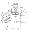
- (About wearing chemical pack 20) 5 shows the mesh nebulizer 1 in a state where the opening 30b of the holder member 30 of the mesh nebulizer 1 of FIG. Are shown.
- a user who intends to use the mesh nebulizer 1 rotates the outer peripheral wall 31 of the main body 10 in the direction indicated by the arrow E as shown in FIG.
- the holder member 30 formed with the first screw element 33 engaged with the second screw element 34 is raised in the direction indicated by the arrow F, and the opening 30b closed by the outer peripheral wall 31 is exposed.
- the user puts the medicinal solution pack 20 in the concave portion 16 of the main body 10 through the opening 30b and holds it.
- the user rotates the outer peripheral wall 31 of the main body 10 in the direction opposite to the arrow E in a state where the chemical pack 20 is mounted in the recess 16.
- the holder member 30 formed with the first screw element 33 engaged with the second screw element 34 is lowered in the direction opposite to the arrow F, and the opening 30 b is arranged inside the outer peripheral wall 31. That is, the opening 30 b is closed by the outer peripheral wall 31.
- the outer peripheral wall 31 When the chemical pack 20 is attached to the main body 10, the outer peripheral wall 31 is rotated around the inner peripheral wall 16c, and the holder member 30 is lowered with respect to the inner peripheral wall 16c by the lifting mechanism 100. Then, the bottom surface 24 c of the concave portion 17 of the chemical solution storage member 24 of the chemical solution pack 20 approaches and comes into contact with the vibration surface 43. Then, the material having the extensibility of the bottom surface 24 c extends, and the vibration surface 43 approaches the mesh portion 24 a of the lid member 21.
- the chemical pack 20 When the chemical pack 20 is removed from the main body 10, the outer peripheral wall 31 is rotated around the inner peripheral wall 16 c, and when the holder member 30 is raised relative to the inner peripheral wall 16 c by the lifting mechanism 100, the chemical pack 20 vibrates. Separate from the surface 43.
- FIG. 6 is a view showing a part of a longitudinal section when the mesh nebulizer 1 of FIG. 5 is viewed from the right side (the direction indicated by the arrow G in FIG. 5).
- FIG. 6 shows the mesh nebulizer 1 in a state where the chemical pack 20 is mounted in the recess 16 of the main body 10 of the mesh nebulizer 1.
- the user attaches the chemical pack 20 to the recess 16 of the main body 10 through the opening 30 b.
- the flange portion 21 a of the lid member 21 of the drug solution pack 20 is supported by the upper edge 16 a of the inner peripheral wall 16 c of the main body 10.
- the chemical solution 23 in the first region of FIG. 2B moves along the bottom surface 24 c of the concave portion 17 of the chemical solution pack 20. It is supplied toward the vibration surface 43. That is, the chemical solution is supplied between the vibration surface 43 and the mesh portion 24a.
- a driving voltage is applied to the ultrasonic transducer 41 of the vibrating unit 40 and the vibrating surface 43 is vibrated. Thereby, the chemical
- the chemical pack 20 is removed from the main body 10 and discarded.
- the mesh type nebulizer 1 of the present invention is equipped with a new chemical solution pack 20 every time it is used, it is not necessary to clean the mesh portion 24a. Therefore, it is hygienic and easy to clean for the user without reducing the spray efficiency. Furthermore, since the new mesh portion 24a is used every time it is used, it is hygienic and the spray efficiency does not decrease.
Landscapes
- Health & Medical Sciences (AREA)
- Engineering & Computer Science (AREA)
- Life Sciences & Earth Sciences (AREA)
- Biomedical Technology (AREA)
- Heart & Thoracic Surgery (AREA)
- Hematology (AREA)
- Anesthesiology (AREA)
- Animal Behavior & Ethology (AREA)
- General Health & Medical Sciences (AREA)
- Public Health (AREA)
- Veterinary Medicine (AREA)
- Bioinformatics & Cheminformatics (AREA)
- Pulmonology (AREA)
- Special Spraying Apparatus (AREA)
- Containers And Packaging Bodies Having A Special Means To Remove Contents (AREA)
Abstract
本発明の、メッシュ部(24a)を通して薬液(23)を霧化して噴出するメッシュ式ネブライザ(1)は、振動面(43)を有する振動部(40)を備えた本体(10)と、本体(10)に対して着脱可能に装着される薬液パック(20)とを備える。この薬液パック(20)は、メッシュ部(24a)が形成された蓋部材(21)と、メッシュ部(24a)へ向かって開き蓋部材(21)に覆われた凹部(17)を有し、この凹部(17)に薬液が収容された薬液収容部材(24)とを備えている。薬液収容部材(24)の凹部(17)の底面(24c)のうちの少なくとも振動面(43)に対向すべき部分は伸展性を有する素材で形成されている。薬液パック(20)が本体(10)に装着されると、底面(24c)の伸展性を有する素材が伸びて、振動面(43)が蓋部材(21)のメッシュ部(24a)に接近するのを許容する。
Description
この発明はメッシュ式ネブライザに関し、より詳しくは、振動面とメッシュ部との間に供給された液体を、上記メッシュ部を通して霧化して噴出するメッシュ式ネブライザに関する。
また、この発明は、そのようなメッシュ式ネブライザを構成するのに適した薬液パックに関する。
従来、この種のメッシュ式ネブライザとしては、例えば特許文献1(特開2014-4208号公報)に開示されているように、本体にホーン振動子を備え、本体に対して着脱可能および開閉(回動)可能に取り付けられたメッシュキャップを備えたものが知られている。本体に対してメッシュキャップが取り付けられ、閉じられた状態では、ホーン振動子の振動面とメッシュキャップのメッシュ部とが対向する。この状態で、振動面とメッシュ部との間に薬液が供給されるとともに、上記ホーン振動子に駆動電圧が印加されて振動面が振動される。これにより、上記メッシュ部を通して上記薬液が霧化されて噴出する。
しかしながら、上記メッシュ式ネブライザでは、使用後、その度に、本体からメッシュキャップを取り外し、メッシュ部を含むメッシュキャップを洗浄、消毒、乾燥する必要がある。このため、ユーザにとって、手入れが煩わしいという問題がある。さらに、上記メッシュキャップは精密部品であるため、洗浄によって破損し易く洗浄が困難であるという問題がある。また、メッシュ部が正しく洗浄されないと、不衛生でありかつ噴霧効率が低下するという問題がある。
そこで、この発明の課題は、衛生的でありかつ噴霧効率を低下させることなしに、ユーザにとって手入れが簡単となるメッシュ式ネブライザを提供することにある。
また、この発明の課題は、そのようなメッシュ式ネブライザを構成するのに適した薬液パックを提供することにある。
上記課題を解決するため、この発明のメッシュ式ネブライザは、
メッシュ部を通して薬液を霧化して噴出するメッシュ式ネブライザであって、
振動面を有する振動部を備えた本体と、
上記本体に対して着脱可能に装着される薬液パックとを備え、
上記薬液パックは、
上記メッシュ部が形成された蓋部材と、
上記メッシュ部へ向かって開き上記蓋部材に覆われた凹部を有し、この凹部に上記振動面上へ向けて供給すべき薬液が収容された薬液収容部材とを備え、
上記薬液収容部材の上記凹部の底面のうちの少なくとも上記振動面に対向すべき部分は伸展性を有する素材で形成され、
上記薬液パックが上記本体に装着されると、上記底面の上記伸展性を有する素材が伸びて、上記振動面が上記蓋部材の上記メッシュ部に接近するのを許容することを特徴とする。
メッシュ部を通して薬液を霧化して噴出するメッシュ式ネブライザであって、
振動面を有する振動部を備えた本体と、
上記本体に対して着脱可能に装着される薬液パックとを備え、
上記薬液パックは、
上記メッシュ部が形成された蓋部材と、
上記メッシュ部へ向かって開き上記蓋部材に覆われた凹部を有し、この凹部に上記振動面上へ向けて供給すべき薬液が収容された薬液収容部材とを備え、
上記薬液収容部材の上記凹部の底面のうちの少なくとも上記振動面に対向すべき部分は伸展性を有する素材で形成され、
上記薬液パックが上記本体に装着されると、上記底面の上記伸展性を有する素材が伸びて、上記振動面が上記蓋部材の上記メッシュ部に接近するのを許容することを特徴とする。
凹部の平面形状は、円形、丸角四角形(角が丸くされた四角形)など、環状の形状を広く含む。
この発明のメッシュ式ネブライザでは、使用に際して予め、上記本体に対して薬液パックが着脱可能に装着される。この薬液パックは、メッシュ部が形成された蓋部材と、上記メッシュ部へ向かって開き上記蓋部材に覆われた凹部を有し、この凹部に薬液が収容された薬液収容部材とで構成されている。ここで、上記薬液収容部材の上記凹部の底面のうちの少なくとも上記振動面に対向すべき部分は伸展性を有する素材で形成されている。この構成により、上記薬液パックが上記本体に装着されると、上記底面の上記伸展性を有する素材が伸びて、上記振動面が上記蓋部材の上記メッシュ部に接近するのを許容することが可能となる。
使用時には、上記振動部の上記振動面上へ向けて液体である薬液を供給する。これにより、上記振動面と上記メッシュ部との間に上記薬液が供給される。そして、上記振動部に駆動電圧が印加されて振動面が振動される。これにより、上記メッシュ部を通して上記薬液が霧化されて噴出する。
使用後には、上記本体から上記薬液パックが取り除かれて捨てられる。
このように、この発明のメッシュ式ネブライザは、使用する度に新たな薬液パックを装着するので、メッシュ部を洗浄する必要がない。したがって、衛生的でありかつ噴霧効率を低下させることなしに、ユーザにとって手入れが簡単となる。さらに、使用する度に新しいメッシュ部を使用するため、衛生的でありかつ噴霧効率が低下することがない。
一実施形態のメッシュ式ネブライザでは、
上記本体は、
上記振動面の周りを取り囲む内周壁と、
上記内周壁に対して同心で上記内周壁の周りに回転可能に配置された外周壁と、
上記内周壁と上記外周壁との間に介挿される筒状の周壁を有し、この周壁の一部に形成された開口部を通して上記薬液パックを受け入れて保持するホルダ部材とをさらに備え、
上記本体の上記外周壁が上記内周壁の周りに回転されるのに伴って、上記内周壁に対して上記ホルダ部材を上昇または下降させる昇降機構を備えたことを特徴とする。
上記本体は、
上記振動面の周りを取り囲む内周壁と、
上記内周壁に対して同心で上記内周壁の周りに回転可能に配置された外周壁と、
上記内周壁と上記外周壁との間に介挿される筒状の周壁を有し、この周壁の一部に形成された開口部を通して上記薬液パックを受け入れて保持するホルダ部材とをさらに備え、
上記本体の上記外周壁が上記内周壁の周りに回転されるのに伴って、上記内周壁に対して上記ホルダ部材を上昇または下降させる昇降機構を備えたことを特徴とする。
この一実施形態のメッシュ式ネブライザでは、上記本体には、薬液パックが保持されるべき筒状のホルダ部材を有している。このホルダ部材には上記薬液パックが出し入れされるべき開口部が周壁の一部に設けられ、この周壁は外周壁の内側に配されている。さらに、外周壁が上記内周壁の周りに回転されるのに伴って、上記内周壁に対して上記ホルダ部材を上昇または下降させる昇降機構を備えられている。
したがって、ユーザにより外周壁が内周壁の周りに回転されると、ホルダ部材が上昇され、外周壁の内側に配された周壁の開口部が露呈される。次に、ユーザはこの開口部を介して薬液パックを装着した後にホルダ部材が上昇するときの方向と逆の方向に外周壁を内周壁の周りに回転させる。すると、昇降機構がホルダ部材を下降させて、周壁の開口部を外周壁の内側に配することが可能となる。
ここで、上記本体に対する上記薬液パックの上記装着時には、上記外周壁が上記内周壁の周りに回転され、上記昇降機構によって上記内周壁に対して上記ホルダ部材が下降されると、上記薬液パックの底面が上記振動面に接近して接触する。そして、上記薬液パックの上記底面の上記伸展性を有する素材が伸びて、上記振動面が上記蓋部材の上記メッシュ部に接近する。また、上記本体からの上記薬液パック取り外し時には、上記外周壁が上記内周壁の周りに回転され、上記昇降機構によって上記内周壁に対して上記ホルダ部材が上昇されると、上記薬液パックが上記振動面から離間する。このようにして、ユーザは薬液パックを本体に脱着することができる。
一実施形態のメッシュ式ネブライザでは、
上記昇降機構は、上記ホルダ部材の外周面に設けられた第1ねじ要素と、上記第1ねじ要素と係合し得るように上記本体の上記外周壁の内面に形成された第2ねじ要素とを備えたことを特徴とする。
上記昇降機構は、上記ホルダ部材の外周面に設けられた第1ねじ要素と、上記第1ねじ要素と係合し得るように上記本体の上記外周壁の内面に形成された第2ねじ要素とを備えたことを特徴とする。
この一実施形態のメッシュ式ネブライザでは、ホルダ部材の外周面に第1ねじ要素が形成され、外周壁の内面に上記第1ねじ要素と係合する第2ねじ要素が形成されている。このため、外周壁を回転させることによりホルダ部材を上昇もしくは下降することが可能となる。さらに、ねじ要素はそれぞれに面に溝を形成するだけで構成されるので、容易に構成することができ、破損し難い。
別の局面では、この発明の薬液パックは、上記メッシュ式ネブライザに装着される薬液パックであって、
上記メッシュ部が形成された蓋部材と、
上記メッシュ部へ向かって開き上記蓋部材に覆われた凹部を有し、この凹部に上記振動面上へ向けて供給すべき薬液が収容された薬液収容部材とを備え、
上記薬液収容部材の上記凹部の底面のうちの少なくとも上記振動面に対向すべき部分は伸展性を有する素材で形成されていることを特徴とする。
上記メッシュ部が形成された蓋部材と、
上記メッシュ部へ向かって開き上記蓋部材に覆われた凹部を有し、この凹部に上記振動面上へ向けて供給すべき薬液が収容された薬液収容部材とを備え、
上記薬液収容部材の上記凹部の底面のうちの少なくとも上記振動面に対向すべき部分は伸展性を有する素材で形成されていることを特徴とする。
この発明の薬液パックでは、上記メッシュ式ネブライザを構成するのに適する。
一実施形態の薬液パックでは、
上記蓋部材は、上記薬液収容部材の上縁から外側に延伸して形成されたフランジ部を含み、
上記薬液パックが上記本体に装着されると、上記蓋部材のフランジ部が上記本体の上記振動面の周りを取り囲む内周壁の上縁で支持されることを特徴とする。
上記蓋部材は、上記薬液収容部材の上縁から外側に延伸して形成されたフランジ部を含み、
上記薬液パックが上記本体に装着されると、上記蓋部材のフランジ部が上記本体の上記振動面の周りを取り囲む内周壁の上縁で支持されることを特徴とする。
この一実施形態の薬液パックでは、上記蓋部材は、上記薬液収容部材の上縁から外側に延伸して形成されたフランジ部を含んでいる。そのため、上記薬液パックが上記本体に装着されると、上記蓋部材のフランジ部が上記本体の上記内周壁の上縁で支持することが可能となる。
一実施形態の薬液パックでは、
上記蓋部材は平坦な形状を有し、
上記凹部は、上記薬液が貯留される深い第1領域と、上記第1領域よりも浅い第2領域とを含み、
上記振動面に対向すべき上記薬液収容部材の上記凹部の底面は上記第2領域に配置されていることを特徴とする。
上記蓋部材は平坦な形状を有し、
上記凹部は、上記薬液が貯留される深い第1領域と、上記第1領域よりも浅い第2領域とを含み、
上記振動面に対向すべき上記薬液収容部材の上記凹部の底面は上記第2領域に配置されていることを特徴とする。
この一実施形態の薬液パックでは、上記凹部は浅い領域と深い領域とを有し、上記振動面に対向すべき上記薬液収容部材の上記凹部の底面はこの浅い領域に配置されている。この構成により、上記振動面が上記蓋部材の上記メッシュ部にさらに接近し易くなる。
以上より明らかなように、この発明のメッシュ式ネブライザは、ユーザにとって手入れが簡単となる。さらに、使用する度に新しいメッシュ部を使用するため、衛生的でありかつ噴霧効率が低下することがない。この発明の薬液パックは、上記メッシュ式ネブライザを構成するのに適する。
以下、この発明の実施の形態を、図面を参照しながら詳細に説明する。
(メッシュ式ネブライザの構成要素)
図1は、この発明の一実施形態のメッシュ式ネブライザ(全体を符号1で示す。)を斜めから見たところを示している。
図1は、この発明の一実施形態のメッシュ式ネブライザ(全体を符号1で示す。)を斜めから見たところを示している。
図1に示すように、このメッシュ式ネブライザ1は、略円柱状の外形をもつ本体下部11と、本体下部11に嵌合され、略円柱状の外形をもつ本体上部12とを備えている。ここで、本体上部12は、本体下部11に嵌合され周方向(矢印A)に回転可能な外周壁31と、外周壁31の回転に応じて上下方向(矢印B)に上昇もしくは下降する筒状のホルダ部材30とを含んでいる。このホルダ部材30において後述の薬液パック20が保持される。なお、本体下部11と本体上部12とが、本体10を構成している。
図1に示すように、本体下部11の前面には、このネブライザ1の電源をオン、オフするための電源スイッチ50が設けられている。また、本体下部11の内部には、主に後述の制御系が搭載されている。さらに、ホルダ部材30の上面30aに開口部30oが設けられ、この開口部30oに、例えばマウスピース80を着脱可能に装着する。
図2Aは図1のメッシュ式ネブライザ1に装着される薬液パック20の斜視図であり、図2Bは図2AのD-D線に沿って切断したときの縦断面図である。図2A及び図2Bに示すように、薬液パック20は、凹部17を有する薬液収容部材24と、該薬液収容部材24を覆い、略平坦な形状を有する蓋部材21とで構成されている。
図2A及び図2Bに示すように、薬液パック20の薬液収容部材24は、薬液23が貯留される深い第1領域R1と、該第1領域R1よりも浅い第2領域R2とを含む。ここで、後述の振動面43に対向すべき薬液収容部材24の凹部17の底面24cは第2領域に配置されている。また、薬液収容部材24の凹部17の底面24cのうちの後述の振動面43に対向すべき部分24dは伸展性を有する素材で形成されている。この構成により、薬液パック20が本体10に装着されると、底面24cの伸展性を有する素材が伸びて、振動面43が蓋部材21のメッシュ部24aに接近するのが許容される。
薬液パック20の蓋部材21の略中央にはメッシュ部24aが形成されている。この蓋部材21は、薬液収容部材24の側壁24eの上縁24bからそれぞれ外側に延伸して形成されたフランジ部21aを含む。
図3は、図1のメッシュ式ネブライザ1を右側方(図1中に矢印Cで示す方向)から見たときの縦断面の一部を示す図である。図3では、薬液パック20がメッシュ式ネブライザ1の本体10に装着されていない状態でのメッシュ式ネブライザ1が示されている。
図3に示すように、本体下部11には、振動面43の周りを取り囲む内周壁16cが含まれている。ここで、振動面43と内周壁16cとは一体に形成されている。本体上部12には、本体下部11の内周壁16cに対して同心で該内周壁16cの周りに回転可能に配置された外周壁31が含まれている。
また、本体下部11の上方には、外周に沿ってリング状に凸部11aが形成されている。本体上部12の外周壁31には、本体下部11の凸部11aに嵌合される凹部31aが形成されている。この構成により、本体上部12の外周壁31を周方向に回転させることが可能となる。
また、本体下部11の上面には、薬液パック20が嵌合可能なように、上方へ向かって開いた凹部16が設けられている。この凹部16は、図2A及び図2Bの薬液パック20の第1領域R1に嵌合される第3領域R3と、薬液パック20の第2領域R2に嵌合される第4領域とを含む。ここで、第3領域R3は、第4領域R4よりも深い。この構成により、薬液パック20を凹部16に嵌合することが可能となる。ここで、図6で後述するように、薬液パック20が本体10の凹部16に装着されると、薬液パック20の蓋部材21のフランジ部21aが本体10の内周壁16cの上縁16aで支持される。
さらに、凹部16の第4領域R4の底面16bには、振動部40が設けられている。この振動部40は、凹部16の第4領域R4の底面16bに設けられた超音波振動子41と、凹部16の第4領域R4の底面16bに相当する位置に水平に配された振動面43と、超音波振動子41と振動面43との間に配され、超音波振動子41の振動を増幅するとともに振動面43へ伝達するホーン42とを含んでいる。超音波振動子41に対する駆動電圧は、本体上部12と本体下部11との間に設けられた接点電極を介して、本体下部11から供給されるようになっている。
またさらに、ホルダ部材30は、薬液パック20が出し入れされるべき開口部30bを周壁の一部に有する。ホルダ部材30の周壁は、内周壁16cと外周壁31との間に介挿される。すなわち、ホルダ部材30は、内周壁16cと外周壁31との間に介挿される筒状の周壁を有し、この周壁の一部に形成された開口部30bを通して薬液パック20を受け入れて保持する。
さらに、メッシュ式ネブライザ1は、本体10の外周壁31が内周壁16cの周りに回転されるのに伴って、本体10に対してホルダ部材30を上昇または下降させる昇降機構100を備えている。この昇降機構100は、ホルダ部材30の外周面に設けられた第1ねじ要素33と、該第1ねじ要素33と係合し得るように本体10の外周壁31の内面に形成された第2ねじ要素34とで構成される。この構成により、ユーザが本体10の外周壁31を周方向(図1の矢印Aで示す方向)に回転させると、ホルダ部材30を上昇させることが可能となる。したがって、ホルダ部材30の内側に隠れていた開口部30bを露呈することができる。さらに、ユーザが本体10の外周壁31を周方向(図1の矢印Aで示す方向)に回転させると、ホルダ部材30を下降させることが可能となる。したがって、開口部30bが外周壁31の内側に配されて、開口部30bが外周壁31により閉じられる。
図4は、このメッシュ式ネブライザ1の本体10に搭載された制御系のブロック構成を示している。このメッシュ式ネブライザ1は、操作部61と、報知部62と、制御部63と、発振周波数生成部64と、霧化部65と、電源部66とを備えている。操作部61は、この例では、図1中に示した電源スイッチ50を含んでいる。報知部62は、例えばブザー(図示せず)を含んでもよい。発振周波数生成部64は、制御部63からの制御信号に基づいて、交流の駆動電圧を霧化部65に印加する。この駆動電圧は、例えば、電源スイッチ50が押されてから或る出力時間にわたって出力される。出力時間の計測は、図示しないタイマによって行うこともできる。霧化部65は、図1中に示した振動部40と薬液パック20のメッシュ部24aとを含んでいる。発振周波数生成部64からの交流駆動電圧は、霧化部65をなす振動部40の超音波振動子41に印加される。この超音波振動子41の振動は、ホーン42によって増幅されるとともに振動面43へ伝達される。振動面43が振動すると、振動面43とメッシュ部24aとの間の隙間に供給された薬液がメッシュ部24aを通して霧化されて噴出する。制御部63は、CPU(Central Processing Unit;中央演算処理装置)を含み、発振周波数生成部64を介して霧化部65に信号を送り、霧化量、連続動作時間等を制御する。また、制御部63は、例えばLEDランプなどの点灯もしくは点滅によって電源がオンされたことや電池の容量が不足していることなどを報知する。電源部66は、電池(例えば、DC3Vの充放電可能な二次電池)を含み、この制御系の各部に電力を供給する。
(薬液パック20の装着について)
図5は、図1のメッシュ式ネブライザ1のホルダ部材30の開口部30bが露呈された状態でのメッシュ式ネブライザ1と、該メッシュ式ネブライザ1の本体10の凹部16に装着される薬液パック20とが図示されている。このメッシュ式ネブライザ1を使用しようとするユーザは、図5に示したように本体10の外周壁31を矢印Eで示す方向に回転させる。すると、第2ねじ要素34に係合される第1ねじ要素33が形成されたホルダ部材30が矢印Fで示す方向に上昇し、外周壁31により閉じられていた開口部30bが露呈する。これにより、ユーザは、この開口部30bを介して薬液パック20を本体10の凹部16に入れて保持させる。
図5は、図1のメッシュ式ネブライザ1のホルダ部材30の開口部30bが露呈された状態でのメッシュ式ネブライザ1と、該メッシュ式ネブライザ1の本体10の凹部16に装着される薬液パック20とが図示されている。このメッシュ式ネブライザ1を使用しようとするユーザは、図5に示したように本体10の外周壁31を矢印Eで示す方向に回転させる。すると、第2ねじ要素34に係合される第1ねじ要素33が形成されたホルダ部材30が矢印Fで示す方向に上昇し、外周壁31により閉じられていた開口部30bが露呈する。これにより、ユーザは、この開口部30bを介して薬液パック20を本体10の凹部16に入れて保持させる。
次に、ユーザは、凹部16に薬液パック20を装着した状態で、本体10の外周壁31を矢印Eとは逆方向に回転させる。すると、第2ねじ要素34に係合される第1ねじ要素33が形成されたホルダ部材30が矢印Fとは逆方向に下降し、開口部30bが外周壁31の内側に配される。すなわち、開口部30bは外周壁31により閉じられる。これにより、薬液パック20のメッシュ式ネブライザ1への装着が完了する。
本体10に対する薬液パック20の装着時には、外周壁31が内周壁16cの周りに回転され、昇降機構100によって内周壁16cに対してホルダ部材30が下降される。すると、薬液パック20の薬液収容部材24の凹部17の底面24cが振動面43に接近して接触する。そして、底面24cの伸展性を有する素材が伸びて、振動面43が蓋部材21のメッシュ部24aに接近する。また、本体10からの薬液パック20を取り外す時には、外周壁31が内周壁16cの周りに回転され、昇降機構100によって内周壁16cに対してホルダ部材30が上昇されると、薬液パック20が振動面43から離間する。
図6は、図5のメッシュ式ネブライザ1を右側方(図5中に矢印Gで示す方向)から見たときの縦断面の一部を示す図である。図6では、薬液パック20がメッシュ式ネブライザ1の本体10の凹部16に装着された状態でのメッシュ式ネブライザ1が示されている。図6に示すように、ユーザは開口部30bを介して、薬液パック20を本体10の凹部16に装着する。このとき、薬液パック20の蓋部材21のフランジ部21aが本体10の内周壁16cの上縁16aで支持される。
また、図6に示すように、薬液パック20が本体10の凹部16に装着されると、薬液パック20の薬液収容部材24の凹部17の底面24cのうちの振動面43に対向すべき部分24dが伸びて、振動面43が蓋部材21のメッシュ部24aに接近した状態になる。
(メッシュ式ネブライザの使用)
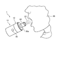
このメッシュ式ネブライザ1を使用する場合、予め、ユーザは、上述の手順で薬液パック20を装着する。そして、図7に示すように、ユーザは、ホルダ部材30の上面30aに設けられた開口部30oに、例えばマウスピース80を着脱可能に装着する。なお、マウスピース80に代えて、ユーザ99の顔を覆うような吸入マスクを装着してもよい。
このメッシュ式ネブライザ1を使用する場合、予め、ユーザは、上述の手順で薬液パック20を装着する。そして、図7に示すように、ユーザは、ホルダ部材30の上面30aに設けられた開口部30oに、例えばマウスピース80を着脱可能に装着する。なお、マウスピース80に代えて、ユーザ99の顔を覆うような吸入マスクを装着してもよい。
図7中に示すように、ユーザがメッシュ式ネブライザ1を少しだけ手前に傾けると、図2Bの第1領域にある薬液23が薬液パック20の凹部17の底面24cに沿って、振動部40の振動面43上へ向けて供給される。つまり、振動面43とメッシュ部24aとの間に薬液が供給される。そして、ユーザが電源スイッチ50をオンすると、振動部40の超音波振動子41に駆動電圧が印加されて振動面43が振動される。これにより、メッシュ部24aを通して薬液23が霧化されて噴出する。
使用後には、本体10から薬液パック20が取り除かれて捨てられる。
このように、この発明のメッシュ式ネブライザ1は、使用する度に新たな薬液パック20を装着するので、メッシュ部24aを洗浄する必要がない。したがって、衛生的でありかつ噴霧効率を低下させることなしに、ユーザにとって手入れが簡単となる。さらに、使用する度に新しいメッシュ部24aを使用するため、衛生的でありかつ噴霧効率が低下することがない。
以上の実施形態は例示であり、この発明の範囲から離れることなく様々な変形が可能である。上述した複数の実施の形態は、それぞれ単独で成立し得るものであるが、実施の形態同士の組みあわせも可能である。また、異なる実施の形態の中の種々の特徴も、それぞれ単独で成立し得るものであるが、異なる実施の形態の中の特徴同士の組みあわせも可能である。
1 メッシュ式ネブライザ
10 本体
11 本体下部
12 本体上部
17 凹部
20 薬液パック
21 蓋部材
23 薬液
24 薬液収容部材
30 ホルダ部材
31 外周壁
33 第1ねじ要素
34 第2ねじ要素
40 振動部
41 超音波振動子
42 ホーン
43 振動面
50 電源スイッチ
61 操作部
62 報知部
63 制御部
64 発振周波数生成部
65 霧化部
80 マウスピース
100 昇降機構
10 本体
11 本体下部
12 本体上部
17 凹部
20 薬液パック
21 蓋部材
23 薬液
24 薬液収容部材
30 ホルダ部材
31 外周壁
33 第1ねじ要素
34 第2ねじ要素
40 振動部
41 超音波振動子
42 ホーン
43 振動面
50 電源スイッチ
61 操作部
62 報知部
63 制御部
64 発振周波数生成部
65 霧化部
80 マウスピース
100 昇降機構
Claims (6)
- メッシュ部を通して薬液を霧化して噴出するメッシュ式ネブライザであって、
振動面を有する振動部を備えた本体と、
上記本体に対して着脱可能に装着される薬液パックとを備え、
上記薬液パックは、
上記メッシュ部が形成された蓋部材と、
上記メッシュ部へ向かって開き上記蓋部材に覆われた凹部を有し、この凹部に上記振動面上へ向けて供給すべき薬液が収容された薬液収容部材とを備え、
上記薬液収容部材の上記凹部の底面のうちの少なくとも上記振動面に対向すべき部分は伸展性を有する素材で形成され、
上記薬液パックが上記本体に装着されると、上記底面の上記伸展性を有する素材が伸びて、上記振動面が上記蓋部材の上記メッシュ部に接近するのを許容することを特徴とするメッシュ式ネブライザ。 - 請求項1に記載のメッシュ式ネブライザに装着される薬液パックであって、
上記メッシュ部が形成された蓋部材と、
上記メッシュ部へ向かって開き上記蓋部材に覆われた凹部を有し、この凹部に上記振動面上へ向けて供給すべき薬液が収容された薬液収容部材とを備え、
上記薬液収容部材の上記凹部の底面のうちの少なくとも上記振動面に対向すべき部分は伸展性を有する素材で形成されていることを特徴とする薬液パック。 - 請求項2に記載の薬液パックにおいて、
上記蓋部材は、上記薬液収容部材の上縁から外側に延伸して形成されたフランジ部を含み、
上記薬液パックが上記本体に装着されると、上記蓋部材のフランジ部が上記本体の上記振動面の周りを取り囲む内周壁の上縁で支持されることを特徴とする薬液パック。 - 請求項2または3に記載の薬液パックにおいて、
上記蓋部材は平坦な形状を有し、
上記凹部は、上記薬液が貯留される深い第1領域と、上記第1領域よりも浅い第2領域とを含み、
上記振動面に対向すべき上記薬液収容部材の上記凹部の底面は上記第2領域に配置されていることを特徴とする薬液パック。 - 請求項1に記載のメッシュ式ネブライザにおいて、
上記本体は、
上記振動面の周りを取り囲む内周壁と、
上記内周壁に対して同心で上記内周壁の周りに回転可能に配置された外周壁と、
上記内周壁と上記外周壁との間に介挿される筒状の周壁を有し、この周壁の一部に形成された開口部を通して上記薬液パックを受け入れて保持するホルダ部材とをさらに備え、
上記本体の上記外周壁が上記内周壁の周りに回転されるのに伴って、上記内周壁に対して上記ホルダ部材を上昇または下降させる昇降機構を備えたことを特徴とするメッシュ式ネブライザ。 - 請求項5に記載のメッシュ式ネブライザにおいて、
上記昇降機構は、上記ホルダ部材の外周面に設けられた第1ねじ要素と、上記第1ねじ要素と係合し得るように上記本体の上記外周壁の内面に形成された第2ねじ要素とを備えたことを特徴とするメッシュ式ネブライザ。
Priority Applications (3)
| Application Number | Priority Date | Filing Date | Title |
|---|---|---|---|
| CN201780055070.9A CN109689138B (zh) | 2016-09-20 | 2017-08-09 | 网眼式喷雾器和药液包 |
| DE112017004699.8T DE112017004699T5 (de) | 2016-09-20 | 2017-08-09 | Vernebler vom Netztyp und medizinische Flüssigkeitspackung |
| US16/280,080 US11318263B2 (en) | 2016-09-20 | 2019-02-20 | Mesh nebulizer and medicinal liquid pack |
Applications Claiming Priority (2)
| Application Number | Priority Date | Filing Date | Title |
|---|---|---|---|
| JP2016-183462 | 2016-09-20 | ||
| JP2016183462A JP6776761B2 (ja) | 2016-09-20 | 2016-09-20 | メッシュ式ネブライザおよび薬液パック |
Related Child Applications (1)
| Application Number | Title | Priority Date | Filing Date |
|---|---|---|---|
| US16/280,080 Continuation US11318263B2 (en) | 2016-09-20 | 2019-02-20 | Mesh nebulizer and medicinal liquid pack |
Publications (1)
| Publication Number | Publication Date |
|---|---|
| WO2018055940A1 true WO2018055940A1 (ja) | 2018-03-29 |
Family
ID=61689446
Family Applications (1)
| Application Number | Title | Priority Date | Filing Date |
|---|---|---|---|
| PCT/JP2017/028910 Ceased WO2018055940A1 (ja) | 2016-09-20 | 2017-08-09 | メッシュ式ネブライザおよび薬液パック |
Country Status (5)
| Country | Link |
|---|---|
| US (1) | US11318263B2 (ja) |
| JP (1) | JP6776761B2 (ja) |
| CN (1) | CN109689138B (ja) |
| DE (1) | DE112017004699T5 (ja) |
| WO (1) | WO2018055940A1 (ja) |
Families Citing this family (2)
| Publication number | Priority date | Publication date | Assignee | Title |
|---|---|---|---|---|
| CN110605194A (zh) * | 2019-10-29 | 2019-12-24 | 浙江大悦生物科技有限公司 | 一种倒流式可分次加注指定剂量雾化液的可储液电子雾化器 |
| US20240108830A1 (en) * | 2022-10-04 | 2024-04-04 | Blue Ocean Group, LLC | Compact Telescoping Spacer With Double-Barrel for Metered Dose Inhaler |
Citations (5)
| Publication number | Priority date | Publication date | Assignee | Title |
|---|---|---|---|---|
| JP2010119845A (ja) * | 2008-11-24 | 2010-06-03 | Ep Systems Sa Microflow Division | 噴霧器 |
| US20120259277A1 (en) * | 2011-04-06 | 2012-10-11 | Mystic Pharmaceuticals, Inc. | Medical devices for dispensing powders |
| US8353287B1 (en) * | 2006-04-20 | 2013-01-15 | Ric Investments, Llc | Disposable drug solution cup for an ultrasonic nebulizer |
| JP2013252261A (ja) * | 2012-06-06 | 2013-12-19 | Dainippon Printing Co Ltd | 噴霧デバイス用の液体カートリッジ、液体カートリッジパッケージ、噴霧デバイス及び噴霧デバイス用のメッシュ付容器 |
| JP2014004211A (ja) * | 2012-06-26 | 2014-01-16 | Omron Healthcare Co Ltd | 液体噴霧装置 |
Family Cites Families (16)
| Publication number | Priority date | Publication date | Assignee | Title |
|---|---|---|---|---|
| DE69210096T2 (de) * | 1991-05-27 | 1996-09-19 | Tdk Corp | Ultraschallzerstäuber |
| FR2705911B1 (fr) * | 1993-06-02 | 1995-08-11 | Oreal | Appareil de nébulisation piézoélectrique. |
| EP2165771B1 (en) * | 2000-10-05 | 2012-01-18 | Omron Healthcare Co., Ltd. | Liquid spray device |
| CN1810311A (zh) * | 2000-10-05 | 2006-08-02 | 欧姆龙健康医疗事业株式会社 | 液体雾化装置 |
| JP2003102837A (ja) * | 2001-09-28 | 2003-04-08 | Omron Corp | 霧化装置用吸入補助具およびこれを備えた霧化装置 |
| ATE491491T1 (de) * | 2004-06-09 | 2011-01-15 | Microflow Eng Sa | Verbessertes modulares flüssigkeitssprühsystem |
| JP5267245B2 (ja) * | 2009-03-17 | 2013-08-21 | オムロンヘルスケア株式会社 | ネブライザ、および、ネブライザに着脱可能な機能ユニット |
| JP5652790B2 (ja) * | 2011-09-22 | 2015-01-14 | オムロンヘルスケア株式会社 | 液体噴霧装置 |
| GB2500588B (en) * | 2012-03-24 | 2017-02-01 | Rhinocare Ltd | Systems and methods of hyperthermal treatment |
| JP2014004208A (ja) | 2012-06-26 | 2014-01-16 | Omron Healthcare Co Ltd | 液体噴霧装置 |
| CN103933645B (zh) * | 2013-01-21 | 2016-01-13 | 胡生彬 | 有效控制超微细雾化颗粒输出的医疗微网片雾化器 |
| RU2677011C2 (ru) * | 2013-05-17 | 2019-01-14 | Конинклейке Филипс Н.В. | Модуль доставки вещества |
| JP6401273B2 (ja) * | 2013-08-16 | 2018-10-10 | ベクチュラ・ゲーエムベーハー | 吸入装置用投与システム |
| TWI539978B (zh) * | 2013-09-13 | 2016-07-01 | 台達電子工業股份有限公司 | 微霧化裝置及其給藥室模組 |
| JP5928425B2 (ja) * | 2013-09-24 | 2016-06-01 | オムロンヘルスケア株式会社 | ネブライザ用メッシュ選定方法、装置、及びプログラム |
| EP3247435B1 (en) * | 2015-01-23 | 2021-03-10 | William Tan | Ultrasonic vaporizing element |
-
2016
- 2016-09-20 JP JP2016183462A patent/JP6776761B2/ja active Active
-
2017
- 2017-08-09 CN CN201780055070.9A patent/CN109689138B/zh active Active
- 2017-08-09 WO PCT/JP2017/028910 patent/WO2018055940A1/ja not_active Ceased
- 2017-08-09 DE DE112017004699.8T patent/DE112017004699T5/de active Pending
-
2019
- 2019-02-20 US US16/280,080 patent/US11318263B2/en active Active
Patent Citations (5)
| Publication number | Priority date | Publication date | Assignee | Title |
|---|---|---|---|---|
| US8353287B1 (en) * | 2006-04-20 | 2013-01-15 | Ric Investments, Llc | Disposable drug solution cup for an ultrasonic nebulizer |
| JP2010119845A (ja) * | 2008-11-24 | 2010-06-03 | Ep Systems Sa Microflow Division | 噴霧器 |
| US20120259277A1 (en) * | 2011-04-06 | 2012-10-11 | Mystic Pharmaceuticals, Inc. | Medical devices for dispensing powders |
| JP2013252261A (ja) * | 2012-06-06 | 2013-12-19 | Dainippon Printing Co Ltd | 噴霧デバイス用の液体カートリッジ、液体カートリッジパッケージ、噴霧デバイス及び噴霧デバイス用のメッシュ付容器 |
| JP2014004211A (ja) * | 2012-06-26 | 2014-01-16 | Omron Healthcare Co Ltd | 液体噴霧装置 |
Also Published As
| Publication number | Publication date |
|---|---|
| US20190175845A1 (en) | 2019-06-13 |
| DE112017004699T5 (de) | 2019-07-04 |
| US11318263B2 (en) | 2022-05-03 |
| CN109689138B (zh) | 2021-07-06 |
| JP6776761B2 (ja) | 2020-10-28 |
| JP2018046945A (ja) | 2018-03-29 |
| CN109689138A (zh) | 2019-04-26 |
Similar Documents
| Publication | Publication Date | Title |
|---|---|---|
| KR0152086B1 (ko) | 분배장치 | |
| KR102291016B1 (ko) | 살균 충전식 얼굴용 브러시 | |
| WO2018047508A1 (ja) | メッシュ式ネブライザ | |
| CN203029818U (zh) | 一种便携式喷雾器装置 | |
| TW201242627A (en) | Nebulizer for treating eyes | |
| KR20150085838A (ko) | 광 요법 스킨 장치 | |
| JP2018038668A5 (ja) | ||
| US10926045B2 (en) | Mesh nebulizer and replacement member | |
| JP2019076243A (ja) | メッシュ式ネブライザおよび交換部材 | |
| WO2018055940A1 (ja) | メッシュ式ネブライザおよび薬液パック | |
| JP2018046945A5 (ja) | ||
| JP2017202026A5 (ja) | ||
| TWM536948U (zh) | 微霧化裝置及微霧化器 | |
| JP7030771B2 (ja) | エアロゾル化装置及びエアロゾル薬物送達装置 | |
| ES2975768T3 (es) | Método y recipiente para limpiar la membrana de un nebulizador | |
| JP6701935B2 (ja) | メッシュ式ネブライザおよび交換セット | |
| JP2006006570A (ja) | 超音波オーラルケア用品 | |
| US20060253154A1 (en) | Teething device | |
| JP2019025196A (ja) | 噴霧式美容器 | |
| KR200333427Y1 (ko) | 구강 세정장치 | |
| TWM528175U (zh) | 便攜式噴霧器 | |
| KR100985761B1 (ko) | 초음파소자 일체형 메쉬와 실리콘 홀더와 약제통의 결합구조 | |
| KR100591522B1 (ko) | 화장용 파우더 용기 | |
| BR112020007587B1 (pt) | Membro de substituição, e, nebulizador do tipo malha | |
| JP2019051217A (ja) | メッシュ式ネブライザ |
Legal Events
| Date | Code | Title | Description |
|---|---|---|---|
| 121 | Ep: the epo has been informed by wipo that ep was designated in this application |
Ref document number: 17852721 Country of ref document: EP Kind code of ref document: A1 |
|
| 122 | Ep: pct application non-entry in european phase |
Ref document number: 17852721 Country of ref document: EP Kind code of ref document: A1 |