WO2018055867A1 - X線位相差撮像装置用回折格子、x線位相差撮像装置用x線発生ユニット、x線位相差撮像装置 - Google Patents
X線位相差撮像装置用回折格子、x線位相差撮像装置用x線発生ユニット、x線位相差撮像装置 Download PDFInfo
- Publication number
- WO2018055867A1 WO2018055867A1 PCT/JP2017/024109 JP2017024109W WO2018055867A1 WO 2018055867 A1 WO2018055867 A1 WO 2018055867A1 JP 2017024109 W JP2017024109 W JP 2017024109W WO 2018055867 A1 WO2018055867 A1 WO 2018055867A1
- Authority
- WO
- WIPO (PCT)
- Prior art keywords
- grating
- ray
- phase difference
- lattice
- period
- Prior art date
- Legal status (The legal status is an assumption and is not a legal conclusion. Google has not performed a legal analysis and makes no representation as to the accuracy of the status listed.)
- Ceased
Links
Images



Classifications
-
- A—HUMAN NECESSITIES
- A61—MEDICAL OR VETERINARY SCIENCE; HYGIENE
- A61B—DIAGNOSIS; SURGERY; IDENTIFICATION
- A61B6/00—Apparatus or devices for radiation diagnosis; Apparatus or devices for radiation diagnosis combined with radiation therapy equipment
-
- A—HUMAN NECESSITIES
- A61—MEDICAL OR VETERINARY SCIENCE; HYGIENE
- A61B—DIAGNOSIS; SURGERY; IDENTIFICATION
- A61B6/00—Apparatus or devices for radiation diagnosis; Apparatus or devices for radiation diagnosis combined with radiation therapy equipment
- A61B6/06—Diaphragms
-
- G—PHYSICS
- G01—MEASURING; TESTING
- G01N—INVESTIGATING OR ANALYSING MATERIALS BY DETERMINING THEIR CHEMICAL OR PHYSICAL PROPERTIES
- G01N23/00—Investigating or analysing materials by the use of wave or particle radiation, e.g. X-rays or neutrons, not covered by groups G01N3/00 – G01N17/00, G01N21/00 or G01N22/00
- G01N23/02—Investigating or analysing materials by the use of wave or particle radiation, e.g. X-rays or neutrons, not covered by groups G01N3/00 – G01N17/00, G01N21/00 or G01N22/00 by transmitting the radiation through the material
- G01N23/04—Investigating or analysing materials by the use of wave or particle radiation, e.g. X-rays or neutrons, not covered by groups G01N3/00 – G01N17/00, G01N21/00 or G01N22/00 by transmitting the radiation through the material and forming images of the material
-
- G—PHYSICS
- G01—MEASURING; TESTING
- G01T—MEASUREMENT OF NUCLEAR OR X-RADIATION
- G01T7/00—Details of radiation-measuring instruments
Definitions
- the present invention relates to a diffraction grating for an X-ray phase difference imaging apparatus, an X-ray generation unit for an X-ray phase difference imaging apparatus including the diffraction grating for the X-ray phase difference imaging apparatus, and an X-ray phase difference imaging apparatus.
- JP 2012-16370 A Conventionally, for example, an X-ray phase difference imaging apparatus as disclosed in JP 2012-16370 A is known.
- Japanese Unexamined Patent Application Publication No. 2012-16370 discloses an X-ray imaging apparatus (X-ray phase difference imaging apparatus) that images the inside of a subject using the phase difference of X-rays that have passed through the subject.
- This X-ray imaging device uses X-ray phase difference instead of X-ray absorption to image the inside of the subject, thereby imaging light element objects and soft tissue that are difficult to absorb X-rays. It is configured to be able to.
- An X-ray imaging apparatus disclosed in Japanese Patent Application Laid-Open No. 2012-16370 includes an X-ray generator that emits radial X-rays, an X-ray source including a multi-slit, a grating, and an X-ray image detector. Low interferometer.
- the X-ray generator, the multi-slit, the grating (diffraction grating), and the X-ray image detector are arranged in this order in the irradiation axis direction of the X-ray source.
- Japanese Patent Laid-Open No. 2012-16370 discloses a conventional example in which another grating is arranged in front of the X-ray image detector in addition to the above configuration. In this conventional example, imaging by the X-ray image detector is facilitated by detecting X-rays that have passed through a grating arranged in front of the X-ray image detector as moire interference fringes.
- the grating disposed in front of the multi-slit and the X-ray image detector is an absorption grating that absorbs X-rays in the grating part, in order to reliably absorb X-rays in the grating part, It is required to increase the thickness. Furthermore, in the absorption grating, it is necessary to reduce the grating gap (transmission part) in order to increase the spatial coherence. As a result, particularly in an absorption grating, it is required to increase the aspect ratio (the thickness of the absorption portion with respect to the grating period).
- the multi-slit, the grating, and the grating arranged in front of the X-ray image detector are all constituted by a general one-stage grating. it is conceivable that.
- the present invention has been made to solve the above-described problems, and one object of the present invention is to provide a diffraction grating for an X-ray phase difference imaging apparatus capable of easily increasing an aspect ratio, An X-ray generation unit for an X-ray phase difference imaging apparatus using the diffraction grating for an X-ray phase difference imaging apparatus, and an X-ray phase difference imaging apparatus using the diffraction grating for the X-ray phase difference imaging apparatus are provided. .
- a diffraction grating for an X-ray phase difference imaging apparatus includes a first grating including a plurality of first grating portions formed at a first grating period, A plurality of second grating portions formed with a second grating period different from the grating period, and stacked on the first grating so that a space between the first grating parts and a space between the second grating parts are connected to each other; Two grids.
- a first grating including a plurality of first grating portions formed with a first grating period, a first grating period are stacked with a second grating including a plurality of second grating parts formed with different second grating periods.
- the first grating period and the second grating period are different, the first grating part and the second grating part do not have to be precisely aligned when the first grating and the second grating are stacked.
- the first grating part and the second grating part sufficiently overlap in the stacking direction of the first grating and the second grating, and the first A portion where the space between the first grating portions and the space between the second grating portions are sufficiently connected can be formed in the diffraction grating for an X-ray phase difference imaging apparatus.
- the first grating portion and the second grating portion can be overlapped with each other in a specific direction among the directions inclined with respect to each other, and the space between the first grating portions and the space between the second grating portions can be sufficiently connected. be able to.
- the first lattice portion and the second lattice portion sufficiently overlap, and the space between the first lattice portion and the space between the second lattice portions is It can be connected enough.
- the space between the first grating portions is appropriately adjusted by appropriately adjusting the incident angle of X-rays to the diffraction grating for the X-ray phase difference imaging apparatus (the angle at which the X-rays spread radially).
- the first grating portion and the second grating portion are inclined with respect to the stacking direction and the stacking direction.
- the aspect ratio can be substantially increased by overlapping in the direction.
- the first grating is located closer to the X-ray generation unit that radiates the generated X-rays radially than the second grating.
- the center between the second grating parts substantially coincide with each other, and the distance between the center between the first grating parts and the center between the second grating parts increases as the distance from the vicinity of the center position increases.
- a second lattice is laminated.
- the X-rays irradiated radially are incident between the first grating units at a certain incident angle with respect to the optical axis.
- the X-ray incident angle increases as the distance between the first grating portions increases from the center position. Therefore, in the present invention, the first grating and the second grating are stacked so that the deviation between the center between the first grating parts and the center between the second grating parts increases as the distance from the center position increases.
- lattice parts can be enlarged corresponding to the incident angle of X-ray becoming large as it distances from a center position. .
- X-rays incident with an incident angle are not only between the first grating parts but also between the second grating parts. Can be made to pass easily. As a result, it is possible to suppress a decrease in the dose of X-rays that pass through the diffraction grating for an X-ray phase difference imaging apparatus, and it is possible to suppress a narrowing of the visual field range.
- the first grating portion is arranged with the first grating period
- the second grating portion is arranged with the second grating period different from the first grating period.
- the center between the first grating part and the center between the second grating part substantially coincide with each other in the vicinity of the center position, and the center between the first grating part and the center between the second grating parts as the distance from the center position increases.
- the first grating and the second grating are stacked so that the deviation of the first and second gratings increases.
- the center position and the optical axis of an X-ray generation part are substantially made.
- the X-ray dose that has passed through the diffraction grating for an X-ray phase difference imaging apparatus can be made substantially symmetrical with respect to the center position.
- the diffraction grating for an X-ray phase difference imaging apparatus is used as a multi-slit of the X-ray phase difference imaging apparatus, a more accurate self-image can be obtained using the X-rays that have passed through the multi-slit.
- the diffraction grating for an X-ray phase difference imaging apparatus is used as an absorption grating of the X-ray phase difference imaging apparatus, more accurate moire interference fringes can be obtained by using the X-rays that have passed through the absorption grating. .
- the second grating period of the second grating is larger than the first grating period of the first grating.
- the first grating and the second grating are stacked in contact with each other, and the second grating period P k + of the second grating is obtained. 1 satisfies the following formula (1) with respect to the first grating period P k of the first grating.
- L k is the distance between the first lattice and the X-ray generation unit
- H k is the length of the first lattice unit in the stacking direction of the first and second lattices.
- the relationship between the first grating period and the second grating period can be approximated to a similar relation of triangles, so that the first grating part passes between the first grating parts even at positions away from the center position. X-rays can be reliably passed between the second grating portions.
- the first grating and the second grating are stacked in the optical axis direction of the X-ray generation unit. If comprised in this way, the X-ray
- the X-ray phase difference imaging device X-ray generation unit is directed to the X-ray phase difference imaging device diffraction grating and the X-ray phase difference imaging device diffraction grating according to the first aspect.
- An X-ray generation unit that emits X-rays.
- the diffraction for an X-ray phase difference imaging apparatus having high spatial coherence can be obtained by using a diffraction grating for an X-ray phase difference imaging apparatus having a large aspect ratio while sufficiently transmitting X-rays. Since a grating can be obtained, it is possible to obtain an X-ray generation unit for an X-ray phase difference imaging apparatus that can irradiate X-rays so that clear interference fringes can be obtained.
- the X-ray phase difference imaging apparatus is irradiated from the X-ray phase difference imaging apparatus X-ray generation unit and the X-ray phase difference imaging apparatus X-ray generation unit according to the second aspect.
- a phase grating for forming a self-image by X-rays and a detection unit for detecting X-rays that have passed through the phase grating are provided. If comprised in this way, the X-ray phase difference imaging device which can obtain a clear interference fringe can be obtained.
- An X-ray phase difference imaging apparatus forms a self-image by an X-ray generation unit including an X-ray generation unit that irradiates X-rays and an X-ray irradiated from the X-ray generation unit.
- X-ray phase difference imaging which can obtain a clear moire interference fringe by using the diffraction grating for X-ray phase difference imaging devices with a large aspect ratio while transmitting X-rays sufficiently.
- a device can be obtained.
- the diffraction grating for an X-ray phase difference imaging device capable of easily increasing the aspect ratio, and the X-ray phase difference imaging using the diffraction grating for the X-ray phase difference imaging device.
- An X-ray phase difference imaging apparatus using the apparatus X-ray generation unit and the diffraction grating for the X-ray phase difference imaging apparatus can be provided.
- FIG. 1 is a diagram illustrating an overall configuration of an X-ray phase difference imaging apparatus according to an embodiment of the present invention.
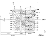
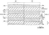
- FIG. 2 is a cross-sectional view of a multi-slit taken along line 200-200 in FIG. It is sectional drawing which expanded and showed a part of FIG. In the multi slit of one embodiment of the present invention, it is a figure for explaining the relation between the 1st lattice period and the 2nd lattice period.
- FIG. 3 is a cross-sectional view of the absorption grating taken along line 300-300 in FIG.
- the X-ray phase difference imaging apparatus 100 is an apparatus that images the inside of the subject T using the phase difference of the X-rays that have passed through the subject T, as shown in FIG.
- the X-ray phase difference imaging apparatus 100 is an apparatus that images the inside of the subject T using the Talbot effect.
- the X-ray phase difference imaging apparatus 100 can be used for imaging the inside of the subject T as a living body, for example, in medical applications. Further, the X-ray phase difference imaging apparatus 100 can be used for imaging the inside of the subject T as an object, for example, for nondestructive inspection.
- the X-ray phase difference imaging apparatus 100 includes an X-ray generation unit 1, a diffraction grating 2, an absorption grating 3, and a detection unit 4.
- the X-ray generation unit 1 includes an X-ray generation unit 10 and a multi slit 20.
- the X-ray phase difference imaging apparatus 100 uses the X-ray generation unit 1 (the X-ray generation unit 10 and the multi-slit 20), the diffraction grating 2, the absorption grating 3, and the detection unit 4 to X-ray imaging is performed by a low (Talbot-Lau) interferometer.
- the X-ray generation unit 1 is an example of the “X-ray generation unit for an X-ray phase difference imaging device” in the claims, and the multi-slit 20 and the absorption grating 3 are the “X-ray positions” in the claims. It is an example of a "diffractive grating for phase difference imaging devices.”
- the diffraction grating 2 is an example of the “phase grating” in the claims.
- the X-ray generation unit 10, the multi-slit 20, the diffraction grating 2, the absorption grating 3, and the detection unit 4 are arranged in this order in the optical axis direction (Z direction) that is the direction in which X-rays are emitted. Is arranged. Further, the multi-slit 20, the diffraction grating 2, and the absorption grating 3 are each formed so as to spread in a plane direction orthogonal to the optical axis direction, and are arranged so that the optical axis direction is the thickness direction. Yes.
- the optical axis direction of the X-ray is the Z direction
- the directions orthogonal to each other in the plane orthogonal to the Z direction are the X direction and the Y direction, respectively.
- the X-ray generation unit 10 of the X-ray generation unit 1 generates X-rays by applying a high voltage, and radiates the generated X-rays radially (cone beam shape) toward the optical axis direction. It is configured as follows. That is, the X-ray generation unit 10 irradiates X-rays so as to spread concentrically around the optical axis.
- the multi-slit 20 of the X-ray generation unit 1 is provided in order to increase the spatial coherence of X-rays emitted from the X-ray generation unit 10 due to the Lau effect.
- the multi-slit 20 is an absorption grating as a kind of diffraction grating.
- X-rays radiated from the X-ray generator 10 are incident on the multi-slit 20. That is, in the multi-slit 20, X-rays are incident in a direction (Z direction) orthogonal to the surface of the multi-slit 20 at a position substantially coincident with the optical axis of the X-ray generation unit 10, while the X-ray generation unit 10.
- X-rays are incident (obliquely entered) obliquely with respect to the Z direction at positions away from the optical axis.
- the detailed configuration of the multi slit 20 will be described later.
- the diffraction grating 2 is a phase grating as a kind of diffraction grating that changes the phase of X-rays passing therethrough.
- the diffraction grating 2 has a plurality of slits 2a arranged at a period (pitch) in the X direction orthogonal to the Z direction. Each slit 2a is formed to extend in the Y direction orthogonal to the Z direction.
- the diffraction grating 2 is irradiated with X-rays that have passed through the multi slit 20.
- the diffraction grating 2 is provided to form a self image. Specifically, when X-rays having spatial coherence pass through the diffraction grating 2 in which the slits 2a are formed, an image of the grating (self-image) is located at a predetermined distance (Talbot distance) from the grating. ) Is formed. This is called the Talbot effect.
- the self-image is an interference fringe generated by X-ray interference.
- the self-image of the diffraction grating 2 due to the Talbot effect can be more reliably formed by providing the multi-slit 20 to enhance the coherence of X-rays.
- the absorption grating 3 is provided to interfere with the self-image of the diffraction grating 2 to form moire fringes.
- the absorption grating 3 is an absorption grating as a kind of diffraction grating. Further, the absorption grating 3 is designed to be disposed at a position separated from the diffraction grating 2 by a Talbot distance. Furthermore, radial X-rays that have passed through the diffraction grating 2 are incident on the absorption grating 3.
- X-rays are incident in a direction (Z direction) orthogonal to the surface of the absorption grating 3 at a position substantially coincident with the optical axis of the X-ray generation unit 10, while the X-ray generation unit 10.
- X-rays are incident (obliquely entered) obliquely with respect to the Z direction at positions away from the optical axis.
- the detailed configuration of the absorption grating 3 will be described later.
- the subject T when imaging the subject T, the subject T is disposed between the X-ray generation unit 1 and the diffraction grating 2. In this case, X-rays that have passed through the subject T are applied to the absorption grating 3.
- the subject T may be arranged between the diffraction grating 2 and the absorption grating 3.
- the detection unit 4 is configured to detect X-rays and convert the detected X-rays into electric signals (detection signals).
- the detection unit 4 is configured to output a detection signal to a control unit (not shown).
- the detection unit 4 is, for example, an FPD (Flat Panel Detector).
- the detection unit 4 includes a plurality of detection elements (not shown). The plurality of detection elements are arranged side by side in the X direction and the Y direction at a predetermined period (pitch).
- the period of the detection element is larger than the period of the self-image of the diffraction grating 2.
- the X-ray phase difference imaging apparatus 100 interferes with the self-image of the diffraction grating 2 to form moire fringes.
- the absorption grating 3 is provided, and the moire fringes due to the superposition of the self-image of the diffraction grating 2 and the absorption grating 3 are detected by the detection unit 4.
- the period of the moire fringes due to the superposition of the self-image of the diffraction grating 2 and the absorption grating 3 is sufficiently larger than the period of the detection element.
- the X-ray phase difference imaging apparatus 100 is configured so that the moire fringes due to the superposition of the self-image of the diffraction grating 2 and the absorption grating 3 can be easily detected by the detection unit 4. Yes.
- the multi-slit 20 of the present embodiment includes a substrate 21 made of silicon, a first grating 22 formed on the substrate 21, and a second grating 23 formed on the first grating 22. Is included.
- the substrate 21, the first grating 22, and the second grating 23 are stacked in the optical axis direction (Z direction). At this time, the substrate 21 is disposed closest to the X-ray generator 10 in the multi-slit 20, and the second grating 23 is disposed closest to the X-ray generator 10 in the multi-slit 20. Has been.
- the substrate 21 is disposed on substantially the entire surface direction orthogonal to the optical axis direction of the multi-slit 20, and mainly transmits X-rays.
- the first grating 22 has a plurality of first grating portions 22a made of Au that absorbs X-rays.
- the plurality of first grating portion 22a are arranged in the first grating period P 1 in the X direction orthogonal to the Z direction.
- the first lattice portion 22a is formed so as to extend in the Y direction orthogonal to the Z direction.
- the first grating 22 has a plurality of first transmission portions 22b made of a resist that transmits X-rays.
- the plurality of first transmission portions 22b are disposed between the first lattice portions 22a. That is, the plurality of first transmission parts 22b are arranged in the X direction with the first grating period P 1 .
- the first transmission part 22b is formed to extend in the Y direction orthogonal to the Z direction.
- the length (width) in the X direction of the first transmission part 22b is substantially equal to the length (width) in the X direction of the first grating part 22a. That is, the length of the first grating portion 22a in the X direction and the length of the first transmission portion 22b in the X direction are both P 1/2 .
- the second grating 23 has a plurality of second grating portions 23a made of Au that absorbs X-rays.
- the plurality of second grating portion 23a are arranged in the second grating period P 2 in the X direction orthogonal to the Z direction.
- the second lattice portion 23a is formed to extend in the Y direction orthogonal to the Z direction.
- the second grating 23 has a plurality of second transmission parts 23b made of a resist that transmits X-rays.
- the plurality of second transmission parts 23b are arranged between the second grating parts 23a. That is, a plurality of second transmitting portion 23b are arranged in the second grating period P 2 in the X direction. Further, the second transmission part 23b is formed to extend in the Y direction orthogonal to the Z direction.
- the length (width) in the X direction of the second transmission part 23b is substantially equal to the length (width) in the X direction of the second grating part 23a.
- the multi slit 20 is configured so that the space of the first transmission part 22b and the space of the second transmission part 23b are connected.
- the second grating period P 2 of the second grating part 23a is greater than the first grating period P 1 of the first grating part 22a (first transmission part 22b). It is set to be large. Thereby, the first grating 22 and the second grating 23 are laminated so that the first grating part 22a and the second grating part 23a are displaced in the X direction. As a result, as shown in FIG. 3, the center Oa of the first transmission part 22b and the center Ob of the second transmission part 23b are
- ( P 2 ⁇ P 1 ) for each grating period. Only shifts in the X direction.
- a position where the center Oa of the first transmission part 22b and the center Ob of the second transmission part 23b substantially coincide with each other is arranged on the center position O in the X direction of the multi-slit 20 arranged on the optical axis.
- the multi-slit 20 is disposed in the X-ray phase difference imaging apparatus 100.
- the deviation G0 (not shown) between the center Oa 0 of the first transmission part 22b at the center position O and the center Ob 0 of the second transmission part 23b is less than (P 2 ⁇ P 1 ) and is sufficiently small.
- the second grating period P 2 is larger than the first grating period P 1 , the center Oa 1 of the first transmission part 22 b and the second transmission part 23 b are located at a position shifted by one period from the center position O.
- the multi slit 20 can be formed.
- the second grating period P 2 (P k + 1 ) is formed so as to satisfy the following expression (1) with respect to the first grating period P 1 (P k ).
- “L k ” is the distance between the first grating 22 and the X-ray generation unit 10
- “H k ” is the length of the first grating unit 22 a (first transmission unit 22 b) in the Z direction. is there.
- the second grating period P 2 (P k + 1 ) is preferably a value in the vicinity of the following formula (2) with respect to the first grating period P 1 (P k ).
- P k + 1 ((L k + H k ) / L k ) ⁇ P k (2)
- the X-ray generator 10 is sufficiently separated from the multi-slit 12 and the X-ray generator 10 is a point light source. Further, the angle formed with respect to the optical axis of the X-rays incident on the a-th first transmitting portion 22b from first transparent portion 22b on one side in the X direction of the center position O and a theta a. In this case, the geometric condition shown in FIG. 4 may be satisfied so that the X-rays are sufficiently incident also on the second transmission portion 23b of the second grating 23.
- FIG. 4 shows a triangle ABC and a triangle ADE similar to the triangle ABC.
- the positions of the vertices A, B, and C of the triangle ABC correspond to the position of the X-ray generation unit 10, the position of the first transmission part 22b at the center position O, and the position of the second transmission part 23b at the center position O, respectively.
- the positions of the vertices D and E of the triangle ADE respectively correspond to the position of the a-th first transmission part 22b and the position of the a-th second transmission part 23b.
- the first lattice period P 1 (P k ) and the second lattice period are derived from the similar relation of triangles in which the ratio of the line segment AB to the line segment BC matches the ratio of the line segment AD to the line segment DE. Since the ratio with P 2 (P k + 1 ) matches the ratio between the distance R and the period d2, the following equation (3) can be derived.
- L k : aP k (L k + H k ): aP k + 1 (3)
- equation (2) is derived. Even if there is a certain margin, X-rays can be made sufficiently incident on the second transmission part 23b, so that the allowance is considered in equation (2), so that equation (1) is derived. It is burned.
- the multi-slit 20 is configured so as to satisfy the condition of the above formula (1) or formula (2), and the X-ray generation unit 10 is arranged to cope with the oblique insertion of the X-rays, and It is possible to obtain the multi slit 20 capable of increasing the aspect ratio.
- the X-rays incident on the first grating portion 22a are sufficiently absorbed by the first grating portion 22a and the second grating portion 23a appropriately shifted with respect to the first grating portion 22a. It is possible to absorb.
- the multi-slit 20 is formed by forming the first grating 22 on the substrate 21 and then forming the second grating 23 on the first grating 22.
- a resist is left in the position corresponding to the 1st transmission part 22b, and it respond
- the resist is removed at the position to be formed to form a groove.
- lattice part 22a is formed by giving Au plating so that the groove
- the multi-slit 20 is created by forming the second grating 23 in the same process as the process of forming the first grating 22.
- the deviation G between the center Oa of the first transmission portion 22b and the center Ob of the second transmission portion 23b is less than (P 2 ⁇ P 1 ) at any position in the X direction. Since the center Oa of the first transmission part 22b and the center Ob of the second transmission part 23b can be substantially coincided with each other, the position of the second grating part 23a and the position of the second transmission part 23b of the second grating 23 Are not strictly matched to the position of the first grating portion 22a and the position of the first transmitting portion 22b of the first grating 22, respectively. Thereby, the multi slit 20 can be easily created.
- the position where the center Oa of the first transmission part 22b and the center Ob of the second transmission part 23b substantially coincide with each other is set as the center position O of the multi-slit 20, and the center position O is the optical axis of the X-ray generation unit 10.
- the multi-slit 20 is arranged in the X-ray phase difference imaging apparatus 100 so as to substantially coincide with.
- the absorption grating 3 of the present embodiment is the same as the multi-slit 20 except that the first grating period Q 1 (Q k ) and the second grating period Q 2 (Q k + 1 ) are different. It has the composition of. That is, the absorption grating 3 has a configuration in which the substrate 31, the first grating 32, and the second grating 33 are stacked in the optical axis direction (Z direction). At this time, the substrate 31 is arranged closest to the X-ray generation unit 1 in the absorption grating 3, and the second grating 33 is arranged closest to the X-ray generation unit 1 in the absorption grating 3. Has been.
- lattice 32 has the some 1st grating
- a plurality of first grating portions 32a and a plurality of first transparent portion 32b is arranged in the first grating period Q 1 in the X direction.
- the second grating 33 includes a plurality of second grating parts 33a and a plurality of second transmission parts 33b arranged between the second grating parts 33a.
- the plurality of second grating portions 33a and a plurality of second transmitting portion 33b are arranged in the second grating period Q 2 in the X direction.
- the absorption grating 3 is configured so that the space of the first transmission part 32b and the space of the second transmission part 33b are connected.
- the second grating period Q 2 of the second grating part 33a (second transmitting part 33b) is greater than the first grating period Q 1 of the first grating part 32a (first transmitting part 32b). It is set to be large. Thereby, the first grating 32 and the second grating 33 are laminated so that the first grating part 32a and the second grating part 33a are displaced in the X direction. As a result, similarly to the multi-slit 20, the center of the first transmission part 32b and the center of the second transmission part 33b are equal to
- ( Q 2 ⁇ Q 1 ) for each grating period. Deviation in direction.
- the shift between the center of the first transmission part 32b and the center of the second transmission part 33b at any position in the X direction is (Q 2 ⁇ Q 1 ), and the center of the first transmission part 32b and the center of the second transmission part 33b can be substantially matched.
- the absorption grating 3 is configured such that the deviation between the center of the first transmission part 22b and the center of the second transmission part 23b increases as the distance from the vicinity of the center position O increases.
- the second grating period Q 2 (Q k + 1 ) is expressed by the following equation (4) with respect to the first grating period Q 1 (Q k ). It is formed to satisfy.
- M k is the distance between the first grating 32 and the multi-slit 20
- I k is the length of the first grating part 32a (first transmission part 32b) in the Z direction.
- the second grating period Q 2 (Q k + 1 ) is preferably a value in the vicinity of the following equation (5) with respect to the first grating period Q 1 (Q k ).
- Q k + 1 ((M k + I k ) / M k ) ⁇ Q k (5)
- the absorption grating 3 is configured so as to satisfy the condition of the above-described formula (4) or formula (5), and the X-ray generation unit 1 is arranged to cope with the oblique insertion of X-rays, and It is possible to obtain the absorption grating 3 capable of increasing the aspect ratio.
- the first grating 22 comprising a plurality of first grating portion 22a formed by the first grating period P k, first is different from the first grating period P k
- a second grating 23 including a plurality of second grating portions 23a formed with two grating periods P k + 1 is stacked.
- a portion where the first lattice portion 22a and the second lattice portion 23a sufficiently overlap each other and a portion where the space of the first transmission portion 22b and the space of the second transmission portion 23b are sufficiently connected are formed. can do. Further, even if the first grating portion 22a and the second grating portion 23a do not sufficiently overlap in the stacking direction (where the first grating portion 22a and the second grating portion 23a are displaced in the Z direction).
- the first grating portion 22a and the second grating portion 23a can be overlapped in a specific direction among the directions inclined with respect to the stacking direction, and the space of the first transmission portion 22b and the second transmission portion 23b can be overlapped.
- the space can be fully connected.
- the first grating portion 22a and the second grating portion 23a sufficiently overlap, and the space of the first transmitting portion 22b and the space of the second transmitting portion 23b. And can be connected enough.
- the space of the first transmission part 22b and the second transmission part are appropriately adjusted by appropriately adjusting the incident angle of X-rays to the multi-slit 20 (the angle at which the X-rays spread radially).
- the aspect ratio is substantially increased by overlapping the first grating portion 22a and the second grating portion 23a in the stacking direction and the direction inclined with respect to the stacking direction. The ratio can be increased. As a result, it is possible to obtain the multi-slit 20 capable of easily increasing the aspect ratio while sufficiently transmitting X-rays.
- the multi-slit 20 having a large aspect ratio for the X-ray generation unit 1 while sufficiently transmitting X-rays it is possible to obtain the multi-slit 20 having high spatial coherence.
- An X-ray generation unit 1 capable of emitting X-rays so that fringes can be obtained can be obtained, and an X-ray phase difference imaging apparatus 100 capable of obtaining clear interference fringes can be obtained. be able to.
- the absorption grating 3 a first grating 32 comprising a plurality of first grating portion 32a formed by the first grating period Q k, the first grating period Q k A second grating 33 including a plurality of second grating portions 33a formed with different second grating periods Q k + 1 is stacked.
- the absorption grating 3 capable of easily increasing the aspect ratio while sufficiently transmitting X-rays.
- the X-ray phase difference imaging apparatus 100 capable of obtaining a clear moire interference fringe can be obtained by using the absorption grating 3 having a large aspect ratio while sufficiently transmitting X-rays.
- the first grating 22 is positioned closer to the X-ray generator 10 that radiates the generated X-rays radially than the second grating 23. Deploy. Further, the center position O in the X direction perpendicular to the stacking direction (optical axis direction) of the first grating 22 and the second grating 23 and perpendicular to the Y direction in which the first grating part 22a and the second grating part 23a extend.
- the center Oa of the first transmission part 22b and the center Ob of the second transmission part 23b substantially coincide with each other in the vicinity, and the center Oa of the first transmission part 22b and the center of the second transmission part 23b as the distance from the vicinity of the center position O increases.
- the first grating 22 and the second grating 23 are stacked so that the deviation from Ob becomes large. Thereby, the deviation between the center Oa of the first transmission part 22b and the center Ob of the second transmission part 23b can be increased corresponding to the increase in the incident angle of X-rays as the distance from the center position O increases.
- the first transmission part 22b is arranged with the first grating period Pk
- the second transmission part 23b is different from the first grating period Pk .
- the center Oa of the first transmission part 22b and the center Ob of the second transmission part 23b substantially coincide with each other in the vicinity of the center position O, and as the distance from the vicinity of the center position O increases,
- the first grating 22 and the second grating 23 are stacked so that the deviation between the center Oa of the first transmission part 22b and the center Ob of the second transmission part 23b becomes large.
- the first transmission part 22b and the second transmission part 23b are arranged so as to be substantially symmetric with respect to the center position O, so that the center position O and the optical axis of the X-ray generation part 10 substantially coincide.
- the X-ray dose that has passed through the multi-slit 20 can be made substantially symmetrical with respect to the center position O.
- a more accurate self-image can be obtained using the X-rays that have passed through the multi-slit 20.
- the first grating 32 is positioned closer to the X-ray generation unit 1 that radiates the generated X-rays radially than the second grating 33. Deploy. Further, the center position O in the X direction orthogonal to the stacking direction (optical axis direction) of the first grating 32 and the second grating 33 and orthogonal to the Y direction in which the first grating part 32a and the second grating part 33a extend.
- the center of the first transmission part 32b and the center of the second transmission part 33b substantially coincide with each other, and the distance between the center of the first transmission part 32b and the center of the second transmission part 33b increases as the distance from the vicinity of the center position O increases.
- the first grating 32 and the second grating 33 are stacked so that the height becomes larger. Thereby, it can suppress that the dose of the X-ray which passes the absorption grating 3 falls, and can suppress that a visual field range (detection range in the detection part 4) becomes narrow.
- the absorption grating 3 the first transmitting portion 32b is arranged at a first grating period Q k, second the second transmitting portion 33b is different from the first grating period Q k
- the center of the first transmission part 32b and the center of the second transmission part 33b substantially coincide with each other in the vicinity of the center position O, and as the distance from the vicinity of the center position O increases, the first The first grating 32 and the second grating 33 are stacked so that the deviation between the center of the transmission part 32b and the center of the second transmission part 33b becomes large.
- the second grating period P k + 1 of the second grating 23 is made larger than the first grating period P k of the first grating 22. Accordingly, as the distance from the center position O increases, the difference between the center Oa of the first transmission part 22b and the center Ob of the second transmission part 23b is the difference between the second grating period P k + 1 and the first grating period P k. Therefore, as the distance from the center position O increases, the deviation between the center Oa of the first transmission part 22b and the center Ob of the second transmission part 23b can be easily increased.
- the second grating period Q k + 1 of the second grating 33 is made larger than the first grating period Q k of the first grating 32.
- the first grating 22 and the second grating 23 are stacked in contact with each other, and the second grating period P k + of the second grating 23. 1 is configured to satisfy the above formula (1) with respect to the first grating period P k of the first grating 22.
- the relationship between the first grating period P k and the second grating period P k + 1 can be approximated to a similar relation of triangles, so that the first transmission part can be obtained even at a position away from the center position O.
- the X-rays that have passed through 22b can be reliably passed through also in the second transmission part 23b.
- the first grating 32 and the second grating 33 are stacked in contact with each other, and the second grating period Q k + 1 of the second grating 33 is set to the first grating 32.
- the grating period Q k is configured to satisfy the above formula (4).
- the first grating 22 and the second grating 23 are stacked in the optical axis direction (Z direction) of the X-ray generation unit 10.
- the X-ray can be efficiently incident on the multi-slit 20 by making the stacking direction of the first grating 22 and the second grating 23 substantially coincide with the optical axis of the X-ray generation unit 10.
- the first grating 32 and the second grating 33 are stacked in the optical axis direction (Z direction) of the X-ray generation unit 10. If comprised in this way, similarly to the multi slit 20, X-rays can be efficiently incident on the absorption grating 3.
- the absorption grating 3 in which the first grating 32 and the second grating 33 having different values are stacked is shown, the present invention is not limited to this.
- the structure of the diffraction grating of the present invention may be a structure in which a first grating and a second grating having different grating periods are stacked.
- lattice 23 from which a grating period differs as the multi slit 20 (diffraction grating for X-ray phase difference imaging devices) was shown, and the absorption grating
- the present invention is not limited to this.
- the diffraction grating for an X-ray phase difference imaging apparatus of the present invention may be configured by laminating three or more gratings having different grating periods. In this case, it is preferable to stack the gratings so that the grating period increases from the side closer to the X-ray generation unit toward the side farther from the side. Furthermore, it is preferable to laminate the lattice so as to satisfy the above formula (1) or formula (2).
- the X-ray phase difference imaging apparatus 100 includes the X-ray generation unit 1 (X-ray generation unit 10 and multi-slit 20), the diffraction grating 2, the absorption grating 3, and the detection unit 4.
- the present invention is not limited to this.
- an X-ray phase difference imaging apparatus is configured so that only an absorption grating as an example of the “diffraction grating for an X-ray phase difference imaging apparatus” of the present invention is used without providing a multi-slit. Also good.
- the X-ray phase difference imaging apparatus may be configured such that only the multi-slit as an example of the “diffraction grating for X-ray phase difference imaging apparatus” of the present invention is used without providing an absorption grating.
- the diffraction grating for the X-ray phase difference imaging device includes a plurality of substrates made of silicon that transmits X-rays and Au that absorbs X-rays.
- the grating portion and a plurality of transmitting portions (between the grating portions) made of a resist that transmits X-rays are shown, the present invention is not limited to this.
- the diffraction grating for an X-ray phase difference imaging apparatus is not limited to a configuration including a substrate, a plurality of grating portions, and a plurality of grating portions.
- the diffraction grating for an X-ray phase difference imaging apparatus is made up of a plurality of grating parts made of Au and a plurality of transmission parts made of resist ( Between the lattice portions).
- the substrate can be removed by peeling the substrate or polishing the substrate.
- a plurality of grating portions of the diffraction grating for the X-ray phase difference imaging apparatus may be made of silicon.
- a groove is formed in a portion corresponding to the lattice portion by etching the substrate made of silicon masked between the lattice portions.
- a plurality of lattice portions are formed by performing Au plating so as to fill the grooves formed by etching.
- the present invention is not limited to this.
- the length (width) of the transmissive portion and the length (width) of the lattice portion may be different.
- the present invention is not limited to this.
- the plurality of lattice portions may be made of a material that absorbs X-rays other than Au.
- X-ray generation unit (X-ray generation unit for X-ray phase difference imaging device) 2 Diffraction grating (phase grating) 3 Absorption grating (diffraction grating for X-ray phase difference imaging device) 4 detector 10 X-ray generator 20 multi slit (diffraction grating for X-ray phase difference imaging device) 22, 32 1st grating
Landscapes
- Health & Medical Sciences (AREA)
- Life Sciences & Earth Sciences (AREA)
- Engineering & Computer Science (AREA)
- Medical Informatics (AREA)
- Physics & Mathematics (AREA)
- Pathology (AREA)
- General Health & Medical Sciences (AREA)
- High Energy & Nuclear Physics (AREA)
- Molecular Biology (AREA)
- Heart & Thoracic Surgery (AREA)
- Veterinary Medicine (AREA)
- Biomedical Technology (AREA)
- Optics & Photonics (AREA)
- Nuclear Medicine, Radiotherapy & Molecular Imaging (AREA)
- Surgery (AREA)
- Animal Behavior & Ethology (AREA)
- Biophysics (AREA)
- Public Health (AREA)
- Radiology & Medical Imaging (AREA)
- General Physics & Mathematics (AREA)
- Analytical Chemistry (AREA)
- Biochemistry (AREA)
- Chemical & Material Sciences (AREA)
- Immunology (AREA)
- Spectroscopy & Molecular Physics (AREA)
- Apparatus For Radiation Diagnosis (AREA)
Abstract
このX線位相差撮像装置用回折格子(20)は、第1格子周期(Pk)で形成された複数の第1格子部(22a)を含む第1格子(22)と、第1格子周期とは異なる第2格子周期(Pk+1)で形成された複数の第2格子部(23a)を含み、第1格子部間の空間と第2格子部間の空間とがつながるように第1格子に積層される第2格子(23)と、を備える。
Description
本発明は、X線位相差撮像装置用回折格子、そのX線位相差撮像装置用回折格子を備えるX線位相差撮像装置用X線発生ユニット、および、X線位相差撮像装置に関する。
従来、たとえば、特開2012-16370号公報に開示されているようなX線位相差撮像装置が知られている。
特開2012-16370号公報には、被写体を通過したX線の位相差を利用して、被写体内部を画像化するX線撮像装置(X線位相差撮像装置)が開示されている。このX線撮像装置は、X線の吸収量ではなく、X線の位相差を利用して、被写体内を画像化することによって、X線を吸収しにくい軽元素物体や生体軟部組織を画像化することが可能に構成されている。
特開2012-16370号公報のX線撮像装置は、放射状のX線を放出するX線発生部およびマルチスリットを含むX線源と、格子と、X線画像検出器とを備える、いわゆるタルボ・ロー干渉計である。X線発生部と、マルチスリットと、格子(回折格子)と、X線画像検出器とは、X線源の照射軸方向にこの順に並んで配置されている。また、特開2012-16370号公報には、上記構成に加えて、X線画像検出器の手前に、別の格子が配置される従来例が開示されている。この従来例では、X線画像検出器の手前に配置された格子を通過したX線を、モアレ干渉縞として検出することによって、X線画像検出器による画像化を容易にしている。
ここで、マルチスリットおよびX線画像検出器の手前に配置される格子は、格子部においてX線を吸収する吸収格子であるため、格子部においてX線を確実に吸収するために、格子部における厚みを大きくすることが要求されている。さらに、吸収格子では、空間コヒーレンスを大きくするために、格子隙間(透過部)を小さくする必要がある。この結果、特に吸収格子において、アスペクト比(格子周期に対する吸収部の厚み)を大きくすることが要求されている。
ここで、特開2012-16370号公報(および従来例)では、マルチスリット、格子およびX線画像検出器の手前に配置された格子は、共に、一般的な1段の格子から構成されていると考えられる。
しかしながら、一般的な1段の格子では、格子周期を小さくしつつ、格子部の厚みが大きくなるように加工するのは容易ではない。また、複数段の格子を積層させることによって、格子周期を小さくしつつ、格子部の厚みを確保する場合には、複数の格子同士の格子部の位置を厳密に合わせる必要がある。これらの結果、アスペクト比が大きな格子を得ることが容易ではないという問題点がある。
この発明は、上記のような課題を解決するためになされたものであり、この発明の1つの目的は、容易にアスペクト比を大きくすることが可能なX線位相差撮像装置用回折格子、そのX線位相差撮像装置用回折格子を用いたX線位相差撮像装置用X線発生ユニット、およびそのX線位相差撮像装置用回折格子を用いたX線位相差撮像装置を提供することである。
上記目的を達成するために、この発明の第1の局面におけるX線位相差撮像装置用回折格子は、第1格子周期で形成された複数の第1格子部を含む第1格子と、第1格子周期とは異なる第2格子周期で形成された複数の第2格子部を含み、第1格子部間の空間と第2格子部間の空間とがつながるように第1格子に積層される第2格子と、を備える。
この発明の第1の局面によるX線位相差撮像装置用回折格子では、上記のように、第1格子周期で形成された複数の第1格子部を含む第1格子と、第1格子周期とは異なる第2格子周期で形成された複数の第2格子部を含む第2格子とを積層する。これにより、第1格子周期と第2格子周期とが異なるので、第1格子と第2格子とを積層させる際に、第1格子部と第2格子部との位置を厳密に合わせなくても、第1格子周期と第2格子周期との差を利用して、第1格子と第2格子との積層方向において、第1格子部と第2格子部とが十分に重なる箇所、および、第1格子部間の空間と第2格子部間の空間とが十分につながる箇所を、X線位相差撮像装置用回折格子に形成することができる。また、積層方向において、第1格子部と第2格子部とが十分に重ならない箇所(積層方向において第1格子部と第2格子部とがずれている箇所)であっても、積層方向に対して傾斜する方向のうちの特定の方向において、第1格子部と第2格子部とを重ねることができるとともに、第1格子部間の空間と第2格子部間の空間とを十分につなげることができる。これらの結果、積層方向および積層方向に対して傾斜する方向において、第1格子部と第2格子部とが十分に重なるとともに、第1格子部間の空間と第2格子部間の空間とが十分につながるようにすることができる。したがって、X線位相差撮像装置において、X線位相差撮像装置用回折格子へのX線の入射角度(X線が放射状に広がる角度)等を適宜調整することによって、第1格子部間の空間と第2格子部間の空間とをX線が透過することが可能なX線位相差撮像装置用回折格子において、第1格子部および第2格子部が積層方向および積層方向に対して傾斜する方向に重なる分、実質的にアスペクト比を大きくすることができる。この結果、X線を十分に透過させつつ、容易にアスペクト比を大きくすることが可能なX線位相差撮像装置用回折格子を得ることができる。
上記第1の局面によるX線位相差撮像装置用回折格子において、好ましくは、第1格子は、発生したX線を放射状に照射するX線発生部に対して、第2格子よりも近い位置に配置されており、第1格子および第2格子の積層方向と直交し、かつ、第1格子部および第2格子部の延びる方向と直交する方向において、中心位置近傍で第1格子部間の中心と第2格子部間の中心とが略一致するとともに、中心位置近傍から遠ざかるに従い、第1格子部間の中心と第2格子部間の中心とのずれが大きくなるように、第1格子と第2格子とが積層されている。ここで、中心位置とX線発生部の光軸とを略一致させた場合には、放射状に照射されるX線は、光軸に対してある入射角度で、第1格子部間に入射される。この際、第1格子部間が中心位置から遠ざかるに従い、X線の入射角度は大きくなる。そこで、本発明では、中心位置から遠ざかるに従い、第1格子部間の中心と第2格子部間の中心とのずれが大きくなるように、第1格子と第2格子とを積層する。このように構成すれば、中心位置から遠ざかるに従いX線の入射角が大きくなるのに対応させて、第1格子部間の中心と第2格子部間の中心とのずれを大きくすることができる。これにより、第1格子部間と第2格子間とのずれがない場合と比べて、入射角を有して入射されるX線を、第1格子部間だけでなく、第2格子部間も通過させやすくすることができる。この結果、X線位相差撮像装置用回折格子を通過するX線の線量が低下するのを抑制することができるとともに、視野範囲が狭くなるのを抑制することができる。
また、X線位相差撮像装置用回折格子では、第1格子部間が第1格子周期で配置され、第2格子部間が第1格子周期とは異なる第2格子周期で配置されているとともに、中心位置近傍で第1格子部間の中心と第2格子部間の中心とが略一致するとともに、中心位置近傍から遠ざかるに従い、第1格子部間の中心と第2格子部間の中心とのずれが大きくなるように、第1格子と第2格子とが積層されている。このように構成すれば、中心位置に対して略対称になるように、第1格子部間と第2格子部間とが配置されるので、中心位置とX線発生部の光軸とを略一致させた場合において、X線位相差撮像装置用回折格子を通過したX線の線量を、中心位置に対して略対称にすることができる。これにより、X線位相差撮像装置用回折格子がX線位相差撮像装置のマルチスリットとして用いられた際に、マルチスリットを通過したX線を用いて、より正確な自己像を得ることができる。また、X線位相差撮像装置用回折格子がX線位相差撮像装置の吸収格子として用いられた際に、吸収格子を通過したX線を用いて、より正確なモアレ干渉縞を得ることができる。
この場合、好ましくは、第2格子の第2格子周期は、第1格子の第1格子周期よりも大きい。このように構成すれば、中心位置から遠ざかるに従い、第1格子部間の中心と第2格子部間の中心とのずれを、第2格子周期と第1格子周期との差だけ蓄積することができる。これにより、中心位置から遠ざかるに従い、第1格子部間の中心と第2格子部間の中心とのずれを容易に大きくすることができる。
上記第2格子周期が第1格子周期よりも大きい構成において、好ましくは、第1格子と第2格子とは、互いに接触した状態で積層されており、第2格子の第2格子周期Pk+1は、第1格子の第1格子周期Pkに対して、下記の式(1)を満たしている。
((Lk+0.9×Hk)/Lk)×Pk≦Pk+1≦((Lk+1.1×Hk)/Lk)×Pk・・・(1)
なお、「Lk」は、第1格子とX線発生部との距離であり、「Hk」は、第1格子および第2格子の積層方向における、第1格子部の長さである。
((Lk+0.9×Hk)/Lk)×Pk≦Pk+1≦((Lk+1.1×Hk)/Lk)×Pk・・・(1)
なお、「Lk」は、第1格子とX線発生部との距離であり、「Hk」は、第1格子および第2格子の積層方向における、第1格子部の長さである。
このように構成すれば、第1格子周期と第2格子周期との関係を、三角形の相似の関係に近似させることができるので、中心位置から離れた位置においても、第1格子部間を通過したX線を、第2格子部間において確実に通過することができる。
上記第1の局面によるX線位相差撮像装置用回折格子において、好ましくは、第1格子と第2格子とは、X線発生部の光軸方向に積層されている。このように構成すれば、第1格子と第2格子との積層方向をX線発生部の光軸とを略一致させることにより、X線をX線位相差撮像装置用回折格子に効率的に入射させることができる。
この発明の第2の局面におけるX線位相差撮像装置用X線発生ユニットは、上記第1の局面におけるX線位相差撮像装置用回折格子と、X線位相差撮像装置用回折格子に向かってX線を照射するX線発生部と、を備える。このように構成すれば、X線を十分に透過させつつ、アスペクト比が大きなX線位相差撮像装置用回折格子を用いることによって、空間的な可干渉性が高いX線位相差撮像装置用回折格子を得ることができるので、鮮明な干渉縞を得ることが可能なようにX線を照射することが可能な、X線位相差撮像装置用X線発生ユニットを得ることができる。
この発明の第3の局面におけるX線位相差撮像装置は、上記第2の局面におけるX線位相差撮像装置用X線発生ユニットと、X線位相差撮像装置用X線発生ユニットから照射されるX線により、自己像を形成するための位相格子と、位相格子を通過したX線を検出する検出部と、を備える。このように構成すれば、鮮明な干渉縞を得ることが可能なX線位相差撮像装置を得ることができる。
この発明の第4の局面におけるX線位相差撮像装置は、X線を照射するX線発生部を含むX線発生ユニットと、X線発生ユニットから照射されるX線により、自己像を形成するための位相格子と、位相格子を通過したX線を検出する検出部と、位相格子と検出部との間に配置される、上記第1の局面におけるX線位相差撮像装置用回折格子と、を備える。このように構成すれば、X線を十分に透過させつつ、アスペクト比が大きなX線位相差撮像装置用回折格子を用いることによって、鮮明なモアレ干渉縞を得ることが可能なX線位相差撮像装置を得ることができる。
本発明によれば、上記のように、容易にアスペクト比を大きくすることが可能なX線位相差撮像装置用回折格子、そのX線位相差撮像装置用回折格子を用いたX線位相差撮像装置用X線発生ユニット、およびそのX線位相差撮像装置用回折格子を用いたX線位相差撮像装置を提供することができる。
以下、本発明を具体化した実施形態を図面に基づいて説明する。
(X線位相差撮像装置の構成)
図1を参照して、本発明の一実施形態によるX線位相差撮像装置100の構成について説明する。
図1を参照して、本発明の一実施形態によるX線位相差撮像装置100の構成について説明する。
X線位相差撮像装置100は、図1に示すように、被写体Tを通過したX線の位相差を利用して、被写体Tの内部を画像化する装置である。また、X線位相差撮像装置100は、タルボ(Talbot)効果を利用して、被写体Tの内部を画像化する装置である。X線位相差撮像装置100は、たとえば、医療用途では、生体としての被写体Tの内部の画像化に用いることが可能である。また、X線位相差撮像装置100は、たとえば、非破壊検査用途では、物体としての被写体Tの内部の画像化に用いることが可能である。
X線位相差撮像装置100は、X線発生ユニット1と、回折格子2と、吸収格子3 と、検出部4とを備えている。また、X線発生ユニット1は、X線発生部10と、マルチスリット20とを含んでいる。この結果、X線位相差撮像装置100では、X線発生ユニット1(X線発生部10およびマルチスリット20)と、回折格子2と、吸収格子3と、検出部4とを用いて、タルボ・ロー(Talbot-Lau)干渉計によるX線撮像が行われる。なお、X線発生ユニット1は、特許請求の範囲の「X線位相差撮像装置用X線発生ユニット」の一例であり、マルチスリット20および吸収格子3は、特許請求の範囲の「X線位相差撮像装置用回折格子」の一例である。また、回折格子2は、特許請求の範囲の「位相格子」の一例である。
X線発生部10と、マルチスリット20と、回折格子2と、吸収格子3と、検出部4とは、X線が照射される方向である光軸方向(Z方向)に、この順に並んで配置されている。また、マルチスリット20と、回折格子2と、吸収格子3とは、各々、光軸方向と直交する面方向に広がるように形成されており、光軸方向が厚み方向になるように配置されている。なお、本明細書では、X線の光軸方向をZ方向とし、Z方向と直交する面内において互いに直交する方向をそれぞれX方向およびY方向とする。
X線発生ユニット1のX線発生部10は、高電圧が印加されることにより、X線を発生させるとともに、発生させたX線を光軸方向に向かって放射状(コーンビーム状)に照射するように構成されている。つまり、X線発生部10は、光軸を中心として同心円状に広がるように、X線を照射する。
X線発生ユニット1のマルチスリット20は、ロー(Lau)効果により、X線発生部10から照射されるX線の空間的な可干渉性を高めるために設けられている。このマルチスリット20は、回折格子の一種としての吸収格子である。また、マルチスリット20には、X線発生部10から放射状に照射されるX線が入射する。つまり、マルチスリット20では、X線発生部10の光軸と略一致する位置においては、マルチスリット20の面と直交する方向(Z方向)に、X線が入射する一方、X線発生部10の光軸から離間した位置においては、X線はZ方向に対して斜めに入射(斜入)する。なお、マルチスリット20の詳細な構成については後述する。
回折格子2は、通過するX線の位相を変化させる回折格子の一種としての位相格子である。回折格子2は、Z方向に直交するX方向にある周期(ピッチ)で配列される複数のスリット2aを有している。各スリット2aは、Z方向に直交するY方向に延びるように形成されている。
回折格子2は、マルチスリット20を通過したX線が照射される。回折格子2は、自己像を形成するために設けられている。具体的には、空間的な可干渉性を有するX線が、スリット2aが形成された回折格子2を通過すると、格子から所定の距離(タルボ距離)離れた位置に、格子の像(自己像)が形成される。これを、タルボ効果という。なお、自己像は、X線の干渉によって生じる干渉縞である。X線位相差撮像装置100では、マルチスリット20を設けてX線の可干渉性を高めることによって、タルボ効果による回折格子2の自己像をより確実に形成させることが可能である。
吸収格子3は、回折格子2の自己像と干渉してモアレ縞を形成するために設けられている。この吸収格子3は、回折格子の一種としての吸収格子である。また、吸収格子3は、回折格子2からタルボ距離だけ離間した位置に配置されるように設計されている。さらに、吸収格子3には、回折格子2を通過した放射状のX線が入射する。つまり、吸収格子3では、X線発生部10の光軸と略一致する位置においては、吸収格子3の面と直交する方向(Z方向)に、X線が入射する一方、X線発生部10の光軸から離間した位置においては、X線はZ方向に対して斜めに入射(斜入)する。なお、吸収格子3の詳細な構成については後述する。
また、被写体Tの撮像時には、X線発生ユニット1と回折格子2との間に被写体Tが配置される。この場合、被写体Tを通過したX線が、吸収格子3に照射される。なお、被写体Tは、回折格子2と吸収格子3との間に配置されてもよい。
検出部4は、X線を検出するとともに、検出されたX線を電気信号(検出信号)に変換するように構成されている。検出部4は、検出信号を図示しない制御部などに出力するように構成されている。検出部4は、たとえば、FPD(Flat Panel Detector)である。検出部4は、複数の検出素子(図示せず)により構成されている。複数の検出素子は、所定の周期(ピッチ)で、X方向およびY方向に並んで配置されている。
検出素子の周期は、回折格子2の自己像の周期よりも大きい。この場合、回折格子2の自己像を検出部4により直接検出することが困難であるため、X線位相差撮像装置100では、回折格子2の自己像と干渉してモアレ縞を形成するための吸収格子3を設けて、回折格子2の自己像と吸収格子3との重ね合わせによるモアレ縞を検出部4により検出する。ここで、回折格子2の自己像と吸収格子3との重ね合わせによるモアレ縞の周期は、検出素子の周期よりも十分に大きくなる。これにより、回折格子2の自己像と吸収格子3との重ね合わせによるモアレ縞を、検出部4により容易に検出可能にすることが可能なように、X線位相差撮像装置100が構成されている。
(マルチスリットの構成)
次に、図1~図4を参照して、マルチスリット20の構成について詳細に説明する。
次に、図1~図4を参照して、マルチスリット20の構成について詳細に説明する。
本実施形態のマルチスリット20は、図2に示すように、シリコンからなる基板21と、基板21上に形成された第1格子22と、第1格子22上に形成された第2格子23とを含んでいる。基板21と、第1格子22と、第2格子23とは、光軸方向(Z方向)に積層されている。この際、基板21は、マルチスリット20のうち、最もX線発生部10側に配置されており、第2格子23は、マルチスリット20のうち、X線発生部10から最も離間する側に配置されている。
基板21は、マルチスリット20の光軸方向と直交する面方向の略全体に配置されており、X線を主に透過させる。
第1格子22は、X線を吸収するAuから構成された複数の第1格子部22aを有している。この複数の第1格子部22aは、Z方向に直交するX方向に第1格子周期P1で配列されている。また、第1格子部22aは、Z方向に直交するY方向に延びるように形成されている。
第1格子22は、X線を透過させるレジストから構成された複数の第1透過部22bを有している。この複数の第1透過部22bは、第1格子部22a同士の間に配置されている。つまり、複数の第1透過部22bは、X方向に第1格子周期P1で配列されている。また、第1透過部22bは、Z方向に直交するY方向に延びるように形成されている。なお、第1透過部22bのX方向の長さ(幅)は、第1格子部22aのX方向の長さ(幅)と略等しい。つまり、第1格子部22aのX方向の長さと第1透過部22bのX方向の長さとは、共に、P1/2である。
第2格子23は、X線を吸収するAuから構成された複数の第2格子部23aを有している。この複数の第2格子部23aは、Z方向に直交するX方向に第2格子周期P2で配列されている。また、第2格子部23aは、Z方向に直交するY方向に延びるように形成されている。
第2格子23は、X線を透過させるレジストから構成された複数の第2透過部23bを有している。この複数の第2透過部23bは、第2格子部23a同士の間に配置されている。つまり、複数の第2透過部23bは、X方向に第2格子周期P2で配列されている。また、第2透過部23bは、Z方向に直交するY方向に延びるように形成されている。なお、第2透過部23bのX方向の長さ(幅)は、第2格子部23aのX方向の長さ(幅)と略等しい。つまり、第2格子部23aのX方向の長さと第2透過部23bのX方向の長さとは、共に、P2/2である。また、第1透過部22bの空間と第2透過部23bの空間とがつながるように、マルチスリット20は構成されている。
ここで、本実施形態では、第2格子部23a(第2透過部23b)の第2格子周期P2は、第1格子部22a(第1透過部22b)の第1格子周期P1よりも大きくなるように設定されている。これにより、第1格子部22aと第2格子部23aとがX方向にずれるように、第1格子22と第2格子23とが積層されている。この結果、図3に示すように、第1透過部22bの中心Oaと第2透過部23bの中心Obとが、格子周期毎に、|P2-P1|(=P2-P1)だけX方向にずれる。これにより、第1格子22と第2格子23とを積層させる際に、X方向のいずれかの位置において、第1透過部22bの中心Oaと第2透過部23bの中心ObとのずれGが、(P2-P1)未満になり、第1透過部22bの中心Oaと第2透過部23bの中心Obとを略一致させることが可能である。
また、光軸上に配置されたマルチスリット20のX方向の中心位置O上に、第1透過部22bの中心Oaと第2透過部23bの中心Obとが略一致する位置が配置されるように、X線位相差撮像装置100内にマルチスリット20が配置されている。この結果、中心位置O近傍から遠ざかるに従い、第1透過部22bの中心Oaと第2透過部23bの中心Obとのずれが大きくなるように構成されている。
つまり、中心位置Oの第1透過部22bの中心Oa0と第2透過部23bの中心Ob0とのずれG0(図示せず)は(P2-P1)未満で十分に小さい。一方、第2格子周期P2は、第1格子周期P1よりも大きいことにより、中心位置Oから1周期分だけずれた箇所では、第1透過部22bの中心Oa1と第2透過部23bの中心Ob1とのずれG1(=P2-P1+G0)が生じる。また、中心位置Oから2周期分だけずれた箇所では、第1透過部22bの中心Oa2と第2透過部23bの中心Ob2とのずれG2(=2(P2-P1)+G0)が生じる。
つまり、中心位置Oからa周期分だけずれた箇所では、第1透過部22bの中心Oa1と第2透過部23bの中心Ob1とには、ずれGa(=a(P2-P1)+G0)が生じる。この結果、第1透過部22bと第2透過部23bとが中心位置Oから離れるに従い、第1透過部22bと第2透過部23bとのずれは大きくなるので、X線の斜入に対応するように、マルチスリット20を形成することが可能である。
また、本実施形態では、第2格子周期P2(Pk+1)は、第1格子周期P1(Pk)に対して、下記の式(1)を満たすように形成されている。
((Lk+0.9×Hk)/Lk)×Pk≦Pk+1≦((Lk+1.1×Hk)/Lk)×Pk・・・(1)
なお、「Lk」は、第1格子22とX線発生部10との距離であり、「Hk」は、Z方向における、第1格子部22a(第1透過部22b)の長さである。
((Lk+0.9×Hk)/Lk)×Pk≦Pk+1≦((Lk+1.1×Hk)/Lk)×Pk・・・(1)
なお、「Lk」は、第1格子22とX線発生部10との距離であり、「Hk」は、Z方向における、第1格子部22a(第1透過部22b)の長さである。
また、第2格子周期P2(Pk+1)は、第1格子周期P1(Pk)に対して、下記の式(2)の近傍の値であるのが好ましい。
Pk+1=((Lk+Hk)/Lk)×Pk・・・(2)
Pk+1=((Lk+Hk)/Lk)×Pk・・・(2)
なお、式(1)および式(2)は、第1格子22と第2格子23との幾何学的位置関係から求めることが可能である。図3を参照して、この点について説明する。
図3に示すように、X線発生部10がマルチスリット12から十分に離れており、X線発生部10が点光源であるとする。また、中心位置Oの第1透過部22bからX方向の一方側にa番目の第1透過部22bに入射するX線の光軸に対してなす角度をθaであるとする。この場合、第2格子23の第2透過部23bにおいてもX線が十分に入射するには、図4に示す幾何学的条件を満たせばよい。
図4には、三角形ABCと、三角形ABCと相似な三角形ADEを示している。三角形ABCの頂点A、BおよびCの位置は、それぞれ、X線発生部10の位置、中心位置Oにおける第1透過部22bの位置、および、中心位置Oの第2透過部23bの位置に対応する。また、三角形ADEの頂点DおよびEの位置は、それぞれ、a番目の第1透過部22bの位置、および、a番目の第2透過部23bの位置に対応する。
この場合、線分ABと線分BCとの比が線分ADと線分DEとの比に一致するという三角形の相似の関係から、第1格子周期P1(Pk)と第2格子周期P2(Pk+1)との比が距離Rと周期d2との比に一致することから以下の式(3)を導くことができる。
Lk:aPk=(Lk+Hk):aPk+1・・・(3)
Lk:aPk=(Lk+Hk):aPk+1・・・(3)
この式(3)に基づいて、式(2)が導かれる。そして、ある程度余裕がある場合であっても、第2透過部23bにおいてX線を十分に入射させることができるので、式(2)に許容分が考慮されることによって、式(1)が導かれる。
この結果、上記した式(1)または式(2)の条件を満たすように、マルチスリット20を構成するとともに、X線発生部10を配置することによって、X線の斜入に対応し、かつ、アスペクト比を大きくすることが可能なマルチスリット20を得ることが可能である。なお、上記要件を満たすことにより、第1格子部22aに入射するX線を、第1格子部22aと、第1格子部22aに対して適切にずれた第2格子部23aとにより、十分に吸収することが可能である。
なお、マルチスリット20は、基板21上に、第1格子22を形成し、その後、第1格子22の上に第2格子23を形成することによって、作成されている。なお、第1格子22を形成する工程としては、基板21上にレジストを塗布した後に、パターニングを行うことによって、第1透過部22bに対応する位置にレジストを残し、第1格子部22aに対応する位置のレジストを除去して溝を形成する。そして、レジストが除去された溝を埋めるように、Auめっきを施すことによって、第1格子部22aを形成する。これにより、第1格子22が形成される。その後、第2格子23を、第1格子22の形成工程と同様の工程で形成することによって、マルチスリット20が作成される。
この際、上記のように、X方向のいずれかの位置において、第1透過部22bの中心Oaと第2透過部23bの中心ObとのずれGが、(P2-P1)未満になり、第1透過部22bの中心Oaと第2透過部23bの中心Obとを略一致させることが可能であるので、第2格子23の第2格子部23aの位置および第2透過部23bの位置を、それぞれ、第1格子22の第1格子部22aの位置および第1透過部22bの位置に厳密に合わせる必要がない。これにより、容易に、マルチスリット20を作成することが可能である。
そして、第1透過部22bの中心Oaと第2透過部23bの中心Obとが略一致する位置を、マルチスリット20の中心位置Oとするとともに、中心位置OがX線発生部10の光軸と略一致するように、マルチスリット20がX線位相差撮像装置100内に配置される。
(吸収格子の構成)
次に、図5を参照して、吸収格子3の構成について詳細に説明する。
次に、図5を参照して、吸収格子3の構成について詳細に説明する。
本実施形態の吸収格子3は、図5に示すように、第1格子周期Q1(Qk)第2格子周期Q2(Qk+1)が異なる点を除いて、マルチスリット20と同様の構成を有している。つまり、吸収格子3は、基板31と、第1格子32と、第2格子33とが、光軸方向(Z方向)に積層された構成を有している。この際、基板31は、吸収格子3のうち、最もX線発生ユニット1側に配置されており、第2格子33は、吸収格子3のうち、X線発生ユニット1から最も離間する側に配置されている。
第1格子32は、複数の第1格子部32aと、第1格子部32a同士の間に配置された複数の第1透過部32bとを有している。複数の第1格子部32aおよび複数の第1透過部32bは、X方向に第1格子周期Q1で配列されている。また、第2格子33は、複数の第2格子部33aと、第2格子部33a同士の間に配置された複数の第2透過部33bを有している。この複数の第2格子部33aおよび複数の第2透過部33bは、X方向に第2格子周期Q2で配列されている。また、第1透過部32bの空間と、第2透過部33bの空間とがつながるように、吸収格子3は構成されている。
ここで、本実施形態では、第2格子部33a(第2透過部33b)の第2格子周期Q2は、第1格子部32a(第1透過部32b)の第1格子周期Q1よりも大きくなるように設定されている。これにより、第1格子部32aと第2格子部33aとがX方向にずれるように、第1格子32と第2格子33とが積層されている。この結果、マルチスリット20と同様に、第1透過部32bの中心と第2透過部33bの中心とが、格子周期毎に、|Q2-Q1|(=Q2-Q1)だけX方向にずれる。これにより、第1格子32と第2格子33とを積層させる際に、X方向のいずれかの位置において、第1透過部32bの中心と第2透過部33bの中心とのずれが、(Q2-Q1)未満になり、第1透過部32bの中心と第2透過部33bの中心とを略一致させることが可能である。
また、吸収格子3では、中心位置O近傍から遠ざかるに従い、第1透過部22bの中心と第2透過部23bの中心とのずれが大きくなるように構成されている。ここで、吸収格子3において、マルチスリット20と同様に、第2格子周期Q2(Qk+1)は、第1格子周期Q1(Qk)に対して、下記の式(4)を満たすように形成されている。
((Mk+0.9×Ik)/Mk)×Qk≦Qk+1≦((Mk+1.1×Ik)/Mk)×Qk・・・(4)
なお、「Mk」は、第1格子32とマルチスリット20との距離であり、「Ik」は、Z方向における、第1格子部32a(第1透過部32b)の長さである。
((Mk+0.9×Ik)/Mk)×Qk≦Qk+1≦((Mk+1.1×Ik)/Mk)×Qk・・・(4)
なお、「Mk」は、第1格子32とマルチスリット20との距離であり、「Ik」は、Z方向における、第1格子部32a(第1透過部32b)の長さである。
また、第2格子周期Q2(Qk+1)は、第1格子周期Q1(Qk)に対して、下記の式(5)の近傍の値であるのが好ましい。
Qk+1=((Mk+Ik)/Mk)×Qk・・・(5)
Qk+1=((Mk+Ik)/Mk)×Qk・・・(5)
この結果、上記した式(4)または式(5)の条件を満たすように、吸収格子3を構成するとともに、X線発生ユニット1を配置することによって、X線の斜入に対応し、かつ、アスペクト比を大きくすることが可能な吸収格子3を得ることが可能である。
(本実施形態の効果)
本実施形態では、以下のような効果を得ることができる。
本実施形態では、以下のような効果を得ることができる。
本実施形態では、上記のように、マルチスリット20において、第1格子周期Pkで形成された複数の第1格子部22aを含む第1格子22と、第1格子周期Pkとは異なる第2格子周期Pk+1形成された複数の第2格子部23aを含む第2格子23とを積層する。これにより、第1格子周期Pkと第2格子周期Pk+1とが異なるので、第1格子22と第2格子23とを積層させる際に、第1格子部22aと第2格子部23aとの位置を厳密に合わせなくても、第1格子周期Pkと第2格子周期Pk+1との差を利用して、第1格子22と第2格子23との積層方向(Z方向)において、第1格子部22aと第2格子部23aとが十分に重なる箇所、および、第1透過部22bの空間と第2透過部23bの空間とが十分につながる箇所を、マルチスリット20に形成することができる。また、積層方向において、第1格子部22aと第2格子部23aとが十分に重ならない箇所(Z方向において第1格子部22aと第2格子部23aとがずれている箇所)であっても、積層方向に対して傾斜する方向のうちの特定の方向において、第1格子部22aと第2格子部23aとを重ねることができるとともに、第1透過部22bの空間と第2透過部23bの空間とを十分につなげることができる。これらの結果、積層方向および積層方向に対して傾斜する方向において、第1格子部22aと第2格子部23aとが十分に重なるとともに、第1透過部22bの空間と第2透過部23bの空間とが十分につながるようにすることができる。したがって、X線位相差撮像装置100において、マルチスリット20へのX線の入射角度(X線が放射状に広がる角度)等を適宜調整することによって、第1透過部22bの空間と第2透過部23bの空間とをX線が透過することが可能なマルチスリット20において、第1格子部22aおよび第2格子部23aが積層方向および積層方向に対して傾斜する方向に重なる分、実質的にアスペクト比を大きくすることができる。この結果、X線を十分に透過させつつ、容易にアスペクト比を大きくすることが可能なマルチスリット20を得ることができる。したがって、X線を十分に透過させつつ、アスペクト比が大きなマルチスリット20をX線発生ユニット1に用いることによって、空間的な可干渉性が高いマルチスリット20を得ることができるので、鮮明な干渉縞を得ることが可能なようにX線を照射することが可能な、X線発生ユニット1を得ることができるとともに、鮮明な干渉縞を得ることが可能なX線位相差撮像装置100を得ることができる。
また、本実施形態では、上記のように、吸収格子3において、第1格子周期Qkで形成された複数の第1格子部32aを含む第1格子32と、第1格子周期Qkとは異なる第2格子周期Qk+1形成された複数の第2格子部33aを含む第2格子33とを積層する。これにより、マルチスリット20と同様に、X線を十分に透過させつつ、容易にアスペクト比を大きくすることが可能な吸収格子3を得ることができる。この結果、X線を十分に透過させつつ、アスペクト比が大きな吸収格子3を用いることによって、鮮明なモアレ干渉縞を得ることが可能なX線位相差撮像装置100を得ることができる。
また、本実施形態では、上記のように、マルチスリット20において、第1格子22を、発生したX線を放射状に照射するX線発生部10に対して、第2格子23よりも近い位置に配置する。また、第1格子22および第2格子23の積層方向(光軸方向)と直交し、かつ、第1格子部22aおよび第2格子部23aの延びるY方向と直交するX方向において、中心位置O近傍で第1透過部22bの中心Oaと第2透過部23bの中心Obとが略一致するとともに、中心位置O近傍から遠ざかるに従い、第1透過部22bの中心Oaと第2透過部23bの中心Obとのずれが大きくなるように、第1格子22と第2格子23とを積層する。これにより、中心位置Oから遠ざかるに従いX線の入射角が大きくなるのに対応させて、第1透過部22bの中心Oaと第2透過部23bの中心Obとのずれを大きくすることができる。この結果、第1透過部22bと第2格子23間とのずれがない場合と比べて、入射角を有して入射されるX線を、第1透過部22bだけでなく、第2透過部23bも通過させやすくすることができる。したがって、マルチスリット20を通過するX線の線量が低下するのを抑制することができるとともに、視野範囲が狭くなるのを抑制することができる。
また、本実施形態では、上記のように、マルチスリット20において、第1透過部22bが第1格子周期Pkで配置され、第2透過部23bが第1格子周期Pkとは異なる第2格子周期Pk+1で配置されているとともに、中心位置O近傍で第1透過部22bの中心Oaと第2透過部23bの中心Obとが略一致するとともに、中心位置O近傍から遠ざかるに従い、第1透過部22bの中心Oaと第2透過部23bの中心Obとのずれが大きくなるように、第1格子22と第2格子23とを積層する。これにより、中心位置Oに対して略対称になるように、第1透過部22bと第2透過部23bとが配置されるので、中心位置OとX線発生部10の光軸とを略一致させた場合において、マルチスリット20を通過したX線の線量を、中心位置Oに対して略対称にすることができる。この結果、マルチスリット20を備えるX線位相差撮像装置100において、マルチスリット20を通過したX線を用いて、より正確な自己像を得ることができる。
また、本実施形態では、上記のように、吸収格子3において、第1格子32を、発生したX線を放射状に照射するX線発生ユニット1に対して、第2格子33よりも近い位置に配置する。また、第1格子32および第2格子33の積層方向(光軸方向)と直交し、かつ、第1格子部32aおよび第2格子部33aの延びるY方向と直交するX方向において、中心位置O近傍で第1透過部32bの中心と第2透過部33bの中心とが略一致するとともに、中心位置O近傍から遠ざかるに従い、第1透過部32bの中心と第2透過部33bの中心とのずれが大きくなるように、第1格子32と第2格子33とを積層する。これにより、吸収格子3を通過するX線の線量が低下するのを抑制することができるとともに、視野範囲(検出部4における検出範囲)が狭くなるのを抑制することができる。
また、本実施形態では、上記のように、吸収格子3において、第1透過部32bが第1格子周期Qkで配置され、第2透過部33bが第1格子周期Qkとは異なる第2格子周期Qk+1で配置されているとともに、中心位置O近傍で第1透過部32bの中心と第2透過部33bの中心とが略一致するとともに、中心位置O近傍から遠ざかるに従い、第1透過部32bの中心と第2透過部33bの中心とのずれが大きくなるように、第1格子32と第2格子33とを積層する。これにより、吸収格子3を備えるX線位相差撮像装置100において、吸収格子3を通過したX線を用いて、より正確なモアレ干渉縞を得ることができる。
また、本実施形態では、上記のように、マルチスリット20において、第2格子23の第2格子周期Pk+1を、第1格子22の第1格子周期Pkよりも大きくする。これにより、中心位置Oから遠ざかるに従い、第1透過部22bの中心Oaと第2透過部23bの中心Obとのずれを、第2格子周期Pk+1と第1格子周期Pkとの差だけ蓄積することができるので、中心位置Oから遠ざかるに従い、第1透過部22bの中心Oaと第2透過部23bの中心Obとのずれを容易に大きくすることができる。また、吸収格子3において、第2格子33の第2格子周期Qk+1を、第1格子32の第1格子周期Qkよりも大きくする。これにより、マルチスリット20と同様に、中心位置Oから遠ざかるに従い、第1透過部32bの中心Oaと第2透過部33bの中心Obとのずれを容易に大きくすることができる。
また、本実施形態では、上記のように、マルチスリット20において、第1格子22と第2格子23とを、互いに接触した状態で積層するとともに、第2格子23の第2格子周期Pk+1を、第1格子22の第1格子周期Pkに対して、上記の式(1)を満たすように構成する。これにより、第1格子周期Pkと第2格子周期Pk+1との関係を、三角形の相似の関係に近似させることができるので、中心位置Oから離れた位置においても、第1透過部22bを通過したX線を、第2透過部23bにおいても確実に通過させることができる。また、吸収格子3において、第1格子32と第2格子33とを、互いに接触した状態で積層するとともに、第2格子33の第2格子周期Qk+1を、第1格子32の第1格子周期Qkに対して、上記の式(4)を満たすように構成する。これにより、マルチスリット20と同様に、中心位置Oから離れた位置においても、第1透過部32bを通過したX線を、第2透過部33bにおいて確実に通過させることができる。
また、本実施形態では、上記のように、マルチスリット20において、第1格子22と第2格子23とを、X線発生部10の光軸方向(Z方向)に積層する。このように構成すれば、第1格子22と第2格子23との積層方向をX線発生部10の光軸とを略一致させることにより、X線をマルチスリット20に効率的に入射させることができる。また、吸収格子3において、第1格子32と第2格子33とを、X線発生部10の光軸方向(Z方向)に積層する。このように構成すれば、マルチスリット20と同様に、X線を吸収格子3に効率的に入射させることができる。
[変形例]
なお、今回開示された実施形態は、すべての点で例示であって制限的なものではないと考えられるべきである。本発明の範囲は、上記した実施形態の説明ではなく特許請求の範囲によって示され、さらに特許請求の範囲と均等の意味および範囲内でのすべての変更(変形例)が含まれる。
なお、今回開示された実施形態は、すべての点で例示であって制限的なものではないと考えられるべきである。本発明の範囲は、上記した実施形態の説明ではなく特許請求の範囲によって示され、さらに特許請求の範囲と均等の意味および範囲内でのすべての変更(変形例)が含まれる。
たとえば、上記実施形態では、本発明の「X線位相差撮像装置用回折格子」の一例として、格子周期の異なる第1格子22および第2格子23を積層させたマルチスリット20、および、格子周期の異なる第1格子32および第2格子33を積層させた吸収格子3を示したが、本発明はこれに限られない。本発明では、本発明の回折格子の構成を、格子周期の異なる第1格子および第2格子を積層させた構成にしてもよい。
また、上記実施形態では、マルチスリット20(X線位相差撮像装置用回折格子)として、格子周期の異なる第1格子22および第2格子23を積層させた例を示し、吸収格子3(X線位相差撮像装置用回折格子)として、格子周期の異なる第1格子32および第2格子33を積層させた例を示したが、本発明はこれに限られない。本発明では、本発明のX線位相差撮像装置用回折格子を格子周期の異なる格子を3段以上積層させたものから構成してもよい。この場合、X線発生部に近い側から遠い側に向かって格子周期が大きくなるように、格子を積層するのがよい。さらに、上記式(1)または式(2)を満たすように、格子を積層するのが好ましい。
また、上記実施形態では、X線位相差撮像装置100が、X線発生ユニット1(X線発生部10およびマルチスリット20)と、回折格子2と、吸収格子3と、検出部4とを備える例を示したが、本発明はこれに限られない。本発明では、たとえば、X線位相差撮像装置に、マルチスリットを設けずに、本発明の「X線位相差撮像装置用回折格子」の一例としての吸収格子のみが用いられるように構成してもよい。また、X線位相差撮像装置に、吸収格子を設けずに、本発明の「X線位相差撮像装置用回折格子」の一例としてのマルチスリットのみが用いられるように構成してもよい。
また、上記実施形態では、X線位相差撮像装置用回折格子(マルチスリット20および吸収格子3)を、X線を透過させるシリコンからなる基板と、X線を吸収するAuから構成された複数の格子部と、X線を透過させるレジストから構成された複数の透過部(格子部間)とから構成した例について示したが、本発明はこれに限られない。本発明では、X線位相差撮像装置用回折格子は、基板、複数の格子部および複数の格子部間からなる構成に限られない。たとえば、X線位相差撮像装置用回折格子に基板を設けずに、X線位相差撮像装置用回折格子を、Auから構成された複数の格子部と、レジストから構成された複数の透過部(格子部間)とから構成してよい。この場合、基板を剥離するか、基板を研磨することにより、基板を除去することが可能である。
また、X線位相差撮像装置用回折格子の複数の格子部間を、シリコンから構成してもよい。この際、格子部間をマスクした、シリコンからなる基板に対して、エッチングを行うことによって、格子部に対応する部分に溝を形成する。そして、エッチングにより形成された溝を埋めるように、Auめっきを施すことによって、複数の格子部を形成する。これにより、複数の格子部間がシリコンから構成されたX線位相差撮像装置用回折格子を作成することが可能である。
また、上記実施形態では、透過部の長さ(幅)と格子部の長さ(幅)とが略等しい例を示したが、本発明はこれに限られない。本発明では、透過部の長さ(幅)と格子部の長さ(幅)とを異ならせてもよい。
また、上記実施形態では、複数の格子部をAuから構成した例を示したが、本発明はこれに限られない。本発明では、複数の格子部をAu以外のX線を吸収する材料から構成してもよい。
1 X線発生ユニット(X線位相差撮像装置用X線発生ユニット)
2 回折格子(位相格子)
3 吸収格子(X線位相差撮像装置用回折格子)
4 検出部
10 X線発生部
20 マルチスリット(X線位相差撮像装置用回折格子)
22、32 第1格子
22a、32a 第1格子部
23、33 第2格子
23a、33a 第2格子部
100 X線位相差撮像装置
2 回折格子(位相格子)
3 吸収格子(X線位相差撮像装置用回折格子)
4 検出部
10 X線発生部
20 マルチスリット(X線位相差撮像装置用回折格子)
22、32 第1格子
22a、32a 第1格子部
23、33 第2格子
23a、33a 第2格子部
100 X線位相差撮像装置
Claims (8)
- 第1格子周期(Pk)で形成された複数の第1格子部(22a)を含む第1格子(22)と、
前記第1格子周期とは異なる第2格子周期(Pk+1)で形成された複数の第2格子部(23a)を含み、前記第1格子部間の空間と前記第2格子部間の空間とがつながるように前記第1格子に積層される第2格子(23)と、を備える、X線位相差撮像装置用回折格子(20)。 - 前記第1格子は、発生したX線を放射状に照射するX線発生部に対して、前記第2格子よりも近い位置に配置されており、
前記第1格子および前記第2格子の積層方向と直交し、かつ、前記第1格子部および前記第2格子部の延びる方向と直交する方向において、中心位置近傍で前記第1格子部間の中心と前記第2格子部間の中心とが略一致するとともに、前記中心位置近傍から遠ざかるに従い、前記第1格子部間の中心と前記第2格子部間の中心とのずれが大きくなるように、前記第1格子と前記第2格子とが積層されている、請求項1に記載のX線位相差撮像装置用回折格子。 - 前記第2格子の前記第2格子周期は、前記第1格子の前記第1格子周期よりも大きい、請求項2に記載のX線位相差撮像装置用回折格子。
- 前記第1格子と前記第2格子とは、互いに接触した状態で積層されており、
前記第2格子の第2格子周期Pk+1は、前記第1格子の第1格子周期Pkに対して、下記の式(1)を満たしている、請求項3に記載のX線位相差撮像装置用回折格子。
((Lk+0.9×Hk)/Lk)×Pk≦Pk+1≦((Lk+1.1×Hk)/Lk)×Pk・・・(1)
なお、「Lk」は、前記第1格子と前記X線発生部との距離であり、「Hk」は、前記第1格子および前記第2格子の積層方向における、前記第1格子部の長さである。 - 前記第1格子と前記第2格子とは、X線発生部の光軸方向に積層されている、請求項1に記載のX線位相差撮像装置用回折格子。
- 第1格子周期(Pk)で形成された複数の第1格子部(22a)を有する第1格子(22)と、前記第1格子周期とは異なる第2格子周期(Pk+1)で形成された複数の第2格子部(23a)を有し、前記第1格子部間の空間と前記第2格子部間の空間とがつながるように前記第1格子に積層される第2格子(23)と、を含む、X線位相差撮像装置用回折格子(20)と、
前記X線位相差撮像装置用回折格子に向かってX線を照射するX線発生部(10)と、を備える、X線位相差撮像装置用X線発生ユニット(1)。 - 第1格子周期(Pk)で形成された複数の第1格子部(22a)を有する第1格子(22)と、前記第1格子周期とは異なる第2格子周期(Pk+1)で形成された複数の第2格子部(23a)を有し、前記第1格子部間の空間と前記第2格子部間の空間とがつながるように前記第1格子に積層される第2格子(23)と、を有する、X線位相差撮像装置用回折格子(20)と、前記X線位相差撮像装置用回折格子に向かってX線を照射するX線発生部(10)と、を含むX線位相差撮像装置用X線発生ユニット(1)と、
前記X線位相差撮像装置用X線発生ユニットから照射されるX線により、自己像を形成するための位相格子(2)と、
前記位相格子を通過したX線を検出する検出部(4)と、を備える、X線位相差撮像装置(100)。 - X線を照射するX線発生部(10)を含むX線発生ユニット(1)と、
前記X線発生ユニットから照射されるX線により、自己像を形成するための位相格子(2)と、
前記位相格子を通過したX線を検出する検出部(4)と、
第1格子周期(Qk)で形成された複数の第1格子部(32a)を有する第1格子(32)と、前記第1格子周期とは異なる第2格子周期(Qk+1)で形成された複数の第2格子部(33a)を有し、前記第1格子部間の空間と前記第2格子部間の空間とがつながるように前記第1格子に積層される第2格子(33)と、を含み、前記位相格子と前記検出部との間に配置される、X線位相差撮像装置用回折格子(3)と、を備える、X線位相差撮像装置(100)。
Priority Applications (1)
| Application Number | Priority Date | Filing Date | Title |
|---|---|---|---|
| JP2018540646A JPWO2018055867A1 (ja) | 2016-09-23 | 2017-06-30 | X線位相差撮像装置用回折格子、x線位相差撮像装置用x線発生ユニット、x線位相差撮像装置 |
Applications Claiming Priority (2)
| Application Number | Priority Date | Filing Date | Title |
|---|---|---|---|
| JP2016-186051 | 2016-09-23 | ||
| JP2016186051 | 2016-09-23 |
Publications (1)
| Publication Number | Publication Date |
|---|---|
| WO2018055867A1 true WO2018055867A1 (ja) | 2018-03-29 |
Family
ID=61690339
Family Applications (1)
| Application Number | Title | Priority Date | Filing Date |
|---|---|---|---|
| PCT/JP2017/024109 Ceased WO2018055867A1 (ja) | 2016-09-23 | 2017-06-30 | X線位相差撮像装置用回折格子、x線位相差撮像装置用x線発生ユニット、x線位相差撮像装置 |
Country Status (2)
| Country | Link |
|---|---|
| JP (1) | JPWO2018055867A1 (ja) |
| WO (1) | WO2018055867A1 (ja) |
Citations (3)
| Publication number | Priority date | Publication date | Assignee | Title |
|---|---|---|---|---|
| JP2012125364A (ja) * | 2010-12-14 | 2012-07-05 | Fujifilm Corp | 放射線画像検出装置、放射線撮影装置、及び放射線撮影システム |
| JP2013042983A (ja) * | 2011-08-25 | 2013-03-04 | Canon Inc | トモシンセシス撮像装置及びトモシンセシス画像の撮像方法 |
| JP2015135322A (ja) * | 2013-12-20 | 2015-07-27 | キヤノン株式会社 | X線遮蔽格子およびその製造方法 |
Family Cites Families (2)
| Publication number | Priority date | Publication date | Assignee | Title |
|---|---|---|---|---|
| JPH0779961A (ja) * | 1993-09-20 | 1995-03-28 | Hitachi Ltd | 透過像立体撮像表示方法およびその装置 |
| JP2012093117A (ja) * | 2010-10-25 | 2012-05-17 | Fujifilm Corp | 放射線画像撮影用グリッド及びその製造方法、並びに放射線画像撮影システム |
-
2017
- 2017-06-30 WO PCT/JP2017/024109 patent/WO2018055867A1/ja not_active Ceased
- 2017-06-30 JP JP2018540646A patent/JPWO2018055867A1/ja active Pending
Patent Citations (3)
| Publication number | Priority date | Publication date | Assignee | Title |
|---|---|---|---|---|
| JP2012125364A (ja) * | 2010-12-14 | 2012-07-05 | Fujifilm Corp | 放射線画像検出装置、放射線撮影装置、及び放射線撮影システム |
| JP2013042983A (ja) * | 2011-08-25 | 2013-03-04 | Canon Inc | トモシンセシス撮像装置及びトモシンセシス画像の撮像方法 |
| JP2015135322A (ja) * | 2013-12-20 | 2015-07-27 | キヤノン株式会社 | X線遮蔽格子およびその製造方法 |
Also Published As
| Publication number | Publication date |
|---|---|
| JPWO2018055867A1 (ja) | 2019-06-24 |
Similar Documents
| Publication | Publication Date | Title |
|---|---|---|
| US20150071402A1 (en) | X-ray imaging system | |
| JP6316889B2 (ja) | 傾けられた格子 | |
| JP6460226B2 (ja) | X線撮影装置 | |
| US20130163717A1 (en) | Imaging apparatus | |
| US9046466B2 (en) | X-ray imaging apparatus | |
| JP6384588B2 (ja) | X線検出器 | |
| CN101013613B (zh) | X射线设备的焦点-检测器装置的x射线光学透射光栅 | |
| JP5705826B2 (ja) | 円形格子を用いる差分位相コントラスト撮像 | |
| US20140270060A1 (en) | X-ray talbot interferometer and x-ray talbot imaging system | |
| WO2018016369A1 (ja) | X線位相差撮像装置 | |
| US9123451B2 (en) | Imaging apparatus and imaging method | |
| JP2008197593A (ja) | X線用透過型回折格子、x線タルボ干渉計およびx線撮像装置 | |
| JP2016032573A (ja) | トールボット干渉計、トールボット干渉システム、及び縞走査法 | |
| US9239304B2 (en) | X-ray imaging apparatus | |
| US10393681B2 (en) | X-ray Talbot interferometer and X-ray Talbot interferometer system | |
| JP5578868B2 (ja) | 光源格子、該光源格子を備えたx線位相コントラスト像の撮像装置、x線コンピューター断層撮影システム | |
| JP7050938B6 (ja) | デュアルエネルギーイメージングデータを生成する装置 | |
| US10643760B2 (en) | Method of producing diffraction grating | |
| WO2018055867A1 (ja) | X線位相差撮像装置用回折格子、x線位相差撮像装置用x線発生ユニット、x線位相差撮像装置 | |
| US9121732B2 (en) | Encoder, servomotor, and motor unit | |
| WO2018066198A1 (ja) | 回折格子ユニット、格子ユニットの製造方法およびx線位相イメージ撮影装置 | |
| US20120177181A1 (en) | Radiographic imaging device and radiographic imaging system | |
| US10643759B2 (en) | Grating and radiation imaging device | |
| US10729398B2 (en) | Radiation phase contrast imaging device | |
| WO2015033552A4 (en) | Absorption grating and talbot interferometer |
Legal Events
| Date | Code | Title | Description |
|---|---|---|---|
| 121 | Ep: the epo has been informed by wipo that ep was designated in this application |
Ref document number: 17852648 Country of ref document: EP Kind code of ref document: A1 |
|
| ENP | Entry into the national phase |
Ref document number: 2018540646 Country of ref document: JP Kind code of ref document: A |
|
| NENP | Non-entry into the national phase |
Ref country code: DE |
|
| 122 | Ep: pct application non-entry in european phase |
Ref document number: 17852648 Country of ref document: EP Kind code of ref document: A1 |