WO2018055804A1 - パワーステアリング装置の製造方法 - Google Patents
パワーステアリング装置の製造方法 Download PDFInfo
- Publication number
- WO2018055804A1 WO2018055804A1 PCT/JP2017/010434 JP2017010434W WO2018055804A1 WO 2018055804 A1 WO2018055804 A1 WO 2018055804A1 JP 2017010434 W JP2017010434 W JP 2017010434W WO 2018055804 A1 WO2018055804 A1 WO 2018055804A1
- Authority
- WO
- WIPO (PCT)
- Prior art keywords
- breathing valve
- mounting hole
- housing portion
- housing
- power steering
- Prior art date
- Legal status (The legal status is an assumption and is not a legal conclusion. Google has not performed a legal analysis and makes no representation as to the accuracy of the status listed.)
- Ceased
Links
Images





Classifications
-
- B—PERFORMING OPERATIONS; TRANSPORTING
- B62—LAND VEHICLES FOR TRAVELLING OTHERWISE THAN ON RAILS
- B62D—MOTOR VEHICLES; TRAILERS
- B62D5/00—Power-assisted or power-driven steering
- B62D5/04—Power-assisted or power-driven steering electrical, e.g. using an electric servo-motor connected to, or forming part of, the steering gear
Definitions
- the present invention relates to a method for manufacturing a power steering apparatus.
- Patent Document 1 As an electronic control unit used in a power steering device, for example, an electronic control unit described in Patent Document 1 below is known.
- a breathing valve for adjusting the amount of air in the housing is attached to the housing of the electronic control unit.
- Patent Document 1 there is a problem that a breathing valve is provided in a housing of an independent electronic control unit, and the amount of air in the housing for the steering gear and the motor cannot be adjusted.
- the present invention has been devised in view of conventional circumstances, and an object thereof is to provide a method of manufacturing a power steering device for adjusting the amount of air in a housing such as a steering gear.
- the breathing valve is assembled to the first housing portion of the housing member that houses at least a part of the steering shaft.
- the amount of air in the first housing part and the second housing part connected thereto is adjusted by the breathing valve.
- FIG. 3 is a cross-sectional view of the sensor housing section cut along line AA in FIG. 2.
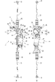
- FIG. 1A is a front view of the electric power steering apparatus 1 viewed from the front side of the vehicle.
- FIG. 1B is a bottom view of the electric power steering apparatus 1 viewed from the lower side of the vehicle.
- the electric power steering apparatus 1 includes a steering mechanism 2 that transmits a steering force from the driver, and a steering assist mechanism 3 that assists the driver's steering operation.
- the steering mechanism 2 mechanically connects a steering wheel (not shown) disposed in the cab of the vehicle and two steered wheels (not shown) that are front wheels of the vehicle.
- the steering mechanism 2 has a steering shaft 7 having an input shaft 4 to which the rotational force from the steering wheel is transmitted and an output shaft 6 connected to the input shaft 4 via a torsion bar 5 (see FIG. 2).
- the transmission mechanism 8 includes a rack and pinion mechanism (rack & pinion mechanism) including a pinion 9 (see FIG. 2) provided on the outer periphery of the output shaft 6 and a rack 11 (see FIG. 2) provided on the outer periphery of the rack bar 10. Pinion gear). Both ends of the rack bar 10 are connected to corresponding steered wheels via tie rods 12 and 12 and knuckle arms 13 and 13, respectively.
- the rack bar 10 is accommodated in an elongated cylindrical rack bar housing part 14.
- the steering assist mechanism 3 includes an electric actuator 15 that applies a steering force to the steering mechanism 2 and a speed reducer 16 connected to the electric actuator 15.
- the electric actuator 15 is located below the rack bar housing portion 14 and is configured integrally with an electronic control unit (ECU) 17.
- the electric actuator 15 is accommodated in the actuator housing 18.
- the electronic control unit 17 has a function of storing and executing various control processes, and drives and controls the electric actuator 15 based on a steering torque signal from the torque sensor 19 and the like.
- the reduction gear 16 includes a reduction gear mechanism that reduces the rotation of an electric motor (not shown) attached to the electric actuator 15.
- the reduction gear 16 is accommodated in a reduction gear housing 20 made of metal such as aluminum.
- the reduction gear housing 20 includes a worm wheel housing portion 22 that accommodates a worm wheel 21 (see FIG. 2), and a worm shaft housing portion 24 that is formed integrally with the worm wheel housing portion 22 and accommodates a worm shaft 23. I have.
- the bellows-like boots 25 and 25 which cover the outer periphery of one end side of the tie rods 12 and 12 are respectively installed at both ends in the axial direction of the rack bar housing portion 14.
- the boots 25, 25 are formed of an elastic material such as a synthetic rubber material so as to ensure a predetermined flexibility, and prevent entry of water or dust into the rack bar 10 or the like.
- mount brackets 26 for attaching the rack bar housing part 14 to the vehicle body are provided at both ends of the rack bar housing part 14 in the axial direction.
- the mount bracket 26 is provided with a rubber bush (not shown), and the rack bar housing portion 14 is attached to the vehicle body via the rubber bush.
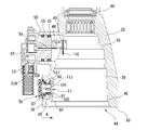
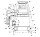
- FIG. 2 is a cross-sectional view of the housing member 27 and the like taken along the steering axis direction.
- the housing member 27 that houses a part of the steering shaft 7 includes a cylindrical sensor housing portion 28, a cylindrical rack and pinion gear housing portion 29, and a cylindrical worm wheel. And a housing portion 22.
- the sensor housing portion 28 is connected to the rack and pinion gear housing portion 29 by bolts 30 (see FIG. 1A).
- the sensor housing portion 28 is provided on one side (upper side in FIG. 2) in the direction of the rotation axis 31 of the steering shaft 7, while the rack and pinion gear housing portion 29 is provided on the rotation axis 31 of the steering shaft 7. It is provided on the other side in the direction of.
- the sensor housing portion 28 and the rack and pinion / gear housing portion 29 communicate with each other inside, and the connection portion between the sensor housing portion 28 and the rack and pinion / gear housing portion 29 is hermetically sealed by a seal member 32 that is continuous in an annular shape.
- the rack and pinion gear housing portion 29 communicates with the boots 25 and 25 via the rack bar housing portion 14, respectively.
- the worm wheel housing portion 22 is connected to the rack and pinion gear housing portion 29 by bolts 33 (see FIG. 1A).
- the worm wheel housing portion 22 and the rack and pinion / gear housing portion 29 communicate with each other inside, and the connection portion between the two is hermetically sealed by a seal member 34 that is annularly continuous.
- the worm wheel housing portion 22 communicates with the actuator housing 18 via the worm shaft housing portion 24.
- the steering shaft 7 extends into the worm wheel housing portion 22 through the sensor housing portion 28 and the rack and pinion / gear housing portion 29.
- the input shaft 4 and the output shaft 6 are connected in the sensor housing portion 28, and the output shaft 6 extends through the rack and pinion gear housing portion 29 to the worm wheel housing portion 22.
- the steering shaft 7 is supported by a bearing 35 such as a ball bearing in the sensor housing portion 28 and the rack and pinion gear housing portion 29.
- the bearing 35 includes an inner race 36, an outer race 37, and a plurality of balls 38 disposed between the inner race 36 and the outer race 37.
- the inner race 36 is fixed to the outer peripheral portion of the output shaft 6.
- the outer race 37 is fitted into an annular groove 42, and the annular groove 42 is formed continuously over the inner peripheral surfaces of both ends of the sensor housing 28 and the opposite ends of the rack and pinion / gear housing 29.
- a pair of stepped portions 40 and 41 is formed.
- the outer peripheral surface of the outer race 37 is in contact with the outer race contact surface portion 43 that is the groove bottom surface of the annular groove 42.
- the outer race contact surface portion 43 overlaps a protrusion contact surface portion 92 described later in the radial direction with respect to the rotation axis 31 of the steering shaft 7.
- the steering shaft 7 is also supported by a bearing 69 (described later) housed in the lower end portion of the rack and pinion gear housing portion 29.
- the sensor housing portion 28 and the rack and pinion / gear housing portion 29 correspond to the “first housing portion” and the “second housing portion” described in the claims, respectively.
- the sensor housing part 28 is formed by metal molding such as aluminum.
- the sensor housing portion 28 is formed in a stepped diameter shape in which the inner diameter of the center portion of the sensor housing portion 28 along the rotation axis 31 is smaller than the inner diameter of the lower portion, that is, the sensor housing portion side opening 44 side.
- the sensor housing part side opening 44 is a joint side opening of the sensor housing part 28 with the rack and pinion / gear housing part 29.
- An annular torque sensor 19 that detects a steering torque that changes in accordance with the amount of twist of the torsion bar 5 is provided around the torsion bar 5 at the center of the sensor housing portion 28.
- the torque sensor 19 is in contact with a step 45 formed on the inner peripheral surface 39 of the sensor housing portion 28 with the torsion bar 5 passing through the annular torque sensor 19.
- the torque sensor 19 is provided closer to the input shaft 4 than the bearing 35.
- the outer diameter of the torque sensor 19 is smaller than the inner diameter of the lower part of the sensor housing portion 28.
- the torque sensor 19 includes a permanent magnet 111, a holder member 112, a pair of first and second yokes 120 and 114, a pair of first and second magnetism collecting rings 115 and 116, a magnetic sensor 117, Consists mainly of.
- the permanent magnet 111, the holder member 112, the yokes 120 and 114, and the magnetism collecting rings 115 and 116 are all arranged so as to be substantially concentric with the rotation axis 31 of the steering shaft 7.
- the permanent magnet 111 is a magnetic member that is formed in a substantially cylindrical shape from a magnetic material and is fixedly attached to the outer periphery of one end of the output shaft 6.
- the permanent magnet 111 is configured by alternately arranging (magnetizing) N and S poles along the circumferential direction of the permanent magnet 111.
- the holder member 112 is formed in a substantially cylindrical shape and is fixedly attached to the outer periphery of one end of the input shaft 4.
- Each of the pair of yokes 120 and 114 is formed in a substantially cylindrical shape by a soft magnetic material, and is connected to the input shaft 4 via the holder member 112, and one end side which is the output shaft 6 side is the permanent magnet 111. It is provided so as to face in the radial direction.
- the yokes 120 and 114 are welded and fixed to the holder member 112 by an annular welding plate (not shown).
- the pair of magnetism collecting rings 115 and 116 is a substantially annular ring that concentrates the magnetic flux generated by the permanent magnet 111 leaking to the other end side of both yokes 120 and 114 within a predetermined range.
- the magnetic flux collecting ring 115 is disposed on the outer peripheral side of the torque sensor 19, while the magnetic flux collecting ring 116 is disposed on the inner peripheral side of the torque sensor 19 so as to face the magnetic collecting ring 115.
- a magnetic flux collecting portion 115a that is pressed radially inward is provided, and on the other hand, at a position facing the magnetic flux collecting portion 115a in the circumferential direction of the magnetic flux collecting ring 116. Is provided with a magnetism collecting portion 116a protruding outward in the radial direction.
- the magnetic sensor 117 is connected to a hall element 118 accommodated in a radial gap between the magnetism collecting part 115a and the magnetism collecting part 116a, and the hall element 118 is connected to a control board 48 arranged above the torque sensor 19. And a connection terminal 49.
- the magnetic sensor 117 detects the magnetic flux passing between the magnetic flux collectors 115 a and 116 a by the Hall element 118 by using the Hall effect by the Hall element, and outputs a signal corresponding to the magnetic flux to the control board 48. Thereby, the calculation of the relative rotation angle between the input shaft 4 and the output shaft 6 in the control board 48 and the calculation of the steering torque based on the relative rotation angle are performed.
- the torque sensor 19 corresponds to a “torque detection member” recited in the claims.
- a harness attachment hole 51 having a circular cross section is formed at the center of the sensor housing portion 28 by a protruding portion 50 that protrudes in an annular shape so as to be orthogonal to the sensor housing portion 28.
- the harness attachment hole 51 is oriented in the same circumferential position as the breathing valve attachment hole 57 in the same direction as the later-described breathing valve attachment hole 57 in the radial direction orthogonal to the rotation axis 31 of the steering shaft 7. That is, the harness attachment hole 51 and the breathing valve attachment hole 57 extend in the radial direction of the sensor housing portion 28 orthogonal to the rotation axis 31 of the steering shaft 7 at the same circumferential position as the breathing valve attachment hole 57.
- a resin connector 53 to which a harness 52 is connected is attached to the harness attachment hole 51. That is, the connector 53 is attached to the harness attachment hole 51 by inserting the cylindrical portion 53 ⁇ / b> A of the connector 53 into the harness attachment hole 51 having a circular cross section.
- a connector terminal 54 is insert-molded in the connector 53, and the connector terminal 54 is connected to the control board 48.
- the contact surface between the projecting portion 50 and the connector 53 is hermetically sealed by two seal members 55 and 55 that are continuous in an annular shape.
- the harness 52 outputs a steering torque signal (output signal) from the torque sensor 19 to the electronic control unit 17 (see FIG. 1) outside the sensor housing portion 28.
- a breathing valve 56 is provided at the lower part of the sensor housing portion 28 to prevent moisture from entering from the outside of the sensor housing portion 28 and allow air to pass bidirectionally between the inside and the outside of the sensor housing portion 28. It has been.
- the breathing valve 56 is disposed on the input shaft 4 side with respect to the bearing 35, and is provided between the torque sensor 19 and the sensor housing portion side opening 44 in the direction of the rotation axis 31 of the steering shaft 7.
- the breathing valve 56 is fitted in a breathing valve mounting hole 57 formed in the sensor housing portion 28.
- the breathing valve 56 adjusts the amount of air in the sensor housing portion 28 provided with the breathing valve 56.
- the breathing valve 56 includes a rack and pinion gear housing portion 29 communicating with the sensor housing portion 28, a worm wheel housing portion 22, a worm shaft housing portion 24, an actuator housing 18, a rack bar housing portion 14 and boots 25 and 25. Adjust the air volume inside.
- the sensor housing portion 28 is formed in a step diameter shape in which the inner diameter of the center portion of the sensor housing portion 28 along the rotation axis 31 is smaller than that of the lower portion. Therefore, the shortest distance between the rotation axis 31 that is the inner diameter of the sensor housing portion 28 and the inner peripheral surface 39 of the sensor housing portion 28 is larger in the region 59 where the breathing valve 56 is provided than in the region 58 where the torque sensor 19 is provided. It has become.
- the region 58 where the torque sensor 19 is provided corresponds to the central portion of the sensor housing portion 28, while the region 59 where the breathing valve 56 is provided corresponds to the lower portion of the sensor housing portion 28.
- the shortest distance D b between the breathing valve 56 and the rotation axis 31 that is the radial distance at the inner end portion 56 a of the breathing valve 56 is based on the maximum value D t of the radial dimension of the torque sensor 19 in the radial dimension with respect to the rotation axis 31. Is also getting smaller. That is, in the region 59 where the breathing valve 56 is provided, the breathing valve 56 projects from the inner peripheral surface 39 of the sensor housing portion 28 into the sensor housing portion 28, and in the radial direction perpendicular to the rotation axis 31, the torque sensor 19. And overlap.
- the shortest distance D b is the inner peripheral surface 39 of the rotation axis 31 direction and the rotation axis 31 is the inner diameter of the sensor housing portion 28 in the region 59 where the breather valve 56 is provided a sensor housing portion 28 of the sensor housing portion 28 It is smaller than the shortest distance D s. That is, in the region 58 where the sensor housing portion 28 is provided, the breathing valve 56 protrudes into the sensor housing portion 28 through the sensor housing portion 28, and the inner end portion 56 a of the breathing valve 56 is in the sensor housing portion 28. It is in a position closer to the rotation axis 31 than the inner peripheral surface 39 of the.
- annular dust seal 60 for dust prevention is provided on the upper portion of the sensor housing portion 28 between the inner peripheral surface 39 of the sensor housing portion 28 and the steering shaft 7.
- the rack and pinion gear housing portion 29 is molded integrally with the elongated cylindrical rack bar housing portion 14 from a metal such as aluminum.
- the rack and pinion gear housing portion 29 includes a rack retainer accommodating portion 61 that protrudes in a cylindrical shape from the rack and pinion gear housing portion 29 so as to be orthogonal to the rotation axis 31.
- a rack retainer 63 having a curved surface 62 that follows the arc surface of the outer periphery of the rack bar 10
- a spring 64 that urges the rack bar 10 toward the output shaft 6, and a rack retainer accommodated
- a closing member 65 that is screwed so as to close the outer end portion of the portion 61 and adjusts the biasing force of the spring 64 is provided.
- the rack retainer accommodating portion 61 and the rack retainer 63 are hermetically sealed by a seal member 119 that is annularly continuous.
- the worm wheel housing part 22 is made of metal, for example, aluminum.
- a worm wheel 21 attached to the tip of the output shaft 6 is accommodated in the worm wheel housing portion 22.
- the worm wheel 21 is formed by insert-molding a metal cored bar 67 having a cylindrical shape on a resin gear forming part 66.
- the cored bar 67 is press-fitted into the output shaft 6.
- the worm wheel 21 is offset from the opening end surface 68 of the worm wheel housing portion 22 toward the rack and pinion gear housing portion 29 side.
- the output shaft 6 is rotatably supported by the rack and pinion gear housing portion 29 via a bearing 69.
- the bearing 69 is, for example, a ball bearing, and includes an inner race 70, an outer race 71, and a plurality of balls 72 disposed between the inner race 70 and the outer race 71.
- the inner race 70 is abutted against a stepped portion 73 formed on the outer periphery of the output shaft 6 and is fixed to the output shaft 6 by a retaining ring 74.
- the outer race 71 is disposed between the stepped portion 75 formed in the rack and pinion gear housing portion 29 and the plate-like fixing member 76.
- the outer race 71 is fixed to the rack and pinion gear housing 29 by fastening the rack and pinion gear housing 29 and the fixing member 76 with bolts 77.
- the worm wheel housing portion side opening 78 located on the opposite side of the rack and pinion gear housing portion 29 is closed by a circular and shallow plate-like closing member 79.
- the closing member 79 is fixed to the opening end surface 68 of the worm wheel housing portion 22 by a plurality of screws 80 (see FIG. 1).
- the worm wheel housing portion 22 and the closing member 79 are hermetically sealed by a sealing member 81 that is continuous in an annular shape.
- a worm shaft 23 that rotates integrally with the output shaft of the electric actuator 15, a worm 82 that is integrally formed on the outer periphery of the worm shaft 23 and meshes with the gear forming portion 66 of the worm wheel 21, Is housed.
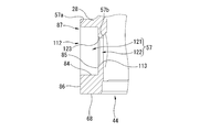
- (Explanation of breathing valve mounting hole) 3 is an enlarged cross-sectional view of a breathing valve mounting hole 57 to which the breathing valve 56 of FIG. 2 is mounted.
- the breathing valve mounting hole 57 is a through hole formed in a step shape by machining so that the inner peripheral side and the outer peripheral side of the sensor housing portion 28 communicate with each other.
- the breathing valve mounting hole 57 communicates with the outer peripheral side hole 121 having a circular cross section extending from the outer peripheral end 57a of the sensor housing part 28 toward the inside of the sensor housing part 28, and the outer peripheral side.
- an inner peripheral side hole 122 formed in a circular cross section smaller than the hole 121.
- the inner peripheral surface 84 of the outer peripheral side hole 121 is machined except for a cast surface 90 described later.
- the inner peripheral surface 113 of the inner peripheral hole 122 and the connection surface 85 between the inner peripheral surface 113 and the inner peripheral surface 84 are machined.
- An arc surface 123 is formed between the inner peripheral surface 84 and the inner peripheral surface 113.
- the inner peripheral surface 84 and the inner peripheral surface 113 of the breathing valve mounting hole 57 correspond to the “inner peripheral surface of the breathing valve mounting hole” recited in the claims.
- the sensor housing portion 28 includes a flat portion 86 formed by machining on the outer peripheral portion thereof.
- the flat surface portion 86 is continuously formed in an annular shape so as to surround the entire circumference of the opening 112 of the end portion 57a on the outer peripheral side of the sensor housing portion 28 among the pair of end portions 57a and 57b of the breathing valve mounting hole 57.
- the annular flat surface portion 86 serves as a surface for bringing a suction port of a vacuum device (not shown) into close contact when performing an airtight test on the housing member 27 and the electric power steering device 1 as a whole through the breathing valve mounting hole 57.
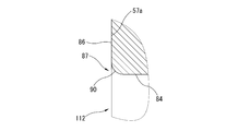
- FIG. 4 is an enlarged cross-sectional view showing the inner peripheral surface 84 of the outer peripheral side hole 121 of the breathing valve mounting hole 57 and a region adjacent thereto.
- a region 87 adjacent to the opening 112 of the breathing valve mounting hole 57 at the end 57a on the outer peripheral side of the sensor housing portion 28 is a sensor housing.
- An uneven curved casting surface 90 formed during casting of the portion 28 is provided.
- the casting surface 90 is smoothly connected to the inner peripheral surface 84 formed by machining.
- the casting surface 90 is continuously formed in an annular shape at the hole edge of the breathing valve mounting hole 57.
- a portion of the inner peripheral surface 113 of the breathing valve mounting hole 57 adjacent to the connection surface 85 is in the middle of the breathing valve mounting hole 57 when the breathing valve 56 is temporarily assembled to the breathing valve mounting hole 57. It becomes the respiratory valve holding
- FIG. 5 is a cross-sectional view of the sensor housing portion 28 taken along line AA in FIG.
- a protrusion contact surface 92 on which a protrusion 98 described later (see FIG. 6) of the breathing valve 56 contacts is adjacent to the inner peripheral surface 113 and the opening end surface 68 of the sensor housing 28. Between the part 44, it forms in the internal peripheral surface 39 by machining.
- the portion of the inner peripheral surface 39 of the sensor housing portion 28 other than the projection contact surface portion 92 is a casting surface 93 formed during casting.
- (Explanation of respiratory valve) 6 is an enlarged cross-sectional view of the breathing valve 56 of FIG.
- the breathing valve 56 includes a cylindrical elastic engagement portion 94 made of an elastic material. As shown in FIG. 6, the elastic engagement portion 94 is formed with a plurality of elongated notches 96 along the central axis 95 of the elastic engagement portion 94. The elastic engagement portion 94 is formed between two cutouts 96, 96 of the plurality of cutouts 96, and an elastic deformation portion 97 extending along the central axis 95, and in the vicinity of the distal end portion 99 of the elastic deformation portion 97. Projecting portion 98. The elastic deformation portion 97 is formed to be elastically deformable radially inward of the breathing valve mounting hole 57 in a cross section orthogonal to the insertion direction A of the breathing valve 56 into the breathing valve mounting hole 57.
- the protrusion 98 protrudes outward in the radial direction of the elastic engagement portion 94 in the vicinity of the distal end portion 99 of the elastic deformation portion 97.
- the protruding portion 98 is provided in a form slightly offset toward the elastic deformation portion 97, and the breathing valve mounting hole 57 is temporarily attached to the distal end portion 99 when the breathing valve 56 is temporarily attached to the breathing valve mounting hole 57.
- the outer surface 100 which contacts the breathing valve holding part 91 on the inner peripheral surface 113 is provided.
- the projecting portion 98 includes a contact surface 101 orthogonal to the elastic deformation portion 97, and the contact surface 101 is such that the outer peripheral surface 94 a of the elastic engagement portion 94 contacts the inner peripheral surface 113 of the breathing valve mounting hole 57.
- the elastic deformation part 97 and the protrusion part 98 constitute what is called a snap fit.
- a flange portion 102 is formed on the end portion of the elastic engagement portion 94 on the side opposite to the protruding portion 98 so as to project annularly outwardly in the radial direction of the elastic engagement portion 94.
- the breathing valve 56 further includes a filter 104 that closes the opening 103 on the flange portion 102 side of the cylindrical elastic engagement portion 94.
- the filter 104 is a water-repellent filter configured to pass gas but not liquid.
- a porous film such as polytetrafluoroethylene (PTFE) can be used.
- the breathing valve 56 is provided with a filter protection unit 105 that protects the filter 104 against external force.
- the filter protection part 105 has a plate shape and protects the filter 104 by covering the filter 104 from the opposite side of the elastic deformation part 97.
- the filter protection part 105 is connected to the flange part 102 via a connection part 106 formed on the outer periphery of the flange part 102.
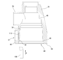
- FIG. 7 shows a protrusion contact surface portion forming step for forming the protrusion contact surface portion 92 with which the protrusion 98 of the breathing valve 56 contacts.
- the cutting tool 108 is inserted into the sensor housing portion 28 from the sensor housing portion side opening 44, and the sensor housing is disposed around the breathing valve mounting hole 57.
- the inner peripheral surface 39 of the portion 28 is partially machined.
- a part of the inner peripheral surface 39 of the sensor housing portion 28 is machined between the inner peripheral surface 113 of the breathing valve mounting hole 57 and the sensor housing portion side opening 44.
- the shallow groove-shaped protrusion contact surface portion 92 is formed (see FIG. 5).
- the protrusion contact surface portion forming step is a step of forming the protrusion contact surface portion 92 by the sensor housing portion forming mold simultaneously with the molding of the sensor housing portion 28 by the sensor housing portion forming mold (not shown). It may be.
- FIG. 8 shows a breathing valve temporary assembling step for temporarily assembling the breathing valve 56 in the breathing valve mounting hole 57 of the sensor housing portion 28.
- the breathing valve 56 is temporarily assembled to the breathing valve mounting hole 57 by inserting the breathing valve 56 in the insertion direction A halfway through the breathing valve mounting hole 57.
- the tip of the elastic engagement portion 94 is inserted into the breathing valve mounting hole 57, so that the tip of the elastic engagement portion 94 is attached to the breathing valve holding portion 91 of the breathing valve mounting hole 57. It comes into contact.
- the elastic deformation portion 97 is appropriately elastically deformed inward of the breathing valve mounting hole 57, and the outer surface 100 of the distal end portion 99 of the elastic deformation portion 97 is elastically applied to the breathing valve holding portion 91 by the reaction force.
- the breathing valve 56 By contacting, the breathing valve 56 is temporarily assembled in the breathing valve mounting hole 57 in the middle of the breathing valve mounting hole 57. At this time, the filter 104 and the filter protection part 105 of the breathing valve 56 protrude outward from the flat part 86 on the outer periphery of the sensor housing part 28.
- FIG. 9 shows a torque sensor insertion step of inserting the torque sensor 19 from the sensor housing portion side opening 44.
- the hall element 118 is mounted on the control board 48, the connector terminal 54 is connected to the control board 48, and the control board 48 including the hall element 118 and the connector terminal 54 is inserted into the harness attachment hole 51.
- the torque sensor 19 is inserted into the sensor housing portion 28 from the sensor housing portion side opening 44.
- the torque sensor 19 is inserted in the direction indicated by the arrow C in FIG. 9 until the annular end surface 109 of the torque sensor 19 contacts the stepped portion 45 of the sensor housing portion 28.
- the torque sensor 19 is assembled to the sensor housing portion 28 so that the Hall element 118 mounted on the control board 48 is accommodated between the magnetism collecting rings 115 and 116.
- FIG. 10 shows a breathing valve assembling step for assembling the breathing valve 56 temporarily assembled in the breathing valve temporary assembling step into the breathing valve mounting hole 57 of the sensor housing portion 28.
- the temporarily assembled breathing valve 56 is further pushed into the breathing valve mounting hole 57 along the insertion direction A, thereby breathing into the breathing valve mounting hole 57 at the mounting position 110 of the sensor housing portion 28.
- the valve 56 is assembled.
- the assembly position 110 of the sensor housing portion 28 is a final assembly position when the breathing valve 56 is completely inserted into the breathing valve mounting hole 57.
- the projection 98 of the breathing valve 56 abuts against the projection abutting surface 92 of the sensor housing 28 by a so-called snap fit, so that the breathing valve 56 is in contact with the sensor housing 28. Is retained.
- the seal member 107 is in contact with the elastic engagement portion 94, the flange portion 102, and the connection surface 85.
- the breathing valve 56 protrudes to the inner peripheral side of the sensor housing portion 28 from the outer peripheral portion of the torque sensor 19.
- the filter 104 and the filter protection part 105 of the breathing valve 56 are accommodated in the outer peripheral side hole 121 of the sensor housing part 28.
- FIG. 11 shows a housing connection process for connecting the sensor housing portion 28 and the rack and pinion / gear housing portion 29.
- the sensor housing portion 28 and the rack and pinion / gear housing portion 29 are connected by a bolt 30 (see FIG. 1A).
- the housing portions 28 and 29 are connected after the bearing 35 is disposed so that the outer race 37 of the bearing 35 contacts the step portion 40 of the sensor housing portion 28 and the step portion 41 of the rack and pinion / gear housing portion 29. .
- the breathing valve 56 is assembled to the sensor housing portion 28 connected to the rack and pinion gear housing portion 29. Accordingly, the amount of air in the sensor housing portion 28 and the rack and pinion gear housing portion 29 and the amount of air in the actuator housing 18 and the like communicating with the rack and pinion gear housing portion 29 can be adjusted.
- relatively high-temperature heat generated by the electric motor may cause the air in the actuator housing 18 to expand. It is necessary to adjust the air volume.
- the sensor housing portion 28 having the breathing valve 56 communicates with the actuator housing 18 via the rack and pinion gear housing portion 29 and the worm shaft housing portion 24. Accordingly, the amount of air in the actuator housing 18 can be adjusted, and the air expanded by the heat from the electric motor can be released to the outside of the sensor housing portion 28.
- the bellows-like boots 25, 25 may expand or contract due to the amount of air inside, causing damage such as cracks in the boot 25. It is necessary to adjust the air volume.
- the sensor housing portion 28 including the breathing valve 56 communicates with the boots 25 and 25 via the rack and pinion gear housing portion 29 and the rack bar housing portion 14. Therefore, the amount of air in the boots 25 and 25 can be adjusted by the breathing valve 56 to suppress excessive expansion and contraction of the boot 25 and reduce damage to the boot 25.
- the breathing valve 56 protrudes inward from the inner peripheral surface 39 of the sensor housing portion 28 between the torque sensor 19 of the sensor housing portion 28 and the sensor housing portion side opening 44.
- the space of the sensor housing portion 28 between the torque sensor 19 and the sensor housing portion side opening 44 is wider than the region 58 where the torque sensor 19 is provided, and the torque sensor After 19 is inserted, it becomes a dead space. Therefore, space efficiency can be improved by extending the breathing valve 56 into the dead space in the region 59.
- the breathing valve 56 is assembled at the assembly position 110 of the sensor housing portion 28 in the breathing valve assembly process after the torque sensor insertion process. If the torque sensor 19 is inserted into the sensor housing portion 28 after the breathing valve 56 is assembled in the breathing valve mounting hole 57, the torque sensor 19 interferes with the breathing valve 56. However, it is possible to prevent the breathing valve 56 from interfering with the torque sensor 19 by assembling the breathing valve 56 at the assembling position 110 after the torque sensor 19 has passed the breathing valve attachment position as in the present embodiment. it can. This effect is also realized in a mode in which the breathing valve 56 is temporarily assembled to the sensor housing portion 28 and the breathing valve 56 is not assembled in the final assembly position before the torque sensor insertion step.
- the shortest distance D b between the inner end portion 56a and the rotation axis 31 of the steering shaft 7 breathing valve 56 is smaller than the maximum value D t of the radial dimension of the torque sensor 19. Therefore, interference between the torque sensor 19 and the breathing valve 56 can be suppressed while increasing space efficiency.
- the shortest distance D b is smaller than the shortest distance D s between the inner peripheral surface 39 of the sensor housing portion 28 and the rotation axis 31 at the lower portion of the sensor housing portion 28. Accordingly, the inner end portion 56a of the breathing valve 56 protrudes to the inner peripheral side from the inner peripheral surface 39 of the sensor housing portion 28, and the dead space below the sensor housing portion 28 can be used more effectively. Can be improved.
- the torque sensor 19 and the respiratory valve 56 are suppressed.
- the breathing valve 56 is assembled to the breathing valve mounting hole 57 of the sensor housing portion 28 by a so-called snap fit by the elastic deformation portion 97 and the projection portion 98 of the breathing valve 56. Therefore, the workability of assembling the breathing valve 56 to the sensor housing portion 28 is good.
- both the breathing valve mounting hole 57 and the harness mounting hole 51 extend in the radial direction of the sensor housing portion 28. Therefore, when the breathing valve mounting hole 57 and the harness mounting hole 51 are formed by molding, both are in the same mold release direction, so that the mold division can be simplified and the complexity of the mold division can be suppressed.
- the casting surface 90 is formed instead of the edge between the flat portion 86 and the inner peripheral surface 84, when the respiratory valve 56 is inserted into the respiratory valve mounting hole 57.
- the seal member 107 comes into contact with the curved casting surface 90. Therefore, damage to the seal member 107 when the breathing valve 56 is inserted can be suppressed.
- a smooth arc surface 123 is formed between the connection surface 85 and the inner peripheral surface 113.
- a breathing valve holding portion 91 is provided on the inner peripheral surface 113 of the breathing valve mounting hole 57. Therefore, it is possible to adopt a procedure in which the torque sensor 19 is assembled in a state where the breathing valve 56 is temporarily assembled in the breathing valve holding portion 91 and then the breathing valve 56 is assembled in the final assembly position. it can.
- the housing member 27 and the entire electric power steering apparatus 1 are hermetically sealed via the breathing valve mounting hole 57.
- the suction port of the vacuum device can be brought into close contact with the flat portion 86.
- the projecting portion contact surface portion 92 is continuously formed between the inner peripheral surface 39 and the sensor housing portion side opening 44. This makes it possible to form the protruding portion contact surface portion 92 from the sensor housing portion side opening 44 side, compared to the case where the protruding portion contact surface portion 92 is formed via the breathing valve mounting hole 57.
- the contact surface portion 92 can be easily formed.
- the cutting tool 108 is inserted into the sensor housing portion 28 from the relatively wide sensor housing portion side opening 44, and the protrusion contact surface portion 92 is formed by machining. Forming. Therefore, the machining tool can be easily inserted from the sensor housing portion side opening 44 side, and the projection contact surface portion 92 can be easily machined. Moreover, since the projection contact surface portion 92 is formed by machining, the dimensional accuracy and shape accuracy are good.
- the inner peripheral surface 39 of the sensor housing portion 28 in the region 59 where the breathing valve 56 is provided is a cast surface 93 other than the projection contact surface portion 92, the processing man-hour of the sensor housing portion 28 is increased. Can be reduced.
- the inner diameter of the sensor housing portion 28 including the portion of the casting surface 93 is larger than the inner diameter of the region 58 where the torque sensor 19 is assembled, the torque sensor 19 and the casting surface 93 interfere when the torque sensor 19 is inserted. And it can suppress that the torque sensor 19 is damaged.
- the projecting portion abutting surface portion forming step is performed simultaneously with the molding of the sensor housing portion 28 by the sensor housing portion forming mold (not shown) and the projecting portion contacting surface by the sensor housing portion forming mold.
- This is a process for forming the surface portion 92. Therefore, the protrusion contact surface 92 can be formed by die cutting, and the formation work of the protrusion contact surface 92 can be simplified.
- the arc-shaped outer race contact surface portion 43 overlaps the protrusion contact surface portion 92 in the radial direction with respect to the rotation axis 31.
- the outer race contact surface portion 43 and the protrusion contact surface portion 92 are overlapped within a range that does not hinder the holding of the bearing 35, whereby the radial dimension of the sensor housing portion 28 can be reduced. .
- a steering shaft 7 having an input shaft 4 to which a rotational force from the steering wheel is transmitted, and an output shaft 6 connected to the input shaft 4 via a torsion bar 5, and rotating the steering shaft 7.
- a steering mechanism 2 having a transmission mechanism 8 for transmitting to a steered wheel, and a housing member 27 for housing at least a part of the steering shaft 7, a sensor provided on one side in the direction of the rotation axis 31 of the steering shaft 7
- a housing member 27 including a housing portion 28 and a rack and pinion gear housing portion 29 provided on the other side and connected to the sensor housing portion 28, and a bearing provided on the housing member 27 and supporting the output shaft 6.
- the power steering apparatus 1 includes a breathing valve 56 that is capable of passing air in both directions between the inside and the outside of the housing member 27 and that is disposed on the input shaft 4 side with respect to the bearing 35.
- the manufacturing method includes a torque sensor insertion step of inserting the torque sensor 19 from the sensor housing portion side opening 44 which is a joint portion side opening of the sensor housing portion 28 to the rack and pinion / gear housing portion 29, and a breathing valve 56 After the breathing valve assembly process to be assembled to the sensor housing portion 28 and the torque sensor insertion process, the sensor housing Having a housing connecting step for connecting the grayed portion 28 and the rack-and-pinion gear housing portion 29, a.
- the air amount in the sensor housing portion 28 and the air amount in the rack and pinion gear housing portion 29 communicating with the sensor housing portion 28 can be adjusted.
- the breathing valve 56 is provided between the torque sensor 19 and the sensor housing portion side opening 44 in the direction of the rotation axis 31 in the sensor housing portion 28.
- the area between the torque sensor housing portion of the sensor housing portion 28 and the sensor housing portion side opening 44 has an inner diameter dimension equal to or larger than the inner diameter dimension of the torque sensor housing portion. Since the internal space has a relatively large margin, the space efficiency can be improved by providing the breathing valve 56 in this region.
- the breathing valve 56 is assembled at the assembly position of the sensor housing portion 28 after the torque sensor insertion process is completed.
- the breathing valve 56 can be prevented from interfering with the torque sensor 19 by assembling the breathing valve 56 at the assembling position.
- the shortest distance between the respiration valve 56 and the rotation axis 31 after the respiration valve assembly step is smaller than the maximum value of the radial dimension of the torque sensor 19 in the radial dimension with respect to the rotation axis 31.
- the minimum distance D b between the breather valve 56 is a radial distance of the inner end portion 56a of the breather valve 56 after the assembly process breathing valve and the axis of rotation 31, in the direction of the rotation axis of the sensor housing portion 28 It is smaller than the shortest distance D s between the rotation axis 31 that is the inner diameter of the sensor housing portion 28 and the inner peripheral surface 39 of the sensor housing portion 28 in the region where the breathing valve 56 is provided.
- the breathing valve 56 so that the tip of the breathing valve 56 protrudes from the inner peripheral surface 39 of the sensor housing portion 28, space efficiency can be improved. Further, since it is after the torque sensor insertion process that the breathing valve 56 is assembled to the position where the breathing valve 56 protrudes from the inner peripheral surface 39 of the sensor housing portion 28, the interference between the torque sensor 19 and the breathing valve 56 is suppressed. be able to.
- the sensor housing portion 28 is a through hole that communicates the inside and the outside of the sensor housing portion 28, and includes a breathing valve mounting hole 57 in which the breathing valve 56 is provided.
- the breathing valve 56 is formed of an elastic material.
- the elastic engagement portion 94 includes an elastic deformation portion 97 and a protrusion 98 provided on the elastic deformation portion 97.
- the elastic deformation portion 97 is connected to the breathing valve mounting hole 57.
- the projection 98 can be elastically deformed in the inner direction of the breathing valve mounting hole 57, and the protruding portion 98 is in contact with the inner peripheral surface 113 of the breathing valve mounting hole 57.
- the breathing valve 56 In contact with the inner surface 39 of the sensor housing 28, the breathing valve 56 is configured to be restricted from moving out of the breathing valve mounting hole 57.
- the breathing valve 56 is fixed to the sensor housing portion 28 by so-called snap fit, the assembly workability is good.
- the sensor housing portion 28 is a through hole that is formed by molding and communicates the inside and the outside of the sensor housing portion 28, and includes a breathing valve mounting hole 57 in which the breathing valve 56 is provided, and a torque sensor. 19 is provided with a harness attachment hole 51 provided with a harness 52 for outputting an output signal from the sensor housing portion 28 to the outside, and the breathing valve attachment hole 57 and the harness attachment hole 51 are in the same direction in the radial direction with respect to the rotation axis 31. Suitable for.
- the sensor housing portion 28 is formed by molding, and includes a breathing valve mounting hole 57 that is a through hole that communicates the inside and the outside of the sensor housing portion 28 and is provided with a breathing valve 56.
- the valve mounting hole 57 is formed by machining the inner peripheral surfaces 84 and 113 of the breathing valve mounting hole 57, and the outer end of the sensor housing portion 28 among the pair of end portions 57 a and 57 b of the breathing valve mounting hole 57.
- a region 87 adjacent to the opening 112 of the breathing valve mounting hole 57 in 57 b has a cast surface 90 in the molding of the sensor housing portion 28 and is continuous with the inner peripheral surface 84 by machining of the breathing valve mounting hole 57. It is formed in the curved surface shape formed.
- the boundary portion has a gentle curved surface. Damage to the seal member 107 when the valve 56 is inserted can be suppressed.
- the sensor housing portion 28 is a through hole that communicates the inside and the outside of the sensor housing portion 28, and includes a breathing valve mounting hole 57 in which the breathing valve 56 is provided. In the insertion direction A of 56, a breathing valve holding portion 91 that can hold the breathing valve 56 in the middle of the breathing valve attachment hole 57 is provided.
- the sensor housing portion 28 is a through hole that communicates the inside and outside of the sensor housing portion 28, and is provided on the outer peripheral side of the sensor housing portion 28 and the breathing valve mounting hole 57 in which the breathing valve 56 is provided.
- the flat surface portion 86 is formed so as to surround the entire circumference of the opening of the outer end portion of the sensor housing portion 28 among the pair of end portions of the breathing valve mounting hole 57.
- a suction port of a vacuum device (not shown) can be brought into close contact with the flat portion 86.
- the method for manufacturing the power steering device 1 includes a protrusion contact surface portion forming step performed before the torque sensor insertion step and the breathing valve assembly step, and the sensor housing portion 28 A through-hole communicating between the inner side and the outer side is provided with a breathing valve mounting hole 57 in which a breathing valve 56 is provided.
- the breathing valve 56 includes an elastic engagement portion 94 formed of an elastic material, and the elastic engagement portion 94 includes an elastic deformation portion 97 and a protrusion 98 provided on the elastic deformation portion 97.
- the elastic deformation portion 97 is a breathing valve in a cross section orthogonal to the insertion direction A of the breathing valve 56 into the breathing valve mounting hole 57.
- the sensor housing portion 28 can be elastically deformed inwardly of the attachment hole 57, and the protruding portion 98 is in a state where the elastic deformation portion 97 contacts the inner peripheral surface 113 of the breathing valve attachment hole 57.
- the sensor housing portion 28 is formed in the projecting portion abutting surface portion forming step so as to restrict the breathing valve 56 from moving in the direction of coming out of the breathing valve mounting hole 57 by abutting the inner peripheral surface.
- the sensor housing portion 28 has a projection contact surface 92 which is provided on the inner peripheral side and is a flat surface with which the projection 98 of the breathing valve 56 contacts, and is formed up to the sensor housing portion opening 44.
- the protrusion contact surface 92 extends to the sensor housing portion opening 44, the protrusion contact surface 92 can be formed from the sensor housing portion opening 44 side, and the sensor housing portion 28 has an outer peripheral side. As compared with the case where the projection contact surface portion 92 is formed through the breathing valve mounting hole 57, the formation is easier.
- the protrusion contact surface portion forming step is a step of forming the protrusion contact surface portion 92 by machining from the sensor housing portion side opening 44 side.
- the machining tool can easily enter from the sensor housing portion side opening 44 side, and the projection contact surface portion 92 can be easily machined. Moreover, since the projection contact surface portion 92 is formed by machining, the dimensional accuracy and shape accuracy are good.
- the sensor housing portion 28 is formed by molding, and the shortest distance between the rotation axis 31 that is the inner diameter of the sensor housing portion 28 and the inner peripheral surface 39 of the sensor housing portion 28 is larger than the region where the torque sensor 19 is provided.
- the area in which the breathing valve 56 is provided is larger, and the inner peripheral surface 39 of the sensor housing part 28 in the area in which the breathing valve 56 is provided in the direction of the rotation axis 31 of the sensor housing part 28 is other than the protrusion contact surface part 92.
- the portion has a cast surface 93 formed by molding.
- the processing man-hours of the sensor housing portion 28 can be suppressed by leaving the region where the breathing valve 56 is provided in the rotation axis direction (excluding the protrusion contact surface portion 92) as the casting surface 93.
- the torque sensor 19 passes through the portion of the casting surface 93 when assembled. Since the inner diameter of this portion is larger than the region where the torque sensor 19 is assembled, It is possible to prevent the torque sensor 19 from being damaged due to contact with the casting surface 93.
- the sensor housing portion 28 is formed by molding, and in the projecting portion abutting surface portion forming step, the projecting portion abutting surface portion 92 is formed by the mold for forming the sensor housing portion 28 simultaneously with the molding of the sensor housing portion 28. It is a process to do.
- the projection contact surface portion 92 extends to the sensor housing portion side opening 44, the projection contact surface portion 92 can be formed by die cutting, which simplifies the work of forming the projection contact surface portion 92. Can be planned.
- the bearing 35 is a ball bearing
- the sensor housing portion 28 is provided on the inner peripheral side of the sensor housing portion 28 and on the sensor housing portion side opening 44 side, and the outer peripheral surface of the outer race 37 of the ball bearing is
- the outer race contact surface portion 43 that is an arc surface to contact is provided, and the outer race contact surface portion 43 is provided so as to overlap with the protrusion portion contact surface portion 92 in the radial direction with respect to the rotation axis 31.
- the outer dimension of the outer race contact surface portion 43 and the protrusion contact surface portion 92 are overlapped within a range that does not hinder the holding of the ball bearing, whereby the radial dimension of the sensor housing portion 28 can be reduced.
- a steering shaft having an input shaft to which a rotational force from a steering wheel is transmitted, and an output shaft connected to the input shaft via a torsion bar
- a steering mechanism having a transmission mechanism for transmitting the rotation of the steering shaft to the steered wheels, and a housing member that accommodates at least a part of the steering shaft, provided on one side in the direction of the rotation axis of the steering shaft
- a first housing part provided on the other side and a second housing part connected to the first housing part
- a bearing provided on the housing member for supporting the output shaft;
- the steering torque that is provided in the first housing portion and closer to the input shaft than the bearing is detected according to the torsion amount of the torsion bar.
- a torque detection member an actuator for applying a steering force to the steering mechanism based on the steering torque, and a breathing valve provided in the first housing portion, which is configured to prevent moisture from entering the housing member. And a breathing valve disposed on the input shaft side of the bearing, wherein the torque detecting member is capable of suppressing air and allowing the air to pass bidirectionally between the inside and the outside of the housing member.
- a torque detecting member inserting step of inserting the first housing part from the first housing part side opening part, which is a joint part side opening of the first housing part with the second housing part, and a breathing valve for assembling the breathing valve to the first housing part An assembling step and a housing connecting step for connecting the first housing portion and the second housing portion after the torque detecting member inserting step; The has.
- the breathing valve is provided between the torque detection member and the first housing portion side opening in the direction of the rotation axis in the first housing portion. Yes.
- the breathing valve assembly step may be configured such that the breathing valve is assembled to the first housing portion after the torque detecting member insertion step is completed. Assemble at the attachment position.
- the shortest distance between the respiratory valve and the rotation axis after the breathing valve assembly step is a radial dimension with respect to the rotation axis. It is smaller than the maximum value of the radial dimension of the torque detection member.
- the respiration valve that is a radial distance at the inner end of the respiration valve after the respiration valve assembly step, and the rotation axis Is the shortest distance between the rotation axis that is the inner diameter of the first housing part and the inner peripheral surface of the first housing part in the region where the breathing valve is provided in the direction of the rotation axis of the first housing part. Smaller than the shortest distance.
- the first housing part is a through-hole that communicates the inside and the outside of the first housing part, and the breathing valve A breathing valve mounting hole, wherein the breathing valve includes an elastic engagement portion formed of an elastic material, and the elastic engagement portion includes an elastic deformation portion and a protrusion provided in the elastic deformation portion.
- the elastically deformable portion is elastically deformable inward of the breathing valve mounting hole in a cross section orthogonal to the direction of insertion of the respiratory valve into the breathing valve mounting hole, and the protrusion is elastic In a state where the deforming portion is in contact with the inner peripheral surface of the breathing valve mounting hole, the breathing valve is pulled out from the breathing valve mounting hole by contacting the inner peripheral surface of the first housing portion. It is formed so as to restrict the movement of the.
- the first housing part is formed by molding, and penetrates the inside and the outside of the first housing part.
- the attachment hole and the harness attachment hole are oriented in the same direction in the radial direction with respect to the rotation axis.
- the first housing part is formed by molding, and penetrates the inside and the outside of the first housing part.
- a breathing valve mounting hole in which the breathing valve is provided the breathing valve mounting hole being formed by machining an inner peripheral surface of the breathing valve mounting hole, and a pair of the breathing valve mounting holes.
- the region adjacent to the opening of the breathing valve mounting hole in the outer end portion of the first housing portion among the end portions has a cast surface in the molding of the first housing portion, and the breathing valve mounting hole Is formed into a curved surface formed continuously with the inner peripheral surface by machining.
- the first housing part is a through-hole that communicates the inside and the outside of the first housing part, and the breathing valve
- the breathing valve mounting hole has a breathing valve holding portion capable of holding the breathing valve in the middle of the breathing valve mounting hole in the insertion direction of the breathing valve.
- the first housing part is a through-hole that communicates the inside and the outside of the first housing part, and the breathing valve And a flat surface portion provided on the outer peripheral side of the first housing portion, the flat surface portion of the pair of end portions of the breathing valve mounting hole. It is formed so as to surround the entire circumference of the opening at the outer end.
- a projecting portion contact surface portion forming step performed before the torque detecting member inserting step and the breathing valve assembly step is provided.
- the first housing part is a through hole that communicates the inside and the outside of the first housing part, and includes a breathing valve mounting hole in which the breathing valve is provided, and the breathing valve is formed of an elastic material.
- the elastic engagement portion includes an elastic deformation portion and a protrusion provided on the elastic deformation portion, and the elastic deformation portion is provided on the breathing valve mounting hole.
- the breathing valve is configured to be restricted from moving in a direction of coming out of the breathing valve mounting hole by contacting the inner peripheral surface of the first housing part, and the first housing part includes the protrusion Formed in the part abutting surface part forming step, provided on the inner peripheral side of the first housing part, and formed as far as the opening part on the first housing part side, which is a flat part on which the projection part of the breathing valve abuts. And a protruding portion contact surface portion.
- the protrusion contact surface portion forming step includes machining the protrusion contact surface portion by machining from the first housing portion side opening side. Is a step of forming.
- the first housing part is formed by molding, and the rotation axis that is an inner diameter of the first housing part and the first
- the shortest distance of the inner peripheral surface of the housing part is larger in the area where the breathing valve is provided than in the area where the torque detection member is provided, and the breathing valve is provided in the direction of the rotation axis of the first housing part.
- the inner peripheral surface of the first housing portion in the region to be formed has a casting surface in which a portion other than the protrusion contact surface portion is formed by the molding.
- the first housing part is formed by molding
- the projecting part contact surface part forming step includes the step of forming the first housing part. It is a step of forming the protrusion contact surface portion by the first housing portion forming die simultaneously with the molding.
- the bearing is a ball bearing
- the first housing part is an inner peripheral side of the first housing part
- An outer race contact surface portion that is provided on the first housing portion side opening portion side and is an arc surface on which an outer peripheral surface of the outer race of the ball bearing contacts, and the outer race contact surface portion is It is provided so as to overlap with the protrusion contact surface portion.
Landscapes
- Engineering & Computer Science (AREA)
- Chemical & Material Sciences (AREA)
- Combustion & Propulsion (AREA)
- Transportation (AREA)
- Mechanical Engineering (AREA)
- Power Steering Mechanism (AREA)
Abstract
電動パワーステアリング装置(1)の製造方法では、突起部当接面部形成工程において、センサハウジング部(28)の内周面(39)を部分的に機械加工することにより、突起部当接面部(92)を形成する。そして、呼吸弁仮組付け工程において、呼吸弁取り付け孔(57)に対して呼吸弁(56)を仮組付けする。次に、トルクセンサ挿入工程において、センサハウジング部側開口部(44)からセンサハウジング部(28)内にトルクセンサ(19)を挿入する。そして、呼吸弁組付け工程において、センサハウジング部(28)の組付け位置(110)において呼吸弁取り付け孔(57)に呼吸弁(56)を組付ける。次に、ハウジング接続工程において、センサハウジング部(28)とラック&ピニオン・ギヤハウジング部(29)とを互いに接続する。
Description
本発明は、パワーステアリング装置の製造方法に関する。
パワーステアリング装置に使用される電子制御ユニットとして、例えば以下の特許文献1に記載された電子制御ユニットが知られている。
特許文献1に記載の電子制御ユニットでは、電子制御ユニットのハウジングに、このハウジング内の空気量を調整する呼吸弁が取り付けられている。
特許文献1では、独立した電子制御ユニットのハウジングに呼吸弁が設けられており、ステアリングギヤやモータ用のハウジング内の空気量を調整することができないという問題があった。
本発明は、従来の実情に鑑みて案出されたもので、ステアリングギヤ等のハウジング内の空気量を調整するためのパワーステアリング装置の製造方法を提供することを目的としている。
本発明によれば、その1つの態様において、操舵軸の少なくとも一部を収容するハウジング部材の第1ハウジング部に呼吸弁を組付けることを特徴としている。
本発明によれば、呼吸弁により、第1ハウジング部およびこれに接続された第2ハウジング部内の空気量が調整される。
以下、本発明の製造方法が適用される電動パワーステアリング装置の一実施例を図面に基づき説明する。
(パワーステアリング装置の構成)
図1(a)は、車両の前方側から見た電動パワーステアリング装置1の正面図である。図1(b)は、車両の下側から見た電動パワーステアリング装置1の底面図である。
(パワーステアリング装置の構成)
図1(a)は、車両の前方側から見た電動パワーステアリング装置1の正面図である。図1(b)は、車両の下側から見た電動パワーステアリング装置1の底面図である。
図1に示すように、電動パワーステアリング装置1は、運転者からの操舵力を伝達する操舵機構2と、運転者の操舵操作を補助する操舵アシスト機構3と、を備えている。
操舵機構2は、車両の運転室内に配置された図示せぬステアリングホイールと、車両の前輪である図示せぬ2つの転舵輪と、を機械的に連結している。操舵機構2は、上記ステアリングホイールからの回転力が伝達される入力軸4と、トーションバー5(図2参照)を介して入力軸4に接続された出力軸6と、を有した操舵軸7、およびこの操舵軸7の回転を図示せぬ転舵輪に伝達する伝達機構8を備えている。伝達機構8は、出力軸6の外周に設けられたピニオン9(図2参照)と、ラックバー10の外周に設けられたラック11(図2参照)と、からなるラック&ピニオン機構(ラック&ピニオン・ギヤ)により構成されている。ラックバー10の両端は、タイロッド12,12およびナックルアーム13,13を介して対応する転舵輪にそれぞれ連結されている。ラックバー10は、細長い円筒状のラックバーハウジング部14内に収容されている。
操舵アシスト機構3は、操舵機構2に操舵力を付与する電動アクチュエータ15と、この電動アクチュエータ15に接続された減速機16と、を備えている。電動アクチュエータ15は、ラックバーハウジング部14の下方に位置しており、電子制御ユニット(ECU)17と一体に構成されている。電動アクチュエータ15は、アクチュエータハウジング18内に収容されている。電子制御ユニット17は、各種制御処理を記憶および実行する機能を有し、トルクセンサ19からの操舵トルクの信号等に基づいて電動アクチュエータ15を駆動制御する。
減速機16は、電動アクチュエータ15に付随する図示せぬ電動モータの回転を減速する減速ギヤ機構を備えている。減速機16は、金属例えばアルミニウムからなる減速機ハウジング20内に収容されている。減速機ハウジング20は、ウォームホイール21(図2参照)を収容するウォームホイールハウジング部22と、このウォームホイールハウジング部22と一体に形成され、ウォーム軸23を収容するウォーム軸ハウジング部24と、を備えている。
ラックバーハウジング部14の軸方向両端には、それぞれタイロッド12,12の一端側外周を覆う蛇腹状のブーツ25,25が設置されている。ブーツ25,25は、弾性材料例えば合成ゴム材料により所定の可撓性を確保するように形成されており、ラックバー10等への水や埃等の侵入を防止している。
さらに、ラックバーハウジング部14の軸方向両端には、このラックバーハウジング部14を車体に取り付けるためのマウントブラケット26がそれぞれ設けられている。マウントブラケット26には、図示せぬゴムブッシュが設置され、このゴムブッシュを介して、ラックバーハウジング部14が車体に取り付けられる。
かかる電動パワーステアリング装置1の構成から、運転者がステアリングホイールを回転操作すると、入力軸4が回転してトーションバー5が捩られ、これにより生じるトーションバー5の弾性力によって、出力軸6が回転する。そして、出力軸6の回転運動が上記ラック&ピニオン機構によりラックバー10の軸方向に沿う直線運動に変換され、タイロッド12,12を介してナックルアーム13,13が車幅方向へと引っ張られることによって、対応した転舵輪の向きが変更される。
図2は、操舵軸方向に沿って取ったハウジング部材27等の断面図である。
図2に示すように、操舵軸7の一部を収容するハウジング部材27が、円筒状のセンサハウジング部28と、同じく円筒状のラック&ピニオン・ギヤハウジング部29と、同じく円筒状のウォームホイールハウジング部22と、を備えている。センサハウジング部28は、ボルト30(図1(a)参照)によってラック&ピニオン・ギヤハウジング部29に接続されている。センサハウジング部28は、操舵軸7の回転軸線31の方向において一方側(図2の上方側)に設けられており、一方、ラック&ピニオン・ギヤハウジング部29は、操舵軸7の回転軸線31の方向において他方側に設けられている。センサハウジング部28とラック&ピニオン・ギヤハウジング部29とは、内部において互いに連通しており、両者の接続部間は、環状に連続したシール部材32によって気密にシールされている。また、ラック&ピニオン・ギヤハウジング部29は、ラックバーハウジング部14を介してブーツ25,25とそれぞれ連通している。
また、ウォームホイールハウジング部22は、ボルト33(図1(a)参照)によってラック&ピニオン・ギヤハウジング部29に接続されている。ウォームホイールハウジング部22とラック&ピニオン・ギヤハウジング部29とは、内部において互いに連通しており、両者の接続部間は環状に連続したシール部材34によって気密にシールされている。ウォームホイールハウジング部22は、ウォーム軸ハウジング部24を介してアクチュエータハウジング18と連通している。
このように構成されたハウジング部材27において、操舵軸7は、センサハウジング部28およびラック&ピニオン・ギヤハウジング部29を通してウォームホイールハウジング部22内に延びている。具体的には、センサハウジング部28において入力軸4と出力軸6が接続され、出力軸6がラック&ピニオン・ギヤハウジング部29を貫通してウォームホイールハウジング部22まで延びている。操舵軸7は、センサハウジング部28およびラック&ピニオン・ギヤハウジング部29において、軸受35例えばボールベアリングによって軸支されている。軸受35は、インナレース36と、アウタレース37と、インナレース36とアウタレース37との間に配置された複数のボール38と、を備えている。インナレース36は、出力軸6の外周部に固定されている。アウタレース37は、環状溝42に嵌め込まれており、環状溝42は、センサハウジング部28とラック&ピニオン・ギヤハウジング部29の対向端部にまたがって当該両端部の内周面に連続して形成された1対の段差部40,41によって構成されている。アウタレース37の外周面は、環状溝42の溝底面であるアウタレース当接面部43と当接している。アウタレース当接面部43は、操舵軸7の回転軸線31に対する径方向において、後述する突起部当接面部92とオーバラップする。また、操舵軸7は、ラック&ピニオン・ギヤハウジング部29の下端部に収容される、後述する軸受69によっても軸支されている。
なお、センサハウジング部28およびラック&ピニオン・ギヤハウジング部29は、請求の範囲に記載の「第1ハウジング部」および「第2ハウジング部」にそれぞれ相当する。
センサハウジング部28は、金属例えばアルミニウムによって型成形で形成されている。センサハウジング部28は、回転軸線31に沿ったセンサハウジング部28の中央部の内径が下部つまりセンサハウジング部側開口部44側の内径よりも小さな段差径状に形成されている。ここで、センサハウジング部側開口部44は、センサハウジング部28におけるラック&ピニオン・ギヤハウジング部29との接合部側開口である。
センサハウジング部28の中央部に、トーションバー5の捩れ量に応じて変化する操舵トルクを検出する環状のトルクセンサ19が、トーションバー5の周囲に設けられている。トルクセンサ19は、トーションバー5が環状のトルクセンサ19内部を貫通した状態で、センサハウジング部28の内周面39に形成された段差部45に当接している。トルクセンサ19は、軸受35よりも入力軸4側に設けられている。トルクセンサ19の外径は、センサハウジング部28の下部の内径よりも小さくなっている。
トルクセンサ19は、永久磁石111と、ホルダ部材112と、1対の第1、第2ヨーク120,114と、1対の第1、第2集磁リング115,116と、磁気センサ117と、から主に構成されている。永久磁石111、ホルダ部材112、ヨーク120,114および集磁リング115,116は、いずれも操舵軸7の回転軸線31とほぼ同心円上となるように配置されている。
永久磁石111は、磁性材料によりほぼ円筒状に形成され、出力軸6の一端部外周に取付固定された磁性部材である。永久磁石111は、該永久磁石111の周方向に沿ってN極とS極が交互に配置(着磁)されることで構成されている。
ホルダ部材112は、ほぼ円筒状に形成されて入力軸4の一端部外周に取付固定されている。
1対のヨーク120,114は、いずれも軟磁性体によりほぼ円筒状に形成されると共に、ホルダ部材112を介して入力軸4に接続され、それぞれ出力軸6側となる一端側が永久磁石111と径方向で対向するように設けられている。ヨーク120,114は、図示せぬ円環状の溶着プレートによってホルダ部材112に溶着固定されている。
1対の集磁リング115,116は、両ヨーク120,114の他端側へと漏洩した永久磁石111による磁束を所定の範囲に集約するほぼ円環状のリングである。集磁リング115は、トルクセンサ19の外周側に配置されており、一方、集磁リング116は、トルクセンサ19の内周側に集磁リング115と対向するように配置されている。集磁リング115の周方向の所定位置には、径方向内側へ押圧されてなる集磁部115aが設けられており、一方、集磁リング116の周方向における集磁部115aと対向する位置には、径方向外部へ突出させてなる集磁部116aが設けられている。
磁気センサ117は、集磁部115aと集磁部116aとの間の径方向隙間に収容配置されたホール素子118と、このホール素子118をトルクセンサ19の上方に配置された制御基板48に接続するための接続端子49と、から構成されている。磁気センサ117は、上記ホール素子によるホール効果を利用することでホール素子118により集磁部115a,116aの間を通過する磁束を検出し、この磁束に応じた信号を制御基板48に出力する。これにより、制御基板48における入力軸4と出力軸6との間の相対回転角の演算や、該相対回転角に基づく操舵トルクの演算が行われる。
なお、トルクセンサ19は、請求の範囲に記載の「トルク検出部材」に相当する。
さらに、センサハウジング部28の中央部には、センサハウジング部28と直交するように環状に突出した突出部50によって、断面円形のハーネス取り付け孔51が形成されている。ハーネス取り付け孔51は、呼吸弁取り付け孔57と同じ周方向位置において、操舵軸7の回転軸線31に直交する径方向において、後述する呼吸弁取り付け孔57と同じ方向に向いている。つまり、ハーネス取り付け孔51および呼吸弁取り付け孔57は、呼吸弁取り付け孔57と同じ周方向位置において、操舵軸7の回転軸線31に直交するセンサハウジング部28の径方向にそれぞれ延びている。このハーネス取り付け孔51に、ハーネス52が接続された樹脂製のコネクタ53が取り付けられている。つまり、コネクタ53の円筒部53Aが断面円形のハーネス取り付け孔51に挿入されることで、ハーネス取り付け孔51に、コネクタ53が取り付けられている。コネクタ53には、コネクタ端子54がインサート成形されており、コネクタ端子54は、制御基板48に接続されている。
突出部50とコネクタ53との接触面間は、環状に連続した2つのシール部材55,55によって気密にシールされている。
ハーネス52は、トルクセンサ19からの操舵トルク信号(出力信号)をセンサハウジング部28外部の電子制御ユニット17(図1参照)に出力する。
また、センサハウジング部28の下部には、センサハウジング部28の外部からの水分の浸入を抑制すると共に空気をセンサハウジング部28の内部と外部とで双方向に通過可能とする呼吸弁56が設けられている。この呼吸弁56は、軸受35よりも入力軸4側に配置されており、操舵軸7の回転軸線31の方向においてトルクセンサ19とセンサハウジング部側開口部44との間に設けられている。呼吸弁56は、センサハウジング部28に形成された呼吸弁取り付け孔57に嵌め込まれている。呼吸弁56は、この呼吸弁56が設けられたセンサハウジング部28内の空気量を調整する。さらに、呼吸弁56は、センサハウジング部28と連通したラック&ピニオン・ギヤハウジング部29と、ウォームホイールハウジング部22、ウォーム軸ハウジング部24、アクチュエータハウジング18、ラックバーハウジング部14およびブーツ25,25内の空気量を調整する。
上述したように、センサハウジング部28は、回転軸線31に沿ったセンサハウジング部28の中央部の内径が下部よりも小さな段差径状に形成されている。よって、センサハウジング部28の内径である回転軸線31とセンサハウジング部28の内周面39の最短距離は、トルクセンサ19が設けられる領域58よりも呼吸弁56が設けられる領域59の方が大きくなっている。ここで、トルクセンサ19が設けられる領域58は、センサハウジング部28の中央部に相当しており、一方、呼吸弁56が設けられる領域59は、センサハウジング部28の下部に相当している。
呼吸弁56の内端部56aにおける半径方向距離である呼吸弁56と回転軸線31との最短距離Dbは、回転軸線31に対する径方向寸法におけるトルクセンサ19の径方向寸法の最大値Dtよりも小さくなっている。即ち、呼吸弁56が設けられる領域59において、呼吸弁56は、センサハウジング部28の内周面39からセンサハウジング部28内に突出しており、回転軸線31に直交する径方向において、トルクセンサ19とオーバーラップしている。
また、最短距離Dbは、センサハウジング部28のうち回転軸線31方向において呼吸弁56が設けられる領域59におけるセンサハウジング部28の内径である回転軸線31とセンサハウジング部28の内周面39との最短距離Dsよりも小さくなっている。即ち、センサハウジング部28が設けられる領域58において、呼吸弁56は、センサハウジング部28を貫通してセンサハウジング部28内に突出しており、呼吸弁56の内端部56aは、センサハウジング部28の内周面39よりも回転軸線31に近い位置にある。
また、センサハウジング部28の上部において、センサハウジング部28の内周面39と操舵軸7との間には、防塵用の環状のダストシール60が設けられている。
ラック&ピニオン・ギヤハウジング部29は、金属例えばアルミニウムによって、細長い円筒状のラックバーハウジング部14と一体に型成形されている。ラック&ピニオン・ギヤハウジング部29は、回転軸線31と直交するようにラック&ピニオン・ギヤハウジング部29から円筒状に突出したラックリテーナ収容部61を備えている。ラックリテーナ収容部61内には、ラックバー10の外周の円弧面に追従した曲面62を有したラックリテーナ63と、出力軸6に向けてラックバー10を付勢するばね64と、ラックリテーナ収容部61の外端部を閉塞するように螺着され、ばね64の付勢力を調整する閉塞部材65と、が設けられている。ばね64およびラックリテーナ63によって出力軸6に向けてラックバー10を付勢することで、ラックバー10の外周のラック11と出力軸6の外周のピニオン9とのバックラッシュを抑制している。ラックリテーナ収容部61とラックリテーナ63との間は、環状に連続したシール部材119によって気密にシールされている。
ウォームホイールハウジング部22は、金属例えばアルミニウムによって形成されている。ウォームホイールハウジング部22内には、出力軸6の先端に取り付けられたウォームホイール21が収容されている。ウォームホイール21は、樹脂製のギヤ形成部66に円筒状をなす金属製の芯金部67をインサート成形することにより形成されている。芯金部67は、出力軸6に圧入されている。ウォームホイール21は、ウォームホイールハウジング部22の開口端面68からラック&ピニオン・ギヤハウジング部29側にオフセット配置されている。出力軸6は、軸受69を介してラック&ピニオン・ギヤハウジング部29に回転可能に支持されている。軸受69は、例えばボールベアリングであり、インナレース70と、アウタレース71と、インナレース70とアウタレース71との間に配置された複数のボール72と、を備えている。インナレース70は、出力軸6の外周に形成された段差部73に突き当てられ、止め輪74によって出力軸6に固定されている。アウタレース71は、ラック&ピニオン・ギヤハウジング部29に形成された段差部75と板状の固定部材76との間に配置されている。そして、ボルト77によってラック&ピニオン・ギヤハウジング部29と固定部材76とを締結することで、アウタレース71は、ラック&ピニオン・ギヤハウジング部29に固定されている。
ラック&ピニオン・ギヤハウジング部29とは反対側に位置したウォームホイールハウジング部側開口部78は、円形かつ浅皿状の閉塞部材79によって閉塞されている。閉塞部材79は、ウォームホイールハウジング部22の開口端面68に複数のねじ80(図1参照)によって固定されている。ウォームホイールハウジング部22と閉塞部材79とは、環状に連続したシール部材81よって気密にシールされている。
ウォーム軸ハウジング部24には、電動アクチュエータ15の出力軸と一体に回転するウォーム軸23と、このウォーム軸23の外周に一体に形成され、ウォームホイール21のギヤ形成部66と噛み合うウォーム82と、が収容されている。
電動アクチュエータ15のウォーム軸23の駆動によりウォームホイール21が回転することで、操舵アシスト力としての補助動力が、出力軸6の回転に対して与えられる。ウォームホイール21の潤滑は、グリスによって行われる。
(呼吸弁取り付け孔の説明)
図3は、図2の呼吸弁56が取り付けられる呼吸弁取り付け孔57の拡大断面図である。
(呼吸弁取り付け孔の説明)
図3は、図2の呼吸弁56が取り付けられる呼吸弁取り付け孔57の拡大断面図である。
呼吸弁取り付け孔57は、センサハウジング部28の内周側と外周側とを連通させるように機械加工によって段状に形成された貫通孔である。つまり、呼吸弁取り付け孔57は、センサハウジング部28の外周側の端部57aからセンサハウジング部28内部に向かって延びる断面円形の外周側孔121と、該外周側孔121と連通し、外周側孔121よりも小さい断面円形に形成された内周側孔122と、を備えている。ここで、外周側孔121の内周面84は、後述する鋳肌面90を除いて機械加工されている。さらに、内周側孔122の内周面113と、該内周面113と内周面84との接続面85とが、機械加工されている。また、内周面84と内周面113との間には、円弧面123が形成されている。
なお、呼吸弁取り付け孔57の内周面84および内周面113は、請求の範囲に記載の「呼吸弁取り付け孔の内周面」に相当する。
また、図3に示すように、センサハウジング部28は、その外周部に、機械加工によって形成された平面部86を備えている。この平面部86は、呼吸弁取り付け孔57の1対の端部57a,57bのうちセンサハウジング部28の外周側の端部57aの開口112の全周を包囲するように環状に連続して形成されている。この環状の平面部86は、呼吸弁取り付け孔57を介してハウジング部材27や電動パワーステアリング装置1全体の気密試験を行う際に図示せぬバキューム装置の吸引口を密着させるための面となる。
図4は、呼吸弁取り付け孔57の外周側孔121の内周面84およびこれに隣接した領域を示す拡大断面図である。
呼吸弁取り付け孔57の1対の端部57a,57b(図3参照)のうちセンサハウジング部28の外周側の端部57aにおける呼吸弁取り付け孔57の開口112と隣接する領域87は、センサハウジング部28の鋳造時に形成された凸凹の曲面状の鋳肌面90を備えている。鋳肌面90は、機械加工により形成された内周面84と滑らかに接続されている。鋳肌面90は、呼吸弁取り付け孔57の孔縁に環状に連続して形成されている。
また、呼吸弁取り付け孔57の内周面113のうち接続面85に隣接した部分は、呼吸弁取り付け孔57に対して呼吸弁56を仮組付けする際に、呼吸弁取り付け孔57の途中で呼吸弁56を保持可能な呼吸弁保持部91となる(図8,9参照)。
図5は、図2の線A-Aに沿って取ったセンサハウジング部28の断面図である。
図5では、呼吸弁56の後述する突起部98(図6参照)が当接する突起部当接面部92が、内周面113とセンサハウジング部28の開口端面68に隣接したセンサハウジング部側開口部44との間で、内周面39に機械加工により形成されている。ここで、突起部当接面部92以外のセンサハウジング部28の内周面39の部分は、鋳造時に形成された鋳肌面93となっている。
(呼吸弁の説明)
図6は、図2の呼吸弁56の拡大断面図である。
(呼吸弁の説明)
図6は、図2の呼吸弁56の拡大断面図である。
呼吸弁56は、弾性材料で形成された円筒状の弾性係合部94を備えている。図6に示すように、弾性係合部94には、この弾性係合部94の中心軸95に沿った細長い複数の切り欠き96が形成されている。弾性係合部94は、複数の切り欠き96のうち2つの切り欠き96,96の間に、中心軸95に沿って延びる弾性変形部97と、この弾性変形部97の先端部99付近に形成された突起部98と、を備えている。弾性変形部97は、呼吸弁取り付け孔57への呼吸弁56の挿入方向Aに対する直交断面において、呼吸弁取り付け孔57の径方向内側へ弾性変形可能となるように形成されている。突起部98は、弾性変形部97の先端部99付近において、弾性係合部94の径方向外側に突出している。具体的には、突起部98が弾性変形部97側に若干オフセットするかたちで設けられ、先端部99には、呼吸弁56を呼吸弁取り付け孔57に仮組付けするときに呼吸弁取り付け孔57の内周面113上の呼吸弁保持部91と接触する外側面100を備えている。突起部98は、弾性変形部97と直交した当接面101を備えており、この当接面101は、弾性係合部94の外周面94aが呼吸弁取り付け孔57の内周面113と当接する状態において、呼吸弁取り付け孔57の孔縁であるセンサハウジング部28の内周面39と当接することにより呼吸弁56が呼吸弁取り付け孔57から抜ける方向へ移動するのを規制するように形成されている。弾性変形部97および突起部98は、所謂スナップフィットを構成している。また、突起部98とは反対側の弾性係合部94の端部には、弾性係合部94の径方向外側に環状に張り出したフランジ部102が形成されている。
呼吸弁56は、円筒状の弾性係合部94のフランジ部102側の開口部103を閉塞するフィルタ104をさらに備えている。フィルタ104は、気体を通過させるが液体を通過させないように構成された撥水性フィルタである。フィルタ104として、例えばポリテトラフルオロエチレン(PTFE)等の多孔質膜を用いることができる。
さらに、呼吸弁56には、外部から加わる力に対してフィルタ104を保護するフィルタ保護部105が設けられている。フィルタ保護部105は、板状をなしており、弾性変形部97の反対側からフィルタ104を覆うことでフィルタ104を保護する。フィルタ保護部105は、フランジ部102の外周に形成された接続部106を介してフランジ部102に接続されている。
また、弾性係合部94の外周面94aには、環状に連続したシール部材107が装着される。シール部材107は、弾性係合部94およびフランジ部102の双方に当接し、呼吸弁56と上記センサハウジング部28との間を気密にシールする。
(パワーステアリング装置の製造方法の説明)
図7は、呼吸弁56の突起部98が当接する突起部当接面部92を形成する突起部当接面部形成工程を示している。
(パワーステアリング装置の製造方法の説明)
図7は、呼吸弁56の突起部98が当接する突起部当接面部92を形成する突起部当接面部形成工程を示している。
突起部当接面部形成工程では、図7に矢印Bで示すように、センサハウジング部側開口部44からセンサハウジング部28内部に切削工具108を挿入し、呼吸弁取り付け孔57の周囲においてセンサハウジング部28の内周面39を部分的に機械加工する。このとき、センサハウジング部28の内周面39の一部が、呼吸弁取り付け孔57の内周面113とセンサハウジング部側開口部44との間で機械加工される。これにより、浅い溝状の突起部当接面部92が形成される(図5参照)。
なお、突起部当接面部形成工程は、図示せぬセンサハウジング部形成用の型によるセンサハウジング部28の型成形と同時に、センサハウジング部形成用の型によって突起部当接面部92を形成する工程であっても良い。
図8は、センサハウジング部28の呼吸弁取り付け孔57に呼吸弁56を仮組付けする呼吸弁仮組付け工程を示している。
呼吸弁仮組付け工程では、呼吸弁取り付け孔57の途中まで呼吸弁56を挿入方向Aに挿入することにより、呼吸弁取り付け孔57に対して呼吸弁56を仮組付けする。呼吸弁56の仮組付け時には、弾性係合部94の先端が呼吸弁取り付け孔57に挿入されることにより、弾性係合部94の先端が、呼吸弁取り付け孔57の呼吸弁保持部91に接触した状態となる。このとき、弾性変形部97が呼吸弁取り付け孔57の内方に適度に弾性変形し、その反力でもって弾性変形部97の先端部99の外側面100が呼吸弁保持部91に弾性的に接触することで、呼吸弁56が、呼吸弁取り付け孔57の途中で呼吸弁取り付け孔57に仮組付けされている。このとき、呼吸弁56のフィルタ104やフィルタ保護部105は、センサハウジング部28の外周の平面部86よりも外側に突出している。
図9は、センサハウジング部側開口部44からトルクセンサ19を挿入するトルクセンサ挿入工程を示している。
トルクセンサ挿入工程では、制御基板48にホール素子118を実装し、制御基板48にコネクタ端子54を接続し、ホール素子118およびコネクタ端子54を具備した制御基板48をハーネス取り付け孔51に挿入した上で、センサハウジング部側開口部44からセンサハウジング部28内部にトルクセンサ19を挿入する。挿入時には、トルクセンサ19の環状の端面109がセンサハウジング部28の段差部45に当接するまで、図9に矢印Cで示す方向に、トルクセンサ19を挿入する。トルクセンサ19の挿入後には、制御基板48に実装されたホール素子118が集磁リング115,116の間に収容されるようにして、トルクセンサ19がセンサハウジング部28に組み付けられている。
図10は、呼吸弁仮組付け工程で仮組付けされた呼吸弁56をセンサハウジング部28の呼吸弁取り付け孔57に組付ける呼吸弁組付け工程を示している。
呼吸弁組付け工程では、仮組付けされた呼吸弁56を呼吸弁取り付け孔57に挿入方向Aに沿ってさらに押し込むことにより、センサハウジング部28の組付け位置110において呼吸弁取り付け孔57に呼吸弁56を組付ける。ここで、センサハウジング部28の組付け位置110とは、呼吸弁取り付け孔57に呼吸弁56を挿入しきったときの最終的な組付け位置である。呼吸弁56の組付け後には、所謂スナップフィットにより、呼吸弁56の突起部98がセンサハウジング部28の突起部当接面部92と当接することで、呼吸弁56が、センサハウジング部28に対して抜け止め保持される。また、シール部材107は、弾性係合部94、フランジ部102および接続面85に接触している。呼吸弁56は、トルクセンサ19の外周部よりもセンサハウジング部28の内周側に突出している。呼吸弁56のフィルタ104やフィルタ保護部105は、センサハウジング部28の外周側孔121内に収容された状態となっている。
図11は、センサハウジング部28とラック&ピニオン・ギヤハウジング部29とを接続するハウジング接続工程を示している。
ハウジング接続工程では、センサハウジング部28とラック&ピニオン・ギヤハウジング部29とをボルト30(図1(a)参照)により接続する。ハウジング部28,29の接続は、軸受35のアウタレース37がセンサハウジング部28の段差部40およびラック&ピニオン・ギヤハウジング部29の段差部41に当接するように軸受35を配置した上で行われる。
ところで、上記特許文献1に記載の電子制御ユニットでは、独立した電子制御ユニットに呼吸弁が設けられているため、呼吸弁によって、操舵軸およびステアリングギヤを収容するハウジングやこのハウジングと連通したモータハウジング内の空気量を調整することができないという問題があった。
これに対し、本実施例では、ラック&ピニオン・ギヤハウジング部29に接続されたセンサハウジング部28に、呼吸弁56が組付けられている。従って、センサハウジング部28およびラック&ピニオン・ギヤハウジング部29内の空気量や、ラック&ピニオン・ギヤハウジング部29と連通したアクチュエータハウジング18等内の空気量を調整することができる。
また、本実施例において、図示せぬ電動モータを収容するアクチュエータハウジング18内では、電動モータにより生じる比較的高温の熱が、アクチュエータハウジング18内の空気を膨張させる虞があるため、アクチュエータハウジング18内の空気量を調整する必要がある。
本実施例では、呼吸弁56を具備したセンサハウジング部28が、ラック&ピニオン・ギヤハウジング部29およびウォーム軸ハウジング部24を介してアクチュエータハウジング18と連通している。従って、アクチュエータハウジング18内の空気量を調整して、電動モータからの熱により膨張した空気をセンサハウジング部28の外部へ逃がすことができる。
さらに、本実施例において、蛇腹状のブーツ25,25は、内部の空気量によって、蛇腹状のブーツ25が膨張または収縮し、ブーツ25に亀裂等の損傷が生じる虞があるため、ブーツ25内の空気量を調整する必要がある。
本実施例では、呼吸弁56を具備したセンサハウジング部28が、ラック&ピニオン・ギヤハウジング部29およびラックバーハウジング部14を介してブーツ25,25と連通している。従って、ブーツ25,25内の空気量を呼吸弁56により調整して、ブーツ25の過度の膨張および収縮を抑制し、ブーツ25の損傷を低減させることができる。
また、本実施例では、呼吸弁56が、センサハウジング部28のトルクセンサ19とセンサハウジング部側開口部44との間で、センサハウジング部28の内周面39よりも内側に突出している。トルクセンサ19とセンサハウジング部側開口部44との間のセンサハウジング部28の空間(呼吸弁56が設けられる領域59)は、トルクセンサ19が設けられる領域58よりも広くなっており、トルクセンサ19の挿入後には、デッドスペースとなる。従って、呼吸弁56が領域59内のデッドスペース内に延びることにより、スペース効率を向上させることができる。
さらに、本実施例では、トルクセンサ挿入工程後に、呼吸弁組付け工程において、センサハウジング部28の組付け位置110において呼吸弁56を組付けるようにしてある。仮に、呼吸弁取り付け孔57に呼吸弁56を組付けた後にセンサハウジング部28内にトルクセンサ19を挿入した場合には、トルクセンサ19が、呼吸弁56と干渉してしまう。しかし、本実施例のようにトルクセンサ19が呼吸弁取り付け位置を通過した後、呼吸弁56を組付け位置110において組み付けることにより、呼吸弁56がトルクセンサ19に干渉することを抑制することができる。なお、この作用効果は、トルクセンサ挿入工程前に、呼吸弁56がセンサハウジング部28に仮組付けされ、呼吸弁56が最終的な組付け位置に組み付けられていない態様においても成立する。
また、本実施例では、呼吸弁56の内端部56aと操舵軸7の回転軸線31との最短距離Dbが、トルクセンサ19の径方向寸法の最大値Dtよりも小さくなっている。従って、スペース効率を高めながらトルクセンサ19と呼吸弁56との干渉を抑制することができる。
さらに、本実施例では、最短距離Dbが、センサハウジング部28の下部におけるセンサハウジング部28の内周面39と回転軸線31との間の最短距離Dsよりも小さくなっている。従って、呼吸弁56の内端部56aがセンサハウジング部28の内周面39よりも内周側に突出し、センサハウジング部28の下部のデッドスペースをより有効に利用可能となるので、スペース効率を向上させることができる。ここで、呼吸弁56の内端部56aがセンサハウジング部28の内周面39よりも内周側に突出するように組付けられるのは、トルクセンサ19の挿入後であるため、トルクセンサ19と呼吸弁56との干渉が抑制される。
また、本実施例では、呼吸弁56の弾性変形部97および突起部98により、所謂スナップフィットでもって、センサハウジング部28の呼吸弁取り付け孔57に呼吸弁56を組付けてある。従って、センサハウジング部28に対する呼吸弁56の組付け作業性が良い。
さらに、本実施例では、呼吸弁取り付け孔57およびハーネス取り付け孔51は、共に、センサハウジング部28の径方向に延びている。従って、呼吸弁取り付け孔57とハーネス取り付け孔51を型成形によって形成する際、両者は同じ型抜き方向となるため、型割りを簡素化でき、型割りの複雑化を抑制することができる。
また、本実施例では、平面部86と内周面84との間に、エッジではなく、鋳肌面90が形成されていることから、呼吸弁取り付け孔57に呼吸弁56を挿入する際にシール部材107が曲面状の鋳肌面90に接触する。従って、呼吸弁56の挿入時のシール部材107の損傷を抑制することができる。
なお、本実施例では、接続面85と内周面113との間に、滑らかな円弧面123が形成されている。このため、呼吸弁取り付け孔57に呼吸弁56を挿入して弾性変形すると、シール部材107が、エッジではなく滑らかな円弧面123に接触する。従って、呼吸弁56の挿入時のシール部材107の損傷を抑制することができる。
さらに、呼吸弁取り付け孔57の内周面113に呼吸弁保持部91を設けてある。従って、呼吸弁保持部91において呼吸弁56を仮組付けした状態で、トルクセンサ19を組付け、その後、呼吸弁56を最終的な組付け位置に組付ける、という工順を採用することができる。
また、センサハウジング部28の外側の端部57aの開口112の全周を包囲する平面部86を設けたことから、呼吸弁取り付け孔57を介してハウジング部材27や電動パワーステアリング装置1全体の気密試験を行う際、バキューム装置の吸引口を平面部86に密着させることができる。
さらに、本実施例では、突起部当接面部92が、内周面39からセンサハウジング部側開口部44との間に連続して形成されている。これにより、センサハウジング部側開口部44側から突起部当接面部92を形成することが可能となり、呼吸弁取り付け孔57を介して突起部当接面部92を形成する場合と比べ、突起部当接面部92の形成が容易となる。
また、本実施例では、突起部当接面部形成工程において、比較的広いセンサハウジング部側開口部44からセンサハウジング部28内部に切削工具108を挿入し、機械加工により突起部当接面部92を形成している。従って、センサハウジング部側開口部44側から機械加工用工具が挿入し易く、突起部当接面部92の機械加工を容易に行うことができる。また、機械加工によって突起部当接面部92を形成するため、寸法精度、形状精度がよい。
さらに、呼吸弁56が設けられる領域59におけるセンサハウジング部28の内周面39は、突起部当接面部92以外の部分が鋳肌面93となっていることから、センサハウジング部28の加工工数を低減することができる。また、鋳肌面93の部分を含むセンサハウジング部28の内径が、トルクセンサ19が組み付けられる領域58の内径よりも大きいため、トルクセンサ19の挿入時にトルクセンサ19と鋳肌面93とが干渉し、トルクセンサ19が損傷することを抑制することができる。
また、他の実施例では、突起部当接面部形成工程は、図示せぬセンサハウジング部形成用の型によるセンサハウジング部28の型成形と同時に、センサハウジング部形成用の型によって突起部当接面部92を形成する工程となっている。従って、型抜きにより突起部当接面部92を形成することができ、突起部当接面部92の形成作業の簡略化を図ることができる。
さらに、本実施例では、円弧面状のアウタレース当接面部43は、回転軸線31に対する径方向において、突起部当接面部92とオーバーラップしている。このように、軸受35の保持に支障の無い範囲でアウタレース当接面部43と突起部当接面部92とをオーバーラップさせることにより、センサハウジング部28の径方向寸法の小型化を図ることができる。
なお、上記実施例では、呼吸弁取り付け孔57に呼吸弁56を仮組付けした後に、トルクセンサ19を挿入する例を開示したが、呼吸弁56を仮組付けすることなく、トルクセンサ19の挿入後に、呼吸弁取り付け孔57に呼吸弁56を直接に組付けても良い。
[本実施例の効果]
以下に、本実施例のパワーステアリング装置1の製造方法により得られる効果を列挙する。
[本実施例の効果]
以下に、本実施例のパワーステアリング装置1の製造方法により得られる効果を列挙する。
(1)ステアリングホイールからの回転力が伝達される入力軸4と、トーションバー5を介して入力軸4に接続される出力軸6と、を有する操舵軸7と、操舵軸7の回転を転舵輪に伝達する伝達機構8と、を有する操舵機構2と、操舵軸7の少なくとも一部を収容するハウジング部材27であって、操舵軸7の回転軸線31の方向において一方側に設けられたセンサハウジング部28と他方側に設けられセンサハウジング部28と接続されるラック&ピニオン・ギヤハウジング部29と、を備えたハウジング部材27と、ハウジング部材27に設けられ、出力軸6を軸支する軸受35と、センサハウジング部28内であって軸受35よりも入力軸4側に設けられ、トーションバー5の捩れ量に応じて変化する操舵トルクを検出するためのトルクセンサ19と、操舵トルクに基づき操舵機構2に操舵力を付与する電動アクチュエータ15と、センサハウジング部28に設けられた呼吸弁56であって、ハウジング部材27の外部からの水分の浸入を抑制すると共に空気をハウジング部材27の内部と外部とで双方向に通過可能であり、軸受35よりも入力軸4側に配置された呼吸弁56と、を備えたパワーステアリング装置1において、パワーステアリング装置1の製造方法は、トルクセンサ19をセンサハウジング部28のラック&ピニオン・ギヤハウジング部29との接合部側開口であるセンサハウジング部側開口部44から挿入するトルクセンサ挿入工程と、呼吸弁56をセンサハウジング部28に組み付ける呼吸弁組付け工程と、トルクセンサ挿入工程の後にセンサハウジング部28とラック&ピニオン・ギヤハウジング部29とを接続するハウジング接続工程と、を有する。
従って、センサハウジング部28の空気量と、該センサハウジング部28と連通するラック&ピニオン・ギヤハウジング部29内の空気量と、を調整することができる。
(2)呼吸弁56は、センサハウジング部28のうち、回転軸線31の方向においてトルクセンサ19とセンサハウジング部側開口部44との間に設けられる。
従って、センサハウジング部28のトルクセンサ収容部とセンサハウジング部側開口部44の間の領域は、その内径寸法がトルクセンサ収容部の内径寸法以上となっており、またトルクセンサ19の通過後は、内部空間に比較的余裕があるため、この領域に呼吸弁56を設けることにより、スペース効率を向上させることができる。
(3)呼吸弁組付け工程は、トルクセンサ挿入工程が終了した後、呼吸弁56をセンサハウジング部28の組付け位置において組み付ける。
従って、トルクセンサ19が呼吸弁取り付け位置を通過した後、呼吸弁56を組付け位置において組み付けることにより、呼吸弁56がトルクセンサ19に干渉することを抑制することができる。
(4)呼吸弁組付け工程後における呼吸弁56と回転軸線31との最短距離は、回転軸線31に対する径方向寸法におけるトルクセンサ19の径方向寸法の最大値よりも小さい。
従って、上記の寸法関係において、呼吸弁組付け後にトルクセンサ19を挿入する場合、呼吸弁56とトルクセンサ19とが干渉するが、トルクセンサ19の挿入後に呼吸弁56を最終的な組付け位置において組み付けるようにしたため、スペース効率を高めながらトルクセンサ19と呼吸弁56との干渉を抑制することができる。
(5)呼吸弁組付け工程後における呼吸弁56の内端部56aにおける半径方向距離である呼吸弁56と回転軸線31との最短距離Dbは、センサハウジング部28のうち回転軸線の方向において呼吸弁56が設けられる領域におけるセンサハウジング部28の内径である回転軸線31とセンサハウジング部28の内周面39との最短距離Dsよりも小さい。
従って、センサハウジング部28の内周面39よりも呼吸弁56の先端が突出するように呼吸弁56を設けることにより、スペース効率を高めることができる。また、センサハウジング部28の内周面39よりも呼吸弁56が突出する位置に組み付けられるのは、トルクセンサ挿入工程後であるため、トルクセンサ19と呼吸弁56とが干渉するのを抑制することができる。
(6)センサハウジング部28は、センサハウジング部28の内側と外側とを連通する貫通孔であって、呼吸弁56が設けられる呼吸弁取り付け孔57を備え、呼吸弁56は、弾性材料で形成された弾性係合部94を備え、弾性係合部94は、弾性変形部97と、弾性変形部97に設けられた突起部98を備え、弾性変形部97は、呼吸弁取り付け孔57への呼吸弁56の挿入方向Aに対する直交断面において、呼吸弁取り付け孔57の内側方向へ弾性変形可能であって、突起部98は、弾性変形部97が呼吸弁取り付け孔57の内周面113と当接する状態において、センサハウジング部28の内周側の面39と当接することにより呼吸弁56が呼吸弁取り付け孔57から抜ける方向へ移動するのを規制するように形成されている。
従って、呼吸弁56は、所謂スナップフィットによりセンサハウジング部28に固定されるため、組付け作業性がよい。
(7)センサハウジング部28は、型成形によって形成されると共に、センサハウジング部28の内側と外側とを連通する貫通孔であって、呼吸弁56が設けられる呼吸弁取り付け孔57と、トルクセンサ19からの出力信号をセンサハウジング部28外部に出力するためのハーネス52が設けられるハーネス取り付け孔51を備え、呼吸弁取り付け孔57とハーネス取り付け孔51は、回転軸線31に対する径方向において、同じ方向に向いている。
従って、呼吸弁取り付け孔57とハーネス取り付け孔51を型成形によって形成する際、両者は同じ型抜き方向となるため、型割りの複雑化を抑制することができる。
(8)センサハウジング部28は、型成形によって形成されると共に、センサハウジング部28の内側と外側とを連通する貫通孔であって、呼吸弁56が設けられる呼吸弁取り付け孔57を備え、呼吸弁取り付け孔57は、呼吸弁取り付け孔57の内周面84,113が機械加工によって形成され、呼吸弁取り付け孔57の1対の端部57a,57bのうちセンサハウジング部28の外側の端部57bにおける呼吸弁取り付け孔57の開口112と隣接する領域87は、センサハウジング部28の型成形における鋳肌面90を有し、かつ呼吸弁取り付け孔57の機械加工による内周面84と連続的に形成された曲面状に形成されている。
従って、呼吸弁56に設けられたシール部材107が呼吸弁取り付け孔57の機械加工面と、その周りの鋳肌面90の境界を通過するとき、境界部がなだらかな曲面状を有するため、呼吸弁56挿入時におけるシール部材107の損傷を抑制することができる。
(9)センサハウジング部28は、センサハウジング部28の内側と外側とを連通する貫通孔であって、呼吸弁56が設けられる呼吸弁取り付け孔57を備え、呼吸弁取り付け孔57は、呼吸弁56の挿入方向Aにおいて、呼吸弁56を呼吸弁取り付け孔57の途中で保持可能な呼吸弁保持部91を有する。
従って、呼吸弁56を呼吸弁保持部91においてセンサハウジング部28に仮組付けした状態で、トルクセンサ19を組付け、その後、呼吸弁56を最終的な組付け位置に組付ける、という工順を採用することができる。
(10)センサハウジング部28は、センサハウジング部28の内側と外側とを連通する貫通孔であって、呼吸弁56が設けられる呼吸弁取り付け孔57と、センサハウジング部28の外周側に設けられた平面部86を備え、平面部86は、呼吸弁取り付け孔57の1対の端部のうちセンサハウジング部28の外側の端部の開口の全周を包囲するように形成されている。
従って、呼吸弁取り付け孔57を介してハウジング部材27やパワーステアリング装置1全体の気密試験を行う際、図示せぬバキューム装置の吸引口を平面部86に密着させることができる。
(11)パワーステアリング装置1の製造方法は、トルクセンサ挿入工程および呼吸弁組付け工程よりも前に行われる突起部当接面部形成工程を有し、センサハウジング部28は、センサハウジング部28の内側と外側とを連通する貫通孔であって、呼吸弁56が設けられる呼吸弁取り付け孔57を備え、呼吸弁56は、弾性材料で形成された弾性係合部94を備え、弾性係合部94は、弾性変形部97と、弾性変形部97に設けられた突起部98を備え、弾性変形部97は、呼吸弁取り付け孔57への呼吸弁56の挿入方向Aに対する直交断面において、呼吸弁取り付け孔57の内側方向へ弾性変形可能であって、突起部98は、弾性変形部97が呼吸弁取り付け孔57の内周面113と当接する状態において、センサハウジング部28の内周側の面と当接することにより呼吸弁56が呼吸弁取り付け孔57から抜ける方向へ移動するのを規制するように形成され、センサハウジング部28は、突起部当接面部形成工程で形成され、センサハウジング部28の内周側に設けられ、呼吸弁56の突起部98が当接する平面部であって、センサハウジング部側開口部44まで形成されている突起部当接面部92を有する。
従って、突起部当接面部92がセンサハウジング部側開口部44まで延びているため、突起部当接面部92をセンサハウジング部側開口部44側から形成が可能となり、センサハウジング部28の外周側から呼吸弁取り付け孔57を介して突起部当接面部92を形成する場合と比べ、形成が容易となる。
(12)突起部当接面部形成工程は、センサハウジング部側開口部44側から機械加工によって突起部当接面部92を形成する工程である。
従って、センサハウジング部側開口部44側から機械加工用ツールが入りやすく、容易に突起部当接面部92の機械加工を行うことができる。また、機械加工によって突起部当接面部92を形成するため、寸法精度、形状精度がよい。
(13)センサハウジング部28は、型成形によって形成され、センサハウジング部28の内径である回転軸線31とセンサハウジング部28の内周面39の最短距離は、トルクセンサ19が設けられる領域よりも呼吸弁56が設けられる領域の方が大きく、センサハウジング部28の回転軸線31の方向において呼吸弁56が設けられる領域におけるセンサハウジング部28の内周面39は、突起部当接面部92以外の部分が型成形によって形成された鋳肌面93を有する。
従って、回転軸線方向において呼吸弁56が設けられる領域(突起部当接面部92を除く)を鋳肌面93のままとしたことにより、センサハウジング部28の加工工数を抑制することができる。また、トルクセンサ19は、組付けの際、この鋳肌面93の部分を通過するが、この部分の内径が、トルクセンサ19が組み付けられる領域よりも大きく形成されているため、トルクセンサ19と鋳肌面93とが接触し、トルクセンサ19が損傷することを抑制することができる。
(14)センサハウジング部28は、型成形によって形成され、突起部当接面部形成工程は、センサハウジング部28の型成形と同時にセンサハウジング部28形成用の型によって突起部当接面部92を形成する工程である。
従って、突起部当接面部92がセンサハウジング部側開口部44まで延びているため、型抜きにより突起部当接面部92を形成することができ、突起部当接面部92形成作業の簡略化を図ることができる。
(15)軸受35はボールベアリングであって、センサハウジング部28は、センサハウジング部28の内周側であってセンサハウジング部側開口部44側に設けられ、ボールベアリングのアウタレース37の外周面が当接する円弧面であるアウタレース当接面部43を備え、アウタレース当接面部43は、回転軸線31に対する径方向において、突起部当接面部92とオーバーラップするように設けられている。
従って、ボールベアリングの保持に支障の無い範囲でアウタレース当接面部43と突起部当接面部92とをオーバーラップさせることにより、センサハウジング部28の径方向寸法の小型化を図ることができる。
以上説明した実施例に基づくパワーステアリング装置の製造方法としては、例えば以下に述べる態様のものが考えられる。
パワーステアリング装置の製造方法は、その一つの態様において、ステアリングホイールからの回転力が伝達される入力軸と、トーションバーを介して前記入力軸に接続される出力軸と、を有する操舵軸と、前記操舵軸の回転を転舵輪に伝達する伝達機構と、を有する操舵機構と、前記操舵軸の少なくとも一部を収容するハウジング部材であって、前記操舵軸の回転軸線の方向において一方側に設けられた第1ハウジング部と他方側に設けられ前記第1ハウジング部と接続される第2ハウジング部と、を備えたハウジング部材と、前記ハウジング部材に設けられ、前記出力軸を軸支する軸受と、前記第1ハウジング部内であって前記軸受よりも前記入力軸側に設けられ、前記トーションバーの捩れ量に応じて変化する操舵トルクを検出するためのトルク検出部材と、前記操舵トルクに基づき前記操舵機構に操舵力を付与するアクチュエータと、前記第1ハウジング部に設けられた呼吸弁であって、前記ハウジング部材の外部からの水分の浸入を抑制すると共に空気を前記ハウジング部材の内部と外部とで双方向に通過可能であり、前記軸受よりも前記入力軸側に配置された呼吸弁と、を備えたパワーステアリング装置において、前記トルク検出部材を前記第1ハウジング部の前記第2ハウジング部との接合部側開口である第1ハウジング部側開口部から挿入するトルク検出部材挿入工程と、前記呼吸弁を前記第1ハウジング部に組み付ける呼吸弁組付け工程と、前記トルク検出部材挿入工程の後に前記第1ハウジング部と前記第2ハウジング部とを接続するハウジング接続工程と、を有している。
パワーステアリング装置の製造方法の好ましい態様において、前記呼吸弁は、前記第1ハウジング部のうち、前記回転軸線の方向において前記トルク検出部材と前記第1ハウジング部側開口部との間に設けられている。
別の好ましい態様では、前記パワーステアリング装置の製造方法の態様のいずれかにおいて、前記呼吸弁組付け工程は、前記トルク検出部材挿入工程が終了した後、前記呼吸弁を前記第1ハウジング部の組付け位置において組み付ける。
さらに別の好ましい態様では、前記パワーステアリング装置の製造方法の態様のいずれかにおいて、前記呼吸弁組付け工程後における前記呼吸弁と前記回転軸線との最短距離は、前記回転軸線に対する径方向寸法における前記トルク検出部材の前記径方向寸法の最大値よりも小さい。
さらに別の好ましい態様では、前記パワーステアリング装置の製造方法の態様のいずれかにおいて、前記呼吸弁組付け工程後における前記呼吸弁の内端部における半径方向距離である前記呼吸弁と前記回転軸線との最短距離は、前記第1ハウジング部のうち前記回転軸線の方向において前記呼吸弁が設けられる領域における前記第1ハウジング部の内径である前記回転軸線と前記第1ハウジング部の内周面との最短距離よりも小さい。
さらに別の好ましい態様では、前記パワーステアリング装置の製造方法の態様のいずれかにおいて、前記第1ハウジング部は、前記第1ハウジング部の内側と外側とを連通する貫通孔であって、前記呼吸弁が設けられる呼吸弁取り付け孔を備え、前記呼吸弁は、弾性材料で形成された弾性係合部を備え、前記弾性係合部は、弾性変形部と、前記弾性変形部に設けられた突起部を備え、前記弾性変形部は、前記呼吸弁取り付け孔への前記呼吸弁の挿入方向に対する直交断面において、前記呼吸弁取り付け孔の内側方向へ弾性変形可能であって、前記突起部は、前記弾性変形部が前記呼吸弁取り付け孔の内周面と当接する状態において、前記第1ハウジング部の内周側の面と当接することにより前記呼吸弁が前記呼吸弁取り付け孔から抜ける方向へ移動するのを規制するように形成されている。
さらに別の好ましい態様では、前記パワーステアリング装置の製造方法の態様のいずれかにおいて、前記第1ハウジング部は、型成形によって形成されると共に、前記第1ハウジング部の内側と外側とを連通する貫通孔であって、前記呼吸弁が設けられる呼吸弁取り付け孔と、前記トルク検出部材からの出力信号を前記第1ハウジング部外部に出力するためのハーネスが設けられるハーネス取り付け孔を備え、前記呼吸弁取り付け孔と前記ハーネス取り付け孔は、前記回転軸線に対する径方向において、同じ方向に向いている。
さらに別の好ましい態様では、前記パワーステアリング装置の製造方法の態様のいずれかにおいて、前記第1ハウジング部は、型成形によって形成されると共に、前記第1ハウジング部の内側と外側とを連通する貫通孔であって、前記呼吸弁が設けられる呼吸弁取り付け孔を備え、前記呼吸弁取り付け孔は、前記呼吸弁取り付け孔の内周面が機械加工によって形成され、前記呼吸弁取り付け孔の1対の端部のうち前記第1ハウジング部の外側の端部における前記呼吸弁取り付け孔の開口と隣接する領域は、前記第1ハウジング部の型成形における鋳肌面を有し、かつ前記呼吸弁取り付け孔の機械加工による内周面と連続的に形成された曲面状に形成されている。
さらに別の好ましい態様では、前記パワーステアリング装置の製造方法の態様のいずれかにおいて、前記第1ハウジング部は、前記第1ハウジング部の内側と外側とを連通する貫通孔であって、前記呼吸弁が設けられる呼吸弁取り付け孔を備え、前記呼吸弁取り付け孔は、前記呼吸弁の挿入方向において、前記呼吸弁を前記呼吸弁取り付け孔の途中で保持可能な呼吸弁保持部を有している。
さらに別の好ましい態様では、前記パワーステアリング装置の製造方法の態様のいずれかにおいて、前記第1ハウジング部は、前記第1ハウジング部の内側と外側とを連通する貫通孔であって、前記呼吸弁が設けられる呼吸弁取り付け孔と、前記第1ハウジング部の外周側に設けられた平面部を備え、前記平面部は、前記呼吸弁取り付け孔の1対の端部のうち前記第1ハウジング部の外側の端部の開口の全周を包囲するように形成されている。
さらに別の好ましい態様では、前記パワーステアリング装置の製造方法の態様のいずれかにおいて、前記トルク検出部材挿入工程および前記呼吸弁組付け工程よりも前に行われる突起部当接面部形成工程を有し、前記第1ハウジング部は、前記第1ハウジング部の内側と外側とを連通する貫通孔であって、前記呼吸弁が設けられる呼吸弁取り付け孔を備え、前記呼吸弁は、弾性材料で形成された弾性係合部を備え、前記弾性係合部は、弾性変形部と、前記弾性変形部に設けられた突起部を備え、前記弾性変形部は、前記呼吸弁取り付け孔への前記呼吸弁の挿入方向に対する直交断面において、前記呼吸弁取り付け孔の内側方向へ弾性変形可能であって、前記突起部は、前記弾性変形部が前記呼吸弁取り付け孔の内周面と当接する状態において、前記第1ハウジング部の内周側の面と当接することにより前記呼吸弁が前記呼吸弁取り付け孔から抜ける方向へ移動するのを規制するように形成され、前記第1ハウジング部は、前記突起部当接面部形成工程で形成され、前記第1ハウジング部の内周側に設けられ、前記呼吸弁の前記突起部が当接する平面部であって、前記第1ハウジング部側開口部まで形成されている突起部当接面部を有している。
さらに別の好ましい態様では、前記パワーステアリング装置の製造方法の態様のいずれかにおいて、前記突起部当接面部形成工程は、前記第1ハウジング部側開口部側から機械加工によって前記突起部当接面部を形成する工程である。
さらに別の好ましい態様では、前記パワーステアリング装置の製造方法の態様のいずれかにおいて、前記第1ハウジング部は、型成形によって形成され、前記第1ハウジング部の内径である前記回転軸線と前記第1ハウジング部の内周面の最短距離は、前記トルク検出部材が設けられる領域よりも前記呼吸弁が設けられる領域の方が大きく、前記第1ハウジング部の前記回転軸線の方向において前記呼吸弁が設けられる領域における前記第1ハウジング部の内周面は、前記突起部当接面部以外の部分が前記型成形によって形成された鋳肌面を有している。
さらに別の好ましい態様では、前記パワーステアリング装置の製造方法の態様のいずれかにおいて、前記第1ハウジング部は、型成形によって形成され、前記突起部当接面部形成工程は、前記第1ハウジング部の型成形と同時に第1ハウジング部形成用の型によって前記突起部当接面部を形成する工程である。
さらに別の好ましい態様では、前記パワーステアリング装置の製造方法の態様のいずれかにおいて、前記軸受はボールベアリングであって、前記第1ハウジング部は、前記第1ハウジング部の内周側であって前記第1ハウジング部側開口部側に設けられ、前記ボールベアリングのアウタレースの外周面が当接する円弧面であるアウタレース当接面部を備え、前記アウタレース当接面部は、前記回転軸線に対する径方向において、前記突起部当接面部とオーバーラップするように設けられている。
Claims (15)
- パワーステアリング装置の製造方法であって、前記パワーステアリング装置は、
ステアリングホイールからの回転力が伝達される入力軸と、トーションバーを介して前記入力軸に接続される出力軸と、を有する操舵軸と、前記操舵軸の回転を転舵輪に伝達する伝達機構と、を有する操舵機構と、
前記操舵軸の少なくとも一部を収容するハウジング部材であって、前記操舵軸の回転軸線の方向において一方側に設けられた第1ハウジング部と他方側に設けられ前記第1ハウジング部と接続される第2ハウジング部と、を備えたハウジング部材と、
前記ハウジング部材に設けられ、前記出力軸を軸支する軸受と、
前記第1ハウジング部内であって前記軸受よりも前記入力軸側に設けられ、前記トーションバーの捩れ量に応じて変化する操舵トルクを検出するためのトルク検出部材と、
前記操舵トルクに基づき前記操舵機構に操舵力を付与するアクチュエータと、
前記第1ハウジング部に設けられた呼吸弁であって、前記ハウジング部材の外部からの水分の浸入を抑制すると共に空気を前記ハウジング部材の内部と外部とで双方向に通過可能であり、前記軸受よりも前記入力軸側に配置された呼吸弁と、
を備え、
前記トルク検出部材を前記第1ハウジング部の前記第2ハウジング部との接合部側開口である第1ハウジング部側開口部から挿入するトルク検出部材挿入工程と、
前記呼吸弁を前記第1ハウジング部に組み付ける呼吸弁組付け工程と、
前記トルク検出部材挿入工程の後に前記第1ハウジング部と前記第2ハウジング部とを接続するハウジング接続工程と、
を有することを特徴とするパワーステアリング装置の製造方法。 - 請求項1に記載のパワーステアリング装置の製造方法において、前記呼吸弁は、前記第1ハウジング部のうち、前記回転軸線の方向において前記トルク検出部材と前記第1ハウジング部側開口部との間に設けられることを特徴とするパワーステアリング装置の製造方法。
- 請求項2に記載のパワーステアリング装置の製造方法において、前記呼吸弁組付け工程は、前記トルク検出部材挿入工程が終了した後、前記呼吸弁を前記第1ハウジング部の組付け位置において組み付けることを特徴とするパワーステアリング装置の製造方法。
- 請求項3に記載のパワーステアリング装置の製造方法において、前記呼吸弁組付け工程後における前記呼吸弁と前記回転軸線との最短距離は、前記回転軸線に対する径方向寸法における前記トルク検出部材の前記径方向寸法の最大値よりも小さいことを特徴とするパワーステアリング装置の製造方法。
- 請求項3に記載のパワーステアリング装置の製造方法において、前記呼吸弁組付け工程後における前記呼吸弁の内端部における半径方向距離である前記呼吸弁と前記回転軸線との最短距離は、前記第1ハウジング部のうち前記回転軸線の方向において前記呼吸弁が設けられる領域における前記第1ハウジング部の内径である前記回転軸線と前記第1ハウジング部の内周面との最短距離よりも小さいことを特徴とするパワーステアリング装置の製造方法。
- 請求項2に記載のパワーステアリング装置の製造方法において、前記第1ハウジング部は、前記第1ハウジング部の内側と外側とを連通する貫通孔であって、前記呼吸弁が設けられる呼吸弁取り付け孔を備え、
前記呼吸弁は、弾性材料で形成された弾性係合部を備え、
前記弾性係合部は、弾性変形部と、前記弾性変形部に設けられた突起部を備え、前記弾性変形部は、前記呼吸弁取り付け孔への前記呼吸弁の挿入方向に対する直交断面において、前記呼吸弁取り付け孔の内側方向へ弾性変形可能であって、前記突起部は、前記弾性変形部が前記呼吸弁取り付け孔の内周面と当接する状態において、前記第1ハウジング部の内周側の面と当接することにより前記呼吸弁が前記呼吸弁取り付け孔から抜ける方向へ移動するのを規制するように形成されていることを特徴とするパワーステアリング装置の製造方法。 - 請求項2に記載のパワーステアリング装置の製造方法において、前記第1ハウジング部は、型成形によって形成されると共に、前記第1ハウジング部の内側と外側とを連通する貫通孔であって、前記呼吸弁が設けられる呼吸弁取り付け孔と、前記トルク検出部材からの出力信号を前記第1ハウジング部外部に出力するためのハーネスが設けられるハーネス取り付け孔を備え、
前記呼吸弁取り付け孔と前記ハーネス取り付け孔は、前記回転軸線に対する径方向において、同じ方向に向いていることを特徴とするパワーステアリング装置の製造方法。 - 請求項2に記載のパワーステアリング装置の製造方法において、前記第1ハウジング部は、型成形によって形成されると共に、前記第1ハウジング部の内側と外側とを連通する貫通孔であって、前記呼吸弁が設けられる呼吸弁取り付け孔を備え、
前記呼吸弁取り付け孔は、前記呼吸弁取り付け孔の内周面が機械加工によって形成され、
前記呼吸弁取り付け孔の1対の端部のうち前記第1ハウジング部の外側の端部における前記呼吸弁取り付け孔の開口と隣接する領域は、前記第1ハウジング部の型成形における鋳肌面を有し、かつ前記呼吸弁取り付け孔の機械加工による内周面と連続的に形成された曲面状に形成されていることを特徴とするパワーステアリング装置の製造方法。 - 請求項2に記載のパワーステアリング装置の製造方法において、前記第1ハウジング部は、前記第1ハウジング部の内側と外側とを連通する貫通孔であって、前記呼吸弁が設けられる呼吸弁取り付け孔を備え、
前記呼吸弁取り付け孔は、前記呼吸弁の挿入方向において、前記呼吸弁を前記呼吸弁取り付け孔の途中で保持可能な呼吸弁保持部を有することを特徴とするパワーステアリング装置の製造方法。 - 請求項2に記載のパワーステアリング装置の製造方法において、前記第1ハウジング部は、前記第1ハウジング部の内側と外側とを連通する貫通孔であって、前記呼吸弁が設けられる呼吸弁取り付け孔と、前記第1ハウジング部の外周側に設けられた平面部を備え、
前記平面部は、前記呼吸弁取り付け孔の1対の端部のうち前記第1ハウジング部の外側の端部の開口の全周を包囲するように形成されていることを特徴とするパワーステアリング装置の製造方法。 - 請求項1に記載のパワーステアリング装置の製造方法は、前記トルク検出部材挿入工程および前記呼吸弁組付け工程よりも前に行われる突起部当接面部形成工程を有し、
前記第1ハウジング部は、前記第1ハウジング部の内側と外側とを連通する貫通孔であって、前記呼吸弁が設けられる呼吸弁取り付け孔を備え、
前記呼吸弁は、弾性材料で形成された弾性係合部を備え、
前記弾性係合部は、弾性変形部と、前記弾性変形部に設けられた突起部を備え、前記弾性変形部は、前記呼吸弁取り付け孔への前記呼吸弁の挿入方向に対する直交断面において、前記呼吸弁取り付け孔の内側方向へ弾性変形可能であって、前記突起部は、前記弾性変形部が前記呼吸弁取り付け孔の内周面と当接する状態において、前記第1ハウジング部の内周側の面と当接することにより前記呼吸弁が前記呼吸弁取り付け孔から抜ける方向へ移動するのを規制するように形成され、
前記第1ハウジング部は、前記突起部当接面部形成工程で形成され、前記第1ハウジング部の内周側に設けられ、前記呼吸弁の前記突起部が当接する平面部であって、前記第1ハウジング部側開口部まで形成されている突起部当接面部を有することを特徴とするパワーステアリング装置の製造方法。 - 請求項11に記載のパワーステアリング装置の製造方法において、前記突起部当接面部形成工程は、前記第1ハウジング部側開口部側から機械加工によって前記突起部当接面部を形成する工程であることを特徴とするパワーステアリング装置の製造方法。
- 請求項12に記載のパワーステアリング装置の製造方法において、前記第1ハウジング部は、型成形によって形成され、
前記第1ハウジング部の内径である前記回転軸線と前記第1ハウジング部の内周面の最短距離は、前記トルク検出部材が設けられる領域よりも前記呼吸弁が設けられる領域の方が大きく、
前記第1ハウジング部の前記回転軸線の方向において前記呼吸弁が設けられる領域における前記第1ハウジング部の内周面は、前記突起部当接面部以外の部分が前記型成形によって形成された鋳肌面を有することを特徴とするパワーステアリング装置の製造方法。 - 請求項11に記載のパワーステアリング装置の製造方法において、前記第1ハウジング部は、型成形によって形成され、
前記突起部当接面部形成工程は、前記第1ハウジング部の型成形と同時に第1ハウジング部形成用の型によって前記突起部当接面部を形成する工程であることを特徴とするパワーステアリング装置の製造方法。 - 請求項11に記載のパワーステアリング装置の製造方法において、前記軸受はボールベアリングであって、
前記第1ハウジング部は、前記第1ハウジング部の内周側であって前記第1ハウジング部側開口部側に設けられ、前記ボールベアリングのアウタレースの外周面が当接する円弧面であるアウタレース当接面部を備え、
前記アウタレース当接面部は、前記回転軸線に対する径方向において、前記突起部当接面部とオーバーラップするように設けられていることを特徴とするパワーステアリング装置の製造方法。
Priority Applications (1)
| Application Number | Priority Date | Filing Date | Title |
|---|---|---|---|
| JP2018540619A JP6779302B2 (ja) | 2016-09-20 | 2017-03-15 | パワーステアリング装置の製造方法 |
Applications Claiming Priority (2)
| Application Number | Priority Date | Filing Date | Title |
|---|---|---|---|
| JP2016-182835 | 2016-09-20 | ||
| JP2016182835 | 2016-09-20 |
Publications (1)
| Publication Number | Publication Date |
|---|---|
| WO2018055804A1 true WO2018055804A1 (ja) | 2018-03-29 |
Family
ID=61689424
Family Applications (1)
| Application Number | Title | Priority Date | Filing Date |
|---|---|---|---|
| PCT/JP2017/010434 Ceased WO2018055804A1 (ja) | 2016-09-20 | 2017-03-15 | パワーステアリング装置の製造方法 |
Country Status (2)
| Country | Link |
|---|---|
| JP (1) | JP6779302B2 (ja) |
| WO (1) | WO2018055804A1 (ja) |
Cited By (3)
| Publication number | Priority date | Publication date | Assignee | Title |
|---|---|---|---|---|
| WO2022050037A1 (ja) * | 2020-09-07 | 2022-03-10 | 日立Astemo株式会社 | 電動パワーステアリング装置 |
| JP2023019496A (ja) * | 2021-07-29 | 2023-02-09 | 日本精工株式会社 | 電動パワーステアリング装置およびその製造方法 |
| WO2025009214A1 (ja) * | 2023-07-04 | 2025-01-09 | Nskステアリング&コントロール株式会社 | 電動パワーステアリング装置及び電動パワーステアリング装置の製造方法 |
Citations (3)
| Publication number | Priority date | Publication date | Assignee | Title |
|---|---|---|---|---|
| JPS5585253U (ja) * | 1979-11-22 | 1980-06-12 | ||
| JP2013141969A (ja) * | 2012-01-13 | 2013-07-22 | Hitachi Automotive Systems Steering Ltd | パワーステアリング装置 |
| JP2015147514A (ja) * | 2014-02-06 | 2015-08-20 | 株式会社ショーワ | ステアリング装置およびステアリング装置用ハウジング |
-
2017
- 2017-03-15 JP JP2018540619A patent/JP6779302B2/ja active Active
- 2017-03-15 WO PCT/JP2017/010434 patent/WO2018055804A1/ja not_active Ceased
Patent Citations (3)
| Publication number | Priority date | Publication date | Assignee | Title |
|---|---|---|---|---|
| JPS5585253U (ja) * | 1979-11-22 | 1980-06-12 | ||
| JP2013141969A (ja) * | 2012-01-13 | 2013-07-22 | Hitachi Automotive Systems Steering Ltd | パワーステアリング装置 |
| JP2015147514A (ja) * | 2014-02-06 | 2015-08-20 | 株式会社ショーワ | ステアリング装置およびステアリング装置用ハウジング |
Cited By (6)
| Publication number | Priority date | Publication date | Assignee | Title |
|---|---|---|---|---|
| WO2022050037A1 (ja) * | 2020-09-07 | 2022-03-10 | 日立Astemo株式会社 | 電動パワーステアリング装置 |
| JP2022044099A (ja) * | 2020-09-07 | 2022-03-17 | 日立Astemo株式会社 | 電動パワーステアリング装置 |
| JP7614766B2 (ja) | 2020-09-07 | 2025-01-16 | 日立Astemo株式会社 | 電動パワーステアリング装置 |
| JP2023019496A (ja) * | 2021-07-29 | 2023-02-09 | 日本精工株式会社 | 電動パワーステアリング装置およびその製造方法 |
| JP7738888B2 (ja) | 2021-07-29 | 2025-09-16 | Nskステアリング&コントロール株式会社 | 電動パワーステアリング装置およびその製造方法 |
| WO2025009214A1 (ja) * | 2023-07-04 | 2025-01-09 | Nskステアリング&コントロール株式会社 | 電動パワーステアリング装置及び電動パワーステアリング装置の製造方法 |
Also Published As
| Publication number | Publication date |
|---|---|
| JP6779302B2 (ja) | 2020-11-04 |
| JPWO2018055804A1 (ja) | 2019-06-24 |
Similar Documents
| Publication | Publication Date | Title |
|---|---|---|
| US11332182B2 (en) | Vehicle steering apparatus | |
| US9831738B2 (en) | Rotating electric machine with sealing members | |
| JP6060905B2 (ja) | ブラシレスモータ | |
| US10746280B2 (en) | Steering device | |
| JPWO2010013490A1 (ja) | 電動パワーステアリング装置 | |
| US10167009B2 (en) | Electric power steering system | |
| CN109311508B (zh) | 转向装置用促动器 | |
| JP6779302B2 (ja) | パワーステアリング装置の製造方法 | |
| JP5901944B2 (ja) | ブラシレスモータ | |
| JP5467489B2 (ja) | ブラシレスモータ及びそれを用いた電動パワーステアリング装置 | |
| JP6757495B2 (ja) | 電動パワーステアリング装置 | |
| WO2007119876A1 (ja) | 減速装置及びそれを備えた電動パワーステアリング装置 | |
| JP6864885B2 (ja) | ステアリング装置 | |
| US20210269084A1 (en) | Steering device | |
| JP2019018730A (ja) | コラムホールカバー | |
| JP2020093556A (ja) | ステアリング装置 | |
| JP7314611B2 (ja) | ダストカバー | |
| JP7671914B2 (ja) | ステアリング装置 | |
| US12485956B2 (en) | Electric power steering device | |
| JP2020111109A (ja) | ステアリング装置 | |
| JP2018103734A (ja) | ステアリング装置 | |
| CN220288652U (zh) | 传感器外壳 | |
| JP6795640B2 (ja) | パワーステアリング装置 | |
| JP2020111108A (ja) | ステアリング装置 | |
| KR20240163371A (ko) | 자동차 조향장치 |
Legal Events
| Date | Code | Title | Description |
|---|---|---|---|
| 121 | Ep: the epo has been informed by wipo that ep was designated in this application |
Ref document number: 17852585 Country of ref document: EP Kind code of ref document: A1 |
|
| ENP | Entry into the national phase |
Ref document number: 2018540619 Country of ref document: JP Kind code of ref document: A |
|
| NENP | Non-entry into the national phase |
Ref country code: DE |
|
| 122 | Ep: pct application non-entry in european phase |
Ref document number: 17852585 Country of ref document: EP Kind code of ref document: A1 |