WO2018055669A1 - 部品実装機 - Google Patents
部品実装機 Download PDFInfo
- Publication number
- WO2018055669A1 WO2018055669A1 PCT/JP2016/077671 JP2016077671W WO2018055669A1 WO 2018055669 A1 WO2018055669 A1 WO 2018055669A1 JP 2016077671 W JP2016077671 W JP 2016077671W WO 2018055669 A1 WO2018055669 A1 WO 2018055669A1
- Authority
- WO
- WIPO (PCT)
- Prior art keywords
- altitude
- container
- component
- coating film
- height
- Prior art date
Links
Images


Classifications
-
- H—ELECTRICITY
- H05—ELECTRIC TECHNIQUES NOT OTHERWISE PROVIDED FOR
- H05K—PRINTED CIRCUITS; CASINGS OR CONSTRUCTIONAL DETAILS OF ELECTRIC APPARATUS; MANUFACTURE OF ASSEMBLAGES OF ELECTRICAL COMPONENTS
- H05K3/00—Apparatus or processes for manufacturing printed circuits
- H05K3/30—Assembling printed circuits with electric components, e.g. with resistor
- H05K3/32—Assembling printed circuits with electric components, e.g. with resistor electrically connecting electric components or wires to printed circuits
- H05K3/34—Assembling printed circuits with electric components, e.g. with resistor electrically connecting electric components or wires to printed circuits by soldering
- H05K3/341—Surface mounted components
- H05K3/3431—Leadless components
- H05K3/3436—Leadless components having an array of bottom contacts, e.g. pad grid array or ball grid array components
-
- H—ELECTRICITY
- H05—ELECTRIC TECHNIQUES NOT OTHERWISE PROVIDED FOR
- H05K—PRINTED CIRCUITS; CASINGS OR CONSTRUCTIONAL DETAILS OF ELECTRIC APPARATUS; MANUFACTURE OF ASSEMBLAGES OF ELECTRICAL COMPONENTS
- H05K13/00—Apparatus or processes specially adapted for manufacturing or adjusting assemblages of electric components
- H05K13/04—Mounting of components, e.g. of leadless components
- H05K13/046—Surface mounting
- H05K13/0465—Surface mounting by soldering
-
- B—PERFORMING OPERATIONS; TRANSPORTING
- B23—MACHINE TOOLS; METAL-WORKING NOT OTHERWISE PROVIDED FOR
- B23K—SOLDERING OR UNSOLDERING; WELDING; CLADDING OR PLATING BY SOLDERING OR WELDING; CUTTING BY APPLYING HEAT LOCALLY, e.g. FLAME CUTTING; WORKING BY LASER BEAM
- B23K1/00—Soldering, e.g. brazing, or unsoldering
- B23K1/0008—Soldering, e.g. brazing, or unsoldering specially adapted for particular articles or work
- B23K1/0016—Brazing of electronic components
-
- B—PERFORMING OPERATIONS; TRANSPORTING
- B23—MACHINE TOOLS; METAL-WORKING NOT OTHERWISE PROVIDED FOR
- B23K—SOLDERING OR UNSOLDERING; WELDING; CLADDING OR PLATING BY SOLDERING OR WELDING; CUTTING BY APPLYING HEAT LOCALLY, e.g. FLAME CUTTING; WORKING BY LASER BEAM
- B23K3/00—Tools, devices, or special appurtenances for soldering, e.g. brazing, or unsoldering, not specially adapted for particular methods
- B23K3/06—Solder feeding devices; Solder melting pans
- B23K3/0607—Solder feeding devices
- B23K3/0638—Solder feeding devices for viscous material feeding, e.g. solder paste feeding
-
- B—PERFORMING OPERATIONS; TRANSPORTING
- B23—MACHINE TOOLS; METAL-WORKING NOT OTHERWISE PROVIDED FOR
- B23K—SOLDERING OR UNSOLDERING; WELDING; CLADDING OR PLATING BY SOLDERING OR WELDING; CUTTING BY APPLYING HEAT LOCALLY, e.g. FLAME CUTTING; WORKING BY LASER BEAM
- B23K3/00—Tools, devices, or special appurtenances for soldering, e.g. brazing, or unsoldering, not specially adapted for particular methods
- B23K3/06—Solder feeding devices; Solder melting pans
- B23K3/0646—Solder baths
- B23K3/0669—Solder baths with dipping means
-
- B—PERFORMING OPERATIONS; TRANSPORTING
- B23—MACHINE TOOLS; METAL-WORKING NOT OTHERWISE PROVIDED FOR
- B23K—SOLDERING OR UNSOLDERING; WELDING; CLADDING OR PLATING BY SOLDERING OR WELDING; CUTTING BY APPLYING HEAT LOCALLY, e.g. FLAME CUTTING; WORKING BY LASER BEAM
- B23K3/00—Tools, devices, or special appurtenances for soldering, e.g. brazing, or unsoldering, not specially adapted for particular methods
- B23K3/08—Auxiliary devices therefor
- B23K3/082—Flux dispensers; Apparatus for applying flux
-
- H—ELECTRICITY
- H05—ELECTRIC TECHNIQUES NOT OTHERWISE PROVIDED FOR
- H05K—PRINTED CIRCUITS; CASINGS OR CONSTRUCTIONAL DETAILS OF ELECTRIC APPARATUS; MANUFACTURE OF ASSEMBLAGES OF ELECTRICAL COMPONENTS
- H05K13/00—Apparatus or processes specially adapted for manufacturing or adjusting assemblages of electric components
- H05K13/04—Mounting of components, e.g. of leadless components
- H05K13/0404—Pick-and-place heads or apparatus, e.g. with jaws
- H05K13/0408—Incorporating a pick-up tool
- H05K13/0409—Sucking devices
-
- H—ELECTRICITY
- H05—ELECTRIC TECHNIQUES NOT OTHERWISE PROVIDED FOR
- H05K—PRINTED CIRCUITS; CASINGS OR CONSTRUCTIONAL DETAILS OF ELECTRIC APPARATUS; MANUFACTURE OF ASSEMBLAGES OF ELECTRICAL COMPONENTS
- H05K13/00—Apparatus or processes specially adapted for manufacturing or adjusting assemblages of electric components
- H05K13/08—Monitoring manufacture of assemblages
- H05K13/081—Integration of optical monitoring devices in assembly lines; Processes using optical monitoring devices specially adapted for controlling devices or machines in assembly lines
- H05K13/0812—Integration of optical monitoring devices in assembly lines; Processes using optical monitoring devices specially adapted for controlling devices or machines in assembly lines the monitoring devices being integrated in the mounting machine, e.g. for monitoring components, leads, component placement
-
- H—ELECTRICITY
- H05—ELECTRIC TECHNIQUES NOT OTHERWISE PROVIDED FOR
- H05K—PRINTED CIRCUITS; CASINGS OR CONSTRUCTIONAL DETAILS OF ELECTRIC APPARATUS; MANUFACTURE OF ASSEMBLAGES OF ELECTRICAL COMPONENTS
- H05K3/00—Apparatus or processes for manufacturing printed circuits
- H05K3/30—Assembling printed circuits with electric components, e.g. with resistor
- H05K3/32—Assembling printed circuits with electric components, e.g. with resistor electrically connecting electric components or wires to printed circuits
- H05K3/34—Assembling printed circuits with electric components, e.g. with resistor electrically connecting electric components or wires to printed circuits by soldering
- H05K3/3457—Solder materials or compositions; Methods of application thereof
- H05K3/3485—Applying solder paste, slurry or powder
-
- B—PERFORMING OPERATIONS; TRANSPORTING
- B23—MACHINE TOOLS; METAL-WORKING NOT OTHERWISE PROVIDED FOR
- B23K—SOLDERING OR UNSOLDERING; WELDING; CLADDING OR PLATING BY SOLDERING OR WELDING; CUTTING BY APPLYING HEAT LOCALLY, e.g. FLAME CUTTING; WORKING BY LASER BEAM
- B23K2101/00—Articles made by soldering, welding or cutting
- B23K2101/36—Electric or electronic devices
- B23K2101/42—Printed circuits
-
- H—ELECTRICITY
- H05—ELECTRIC TECHNIQUES NOT OTHERWISE PROVIDED FOR
- H05K—PRINTED CIRCUITS; CASINGS OR CONSTRUCTIONAL DETAILS OF ELECTRIC APPARATUS; MANUFACTURE OF ASSEMBLAGES OF ELECTRICAL COMPONENTS
- H05K2203/00—Indexing scheme relating to apparatus or processes for manufacturing printed circuits covered by H05K3/00
- H05K2203/16—Inspection; Monitoring; Aligning
- H05K2203/163—Monitoring a manufacturing process
-
- Y—GENERAL TAGGING OF NEW TECHNOLOGICAL DEVELOPMENTS; GENERAL TAGGING OF CROSS-SECTIONAL TECHNOLOGIES SPANNING OVER SEVERAL SECTIONS OF THE IPC; TECHNICAL SUBJECTS COVERED BY FORMER USPC CROSS-REFERENCE ART COLLECTIONS [XRACs] AND DIGESTS
- Y02—TECHNOLOGIES OR APPLICATIONS FOR MITIGATION OR ADAPTATION AGAINST CLIMATE CHANGE
- Y02P—CLIMATE CHANGE MITIGATION TECHNOLOGIES IN THE PRODUCTION OR PROCESSING OF GOODS
- Y02P70/00—Climate change mitigation technologies in the production process for final industrial or consumer products
- Y02P70/50—Manufacturing or production processes characterised by the final manufactured product
Definitions
- the present invention relates to a component mounting machine.
- a component mounting machine in which a component supplied from a component supply apparatus is adsorbed by a nozzle provided in a head, and then the head is moved above the substrate to mount the component on the substrate.
- a solder paste may be printed in advance on the component mounting position of the board.
- the amount of paste printed on the substrate has become small, and it is difficult to print the paste as designed. For this reason, instead of printing the paste on the component mounting position of the substrate, the coating film of the paste is transferred to a connection terminal (BGA or the like) provided on the lower surface of the component.
- a component mounter that calculates the film thickness of the coating film formed on the bottom surface of the container when the paste coating film is transferred to the connection terminals of the component is also disclosed (see Patent Document 1).
- the altitude of the bottom surface of the container is measured in advance in an empty state where no coating film exists on the container, and then the altitude of the surface of the coating film is measured by forming a coating film on the bottom surface of the container. The difference between these altitudes is calculated as the film thickness.
- the present invention has been made in view of such a problem, and makes it possible to recognize the altitude of the bottom surface of the container or the altitude of the surface of the coating film regardless of whether or not the coating film is formed on the bottom surface of the container.
- the main purpose is to recognize the altitude of the bottom surface of the container or the altitude of the surface of the coating film regardless of whether or not the coating film is formed on the bottom surface of the container.
- the component mounter of the present invention is A head having a component holding portion capable of holding a component having a connection terminal on the lower surface; A head moving device for moving the head; Transfer having a container having a predetermined height relationship between a bottom surface and a predetermined measurement location different from the bottom surface, and providing a paste to be transferred to the connection terminal of the component as a coating film having a predetermined thickness on the bottom surface of the container Equipment, An altitude sensor provided on the head and capable of measuring the altitude of the measurement location of the container; A control device for controlling the head and the head moving device so that the coating film provided by the transfer device is transferred to a connection terminal of the component held by the component holding unit; With The control device recognizes the altitude of the bottom surface of the container or the altitude of the surface of the coating film from the altitude of the measurement point of the container measured by the altitude sensor. Is.
- This component mounter recognizes the altitude of the bottom surface of the container or the altitude of the surface of the coating film from the altitude of the measurement point of the container measured by the altitude sensor. If the height of the measurement location of the container is known, the height of the bottom surface of the container can be obtained based on a predetermined height relationship between the bottom surface of the container and the measurement location of the container. Alternatively, if the altitude of the measurement location of the container is known, the altitude of the surface of the coating film is determined based on the predetermined height relationship between the bottom surface of the container and the measurement location of the container and the predetermined thickness of the coating film. Can be sought. Therefore, the altitude of the bottom surface of the container or the altitude of the surface of the coating film can be recognized regardless of whether or not the coating film is formed on the bottom surface of the container.
- the control device recognizes the height of the bottom surface of the container from the height of the measurement location of the container, and whether or not the container is properly arranged based on the height of the bottom surface of the container. If the container is not appropriate, a warning may be notified to the operator. When the warning is notified, the operator notices that the container is not properly arranged, and can correct the arrangement of the container.
- the control device recognizes the height of the surface of the coating film from the height of the measurement location of the container, and is held by the component holder based on the height of the surface of the coating film. You may set the altitude which the connection terminal of the said component dip in the said coating film. In this way, even if the height of the surface of the coating film changes as the height of the bottom surface of the container changes, the coating film of the paste can be reliably transferred to the connection terminals of the components.
- the measurement points of the container may be set to three or more points so as to be the vertexes of a polygon. In this way, when the bottom surface of the container is inclined, the inclination can be recognized.
- the measurement location of the container may be set on the upper surface of the side wall surrounding the bottom surface of the container. Since the upper surface of the side wall that surrounds the bottom surface of the container is less likely to adhere paste, the altitude sensor can accurately measure the height of the measurement location of the container.
- the altitude sensor may be an optical sensor.
- FIG. FIG. 3 is an explanatory diagram showing electrical connection of the component mounting machine 10.
- FIG. Explanatory drawing at the time of measuring the height of the upper surface 512a of the side wall 512 with the altitude sensor 35.
- FIG. 1 is a perspective view of the component mounting machine 10
- FIG. 2 is a cross-sectional view of the round plate 51 and its peripheral members
- FIG. 3 is a plan view of the round plate 51
- FIG. 4 is an explanatory view showing electrical connection of the component mounting machine 10. It is.
- the left-right direction (X-axis), the front-rear direction (Y-axis), and the up-down direction (Z-axis) are as shown in FIG.
- the squeegee 52 is not shown.
- the component mounter 10 performs various controls on the board transfer device 12, the head 18, the nozzle 28, the altitude sensor 35, the parts camera 36, the tape feeder 40, and the transfer unit 50.
- the mounting controller 60 (refer FIG. 2) to perform is provided.
- the substrate transport device 12 transports the substrate S from the left to the right by the conveyor belts 16 and 16 (only one is shown in FIG. 1) attached to the pair of left and right conveyor rails 14 and 14, respectively. Further, the substrate transfer device 12 fixes the substrate S by lifting the substrate S from below with the support pins 17 arranged below the substrate S and pressing the substrate S against the guide portions of the conveyor rails 14, 14. The substrate S is released by being lowered.
- the head 18 has a nozzle 28 on the lower surface.
- the head 18 is detachably attached to the front surface of the X-axis slider 20.
- the X-axis slider 20 is slidably attached to a pair of upper and lower guide rails 22, 22 provided in front of the Y-axis slider 24 and extending in the left-right direction.
- the Y-axis slider 24 is integrated with a nut 23 screwed into a Y-axis ball screw 25, and is slidably attached to a pair of left and right guide rails 26, 26 extending in the front-rear direction.
- One end of the Y-axis ball screw 25 is attached to the Y-axis motor 24a, and the other end is a free end.
- the Y-axis slider 24 slides along the guide rails 26 and 26 by such a ball screw mechanism. That is, when the Y-axis motor 24 a rotates, the Y-axis ball screw 25 rotates, and the nut 23 slides along the guide rails 26 and 26 together with the Y-axis slider 24.
- the X-axis slider 20 slides along the guide rails 22 and 22 by a ball screw mechanism equipped with an X-axis motor 20a (see FIG. 2), like the Y-axis slider 24.
- the head 18 moves in the left-right direction as the X-axis slider 20 moves in the left-right direction, and moves in the front-rear direction as the Y-axis slider 24 moves in the front-rear direction.
- the nozzle 28 uses pressure to adsorb components to the nozzle tip or release components adsorbed to the nozzle tip.
- the height of the nozzle 28 is adjusted by a Z-axis motor 30 built in the head 18 and a ball screw 32 extending along the Z-axis.
- the altitude sensor 35 is attached to the lower surface of the head 18.
- the altitude sensor 35 is an optical sensor including a light emitting element and a light receiving element. This altitude sensor 35 measures the distance from the altitude sensor 35 to the measurement object by emitting light from the light emitting element to the measurement object and making the light reflected by the measurement object enter the light receiving element.
- the parts camera 36 is installed between the device pallet 42 and the substrate transport apparatus 12 so that the imaging direction is upward at the approximate center of the length in the left-right direction. This parts camera 36 images the part adsorbed by the nozzle 28 passing above.
- the tape feeder 40 is a kind of component supply device, and is attached to a device pallet 42 in front of the component mounter 10.
- the device pallet 42 has a number of slots (not shown) on the upper surface, and the tape feeder 40 is inserted into the slots.
- the tape feeder 40 rotatably holds a reel 48 around which the tape is wound.
- the tape is formed with a plurality of recesses (not shown) arranged along the longitudinal direction of the tape. Each recess accommodates a component. These parts are protected by a film (not shown) that covers the surface of the tape.
- the tape feeder 40 has a component suction position.
- the component suction position is a position determined by design in which the nozzle 28 sucks the component.
- the components accommodated in the tape are sequentially arranged at the component suction position.
- the component that has reached the component suction position is in a state where the film has been peeled off and is sucked by the nozzle 28.
- the transfer unit 50 is detachably inserted into a plurality of slots that are not occupied by the tape feeder 40 in the device pallet 42.
- the transfer unit 50 includes a round plate 51 and a squeegee 52. As shown in FIG. 2, the round plate 51 is fixed to the upper surface of the rotary table 54 provided on the block-shaped base 53 so as to rotate integrally with the rotary table 54.
- the arrows in FIG. 3 indicate the rotation direction of the round plate 51.
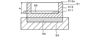
- the round plate 51 includes a circular bottom surface 511 and a side wall 512 surrounding the bottom surface 511. The bottom surface 511 and the top surface 512a of the side wall 512 have a predetermined height relationship.
- the upper surface 512 a of the side wall 512 is provided so as to be parallel to the flat bottom surface 511 and have a height h from the bottom surface 511. Further, the upper surface 512a of the side wall 512 is polished so that light is easily reflected.
- the squeegee 52 forms a coating film 55 having a predetermined thickness t by leveling the flux paste supplied into the round plate 51 from a paste supply line (not shown). As shown in FIG. 3, the squeegee 52 is fixed to the base 53 so as to extend in the radial direction of the round plate 51.
- the round plate 51 rotates accordingly, and the flux paste in the round plate 51 is smoothed by the squeegee 52 to form a coating film 55 having a predetermined thickness t.
- the surface of the coating film 55 is parallel to the bottom surface 511.
- the mounting controller 60 is configured as a microprocessor centered on a CPU 60a, and includes a ROM 60b for storing processing programs, an HDD 60c for storing various data, a RAM 60d used as a work area, and the like. .
- the mounting controller 60 is connected to an input device 60e such as a mouse or a keyboard and a display device 60f such as a liquid crystal display.
- the mounting controller 60 is connected to a feeder controller 47 built in the tape feeder 40, a transfer controller 57 built in the transfer unit 50, and a management computer 90 so as to be capable of bidirectional communication.
- the mounting controller 60 is connected so that control signals can be output to the substrate transfer device 12, the head 18, the X-axis motor 20a, the Y-axis motor 24a, the Z-axis motor 30, the altitude sensor 35, and the parts camera 36. .
- the mounting controller 60 is connected so as to be able to receive signals from the altitude sensor 35 and the parts camera 36.
- the management computer 90 includes a personal computer main body 92, an input device 94, and a display 96, and can input signals from the input device 94 operated by an operator. An image can be output.
- Production job data is stored in the memory of the personal computer main body 92. In the production job data, it is determined which components are mounted on the substrate S in what order in the component mounting machine 10 and how many substrates S are mounted in such a manner.
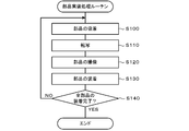
- FIG. 5 is a flowchart of the component mounting process routine.
- the CPU 60a attracts the component P supplied from the tape feeder 40 to the nozzle 28 of the head 18 (step S100). Specifically, the CPU 60a controls the X-axis motor 20a of the X-axis slider 20 and the Y-axis motor 24a of the Y-axis slider 24 to move the nozzle 28 of the head 18 directly above the component suction position of the desired component. . Thereafter, the CPU 60 a controls the Z-axis motor 30 to lower the nozzle 28 and supply negative pressure to the nozzle 28. Thereby, a desired part is adsorbed to the tip of the nozzle 28. Thereafter, the CPU 60a raises the nozzle 28 to the normal position. The normal position is set to a height at which the component does not come into contact with the members constituting the component mounter 10 even if the nozzle 28 that sucks the component moves in the XY direction.
- the CPU 60a transfers the coating film 55 to the connection terminal provided on the lower surface of the component (step S110). Specifically, the CPU 60 a controls the X-axis slider 20 and the Y-axis slider 24 to move the nozzle 28 that attracts components to the tip thereof above a predetermined dip position of the round plate 51. Then, the CPU 60a lowers the nozzle 28 at the dip position, and transfers the coating film 55 to the connection terminal provided on the lower surface of the component adsorbed by the nozzle 28. At this time, the lowering amount of the nozzle 28 is set so that the coating film 55 adheres to the tip of the connection terminal based on the altitude of the surface of the coating film 55. The height of the surface of the coating film 55 is calculated by a pretreatment routine described later.
- the CPU 60a raises the nozzle 28 to the normal position. Further, since the dip position of the coating film 55 is recessed by the transfer, the CPU 60a causes the squeegee 52 to re-form the coating film 55 in preparation for the next transfer.
- the CPU 60a causes the parts camera 36 to image the part adsorbed on the tip of the nozzle 28 (step S120). Specifically, the CPU 60a controls the X-axis slider 20 and the Y-axis slider 24 to move the nozzle 28 that attracts the component at the tip thereof above the parts camera 36, and causes the parts camera 36 to image the component. Then, the CPU 60a confirms that the component is adsorbed to the tip of the nozzle 28 based on the captured image. If the CPU 60a cannot confirm that the component is adsorbed to the tip of the nozzle 28, the process returns to step S100.
- the CPU 60a controls so that the component adsorbed on the tip of the nozzle 28 is mounted at a predetermined position on the substrate S (step S130). Specifically, the CPU 60a controls the X-axis slider 20 and the Y-axis slider 24 to move the component sucked by the nozzle 28 above a predetermined position of the substrate S. Then, the CPU 60a controls the lowering of the nozzle 28 at the predetermined position so that the atmospheric pressure is supplied to the nozzle 28. As a result, the parts adsorbed by the nozzle 28 are separated from each other and mounted at predetermined positions on the substrate S.
- step S140 the CPU 60a determines whether or not the mounting of all the components to be mounted on the board S has been completed. If there is still a part to be mounted on the substrate S in step S140, the CPU 60a repeats the processes in and after step S100 again. On the other hand, if the mounting of all the components is completed in step S140, the CPU 60a ends this routine.
- FIG. 6 is a flowchart of the component mounting process routine.
- the component P shown in FIG. 7 will be described as an example of the component having the connection terminal on the lower surface.
- a plurality of (four) lead terminals L are linearly provided on the lower surface of a rectangular parallelepiped body member.
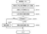
- the CPU 60a moves the altitude sensor 35 above the side wall 512 of the round plate 51 (step S200). Specifically, the CPU 60 a controls the X-axis slider 20 and the Y-axis slider 24 to move the altitude sensor 35 provided on the lower surface of the head 18 above the side wall 512 of the round plate 51. The state at this time is shown in FIG. The height of the lower surface of the head 18 is constant without fluctuation. Therefore, the height of the altitude sensor 35 is also constant.
- the CPU 60a inputs the signal of the altitude sensor 35 (step S210) and recognizes the altitude of the bottom surface 511 of the round plate 51 (step S220). Specifically, the CPU 60a recognizes the distance d from the position of the altitude sensor 35 to the upper surface 512a of the side wall 512 based on the signal of the altitude sensor 35, and the distance d and the height h from the bottom surface 511 to the upper surface 512a, Is used to recognize the height of the bottom surface 511 (for example, the distance from the height sensor 35 to the bottom surface 511).
- the CPU 60a determines whether or not the altitude of the bottom surface 511 is within an allowable range (step S230).
- the allowable range is set to a high numerical range that can be taken by the bottom surface 511 of the round plate 51 when the transfer unit 50 is appropriately mounted on the device pallet 42. For example, when the transfer unit 50 is mounted in a state of being out of the slot of the device pallet 42, the altitude of the bottom surface 511 is outside the allowable range.
- the CPU 60a If the altitude of the bottom surface 511 is out of the allowable range in step S230, the CPU 60a notifies a warning (step S240) and ends this routine.
- the notification of the warning is performed, for example, by displaying a text “The transfer unit is not properly attached” on the display device 60f or by generating a warning sound from the built-in speaker of the component mounter 10.
- the CPU 60a recognizes the altitude of the surface of the coating film 55, stores it in the RAM 60d (step S240), and ends this routine. Specifically, the CPU 60a uses the predetermined thickness t of the coating film 55 in addition to the distance d and the height h described above to determine the altitude of the coating film 55 (for example, the distance from the altitude sensor 35 to the surface of the coating film 55). ) And store it in the RAM 60d.
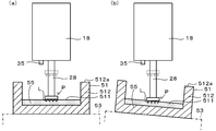
- the CPU 60a sets the lowering amount of the nozzle 28 based on the altitude of the surface of the coating film 55 stored in the RAM 60d when performing the transfer in step S110 of the component mounting processing routine executed thereafter.
- a specific example will be described with reference to FIG.
- the CPU 60 a dips the component P from the position of the dotted line from the position of the lead terminal L to the coating film 55 and transfers the coating film 55 to the tip (solid line component P).
- FIG. 9A is an example in which the round plate 51 is accurately arranged at the design position
- FIG. 9B is an example in which the round plate 51 is arranged at a position lower than the design position.
- the amount by which the nozzle 28 is lowered is larger than that in FIG. 9A.
- the X-axis slider 20, the X-axis motor 20a, the Y-axis slider 24, and the Y-axis motor 24a of this embodiment correspond to the head moving device of the present invention
- the transfer unit 50 corresponds to the transfer device
- the mounting controller 60 controls the control device. It corresponds to.
- the nozzle 28 corresponds to a component holding portion
- the round plate 51 corresponds to a container
- the upper surface 512a of the side wall 512 corresponds to a measurement location.
- the altitude of the bottom surface 511 of the round plate 51 and the altitude of the surface of the coating film 55 are recognized from the altitude of the upper surface 512 a of the side wall 512 of the round plate 51 measured by the altitude sensor 35. Therefore, regardless of whether or not the coating film 55 is formed on the bottom surface 511 of the round plate 51, the altitude of the bottom surface 511 of the round plate 51 and the height of the surface of the coating film 55 can be recognized.
- the round plate 51 (and consequently the transfer unit 50) is properly arranged. If not, a warning is notified to the operator. When the warning is notified, the operator notices that the round plate 51 is not properly arranged, so that the arrangement of the transfer unit 50 can be corrected.
- an altitude at which the lead terminal L of the component P adsorbed by the nozzle 28 is dipped into the coating film 55 is set based on the altitude of the surface of the coating film 55. Therefore, even if the height of the surface of the coating film 55 changes as the height of the bottom surface 511 of the round plate 51 changes, the paste coating film 55 can be reliably transferred to the lead terminals L of the component P. .
- the measurement location of the round plate 51 is set on the upper surface 512a of the side wall 512 surrounding the bottom surface 511. Since the upper surface 512a of the side wall 512 is less likely to adhere paste, the altitude sensor 35 can accurately measure the height of the upper surface 512a of the side wall 512.
- the altitude sensor 35 since an optical sensor is used as the altitude sensor 35, the altitude of the measurement location can be measured without contacting the measurement location of the round plate 51. Therefore, the measurement accuracy is increased.
- one position on the upper surface 512a of the side wall 512 of the round plate 51 is measured by the altitude sensor 35, but the predetermined three positions forming a triangle in the upper surface 512a are measured by the altitude sensor 35. You may measure with. In this way, the altitude of the upper surface 512a and the inclination angle of the upper surface 512a with respect to the horizontal plane can be recognized from the three altitudes. it can. Further, the CPU 60a may issue a warning if the altitude or the inclination angle of the bottom surface 511 exceeds a predetermined allowable range.
- the CPU 60a sets the lowering amount of the nozzle 28 according to the altitude and the tilt angle of the surface of the coating film 55 when performing the transfer in step S110 of the component mounting process routine. You may make it do.
- the CPU 60a determines, based on the inclination angle of the surface of the coating film 55, the position where the tip of the lead terminal L is dipped on the coating film 55 from the position of the dotted line and the coating film 55 is transferred to the tip (solid-line component). Nozzle 28 is lowered until P).
- FIG. 10A is an example in which the round plate 51 is accurately arranged at the design position, and FIG.
- FIG. 10B is an example in which the round plate 51 (transfer unit 50) is inclined with respect to the design position. .
- the coating film 55 since the coating film 55 has high viscosity, it is parallel to the bottom face 511.
- FIG. Note that the measurement points may be a predetermined plurality of points forming a polygon.
- an optical sensor is exemplified as the altitude sensor 35, but the present invention is not particularly limited to this, and may be, for example, an ultrasonic sensor or a contact displacement sensor.
- a contact type displacement sensor it is necessary to make contact with the side wall of the dish, which is the object to be measured, whereas in the case of a non-contact type displacement sensor such as an optical sensor or an ultrasonic sensor, the side wall of the dish Since there is no need to make contact, the non-contact displacement sensor can measure altitude with higher accuracy.
- the measurement location is the upper surface 512a of the side wall 512 of the round plate 51.
- the measurement location is not particularly limited to this.
- a flange is provided along the outer peripheral surface of the side wall 512 of the round plate 51. It is good also considering the upper surface of a collar as a measurement location.
- the height of the bottom surface 511 of the round plate 51 is recognized in step S220 of the preprocessing routine, and the height of the surface of the coating film 55 is recognized in step S250.
- the present invention is not particularly limited to this. Only the height of the bottom surface 511 may be recognized, or only the height of the surface of the coating film 55 may be recognized.
- the transfer unit 50 transfers the flux paste coating film 55 to the lead terminals L of the component P.
- the transfer unit 50 is not particularly limited to this. It may be transferred to the lead terminal L.
- the coating film 55 is transferred to a plurality of lead terminals L provided on the lower surface of the component P.
- the present invention is not particularly limited thereto.
- the coating film 55 may be transferred to the bumps.
- the tape feeder 40 is exemplified as the component supply device.
- the present invention is not particularly limited thereto.
- a tray unit including a magazine in which a large number of trays are stacked in the vertical direction is used as the component supply device. It may be used.
- the head 18 has one nozzle 28, but may have a plurality of nozzles.
- the nozzle 28 that can adsorb the component is illustrated as the component holding unit, but the present invention is not particularly limited thereto, and for example, an arm that can grasp the component may be used.
- the round plate 51 is exemplified as the container of the transfer unit 50, but it is not particularly limited to this, and a plate having a polygonal shape (for example, a square shape) in plan view may be employed.
- the squeegee 52 is fixed and the round plate 51 is rotated.
- the round plate 51 may be fixed and the squeegee 52 may be rotated.
- the descending amount of the nozzle 28 is set based on the altitude of the surface of the coating film 55, but the descending amount of the nozzle 28 may be set based on the altitude of the bottom surface 511 of the round plate 51.
- the height of the bottom surface 511 may be set to the dip height (that is, the lower end height of the lead terminal L of the component P).
- the amount of paste transferred to the component P can be managed by the thickness t of the coating film 55.
- the component mounter of the present invention can be used when mounting electronic components on a board.
Abstract
部品実装機10は、ヘッド18と、ヘッド18を移動させる装置(X軸スライダ20及びY軸スライダ24)と、転写ユニット50と、実装コントローラとを備えている。丸皿51は、ペーストを入れる容器の一例である。この丸皿51の底面と側壁上面とは所定の高さ関係を有している。ヘッド18の下面には、高度センサ35が設けられている。高度センサ35は、測定箇所である丸皿51の側壁上面の高度を測定する。実装コントローラは、高度センサ35によって測定された丸皿51の側壁上面の高度から、丸皿51の底面の高度又は丸皿51に提供される塗膜55の表面の高度を認識する。
Description
本発明は、部品実装機に関する。
部品供給装置から供給される部品をヘッドに設けられたノズルに吸着し、その後ヘッドを基板の上方へ運んでその部品を基板に実装する部品実装機が知られている。その場合、基板の部品実装位置に予めはんだペーストを印刷しておくことがある。近年、部品サイズの極小化に伴い基板に印刷されるペーストも少量になってきたため、設計通りにペーストを印刷することが難しくなっている。こうしたことから、基板の部品実装位置にペーストを印刷する代わりに、部品の下面に設けられた接続端子(BGAなど)にペーストの塗膜を転写させることが行われている。このように部品の接続端子にペーストの塗膜を転写させるにあたり、容器の底面に形成される塗膜の膜厚を算出する部品実装機も開示されている(特許文献1参照)。この部品実装機では、容器に塗膜が存在しない空の状態でその容器の底面の高度を予め計測し、その後、容器の底面に塗膜を形成してその塗膜の表面の高度を計測し、それらの高度の差を膜厚として算出する。
しかしながら、上述した部品実装機では、容器に塗膜が存在しない空の状態でその容器の底面の高度を予め計測する必要があるため、容器の底面に塗膜が形成された後に容器の底面の高度を知ることはできなかった。
本発明はこのような課題に鑑みなされたものであり、容器の底面に塗膜が形成されているか否かにかかわらず、容器の底面の高度又は塗膜の表面の高度を認識できるようにすることを主目的とする。
本発明の部品実装機は、
下面に接続端子を備えた部品を保持可能な部品保持部を備えたヘッドと、
前記ヘッドを移動させるヘッド移動装置と、
底面と該底面とは異なる所定の測定箇所とが所定の高さ関係を有する容器を有し、前記部品の接続端子に転写させるペーストを前記容器の底面に所定厚さの塗膜として提供する転写装置と、
前記ヘッドに設けられ、前記容器の測定箇所の高度を測定可能な高度センサと、
前記転写装置によって提供された前記塗膜が前記部品保持部に保持された前記部品の接続端子に転写されるよう前記ヘッド及び前記ヘッド移動装置を制御する制御装置と、
を備え、
前記制御装置は、前記高度センサによって測定された前記容器の測定箇所の高度から前記容器の底面の高度又は前記塗膜の表面の高度を認識する、
ものである。
この部品実装機では、高度センサによって測定された容器の測定箇所の高度から容器の底面の高度又は塗膜の表面の高度を認識する。容器の測定箇所の高度がわかれば、容器の底面と容器の測定箇所とが有する所定の高さ関係に基づいて、容器の底面の高度を求めることができる。あるいは、容器の測定箇所の高度がわかれば、容器の底面と容器の測定箇所とが有する所定の高さ関係及び塗膜の予め定められた所定厚さに基づいて、塗膜の表面の高度を求めることができる。したがって、容器の底面に塗膜が形成されているか否かにかかわらず、容器の底面の高度又は塗膜の表面の高度を認識することができる。
本発明の部品実装機において、前記制御装置は、前記容器の測定箇所の高度から前記容器の底面の高度を認識し、前記容器の底面の高度に基づいて前記容器が適正に配置されているか否かを判定し、前記容器が適正でなかったならばオペレータに警告を報知してもよい。警告が報知された場合、オペレータは容器が適正に配置されていないことに気づくため、その容器の配置を正すことができる。
本発明の部品実装機において、前記制御装置は、前記容器の測定箇所の高度から前記塗膜の表面の高度を認識し、前記塗膜の表面の高度に基づいて前記部品保持部に保持された前記部品の接続端子を前記塗膜にディップする高度を設定してもよい。こうすれば、容器の底面の高度が変化するのに伴って塗膜の表面の高度が変化したとしても、部品の接続端子にペーストの塗膜を確実に転写することができる。
本発明の部品実装機において、前記容器の測定箇所は、多角形の頂点となるように3箇所以上に設定されていてもよい。こうすれば、容器の底面が傾斜している場合にはその傾斜を認識することができる。
本発明の部品実装機において、前記容器の測定箇所は、前記容器の底面を囲う側壁の上面に設定されていてもよい。容器の底面を囲う側壁の上面はペーストが付着するおそれが少ないため、高度センサによって精度よく容器の測定箇所の高度を測定することができる。
本発明の部品実装機において、前記高度センサは光学センサであってもよい。こうすれば、容器の測定箇所に接触することなくその測定箇所の高度を測定できるため、測定精度が高くなる。
本発明の好適な実施形態を図面を参照しながら以下に説明する。図1は部品実装機10の斜視図、図2は丸皿51及びその周辺部材の断面図、図3は丸皿51の平面図、図4は部品実装機10の電気的接続を示す説明図である。なお、本実施形態において、左右方向(X軸)、前後方向(Y軸)及び上下方向(Z軸)は、図1に示した通りとする。また、図2ではスキージ52の図示を省略した。
部品実装機10は、図1に示すように、基板搬送装置12と、ヘッド18と、ノズル28と、高度センサ35と、パーツカメラ36と、テープフィーダ40と、転写ユニット50と、各種制御を実行する実装コントローラ60(図2参照)とを備えている。
基板搬送装置12は、左右一対のコンベアレール14,14にそれぞれ取り付けられたコンベアベルト16,16(図1では片方のみ図示)により基板Sを左から右へと搬送する。また、基板搬送装置12は、基板Sの下方に配置された支持ピン17により基板Sを下から持ち上げてコンベアレール14,14のガイド部に押し当てることで基板Sを固定し、支持ピン17を下降させることで基板Sの固定を解除する。
ヘッド18は、下面にノズル28を有している。また、ヘッド18は、X軸スライダ20の前面に着脱可能に取り付けられている。X軸スライダ20は、Y軸スライダ24の前面に設けられた左右方向に延びる上下一対のガイドレール22,22にスライド可能に取り付けられている。Y軸スライダ24は、Y軸ボールネジ25に螺合されたナット23と一体化され、前後方向に延びる左右一対のガイドレール26,26にスライド可能に取り付けられている。Y軸ボールネジ25は一端がY軸モータ24aに取り付けられ、他端が自由端となっている。Y軸スライダ24は、こうしたボールネジ機構によってガイドレール26,26に沿ってスライドする。すなわち、Y軸モータ24aが回転すると、Y軸ボールネジ25が回転し、それに伴ってナット23がY軸スライダ24と共にガイドレール26,26に沿ってスライドする。X軸スライダ20は、図示しないが、Y軸スライダ24と同様、X軸モータ20a(図2参照)を備えたボールネジ機構によってガイドレール22,22に沿ってスライドする。ヘッド18は、X軸スライダ20が左右方向に移動するのに伴って左右方向に移動し、Y軸スライダ24が前後方向に移動するのに伴って前後方向に移動する。
ノズル28は、圧力を利用して、ノズル先端に部品を吸着したり、ノズル先端に吸着している部品を離したりするものである。ノズル28は、ヘッド18に内蔵されたZ軸モータ30とZ軸に沿って延びるボールネジ32によって高さが調整される。
高度センサ35は、ヘッド18の下面に取り付けられている。高度センサ35は、ここでは発光素子と受光素子とを備えた光学センサである。この高度センサ35は、発光素子から測定対象物に光を出射し、その測定対象物で反射した光を受光素子で入射することにより、高度センサ35から測定対象物までの距離を測定する。
パーツカメラ36は、デバイスパレット42と基板搬送装置12との間であって左右方向の長さの略中央にて、撮像方向が上向きとなるように設置されている。このパーツカメラ36は、その上方を通過するノズル28に吸着された部品を撮像する。
テープフィーダ40は、部品供給装置の一種であり、部品実装機10の前方のデバイスパレット42に取り付けられている。デバイスパレット42は、上面に多数のスロット(図示せず)を有しており、テープフィーダ40は、そのスロットに差し込まれている。 テープフィーダ40は、テープが巻回されたリール48を回転可能に保持している。テープには、図示しない複数の凹部がテープの長手方向に沿って並ぶように形成されている。各凹部には、部品が収容されている。これらの部品は、テープの表面を覆う図示しないフィルムによって保護されている。テープフィーダ40には、部品吸着位置が定められている。部品吸着位置は、ノズル28が部品を吸着する設計上定められた位置である。テープがテープフィーダ40によって所定量後方へ送られるごとに、テープに収容された部品が順次、部品吸着位置へ配置されるようになっている。部品吸着位置に至った部品は、フィルムが剥がされた状態になっており、ノズル28によって吸着される。
転写ユニット50は、デバイスパレット42のうちテープフィーダ40によって占有されていない複数のスロットに着脱自在に差し込まれている。転写ユニット50は、丸皿51とスキージ52とを備えている。丸皿51は、図2に示すように、ブロック状のベース53に設けられた回転テーブル54の上面に回転テーブル54と一体となって回転するよう固定されている。図3の矢印は丸皿51の回転方向を示す。丸皿51は、円形の底面511とその底面511を囲う側壁512とを備えている。底面511と側壁512の上面512aとは所定の高さ関係を有している。ここでは、側壁512の上面512aは、平坦な底面511と平行で且つ底面511から高さhとなるように設けられている。また、側壁512の上面512aは光が反射しやすいように研磨加工が施されている。スキージ52は、図示しないペースト供給ラインから丸皿51内に供給されたフラックスペーストをならして所定の厚みtの塗膜55を形成するものである。スキージ52は、図3に示すように丸皿51の半径方向に延び出した状態でベース53に固定されている。そのため、回転テーブル54が回転するとそれに伴って丸皿51が回転し、その丸皿51内のフラックスペーストがスキージ52によってならされて所定の厚みtの塗膜55が形成される。この塗膜55の表面は底面511に平行になる。
実装コントローラ60は、図4に示すように、CPU60aを中心とするマイクロプロセッサとして構成されており、処理プログラムを記憶するROM60b、各種データを記憶するHDD60c、作業領域として用いられるRAM60dなどを備えている。また、実装コントローラ60には、マウスやキーボードなどの入力装置60e、液晶ディスプレイなどの表示装置60fが接続されている。この実装コントローラ60は、テープフィーダ40に内蔵されたフィーダコントローラ47、転写ユニット50に内蔵された転写コントローラ57及び管理コンピュータ90と、双方向通信可能なように接続されている。また、実装コントローラ60は、基板搬送装置12、ヘッド18、X軸モータ20a、Y軸モータ24a、Z軸モータ30、高度センサ35及びパーツカメラ36へ制御信号を出力可能なように接続されている。また、実装コントローラ60は、高度センサ35及びパーツカメラ36から信号を受信可能に接続されている。
管理コンピュータ90は、図4に示すように、パソコン本体92と入力デバイス94とディスプレイ96とを備えており、オペレータによって操作される入力デバイス94からの信号を入力可能であり、ディスプレイ96に種々の画像を出力可能である。パソコン本体92のメモリには、生産ジョブデータが記憶されている。生産ジョブデータには、部品実装機10においてどの部品をどういう順番で基板Sへ実装するか、また、そのように実装した基板Sを何枚作製するかなどが定められている。
次に、部品実装機10の実装コントローラ60が生産ジョブに基づいて基板Sへ部品を実装する動作(部品実装処理ルーチン)について説明する。部品実装処理ルーチンのプログラムは実装コントローラ60のROM60bに記憶されている。実装コントローラ60のCPU60aは、部品実装処理の開始が指示されると、ROM60bからこのプログラムを読み出して実行する。図5は部品実装処理ルーチンのフローチャートである。
まず、CPU60aは、ヘッド18のノズル28にテープフィーダ40から供給される部品Pを吸着させる(ステップS100)。具体的には、CPU60aは、X軸スライダ20のX軸モータ20a及びY軸スライダ24のY軸モータ24aを制御してヘッド18のノズル28を所望の部品の部品吸着位置の真上に移動させる。その後、CPU60aは、Z軸モータ30を制御してノズル28を下降させると共にそのノズル28へ負圧が供給されるようにする。これにより、ノズル28の先端に所望の部品が吸着される。その後、CPU60aは、ノズル28を通常位置まで上昇させる。通常位置は、部品を吸着したノズル28がXY方向に移動したとしても部品が部品実装機10を構成する部材と接触しない高さに設定されている。
次に、CPU60aは、部品の下面に設けられた接続端子へ塗膜55を転写させる(ステップS110)。具体的には、CPU60aは、X軸スライダ20及びY軸スライダ24を制御して、先端に部品を吸着したノズル28を丸皿51の所定のディップ位置の上方へ移動させる。そして、CPU60aは、そのディップ位置でノズル28を下降させ、ノズル28に吸着された部品の下面に設けられた接続端子に塗膜55を転写させる。このときのノズル28の下降量は、塗膜55の表面の高度に基づいて接続端子の先端に塗膜55が付着するように設定される。塗膜55の表面の高度は後述する前処理ルーチンで算出される。その後、CPU60aは、ノズル28を通常位置まで上昇させる。また、塗膜55のディップ位置は転写によって凹んでいるため、CPU60aは次回の転写に備えてスキージ52に塗膜55を再形成させる。
次に、CPU60aは、ノズル28の先端に吸着された部品をパーツカメラ36に撮像させる(ステップS120)。具体的には、CPU60aは、X軸スライダ20及びY軸スライダ24を制御して、先端に部品を吸着したノズル28をパーツカメラ36の上方へ移動させ、パーツカメラ36に部品を撮像させる。そして、CPU60aは、撮像された画像に基づいてノズル28の先端に部品が吸着されていることを確認する。なお、CPU60aは、ノズル28の先端に部品が吸着されていることを確認できなかったならば、ステップS100に戻る。
次に、CPU60aは、ノズル28の先端に吸着された部品が基板Sの所定の位置に装着されるよう制御する(ステップS130)。具体的には、CPU60aは、X軸スライダ20及びY軸スライダ24を制御して、ノズル28に吸着された部品を基板Sの所定の位置の上方へ移動させる。そして、CPU60aは、その所定の位置でノズル28を下降させ、そのノズル28へ大気圧が供給されるように制御する。これにより、ノズル28に吸着されていた部品が離間して基板Sの所定の位置に装着される。
次に、CPU60aは、基板Sに装着すべき全部品について装着が完了したか否かを判定する(ステップS140)。ステップS140でまだ基板Sに装着すべき部品が残っていたならば、CPU60aは再びステップS100以降の処理を繰り返す。一方、ステップS140で全部品について装着が完了したならば、CPU60aは本ルーチンを終了する。
次に、部品実装機10の実装コントローラ60が実行する前処理ルーチンについて説明する。前処理ルーチンのプログラムは実装コントローラ60のROM60bに記憶されている。実装コントローラ60のCPU60aは、上述した部品実装処理ルーチンを実行する前に、ROM60bからこの前処理ルーチンのプログラムを読み出して実行する。図6は部品実装処理ルーチンのフローチャートである。以下には、下面に接続端子を有する部品として、図7に示す部品Pを例示して説明する。部品Pは、直方体形状の本体部材の下面に複数(4本)のリード端子Lが直線状に設けられているものである。
まず、CPU60aは、高度センサ35を丸皿51の側壁512の上方へ移動させる(ステップS200)。具体的には、CPU60aは、X軸スライダ20及びY軸スライダ24を制御して、ヘッド18の下面に設けられた高度センサ35を丸皿51の側壁512の上方へ移動させる。このときの様子を図8に示す。なお、ヘッド18の下面の高さは変動することなく一定である。そのため、高度センサ35の高さも一定である。
次に、CPU60aは、高度センサ35の信号を入力し(ステップS210)、丸皿51の底面511の高度を認識する(ステップS220)。具体的には、CPU60aは、高度センサ35の信号に基づいて高度センサ35の位置から側壁512の上面512aまでの距離dを認識し、その距離dと底面511から上面512aまでの高さhとを用いて底面511の高度(例えば高度センサ35から底面511までの距離)を認識する。
次に、CPU60aは、底面511の高度が許容範囲内か否かを判定する(ステップS230)。ここでは、許容範囲は、転写ユニット50がデバイスパレット42に適切に装着されている場合に丸皿51の底面511が取り得る高度の数値範囲に設定されている。例えば、転写ユニット50がデバイスパレット42のスロットから外れた状態で装着されている場合には、底面511の高度は許容範囲外になる。
ステップS230で底面511の高度が許容範囲外だったならば、CPU60aは警告を報知し(ステップS240)、本ルーチンを終了する。警告の報知は、例えば表示装置60fに「転写ユニットが適切に装着されていません」と文字表示したり部品実装機10の内蔵スピーカから音声で警告音を発生したりすることにより行う。
一方、ステップS230で底面511の高度が許容範囲内だったならば、CPU60aは塗膜55の表面の高度を認識し、それをRAM60dに保存し(ステップS240)、本ルーチンを終了する。具体的には、CPU60aは、上述の距離d及び高さhのほかに塗膜55の所定の厚みtを用いて、塗膜55の高度(例えば高度センサ35から塗膜55の表面までの距離)を認識し、それをRAM60dに保存する。
CPU60aは、この後に実行される部品実装処理ルーチンのステップS110で転写を行う際に、ノズル28の下降量をRAM60dに保存した塗膜55の表面の高度に基づいて設定する。その具体例を図9を用いて説明する。ノズル28が丸皿51の所定のディップ位置の上方に配置されたとき、部品Pは、点線で示すように、ヘッド18がXY方向に移動したとしても部品実装機10を構成する各種部材に干渉しない高さに位置決めされている。CPU60aは、塗膜55の表面の高度に基づいて、部品Pを点線の位置からリード端子Lの先端が塗膜55にディップされてその先端に塗膜55が転写される位置(実線の部品Pを参照)までノズル28を下降させる。図9(a)は丸皿51が設計位置に精度よく配置されている例であり、図9(b)は丸皿51が設計位置より低い位置に配置されている例である。図9(b)では、図9(a)に比べて塗膜55の表面が低い位置にあるため、ノズル28の下降量は図9(a)よりも大きくなる。
ここで、本実施形態の構成要素と本発明の構成要素との対応関係について説明する。本実施形態のX軸スライダ20、X軸モータ20a、Y軸スライダ24及びY軸モータ24aが本発明のヘッド移動装置に相当し、転写ユニット50が転写装置に相当し、実装コントローラ60が制御装置に相当する。また、ノズル28が部品保持部に相当し、丸皿51が容器に相当し、側壁512の上面512aが測定箇所に相当する。
以上説明した部品実装機10では、高度センサ35によって測定された丸皿51の側壁512の上面512aの高度から、丸皿51の底面511の高度や塗膜55の表面の高度を認識する。そのため、丸皿51の底面511に塗膜55が形成されているか否かにかかわらず、丸皿51の底面511の高度や塗膜55の表面の高度を認識することができる。
また、丸皿51の底面511の高度に基づいて丸皿51(ひいては転写ユニット50)が適正に配置されているか否かを判定し、適正でなかったならばオペレータに警告を報知する。警告が報知された場合、オペレータは丸皿51が適正に配置されていないことに気づくため、転写ユニット50の配置を正すことができる。
更に、塗膜55の表面の高度に基づいてノズル28に吸着された部品Pのリード端子Lを塗膜55にディップする高度を設定する。そのため、丸皿51の底面511の高度が変化するのに伴って塗膜55の表面の高度が変化したとしても、部品Pのリード端子Lにペーストの塗膜55を確実に転写することができる。
更にまた、丸皿51の測定箇所は、底面511を囲う側壁512の上面512aに設定されている。この側壁512の上面512aはペーストが付着するおそれが少ないため、高度センサ35によって精度よく側壁512の上面512aの高度を測定することができる。
そしてまた、高度センサ35として光学センサを用いているため、丸皿51の測定箇所に接触することなくその測定箇所の高度を測定できる。そのため、測定精度が高くなる。
なお、本発明は上述した実施形態に何ら限定されることはなく、本発明の技術的範囲に属する限り種々の態様で実施し得ることはいうまでもない。
例えば、上述した実施形態では、前処理ルーチンにおいて、丸皿51の側壁512の上面512aの1箇所を高度センサ35で測定したが、上面512aのうち三角形を形成する所定の3箇所を高度センサ35で測定してもよい。こうすれば、その3箇所の高度から上面512aの高度や上面512aの水平面に対する傾斜角を認識することができ、ひいては底面511及び塗膜55の表面の高度や水平面に対する傾斜角を認識することができる。また、CPU60aは、底面511の高度や傾斜角が予め定めた許容範囲を超えていたならば、警告を報知するようにしてもよい。一方、CPU60aは、傾斜角が許容範囲内だったならば、部品実装処理ルーチンのステップS110で転写を行う際に、ノズル28の下降量を塗膜55の表面の高度や傾斜角に応じて設定するようにしてもよい。その具体例を図10を用いて説明する。CPU60aは、塗膜55の表面の傾斜角に基づいて、部品Pを点線の位置からリード端子Lの先端が塗膜55にディップされてその先端に塗膜55が転写される位置(実線の部品Pを参照)までノズル28を下降させる。図10(a)は丸皿51が設計位置に精度よく配置されている例であり、図10(b)は丸皿51(転写ユニット50)が設計位置より傾いて配置されている例である。図10(b)において、塗膜55は粘度が高いため底面511に平行になっている。なお、測定箇所は多角形を形成する所定の複数箇所としてもよい。
上述した実施形態では、高度センサ35として光学センサを例示したが、特にこれに限定されるものではなく、例えば超音波センサでもよいし、接触式変位センサでもよい。但し、接触式変位センサの場合には測定対象物である皿の側壁に接触させる必要があるのに対して、光学センサや超音波センサなどの非接触式変位センサの場合には皿の側壁に接触させる必要がないため、非接触式変位センサの方が精度よく高度を測定することができる。
上述した実施形態では、測定箇所を丸皿51の側壁512の上面512aとしたが、特にこれに限定されるものではなく、例えば丸皿51の側壁512の外周面に沿ってツバを設け、そのツバの上面を測定箇所としてもよい。
上述した実施形態では、前処理ルーチンのステップS220で丸皿51の底面511の高度を認識し、ステップS250で塗膜55の表面の高度を認識したが、特にこれに限定されるものではなく、底面511の高度のみを認識するようにしてもよいし、塗膜55の表面の高度のみを認識するようにしてもよい。
上述した実施形態では、転写ユニット50はフラックスペーストの塗膜55を部品Pのリード端子Lに転写するものとしたが、特にこれに限定されるものではなく、例えばはんだペーストの塗膜を部品Pのリード端子Lに転写するものとしてもよい。
上述した実施形態では、部品Pの下面に複数設けれたリード端子Lに塗膜55を転写する場合を例示したが、特にこれに限定されるものではなく、例えばリード端子Lの代わりに半球状のバンプに塗膜55を転写するようにしてもよい。
上述した実施形態では、部品供給装置としてテープフィーダ40を例示したが、特にこれに限定されるものではなく、例えば部品供給装置として多数のトレイが上下方向に積層されたマガジンを備えたトレイユニットを用いてもよい。
上述した実施形態では、ヘッド18は1つのノズル28を有するものとしたが、複数のノズルを有するものとしてもよい。
上述した実施形態では、部品保持部として部品を吸着可能なノズル28を例示したが、特にこれに限定されるものではなく、例えば部品を把持可能なアームを用いてもよい。
上述した実施形態では、転写ユニット50の容器として丸皿51を例示したが、特にこれに限定されるものではなく、平面視が多角形状(例えば四角形状)の皿を採用してもよい。
上述した実施形態では、スキージ52を固定して丸皿51を回転させる構成としたが、丸皿51を固定してスキージ52を回転させる構成としてもよい。
上述した実施形態では、ノズル28の下降量を塗膜55の表面の高度に基づいて設定したが、ノズル28の下降量を丸皿51の底面511の高度に基づいて設定してもよい。例えば、底面511の高度をディップ高さ(つまり部品Pのリード端子Lの下端高さ)となるようにしてもよい。その場合、部品Pへのペーストの転写量は塗膜55の厚みtによって管理することができる。
本発明の部品実装機は、基板に電子部品を実装する際に利用可能である。
10 部品実装機、12 基板搬送装置、14 コンベアレール、16 コンベアベルト、17 支持ピン、18 ヘッド、20 X軸スライダ、20a X軸モータ、22 ガイドレール、23 ナット、24 Y軸スライダ、24a Y軸モータ、25 Y軸ボールネジ、26 ガイドレール、28 ノズル、30 Z軸モータ、32 ボールネジ、35 高度センサ、36 パーツカメラ、40 テープフィーダ、42 デバイスパレット、47 フィーダコントローラ、48 リール、50 転写ユニット、51 丸皿、511 底面、512 側壁、512a 上面、52 スキージ、53 ベース、54 回転テーブル、55 塗膜、57 転写コントローラ、60 実装コントローラ、60a CPU、60b ROM、60c HDD、60d RAM、60e 入力装置、60f 表示装置、90 管理コンピュータ、92 パソコン本体、94 入力デバイス、96 ディスプレイ。
Claims (6)
- 下面に接続端子を備えた部品を保持可能な部品保持部を備えたヘッドと、
前記ヘッドを移動させるヘッド移動装置と、
底面と該底面とは異なる所定の測定箇所とが所定の高さ関係を有する容器を有し、前記部品の接続端子に転写させるペーストを前記容器の底面に所定厚さの塗膜として提供する転写装置と、
前記ヘッドに設けられ、前記容器の測定箇所の高度を測定可能な高度センサと、
前記転写装置によって提供された前記塗膜が前記部品保持部に保持された前記部品の接続端子に転写されるよう前記ヘッド及び前記ヘッド移動装置を制御する制御装置と、
を備え、
前記制御装置は、前記高度センサによって測定された前記容器の測定箇所の高度から前記容器の底面の高度又は前記塗膜の表面の高度を認識する、
部品実装機。 - 前記制御装置は、前記容器の測定箇所の高度から前記容器の底面の高度を認識し、前記容器の底面の高度に基づいて前記容器が適正に配置されているか否かを判定し、前記容器が適正でなかったならばオペレータに警告を報知する、
請求項1に記載の部品実装機。 - 前記制御装置は、前記容器の測定箇所の高度から前記塗膜の表面の高度を認識し、前記塗膜の表面の高度に基づいて前記部品保持部に保持された前記部品の接続端子を前記塗膜にディップする高度を設定する、
請求項1又は2に記載の部品実装機。 - 前記容器の測定箇所は、多角形の頂点となるように3箇所以上に設定されている、
請求項1~3のいずれか1項に記載の部品実装機。 - 前記容器の測定箇所は、前記容器の底面を囲う側壁の上面に設定されている、
請求項1~4のいずれか1項に記載の部品実装機。 - 前記高度センサは、光学センサである、
請求項1~5のいずれか1項に記載の部品実装機。
Priority Applications (5)
| Application Number | Priority Date | Filing Date | Title |
|---|---|---|---|
| US16/333,464 US11503752B2 (en) | 2016-09-20 | 2016-09-20 | Component mounting machine |
| JP2018540513A JP6804544B2 (ja) | 2016-09-20 | 2016-09-20 | 部品実装機 |
| CN201680089199.7A CN109691243B (zh) | 2016-09-20 | 2016-09-20 | 元件安装机 |
| EP16916740.0A EP3518632B1 (en) | 2016-09-20 | 2016-09-20 | Component mounting machine |
| PCT/JP2016/077671 WO2018055669A1 (ja) | 2016-09-20 | 2016-09-20 | 部品実装機 |
Applications Claiming Priority (1)
| Application Number | Priority Date | Filing Date | Title |
|---|---|---|---|
| PCT/JP2016/077671 WO2018055669A1 (ja) | 2016-09-20 | 2016-09-20 | 部品実装機 |
Publications (1)
| Publication Number | Publication Date |
|---|---|
| WO2018055669A1 true WO2018055669A1 (ja) | 2018-03-29 |
Family
ID=61690225
Family Applications (1)
| Application Number | Title | Priority Date | Filing Date |
|---|---|---|---|
| PCT/JP2016/077671 WO2018055669A1 (ja) | 2016-09-20 | 2016-09-20 | 部品実装機 |
Country Status (5)
| Country | Link |
|---|---|
| US (1) | US11503752B2 (ja) |
| EP (1) | EP3518632B1 (ja) |
| JP (1) | JP6804544B2 (ja) |
| CN (1) | CN109691243B (ja) |
| WO (1) | WO2018055669A1 (ja) |
Cited By (1)
| Publication number | Priority date | Publication date | Assignee | Title |
|---|---|---|---|---|
| WO2021130975A1 (ja) * | 2019-12-26 | 2021-07-01 | 株式会社Fuji | 部品実装機及び転写材転写方法 |
Families Citing this family (1)
| Publication number | Priority date | Publication date | Assignee | Title |
|---|---|---|---|---|
| JP2021053718A (ja) * | 2019-09-27 | 2021-04-08 | ファナック株式会社 | ワークを検出する検出システム |
Citations (4)
| Publication number | Priority date | Publication date | Assignee | Title |
|---|---|---|---|---|
| JP2000340933A (ja) * | 1999-05-27 | 2000-12-08 | Hitachi Via Mechanics Ltd | 導電性ボール搭載装置におけるフラックス供給装置 |
| JP2002185117A (ja) * | 2000-12-11 | 2002-06-28 | Matsushita Electric Ind Co Ltd | 粘性流体転写装置及び転写方法、電子部品実装装置及び実装方法、並びに半導体装置 |
| JP2005329274A (ja) * | 2004-05-18 | 2005-12-02 | Matsushita Electric Ind Co Ltd | 膜形成装置 |
| JP2014078581A (ja) | 2012-10-10 | 2014-05-01 | Panasonic Corp | 電子部品実装装置および転写膜厚検出方法 |
Family Cites Families (7)
| Publication number | Priority date | Publication date | Assignee | Title |
|---|---|---|---|---|
| JP3295529B2 (ja) * | 1994-05-06 | 2002-06-24 | 松下電器産業株式会社 | Ic部品実装方法及び装置 |
| JP3714097B2 (ja) * | 2000-03-21 | 2005-11-09 | 松下電器産業株式会社 | バンプ付電子部品の実装方法 |
| JP5861040B2 (ja) * | 2012-12-27 | 2016-02-16 | パナソニックIpマネジメント株式会社 | ペースト転写ユニットおよび電子部品実装装置ならびに転写膜厚測定方法 |
| CN105379447B (zh) | 2013-07-31 | 2019-03-15 | 株式会社富士 | 电子元件安装装置及安装方法 |
| US10858235B2 (en) * | 2015-07-06 | 2020-12-08 | Lg Innotek Co., Ltd. | Automatic water supply device |
| WO2017063953A1 (en) * | 2015-10-15 | 2017-04-20 | Nestec S.A. | Beverage preparation machine |
| JP6778261B2 (ja) * | 2016-05-31 | 2020-10-28 | 株式会社Fuji | 部品供給装置 |
-
2016
- 2016-09-20 JP JP2018540513A patent/JP6804544B2/ja active Active
- 2016-09-20 US US16/333,464 patent/US11503752B2/en active Active
- 2016-09-20 CN CN201680089199.7A patent/CN109691243B/zh active Active
- 2016-09-20 WO PCT/JP2016/077671 patent/WO2018055669A1/ja unknown
- 2016-09-20 EP EP16916740.0A patent/EP3518632B1/en active Active
Patent Citations (4)
| Publication number | Priority date | Publication date | Assignee | Title |
|---|---|---|---|---|
| JP2000340933A (ja) * | 1999-05-27 | 2000-12-08 | Hitachi Via Mechanics Ltd | 導電性ボール搭載装置におけるフラックス供給装置 |
| JP2002185117A (ja) * | 2000-12-11 | 2002-06-28 | Matsushita Electric Ind Co Ltd | 粘性流体転写装置及び転写方法、電子部品実装装置及び実装方法、並びに半導体装置 |
| JP2005329274A (ja) * | 2004-05-18 | 2005-12-02 | Matsushita Electric Ind Co Ltd | 膜形成装置 |
| JP2014078581A (ja) | 2012-10-10 | 2014-05-01 | Panasonic Corp | 電子部品実装装置および転写膜厚検出方法 |
Non-Patent Citations (1)
| Title |
|---|
| See also references of EP3518632A4 |
Cited By (3)
| Publication number | Priority date | Publication date | Assignee | Title |
|---|---|---|---|---|
| WO2021130975A1 (ja) * | 2019-12-26 | 2021-07-01 | 株式会社Fuji | 部品実装機及び転写材転写方法 |
| JPWO2021130975A1 (ja) * | 2019-12-26 | 2021-07-01 | ||
| JP7332720B2 (ja) | 2019-12-26 | 2023-08-23 | 株式会社Fuji | 部品実装機及び転写材転写方法 |
Also Published As
| Publication number | Publication date |
|---|---|
| CN109691243A (zh) | 2019-04-26 |
| JP6804544B2 (ja) | 2020-12-23 |
| CN109691243B (zh) | 2022-04-26 |
| EP3518632B1 (en) | 2021-09-15 |
| EP3518632A4 (en) | 2019-09-25 |
| US11503752B2 (en) | 2022-11-15 |
| JPWO2018055669A1 (ja) | 2019-07-04 |
| EP3518632A1 (en) | 2019-07-31 |
| US20190261541A1 (en) | 2019-08-22 |
Similar Documents
| Publication | Publication Date | Title |
|---|---|---|
| JP2004179636A (ja) | 電子部品実装装置における校正方法および装置 | |
| EP3032933B1 (en) | Electronic component mounting machine and transfer confirmation method | |
| JP6355097B2 (ja) | 実装システム、キャリブレーション方法及びプログラム | |
| US10588251B2 (en) | Mounting target working device | |
| WO2018131143A1 (ja) | 被実装物作業装置 | |
| WO2018055669A1 (ja) | 部品実装機 | |
| JP6169708B2 (ja) | 製造作業機 | |
| TWI423354B (zh) | 導電球安裝裝置 | |
| JP2003289199A (ja) | 対基板作業システム | |
| JP6796363B2 (ja) | 部品実装機 | |
| WO2018163323A1 (ja) | 3次元実装関連装置 | |
| JP6178579B2 (ja) | 部品実装装置及び部品実装方法 | |
| JP6896943B2 (ja) | 情報処理装置、作業システム、および決定方法 | |
| JP4832112B2 (ja) | 電子部品装着装置及び電子部品装着方法 | |
| JP2006339495A (ja) | 電子部品実装装置における部品厚み計測治具および部品厚み計測方法 | |
| JP2007294777A (ja) | フラックス転写装置 | |
| JP4722741B2 (ja) | 電子部品装着方法及び電子部品装着装置 | |
| JPWO2015063950A1 (ja) | 回路基材支持システム | |
| JP2024014297A (ja) | 部品実装装置 | |
| JP2024008490A (ja) | 到達判定装置および到達判定方法 | |
| WO2020075256A1 (ja) | 作業機 |
Legal Events
| Date | Code | Title | Description |
|---|---|---|---|
| 121 | Ep: the epo has been informed by wipo that ep was designated in this application |
Ref document number: 16916740 Country of ref document: EP Kind code of ref document: A1 |
|
| ENP | Entry into the national phase |
Ref document number: 2018540513 Country of ref document: JP Kind code of ref document: A |
|
| NENP | Non-entry into the national phase |
Ref country code: DE |
|
| ENP | Entry into the national phase |
Ref document number: 2016916740 Country of ref document: EP Effective date: 20190423 |