WO2018047871A1 - アルミナ粉末、アルミナスラリー、アルミナ含有コート層、積層分離膜及び二次電池 - Google Patents
アルミナ粉末、アルミナスラリー、アルミナ含有コート層、積層分離膜及び二次電池 Download PDFInfo
- Publication number
- WO2018047871A1 WO2018047871A1 PCT/JP2017/032150 JP2017032150W WO2018047871A1 WO 2018047871 A1 WO2018047871 A1 WO 2018047871A1 JP 2017032150 W JP2017032150 W JP 2017032150W WO 2018047871 A1 WO2018047871 A1 WO 2018047871A1
- Authority
- WO
- WIPO (PCT)
- Prior art keywords
- alumina
- coat layer
- separation membrane
- alumina powder
- electrode
- Prior art date
- Legal status (The legal status is an assumption and is not a legal conclusion. Google has not performed a legal analysis and makes no representation as to the accuracy of the status listed.)
- Ceased
Links
Images


Classifications
-
- H—ELECTRICITY
- H01—ELECTRIC ELEMENTS
- H01M—PROCESSES OR MEANS, e.g. BATTERIES, FOR THE DIRECT CONVERSION OF CHEMICAL ENERGY INTO ELECTRICAL ENERGY
- H01M4/00—Electrodes
- H01M4/02—Electrodes composed of, or comprising, active material
- H01M4/62—Selection of inactive substances as ingredients for active masses, e.g. binders, fillers
- H01M4/628—Inhibitors, e.g. gassing inhibitors, corrosion inhibitors
-
- H—ELECTRICITY
- H01—ELECTRIC ELEMENTS
- H01M—PROCESSES OR MEANS, e.g. BATTERIES, FOR THE DIRECT CONVERSION OF CHEMICAL ENERGY INTO ELECTRICAL ENERGY
- H01M10/00—Secondary cells; Manufacture thereof
- H01M10/42—Methods or arrangements for servicing or maintenance of secondary cells or secondary half-cells
- H01M10/4235—Safety or regulating additives or arrangements in electrodes, separators or electrolyte
-
- B—PERFORMING OPERATIONS; TRANSPORTING
- B01—PHYSICAL OR CHEMICAL PROCESSES OR APPARATUS IN GENERAL
- B01D—SEPARATION
- B01D67/00—Processes specially adapted for manufacturing semi-permeable membranes for separation processes or apparatus
- B01D67/0081—After-treatment of organic or inorganic membranes
- B01D67/0088—Physical treatment with compounds, e.g. swelling, coating or impregnation
-
- B—PERFORMING OPERATIONS; TRANSPORTING
- B01—PHYSICAL OR CHEMICAL PROCESSES OR APPARATUS IN GENERAL
- B01D—SEPARATION
- B01D69/00—Semi-permeable membranes for separation processes or apparatus characterised by their form, structure or properties; Manufacturing processes specially adapted therefor
- B01D69/12—Composite membranes; Ultra-thin membranes
- B01D69/1213—Laminated layers
-
- B—PERFORMING OPERATIONS; TRANSPORTING
- B01—PHYSICAL OR CHEMICAL PROCESSES OR APPARATUS IN GENERAL
- B01D—SEPARATION
- B01D71/00—Semi-permeable membranes for separation processes or apparatus characterised by the material; Manufacturing processes specially adapted therefor
- B01D71/02—Inorganic material
- B01D71/024—Oxides
- B01D71/025—Aluminium oxide
-
- C—CHEMISTRY; METALLURGY
- C01—INORGANIC CHEMISTRY
- C01F—COMPOUNDS OF THE METALS BERYLLIUM, MAGNESIUM, ALUMINIUM, CALCIUM, STRONTIUM, BARIUM, RADIUM, THORIUM, OR OF THE RARE-EARTH METALS
- C01F7/00—Compounds of aluminium
- C01F7/02—Aluminium oxide; Aluminium hydroxide; Aluminates
-
- C—CHEMISTRY; METALLURGY
- C01—INORGANIC CHEMISTRY
- C01F—COMPOUNDS OF THE METALS BERYLLIUM, MAGNESIUM, ALUMINIUM, CALCIUM, STRONTIUM, BARIUM, RADIUM, THORIUM, OR OF THE RARE-EARTH METALS
- C01F7/00—Compounds of aluminium
- C01F7/02—Aluminium oxide; Aluminium hydroxide; Aluminates
- C01F7/30—Preparation of aluminium oxide or hydroxide by thermal decomposition or by hydrolysis or oxidation of aluminium compounds
-
- H—ELECTRICITY
- H01—ELECTRIC ELEMENTS
- H01M—PROCESSES OR MEANS, e.g. BATTERIES, FOR THE DIRECT CONVERSION OF CHEMICAL ENERGY INTO ELECTRICAL ENERGY
- H01M4/00—Electrodes
- H01M4/02—Electrodes composed of, or comprising, active material
- H01M4/36—Selection of substances as active materials, active masses, active liquids
- H01M4/362—Composites
- H01M4/366—Composites as layered products
-
- H—ELECTRICITY
- H01—ELECTRIC ELEMENTS
- H01M—PROCESSES OR MEANS, e.g. BATTERIES, FOR THE DIRECT CONVERSION OF CHEMICAL ENERGY INTO ELECTRICAL ENERGY
- H01M4/00—Electrodes
- H01M4/02—Electrodes composed of, or comprising, active material
- H01M4/62—Selection of inactive substances as ingredients for active masses, e.g. binders, fillers
- H01M4/621—Binders
- H01M4/622—Binders being polymers
-
- H—ELECTRICITY
- H01—ELECTRIC ELEMENTS
- H01M—PROCESSES OR MEANS, e.g. BATTERIES, FOR THE DIRECT CONVERSION OF CHEMICAL ENERGY INTO ELECTRICAL ENERGY
- H01M4/00—Electrodes
- H01M4/02—Electrodes composed of, or comprising, active material
- H01M4/62—Selection of inactive substances as ingredients for active masses, e.g. binders, fillers
- H01M4/621—Binders
- H01M4/622—Binders being polymers
- H01M4/623—Binders being polymers fluorinated polymers
-
- H—ELECTRICITY
- H01—ELECTRIC ELEMENTS
- H01M—PROCESSES OR MEANS, e.g. BATTERIES, FOR THE DIRECT CONVERSION OF CHEMICAL ENERGY INTO ELECTRICAL ENERGY
- H01M50/00—Constructional details or processes of manufacture of the non-active parts of electrochemical cells other than fuel cells, e.g. hybrid cells
- H01M50/40—Separators; Membranes; Diaphragms; Spacing elements inside cells
- H01M50/409—Separators, membranes or diaphragms characterised by the material
- H01M50/446—Composite material consisting of a mixture of organic and inorganic materials
-
- H—ELECTRICITY
- H01—ELECTRIC ELEMENTS
- H01M—PROCESSES OR MEANS, e.g. BATTERIES, FOR THE DIRECT CONVERSION OF CHEMICAL ENERGY INTO ELECTRICAL ENERGY
- H01M50/00—Constructional details or processes of manufacture of the non-active parts of electrochemical cells other than fuel cells, e.g. hybrid cells
- H01M50/40—Separators; Membranes; Diaphragms; Spacing elements inside cells
- H01M50/409—Separators, membranes or diaphragms characterised by the material
- H01M50/449—Separators, membranes or diaphragms characterised by the material having a layered structure
- H01M50/451—Separators, membranes or diaphragms characterised by the material having a layered structure comprising layers of only organic material and layers containing inorganic material
-
- H—ELECTRICITY
- H01—ELECTRIC ELEMENTS
- H01M—PROCESSES OR MEANS, e.g. BATTERIES, FOR THE DIRECT CONVERSION OF CHEMICAL ENERGY INTO ELECTRICAL ENERGY
- H01M50/00—Constructional details or processes of manufacture of the non-active parts of electrochemical cells other than fuel cells, e.g. hybrid cells
- H01M50/50—Current conducting connections for cells or batteries
- H01M50/572—Means for preventing undesired use or discharge
- H01M50/574—Devices or arrangements for the interruption of current
- H01M50/581—Devices or arrangements for the interruption of current in response to temperature
-
- C—CHEMISTRY; METALLURGY
- C01—INORGANIC CHEMISTRY
- C01P—INDEXING SCHEME RELATING TO STRUCTURAL AND PHYSICAL ASPECTS OF SOLID INORGANIC COMPOUNDS
- C01P2004/00—Particle morphology
- C01P2004/51—Particles with a specific particle size distribution
-
- C—CHEMISTRY; METALLURGY
- C01—INORGANIC CHEMISTRY
- C01P—INDEXING SCHEME RELATING TO STRUCTURAL AND PHYSICAL ASPECTS OF SOLID INORGANIC COMPOUNDS
- C01P2006/00—Physical properties of inorganic compounds
- C01P2006/11—Powder tap density
-
- C—CHEMISTRY; METALLURGY
- C01—INORGANIC CHEMISTRY
- C01P—INDEXING SCHEME RELATING TO STRUCTURAL AND PHYSICAL ASPECTS OF SOLID INORGANIC COMPOUNDS
- C01P2006/00—Physical properties of inorganic compounds
- C01P2006/12—Surface area
-
- C—CHEMISTRY; METALLURGY
- C01—INORGANIC CHEMISTRY
- C01P—INDEXING SCHEME RELATING TO STRUCTURAL AND PHYSICAL ASPECTS OF SOLID INORGANIC COMPOUNDS
- C01P2006/00—Physical properties of inorganic compounds
- C01P2006/20—Powder free flowing behaviour
-
- C—CHEMISTRY; METALLURGY
- C01—INORGANIC CHEMISTRY
- C01P—INDEXING SCHEME RELATING TO STRUCTURAL AND PHYSICAL ASPECTS OF SOLID INORGANIC COMPOUNDS
- C01P2006/00—Physical properties of inorganic compounds
- C01P2006/32—Thermal properties
-
- H—ELECTRICITY
- H01—ELECTRIC ELEMENTS
- H01M—PROCESSES OR MEANS, e.g. BATTERIES, FOR THE DIRECT CONVERSION OF CHEMICAL ENERGY INTO ELECTRICAL ENERGY
- H01M10/00—Secondary cells; Manufacture thereof
- H01M10/05—Accumulators with non-aqueous electrolyte
- H01M10/056—Accumulators with non-aqueous electrolyte characterised by the materials used as electrolytes, e.g. mixed inorganic/organic electrolytes
-
- H—ELECTRICITY
- H01—ELECTRIC ELEMENTS
- H01M—PROCESSES OR MEANS, e.g. BATTERIES, FOR THE DIRECT CONVERSION OF CHEMICAL ENERGY INTO ELECTRICAL ENERGY
- H01M4/00—Electrodes
- H01M4/02—Electrodes composed of, or comprising, active material
- H01M2004/021—Physical characteristics, e.g. porosity, surface area
-
- H—ELECTRICITY
- H01—ELECTRIC ELEMENTS
- H01M—PROCESSES OR MEANS, e.g. BATTERIES, FOR THE DIRECT CONVERSION OF CHEMICAL ENERGY INTO ELECTRICAL ENERGY
- H01M2200/00—Safety devices for primary or secondary batteries
- H01M2200/10—Temperature sensitive devices
-
- H—ELECTRICITY
- H01—ELECTRIC ELEMENTS
- H01M—PROCESSES OR MEANS, e.g. BATTERIES, FOR THE DIRECT CONVERSION OF CHEMICAL ENERGY INTO ELECTRICAL ENERGY
- H01M4/00—Electrodes
- H01M4/02—Electrodes composed of, or comprising, active material
- H01M4/13—Electrodes for accumulators with non-aqueous electrolyte, e.g. for lithium-accumulators; Processes of manufacture thereof
-
- H—ELECTRICITY
- H01—ELECTRIC ELEMENTS
- H01M—PROCESSES OR MEANS, e.g. BATTERIES, FOR THE DIRECT CONVERSION OF CHEMICAL ENERGY INTO ELECTRICAL ENERGY
- H01M50/00—Constructional details or processes of manufacture of the non-active parts of electrochemical cells other than fuel cells, e.g. hybrid cells
- H01M50/40—Separators; Membranes; Diaphragms; Spacing elements inside cells
- H01M50/489—Separators, membranes, diaphragms or spacing elements inside the cells, characterised by their physical properties, e.g. swelling degree, hydrophilicity or shut down properties
-
- H—ELECTRICITY
- H01—ELECTRIC ELEMENTS
- H01M—PROCESSES OR MEANS, e.g. BATTERIES, FOR THE DIRECT CONVERSION OF CHEMICAL ENERGY INTO ELECTRICAL ENERGY
- H01M50/00—Constructional details or processes of manufacture of the non-active parts of electrochemical cells other than fuel cells, e.g. hybrid cells
- H01M50/40—Separators; Membranes; Diaphragms; Spacing elements inside cells
- H01M50/489—Separators, membranes, diaphragms or spacing elements inside the cells, characterised by their physical properties, e.g. swelling degree, hydrophilicity or shut down properties
- H01M50/491—Porosity
-
- Y—GENERAL TAGGING OF NEW TECHNOLOGICAL DEVELOPMENTS; GENERAL TAGGING OF CROSS-SECTIONAL TECHNOLOGIES SPANNING OVER SEVERAL SECTIONS OF THE IPC; TECHNICAL SUBJECTS COVERED BY FORMER USPC CROSS-REFERENCE ART COLLECTIONS [XRACs] AND DIGESTS
- Y02—TECHNOLOGIES OR APPLICATIONS FOR MITIGATION OR ADAPTATION AGAINST CLIMATE CHANGE
- Y02E—REDUCTION OF GREENHOUSE GAS [GHG] EMISSIONS, RELATED TO ENERGY GENERATION, TRANSMISSION OR DISTRIBUTION
- Y02E60/00—Enabling technologies; Technologies with a potential or indirect contribution to GHG emissions mitigation
- Y02E60/10—Energy storage using batteries
-
- Y—GENERAL TAGGING OF NEW TECHNOLOGICAL DEVELOPMENTS; GENERAL TAGGING OF CROSS-SECTIONAL TECHNOLOGIES SPANNING OVER SEVERAL SECTIONS OF THE IPC; TECHNICAL SUBJECTS COVERED BY FORMER USPC CROSS-REFERENCE ART COLLECTIONS [XRACs] AND DIGESTS
- Y02—TECHNOLOGIES OR APPLICATIONS FOR MITIGATION OR ADAPTATION AGAINST CLIMATE CHANGE
- Y02P—CLIMATE CHANGE MITIGATION TECHNOLOGIES IN THE PRODUCTION OR PROCESSING OF GOODS
- Y02P70/00—Climate change mitigation technologies in the production process for final industrial or consumer products
- Y02P70/50—Manufacturing or production processes characterised by the final manufactured product
Definitions
- the present invention relates to a secondary battery including an alumina powder, an alumina slurry, an alumina-containing coat layer, a laminated separation membrane, and an alumina-containing coat layer.
- the lithium ion battery is not only used as a power source for small electronic devices, but also has a wide range of applications in electric vehicles, electric bicycles and the like. Accordingly, there are demands for high temperature storage characteristics and life characteristics that are superior to conventional ones. In particular, in the case of a lithium ion battery for an electric vehicle, further improvement in stability is required.
- an electronic component applied to the electrical / electronic device needs to maintain durability under high voltage and high temperature operating conditions and maintain required electrical or dielectric characteristics.
- alumina is used as a material for functional layers such as protective films for parts and heat dissipation layers.
- An inorganic oxide material such as (Al 2 O 3 ) is employed.
- a secondary battery that can supply a driving voltage to various electric / electronic devices without connecting a separate power source is adopted.
- the secondary battery can be repeatedly charged and discharged, and recently, lithium secondary batteries have been actively developed.
- the secondary battery generally includes an electrode assembly in which a positive electrode and a negative electrode are disposed via a separator, and the positive electrode and the negative electrode are formed by applying an electrode active material to an electrode current collector. It can.
- the separator can be formed from a polymer film such as a polyethylene resin.
- the electrode characteristics deteriorate, it is difficult to maintain a desired capacity for a long time, and the shrinkage of the separator that is a polymer film material For example, a short circuit between the electrodes may occur. For this reason, recently, an alumina coat layer has been used as a protective film for electrodes.
- Patent Document 1 refers to an electrode assembly in which alumina is coated on the surface of a lithium cobalt-based oxide, and the conditions for forming a uniform thin alumina coating layer and It does not disclose the development of materials.
- Patent Document 2 Japanese Patent Publication 2010-205719A (Patent Document 2), an inorganic oxide porous film containing an insulating inorganic oxide filler is formed on the surface of a positive electrode, a negative electrode, or a separator constituting a lithium ion secondary battery. Techniques to do this have been proposed.
- the inorganic oxide porous film is said to have high heat resistance and suppress rapid shrinkage of the separator.
- An object of the present invention is to provide an alumina powder, an alumina-containing coat layer, a laminated separation membrane, and a secondary battery capable of forming a thin-film alumina-containing coat layer having a uniform thickness.
- An alumina-containing coat layer comprising the alumina powder and the binder according to any one of items 1 to 9.
- a laminated separation membrane comprising: a separation membrane; and the alumina-containing coat layer according to item 11, formed on at least one surface of the separation membrane.
- a secondary battery comprising an alumina-containing coat layer formed from the alumina powder of.
- the alumina-containing coat layer is formed on the separation membrane, and the alumina-containing coat layer is formed from the alumina powder and a binder containing a fluorine-containing resin or a fluorine-containing rubber. .
- the alumina-containing coat layer is formed on the separation membrane, and the alumina-containing coat layer comprises the alumina powder and an acrylate monomer or a copolymer of two or more monomers.
- the ratio between the light bulk density and the heavy bulk density is within a predetermined range. Therefore, by using the alumina powder, an alumina-containing coating layer having a uniform thickness can be formed.
- FIG. 1 is a process flowchart for explaining a method for producing alumina powder according to an embodiment of the present invention.
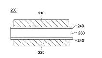
- 2A and 2B are schematic cross-sectional views illustrating an electrode assembly of a secondary battery according to an embodiment of the present invention.
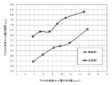
- FIG. 3 is a graph showing changes in thickness per unit content of alumina powder in Examples and Comparative Examples.
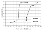
- FIG. 4 is a graph showing changes in the heating shape retention rate depending on the film thickness in Examples and Comparative Examples.
- the present invention relates to an alumina powder, an alumina slurry, an alumina-containing coating layer, a laminated separation membrane, and a secondary battery in which the ratio between the light bulk density and the heavy bulk density is within a predetermined range.
- the alumina powder of the present invention has a ratio (TBD / LBD) of light bulk density (LBD) to heavy bulk density (TBD) of 1.5 or more.
- TBD and LBD can be measured based on the standard of JIS R 9301-2-3. More specifically, TBD and LBD measuring containers use glass cylinders having an inner diameter of 37 mm, a height of 186 mm, and an internal volume of 200 mL. The powder is allowed to fall naturally from 1 cm above the top of the cylinder, and the powder is poured into the cylinder until it is full. After the powder that protrudes from the top of the graduated cylinder is scraped off with a glass rod, the powder mass in the cylinder is measured, and the mass Is divided by the cylinder volume to calculate the light bulk density (LBD).
- LBD light bulk density
- the cylinder is dropped 100 times from a height of 3 cm to perform tapping, the volume at that time is read, the mass is divided by the volume, and the bulk density (TBD) is calculated. In addition, it is measured after confirming that the volume reduction of the powder is saturated during the tapping of 100 times.
- a small difference between the TBD and LBD values may mean that there is no significant change in porosity after tapping. In this case, the TBD / LBD value decreases relatively.
- a large difference between the TBD and LBD values can mean a large reduction in porosity after tapping. In this case, the value of TBD / LBD increases relatively.
- TBD / LBD When the value of TBD / LBD is less than 1.5, the bulk density of individual secondary particles (aggregated particles) contained in the alumina powder becomes too high. In this case, the alumina aggregated particles are likely to precipitate in the alumina slurry containing the alumina powder, and it becomes difficult to ensure the dispersion stability of the alumina powder.
- TBD / LBD there is no upper limit to the value of TBD / LBD, but if the relationship between TBD and LBD becomes unbalanced, the particle shape will become more uneven and the packing property of the particles will deteriorate, so the thickness will be uniform. It may be difficult to form a thin alumina-containing coating layer.
- the lower limit of TBD / LBD of the alumina powder is 1.50, preferably 1.60, more preferably 1.65, still more preferably 1.80, more preferably 1.82.
- the upper limit of TBD / LBD of the alumina powder is not particularly defined, the upper limit is preferably 2.00, more preferably 1.90.
- the TBD / LBD value of the alumina powder may be in the range of 1.80 to 1.90, and may be in the range of 1.82 to 1.90.
- the alumina powder preferably has an LBD value of 0.39 g / cm 3 or more and 0.44 g / cm 3 or less, and the alumina powder has a TBD value of 0.72 g / cm 3 or more and 0.80 g / cm 3 or less. Preferably, it can be adjusted within the TBD / LBD range.
- the LBD value or the TBD value can be adjusted by, for example, the particle diameter, particle size distribution, processing method and the like of the alumina powder.
- particle diameter or particle size distribution of the alumina powder for example, by controlling the volume-based cumulative average particle diameter of the alumina powder, uniformity of the film thickness of the resulting alumina-containing coat layer, heat resistance, etc. Can be improved.
- the volume-based cumulative particle size controlled for the alumina particles is D50 (particle size corresponding to 50% volume-based cumulative percentage), which is a particle size corresponding to a cumulative percentage of 50% from the fine particle side determined from the particle size distribution curve, fine particles D90 (particle size corresponding to 90% volume-based cumulative percentage) corresponding to 90% cumulative percentage from the side, D10 (particle equivalent to 10% volume-based cumulative percentage) corresponding to 10% cumulative percentage from the fine particle side Diameter) and particle diameter D100 (particle diameter equivalent to 100% volume-based cumulative percentage) corresponding to a cumulative percentage of 100% from the fine particle side.
- the cumulative particle diameter is measured by a laser diffraction method using a laser particle size distribution measuring apparatus ["Microtrack MT3300EXII" manufactured by Microtrack Bell Co., Ltd.].
- the D50 value of the alumina powder is preferably 0.45 or more and 0.65 ⁇ m or less, and more preferably 0.50 or more and 0.60 ⁇ m or less.
- the D50 value is less than 0.45 ⁇ m, aggregation between particles becomes excessively dense, the porosity of the resulting alumina-containing coat layer is lowered, and there is a possibility that sufficient ion permeability cannot be secured.
- the D50 value exceeds 0.65 ⁇ m, the proportion of alumina particles having a coarse particle diameter increases, and the mechanical strength of the resulting alumina-containing coat layer is reduced due to a decrease in binding due to a decrease in the number of contact points between the particles. May decrease, or the uniformity of thickness and physical properties may decrease.
- D90 / D10 of the alumina powder of the present invention is preferably 2.0 or more and 4.0 or less, and more preferably 3.0 or more and 4.0 or less.
- the value of D90 / D10 is less than 2.0, the particle filling property is deteriorated, and the heat resistance of the laminated porous film may be lowered.
- the value of D90 / D10 exceeds 4.0, the range or deviation of the particle size distribution increases excessively, resulting in a decrease in the uniformity of the thickness of the resulting alumina-containing coat layer, or the resulting alumina-containing coat layer. The porosity may decrease excessively.
- D100 (maximum particle diameter in the particle size distribution) of the alumina powder can be adjusted by methods such as dry classification, wet classification, and sieving classification. Thereby, thickness reduction of the alumina containing coating layer obtained using the said alumina powder is realizable more effectively.
- the D100 value of the alumina powder is preferably 3.5 ⁇ m or less. If the D100 value exceeds 3.5 ⁇ m, the proportion of coarse alumina particles increases, making it difficult to reduce the thickness of the resulting alumina-containing coat layer, or the heat resistance of the resulting alumina-containing coat layer. It may decrease.
- the alumina powder may contain a minute amount of coarse particles of 20 ⁇ m or more that are not detected by a particle size distribution meter.
- the content of coarse particles having a particle diameter of 20 ⁇ m or more is preferably 100 ppm or less, more preferably 10 ppm or less, based on the total mass of the alumina powder of the present invention.
- the content of the coarse particles exceeds 100 ppm, it is difficult to reduce the thickness of the resulting alumina-containing coat layer, and voids are easily formed around the coarse particles in the resulting alumina-containing coat layer. In some cases, the heat resistance of the alumina-containing coating layer obtained may be reduced.
- alumina-containing coat layer In forming the alumina-containing coat layer, it is necessary to prepare an alumina slurry containing the alumina powder. When the content of coarse particles of D100 and 20 ⁇ m or more in the alumina powder is within the above range, alumina An additional pulverization step for further reducing the alumina particle diameter in the slurry can be omitted. Thereby, the process cost concerning manufacture of an alumina slurry can be reduced.
- the particle size distribution can be improved by adjusting the specific surface area of the alumina powder.
- the BET specific surface area of the alumina powder is preferably 3.0 m 2 / g or more and 7.0 m 2 / g or less.
- the BET specific surface area is less than 3.0 m 2 / g, the ratio of the alumina particles having a large particle diameter becomes too high, the heat resistance of the resulting alumina-containing coat layer decreases, or the thickness of the resulting alumina-containing coat layer May increase too much.
- the BET specific surface area is obtained by the nitrogen adsorption method one-point method according to the method defined in JIS-Z8830 (2013) using “HM model-1201” manufactured by Mountec.
- alumina powder By producing alumina powder within the range of the particle size, particle size distribution and specific surface area, mechanical properties such as heat resistance and durability of the alumina-containing coat layer formed using the alumina powder are improved, The uniformity of the film thickness is improved.
- the alumina-containing coat layer is applied to, for example, an electrode assembly of a secondary battery, the performance difference depending on the region is substantially eliminated, and the operation reliability at high temperature and high voltage can be improved.
- the purity of the alumina constituting the alumina powder is not particularly limited. High-purity alumina having a purity exceeding 99.9% by mass may be used, and buyer alumina having a purity of 99.9% by mass or less may be used.
- the purity of the high purity alumina is preferably 99.99% by mass or more.
- the purity of the buyer alumina is usually 90% by mass or more and preferably 99% by mass or less. From the viewpoint of cost, it is preferable to use the buyer alumina.
- the purity of alumina is calculated by subtracting the total mass (%) of Si, Na, Mg, Cu, Fe, and Ca contained in ⁇ -alumina from 100%. That is, it is calculated by the following formula.
- Purity (%) 100 ⁇ Total mass of impurities (%)
- FIG. 1 is a process flowchart for explaining a method for producing alumina powder according to an embodiment of the present invention.
- the raw material alumina powder is put into the continuous ball mill 110 and then pulverized by the ball mill.
- the raw material alumina powder may be produced by a method known in the technical field or may be a commercially available product.
- the raw material alumina powder can be produced by adding a growth agent to an aluminum precursor such as aluminum hydroxide to grow alumina crystals.
- the raw material alumina powder can also be obtained by a known method such as a Bayer method.
- the raw material alumina powder can be pulverized by a continuous ball mill 110 and separated / sorted in a classifier 120.
- an air blowing device can be connected to the continuous ball mill 110, and the pulverized raw material alumina powder can be introduced into the classifier 120 by air blowing.
- the classifier 120 includes a rotating classification wheel, and alumina particles having a particle size (D th ) or less at the classification point can pass through the classification wheel.
- alumina particles exceeding the particle size (D th ) of the classification point cannot pass through the classification wheel, are returned to the continuous ball mill 110, and can be further pulverized by the ball mill.
- the alumina particles that have passed through the classifier 120 can be moved and collected by the collector 130.
- the coarse particle size (D th ) that can pass through the classification wheel is usually adjusted to less than 5 ⁇ m, preferably less than 3 ⁇ m.
- the alumina particles collected in the collector 130 can be classified and / or collected in a plurality of batches.
- the particle property measuring unit 140 can determine whether the particle size distribution, bulk density, and specific surface area in the above range are satisfied. Batches satisfying the above range can be selected and used as the alumina powder of the present invention.
- the particle property measuring unit 140 may include a particle size distribution measuring device, a bulk density measuring device, and a BET measuring device known in the technical field.
- the alumina powder and binder resin can be mixed in a solvent, and if necessary, additional components such as a thickener and / or a surfactant can be further mixed to produce the alumina slurry.
- the additional component such as the binder resin or thickener and / or surfactant contained in the alumina slurry is insoluble in the electrolyte of the non-aqueous electrolyte secondary battery, and non-aqueous electrolysis. It is preferably electrochemically stable within the usage range of the liquid secondary battery.
- binder resin examples include polyolefins such as polyethylene, polypropylene, polybutene, and ethylene propylene copolymer; polyvinylidene fluoride (PVDF), Teflon, vinylidene fluoride-hexafluoropropylene copolymer, and tetrafluoroethylene-hexafluoropropylene.
- PVDF polyvinylidene fluoride
- Teflon Teflon
- tetrafluoroethylene-hexafluoropropylene examples include polyolefins such as polyethylene, polypropylene, polybutene, and ethylene propylene copolymer.
- Copolymer tetrafluoroethylene perfluoroalkyl vinyl ether copolymer, vinylidene fluoride-tetrafluoroethylene copolymer, vinylidene fluoride-trifluoroethylene copolymer, vinylidene fluoride-trichloroethylene copolymer, vinylidene fluoride- Fluorine-containing resin including vinyl fluoride copolymer, vinylidene fluoride-hexafluoropropylene-tetrafluoroethylene copolymer, ethylene-tetrafluoroethylene copolymer; Among fluorine-containing resins, fluorine-containing rubber having a glass transition temperature of about 23 ° C.
- aromatic polyamide aromatic polyamide (aramid resin), styrene-butadiene copolymer and its hydrogen compound, methacrylate ester copolymer, Acrylonitrile-acrylic acid ester copolymer, styrene-acrylic acid ester copolymer, rubbers such as ethylene propylene rubber and polyvinyl acetate; polyphenyl ether, polysulfone, polyether sulfone, polyphenyl sulfide, polyetherimide, polyamideimide Aromatic polymers having a melting point or glass transition temperature of about 180 ° C. or higher; polyvinyl alcohol, polyethylene glycol, cellulose ether, sodium alginate, poly Acrylic acid, polyacrylamide, water-soluble polymers such as polymethacrylic acid can be used, may be alone or in combination of two or more.
- aromatic polyamide aromatic polyamide (aramid resin), styrene-butadiene copolymer and its hydrogen compound, methacrylate ester cop
- aromatic polyamide examples include poly (paraphenylene phthalamide), poly (metaphenylene isophthalamide), poly (parabenzamide), poly (paraphenylene terephthalamide), poly (metabenzamide), and poly (4,4 ′ -Benzanilide terephthalamide), poly (paraphenylene-4,4'-biphenylenedicarboxylic acid amide), poly (metaphenylene-4,4'-biphenylenecarboxylic acid amide), poly (paraphenylene-2,6-naphthalenedicarboxylic) Acid amide), poly (metaphenylene-2,6-naphthalenedicarboxylic acid amide), poly (2-chloroparaphenylene terephthalamide), paraphenylene terephthalamide / 2,6-dichloroparaphenylene terephthalamide copolymer, metaphenylene Terephthala , And the like de / 2,6-dichloro-p-phenylene terephthalamide copo
- a fine water-insoluble polymer (emulsion) in which the water-insoluble polymer (for example, acrylate resin) is dispersed in an aqueous solvent may be used.
- the water-insoluble polymer may mean a polymer that is not dissolved in an aqueous solvent and is dispersed in an aqueous solvent as particles.
- the water-insoluble polymer may mean a polymer having an insoluble content of 90% by mass or more when 0.5 g of the polymer is mixed with 100 g of water at 25 ° C.
- the water-soluble polymer may mean a polymer having an insoluble substance of less than 0.5% by mass when 0.5 g of the polymer is mixed with 100 g of water at 25 ° C.
- the particle shape of the water-insoluble polymer is not particularly limited, but is preferably spherical.
- the water-insoluble polymer can be produced, for example, by polymerizing a composition containing a monomer described later in an aqueous solvent to form polymer particles.
- the monomer of the water-insoluble polymer may include, for example, styrene, vinyl ketone, acrylonitrile, methyl methacrylate, ethyl methacrylate, glycidyl methacrylate, glycidyl acrylate, methyl acrylate, ethyl acrylate, butyl acrylate, and the like. .
- the polymer includes a homopolymer of monomers and a copolymer of two or more monomers, and includes Teflon, a tetrafluoroethylene-hexafluoropropylene copolymer, and a tetrafluoroethylene-vinyl.
- Fluorine-containing resins such as copolymers and polyvinylidene fluoride; melamine resins; urea resins; polyethylene, polypropylene; polyacrylic acid, polymethacrylic acid, and the like.
- the fine water-insoluble polymer dispersed in the aqueous solvent includes methyl methacrylate, ethyl methacrylate, glycidyl methacrylate, glycidyl acrylate, methyl acrylate, ethyl acrylate, acrylic, from the viewpoint of binding between alumina particles.
- a homopolymer of an acrylate monomer such as butyl acid or a copolymer of two or more monomers can be preferably used.
- the binder resin is preferably a polyolefin, a fluorine-containing resin, an aromatic polyamide, a water-soluble polymer, and a fine water-insoluble polymer (emulsion) dispersed in an aqueous solvent.
- alumina-containing coating layer is disposed in contact with the positive electrode in the secondary battery, the charge / discharge rate characteristics and resistance characteristics (liquid resistance) of the non-aqueous electrolyte secondary battery due to acidic deterioration during battery operation, etc.
- Fluorine-containing resins are advantageous in that it is easy to maintain various performances of polyvinylidene fluoride resins (for example, a group consisting of vinylidene fluoride and hexafluoropyrene, tetrafluoroethylene, trifluoroethylene, trichloroethylene, and vinyl fluoride).
- a hybrid polymerized monomer with at least one monomer selected from the above and a vinylidene fluoride homopolymer) are preferred.
- the water-soluble polymer includes cellulose ether, sodium alginate and the like, and cellulose ether can be preferably used.
- Examples of the cellulose ether may include carboxymethyl cellulose (CMC), hydroxyethyl cellulose (HEC), carboxyethyl cellulose, methyl cellulose, ethyl cellulose, cyanoethyl cellulose, hydroxyethyl cellulose, and the like.
- CMC or HEC can be preferably used, and CMC can be more preferably used from the aspects such as durability, lifetime, and chemical stability.
- a usual solvent in the technical field can be used without particular limitation, and examples thereof include water, acetone, alcohols (methanol, ethanol, propyl alcohol, butanol, etc.), 1-methyl-2 - May include pyrrolidone, propylene glycol monomethyl ether acetate, tetrahydrofuran, and the like. These can be used alone or in combination of two or more.
- the aqueous solvent is not particularly limited as long as it contains water and can disperse the water-insoluble polymer particles.
- the aqueous solvent may also contain an organic solvent such as methanol, ethanol, isopropyl alcohol, acetone, tetrahydrofuran, acetonitrile, N-methylpyrrolidone that can be dissolved in an arbitrary ratio with water.
- the aqueous solvent may include a surfactant such as sodium lauryl benzene sulfonate, a dispersant such as sodium carboxymethyl cellulose polyacrylate, and the like. When using together the said solvent and additives, such as surfactant, each can be used individually or in mixture of 2 or more types.
- the mass ratio of the organic solvent to water is preferably 0.1 to 99% by mass, more preferably 0.5 to 80% by mass, and still more preferably 1 to 50% by mass.
- the solvent, binder resin, and other components that can be added to the alumina slurry described above are merely examples, and the characteristics and applications of the substrate on which the alumina slurry is applied and the alumina-containing coating layer obtained from the alumina slurry are considered. Can be selected and adjusted appropriately.
- the content of the binder resin is not particularly limited.
- the amount is preferably 0.1 to 20 parts by mass.
- the content of the solvent in the alumina slurry according to the present invention is not particularly limited, but for example, it is preferably 10 to 500 parts by mass with respect to 100 parts by mass of the alumina according to the present invention.
- the alumina slurry according to the present invention includes a dispersant, a thickener, a leveling agent, an antioxidant, an antifoaming agent, an acid, for the purpose of stabilizing the dispersion or improving the coating property.
- a dispersant such as a thickener, a leveling agent, an antioxidant, an antifoaming agent, an acid
- additives are not particularly limited as long as they are chemically stable in the range of use of the nonaqueous electrolyte secondary battery and do not greatly affect the battery reaction.
- an organic alkali salt compound such as sodium dodecyl sulfate, lithium lauryl sulfate, or sodium hexametaphosphate can be used as the dispersant.
- HEC, CMC, polyethylene glycol, etc. can be used for a thickener.
- These various additives are preferably those that can be removed when the alumina-containing coat layer is formed, but they may remain in the alumina-containing coat layer.
- content of each additive is not specifically limited, For example, it is preferable that it is 10 mass parts or less with respect to 100 mass parts of alumina which concerns on this invention.
- the alumina slurry according to the present invention can be prepared by mixing and dispersing the alumina according to the present invention, the binder resin, and the solvent.
- the dispersion method of the alumina slurry is not particularly limited, and a stirring method using a known planetary mixer or the like, or a dispersion method using ultrasonic irradiation or a bead mill can be used.
- An alumina-containing coat layer can be formed on the base material by applying the alumina slurry on the base material and performing drying and / or firing.
- the base material is not particularly limited, but can include a plastic film, a conductive film, or a carbon-based film made of polyethylene, polypropylene, polyimide, polyacryl, or the like.
- the substrate is a separation membrane for a secondary battery, it can be used as a laminated separation membrane in which an alumina-containing coating layer is formed on the separation membrane.
- alumina-containing coat layer having a thin and uniform thickness and having high heat resistance and mechanical strength.
- the secondary battery includes electrode assemblies 200 and 205 including a first electrode 210 and a second electrode 220 stacked to face each other with a separation membrane 230 therebetween.
- the secondary battery may include an electrode stack in which a plurality of electrode assemblies 200 and 205 are stacked, and a case that accommodates the electrode stack. An electrolyte can be injected into the case.
- the first electrode 210 and the second electrode 220 may correspond to a positive electrode and a negative electrode, respectively.
- the first electrode 210 and the second electrode 220 can be formed by a pressing process.
- the electrode current collector is not particularly limited, but may include a metal such as copper, aluminum, nickel, titanium, or an alloy thereof.
- the positive electrode active material is not particularly limited, but may include an oxide containing cobalt, manganese and / or nickel.
- the positive electrode active material includes lithium oxide, and a lithium-manganese oxide based material can be used.
- the negative electrode active material is not particularly limited, but is a carbon-based material such as crystalline carbon, amorphous carbon, carbon composite, carbon fiber, lithium, an alloy of lithium and another element, silicon or Tin can be included.
- the separation membrane 230 is disposed between the first electrode 210 and the second electrode 220 and physically separates them, while holding the electrolytic solution and ensuring ionic conductivity between the positive and negative electrodes.
- a first electrode tab and a second electrode tab (not shown) for connecting a power source can be coupled to the end portions of the first electrode 210 and the second electrode 220, respectively.
- the first electrode tab and the second electrode tab may be disposed on the same side of the electrode assembly 200 or on opposite sides of each other.
- the alumina-containing coating layer of the present invention can be formed on the surface of the first electrode 210, the second electrode 220, and / or the separation membrane 230. As shown in FIG. 2a, the alumina-containing coat layer 240 may be formed on both the interface of the separation membrane 230 with the first electrode 210 and the interface of the separation membrane 230 with the second electrode 220. it can. Alternatively, the alumina-containing coat layer 240 may be formed on either the interface of the separation membrane 230 with the first electrode 210 or the interface of the separation membrane 230 with the second electrode 220.
- the alumina-containing coat layer 245 can be formed on substantially the entire surface of the first electrode 210 and the second electrode 220.
- the alumina-containing coat layer can be formed by applying the alumina slurry of the present invention on the first electrode 210, the separation membrane 230 and / or the second electrode 220, and then drying or baking.
- an alumina-containing coat layer having a thin and uniform thickness can be formed.
- the separation membrane 230 When the alumina-containing coat layer is formed on the first electrode 210, the separation membrane 230, and / or the second electrode 220, a short circuit between the first electrode 210 and the second electrode 220 can be prevented.
- the separation membrane 230 is made of a resin film, the separation membrane 230 may be damaged during high temperature and high voltage operation, causing a short circuit between the electrodes.
- the alumina-containing coat layer is interposed between the separation membrane 230 and the first electrode 210 and / or the second electrode 220, the shrinkage of the separation membrane is suppressed, so that the occurrence of a short circuit can be prevented. . Since the alumina-containing coating layer is formed to have a uniform thickness in substantially the entire region, it is possible to prevent a deviation in operation due to the region of one electrode assembly or different electrode assemblies.
- the separation membrane 230 is a porous film disposed between the positive electrode and the negative electrode in the nonaqueous electrolyte secondary battery.
- the porous film only needs to be a porous and membrane-like substrate (polyolefin-based porous substrate) mainly composed of a polyolefin-based resin, and has a structure having pores connected to the inside thereof. It is a film in which gas and liquid can permeate from one side to the other side.
- the porous film melts when the battery generates heat to make the nonaqueous electrolyte secondary battery separation membrane (separator) nonporous, thereby providing a shutdown function to the nonaqueous electrolyte secondary battery separation membrane. It is given.
- the porous film may be composed of one layer or may be formed from a plurality of layers.
- the puncture strength of the porous film is preferably 3N or more. If the piercing strength is too low, the positive and negative electrode active materials may be used in the case of stacking and winding operations of the positive and negative electrodes and separation membrane in the battery assembly process, the winding group pressing operation, or when the battery is externally pressurized. The separation membrane may be pierced by the particles, and the positive and negative electrodes may be short-circuited. Further, the puncture strength of the porous film is preferably 10 N or less, and more preferably 8 N or less.
- the film thickness of the porous film may be appropriately determined in consideration of the film thickness of the nonaqueous electrolyte secondary battery member constituting the nonaqueous electrolyte secondary battery, and is preferably 4 to 40 ⁇ m. It is more preferably from 30 to 30 ⁇ m, and further preferably from 6 to 15 ⁇ m.
- the volume-based porosity of the porous film is 20 to 80% so as to increase the amount of electrolyte retained and to reliably prevent the excessive current from flowing (shut down) at a lower temperature. Preferably, it is preferably 30 to 75%.
- the average pore diameter (average pore diameter) of the porous film can provide sufficient ion permeability when used as a separation membrane, and prevent particles from entering the positive and negative electrodes. In order to be able to do, it is preferable that it is 0.3 micrometer or less, and it is more preferable that it is 0.14 micrometer or less.
- the ratio of the polyolefin component in the porous film must be 50% by volume or more of the whole porous film, preferably 90% by volume or more, and more preferably 95% by volume or more.
- the polyolefin component of the porous film preferably contains a high molecular weight component having a weight average molecular weight of 5 ⁇ 10 5 to 15 ⁇ 10 6.
- the inclusion of a polyolefin component having a weight average molecular weight of 1,000,000 or more as the polyolefin component of the porous film is preferable because the strength of the entire porous film and separation membrane for a non-aqueous electrolyte secondary battery is increased.
- the polyolefin resin contained in the porous film examples include a high molecular weight homopolymer or copolymer obtained by polymerizing ethylene, propylene, 1-butene, 4-methyl-1-pentene, 1-hexene and the like. Can do.
- the porous film may be a layer containing these polyolefin resins alone and / or a layer containing two or more of these polyolefin resins.
- high molecular weight polyethylene mainly composed of ethylene is preferable.
- a porous film does not prevent containing components other than polyolefin in the range which does not impair the function of the said layer.
- the air permeability of the porous film is usually in the range of 30 to 500 seconds / 100 cc as a Gurley value, and preferably in the range of 50 to 300 seconds / 100 cc.
- the porous film has an air permeability in the above range, sufficient ion permeability can be obtained when used as a separation membrane.
- the basis weight of the porous film is that the strength, film thickness, handling property and weight, and further, the weight energy density and volume energy density of the battery when used as a separation membrane for a non-aqueous electrolyte secondary battery can be increased.
- the method for producing a porous film when the porous film contains an ultrahigh molecular weight polyolefin and a low molecular weight hydrocarbon having a weight average molecular weight of 10,000 or less, the method for producing a porous film mainly comprising a polyolefin resin is as follows. It is preferable to manufacture.
- a step of kneading an ultrahigh molecular weight polyolefin, a low molecular weight hydrocarbon having a weight average molecular weight of 10,000 or less, and a pore-forming agent to obtain a polyolefin resin composition (2) rolling the polyolefin resin composition Step of rolling with rolls to form a sheet (rolling step), (3) Step of removing hole forming agent from the sheet obtained in step (2), (4) Sheet obtained in step (3) Can be obtained by a method comprising a step of drawing a film to obtain a porous film.
- the ultra high molecular weight polyolefin is preferably a powder.
- low molecular weight hydrocarbon examples include low molecular weight polyolefin such as polyolefin wax and low molecular weight polymethylene such as Fischer-Tropsch wax.
- the weight average molecular weight of the low molecular weight polyolefin and the low molecular weight polymethylene is preferably 200 or more and 3000 or less. When the weight average molecular weight is 200 or more, there is no risk of transpiration during the production of the porous film, and when the weight average molecular weight is 3000 or less, it is preferable because mixing with the ultrahigh molecular weight polyolefin is more uniform.
- Examples of the pore forming agent include inorganic fillers and plasticizers.
- Examples of the inorganic filler include an inorganic filler that can be dissolved in an aqueous solvent containing an acid, an aqueous solvent containing an alkali, or an aqueous solvent mainly composed of water.
- Examples of inorganic fillers that can be dissolved in an aqueous solvent containing an acid include calcium carbonate, magnesium carbonate, barium carbonate, zinc oxide, calcium oxide, aluminum hydroxide, magnesium hydroxide, calcium hydroxide, and calcium sulfate. Calcium carbonate is preferred because it is inexpensive and easily obtains a fine powder.
- Examples of the inorganic filler that can be dissolved in the aqueous solvent containing alkali include silicic acid and zinc oxide, and silicic acid is preferred because it is easy to obtain an inexpensive and fine powder.
- Examples of the inorganic filler that can be dissolved in an aqueous solvent mainly composed of water include calcium chloride, sodium chloride, and magnesium sulfate.
- liquid paraffin and low molecular weight non-volatile hydrocarbon compounds such as mineral oil can be mentioned.
- the alumina-containing coating layer is laminated on one side or both sides of the separation membrane for a non-aqueous electrolyte secondary battery, which is a porous film, as necessary.
- the method for applying the alumina slurry to the separation membrane that is, the method for forming the alumina-containing coat layer on the surface of the separation membrane that has been subjected to hydrophilic treatment as necessary is not particularly limited.
- the sequential lamination method of forming the alumina-containing coat layer on the other side, or the separation membrane It is possible to apply a simultaneous lamination method in which an alumina-containing coat layer is simultaneously formed on both sides.
- a method for forming the alumina-containing coat layer for example, a method in which an alumina slurry is directly applied to the surface of a separation membrane, and then a solvent (dispersion medium) is removed; an alumina slurry is applied to a suitable support, and a solvent (dispersion medium) ) Is removed to form an alumina-containing coat layer, and then the alumina-containing coat layer and the separation membrane are pressure-bonded, and then the support is peeled off; after the alumina slurry is applied to a suitable support, the coated surface is porous.
- the thickness of the alumina-containing coating layer is the thickness of the coating film in a wet state after coating, the weight ratio between the resin and the fine particles, and the solid content concentration of the alumina slurry (the sum of the resin concentration and the fine particle concentration). It can be controlled by adjusting etc.
- the support for example, a resin film, a metal belt, a drum, or the like can be used.
- the method of applying the alumina slurry to the separation membrane or the support is not particularly limited as long as it is a method capable of realizing a necessary basis weight and coating area.
- a conventionally well-known method can be employ
- a method specifically, for example, gravure coater method, small diameter gravure coater method, reverse roll coater method, transfer roll coater method, kiss coater method, dip coater method, knife coater method, air doctor blade coater method, blade Examples include a coater method, a rod coater method, a squeeze coater method, a cast coater method, a bar coater method, a die coater method, a screen printing method, and a spray coating method.
- the method for removing the solvent (dispersion medium) is generally a drying method.
- the drying method include natural drying, air drying, heat drying, and reduced pressure drying, and any method may be used as long as the solvent (dispersion medium) can be sufficiently removed.
- a normal drying apparatus can be used for the drying.
- the film thickness of the alumina-containing coat layer formed by the above-described method is as follows. In the case where the separation membrane is used as a base material and the alumina-containing coat layer is laminated on one side or both sides of the separation membrane, 0.5 to 15 ⁇ m (per one side) is preferable, 2 to 10 ⁇ m (per one side) is more preferable, 2 to 5 ⁇ m is further preferable, and 2 to 3 ⁇ m is particularly preferable. .
- the thickness of the alumina-containing coat layer is 1 ⁇ m or more (0.5 ⁇ m or more on one side). A short circuit can be sufficiently prevented, and the amount of electrolyte solution retained in the alumina-containing coat layer can be maintained. On the other hand, the total film thickness of the alumina-containing coat layer is 30 ⁇ m or less (15 ⁇ m or less on one side), so that lithium ions in the entire laminated separation membrane for a non-aqueous electrolyte secondary battery provided with the alumina-containing coat layer.
- the alumina-containing coat layer when the alumina-containing coat layer is laminated on both sides of the porous film, it faces the positive electrode in the porous film when a non-aqueous electrolyte secondary battery is formed. It refers at least to the physical properties of the alumina-containing coat layer laminated on the surface.
- the basis weight per unit area (per side) of the alumina-containing coat layer may be determined as appropriate in consideration of the strength, film thickness, weight, and handling properties of the non-aqueous electrolyte secondary battery laminated separation membrane. It is usually 1 to 20 g / m 2 so that the weight energy density and volume energy density of a non-aqueous electrolyte secondary battery including a laminated separation membrane for an aqueous electrolyte secondary battery as a member can be increased. preferably from ⁇ 15g / m 2, more preferably 4 ⁇ 12g / m 2.
- the weight energy density and volume of the non-aqueous electrolyte secondary battery comprising the laminated separation membrane for a non-aqueous electrolyte secondary battery provided with the alumina-containing coat layer as a member This is preferable because the energy density can be increased and the weight of the battery is reduced.
- the porosity of the alumina-containing coat layer is 20 to 90% by volume in that a laminated separation membrane for a non-aqueous electrolyte secondary battery provided with the alumina-containing coat layer can obtain sufficient ion permeability. It is preferably 30 to 70% by volume. Further, the pore diameter of the alumina-containing coat layer is 1 ⁇ m or less in terms of the fact that the laminated separation membrane for a nonaqueous electrolyte secondary battery provided with the alumina-containing coat layer can obtain sufficient ion permeability. It is preferable that it is 0.5 ⁇ m or less.
- the air permeability of the laminated separation membrane is preferably 30 to 1000 sec / 100 mL as a Gurley value, and more preferably 50 to 800 sec / 100 mL.
- the air permeability of the laminated separation membrane is preferably 30 to 1000 sec / 100 mL as a Gurley value, and more preferably 50 to 800 sec / 100 mL.
- the air permeability exceeds the above range, it means that the laminated structure of the laminated separation membrane is rough because the porosity of the laminated separation membrane is high, and as a result, the strength of the separation membrane decreases, In particular, shape stability at high temperatures may be insufficient.
- the air permeability is less than the above range, sufficient ion permeability cannot be obtained when the laminated separation membrane is used as a member for a non-aqueous electrolyte secondary battery, and non-aqueous electrolysis is not possible. The battery characteristics of the liquid secondary battery may be deteriorated.
- Example 1 and Examples shown in Table 1 below are obtained by pulverizing and classifying the raw material alumina powder produced by firing the buyer's method aluminum hydroxide in a gas furnace with the continuous ball mill described in FIG. 2 alumina powder was obtained.
- the following table shows the light-packed bulk density (LBD), heavy-packed bulk density (TBD), TBD / LBD, D50, D90, D10, D90 / D10, D100, the content of particles of 20 ⁇ m or more and the BET specific surface area of each alumina powder. It is shown in 1.
- alumina powder which only pulverized the raw material alumina powder similar to an Example with a ball mill is shown in the comparative example 1 of Table 1, and the commercially available alumina powder A is shown in the comparative example 2 of Table 1, respectively.
- LBD Light bulk density
- TBD Heavy bulk density
- TBD / LBD D50, D90, D10, D90 / D10, D100, content of particles of 20 ⁇ m or more ( ⁇ 20 ⁇ m (ppm)) and BET specific surface area
- LBD Light weight bulk density
- TBD heavy weight bulk density
- Particle size (D50, D90, D10 and D100) Measurement was performed by a laser diffraction method using a laser particle size distribution measuring apparatus ["Microtrack MT3300EXII” manufactured by Microtrack Bell Co., Ltd.]. Further, from the smaller diameter side of the particle size distribution, the cumulative percentages on the mass basis were 10%, 50%, 90%, and 100% equivalent particle diameters as D10, D50, D90, and D100, respectively. In the measurement, ultrasonic dispersion was performed for 5 minutes in a 0.2 mass% aqueous solution of sodium hexametaphosphate, and the refractive index was set to 1.76.
- HM model-1201 manufactured by Mountec Co., Ltd.
- the nitrogen adsorption method was determined by a single point method according to the method defined in JIS-Z8830 (2013).
- the drying treatment before the measurement was performed by heating at 200 ° C. for 20 minutes under a nitrogen gas flow.
- This sheet is immersed in an aqueous hydrochloric acid solution (hydrochloric acid 4 mol / L, nonionic surfactant 0.5% by mass) to remove calcium carbonate, and then stretched 6 times at 105 ° C. to form a porous substrate film.
- hydrochloric acid solution hydrochloric acid 4 mol / L, nonionic surfactant 0.5% by mass
- alumina-containing coat layer (Formation of alumina-containing coat layer) An alumina-containing coat layer was formed on the substrate porous film by the following method to produce a laminated porous film.
- Carboxymethylcellulose manufactured by Daicel Finechem Co., Ltd .; product number 1110 (3 parts by mass), isopropyl alcohol (11 parts by mass), pure water (63 parts by mass) and alumina (23 parts by mass) were mixed and stirred, followed by Kleamix (M Technique Co., Ltd.)
- the slurry was prepared by circulating and dispersing at 15000 rpm for 21 minutes using a company "CLM-0.8S"). Next, the slurry is applied on the substrate porous film with a bar coater (# 16, # 18, # 20, # 22, # 24, # 28) of each wire, and then dried at a drying temperature of 65 ° C. Then, an alumina-containing coat layer was formed on the surface of the substrate porous film to obtain a laminated porous film.
- the laminated porous film on which each alumina-containing coat layer was formed was evaluated for thinning of the alumina-containing coat layer and the heat resistance of the laminated porous film by the following methods.
- the evaluation results are summarized in Table 1 below.
- the film thickness (unit: ⁇ m) of the laminated porous film was measured with a high-precision digital measuring instrument “VL-50A” manufactured by Mitutoyo Corporation.
- the film thickness D ( ⁇ m) of the alumina-containing coat layer was calculated after subtracting the thickness of the substrate porous film from the thickness of the laminated porous film.
- the thickness of the alumina-containing coat layer formed in Comparative Example 1 was used as a reference for the laminated porous films prepared by the bar coaters (# 16, # 18, # 20, # 22, # 24, # 28) of each wire. (Ref) was used to measure the rate of change (%) in film thickness that decreased or increased compared to the reference.
- the average value (%) of the calculated change rate of the film thickness was calculated, and the degree of thinning was evaluated based on the following criteria. i) ⁇ : 20% or more decrease in film thickness compared to Ref ii) ⁇ : 10% to 19% less film thickness than Ref iii) ⁇ : Same as Ref (Comparative Example) iv) ⁇ : Thicker than Ref
- the laminated porous film of Comparative Example 1 was used as a reference (Ref) and evaluated based on the following criteria.
- % And the film thickness of the alumina-containing coat layer is 6.0 ⁇ m or more and less than 7.0 ⁇ m iii) ⁇ : Same as Ref (Comparative Example) (MD heating shape maintenance rate of laminated porous film is 80% or more and 95 % And the thickness of the alumina-containing coat layer is 7.0 ⁇ m or more) iv) x: MD heating shape maintenance rate of laminated porous film is less than 80%
- the TBD / LBD value is 1.5 or more (for example, 1.82 to 1.90), the D50 value is in the range of 0.45 to 0.65 ⁇ m, and the D90 / D10 is 4 or less.
- Example 1 and Example 2 having the values, it was found that both the film thickness reduction and the heat resistance were excellent.
- the purity of the alumina powder used in the examples was measured to be 99.9%.
- FIG. 3 using the alumina powder of Example 1 and Comparative Example 1, the film thickness of the coat layer due to the change in the amount of alumina powder per unit area is shown. From FIG. 3, it was confirmed that by using the alumina powder of Example 1, a thinner thin coating layer than that of Comparative Example 1 can be formed with the same amount.
- FIG. 4 the heating shape maintenance factor by the change of the film thickness of the coating layer formed using the alumina powder of Example 2 and Comparative Example 1 is shown. From FIG. 4, by using the alumina powder of Example 1, compared to Comparative Example 1, it was confirmed that a higher heating shape retention rate was exhibited with a thinner film thickness, and the heat resistance was improved. For example, in Comparative Example 1, when the basis weight of alumina was 10.4 g / m 2 , the thickness of the alumina-containing coat layer was 7.7 ⁇ m, and the heating shape retention rate of the laminated porous film was 87.1%.
- Example 1 when the basis weight of alumina is 10.9 g / m 2 , the thickness of the alumina-containing coat layer can be reduced to 5.3 ⁇ m, and the heating shape maintenance rate of the laminated porous film is also 95.3%. It was high.
- the present invention provides an alumina powder capable of forming a thin-film alumina-containing coat layer having a uniform thickness.
- This alumina powder can be used for an alumina-containing coat layer, a laminated separation membrane, and a secondary battery.
- first electrode 220 second electrode 230: separation membrane 240, 245: alumina-containing coat layer
Landscapes
- Chemical & Material Sciences (AREA)
- Chemical Kinetics & Catalysis (AREA)
- General Chemical & Material Sciences (AREA)
- Electrochemistry (AREA)
- Inorganic Chemistry (AREA)
- Organic Chemistry (AREA)
- Composite Materials (AREA)
- Engineering & Computer Science (AREA)
- Life Sciences & Earth Sciences (AREA)
- Geology (AREA)
- Manufacturing & Machinery (AREA)
- Thermal Sciences (AREA)
- Physics & Mathematics (AREA)
- Materials Engineering (AREA)
- Cell Separators (AREA)
- Secondary Cells (AREA)
- Battery Electrode And Active Subsutance (AREA)
- Compounds Of Alkaline-Earth Elements, Aluminum Or Rare-Earth Metals (AREA)
Abstract
Description
本発明のアルミナ粉末は、軽装嵩密度(LBD)と重装嵩密度(TBD)の比率(TBD/LBD)が1.5 以上である。
アルミナの純度は、α-アルミナ中に含まれているSi、Na、Mg、Cu、Fe、Caの質量の合計(%)を100%から差し引いて算出される。すなわち、以下の式で算出される。
純度(%)=100-不純物の質量の合計(%)
電池用途においてアルミナの純度が90質量%を下回ると、αアルミナに含まれるNa等が多くなり、良好な電気絶縁性が得られなくなったり、短絡の原因となる金属性異物の混入量が多くなったりすることがある。
前記アルミナ粉末と結合剤樹脂を溶媒に混合し、必要に応じて、増粘剤及び/又は界面活性剤などの追加の成分をさらに混合して、前記アルミナスラリーを製造することができる。
前記アルミナスラリーを基材上に塗布し、乾燥及び/又は焼成を行うことにより、基材上にアルミナ含有コート層を形成することができる。
図2a及び図2bに示すように、前記二次電池は、分離膜230を介在して対向するように積層された第1電極210及び第2電極220を含む電極組立体200,205を備える。前記二次電池は、複数の電極組立体200,205が積層された電極スタック、および該電極スタックを収容するケースを含むことができる。前記ケース内には電解液を注入することができる。
以下、本発明の理解を助けるために好適な実施例及び比較例を提示するが、これらの実施例は本発明を例示するものに過ぎず、添付の特許請求の範囲を制限するものではない。これらの実施例に対し、本発明の範疇及び技術思想の範囲内で種々の変更及び修正を加えることが可能であることは当業者にとって明らかであり、これらの変形及び修正が添付の特許請求の範囲に属することも当然のことである。
バイヤー法の水酸化アルミニウムをガス炉にて焼成して作製した原料アルミナ粉末を、図1で説明した連続ボールミル機により粉砕し、分級することで、下記の表1に示す実施例1および実施例2のアルミナ粉末を得た。各アルミナ粉末の軽装嵩密度(LBD)、重装嵩密度(TBD)、TBD/LBD、D50、D90、D10、D90/D10、D100、20μm以上の粒子の含有量及びBET比表面積を下記の表1に示す。また、実施例と同様の原料アルミナ粉末をボールミルで粉砕したのみのアルミナ粉末を表1の比較例1に、市販のアルミナ粉末Aを表1の比較例2にそれぞれ示す。
嵩密度は、JIS R 930-2-3に準拠して測定した。測定容器は、内径37mm、高さ186mm、内容積200mLのガラス製シリンダーを用いた。シリンダー上端1cm上から粉末を自然落下させ、シリンダーに満杯になるまで粉末を投入し、メスシリンダー上端からはみ出た分の粉末をガラス棒ですり落とした後、シリンダー内の粉末質量を測定し、質量をシリンダー体積で除して軽装嵩密度(LBD)を算出した。その後、シリンダーを3cmの高さから100回落下させてタッピングを行い、その時の体積を読みとり、質量を体積で除して重装嵩密度(TBD)を算出した。なお、100回のタッピングの途中で粉末の体積減少は飽和していることを確認の上で測定を行った。表1には、TBD/LBDの値も記載した。
レーザー粒度分布測定装置〔マイクロトラック・ベル(株)製「マイクロトラックMT3300EXII」〕を用いてレーザー回折法により測定した。また、粒度分布の小径側から、質量基準で累積百分率10%、50%、90%、100%相当粒子径を、それぞれD10、D50、D90、D100とした。測定に際しては、0.2質量%のヘキサメタ燐酸ソーダ水溶液で5分間超音波分散し、屈折率は1.76とした。
1000mLのビーカーに、αアルミナ粉末200gと、分散剤としてヘキサメタリン酸ソーダを0.4%含有する純水750mLとを入れ、超音波(300W)を5分間照射して分散してαアルミナスラリーを調製した後、該スラリーを20μmの篩を通過させて、篩ごと乾燥させた後、篩上に残存するαアルミナ粉末を回収した。篩上残存のαアルミナ量を、投入したαアルミナ量200gで除して、20μm以上の粗大粒子の含有量(ppmwt)とした。
比表面積測定装置として、マウンテック社製の「HM model-1201」を使用し、JIS-Z8830(2013)に規定された方法に従って、窒素吸着法一点法により求めた。ただし、測定前の乾燥処理として、窒素ガス流通下において200℃で20分間加熱して行った。
超高分子量ポリエチレン粉末(340M、三井化学株式会社製)を70質量%と、質量平均分子量1000のポリエチレンワックス(FNP-0115、日本精鑞株式会社製)30質量%と、この超高分子量ポリエチレンとポリエチレンワックスの合計100質量部に対して、酸化防止剤(Irg1010、チバ・スペシャリティ・ケミカルズ株式会社製)0.4質量部と、酸化防止剤(P168、チバ・スペシャリティ・ケミカルズ株式会社製)0.1質量部と、ステアリン酸ナトリウム1.3質量部とを加え、さらに全体積に対して38体積%となるように平均粒径0.1μmの炭酸カルシウム(丸尾カルシウム株式会社製)を加え、これらを粉末のままヘンシェルミキサーで混合した後、二軸混練機で溶融混練してポリオレフィン樹脂組成物とした。溶融押出された該ポリオレフィン樹脂組成物を表面温度が150℃の一対のロールにて圧延しシートを作製した。このシートを塩酸水溶液(塩酸4mol/L、非イオン系界面活性剤0.5質量%)に浸漬させることで炭酸カルシウムを除去し、続いて105℃で6倍に延伸して基材多孔質フィルム(厚み:16.2μm、目付量:7.3g/m2、透気度:140秒/100cc)を得た。
前記基材多孔質フィルム上に、アルミナ含有コート層を以下の方法で形成し、積層多孔質フィルムを作成した。
積層多孔質フィルムを8cm×8cmの正方形に切り出し、質量W(g)を測定し、積層多孔質フィルムの目付量(g/m2)=W/(0.08×0.08)をまず算出した。ここから基材多孔質フィルムの目付量を差し引いて、アルミナ含有コート層の目付量を算出した。
前記積層多孔質フィルムの膜厚(単位:μm)は、株式会社ミツトヨ製の高精度デジタル測定機「VL-50A」で測定した。アルミナ含有コート層の膜厚D(μm)は、積層多孔質フィルムの厚みから基材多孔質フィルムの厚みを差し引いた上で算出した。各番線のバーコーター(#16、#18、#20、#22、#24、#28)で作成した積層多孔質フィルムに対して、比較例1で形成したアルミナ含有コート層の膜厚を基準(Ref)にして、基準に比べて減少または増加した膜厚の変化割合(%)を測定した。算出した膜厚の変化割合の平均値(%)を算出し、薄膜化の度合いを、下記の基準に基づいて評価した。
i)◎:Refに比べて20%以上膜厚が減少
ii)○:Refに比べて10%~19%膜厚が減少
iii)△:Ref(比較例)と同程度(膜厚の減少が10%未満)
iv)×:Refよりも厚い
#24のバーコーターで作成した積層多孔質フィルムを8cm×8cmの正方形に切り出し、その中に6cm×6cmの正方形を書き入れたフィルムを紙に挟んで、150℃に加熱したオーブンに入れた。1時間後、オーブンからフィルムを取り出し、書き入れた四角の辺の寸法を測定し、加熱形状維持率を計算した。算出方法は以下の通りである。
MD方向の加熱前の書き入れ線長さ:L1
MD方向の加熱後の書き入れ線長さ:L2
MD加熱形状維持率(%)=(L2/L1)×100
なお、L1とL2はそれぞれ、書き入れた正方形のMD方向の左右両辺の平均値とした。ここで言うMD方向とは、基材多孔質フィルムシート成型時の長尺方向を指す。
i)◎:積層多孔質フィルムのMD加熱形状維持率が95%以上で、且つ、アルミナ含有コート層の膜厚が6.0μm未満
ii)○:積層多孔質フィルムのMD加熱形状維持率が95%以上で、且つ、アルミナ含有コート層の膜厚が6.0μm以上7.0μm未満
iii)△:Ref(比較例)と同程度(積層多孔質フィルムのMD加熱形状維持率が80%以上95%未満で、且つ、アルミナ含有コート層の膜厚が7.0μm以上)
iv)×:積層多孔質フィルムのMD加熱形状維持率が80%未満

210:第1電極
220:第2電極
230:分離膜
240,245:アルミナ含有コート層
Claims (19)
- 軽装嵩密度(LBD)と重装嵩密度(TBD)との比率(TBD/LBD)が1.5以上である、アルミナ粉末。
- アルミナ粉末の純度が99.9質量%以下である、請求項1に記載のアルミナ粉末。
- TBD/LBDが1.82~1.90である、請求項1に記載のアルミナ粉末。
- 前記LBDは、0.39~0.44g/cm3であり、前記TBDは、0.72~0.80g/cm3である、請求項1に記載のアルミナ粉末。
- 体積基準累積百分率50%相当粒子径(D50)が0.45~0.65μmである、請求項1に記載のアルミナ粉末。
- 体積基準累積百分率10%相当粒子径(D10)に対する体積基準累積百分率90%相当粒子径(D90)の比率(D90/D10)が4.0以下である、請求項5に記載のアルミナ粉末。
- 体積基準累積百分率100%相当粒子径(D100)が3.5μm以下である、請求項5に記載のアルミナ粉末。
- 20μm以上の粒子径を有する粒子の含有量が100ppm未満である、請求項1に記載のアルミナ粉末。
- BET比表面積が3.0~7.0m2/gである、請求項1に記載のアルミナ粉末。
- 請求項1~9のいずれか1項に記載のアルミナ粉末、結合剤および溶媒を含有するアルミナスラリー。
- 請求項1~9のいずれか1項に記載のアルミナ粉末および結合剤を含有するアルミナ含有コート層。
- 分離膜と、前記分離膜の少なくとも一つの表面に形成された請求項11に記載のアルミナ含有コート層とを含む積層分離膜。
- 順次積層された第1電極、分離膜及び第2電極;
前記第1電極、前記分離膜または前記第2電極の少なくとも一つの表面上に形成され、請求項1~9のいずれか1項に記載のアルミナ粉末から形成されるアルミナ含有コート層を含む二次電池。 - 前記アルミナ含有コート層は、前記第1電極及び前記分離膜の界面、または前記第2電極及び前記分離膜の界面の少なくとも一つの界面上に形成される、請求項13に記載の二次電池。
- 前記アルミナ含有コート層は、前記第1電極、前記分離膜または前記第2電極の少なくとも一つの表面を全体的に被覆する、請求項13に記載の二次電池。
- 前記アルミナ含有コート層は、前記分離膜上に形成され、前記アルミナ含有コート層は、前記アルミナ粉末及び水溶性ポリマーを含む結合剤から形成される、請求項13に記載の二次電池。
- 前記アルミナ含有コート層は、前記分離膜上に形成され、前記アルミナ含有コート層は、前記アルミナ粉末及び芳香族ポリマーを含む結合剤から形成される、請求項13に記載の二次電池。
- 前記アルミナ含有コート層は、前記分離膜上に形成され、前記アルミナ含有コート層は、前記アルミナ粉末、及びフッ素含有樹脂またはフッ素含有ゴムを含む結合剤から形成される、請求項13に記載の二次電池。
- 前記アルミナ含有コート層は、前記分離膜上に形成され、前記アルミナ含有コート層は、前記アルミナ粉末、及びアクリレート系単量体または2種以上の単量体の共重合体を含む結合剤から形成される、請求項13に記載の二次電池。
Priority Applications (5)
| Application Number | Priority Date | Filing Date | Title |
|---|---|---|---|
| EP17848809.4A EP3401281B1 (en) | 2016-09-09 | 2017-09-06 | Alumina powder, alumina slurry, alumina-containing coating layer, multilayer separation membrane and secondary battery |
| KR1020187003135A KR101909864B1 (ko) | 2016-09-09 | 2017-09-06 | 알루미나 분말, 알루미나 슬러리, 알루미나 함유 코트층, 적층 분리막 및 이차 전지 |
| CN201780010878.5A CN108602686B (zh) | 2016-09-09 | 2017-09-06 | 氧化铝粉末、氧化铝浆料、含有氧化铝的涂层、层叠分离膜和二次电池 |
| JP2018503688A JP6356937B1 (ja) | 2016-09-09 | 2017-09-06 | アルミナ粉末、アルミナスラリー、アルミナ含有コート層、積層分離膜及び二次電池 |
| US16/076,749 US10763510B2 (en) | 2016-09-09 | 2017-09-06 | Alumina powder, alumina slurry, alumina-containing coating layer, multilayer separation membrane and secondary battery |
Applications Claiming Priority (2)
| Application Number | Priority Date | Filing Date | Title |
|---|---|---|---|
| KR20160116376 | 2016-09-09 | ||
| KR10-2016-0116376 | 2016-09-09 |
Publications (1)
| Publication Number | Publication Date |
|---|---|
| WO2018047871A1 true WO2018047871A1 (ja) | 2018-03-15 |
Family
ID=61562459
Family Applications (1)
| Application Number | Title | Priority Date | Filing Date |
|---|---|---|---|
| PCT/JP2017/032150 Ceased WO2018047871A1 (ja) | 2016-09-09 | 2017-09-06 | アルミナ粉末、アルミナスラリー、アルミナ含有コート層、積層分離膜及び二次電池 |
Country Status (6)
| Country | Link |
|---|---|
| US (1) | US10763510B2 (ja) |
| EP (1) | EP3401281B1 (ja) |
| JP (1) | JP6356937B1 (ja) |
| KR (1) | KR101909864B1 (ja) |
| CN (1) | CN108602686B (ja) |
| WO (1) | WO2018047871A1 (ja) |
Cited By (7)
| Publication number | Priority date | Publication date | Assignee | Title |
|---|---|---|---|---|
| CN112189266A (zh) * | 2018-03-23 | 2021-01-05 | 美商映能量公司 | 具有改善的离子电导率的电化学电池 |
| WO2022224759A1 (ja) * | 2021-04-21 | 2022-10-27 | 住友化学株式会社 | 多孔質セラミックス焼結体の製造方法および多孔質セラミックス焼結体 |
| WO2023073842A1 (ja) | 2021-10-27 | 2023-05-04 | 日本軽金属株式会社 | 高純度微粒アルミナ粉末 |
| WO2024029464A1 (ja) * | 2022-08-04 | 2024-02-08 | 住友化学株式会社 | アルミナ粉末、樹脂組成物、およびアルミナ粉末の製造方法 |
| WO2024128317A1 (ja) * | 2022-12-16 | 2024-06-20 | デンカ株式会社 | 球状アルミナ粉末 |
| WO2024135832A1 (ja) * | 2022-12-23 | 2024-06-27 | 日鉄ケミカル&マテリアル株式会社 | 球状アルミナ粒子及びその製造方法 |
| JP2024524822A (ja) * | 2022-05-17 | 2024-07-09 | エルジー エナジー ソリューション リミテッド | リチウム2次電池用分離膜の製造方法、これから製造されたリチウム2次電池用分離膜、及びこれを備えたリチウム2次電池 |
Families Citing this family (19)
| Publication number | Priority date | Publication date | Assignee | Title |
|---|---|---|---|---|
| US10991942B2 (en) | 2018-03-23 | 2021-04-27 | EnPower, Inc. | Electrochemical cells having one or more multilayer electrodes |
| US10790505B2 (en) * | 2018-03-23 | 2020-09-29 | EnPower, Inc. | Electrochemical cells having improved ionic conductivity |
| KR102819003B1 (ko) * | 2018-06-14 | 2025-06-11 | 한양대학교 산학협력단 | 양면 코팅된 분리막 및 이를 구비하는 금속이차전지 |
| CN112655102B (zh) * | 2018-09-18 | 2025-02-21 | 松下知识产权经营株式会社 | 二次电池用浆料、二次电池用正极和二次电池 |
| US11453618B2 (en) * | 2018-11-06 | 2022-09-27 | Utility Global, Inc. | Ceramic sintering |
| KR20200065814A (ko) | 2018-11-30 | 2020-06-09 | 삼성에스디아이 주식회사 | 리튬 이차 전지용 분리막 및 이를 포함하는 리튬 이차 전지 전지 |
| WO2020138074A1 (ja) | 2018-12-26 | 2020-07-02 | 住友化学株式会社 | アルミナ、アルミナスラリー、アルミナ膜、積層セパレーター並びに非水電解液二次電池及びその製造方法 |
| CN111836780A (zh) * | 2019-02-18 | 2020-10-27 | 株式会社亚都玛科技 | 粒子材料和导热物质 |
| WO2021020887A1 (ko) | 2019-07-30 | 2021-02-04 | 주식회사 엘지화학 | 전기화학소자용 복합 분리막 및 이를 포함하는 전기화학소자 |
| EP3789135A1 (en) * | 2019-09-03 | 2021-03-10 | Siemens Energy Global GmbH & Co. KG | Powder material |
| JP7543642B2 (ja) * | 2019-11-25 | 2024-09-03 | 株式会社リコー | 液体組成物、液体吐出方法、電極の製造方法及び電気化学素子の製造方法 |
| JP2023513850A (ja) | 2019-12-11 | 2023-04-03 | ブレン-トロニクス,インコーポレイテッド | 充電式電池用の熱管理システム |
| CN112563666A (zh) * | 2020-12-18 | 2021-03-26 | 芯科众联新材料(常州)有限公司 | 一种小颗粒氧化铝粉和大颗粒氧化铝粉的混合双性剂及工艺流程 |
| AU2023209853A1 (en) * | 2022-01-19 | 2024-07-18 | Gentex Corporation | Coating and composite materials for enhancing ballistic protection |
| KR102517803B1 (ko) * | 2022-02-03 | 2023-04-05 | 주식회사 씨아이에스케미칼 | 고순도 알루미나, 이의 제조방법 및 이를 포함하는 이차전지 분리막 코팅용 슬러리 |
| KR102594964B1 (ko) * | 2022-05-26 | 2023-10-26 | 주식회사 엘지에너지솔루션 | 유기/무기 복합 다공성 코팅층을 포함하는 전기화학소자용 분리막 및 이를 포함하는 전기화학소자 |
| CN115101886B (zh) * | 2022-05-30 | 2024-09-17 | 中材锂膜(常德)有限公司 | 隔离膜涂覆材料制备方法及隔离膜 |
| KR102617244B1 (ko) * | 2022-06-15 | 2023-12-21 | 주식회사 엘지에너지솔루션 | 유기/무기 복합 다공성 코팅층을 포함하는 전기화학소자용 분리막 및 이를 포함하는 전기화학소자 |
| US12261322B2 (en) * | 2022-06-15 | 2025-03-25 | Lg Energy Solution, Ltd. | Electrochemical device separator including porous organic/inorganic composite coating layer and electrochemical device including same |
Citations (6)
| Publication number | Priority date | Publication date | Assignee | Title |
|---|---|---|---|---|
| JPH0812323A (ja) * | 1994-06-24 | 1996-01-16 | Sumitomo Chem Co Ltd | 微粒水酸化アルミニウム粉末及び微粒アルミナ粉末の製造方法 |
| JP2008137838A (ja) * | 2006-11-30 | 2008-06-19 | Tosoh Corp | アルミナ粉末及びその製造方法 |
| WO2010053157A1 (ja) * | 2008-11-06 | 2010-05-14 | トヨタ自動車株式会社 | リチウム二次電池とその利用 |
| JP2012004103A (ja) * | 2010-02-25 | 2012-01-05 | Sumitomo Chemical Co Ltd | 無機酸化物粉末および無機酸化物含有スラリーならびに該スラリーを使用したリチウムイオン二次電池およびその製造方法 |
| WO2013133331A1 (ja) * | 2012-03-06 | 2013-09-12 | 住友化学株式会社 | 水酸化アルミニウム粉末及びその製造方法 |
| WO2015111740A1 (ja) * | 2014-01-27 | 2015-07-30 | 住友化学株式会社 | リチウム二次電池用正極活物質、リチウム二次電池用正極、及びリチウム二次電池 |
Family Cites Families (9)
| Publication number | Priority date | Publication date | Assignee | Title |
|---|---|---|---|---|
| CN1202999C (zh) * | 2002-01-10 | 2005-05-25 | 新乡高技术陶瓷材料公司 | 一种制造高纯超细α—三氧化二铝微粉的方法 |
| CN1286724C (zh) | 2003-06-13 | 2006-11-29 | 昆明贵金属研究所 | 一种制备高纯超细Al2O3粉末的方法 |
| US20100221965A1 (en) * | 2008-01-29 | 2010-09-02 | Hitachi Maxell, Ltd. | Slurry for forming insulating layer, separator for electrochemical device, method for producing the same, and electrochemical device |
| JP5621248B2 (ja) | 2009-02-03 | 2014-11-12 | ソニー株式会社 | セパレータおよび電池 |
| CN103947008B (zh) * | 2011-11-15 | 2017-12-01 | 丰田自动车株式会社 | 非水电解液型二次电池 |
| JP5362132B2 (ja) | 2012-01-20 | 2013-12-11 | 住友化学株式会社 | 無機酸化物粉末および無機酸化物含有スラリーならびに該スラリーを使用したリチウムイオン二次電池およびその製造方法 |
| CN104488126B (zh) | 2012-08-01 | 2017-06-23 | 株式会社Lg 化学 | 二次电池用电极组件和包含其的锂二次电池 |
| KR20150106810A (ko) * | 2013-11-21 | 2015-09-22 | 삼성에스디아이 주식회사 | 분리막 및 이를 이용한 이차 전지 |
| EP3866244A1 (en) * | 2014-12-05 | 2021-08-18 | Celgard, LLC | Improved coated separators for lithium batteries and related methods |
-
2017
- 2017-09-06 US US16/076,749 patent/US10763510B2/en active Active
- 2017-09-06 WO PCT/JP2017/032150 patent/WO2018047871A1/ja not_active Ceased
- 2017-09-06 EP EP17848809.4A patent/EP3401281B1/en active Active
- 2017-09-06 CN CN201780010878.5A patent/CN108602686B/zh active Active
- 2017-09-06 KR KR1020187003135A patent/KR101909864B1/ko active Active
- 2017-09-06 JP JP2018503688A patent/JP6356937B1/ja active Active
Patent Citations (6)
| Publication number | Priority date | Publication date | Assignee | Title |
|---|---|---|---|---|
| JPH0812323A (ja) * | 1994-06-24 | 1996-01-16 | Sumitomo Chem Co Ltd | 微粒水酸化アルミニウム粉末及び微粒アルミナ粉末の製造方法 |
| JP2008137838A (ja) * | 2006-11-30 | 2008-06-19 | Tosoh Corp | アルミナ粉末及びその製造方法 |
| WO2010053157A1 (ja) * | 2008-11-06 | 2010-05-14 | トヨタ自動車株式会社 | リチウム二次電池とその利用 |
| JP2012004103A (ja) * | 2010-02-25 | 2012-01-05 | Sumitomo Chemical Co Ltd | 無機酸化物粉末および無機酸化物含有スラリーならびに該スラリーを使用したリチウムイオン二次電池およびその製造方法 |
| WO2013133331A1 (ja) * | 2012-03-06 | 2013-09-12 | 住友化学株式会社 | 水酸化アルミニウム粉末及びその製造方法 |
| WO2015111740A1 (ja) * | 2014-01-27 | 2015-07-30 | 住友化学株式会社 | リチウム二次電池用正極活物質、リチウム二次電池用正極、及びリチウム二次電池 |
Cited By (14)
| Publication number | Priority date | Publication date | Assignee | Title |
|---|---|---|---|---|
| CN112189266A (zh) * | 2018-03-23 | 2021-01-05 | 美商映能量公司 | 具有改善的离子电导率的电化学电池 |
| WO2022224759A1 (ja) * | 2021-04-21 | 2022-10-27 | 住友化学株式会社 | 多孔質セラミックス焼結体の製造方法および多孔質セラミックス焼結体 |
| JP2022166681A (ja) * | 2021-04-21 | 2022-11-02 | 住友化学株式会社 | 多孔質セラミックス焼結体の製造方法および多孔質セラミックス焼結体 |
| KR20240070644A (ko) | 2021-10-27 | 2024-05-21 | 니폰게이긴조쿠가부시키가이샤 | 고순도 미립 알루미나 분말 |
| JPWO2023073842A1 (ja) * | 2021-10-27 | 2023-05-04 | ||
| WO2023073842A1 (ja) | 2021-10-27 | 2023-05-04 | 日本軽金属株式会社 | 高純度微粒アルミナ粉末 |
| JP7761055B2 (ja) | 2021-10-27 | 2025-10-28 | 日本軽金属株式会社 | 高純度微粒アルミナ粉末 |
| JP2024524822A (ja) * | 2022-05-17 | 2024-07-09 | エルジー エナジー ソリューション リミテッド | リチウム2次電池用分離膜の製造方法、これから製造されたリチウム2次電池用分離膜、及びこれを備えたリチウム2次電池 |
| JP7699226B2 (ja) | 2022-05-17 | 2025-06-26 | エルジー エナジー ソリューション リミテッド | リチウム2次電池用分離膜の製造方法、これから製造されたリチウム2次電池用分離膜、及びこれを備えたリチウム2次電池 |
| WO2024029464A1 (ja) * | 2022-08-04 | 2024-02-08 | 住友化学株式会社 | アルミナ粉末、樹脂組成物、およびアルミナ粉末の製造方法 |
| WO2024128317A1 (ja) * | 2022-12-16 | 2024-06-20 | デンカ株式会社 | 球状アルミナ粉末 |
| JPWO2024128317A1 (ja) * | 2022-12-16 | 2024-06-20 | ||
| WO2024135832A1 (ja) * | 2022-12-23 | 2024-06-27 | 日鉄ケミカル&マテリアル株式会社 | 球状アルミナ粒子及びその製造方法 |
| EP4640633A4 (en) * | 2022-12-23 | 2026-04-29 | Nippon Steel Chemical & Mat Co Ltd | SPHERICAL ALUMINUM PARTICLES AND THEIR PRODUCTION METHOD |
Also Published As
| Publication number | Publication date |
|---|---|
| KR20180037617A (ko) | 2018-04-12 |
| EP3401281B1 (en) | 2020-12-23 |
| EP3401281A4 (en) | 2019-03-27 |
| JP6356937B1 (ja) | 2018-07-11 |
| CN108602686B (zh) | 2020-01-03 |
| CN108602686A (zh) | 2018-09-28 |
| KR101909864B1 (ko) | 2018-10-18 |
| JPWO2018047871A1 (ja) | 2018-09-13 |
| EP3401281A1 (en) | 2018-11-14 |
| US20190051906A1 (en) | 2019-02-14 |
| US10763510B2 (en) | 2020-09-01 |
Similar Documents
| Publication | Publication Date | Title |
|---|---|---|
| JP6356937B1 (ja) | アルミナ粉末、アルミナスラリー、アルミナ含有コート層、積層分離膜及び二次電池 | |
| JP6185133B2 (ja) | 積層多孔質フィルム及びその製造方法、積層電極シート並びに非水電解液二次電池 | |
| KR102022822B1 (ko) | 적층 다공질 필름 및 비수 전해액 이차 전지 | |
| JP6193333B2 (ja) | セパレータ及びその製造方法 | |
| KR101684224B1 (ko) | 비수전해액 이차 전지용 세퍼레이터 | |
| CN106887558B (zh) | 非水电解液二次电池用绝缘性多孔层及非水电解液二次电池用层叠间隔件 | |
| CN105579226A (zh) | 多孔层、层叠多孔层而成的间隔件、及包含多孔层或间隔件的非水电解液二次电池 | |
| CN106163791A (zh) | 层叠多孔膜及非水电解液二次电池 | |
| JP2012094493A (ja) | スラリー及び該スラリーを使用した非水電解液二次電池用セパレータの製造方法 | |
| JP6595725B2 (ja) | セパレータ、およびセパレータを含む二次電池 | |
| JP2020098721A (ja) | 多孔質層の製造方法、積層体、非水電解液二次電池用セパレータおよび非水電解液二次電池 | |
| CN113272250B (zh) | α氧化铝、浆料、多孔膜、层叠隔膜及非水电解液二次电池以及其制造方法 | |
| JP2018147884A (ja) | 非水電解液二次電池用セパレータ | |
| JP2019061972A (ja) | 非水電解液二次電池用セパレータ | |
| JP6616876B2 (ja) | 非水電解液二次電池用多孔質層 |
Legal Events
| Date | Code | Title | Description |
|---|---|---|---|
| WWE | Wipo information: entry into national phase |
Ref document number: 2018503688 Country of ref document: JP |
|
| ENP | Entry into the national phase |
Ref document number: 20187003135 Country of ref document: KR Kind code of ref document: A |
|
| WWE | Wipo information: entry into national phase |
Ref document number: 2017848809 Country of ref document: EP |
|
| ENP | Entry into the national phase |
Ref document number: 2017848809 Country of ref document: EP Effective date: 20180810 |
|
| NENP | Non-entry into the national phase |
Ref country code: DE |