WO2018047765A1 - すべり軸受 - Google Patents
すべり軸受 Download PDFInfo
- Publication number
- WO2018047765A1 WO2018047765A1 PCT/JP2017/031782 JP2017031782W WO2018047765A1 WO 2018047765 A1 WO2018047765 A1 WO 2018047765A1 JP 2017031782 W JP2017031782 W JP 2017031782W WO 2018047765 A1 WO2018047765 A1 WO 2018047765A1
- Authority
- WO
- WIPO (PCT)
- Prior art keywords
- bearing
- green compact
- dynamic pressure
- oil
- powder
- Prior art date
- Legal status (The legal status is an assumption and is not a legal conclusion. Google has not performed a legal analysis and makes no representation as to the accuracy of the status listed.)
- Ceased
Links
Images




Classifications
-
- H—ELECTRICITY
- H02—GENERATION; CONVERSION OR DISTRIBUTION OF ELECTRIC POWER
- H02K—DYNAMO-ELECTRIC MACHINES
- H02K5/00—Casings; Enclosures; Supports
- H02K5/04—Casings or enclosures characterised by the shape, form or construction thereof
- H02K5/16—Means for supporting bearings, e.g. insulating supports or means for fitting bearings in the bearing-shields
- H02K5/167—Means for supporting bearings, e.g. insulating supports or means for fitting bearings in the bearing-shields using sliding-contact or spherical cap bearings
- H02K5/1675—Means for supporting bearings, e.g. insulating supports or means for fitting bearings in the bearing-shields using sliding-contact or spherical cap bearings radially supporting the rotary shaft at only one end of the rotor
-
- B—PERFORMING OPERATIONS; TRANSPORTING
- B22—CASTING; POWDER METALLURGY
- B22F—WORKING METALLIC POWDER; MANUFACTURE OF ARTICLES FROM METALLIC POWDER; MAKING METALLIC POWDER; APPARATUS OR DEVICES SPECIALLY ADAPTED FOR METALLIC POWDER
- B22F3/00—Manufacture of workpieces or articles from metallic powder characterised by the manner of compacting or sintering; Apparatus specially adapted therefor ; Presses and furnaces
-
- B—PERFORMING OPERATIONS; TRANSPORTING
- B22—CASTING; POWDER METALLURGY
- B22F—WORKING METALLIC POWDER; MANUFACTURE OF ARTICLES FROM METALLIC POWDER; MAKING METALLIC POWDER; APPARATUS OR DEVICES SPECIALLY ADAPTED FOR METALLIC POWDER
- B22F3/00—Manufacture of workpieces or articles from metallic powder characterised by the manner of compacting or sintering; Apparatus specially adapted therefor ; Presses and furnaces
- B22F3/12—Both compacting and sintering
-
- B—PERFORMING OPERATIONS; TRANSPORTING
- B22—CASTING; POWDER METALLURGY
- B22F—WORKING METALLIC POWDER; MANUFACTURE OF ARTICLES FROM METALLIC POWDER; MAKING METALLIC POWDER; APPARATUS OR DEVICES SPECIALLY ADAPTED FOR METALLIC POWDER
- B22F5/00—Manufacture of workpieces or articles from metallic powder characterised by the special shape of the product
-
- B—PERFORMING OPERATIONS; TRANSPORTING
- B22—CASTING; POWDER METALLURGY
- B22F—WORKING METALLIC POWDER; MANUFACTURE OF ARTICLES FROM METALLIC POWDER; MAKING METALLIC POWDER; APPARATUS OR DEVICES SPECIALLY ADAPTED FOR METALLIC POWDER
- B22F5/00—Manufacture of workpieces or articles from metallic powder characterised by the special shape of the product
- B22F5/10—Manufacture of workpieces or articles from metallic powder characterised by the special shape of the product of articles with cavities or holes, not otherwise provided for in the preceding subgroups
-
- B—PERFORMING OPERATIONS; TRANSPORTING
- B22—CASTING; POWDER METALLURGY
- B22F—WORKING METALLIC POWDER; MANUFACTURE OF ARTICLES FROM METALLIC POWDER; MAKING METALLIC POWDER; APPARATUS OR DEVICES SPECIALLY ADAPTED FOR METALLIC POWDER
- B22F5/00—Manufacture of workpieces or articles from metallic powder characterised by the special shape of the product
- B22F5/10—Manufacture of workpieces or articles from metallic powder characterised by the special shape of the product of articles with cavities or holes, not otherwise provided for in the preceding subgroups
- B22F5/106—Tube or ring forms
-
- F—MECHANICAL ENGINEERING; LIGHTING; HEATING; WEAPONS; BLASTING
- F16—ENGINEERING ELEMENTS AND UNITS; GENERAL MEASURES FOR PRODUCING AND MAINTAINING EFFECTIVE FUNCTIONING OF MACHINES OR INSTALLATIONS; THERMAL INSULATION IN GENERAL
- F16C—SHAFTS; FLEXIBLE SHAFTS; ELEMENTS OR CRANKSHAFT MECHANISMS; ROTARY BODIES OTHER THAN GEARING ELEMENTS; BEARINGS
- F16C17/00—Sliding-contact bearings for exclusively rotary movement
- F16C17/02—Sliding-contact bearings for exclusively rotary movement for radial load only
-
- F—MECHANICAL ENGINEERING; LIGHTING; HEATING; WEAPONS; BLASTING
- F16—ENGINEERING ELEMENTS AND UNITS; GENERAL MEASURES FOR PRODUCING AND MAINTAINING EFFECTIVE FUNCTIONING OF MACHINES OR INSTALLATIONS; THERMAL INSULATION IN GENERAL
- F16C—SHAFTS; FLEXIBLE SHAFTS; ELEMENTS OR CRANKSHAFT MECHANISMS; ROTARY BODIES OTHER THAN GEARING ELEMENTS; BEARINGS
- F16C17/00—Sliding-contact bearings for exclusively rotary movement
- F16C17/10—Sliding-contact bearings for exclusively rotary movement for both radial and axial load
-
- F—MECHANICAL ENGINEERING; LIGHTING; HEATING; WEAPONS; BLASTING
- F16—ENGINEERING ELEMENTS AND UNITS; GENERAL MEASURES FOR PRODUCING AND MAINTAINING EFFECTIVE FUNCTIONING OF MACHINES OR INSTALLATIONS; THERMAL INSULATION IN GENERAL
- F16C—SHAFTS; FLEXIBLE SHAFTS; ELEMENTS OR CRANKSHAFT MECHANISMS; ROTARY BODIES OTHER THAN GEARING ELEMENTS; BEARINGS
- F16C17/00—Sliding-contact bearings for exclusively rotary movement
- F16C17/10—Sliding-contact bearings for exclusively rotary movement for both radial and axial load
- F16C17/102—Sliding-contact bearings for exclusively rotary movement for both radial and axial load with grooves in the bearing surface to generate hydrodynamic pressure
- F16C17/107—Sliding-contact bearings for exclusively rotary movement for both radial and axial load with grooves in the bearing surface to generate hydrodynamic pressure with at least one surface for radial load and at least one surface for axial load
-
- F—MECHANICAL ENGINEERING; LIGHTING; HEATING; WEAPONS; BLASTING
- F16—ENGINEERING ELEMENTS AND UNITS; GENERAL MEASURES FOR PRODUCING AND MAINTAINING EFFECTIVE FUNCTIONING OF MACHINES OR INSTALLATIONS; THERMAL INSULATION IN GENERAL
- F16C—SHAFTS; FLEXIBLE SHAFTS; ELEMENTS OR CRANKSHAFT MECHANISMS; ROTARY BODIES OTHER THAN GEARING ELEMENTS; BEARINGS
- F16C33/00—Parts of bearings; Special methods for making bearings or parts thereof
- F16C33/02—Parts of sliding-contact bearings
- F16C33/04—Brasses; Bushes; Linings
- F16C33/06—Sliding surface mainly made of metal
- F16C33/10—Construction relative to lubrication
- F16C33/1025—Construction relative to lubrication with liquid, e.g. oil, as lubricant
- F16C33/103—Construction relative to lubrication with liquid, e.g. oil, as lubricant retained in or near the bearing
- F16C33/104—Construction relative to lubrication with liquid, e.g. oil, as lubricant retained in or near the bearing in a porous body, e.g. oil impregnated sintered sleeve
-
- F—MECHANICAL ENGINEERING; LIGHTING; HEATING; WEAPONS; BLASTING
- F16—ENGINEERING ELEMENTS AND UNITS; GENERAL MEASURES FOR PRODUCING AND MAINTAINING EFFECTIVE FUNCTIONING OF MACHINES OR INSTALLATIONS; THERMAL INSULATION IN GENERAL
- F16C—SHAFTS; FLEXIBLE SHAFTS; ELEMENTS OR CRANKSHAFT MECHANISMS; ROTARY BODIES OTHER THAN GEARING ELEMENTS; BEARINGS
- F16C33/00—Parts of bearings; Special methods for making bearings or parts thereof
- F16C33/02—Parts of sliding-contact bearings
- F16C33/04—Brasses; Bushes; Linings
- F16C33/06—Sliding surface mainly made of metal
- F16C33/12—Structural composition; Use of special materials or surface treatments, e.g. for rust-proofing
-
- F—MECHANICAL ENGINEERING; LIGHTING; HEATING; WEAPONS; BLASTING
- F16—ENGINEERING ELEMENTS AND UNITS; GENERAL MEASURES FOR PRODUCING AND MAINTAINING EFFECTIVE FUNCTIONING OF MACHINES OR INSTALLATIONS; THERMAL INSULATION IN GENERAL
- F16C—SHAFTS; FLEXIBLE SHAFTS; ELEMENTS OR CRANKSHAFT MECHANISMS; ROTARY BODIES OTHER THAN GEARING ELEMENTS; BEARINGS
- F16C33/00—Parts of bearings; Special methods for making bearings or parts thereof
- F16C33/02—Parts of sliding-contact bearings
- F16C33/04—Brasses; Bushes; Linings
- F16C33/06—Sliding surface mainly made of metal
- F16C33/12—Structural composition; Use of special materials or surface treatments, e.g. for rust-proofing
- F16C33/128—Porous bearings, e.g. bushes of sintered alloy
-
- F—MECHANICAL ENGINEERING; LIGHTING; HEATING; WEAPONS; BLASTING
- F16—ENGINEERING ELEMENTS AND UNITS; GENERAL MEASURES FOR PRODUCING AND MAINTAINING EFFECTIVE FUNCTIONING OF MACHINES OR INSTALLATIONS; THERMAL INSULATION IN GENERAL
- F16C—SHAFTS; FLEXIBLE SHAFTS; ELEMENTS OR CRANKSHAFT MECHANISMS; ROTARY BODIES OTHER THAN GEARING ELEMENTS; BEARINGS
- F16C33/00—Parts of bearings; Special methods for making bearings or parts thereof
- F16C33/02—Parts of sliding-contact bearings
- F16C33/04—Brasses; Bushes; Linings
- F16C33/06—Sliding surface mainly made of metal
- F16C33/14—Special methods of manufacture; Running-in
- F16C33/145—Special methods of manufacture; Running-in of sintered porous bearings
-
- H—ELECTRICITY
- H02—GENERATION; CONVERSION OR DISTRIBUTION OF ELECTRIC POWER
- H02K—DYNAMO-ELECTRIC MACHINES
- H02K5/00—Casings; Enclosures; Supports
- H02K5/04—Casings or enclosures characterised by the shape, form or construction thereof
- H02K5/16—Means for supporting bearings, e.g. insulating supports or means for fitting bearings in the bearing-shields
- H02K5/167—Means for supporting bearings, e.g. insulating supports or means for fitting bearings in the bearing-shields using sliding-contact or spherical cap bearings
-
- B—PERFORMING OPERATIONS; TRANSPORTING
- B22—CASTING; POWDER METALLURGY
- B22F—WORKING METALLIC POWDER; MANUFACTURE OF ARTICLES FROM METALLIC POWDER; MAKING METALLIC POWDER; APPARATUS OR DEVICES SPECIALLY ADAPTED FOR METALLIC POWDER
- B22F2301/00—Metallic composition of the powder or its coating
- B22F2301/35—Iron
-
- B—PERFORMING OPERATIONS; TRANSPORTING
- B22—CASTING; POWDER METALLURGY
- B22F—WORKING METALLIC POWDER; MANUFACTURE OF ARTICLES FROM METALLIC POWDER; MAKING METALLIC POWDER; APPARATUS OR DEVICES SPECIALLY ADAPTED FOR METALLIC POWDER
- B22F2302/00—Metal Compound, non-Metallic compound or non-metal composition of the powder or its coating
- B22F2302/25—Oxide
-
- B—PERFORMING OPERATIONS; TRANSPORTING
- B22—CASTING; POWDER METALLURGY
- B22F—WORKING METALLIC POWDER; MANUFACTURE OF ARTICLES FROM METALLIC POWDER; MAKING METALLIC POWDER; APPARATUS OR DEVICES SPECIALLY ADAPTED FOR METALLIC POWDER
- B22F2998/00—Supplementary information concerning processes or compositions relating to powder metallurgy
- B22F2998/10—Processes characterised by the sequence of their steps
-
- B—PERFORMING OPERATIONS; TRANSPORTING
- B22—CASTING; POWDER METALLURGY
- B22F—WORKING METALLIC POWDER; MANUFACTURE OF ARTICLES FROM METALLIC POWDER; MAKING METALLIC POWDER; APPARATUS OR DEVICES SPECIALLY ADAPTED FOR METALLIC POWDER
- B22F2999/00—Aspects linked to processes or compositions used in powder metallurgy
-
- B—PERFORMING OPERATIONS; TRANSPORTING
- B22—CASTING; POWDER METALLURGY
- B22F—WORKING METALLIC POWDER; MANUFACTURE OF ARTICLES FROM METALLIC POWDER; MAKING METALLIC POWDER; APPARATUS OR DEVICES SPECIALLY ADAPTED FOR METALLIC POWDER
- B22F3/00—Manufacture of workpieces or articles from metallic powder characterised by the manner of compacting or sintering; Apparatus specially adapted therefor ; Presses and furnaces
- B22F3/24—After-treatment of workpieces or articles
- B22F3/26—Impregnating
-
- F—MECHANICAL ENGINEERING; LIGHTING; HEATING; WEAPONS; BLASTING
- F16—ENGINEERING ELEMENTS AND UNITS; GENERAL MEASURES FOR PRODUCING AND MAINTAINING EFFECTIVE FUNCTIONING OF MACHINES OR INSTALLATIONS; THERMAL INSULATION IN GENERAL
- F16C—SHAFTS; FLEXIBLE SHAFTS; ELEMENTS OR CRANKSHAFT MECHANISMS; ROTARY BODIES OTHER THAN GEARING ELEMENTS; BEARINGS
- F16C2223/00—Surface treatments; Hardening; Coating
-
- F—MECHANICAL ENGINEERING; LIGHTING; HEATING; WEAPONS; BLASTING
- F16—ENGINEERING ELEMENTS AND UNITS; GENERAL MEASURES FOR PRODUCING AND MAINTAINING EFFECTIVE FUNCTIONING OF MACHINES OR INSTALLATIONS; THERMAL INSULATION IN GENERAL
- F16C—SHAFTS; FLEXIBLE SHAFTS; ELEMENTS OR CRANKSHAFT MECHANISMS; ROTARY BODIES OTHER THAN GEARING ELEMENTS; BEARINGS
- F16C2370/00—Apparatus relating to physics, e.g. instruments
- F16C2370/12—Hard disk drives or the like
Definitions
- the present invention relates to a sliding bearing that slides through a mating material and a lubricating film to be supported.
- Sintered oil-impregnated bearings which are a kind of sliding bearings, are sometimes used for rotation support bearings of small motors such as HDD spindle motors, polygon scanner motors for laser beam printers, and fan motors for cooling fans. .
- Sintered oil-impregnated bearings have internal pores impregnated with oil (or grease; the same shall apply hereinafter), and this oil oozes out from the bearing surface to supply oil to the sliding part between the bearing surface and the shaft. Lubricity can be improved.
- the volume of the internal pores can be reduced by increasing the molding pressure of the green compact to increase the density, or molten resin or molten metal There is a method to fill the internal pores by soaking.
- the improvement in density by increasing the compacting pressure of the green compact is limited in terms of press capacity, mold strength, and productivity.
- sealing with molten resin or molten metal makes it difficult to maintain the accuracy of the bearing surface, and requires a great number of man-hours and increases costs.
- the oil film pressure can be prevented from decreasing if the bearing surface is smoothed by completely sealing the bearing surface opening or forming a plain bearing with a material that does not have pores such as molten steel.
- oil is not supplied from the internal pores, so that the oil in the sliding portion between the bearing surface and the shaft is easily depleted, and there is a possibility that seizure occurs due to contact between the bearing surface and the shaft.
- the present invention increases the load capacity by suppressing pressure loss from the bearing surface without increasing the cost, and prevents the lubricating film from being cut off at the sliding portion between the bearing surface and the counterpart material (shaft).
- the first object is to prevent burn-in.
- a hydrodynamic bearing is a fluid pressure generated in a bearing gap between a relatively rotating shaft and supports the shaft in a non-contact manner.
- a radial dynamic pressure generating portion (for example, a dynamic pressure groove) that generates dynamic pressure in a lubricating fluid such as oil (or grease, the same applies hereinafter) filled in the bearing gap is formed on the inner peripheral surface of the dynamic pressure bearing.
- Patent Document 2 discloses a method in which a dynamic pressure groove is formed on the inner peripheral surface of a cylindrical sintered body by sizing after sintering. Specifically, a core rod having a mold corresponding to the shape of the dynamic pressure groove is inserted into the inner periphery of a cylindrical sintered body, and the sintered body and the core rod are press-fitted into the die in this state. Are pressed against a core rod mold to form a dynamic pressure groove. After that, the sintered body and the core rod are raised and discharged from the die, so that the pressing force by the die is released, the diameter of the sintered body is expanded by the spring back, and the inner peripheral surface of the sintered body is released from the core rod.
- the hydrodynamic bearing is formed of sintered metal as described above, the metal powder is compression-molded to form a green compact, and then the green compact is heated to a high temperature (800 to 1300 ° C for iron-based materials).
- a high temperature 800 to 1300 ° C for iron-based materials.
- the dimensional accuracy is greatly lost. For this reason, it is necessary to subject the sintered body to the above sizing for the purpose of dimensional correction and formation of dynamic pressure grooves, resulting in high costs.
- an oxide film is formed on the surface of the metal powder particles constituting the green compact by heating the green compact in which the dynamic pressure grooves are molded in a water vapor atmosphere.
- the strength is improved by bonding the particles with a material coating.
- the green compact thus treated (hereinafter also referred to as “oxidized green compact”) is inferior in strength to the sintered body, but the particles are bonded with an oxide film. , Have some strength. Since the heating temperature during this oxidation treatment is much lower than the conventional sintering temperature (for example, about 350 to 600 ° C.), the dimensional change of the oxidized green compact and the dynamic pressure groove can be suppressed, and sizing is not performed. Also, the required dimensional accuracy can be satisfied.
- the surface of the oxidized green compact is roughened by subjecting the green compact having the dynamic pressure grooves to the water vapor treatment as described in Patent Document 3 above.
- the oxide film formed on the surface of the green compact becomes thick because the oxide film is formed at a high rate.
- Surface roughness and waviness (particularly roughness) increase.
- the bearing surface of the hydrodynamic bearing faces the mating material (shaft) through a very small bearing clearance, so if the bearing surface becomes too rough or wavy, it will easily come into contact with the mating material and may cause abnormal noise. There is.
- the bearing surface and shaft slide because the pressure of the lubricating film in the bearing gap is low. If the bearing surface is too rough or wavy, the bearing surface Promotes surface and mating wear.
- the present invention provides a hydrodynamic bearing formed by subjecting a green compact having a hydrodynamic groove to an oxidation treatment to improve the surface accuracy of the bearing surface and suppress the generation of abnormal noise and the wear of the bearing surface and the counterpart material. This is the second purpose.
- Patent Document 3 a green compact is formed from a raw material powder obtained by mixing copper powder and iron powder.
- a green compact containing a plurality of types of metal powder is subjected to an oxidation treatment, a difference occurs in the formation state of the oxide film depending on the type of metal. It was revealed that the thickness of the oxide film to be formed and the adhesion between the oxide film and the particles became non-uniform, and as a result, the dimensional accuracy of the oxidized green compact deteriorated.
- a third object of the present invention is to improve the dimensional accuracy of a hydrodynamic bearing made of oxidized green compact.
- the fluid dynamic pressure bearing device supports the shaft in a non-contact manner so as to be relatively rotatable by the pressure of the oil film formed in the bearing gap between the shaft and the bearing member in association with the relative rotation.
- the fluid dynamic pressure bearing device is widely used as a small, high-speed, high-precision bearing device such as an HDD, a polygon mirror motor, and a small cooling fan motor.
- Fluid dynamic pressure bearing devices are roughly classified into a full-fill structure in which oil (or grease, hereinafter the same) is completely filled and a partial fill structure in which an air layer is present.
- Full-fill type fluid dynamic bearing device is less likely to cause oil leakage because the oil level position is less likely to fluctuate compared to partial fill fluid dynamic bearing device, but seals are provided to prevent oil leakage reliably. It is common to provide a structure.
- a wedge-shaped seal space (so-called taper seal) is formed between an inner peripheral surface of a seal member provided in an opening of a housing and a tapered surface provided on an outer peripheral surface of a shaft member. is doing.
- the oil surface is maintained in the seal space by a capillary action, and the oil volume is prevented from flowing out by buffering the increase in the oil volume accompanying the temperature rise in the seal space.
- the seal space as described above needs a volume capable of absorbing the volume change of the oil accompanying the temperature change, the larger the amount of oil filled in the fluid dynamic bearing device, the smaller the volume of the seal space. There is a need to increase it.
- oil is also impregnated in the internal pores of the bearing member. This leads to further expansion of the volume of the space.
- the total length (axial length) of the fluid dynamic pressure bearing device is naturally limited.
- the shaft of the seal space is used to secure the volume of the seal space. If the directional dimension is increased, the axial length (bearing span) of the radial bearing gap cannot be sufficiently secured, and the load capacity and rigidity of the bearing may be reduced.
- the internal pores of the bearing member made of sintered metal are reduced, the amount of oil impregnated in the bearing member, and hence the total amount of oil filled in the fluid dynamic bearing device, is reduced.
- the volume of the space can be reduced, and the axial length of the seal space can be shortened.
- a fourth object is to improve the load capacity and the bearing rigidity by reducing the axial dimension of the fluid dynamic bearing device or expanding the bearing span.
- the first invention of the present application made to achieve the first object comprises an oxidized green compact in which the particles are bonded together by an oxide film formed on the surface of the metal powder particles, and is a counterpart to be supported.
- the bearing surface In a plain bearing having a bearing surface that slides through a material and a lubricating film, the bearing surface has a large number of openings that are blocked from communicating with internal pores by the oxide film.
- the slide bearing of the present invention does not sinter the green compact at a high temperature (for example, 850 ° C.) like a general sintered bearing, but heat-treats the green compact at a relatively low temperature (for example, 500 ° C.). In this way, an oxide film is formed on the surface of the metal powder particles constituting the green compact, and the particles are bonded together by this oxide film. In this case, since at least a part of the internal pores of the oxidized green compact is filled with the oxide coating, it becomes difficult for oil to escape from the surface of the oxidized green compact, so there is no need for a separate sealing treatment. The pressure capacity from the bearing surface can be suppressed and the load capacity can be increased.
- a high temperature for example, 850 ° C.
- a relatively low temperature for example, 500 ° C.
- the oxide coating does not completely seal the opening of the surface of the oxidized green compact so that the bearing surface becomes smooth. A large number of openings remain that are blocked from communicating with each other.
- This opening functions as an oil reservoir that holds oil, and the oil held in the opening is supplied to the sliding portion between the bearing surface and the counterpart material, thereby preventing the oil film from being cut off at the sliding portion.
- the “internal pores” mean pores formed by particles not exposed on the surface of the oxidized green compact or an oxide film formed on the surface thereof.
- the above-mentioned plain bearing preferably has an oil content of 4 vol% or less and a surface opening ratio of the bearing surface of 40% or more.
- the surface opening ratio is an area ratio of all openings on the bearing surface including not only the opening not communicating with the internal pore as described above but also the opening communicating with the internal pore.
- the sliding bearing preferably has an oil permeability of 0.01 g / 10 min or less.
- the oil permeability is determined by contacting the oil with the surface of the slide bearing (for example, the inner peripheral surface) and holding the oil under a predetermined pressure (0.4 MPa in this case) for 10 minutes. It is obtained by measuring the total weight of oil that has oozed from the opening on the opposite surface (for example, the outer peripheral surface).
- the bearing surface can be, for example, a smooth cylindrical surface that does not have a dynamic pressure groove or the like.
- the slide bearing is configured to be a fluid dynamic pressure bearing by facing the outer peripheral surface of the shaft member in which the dynamic pressure groove is formed, or to be a circular bearing by facing the cylindrical outer peripheral surface of the shaft member. be able to.
- a dynamic pressure groove may be formed on the bearing surface.
- the sliding bearing can be configured to face a smooth outer peripheral surface or end surface of the shaft member to constitute a fluid dynamic pressure bearing.
- the above slide bearing can be incorporated into a fluid dynamic bearing device, for example. Specifically, it comprises the above-mentioned slide bearing and a shaft member as the mating member inserted in the inner periphery of the slide bearing, and a radial between the bearing surface of the slide bearing and the outer peripheral surface of the shaft member It is possible to obtain a fluid dynamic bearing device that supports the shaft member in a non-contact manner so as to be relatively rotatable with the pressure of the lubricating film in the bearing gap.
- the second invention of the present application made to achieve the second object is a step of compressing metal powder to form a green compact, and simultaneously forming a dynamic pressure groove on the inner peripheral surface of the green compact; A step of heating the green compact in an air atmosphere to form an oxide film on the surface of the metal powder particles constituting the green compact, and bonding the particles together by the oxide film.
- a method for manufacturing a pressure bearing is provided.
- an oxide film is mildly formed on the surface of the green compact, so that the surface roughness and undulation of the oxidized green compact can be suppressed.
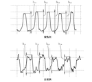
- 14 (A) and 14 (B) show the profile in the circumferential direction of the inner peripheral surface of the oxidized green compact converted into a straight line, with the upper side representing the groove and the lower side representing the hill. ing.
- the depth of the dynamic pressure groove needs to be smaller than the springback amount of the sintered body at the time of mold release. There is.
- the springback amount of the sintered body is small, the depth of the dynamic pressure groove is limited.
- the depth of the dynamic pressure groove is about 3 ⁇ m.
- the size of the bearing gap between the inner peripheral surface of the dynamic pressure bearing and the outer peripheral surface of the shaft is generally set to be equal to or less than the depth of the dynamic pressure groove in order to ensure fluid pressure.
- the bearing gap is usually set to 3 ⁇ m or less. Since the bearing gap is small as described above, the hydrodynamic bearing and the shaft are easily brought into contact with each other when the shaft is swung.
- the dynamic pressure grooves are formed simultaneously with the formation of the green compact. Since the amount of spring back when the green compact is released (the amount of expansion of the inner peripheral surface) is larger than the amount of spring back when the sintered body is released, the dynamic pressure grooves are formed in the green compact as described above.
- the depth of the dynamic pressure groove can be increased as compared with the case where the dynamic pressure groove is molded in the sintered body.
- the ratio h / d between the depth h ( ⁇ m) of the dynamic pressure groove and the inner diameter d (mm) of the green compact can be made larger than 2.
- the heating temperature at the time of the oxidation treatment of the green compact is sufficiently lower than the conventional sintering temperature (for example, 600 ° C. or less). Thereby, since the dimensional change of the green compact is suppressed, sizing after heating can be omitted.
- the particles are formed of an oxidized green powder in which the particles are bonded to each other by an oxide film formed on the surface of the metal powder particles in an air atmosphere, and a dynamic pressure groove is formed on the inner peripheral surface.
- the obtained hydrodynamic bearing can be obtained.
- the green compact is composed of a plurality of types of metal powders, the thickness of the oxide film formed on the surface of the particles and the adhesion to the base material are different, so that the dimensional accuracy and bearing characteristics may not be satisfied. Therefore, in the above dynamic pressure bearing, it is preferable that 95 wt% or more of the green compact is a single kind of metal (for example, iron).
- the oxide film is made of Fe 3 O 4 , Fe 2 O 3 , FeO or the like.
- the oxide film becomes a single phase of only Fe 3 O 4 .
- the oxide film becomes a mixed phase of Fe 3 O 4 and Fe 2 O 3 . Therefore, in an oxide green compact mainly composed of iron, if the oxide film is a mixed phase of Fe 3 O 4 and Fe 2 O 3 , it can be assumed that the oxide film is formed by heating in an air atmosphere. it can.
- the above-mentioned dynamic pressure bearing can be used, for example, by impregnating oil in the internal pores of the oxidized green compact.
- the above hydrodynamic bearing can be incorporated into a fluid dynamic bearing device.
- a radial bearing provided with the above-mentioned dynamic pressure bearing and a shaft member inserted into the inner periphery of the dynamic pressure bearing, and between the inner peripheral surface of the dynamic pressure bearing and the outer peripheral surface of the shaft member It is possible to obtain a fluid dynamic bearing device that supports the shaft member in a non-contact manner so as to be relatively rotatable by a dynamic pressure action of an oil film generated in the gap.
- the third invention of the present application made to achieve the third object has a radial dynamic pressure generating portion on the inner peripheral surface, and the particles are connected to each other through an oxide film formed on the surface of the metal powder particles.
- 99 wt% or more of the metal powder contained in the oxidized green compact is composed of a single kind of metal powder.
- the third invention of the present application compresses a raw material powder in which a single kind of metal powder occupies 95 wt% or more to form a green compact, and simultaneously forms a radial dynamic pressure generating portion on the inner peripheral surface of the green compact. And heating the green compact to form an oxide film on the surface of the metal powder particles constituting the green compact, and the particles are bonded to each other through the oxide film to form an oxide green compact. Obtaining a body.
- the metal powder contained in the oxidized green compact is constituted by a single kind of metal powder, or 95 wt% or more of the raw powder of the green compact is constituted by a single kind of metal powder. Consists of.
- the green compact is formed of substantially a single type of metal powder, an oxide film can be uniformly formed on the particle surface of the metal powder.
- the dimensional change of the green compact due to the heat treatment is suppressed, and the dimensional accuracy of the dynamic pressure bearing (oxidized green compact), especially the dimensional accuracy of the inner peripheral surface and the radial dynamic pressure generating part (for example, dynamic pressure groove) Enhanced.
- the “single type metal powder” referred to in the present invention is, for example, a prealloy powder component (composition) in which each particle has a plurality of types of metal components in addition to a powder made of a single metal such as iron powder or copper powder. ) Are the same.
- iron powder may be used as the single type of metal powder that constitutes the green compact. preferable.
- the types of metal powder include reduced powder, electrolytic powder, and atomized powder.
- Electrolytic powder has a dendritic shape, so the particles have many entanglements and it is easy to obtain the strength required for a hydrodynamic bearing, but it is difficult to uniformly form an oxide film on the dendritic particle surface.
- the atomized powder has substantially spherical particles, an oxide film is easily formed uniformly on the particle surface, but there is little entanglement between the particles and it is difficult to obtain the strength required for a hydrodynamic bearing.
- the reduced powder has voids inside the particles, the particles are easily entangled by compression molding, and the strength is easily increased. Further, since the shape of the particles of the reduced powder is relatively close to a sphere, an oxide film is easily formed uniformly on the particle surface. From the above, it is preferable to use reduced powder as the single type of metal powder constituting the green compact.
- a fluid dynamic pressure bearing device including a radial bearing portion that supports a member in a relatively rotatable manner has high load capacity and high bearing rigidity due to high dimensional accuracy of the dynamic pressure bearing.
- a motor including the fluid dynamic pressure bearing device described above, a rotor magnet provided on a rotating side of the housing and the shaft member, and a stator coil provided on a fixed side of the housing and the shaft member. Has high rotational accuracy.
- an oxide film is mildly formed on the surface of the green compact as compared with the case of heating in a water vapor atmosphere. Swelling is suppressed.
- the oxide film is formed of, for example, Fe 3 O 4 or Fe 2 O 3 , or a mixture thereof.
- the fourth invention of the present application made to achieve the fourth object includes a shaft member, a porous oil-impregnated bearing in which the shaft member is inserted on the inner periphery, and a holder for holding the porous oil-impregnated bearing on the inner periphery.
- a radial bearing portion that supports the shaft member in a relatively rotatable manner, and an oil and air filled between the inner peripheral surface of the seal portion and the outer peripheral surface of the shaft member and filled in the housing.
- the porous oil-impregnated bearing is an oxidized green compact in which the particles are bonded to each other through an oxide film formed on the surface of the metal powder particles. And the oil content of the porous oil-impregnated bearing is 4 And equal to or less than ol%.
- the porous oil-impregnated bearing of the fluid dynamic pressure bearing device does not sinter the green compact at a high temperature (for example, 850 ° C.) unlike a general sintered bearing, but relatively low temperature in the green compact.
- a high temperature for example, 850 ° C.
- an oxide film is formed on the surface of the metal powder particles constituting the green compact, and the particles are bonded to each other by the oxide film.
- at least a part of the internal pores of the oxidized green compact is filled with the oxide coating and the internal pores of the oxidized green compact are reduced, so that the oil content of the porous oil-impregnated bearing may be 4 vol% or less. it can.
- the amount of oil impregnated in the porous oil-impregnated bearing is reduced, so that the total amount of oil filled in the fluid dynamic bearing device is reduced.
- the volume of the seal space for buffering the volume change of the oil particularly the axial dimension of the seal space, can be reduced, so the load due to the reduction of the axial dimension of the fluid dynamic bearing device or the expansion of the bearing span.
- the capacity and bearing rigidity can be improved.
- the metal powder contained in the porous oil-impregnated bearing is substantially composed of only one kind of metal powder.
- 99 wt% or more of the metal powder contained in the oxidized green powder constituting the porous oil-impregnated bearing is composed of a single type of metal powder.
- iron powder it is preferable to use iron powder as the single type of metal powder.
- a motor including the fluid dynamic pressure bearing device described above, a rotor magnet provided on a rotating side of the housing and the shaft member, and a stator coil provided on a fixed side of the housing and the shaft member. Can reduce the size in the axial direction or improve the rotation accuracy.
- the porous oil-impregnated bearing includes a step of compressing metal powder to form a green compact, and heating the green compact to form an oxide film on the surface of the metal powder particles constituting the green compact. Forming an oxidized green compact by bonding the particles with each other through the oxide film, and impregnating the internal pores of the oxidized green compact with oil, and a porous oil impregnation having an oil content of 4 vol% or less It can be manufactured through a process of obtaining a bearing.
- an oxide film is mildly formed on the surface of the green compact as compared with the case of heating in a water vapor atmosphere. Swelling is suppressed.
- the oxide film is formed of, for example, Fe 3 O 4 or Fe 2 O 3 , or a mixture thereof.
- the first invention of the present application at least a part of the internal pores of the sliding bearing (green compact) is filled with the oxide coating, thereby suppressing pressure loss from the bearing surface and increasing the load capacity. it can.
- a large number of openings serving as oil reservoirs are provided on the bearing surface of the slide bearing, it is possible to prevent the oil film from being cut off at the sliding portion with the counterpart material and to prevent seizure.
- the surface accuracy of the bearing surface can be increased.
- wear of the mating material can be suppressed.
- the dimensional accuracy of the hydrodynamic bearing made of oxidized green compact can be increased.
- the total amount of oil filled in the fluid dynamic pressure bearing device is reduced by reducing the internal pores of the oxidized green compact by the oxide coating and suppressing the oil content of the porous oil-impregnated bearing. Since it can be reduced, the axial dimension of the seal space can be reduced. Thereby, the load capacity and bearing rigidity can be improved by reducing the axial dimension of the fluid dynamic bearing device or by increasing the bearing span.
- the left figure shows the cross-sectional structure of the green compact before heat treatment
- the middle figure shows the cross-sectional structure of the green compact after degreasing
- the right figure shows the cross-sectional structure of the green compact after oxidation (oxidized green compact).
- It is a graph showing the relationship between the true density ratio of an oxidation green compact, and oil content.
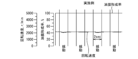
- It is a graph showing the rotational speed and oil film formation rate of the motor which has the slide bearing which concerns on an Example.
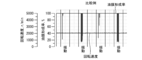
- It is a graph showing the rotational speed and oil film formation rate of a motor which has a slide bearing concerning a comparative example.
- the upper row shows the profile of the inner peripheral surface of the oxidized green compact (Example) that has been oxidized in an air atmosphere
- the lower row shows an oxidized green compact that has been oxidized in a steam atmosphere (comparative). It is the profile of the circumferential direction of the internal peripheral surface of an example).
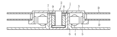
- the spindle motor shown in FIG. 1 is used in a disk drive device such as an HDD, and includes a fluid dynamic bearing device 1 that rotatably supports a shaft member 2 in a non-contact manner, and a disk hub 3 mounted on the shaft member 2. And, for example, a stator coil 4 and a rotor magnet 5 that are opposed to each other via a gap in the radial direction.
- the stator coil 4 is attached to the casing 6, and the rotor magnet 5 is attached to the disk hub 3.
- the housing 7 of the fluid dynamic bearing device 1 is mounted on the inner periphery of the casing 6.
- the disk hub 3 holds a predetermined number of disks D such as magnetic disks.
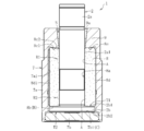
- the fluid dynamic bearing device 1 includes a bearing sleeve 8 as a slide bearing (dynamic pressure bearing) according to an embodiment of the present invention, and a shaft member as a counterpart material supported by the bearing sleeve 8. 2, a bottomed cylindrical housing 7 that holds the bearing sleeve 8 on the inner periphery, and a seal portion 9 provided at an opening at one axial end of the housing 7.
- the housing 7 and the seal part 9 are comprised by one component.
- the closed side of the housing 7 is referred to as the lower side and the open side of the housing 7 is referred to as the upper side in the axial direction, but this is not intended to limit the usage mode of the fluid dynamic bearing device 1.
- the shaft member 2 includes a shaft portion 2a and a flange portion 2b provided at the lower end of the shaft portion 2a.
- the shaft member 2 is formed of, for example, metal, and in this embodiment, the entire shaft member 2 including the shaft portion 2a and the flange portion 2b is integrally formed of stainless steel.
- the bearing sleeve 8 has a cylindrical shape, and a radial bearing surface facing the outer peripheral surface 2a1 of the shaft member 2 is provided on the inner peripheral surface 8a.
- radial bearing surfaces A are formed at two locations spaced in the axial direction of the inner peripheral surface 8 a of the bearing sleeve 8.
- the inner diameter of the radial bearing surface A is set to ⁇ 3 to 5 mm.
- dynamic pressure grooves are formed, and in this embodiment, as shown in FIG. 3, dynamic pressure grooves G1, G2 arranged in a herringbone shape are provided in each radial bearing surface A.
- a region indicated by cross-hatching in the figure indicates a hill raised on the inner diameter side (the same applies to FIG. 4).
- the upper dynamic pressure groove G1 has an asymmetric shape in the axial direction
- the lower dynamic pressure groove G2 has a symmetrical shape in the axial direction.
- the oil in the radial bearing gap is pushed in the axial direction by the upper dynamic pressure groove G ⁇ b> 1 having the axially asymmetric shape, and the oil is forcibly circulated inside the housing 7.
- a cylindrical surface that is continuous with the bottom surfaces of the dynamic pressure grooves G1 and G2 is provided in a region between the axial directions of the radial bearing surface A.
- both the upper and lower dynamic pressure grooves G1, G2 may have an axially symmetrical shape.
- the upper and lower dynamic pressure grooves G1 and G2 may be continuous in the axial direction, or one or both of the upper and lower dynamic pressure grooves G1 and G2 may be omitted. Further, a spiral dynamic pressure groove or a dynamic pressure groove extending in the axial direction may be formed on the radial bearing surface. Further, the inner circumferential surface 8a (radial bearing surface A) of the bearing sleeve 8 may be a cylindrical surface, and a dynamic pressure groove may be formed on the outer circumferential surface 2a1 of the shaft member 2.
- a thrust bearing surface B facing the upper end surface 2b1 of the flange portion 2b of the shaft member 2 is provided on the lower end surface 8b of the bearing sleeve 8.
- a pump-in type spiral-shaped dynamic pressure groove G3 as shown in FIG. 4 is formed on the thrust bearing surface B.
- a shape of the dynamic pressure groove a herringbone shape, a radiation groove shape, or the like may be adopted.
- a dynamic pressure groove may be formed on the upper end surface 2b1 of the flange portion 2b of the shaft member 2 with the lower end surface 8b (thrust bearing surface B) of the bearing sleeve 8 as a flat surface.
- annular groove 8c1 and a plurality of radial grooves 8c2 provided on the inner diameter side of the annular groove 8c1 are formed on the upper end surface 8c of the bearing sleeve 8.
- a plurality of axial grooves 8d1 are provided on the outer peripheral surface 8d of the bearing sleeve 8 at equal intervals in the circumferential direction.
- the space on the outer diameter side of the flange portion 2b of the shaft member 2 communicates with the seal space S through the axial groove 8d1, the annular groove 8c1, the radial groove 8c2, and the like. Occurrence is prevented.
- the annular groove 8c1 and the radial groove 8c2 may be omitted, and the upper end surface 8c of the bearing sleeve 8 may be a flat surface.
- the surface of the bearing sleeve 8 is a die-molded surface including the bottom surfaces of the dynamic pressure grooves G1, G2, and G3 and the top and side surfaces of the hills.
- the bearing sleeve 8 is not sized, and no sliding mark is formed on the surface of the bearing sleeve 8.
- the bearing sleeve 8 impregnated oil into the internal pores of an oxidized green compact, that is, a green compact (oxidized green compact) in which metal powder particles are bonded together through an oxide film. It is a porous oil-impregnated bearing.
- the bearing sleeve 8 of this embodiment is composed of, for example, an oxidized green compact that contains 95 wt% or more of a single type of metal and is substantially made of a single type of metal powder. Specifically, 99 wt% or more of the metal powder constituting the oxidized green compact is composed of a single type of metal powder (including an oxide film on the particle surface).
- the bearing sleeve 8 is composed of an oxidized green powder made of only iron powder (particularly reduced iron powder) as metal powder. Specifically, as shown in FIG. 5, the bearing sleeve 8 is composed of an oxidized green compact composed of iron particles 11 and an oxide film 12 formed on the surface of the iron particles 11. The iron particles 11 are bonded to each other by an oxide coating 12. Specifically, the oxide coating 12 formed on the surface of each iron particle 11 spreads between the iron particles 11 to form a network, thereby ensuring the strength of the bearing sleeve 8.
- the oil content of the bearing sleeve 8 is, for example, 4 vol% or less, preferably 2 vol% or less. Further, the oil permeability of the bearing sleeve 8 is set to 0.01 g / 10 min or less, for example.
- the oil content of the bearing sleeve 8 is measured by the open porosity measuring method described in JIS Z 2501: 2000.
- the surface of the bearing sleeve 8 is not completely sealed and smoothed by the oxide coating 12, and the surface of the bearing sleeve 8, particularly the radial bearing surface A and the thrust bearing surface B, has a large number of openings. 13a (a minute recess) is formed.
- the many openings 13a communicate with the internal pores 13b (the pores 13b formed by the iron particles 11 not exposed on the surface of the bearing sleeve 8 or the oxide coating 12 formed on the surface thereof). 12 is blocked. That is, before the oxide film 12 is formed, the internal pores 13b and the opening 13a are communicated with each other. However, when the oxide film 12 is divided, any surface (for example, the inner peripheral surface 8a) is formed. ) Is formed in the opening 13a only.
- the inner side of the opening 13 a is closed with the oxide film 12.
- the numerous openings 13a function as an oil reservoir that holds oil.
- Each bearing surface A, B of the bearing sleeve 8 is also provided with an opening 13c communicating with the internal pore 13b. At least a part of the opening 13c is in communication with the other surface (for example, the outer peripheral surface 8d) of the bearing sleeve 8.
- the surface opening ratios of the radial bearing surface A and the thrust bearing surface B of the bearing sleeve 8 are each 40% or more.
- the surface aperture ratios of the bearing surfaces A and B are measured by analyzing captured images of the bearing surfaces A and B.
- FIG. 6 is an enlarged photograph of the inner peripheral surface 8a (radial bearing surface A) of the bearing sleeve 8, and the region shown in black is the opening 13a or 13c. By calculating the ratio of black areas (openings 13a and 13c) in this image, the surface aperture ratio is obtained.
- the straight line shown by FIG. 6 is a boundary of a dynamic pressure groove and a hill part.
- the housing 7 includes a cylindrical side portion 7a and a bottom portion 7b that closes an opening at the lower end of the side portion 7a (see FIG. 2).
- the side part 7a and the bottom part 7b are formed separately.
- the side part 7a is formed in a cylindrical shape with resin or metal.
- the outer peripheral surface 8d of the bearing sleeve 8 is fixed to the inner peripheral surface 7a1 of the side portion 7a by an appropriate means such as adhesion or press fitting.
- the bottom portion 7b is formed in a disk shape with, for example, resin or metal, and is fixed to the lower end portion of the side portion 7a by appropriate means such as press-fitting and adhesion.
- a thrust bearing surface C is formed on the upper end surface 7b1 of the bottom 7b.
- a pump-in type spiral-shaped dynamic pressure groove is formed on the thrust bearing surface C as a thrust dynamic pressure generating portion (not shown).
- a shape of the dynamic pressure groove a herringbone shape, a radiation groove shape, or the like may be adopted.
- the dynamic pressure groove may be formed in the lower end surface 2b2 of the flange portion 2b of the shaft member 2 with the upper end surface 7b1 (thrust bearing surface C) of the bottom portion 7b as a flat surface.
- the side portion 7a and the bottom portion 7b of the housing 7 may be integrally formed.
- the seal portion 9 protrudes from the upper end of the side portion 7a of the housing 7 toward the inner diameter side.
- the seal portion 9 is formed integrally with the side portion 7 a of the housing 7.
- the inner peripheral surface 9a of the seal portion 9 has a tapered shape that is gradually reduced in diameter toward the lower side.
- a wedge-shaped seal space S is formed in which the radial width is gradually narrowed downward (see FIG. 2).
- the inner peripheral surface of the seal portion 9 is a cylindrical surface
- a tapered surface that gradually decreases in diameter is provided on the outer peripheral surface of the shaft portion 2a, or the inner peripheral surface of the seal portion 9 and the shaft portion 2a.
- a taper surface may be provided on both of the outer peripheral surfaces.
- the seal portion 9 may be formed separately from the side portion 7a of the housing 7 and fixed to the upper end opening of the side portion 7a.
- Oil (or grease) is injected into the fluid dynamic bearing device 1 having the above configuration.
- the inner circumferential space of the housing 7 is filled with oil, and an oil surface is formed in the seal space S.
- the seal space S has a volume capable of absorbing the volume change of the oil filled in the fluid dynamic bearing device 1. That is, the volume of the seal space S is set to be larger than the volume change amount of the oil in the assumed operating temperature range of the fluid dynamic bearing device 1.
- part of the internal pores of the bearing sleeve 8 is filled with an oxide film, and the oil content is 4% or less. Therefore, the amount of oil impregnated in the bearing sleeve 8 and thus the fluid dynamic pressure The total amount of oil inside the bearing device 1 is reduced, and the volume (particularly the axial dimension) of the seal space S can be reduced.
- the axial dimension of the seal space S is at least larger than 20% of the axial dimension of the bearing sleeve 8.
- the axial dimension of the seal space S should be 20% or less of the axial dimension of the bearing sleeve 8. Became possible.
- the axial dimension of the fluid dynamic bearing device 1 can be reduced.
- the axial distance (bearing span) between the radial bearing portions R1 and R2 is increased by reducing the axial dimension of the seal space S, and the load capacity is increased.
- the bearing rigidity can be increased.
- a radial bearing gap is formed between the radial bearing surface A of the inner peripheral surface 8a of the bearing sleeve 8 and the outer peripheral surface 2a1 of the shaft portion 2a, and the dynamic pressure grooves G1 and G2 provided on the radial bearing surface A are used.
- Thrust bearing gaps are formed between the lower end face 2b2 and the pressure of the oil film in the thrust bearing gaps is increased by the dynamic pressure grooves provided in the thrust bearing faces B and C.
- a first thrust bearing portion T1 and a second thrust bearing portion T2 that are supported in a non-contact manner in both thrust directions are configured.
- the bearing surfaces A and B of the bearing sleeve 8 are provided with a large number of openings 13a (see FIG. 5).
- the opening 13a is a minute recess in which communication with the internal pore 13b is blocked by the oxide film 12, and serves as an oil reservoir for holding oil.
- the oil retained in the opening 13a is supplied to the bearing gap, thereby preventing the oil film from being cut in the bearing gap and preventing seizure due to contact between the bearing sleeve 8 and the shaft member 2. be able to.
- the bearing sleeve 8 is manufactured through a dusting process, a degreasing process, an oxidation process, and an oil impregnation process. Hereinafter, each process will be described in detail.
- the compacting step is a step of obtaining a cylindrical compact by supplying raw material powder to a mold and compression molding.
- the method of the compacting process is not particularly limited, and other than uniaxial pressure molding, molding by a multi-axis CNC press can be applied.
- the raw material powder includes a metal powder (a metal having a large ionization tendency) capable of forming an oxide film on the particle surface, and mainly includes, for example, a metal powder such as iron powder or copper powder.
- a metal powder such as iron powder or copper powder.
- Iron powder can be used regardless of the production method, and for example, atomized powder or reduced powder can be used.
- Copper powder can also be used regardless of a manufacturing method, for example, electrolytic powder, atomized powder, and reduced powder can be used.
- an alloy powder whose main component is iron or copper for example, prealloyed pre-alloy powder, partially diffusion alloyed partial diffusion alloy powder.
- low melting point metal powders such as Sn and Zn
- carbon-based powders such as graphite and carbon black may be added to the raw material powder.
- the metal powder contained in the raw material powder is substantially composed of a single type of metal powder. Specifically, 99 wt% or more of the metal powder contained in the raw material powder (or 95 wt% or more of the entire raw material powder including components other than metals) is composed of a single type of metal powder.
- the metal powder for example, powder made of a single metal such as iron powder or copper powder, or alloy powder (for example, pre-alloyed pre-alloy powder) can be used. This is because, if the metal type is different, the thickness of the oxide film formed on the surface of the particle, the adhesion to the base material, and the like are different, so that dimensional accuracy and bearing characteristics may not be satisfied. In addition, as long as dimensional accuracy and bearing characteristics are satisfied, a plurality of types of metal powders may be mixed.
- a molding lubricant may be added to the raw material powder in order to ensure lubrication between the raw material powder and the mold in the subsequent compacting step, or between the raw material powders.
- the molding lubricant metal soap or amide wax can be used.
- the molding lubricant is mixed with the raw material powder as a powder, and a solution in which the above-mentioned molding lubricant is dispersed in a solvent is sprayed or immersed in a metal powder to volatilize and remove the solvent component.
- a molding lubricant may be coated on the surface of the metal powder.
- the raw material powder consists of pure iron powder (reduced iron powder) and a molding lubricant.
- the molding lubricant is contained in an amount of 0.1 to 1 wt%, preferably 0.3 to 0.6 wt%, based on pure iron powder.
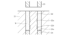
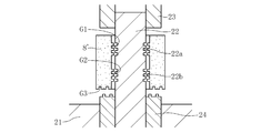
- the compacting process is performed using a forming mold shown in FIG.
- the forming mold includes a die 21, a core rod 22, an upper punch 23 and a lower punch 24.
- molding dies 22a and 22b having shapes corresponding to the dynamic pressure grooves G1 and G2 are provided.
- a molding die 24a having a shape corresponding to the dynamic pressure groove G3 is provided.
- a molding die having a shape corresponding to the axial groove 8d1 is provided on the inner peripheral surface of the die 21, and an annular groove 8c1 and a radial groove 8c2 are formed on the lower surface of the upper punch 23.
- a mold having a corresponding shape is provided.
- the raw material powder M is filled in the cavity defined by the die 21, the core rod 22, and the lower punch 24.
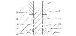
- the upper punch 23 is lowered to compress the raw material powder M to form a green compact 8 '.
- the dynamic pressure grooves G1 and G2 are formed on the inner peripheral surface of the green compact 8 ′ by the molds 22a and 22b of the core rod 22, and the green compact 8 ′ by the mold 24a of the lower punch 24.
- a dynamic pressure groove G3 is formed on the lower end surface of the lower surface.
- the dynamic pressure groove G3 on the lower end face of the green compact 8 ' may be formed in a separate process.
- the green compact 8 ' is discharged from the inner periphery of the die 21, so that the force directed to the inner diameter applied to the green compact 8' is released, and the green compact 8 'is spring-loaded. Back occurs.
- the inner peripheral surface of the green compact 8 ′ increases in diameter, and the green compact 8 ′ is released from the molds 22 a and 22 b of the core rod 22.
- the higher the density the higher the strength.
- an oxidizing gas such as air cannot penetrate into the green compact. Since the formation of the oxide film is limited to the very surface layer of the green compact, although the strength is improved, it is not preferable.
- the green density is 7.2 g / cm 3 or less (true density ratio 91% or less), preferably 7.0 g / cm 3 or less (true density ratio 89% or less).
- the green density should be 5.8 g / cm 3 or more (true density ratio 74% or more), preferably 6.0 g / cm 3 or more (true density ratio 76% or more).
- the dust density is set to 6.3 g / cm 3 or more (true density ratio).
- the measurement of a compacting density is based on the dimension measuring method. Further, the density of the green compact remains almost unchanged even after the subsequent degreasing process and oxidation process.
- the degreasing process is a process in which the green compact is heated to remove (dewax) the molding lubricant contained in the green compact.
- the degreasing step is performed at a temperature higher than the decomposition temperature of the molding lubricant and lower than the oxidation step described later, and is heated at 300 to 400 ° C. for 60 to 120 minutes, for example.
- the green compact 8 ′ before degreasing is provided with a molding lubricant 14 in the gaps between the iron particles 11, but by performing a degreasing step, FIG.
- the molding lubricant 14 disappears, and a green compact 8 ′ composed only of iron particles 11 is obtained.
- the lubricant component contained in the green compact is decomposed and is not included in the sintered product.
- the lubricant component may remain depending on the density of the green compact, the oxidation treatment temperature, and the holding time. Therefore, it is desirable to take a technique in which a degreasing process for decomposing and removing the lubricant component is provided in advance prior to the oxidation process, and the oxidation process is continuously performed in the same atmosphere after the degreasing process.
- the degreasing step may be performed in an atmosphere (for example, an inert gas, a reducing gas, or in a vacuum) different from the oxidation step using a separate heating device.
- the green compact is heated in an oxidizing atmosphere.
- the oxide film 12 is generated on the surface of each particle 11 of the metal powder (iron powder), and the particles 11 are bonded to each other through the oxide film 12 to increase the strength.
- an oxidized green compact 8 ′′ is obtained.
- an oxide film generated on the surface of each particle of the metal powder spreads between the iron particles 11 to form a network by the oxidation process.
- the strength of the oxidized green compact 8 ′′ is increased by replacing the conventional bonding force by sintering at a high temperature.
- not all particles of iron powder as a main component are bonded via an oxide film, but some particles are directly in contact with each other without an oxide film and fused. is doing.
- the formation of the oxide film 12 fills at least a part of the internal pores of the oxidized green compact 8 ′′. At this time, at least a part of the opening on the surface of the oxidized green compact 8 ′′ is formed by the oxide film 12. Communication with the internal pores 13b is blocked. As a result, a large number of openings 13a whose inner side is closed with the oxide film 12 are formed on the surface of the oxidized green compact 8 ′′ (see FIG. 5).
- the processing conditions (heating temperature, heating time, heating atmosphere) of the above-described oxidation treatment are such that the strength required for a dynamic pressure bearing is imparted to the oxidized green compact 8 ′′, and the oxide coating 12 provides the oxidized green compact.
- the oil content of the body 8 ′′ is set to 4 vol% or less, and the surface opening ratio is set to 40% or more.
- the heating temperature in the oxidation step of the present embodiment is set to 350 ° C. or higher, preferably 400 ° C. or higher. Further, if the heating temperature is too high, the dimensional change of the green compact becomes large, so the heating temperature is set to 600 ° C. or lower, preferably 550 ° C. or lower.
- the heating time is appropriately set in the range of 5 minutes to 2 hours, for example, 10 to 20 minutes.
- the oxidized green compact 8 ′′ has a strength required for the bearing sleeve 8, specifically, a crushing strength of 120 MPa or more, preferably 150 MPa or more.
- the heating atmosphere is an oxidizing atmosphere to promote aggressive oxidation.
- an oxidizing atmosphere in which the generation rate of the oxide film is lower than that of the water vapor atmosphere.
- heating is preferably performed in an atmosphere of air or oxygen, or an oxidizing gas in which an inert gas such as nitrogen or argon is mixed, and most preferably heating is performed in an air atmosphere.
- the oxygen fraction in the heating atmosphere is preferably 2 vol% or more.
- the iron oxide film formed on the surface of the iron powder is made of Fe 3 O 4 , Fe 2 O 3 , FeO or the like.
- the ratio of these oxide coatings varies depending on the material and processing conditions. For example, when the green compact is heated in a water vapor atmosphere, the oxide film becomes a single phase consisting essentially of Fe 3 O 4 . On the other hand, when the green compact is heated in an air atmosphere, the oxide film becomes Fe 3 O 4 or Fe 2 O 3 or a mixed phase thereof. Therefore, the composition of the oxide film formed on the oxidized green compact is analyzed, and if the oxide film contains Fe 2 O 3 , it is estimated that the green powder was oxidized in an air atmosphere. be able to.
- Strengthening by the above-mentioned oxidation process is a material (iron-based, copper-based, iron-copper-based, iron, copper, or a mixture of both of them in various proportions used in conventional general sintered members. Alternatively, it can be applied to a green compact of copper-iron. However, it is preferable that the metal powder consists of only a single type (for example, iron powder) because the thickness of the oxide film and the adhesion with the particles can be made uniform.
- the oxidation process described above has a lower processing temperature than the conventional sintering process at a high temperature, the dimensional change of the green compact before and after the processing is small. For this reason, a decrease in the dimensional accuracy of the oxidized green compact, particularly the dimensional accuracy of the dynamic pressure groove (groove depth, etc.) can be suppressed, and the required accuracy can be satisfied without sizing.
- the dynamic pressure groove is formed at the same time as the green compact is formed in the green compacting process, the dimensional change of the green compact due to the subsequent oxidation process is suppressed, so that The dimensional accuracy (groove depth, etc.) of the peripheral surface and the dynamic pressure groove is maintained.
- the above oxidation process can be applied regardless of the shape and size of the green compact. Further, since the surface of the oxidized green compact is covered with an oxide film, the antirust effect is high, and in some cases, the antirust treatment is unnecessary. In addition, since the processing temperature of the oxidation process is relatively low, an additive that denatures and decomposes at a temperature exceeding this processing temperature (for example, a material having slidability and lubricity) is added to enhance the functionality of the product. It is also possible to plan.
- the oil impregnation step is a step of impregnating lubricating oil into the internal pores of the oxidized green compact. Specifically, after the oxidized green compact is immersed in oil under a reduced pressure environment, the pressure is returned to atmospheric pressure, so that the oil enters the internal pores from the opening on the surface of the oxidized green compact. Thus, the bearing sleeve 8 according to this embodiment is completed. Note that the oil-impregnating step may be omitted, and the oxidized green compact that is not impregnated with oil may be used as the bearing sleeve 8.
- the internal pores of the bearing sleeve 8 are filled when oil is filled into the internal space of the fluid dynamic pressure bearing device 1 by vacuum impregnation or the like. Is impregnated with oil.
- the embodiment of the present invention is not limited to the above.
- the bearing sleeve 8 is provided with both the radial bearing surface and the thrust bearing surface.
- the present invention is not limited to this, and only one of the radial bearing surface or the thrust bearing surface is provided.
- the present invention may be applied to a slide bearing.
- the slide bearing according to the present invention may be applied as the bottom portion 7b (thrust bush) of the housing 7 described above.
- a perfect circle bearing may be configured with both the inner peripheral surface 8a of the bearing sleeve 8 and the outer peripheral surface 2a1 of the shaft member 2 as cylindrical surfaces.
- a dynamic pressure is generated in the oil film in the bearing gap between the bearing sleeve 8 and the shaft member 2 due to the swing of the shaft member 2, and a fluid dynamic pressure bearing that supports the shaft in a floating manner is configured by this dynamic pressure.
- Such a fluid dynamic pressure bearing is applied when supporting a shaft that rotates at a relatively high speed, but is not limited to this, and a counterpart material that rotates at a relatively low speed or a counterpart material that swings or linearly moves.
- the slide bearing of the present invention can also be applied as a bearing that is slidably supported via a lubricating film.
- the bearing sleeve 8 (dynamic pressure bearing) is a porous oil-impregnated bearing and is incorporated in the full-fill type fluid dynamic pressure bearing device 1 filled with oil is shown. It is not limited to this.
- the bearing sleeve 8 may be incorporated in a partial fill type fluid dynamic bearing device in which air and oil are mixed.
- the bearing sleeve 8 can be used in a state where the amount of oil impregnated in the internal pores is lower than that in the above embodiment, or in a state where the oil is not positively impregnated in the internal pores.
- the side portion 7a and the seal portion 9 of the housing 7 are configured as a single component, and the bottom portion 7b of the housing 7 is formed as a separate body.
- the side part 7a and the bottom part 7b may be formed of a single part, and the seal part 9 may be a separate body.
- the side portion 7a of the housing 7, the bottom portion 7b of the housing 7, and the seal portion 9 may be separated.
- the fluid dynamic pressure bearing device having a full-fill structure in which the oil surface is formed only at one place (in the seal space S) is shown.
- the slide bearing according to the present invention may be incorporated in the fluid dynamic bearing device.
- the slide bearing (bearing sleeve 8) is fixed and the mating member (shaft member 2) rotates is shown.
- the mating member is fixed and the sliding bearing is fixed. It may be rotated.
- the lubricating fluid is oil.
- grease, magnetic fluid, air, or the like may be used as the lubricating fluid.
- the slide bearing according to the present invention can be used by being incorporated not only in a spindle motor for a disk drive device such as an HDD but also in a fan motor for a cooling fan or a polygon scanner motor for a laser beam printer.
- the test piece (oxidized green compact) has the same configuration as the sliding bearing (bearing sleeve 8) of the above embodiment, and is composed of iron particles and an oxide coating formed on the surface thereof.
- the oil content is measured according to JIS Z 2501: 2000.
- FIG. 11 shows the measurement results of the oil content of each test piece. According to this figure, even if the true density ratio is about 80%, the oil content is less than half (for example, 4 vol% or less) with respect to 10 vol% which is the lower limit value of the oil content of a general sintered oil-impregnated bearing. Further, when the true density ratio is 85% or more, the oil content is almost 0 vol% (2 vol% or less). From the above, it has been clarified that the oil content can be sufficiently suppressed by degreasing and oxidizing the green compact.
- the green compact made of iron powder and molding lubricant was subjected to degreasing and oxidation treatments to produce a slide bearing according to the example.
- the plain bearing of the example has the same configuration as the bearing sleeve 8 (see FIGS. 3 and 4) of the above embodiment, the crushing strength is 150 MPa or more, the oil content is 4 vol% or less, the surface opening of the bearing surface The rate is 40% or more.
- a conventional plain bearing made of sintered copper-based metal was used as a comparative example.
- the plain bearing of the comparative example has the same shape as the bearing sleeve 8 of the above embodiment, but the manufacturing method is different from the examples.
- the oil film formation rate was measured by incorporating the slide bearings of Examples and Comparative Examples into motors and measuring the amount of current flowing between the shaft and the slide bearing while rotating each motor. Specifically, in a normal temperature (25 ° C.) environment, while rotating the motor at 2000 r / min, the shaft is held upright in the vertical direction, and the shaft is swung between the vertical direction and the horizontal direction. This state was repeated alternately every 2 seconds, and the oil film formation rate at this time was measured.
- Example 1 and 2 A test piece made of a cylindrical green compact produced by the method according to the present invention (Examples 1 and 2) and a test piece made of a cylindrical sintered body produced by a conventional method (comparative example) were prepared. did. Specifically, Examples 1 and 2 were manufactured through a degreasing process and an oxidation process after molding a green compact having dynamic pressure grooves. In the comparative example, after a cylindrical green compact was molded, the green compact was sintered to obtain a sintered body, and the sintered body was further sized to form dynamic pressure grooves. Examples 1 and 2 are both made of iron (including oxide coating), and the comparative examples are made of copper and iron.
- Example 1 the relative density with respect to the true density is less than 80% (specifically 6.2 g / cm3), and in Example 2, the relative density is 80% or more (specifically 6.7 g / cm3). is there.
- Each test piece has an inner diameter of ⁇ 1.5 mm, an outer diameter of ⁇ 3 mm, and an axial width of 3.3 mm.
- Example 1, 2, and the comparative example each item was measured and calculated about three test pieces, respectively, and the average value was employ
- the crushing strength was measured and calculated according to the method described in JIS Z 2507.
- the crushing strength refers to the strength of a cylindrical specimen obtained by a certain method from the crushing load.
- the crushing load refers to compressing the cylindrical specimen with two surfaces parallel to the axis and starting cracks.
- the load when The evaluation standard of crushing strength is as follows. ⁇ 120 MPa: ⁇ 120 to 150 MPa: ⁇ 150 MPa ⁇ : ⁇
- the dimensional change rate is determined by measuring the inner diameter, outer diameter, and axial width before and after the heat treatment (degreasing and oxidizing step in the example, sintering step in the comparative example) of each test piece, and using the following formula: Was calculated.
- Dimensional change rate (%) ⁇ Dimension of test piece after heating (mm) ⁇ Dimension of test piece before heating (mm) ⁇ ⁇ 100 / Dimension of test piece before heating (mm)
- the evaluation criteria for the dimensional change rate are as follows. ⁇ 0.4%: ⁇ 0.4 to 1.0%: ⁇ 1.0% ⁇ : ⁇
- the depth of the dynamic pressure groove was measured using a roundness meter. Specifically, a profile in the circumferential direction of the outer peripheral surface of the test piece is measured with a roundness meter at an axial position where hills and grooves alternately appear in the circumferential direction of the outer peripheral surface of the test piece. This profile is converted into a straight line, and the maximum difference in height (radial position) between the adjacent groove and hill is defined as the depth of the dynamic pressure groove.
- the depth of the dynamic pressure groove of the test piece is measured by the number of the dynamic pressure grooves (see h11 to h14 and h21 to h24 in FIG. 14), and the depth of each dynamic pressure groove is evaluated.
- the evaluation criteria for the depth of the dynamic pressure groove are as follows. ⁇ 3 ⁇ m: ⁇ 3-6 ⁇ m: ⁇ 6 ⁇ m ⁇ : ⁇
- the comparative example in which the green compact was sintered has a large dimensional change rate before and after sintering. Further, since the sintered body of the comparative example has a small amount of spring back after forming the dynamic pressure groove, the depth of the dynamic pressure groove has to be reduced.
- Examples 1 and 2 in which the green compact was not subjected to sintering treatment and subjected to oxidation treatment at a relatively low temperature had a small dimensional change rate before and after the oxidation treatment, and Example 2 having a high density had dimensions. The rate of change is particularly small. Therefore, Examples 1 and 2 can maintain dimensional accuracy without sizing.
- the dynamic pressure groove can be deepened. Specifically, the depth of the dynamic pressure groove is deeper than 3 ⁇ m, that is, the ratio h / d between the depth h ( ⁇ m) of the dynamic pressure groove and the inner diameter d (mm) can be made larger than 2. Furthermore, both Examples 1 and 2 have a crushing strength of 150 MPa or more required as a dynamic pressure bearing. As described above, according to the present invention, it has been confirmed that the dynamic pressure groove can be made deeper than a conventional dynamic pressure bearing made of a sintered body while ensuring strength and dimensional accuracy.
- test Piece Three types of green compacts with different raw material powders are molded, and each green compact is heated in an air atmosphere to produce three types of oxidized green compacts in which metal powder particles are bonded with an oxide coating (test Piece).
- test Piece a test piece made only of reduced iron powder was used in Example 1
- test piece made only of atomized iron powder was used in Example 2
- test piece made of copper powder and 40% reduced iron powder was used as a comparative example.
- Tables 1 and 2 below The evaluation criteria of the crushing strength and the dimensional change rate of each test piece are shown in Tables 1 and 2 below, and the test results are shown in Table 3 below.
- the crushing strength was measured by the method described in JIS Z 2507: 2000.
- the dimensional change rate is a ratio of dimensional change before and after the oxidation treatment, and was calculated based on the following equation.
- Dimensional change rate (%) ⁇ (size after oxidation treatment ⁇ size before oxidation treatment) / size before oxidation treatment ⁇ ⁇ 100
- Fluid dynamic pressure bearing apparatus 2 Shaft member 7 Housing 8 Bearing sleeve (slide bearing) 8 'Compact 8 "Oxide compact 9 Seal part 11 Iron particles 12 Oxide coating 13a Opening 13b Internal pore 14 Molding lubricant A Radial bearing surface B, C Thrust bearing surface G1, G2 (Radial) dynamic pressure Groove G3 (Thrust) Dynamic pressure grooves R1, R2 Radial bearing portion T1, T2 Thrust bearing portion S Seal space
Landscapes
- Engineering & Computer Science (AREA)
- General Engineering & Computer Science (AREA)
- Mechanical Engineering (AREA)
- Manufacturing & Machinery (AREA)
- Power Engineering (AREA)
- Metallurgy (AREA)
- Chemical & Material Sciences (AREA)
- Oil, Petroleum & Natural Gas (AREA)
- Physics & Mathematics (AREA)
- Fluid Mechanics (AREA)
- Sliding-Contact Bearings (AREA)
Abstract
すべり軸受(軸受スリーブ(8))は、金属粉末の粒子(11)の表面に形成された酸化物被膜(12)により粒子(11)同士を結合した酸化圧粉体を備える。酸化圧粉体には、支持すべき相手材(軸部材(2))と潤滑膜を介して摺動する軸受面(A、B)が設けられる。軸受面(A、B)には、酸化物被膜(12)により内部気孔(13b)との連通が遮断された多数の開口部(13a)が設けられる。
Description
本発明は、支持すべき相手材と潤滑膜を介して摺動するすべり軸受に関する。
HDD用のスピンドルモータや、レーザビームプリンタ用のポリゴンスキャナモータ、冷却ファン用のファンモータなどの小型モータの回転支持軸受には、すべり軸受の一種である焼結含油軸受が使用されることがある。焼結含油軸受は、内部気孔に油(又はグリース。以下同様。)が含浸されており、この油が軸受面から滲み出すことで、軸受面と軸との摺動部に油を供給して潤滑性を高めることができる。
しかし、軸受隙間の油膜の圧力が高まると、油の一部が焼結含油軸受の軸受面の開口部から内部気孔を介して外部へ抜けてしまうため、油膜の圧力が低下して負荷容量が低下してしまう。このような軸受面の開口部からの圧力抜けを抑制するために、例えば下記の特許文献1には、軸受面に金型(例えばマンドレル)を摺動させることで軸受面の開口部を封孔する技術が示されている。
<第1の目的>
しかし、上記のように金型を摺動させて軸受面を封孔すると、軸受面に傷がつきやすく、品質が低下するおそれがある。また、軸受面を封孔するための工程および金型が増えるため、コストアップとなる。
しかし、上記のように金型を摺動させて軸受面を封孔すると、軸受面に傷がつきやすく、品質が低下するおそれがある。また、軸受面を封孔するための工程および金型が増えるため、コストアップとなる。
上記のほかにも、軸受面の開口部からの圧力抜けを抑制する手段として、例えば、圧粉体の成形圧力を高めて密度を上げることにより内部気孔の体積を減らしたり、溶融樹脂や溶融金属を浸み込ませて内部気孔を埋めたりする方法がある。しかし、圧粉体の成形圧力を高めることによる密度向上は、プレス機の能力、金型の強度、生産性などの面で限界がある。また、溶融樹脂や溶融金属による封孔は、軸受面の精度を維持することが困難である上、多大な工数がかかってコストアップを招く。
また、軸受面の開口部を完全に封孔したり、溶製鋼などの気孔を有さない材料ですべり軸受を形成したりして軸受面を平滑にすれば、油膜圧力の低下は防止できる。しかし、この場合、内部気孔からの油の供給が無くなるため、軸受面と軸との摺動部の油が枯渇しやすくなり、軸受面と軸との接触による焼き付きが生じるおそれがある。
そこで、本発明は、コストアップを招くことなく、軸受面からの圧力抜けを抑制して負荷容量を高めると共に、軸受面と相手材(軸)との摺動部における潤滑膜切れを防止して焼き付きを防止することを第1の目的とする。
<第2の目的>
動圧軸受は、相対回転する軸との間の軸受隙間に生じる流体圧力で、軸を非接触支持するものである。動圧軸受の内周面には、軸受隙間に満たされた油(又はグリース、以下同様)等の潤滑流体に動圧を発生させるラジアル動圧発生部(例えば動圧溝)が形成される。
動圧軸受は、相対回転する軸との間の軸受隙間に生じる流体圧力で、軸を非接触支持するものである。動圧軸受の内周面には、軸受隙間に満たされた油(又はグリース、以下同様)等の潤滑流体に動圧を発生させるラジアル動圧発生部(例えば動圧溝)が形成される。
動圧溝は、例えば、軸受素材に金型を押し付けることにより型成形される。例えば上記特許文献2には、焼結後のサイジングにより、円筒状の焼結体の内周面に動圧溝を型成形する方法が示されている。具体的には、動圧溝の形状に対応した成形型を有するコアロッドを円筒状の焼結体の内周に挿入し、この状態で焼結体およびコアロッドをダイに圧入することにより焼結体の内周面をコアロッドの成形型に押し付けて動圧溝を成形する。その後、焼結体およびコアロッドを上昇させてダイから排出することにより、ダイによる圧迫力が解放されて焼結体がスプリングバックにより拡径し、コアロッドから焼結体の内周面が離型される。
上記のように動圧軸受を焼結金属で形成する場合、金属粉末を圧縮成形して圧粉体を形成した後、この圧粉体に対し高温(鉄系材料の場合、800~1300℃)での焼結処理が施されるが、これにより寸法精度が大きく崩れてしまう。このため、焼結体に、寸法矯正及び動圧溝の形成を目的とした上記のサイジングを施すことが必要となり、コスト高を招く。
例えば、上記特許文献3では、動圧溝を型成形した圧粉体を水蒸気雰囲気中で加熱することにより、圧粉体を構成する金属粉末の粒子の表面に酸化物被膜を形成し、この酸化物被膜により前記粒子同士を結合することで、強度向上を図っている。このように酸化処理が施された圧粉体(以下、「酸化圧粉体」とも言う。)は、焼結体と比べると強度は劣るが、粒子同士が酸化物被膜で結合されているため、ある程度の強度を有する。この酸化処理時の加熱温度は、従来の焼結温度よりも格段に低いため(例えば350~600℃程度)、酸化圧粉体、ひいては動圧溝の寸法変化が抑えられ、サイジングを施さなくても、要求される寸法精度を満足することができる。
しかし、本発明者らの検証によれば、上記特許文献3のように、動圧溝を有する圧粉体に水蒸気処理を施すことで、酸化圧粉体の表面が粗くなることが判明した。具体的には、圧粉体に水蒸気処理を施すと、酸化物被膜の生成速度が速いため、圧粉体の表面に形成される酸化物被膜が厚くなり、酸化圧粉体の表面、特に軸受面の粗さやうねり(特に粗さ)が大きくなる。動圧軸受の軸受面は、極小の軸受隙間を介して相手材(軸)と対向するため、軸受面の粗さやうねりが大きくなると相手材に接触しやすくなり、異音発生の原因となるおそれがある。また、軸の回転開始直後や停止直前などの低速回転時には、軸受隙間の潤滑膜の圧力が低いため軸受面と軸とが摺動するが、このとき軸受面の粗さやうねりが大きいと、軸受面および相手材の摩耗を促進する。
そこで、本発明は、動圧溝を有する圧粉体に酸化処理を施してなる動圧軸受において、軸受面の面精度を高めて、異音の発生や、軸受面および相手材の摩耗を抑えることを第2の目的とする。
<第3の目的>
また、動圧軸受の内周面と軸の外周面との間には、数μm程度の軸受隙間が形成されるため、動圧軸受の内周面は高精度に成形する必要がある。また、動圧軸受の内周面には、軸受隙間の幅と同程度の深さの動圧溝が成形されるが、この動圧溝の寸法精度が崩れると、軸受隙間の流体圧が十分に高まらず、負荷容量や軸受剛性の低下を招く。このため、動圧軸受の内周面及び動圧溝は、高い寸法精度が要求される。
また、動圧軸受の内周面と軸の外周面との間には、数μm程度の軸受隙間が形成されるため、動圧軸受の内周面は高精度に成形する必要がある。また、動圧軸受の内周面には、軸受隙間の幅と同程度の深さの動圧溝が成形されるが、この動圧溝の寸法精度が崩れると、軸受隙間の流体圧が十分に高まらず、負荷容量や軸受剛性の低下を招く。このため、動圧軸受の内周面及び動圧溝は、高い寸法精度が要求される。
上記特許文献3では、銅粉と鉄粉とを混合した原料粉末により圧粉体が形成されている。しかし、本発明者の検証によれば、複数種の金属粉末を含む圧粉体に酸化処理を施すと、金属の種類によって酸化物被膜の形成状態に差異が生じるため、金属粉末の粒子表面に形成される酸化物被膜の厚さや、酸化物被膜と粒子との密着性が不均一となり、その結果、酸化圧粉体の寸法精度が悪化することが明らかになった。
そこで、本発明は、酸化圧粉体からなる動圧軸受の寸法精度を高めることを第3の目的とする。
<第4の目的>
流体動圧軸受装置は、軸と軸受部材との相対回転に伴って、これらの間の軸受隙間に形成される油膜の圧力により、軸を相対回転自在に非接触支持するものである。流体動圧軸受装置は、HDD、ポリゴンミラーモータ、小型クーリングファンモータなど、小型で高速、高精度回転用の軸受装置として広く用いられている。
流体動圧軸受装置は、軸と軸受部材との相対回転に伴って、これらの間の軸受隙間に形成される油膜の圧力により、軸を相対回転自在に非接触支持するものである。流体動圧軸受装置は、HDD、ポリゴンミラーモータ、小型クーリングファンモータなど、小型で高速、高精度回転用の軸受装置として広く用いられている。
流体動圧軸受装置は、内部に油(又はグリース、以下同様)が完全に充填されたフルフィル構造と、内部に空気層が存在するパーシャルフィル構造とに大別される。
フルフィルタイプの流体動圧軸受装置は、パーシャルフィルの流体動圧軸受装置と比べて油面の位置が変動しにくいため、油漏れは比較的生じにくいが、油漏れを確実に防止するためにシール構造を設けることが一般的である。例えば、特許文献4では、ハウジングの開口部に設けたシール部材の内周面と、軸部材の外周面に設けたテーパ面との間に、断面楔状のシール空間(いわゆる、テーパシール)を形成している。テーパシールでは、毛細管作用により油面をシール空間内に維持すると共に、温度上昇に伴う油の体積増加をシール空間で緩衝することにより、油の流出を防止している。
上記のようなシール空間は、温度変化に伴う油の体積変化を吸収可能な容積が必要となるため、流体動圧軸受装置の内部に充填される油の量が多いほど、シール空間の容積を大きくする必要が生じる。特に、軸受部材として、焼結金属等の多孔質材からなる多孔質含油軸受を使用した場合、軸受部材の内部気孔にも油が含浸されるため、その分、油量が増えてしまい、シール空間の容積のさらなる拡大を招く。
一方、流体動圧軸受装置が組み込まれる機器の小型化、薄型化に伴い、流体動圧軸受装置の全長(軸方向長さ)はおのずと制限される。上記の特許文献1に示されている流体動圧軸受装置のように、シール空間とラジアル軸受隙間とが軸方向に並べて設けられている場合、シール空間の容積を確保するためにシール空間の軸方向寸法を大きくすると、ラジアル軸受隙間の軸方向長さ(軸受スパン)を十分に確保することができなくなり、軸受の負荷容量や剛性の低下を招くおそれがある。
例えば、焼結金属からなる軸受部材の内部気孔を少なくすれば、軸受部材の内部に含浸される油量、ひいては、流体動圧軸受装置の内部に充填される総油量が減じられるため、シール空間の容積を縮小し、シール空間の軸方向長さを短くすることができる。軸受部材の内部気孔を少なくする方法としては、例えば圧粉体の密度を上げることが考えられるが、この場合、圧粉体を成形する際に大きな成形圧力が必要となるため、成形プレス機の大型化等によるコストアップを招く。
以上のような事情から、本発明は、多孔質含油軸受を有する流体動圧軸受装置において、コストアップを招くことなく、内部に充填される油量を減じることによりシール空間の軸方向寸法を縮小し、もって流体動圧軸受装置の軸方向寸法の縮小、あるいは軸受スパンの拡大による負荷容量及び軸受剛性の向上を図ることを第4の目的とする。
<本願第1発明>
前記第1の目的を達成するためになされた本願第1発明は、金属粉末の粒子の表面に形成された酸化物被膜により前記粒子同士が結合された酸化圧粉体からなり、支持すべき相手材と潤滑膜を介して摺動する軸受面を有するすべり軸受において、前記軸受面に、前記酸化物被膜により内部気孔との連通が遮断された多数の開口部を有することを特徴とする。
前記第1の目的を達成するためになされた本願第1発明は、金属粉末の粒子の表面に形成された酸化物被膜により前記粒子同士が結合された酸化圧粉体からなり、支持すべき相手材と潤滑膜を介して摺動する軸受面を有するすべり軸受において、前記軸受面に、前記酸化物被膜により内部気孔との連通が遮断された多数の開口部を有することを特徴とする。
本発明のすべり軸受は、一般的な焼結軸受のように圧粉体を高温(例えば850℃)で焼結するのではなく、圧粉体に比較的低温(例えば500℃)での加熱処理を施すことにより、圧粉体を構成する金属粉末の粒子の表面に酸化物被膜を生成させ、この酸化物被膜により粒子同士を結合したものである。この場合、酸化物被膜により酸化圧粉体の内部気孔の少なくとも一部が埋められることで、酸化圧粉体の表面から内部に油が抜けにくくなるため、別途の封孔処理を行わなくても、軸受面からの圧力抜けを抑制して負荷容量を高めることができる。
また、上記の酸化物被膜により、酸化圧粉体の表面の開口部が完全に封孔されて軸受面が平滑となるわけではなく、酸化圧粉体の表面には、酸化物被膜により内部気孔との連通が遮断された多数の開口部が残っている。この開口部は、油を保持する油溜まりとして機能し、開口部に保持された油が、軸受面と相手材との摺動部に供給されることで、摺動部における油膜切れを防止できる。尚、「内部気孔」とは、酸化圧粉体の表面に露出していない粒子あるいはその表面に形成された酸化物被膜で形成された気孔を意味する。
上記のすべり軸受は、含油率を4vol%以下、軸受面の表面開口率を40%以上とすることが好ましい。尚、表面開口率とは、上記のような内部気孔と連通していない開口部だけでなく、内部気孔と連通した開口部を含む、軸受面におけるすべての開口部の面積率である。
また、上記のすべり軸受は、通油度が0.01g/10min以下とすることが好ましい。尚、通油度は、すべり軸受の表面(例えば内周面)に油を接触させ、この油に所定圧力(ここでは0.4MPa)を負荷した状態で10分間保持したときに、すべり軸受の反対側の表面(例えば外周面)の開口部から滲み出した油の総重量を測定することにより求められる。
前記軸受面は、例えば、動圧溝等を有さない平滑な円筒面とすることができる。このすべり軸受は、動圧溝が形成された軸部材の外周面と対向させて流体動圧軸受を構成したり、軸部材の円筒面状外周面と対向させて真円軸受を構成したりすることができる。
また、前記軸受面に、動圧溝を型成形してもよい。このすべり軸受は、例えば、軸部材の平滑な外周面あるいは端面と対向させて流体動圧軸受を構成することができる。
上記のすべり軸受は、例えば流体動圧軸受装置に組み込むことができる。具体的には、上記のすべり軸受と、前記すべり軸受の内周に挿入された前記相手材としての軸部材とを備え、前記すべり軸受の軸受面と前記軸部材の外周面との間のラジアル軸受隙間における潤滑膜の圧力で前記軸部材を相対回転自在に非接触支持する流体動圧軸受装置を得ることができる。
<本願第2発明>
前記第2の目的を達成するためになされた本願第2発明は、金属粉末を圧縮して圧粉体を成形すると同時に、前記圧粉体の内周面に動圧溝を成形する工程と、前記圧粉体を空気雰囲気中で加熱して、前記圧粉体を構成する金属粉末の粒子の表面に酸化物被膜を形成し、この酸化物被膜により前記粒子同士を結合する工程とを有する動圧軸受の製造方法を提供する。
前記第2の目的を達成するためになされた本願第2発明は、金属粉末を圧縮して圧粉体を成形すると同時に、前記圧粉体の内周面に動圧溝を成形する工程と、前記圧粉体を空気雰囲気中で加熱して、前記圧粉体を構成する金属粉末の粒子の表面に酸化物被膜を形成し、この酸化物被膜により前記粒子同士を結合する工程とを有する動圧軸受の製造方法を提供する。
このように、圧粉体の酸化処理を空気雰囲気で行うことにより、圧粉体の表面に酸化被膜がマイルドに形成されるため、酸化圧粉体の表面の粗さやうねりが抑えられる。例えば、図14の上段に示す、空気雰囲気中で酸化処理を施した酸化圧粉体(実施例)の内周面と、図14の下段に示す、水蒸気雰囲気中で酸化処理を施した酸化圧粉体(比較例)の内周面とを比較すると、実施例は、比較例と比べて、丘部及び溝部共に表面状態が良好である。このように、軸受面の粗さやうねりが小さいことで、異音の発生や、軸受面および相手材の摩耗を防止することができる。尚、図14(A)(B)は、酸化圧粉体の内周面の周方向のプロファイルを直線状に変換して示したものであり、図中上側が溝部、下側が丘部を表している。
ところで、上記特許文献2のように焼結体の内周面に動圧溝を型成形する場合、動圧溝の深さは、離型時の焼結体のスプリングバック量よりも小さくする必要がある。しかし、焼結体のスプリングバック量は小さいため、動圧溝の深さには限界があり、例えば内径1.5mmの動圧軸受の場合、動圧溝の深さは3μm程度が限界である。一方、動圧軸受の内周面と軸の外周面との間の軸受隙間の大きさは、流体圧力を確保するために、動圧溝の深さ以下に設定することが一般的である。従って、動圧溝の深さが3μmである場合、通常、軸受隙間は3μm以下に設定される。このように軸受隙間が小さいことで、軸の振れ回り時等に動圧軸受と軸とが接触しやすくなる。
これに対し、本発明では、圧粉体の成形と同時に動圧溝を成形する。圧粉体の離型時のスプリングバック量(内周面の拡径量)は、焼結体の離型時のスプリングバック量よりも大きいため、上記のように圧粉体に動圧溝を型成形することにより、焼結体に動圧溝を型成形する場合と比べて、動圧溝の深さを深くすることができる。具体的には、例えば、動圧溝の深さh(μm)と圧粉体の内径d(mm)との比h/dを2よりも大きくすることができる。
圧粉体の酸化処理時の加熱温度は、従来の焼結温度よりも格段に低い温度(例えば600℃以下)で足りる。これにより、圧粉体の寸法変化が抑えられるため、加熱後のサイジングを省略することができる。
上記の製造方法によれば、金属粉末の粒子の表面に空気雰囲気中で形成された酸化物被膜により前記粒子同士が結合された酸化圧粉体からなり、内周面に動圧溝が型成形された動圧軸受を得ることができる。
圧粉体を複数種の金属粉末で構成すると、粒子の表面に形成される酸化物被膜の厚さや基材との密着性などが異なるため、寸法精度や軸受特性が満足できないおそれがある。従って、上記の動圧軸受は、圧粉体の95wt%以上が単一種の金属(例えば鉄)であることが好ましい。
酸化圧粉体が主に鉄からなる場合、前記酸化物被膜はFe3O4、Fe2O3、FeO等からなる。例えば圧粉体を水蒸気雰囲気中で加熱した場合、酸化物被膜はほぼFe3O4のみの単一相となる。一方、圧粉体を空気雰囲気中で加熱した場合、酸化物被膜は、Fe3O4とFe2O3の混相となる。従って、鉄を主体とする酸化圧粉体において、酸化物被膜がFe3O4とFe2O3の混相であれば、空気雰囲気中での加熱により形成されたものであると推定することができる。
上記の動圧軸受は、例えば酸化圧粉体の内部気孔に油を含浸させて使用することができる。
上記の動圧軸受は、流体動圧軸受装置に組み込むことができる。具体的には、上記の動圧軸受と、前記動圧軸受の内周に挿入された軸部材とを備え、前記動圧軸受の内周面と前記軸部材の外周面との間のラジアル軸受隙間に生じる油膜の動圧作用で前記軸部材を相対回転自在に非接触支持する流体動圧軸受装置を得ることができる。
<本願第3発明>
前記第3の目的を達成するためになされた本願第3発明は、内周面にラジアル動圧発生部を有し、金属粉末の粒子の表面に形成された酸化物被膜を介して前記粒子同士が結合された酸化圧粉体からなる動圧軸受において、前記酸化圧粉体に含まれる金属粉末の99wt%以上が、単一種の金属粉末で構成されたことを特徴とする。
前記第3の目的を達成するためになされた本願第3発明は、内周面にラジアル動圧発生部を有し、金属粉末の粒子の表面に形成された酸化物被膜を介して前記粒子同士が結合された酸化圧粉体からなる動圧軸受において、前記酸化圧粉体に含まれる金属粉末の99wt%以上が、単一種の金属粉末で構成されたことを特徴とする。
また、本願第3発明は、単一種の金属粉末が95wt%以上を占める原料粉末を圧縮して圧粉体を成形すると同時に、該圧粉体の内周面にラジアル動圧発生部を成形する工程と、前記圧粉体を加熱して、前記圧粉体を構成する金属粉末の粒子の表面に酸化物被膜を形成し、この酸化物被膜を介して前記粒子同士を結合して酸化圧粉体を得る工程とを有する。
上記のように、本発明では、酸化圧粉体に含まれる金属粉末の99wt%以上を単一種の金属粉末で構成し、あるいは、圧粉体の原料粉末の95wt%以上を単一種の金属粉末で構成した。このように、圧粉体を、実質的に単一種の金属粉末で形成することにより、金属粉末の粒子表面に酸化物被膜を均一に形成することができるため、複数種の金属粉末を含む場合と比べて、加熱処理による圧粉体の寸法変化が抑えられ、動圧軸受(酸化圧粉体)の寸法精度、特に内周面及びラジアル動圧発生部(例えば動圧溝)の寸法精度が高められる。
尚、本発明で言う「単一種の金属粉末」とは、鉄粉や銅粉等の単一金属からなる粉末の他、例えば、各粒子が複数種の金属成分を有するプレアロイ粉の成分(組成)が同一の場合を含む。
動圧軸受の耐久性(耐摩耗性)や強度、酸化物被膜の形成のしやすさ等を考慮すると、上記の圧粉体を構成する単一種の金属粉末としては、鉄粉を用いることが好ましい。
一般的に、金属粉末の種類としては、還元粉、電解粉、アトマイズ粉などがある。電解粉は、粒子が樹枝形状であるため、粒子同士の絡み合いが多く、動圧軸受として必要な強度を得やすいが、樹枝形状の粒子表面に酸化物被膜を均一に形成することは困難である。アトマイズ粉は、粒子が略球状を成しているため、粒子表面に酸化物被膜が均一に形成されやすいが、粒子同士の絡み合いが少なく、動圧軸受として必要な強度を得ることが難しい。還元粉は、粒子内部に空隙を有しているため、圧縮成形により粒子同士が絡み合いやすく、強度を高めやすい。また、還元粉の粒子の形状は、比較的球形に近いため、粒子表面に酸化物被膜が均一に形成されやすい。以上より、上記の圧粉体を構成する単一種の金属粉末としては、還元粉を用いることが好ましい。
上記の動圧軸受と、動圧軸受の内周に挿入された軸部材と、動圧軸受の内周面と軸部材の外周面との間のラジアル軸受隙間に生じる油膜の動圧作用で軸部材を相対回転自在に支持するラジアル軸受部とを備えた流体動圧軸受装置は、動圧軸受の寸法精度が高いことにより、高い負荷容量及び軸受剛性を有する。
上記の流体動圧軸受装置と、前記ハウジングおよび前記軸部材のうち、回転側に設けられたロータマグネットと、前記ハウジングおよび前記軸部材のうち、固定側に設けられたステータコイルとを備えたモータは、高回転精度を有する。
前記圧粉体を空気雰囲気中で加熱することにより、水蒸気雰囲気中で加熱する場合と比べて、圧粉体の表面に酸化物被膜がマイルドに形成されるため、酸化圧粉体の表面の粗さやうねりが抑えられる。例えば、実質的に鉄粉のみからなる圧粉体を空気雰囲気中で加熱した場合、前記酸化物被膜は、例えばFe3O4又はFe2O3、あるいはこれらの混合体で形成される。
<本願第4発明>
前記第4の目的を達成するためになされた本願第4発明は、軸部材と、内周に前記軸部材が挿入された多孔質含油軸受と、前記多孔質含油軸受を内周に保持する有底筒状のハウジングと、前記ハウジングの開口部に設けられたシール部と、前記多孔質含油軸受の内周面と前記軸部材の外周面との間のラジアル軸受隙間に生じる油膜の動圧作用で前記軸部材を相対回転自在に支持するラジアル軸受部と、前記シール部の内周面と前記軸部材の外周面との間に形成され、前記ハウジングの内部に満たされた油と大気との界面を保持するシール空間とを備えた流体動圧軸受装置において、前記多孔質含油軸受が、金属粉末の粒子の表面に形成された酸化物被膜を介して前記粒子同士が結合された酸化圧粉体を有し、前記多孔質含油軸受の含油率が4vol%以下であることを特徴とする。
前記第4の目的を達成するためになされた本願第4発明は、軸部材と、内周に前記軸部材が挿入された多孔質含油軸受と、前記多孔質含油軸受を内周に保持する有底筒状のハウジングと、前記ハウジングの開口部に設けられたシール部と、前記多孔質含油軸受の内周面と前記軸部材の外周面との間のラジアル軸受隙間に生じる油膜の動圧作用で前記軸部材を相対回転自在に支持するラジアル軸受部と、前記シール部の内周面と前記軸部材の外周面との間に形成され、前記ハウジングの内部に満たされた油と大気との界面を保持するシール空間とを備えた流体動圧軸受装置において、前記多孔質含油軸受が、金属粉末の粒子の表面に形成された酸化物被膜を介して前記粒子同士が結合された酸化圧粉体を有し、前記多孔質含油軸受の含油率が4vol%以下であることを特徴とする。
本発明に係る流体動圧軸受装置の多孔質含油軸受は、一般的な焼結軸受のように圧粉体を高温(例えば850℃)で焼結するのではなく、圧粉体に比較的低温(例えば500℃)での加熱処理を施すことにより、圧粉体を構成する金属粉末の粒子の表面に酸化物被膜を生成させ、この酸化物被膜により粒子同士を結合したものである。この場合、酸化物被膜により酸化圧粉体の内部気孔の少なくとも一部が埋められて、酸化圧粉体の内部気孔が減じられるため、多孔質含油軸受の含油率を4vol%以下とすることができる。このように、多孔質含油軸受の内部に含浸される油量が減じられることで、流体動圧軸受装置の内部に充填される総油量が減じられる。これにより、油の体積変化を緩衝するシール空間の容積、特に、シール空間の軸方向寸法を縮小することができるため、流体動圧軸受装置の軸方向寸法の縮小、あるいは軸受スパンの拡大による負荷容量及び軸受剛性の向上を図ることができる。
例えば、複数種の金属粉末を含む圧粉体に酸化処理を施すと、金属の種類によって酸化物被膜の形成状態に差異が生じ、酸化物被膜の厚さや、酸化物被膜と粒子との密着性が不均一となるおそれがある。従って、上記の多孔質含油軸受に含まれる金属粉末は、実質的に単一種の金属粉末のみで構成することが好ましい。具体的には、多孔質含油軸受を構成する酸化圧粉体に含まれる金属粉末の99wt%以上を、単一種の金属粉末で構成することが好ましい。特に、多孔質含油軸受の耐久性(耐摩耗性)や強度、酸化物被膜の形成のしやすさ等を考慮すると、上記の単一種の金属粉末として鉄粉を用いることが好ましい。
上記の流体動圧軸受装置と、前記ハウジングおよび前記軸部材のうち、回転側に設けられたロータマグネットと、前記ハウジングおよび前記軸部材のうち、固定側に設けられたステータコイルとを備えたモータは、軸方向寸法の小型化、あるいは、回転精度の向上を図ることができる。
上記の多孔質含油軸受は、金属粉末を圧縮して圧粉体を成形する工程と、前記圧粉体を加熱して、前記圧粉体を構成する金属粉末の粒子の表面に酸化物被膜を形成し、この酸化物被膜を介して前記粒子同士を結合して酸化圧粉体を得る工程と、前記酸化圧粉体の内部気孔に油を含浸させ、含油率が4vol%以下の多孔質含油軸受を得る工程とを経て製造することができる。
前記圧粉体を空気雰囲気中で加熱することにより、水蒸気雰囲気中で加熱する場合と比べて、圧粉体の表面に酸化物被膜がマイルドに形成されるため、酸化圧粉体の表面の粗さやうねりが抑えられる。例えば、実質的に鉄粉のみからなる圧粉体を空気雰囲気中で加熱した場合、前記酸化物被膜は、例えばFe3O4又はFe2O3、あるいはこれらの混合体で形成される。
以上のように、本願第1発明では、すべり軸受(圧粉体)の内部気孔の少なくとも一部を酸化物被膜で埋めることで、軸受面からの圧力抜けを抑制して負荷容量を高めることができる。また、すべり軸受の軸受面に、油溜まりとなる多数の開口部が設けられることで、相手材との摺動部における油膜切れを防止して焼き付きを防止することができる。
また、本願第2発明によれば、動圧溝を有する圧粉体に酸化処理を施してなる動圧軸受において、軸受面の面精度を高めることができるため、異音の発生や、軸受面および相手材の摩耗を抑えることができる。
また、本願第3発明によれば、酸化圧粉体からなる動圧軸受の寸法精度を高めることができる。
また、本願第4発明では、酸化物被膜により酸化圧粉体の内部気孔を減じて、多孔質含油軸受の含油率を抑えることで、流体動圧軸受装置の内部に充填される総油量を減じることができるため、シール空間の軸方向寸法を縮小することができる。これにより、流体動圧軸受装置の軸方向寸法の縮小、あるいは軸受スパンの拡大による負荷容量及び軸受剛性の向上を図ることができる。
<本発明の実施形態>
以下、本発明の実施形態を図1~10に基づいて説明する。
以下、本発明の実施形態を図1~10に基づいて説明する。
図1に示すスピンドルモータは、HDD等のディスク駆動装置に用いられるものであり、軸部材2を回転自在に非接触支持する流体動圧軸受装置1と、軸部材2に装着されたディスクハブ3と、例えば半径方向のギャップを介して対向させたステータコイル4およびロータマグネット5とを備えている。ステータコイル4はケーシング6に取付けられ、ロータマグネット5はディスクハブ3に取付けられる。流体動圧軸受装置1のハウジング7は、ケーシング6の内周に装着される。ディスクハブ3には、磁気ディスク等のディスクDが所定枚数保持される。ステータコイル4に通電すると、ステータコイル4とロータマグネット5との間の電磁力でロータマグネット5が回転し、それによって、ディスクハブ3および軸部材2が一体となって回転する。
図2に示すように、流体動圧軸受装置1は、本発明の一実施形態に係るすべり軸受(動圧軸受)としての軸受スリーブ8と、軸受スリーブ8で支持される相手材としての軸部材2と、軸受スリーブ8を内周に保持する有底筒状のハウジング7と、ハウジング7の軸方向一端の開口部に設けられたシール部9とを有する。図示例では、ハウジング7とシール部9が一部品で構成されている。尚、以下の説明では、便宜上、軸方向でハウジング7の閉塞側を下側、ハウジング7の開口側を上側と言うが、これは流体動圧軸受装置1の使用態様を限定する趣旨ではない。
軸部材2は、軸部2aと、軸部2aの下端に設けられたフランジ部2bとを備える。軸部材2は、例えば金属で形成され、本実施形態では、軸部2aおよびフランジ部2bを含む軸部材2全体がステンレス鋼で一体に形成される。
軸受スリーブ8は円筒状をなし、内周面8aに、軸部材2の外周面2a1と対向するラジアル軸受面が設けられる。図示例では、軸受スリーブ8の内周面8aの軸方向に離隔した2箇所にラジアル軸受面Aが形成される。本実施形態では、ラジアル軸受面Aの内径が、φ3~5mmとされる。各ラジアル軸受面Aには動圧溝が形成され、本実施形態では、図3に示すように、各ラジアル軸受面Aにへリングボーン形状に配列された動圧溝G1,G2が設けられる。図中クロスハッチングで示す領域は、内径側に盛り上がった丘部を示している(図4においても同様)。
上側の動圧溝G1は軸方向で非対称な形状を成し、下側の動圧溝G2は軸方向で対称な形状を成している。軸方向非対称形状の上側の動圧溝G1により、ラジアル軸受隙間の油が軸方向に押し込まれ、ハウジング7の内部で油が強制的に循環される。ラジアル軸受面Aの軸方向間領域には、動圧溝G1、G2の溝底面と連続した円筒面が設けられる。尚、上下の動圧溝G1,G2の双方を軸方向対称形状としてもよい。また、上下の動圧溝G1,G2を軸方向で連続させたり、上下の動圧溝G1,G2の一方あるいは双方を省略したりしてもよい。また、ラジアル軸受面に、スパイラル形状の動圧溝や軸方向に延びる動圧溝を形成してもよい。また、軸受スリーブ8の内周面8a(ラジアル軸受面A)を円筒面として、軸部材2の外周面2a1に動圧溝を形成してもよい。
軸受スリーブ8の下側端面8bには、軸部材2のフランジ部2bの上側端面2b1と対向するスラスト軸受面Bが設けられる。スラスト軸受面Bには、図4に示すようなポンプインタイプのスパイラル形状の動圧溝G3が形成される。尚、動圧溝の形状として、ヘリングボーン形状や放射溝形状等を採用しても良い。また、軸受スリーブ8の下側端面8b(スラスト軸受面B)を平坦面として、軸部材2のフランジ部2bの上側端面2b1に動圧溝を形成してもよい。
軸受スリーブ8の上側端面8cには、図3に示すように、環状溝8c1と、環状溝8c1の内径側に設けられた複数の半径方向溝8c2とが形成される。軸受スリーブ8の外周面8dには、複数の軸方向溝8d1が円周方向等間隔に設けられる。これらの軸方向溝8d1、環状溝8c1、及び半径方向溝8c2等を介して、軸部材2のフランジ部2bの外径側の空間がシール空間Sと連通することで、この空間における負圧の発生が防止される。尚、特に必要が無ければ、環状溝8c1および半径方向溝8c2を省略して、軸受スリーブ8の上側端面8cを平坦面としてもよい。
軸受スリーブ8の表面は、動圧溝G1、G2、G3の溝底面や、丘部の頂面および側面を含め、全域が型成形された面となっている。軸受スリーブ8にはサイジングが施されておらず、軸受スリーブ8の表面に摺動痕は形成されていない。
軸受スリーブ8は、酸化処理が施された圧粉体、すなわち、金属粉末の粒子同士が酸化物被膜を介して結合された圧粉体(酸化圧粉体)の内部気孔に油を含浸させた多孔質含油軸受である。本実施形態の軸受スリーブ8は、例えば単一種の金属を95wt%以上含み、実質的に単一種の金属粉末からなる酸化圧粉体で構成される。具体的には、酸化圧粉体を構成する金属粉末の99wt%以上が、単一種の金属粉末(粒子表面の酸化物被膜を含む)で構成される。本実施形態では、軸受スリーブ8が、金属粉末として鉄粉(特に還元鉄粉)のみからなる酸化圧粉体で構成される。具体的に、軸受スリーブ8は、図5に示すように、鉄粒子11と、鉄粒子11の表面に形成された酸化物被膜12とからなる酸化圧粉体で構成される。鉄粒子11は、酸化物被膜12により互いに結合されている。詳しくは、各鉄粒子11の表面に形成された酸化物被膜12が、鉄粒子11間に行き渡ってネットワークを形成することにより、軸受スリーブ8の強度が確保されている。
軸受スリーブ8は、酸化物被膜12により鉄粒子11間の隙間(内部気孔)の少なくとも一部が埋められることで、気孔率、特に、表面に連通する気孔率(開放気孔率)が減じられている。これにより、軸受スリーブ8の含油率が例えば4vol%以下、好ましくは2vol%以下とされる。また、軸受スリーブ8の通油度は、例えば0.01g/10min以下とされる。尚、軸受スリーブ8の含油率は、JIS Z 2501:2000に記載された開放気孔率の測定方法により測定される。
軸受スリーブ8の表面は、酸化物被膜12により完全に封孔されて平滑になっているわけではなく、軸受スリーブ8の表面、特にラジアル軸受面Aおよびスラスト軸受面Bには、多数の開口部13a(微小凹部)が形成される。この多数の開口部13aは、内部気孔13b(軸受スリーブ8の表面に露出していない鉄粒子11あるいはその表面に形成された酸化物被膜12で形成された気孔13b)との連通が酸化物被膜12により遮断されている。すなわち、酸化物被膜12を形成する前は、内部気孔13bと開口部13aとは連通しているが、酸化物被膜12によりこれらが分断されることで、何れかの表面(例えば内周面8a)のみに開口した開口部13aが形成される。開口部13aの内部側は、酸化物被膜12で閉塞されている。この多数の開口部13aが、油を保持する油溜まりとして機能する。尚、軸受スリーブ8の各軸受面A、Bには、内部気孔13bと連通した開口部13cも設けられる。このような開口部13cの少なくとも一部が、軸受スリーブ8の他の表面(例えば外周面8d)と連通している。
軸受スリーブ8のラジアル軸受面Aおよびスラスト軸受面Bにおける表面開口率は、それぞれ40%以上とされる。軸受面A、Bの表面開口率は、軸受面A、Bの撮影画像を解析することで測定される。図6は、軸受スリーブ8の内周面8a(ラジアル軸受面A)の拡大写真であり、黒色で示されている領域が開口部13aあるいは13cである。この画像において黒色領域(開口部13a、13c)の割合を算出することで、表面開口率が求められる。尚、図6に示されている直線は、動圧溝と丘部との境界である。
ハウジング7は、円筒状の側部7aと、側部7aの下端の開口部を閉塞する底部7bとを備える(図2参照)。本実施形態では、側部7aと底部7bとが別体に形成されている。側部7aは、樹脂あるいは金属で円筒状に形成される。側部7aの内周面7a1には、軸受スリーブ8の外周面8dが、接着や圧入等の適宜の手段で固定される。底部7bは、例えば、樹脂あるいは金属で円盤状に形成され、側部7aの下端部に、圧入、接着等の適宜の手段で固定される。底部7bの上側端面7b1にはスラスト軸受面Cが形成される。スラスト軸受面Cには、スラスト動圧発生部として、例えばポンプインタイプのスパイラル形状の動圧溝が形成される(図示省略)。尚、動圧溝の形状として、ヘリングボーン形状や放射溝形状等を採用しても良い。また、底部7bの上側端面7b1(スラスト軸受面C)を平坦面として、軸部材2のフランジ部2bの下側端面2b2に動圧溝を形成してもよい。また、ハウジング7の側部7aと底部7bとを一体に形成してもよい。
シール部9は、ハウジング7の側部7aの上端から内径側に突出している。本実施形態では、シール部9がハウジング7の側部7aと一体に形成される。シール部9の内周面9aは、下方に向けて漸次縮径したテーパ状を成す。シール部9の内周面9aと軸部2aの外周面2a1との間には、下方に向けて半径方向幅を徐々に狭めた楔状のシール空間Sが形成される(図2参照)。この他、シール部9の内周面を円筒面とする一方で、軸部2aの外周面に上方に向けて漸次縮径するテーパ面を設けたり、シール部9の内周面及び軸部2aの外周面の双方にテーパ面を設けたりしてもよい。また、シール部9を、ハウジング7の側部7aと別体に形成し、側部7aの上端開口部に固定してもよい。
上記の構成の流体動圧軸受装置1の内部に、油(又はグリース)が注入される。本実施形態では、ハウジング7の内周の空間が油で満たされ、シール空間S内に油面が形成される。
シール空間Sは、流体動圧軸受装置1の内部に満たされた油の体積変化を吸収し得る容積を有している。すなわち、シール空間Sの容積は、流体動圧軸受装置1の想定使用温度範囲における油の体積変化量よりも大きくなるように設定される。本実施形態では、軸受スリーブ8の内部気孔の一部が酸化物被膜で埋められ、含油率が4%以下となっているため、軸受スリーブ8の内部に含浸される油量、ひいては流体動圧軸受装置1の内部の総油量が減じられ、シール空間Sの容積(特に軸方向寸法)を縮小することができる。
例えば、内径φ4mm、軸方向寸法12.4mmの軸受スリーブ8を、従来の焼結含油軸受で構成した場合、シール空間Sの軸方向寸法は、少なくとも軸受スリーブ8の軸方向寸法の20%より大きくする必要があった。これに対し、上記サイズの軸受スリーブ8を、酸化処理を施した上記の圧粉体で構成した場合は、シール空間Sの軸方向寸法を軸受スリーブ8の軸方向寸法の20%以下とすることが可能となった。このように、シール空間Sの軸方向寸法を縮小することで、流体動圧軸受装置1の軸方向寸法を縮小することができる。あるいは、流体動圧軸受装置1の軸方向寸法を維持したまま、シール空間Sの軸方向寸法を縮小した分だけラジアル軸受部R1、R2の軸方向間隔(軸受スパン)を拡大して、負荷容量や軸受剛性の増大を図ることができる。
軸部材2が回転すると、軸受スリーブ8およびハウジング7の底部7bに設けられた軸受面と軸部材2とが、油膜を介して摺動する。詳しくは、軸受スリーブ8の内周面8aのラジアル軸受面Aと軸部2aの外周面2a1との間にラジアル軸受隙間が形成され、ラジアル軸受面Aに設けられた動圧溝G1,G2によりラジアル軸受隙間の油膜の圧力が高められることで、軸部材2をラジアル方向に非接触支持する第1ラジアル軸受部R1及び第2ラジアル軸受部R2が構成される。これと同時に、軸受スリーブ8の下側端面8b(スラスト軸受面B)とフランジ部2bの上側端面2b1との間、及び、ハウジング7の底部7bの端面7b1(スラスト軸受面C)とフランジ部2bの下側端面2b2との間にそれぞれスラスト軸受隙間が形成され、各スラスト軸受面B、Cに設けられた動圧溝により各スラスト軸受隙間の油膜の圧力が高められることで、軸部材2を両スラスト方向に非接触支持する第1スラスト軸受部T1及び第2スラスト軸受部T2が構成される。
このとき、軸受スリーブ8の内部気孔の少なくとも一部が酸化物被膜12で埋められ、軸受スリーブ8の含油率が4vol%以下となっていることにより、軸受隙間の油膜の圧力が高められたときでも、軸受スリーブ8の表面(特にラジアル軸受面Aおよびスラスト軸受面B)から内部への油の浸入が抑えられる。これにより、軸受隙間の油膜の圧力低下が抑えられるため、ラジアル軸受部R1、R2およびスラスト軸受部T1、T2の負荷容量を高めることができる。
また、軸受スリーブ8の軸受面A、Bには、多数の開口部13aが設けられている(図5参照)。この開口部13aは、酸化物被膜12により内部気孔13bとの連通が遮断された微小凹部であり、油を保持する油溜まりとなる。軸部材2の回転時には、開口部13aに保持された油が軸受隙間に供給されることで、軸受隙間における油膜切れを防止して、軸受スリーブ8と軸部材2との接触による焼き付きを防止することができる。
ここで、上記のすべり軸受(軸受スリーブ8)の製造方法を説明する。軸受スリーブ8は、圧粉工程、脱脂工程、酸化工程、含油工程を経て製造される。以下、各工程を詳しく説明する。
(1)圧粉工程
圧粉工程は、原料粉末を金型に供給し、圧縮成形することで、円筒状の圧粉体を得る工程である。圧粉工程の手法は特に問わず、一軸加圧成形の他、多軸CNCプレスによる成形などが適用可能である。
圧粉工程は、原料粉末を金型に供給し、圧縮成形することで、円筒状の圧粉体を得る工程である。圧粉工程の手法は特に問わず、一軸加圧成形の他、多軸CNCプレスによる成形などが適用可能である。
原料粉末は、粒子表面に酸化物被膜の形成が可能な金属粉末(イオン化傾向の大きな金属)を含み、例えば、鉄粉や銅粉等の金属粉末を主に含む。鉄粉は、製法を問わず使用可能であり、例えば、アトマイズ粉や還元粉を使用できる。銅粉も、製法を問わず使用可能であり、例えば電解粉、アトマイズ粉、還元粉を使用できる。この他、主成分が鉄または銅である合金粉(例えば、予合金化したプレアロイ粉、部分的に拡散合金化させた部分拡散合金粉)を使用することも可能である。また、高強度化や潤滑性向上などのため、Sn、Znなどの低融点金属粉末、黒鉛やカーボンブラックなどの炭素系粉末を原料粉末に添加してもよい。
原料粉末に含まれる金属粉末は、実質的に単一種の金属粉末からなる。具体的には、原料粉末に含まれる金属粉末の99wt%以上(あるいは、金属以外の成分を含む原料粉末全体の95wt%以上)が、単一種の金属粉末からなる。金属粉末としては、例えば鉄粉や銅粉等のように単一金属からなる粉末や、合金粉(例えば、予合金化したプレアロイ粉)を使用することができる。金属の種類が異なると、粒子の表面に形成される酸化物被膜の厚さや基材との密着性などが異なるため、寸法精度や軸受特性が満足できないおそれがあるからである。尚、寸法精度や軸受特性が満たされるのであれば、複数種の金属粉末を混合してもよい。
原料粉末に、後の圧粉工程における原料粉末と金型との潤滑、あるいは原料粉末同士の潤滑を担保するべく、成形用潤滑剤を添加してもよい。成形用潤滑剤としては、金属セッケンやアミドワックスなどが使用できる。成形用潤滑剤は、粉末として原料粉末に混合する他、上記に挙げた成形用潤滑剤を溶剤に分散させた溶液を、金属粉末に噴霧又は浸漬させ、溶剤成分を揮発・除去することで、成形用潤滑剤を金属粉末の表面に被覆させてもよい。
本実施形態では、原料粉末が、純鉄粉(還元鉄粉)および成形用潤滑剤のみからなる。成形用潤滑剤は、純鉄粉に対して0.1~1wt%、好ましくは0.3~0.6wt%含まれる。
圧粉工程は、図7に示すフォーミング金型を用いて行われる。フォーミング金型は、ダイ21、コアロッド22、上パンチ23および下パンチ24を備える。コアロッド22の外周面には、動圧溝G1、G2に対応した形状の成形型22a、22bが設けられる。下パンチ24の上面には、動圧溝G3に対応した形状の成形型24aが設けられる。この他、図示は省略するが、ダイ21の内周面には、軸方向溝8d1に対応した形状の成形型が設けられ、上パンチ23の下面には、環状溝8c1および半径方向溝8c2に対応した形状の成形型が設けられる。
まず、図7に示すように、ダイ21、コアロッド22、および下パンチ24で区画されたキャビティに、原料粉末Mを充填する。次に、図8に示すように、上パンチ23を降下させて原料粉末Mを圧縮し、圧粉体8’を成形する。これと同時に、コアロッド22の成形型22a、22bにより、圧粉体8’の内周面に動圧溝G1、G2が成形されると共に、下パンチ24の成形型24aにより、圧粉体8’の下側端面に動圧溝G3が成形される。尚、圧粉体8’の下側端面の動圧溝G3は、別工程で形成してもよい。
その後、図9に示すように、圧粉体8’をダイ21の内周から排出することにより、圧粉体8’に加わっていた内径向きの力が解放され、圧粉体8’にスプリングバックが生じる。これにより、圧粉体8’の内周面が拡径し、圧粉体8’がコアロッド22の成形型22a、22bから離型される。
通常、焼結部品においては密度が高い方が強度は向上する。しかし、本実施形態のように、圧粉体に酸化処理を施すことで高強度化を図る場合は、圧粉密度が高すぎると、圧粉体内部まで空気等の酸化性ガスが侵入できず、酸化物被膜の形成が圧粉体のごく表層に限られるため、強度は向上するものの好ましくない。この点に鑑み、圧粉密度は、7.2g/cm3以下(真密度比91%以下)、好ましくは7.0g/cm3以下(真密度比89%以下)とするのがよい。
一方、圧粉密度が低すぎると、取扱い時に欠けや割れが発生してしまう(ラトラ値が大きい)、粒子間距離が長過ぎて酸化物被膜が粒子間にわたって形成されない、といった懸念がある。この点に鑑み、圧粉密度は、5.8g/cm3以上(真密度比74%以上)、好ましくは6.0g/cm3以上(真密度比76%以上)とするのがよい。特に、軸受スリーブ8の含油率を4vol%以下とするためには、圧粉密度を高めに設定することが好ましく、具体的には、圧粉密度を6.3g/cm3以上(真密度比80%以上)、好ましくは6.7g/cm3以上(真密度比85%以上)とするのがよい。尚、圧粉密度の測定は、寸法測定法による。また、圧粉体の密度は、後の脱脂工程および酸化工程を経てもほとんど変わらない。
(2)脱脂工程
脱脂工程は、圧粉体を加熱して、圧粉体に含まれる成形用潤滑剤を除去(脱ろう)する工程である。脱脂工程は、成形用潤滑剤の分解温度より高く、後述の酸化工程よりも低い温度で行われ、例えば300~400℃で60~120分間加熱される。脱脂前の圧粉体8’は、図10の左図に示すように、鉄粒子11の間の隙間に成形用潤滑剤14が配されているが、脱脂工程を施すことにより、図10の中央図に示すように、成形用潤滑剤14が消失し、鉄粒子11のみからなる圧粉体8’が得られる。
脱脂工程は、圧粉体を加熱して、圧粉体に含まれる成形用潤滑剤を除去(脱ろう)する工程である。脱脂工程は、成形用潤滑剤の分解温度より高く、後述の酸化工程よりも低い温度で行われ、例えば300~400℃で60~120分間加熱される。脱脂前の圧粉体8’は、図10の左図に示すように、鉄粒子11の間の隙間に成形用潤滑剤14が配されているが、脱脂工程を施すことにより、図10の中央図に示すように、成形用潤滑剤14が消失し、鉄粒子11のみからなる圧粉体8’が得られる。
従来の焼結軸受の製造工程では、焼結工程において圧粉体が高温で保持されるため、圧粉体に含まれる潤滑剤成分は分解し、焼結後の製品中には含まれない。しかし、本発明を適用した場合、圧粉体の密度や酸化処理温度、保持時間によっては潤滑剤成分が残存し得る。そのため、酸化処理に先立ち、あらかじめ潤滑剤成分を分解・除去するための脱脂工程を設け、脱脂工程後に連続して同じ雰囲気で酸化処理をする、といった手法を取ることが望ましい。ただし、脱脂工程を設けずに、成形用潤滑剤を含有したまま酸化処理をしても、高強度化が図られることは確認済みである。また、脱脂工程を、別途の加熱装置を用いて、酸化工程とは異なる雰囲気(例えば、不活性ガスや還元性ガス、真空中など)で実施してもよい。
(3)酸化工程
酸化工程では、圧粉体を酸化性雰囲気中で加熱する。これにより、図10の右図に示すように金属粉末(鉄粉)の各粒子11の表面に酸化物被膜12を生成させ、この酸化物被膜12を介して粒子11同士を結合することで強度が高められ、酸化圧粉体8”が得られる。具体的には、酸化工程により、金属粉末の各粒子の表面に生成される酸化物被膜が、鉄粒子11間に行き渡ってネットワークを形成することで、従来のような高温での焼結による結合力を代替し、酸化圧粉体8”が高強度化される。また、本実施形態では、主成分となる鉄粉の全粒子が酸化物被膜を介して接合されているわけではなく、一部の粒子同士が酸化物被膜を介することなく直接接触して融着している。
酸化工程では、圧粉体を酸化性雰囲気中で加熱する。これにより、図10の右図に示すように金属粉末(鉄粉)の各粒子11の表面に酸化物被膜12を生成させ、この酸化物被膜12を介して粒子11同士を結合することで強度が高められ、酸化圧粉体8”が得られる。具体的には、酸化工程により、金属粉末の各粒子の表面に生成される酸化物被膜が、鉄粒子11間に行き渡ってネットワークを形成することで、従来のような高温での焼結による結合力を代替し、酸化圧粉体8”が高強度化される。また、本実施形態では、主成分となる鉄粉の全粒子が酸化物被膜を介して接合されているわけではなく、一部の粒子同士が酸化物被膜を介することなく直接接触して融着している。
酸化物被膜12の生成により、酸化圧粉体8”の内部気孔の少なくとも一部が埋められる。このとき、酸化圧粉体8”の表面の開口部の少なくとも一部が、酸化物被膜12により内部気孔13bとの連通が遮断される。これにより、酸化圧粉体8”の表面に、内部側が酸化物被膜12で閉塞された多数の開口部13aが形成される(図5参照)。
上記の酸化処理の処理条件(加熱温度、加熱時間、加熱雰囲気)は、酸化圧粉体8”に、動圧軸受として要求される強度が付与され、且つ、酸化物被膜12により、酸化圧粉体8”の含油率が4vol%以下、表面開口率が40%以上となるように設定される。具体的に、本実施形態の酸化工程における加熱温度は、350℃以上、好ましくは400℃以上に設定される。また、加熱温度が高すぎると、圧粉体の寸法変化が大きくなるため、加熱温度は600℃以下、好ましくは550℃以下に設定される。加熱時間は、5分~2時間の範囲で、適宜設定され、例えば10~20分とされる。酸化圧粉体8”は、軸受スリーブ8に必要とされる強度、具体的には圧環強さ120MPa以上、好ましくは150MPa以上を有する。
加熱雰囲気は、積極的な酸化を促すために酸化性雰囲気とされる。ただし、水蒸気雰囲気は、酸化物被膜の生成速度が速すぎるため、水蒸気雰囲気よりも酸化物被膜の生成速度が遅い酸化性雰囲気とすることが好ましい。具体的には、空気又は酸素、あるいはこれらに窒素やアルゴンなどの不活性ガスを混合した酸化性ガスの何れかの雰囲気中で加熱することが好ましく、空気雰囲気中で加熱することが最も好ましい。空気雰囲気で酸化処理を行うことで、酸化圧粉体の表面に形成される酸化物被膜が抑えられるため、酸化圧粉体の表面粗さの低下を抑えることができる。また、軸受スリーブ8として使用に耐える強度(例えば圧環強さ120MPa以上)を得るためには、加熱雰囲気中の酸素分率を2vol%以上とすることが好ましい。
鉄粉の表面に形成される鉄酸化物被膜は、Fe3O4、Fe2O3、FeO等からなる。これらの酸化物被膜の比率は、材料および処理条件によって異なる。例えば、圧粉体を水蒸気雰囲気中で加熱した場合、酸化物被膜はほぼFe3O4のみからなる単一相となる。一方、圧粉体を空気雰囲気中で加熱した場合、酸化物被膜は、Fe3O4又はFe2O3あるいはこれらの混相となる。従って、酸化圧粉体に形成された酸化物被膜の組成を分析し、酸化物被膜にFe2O3が含まれていれば、圧粉体の酸化処理が空気雰囲気中で行われたと推定することができる。
上記の酸化工程による高強度化は、従来の一般的な焼結部材で使用される、鉄又は銅あるいはこれらの双方を種々の割合で混合した材質(鉄系、銅系、鉄-銅系、又は銅-鉄系)の圧粉体に適用できる。ただし、金属粉末が単一種類(例えば鉄粉)のみからなる方が、酸化物被膜の厚さや粒子との密着性を均一にすることができるため、好ましい。
上記の酸化工程は、従来の高温での焼結工程と比べて処理温度が低いため、処理前後の圧粉体の寸法変化が小さい。このため、酸化圧粉体の寸法精度、特に動圧溝の寸法精度(溝深さ等)の低下が抑えられ、サイジングを施すことなく、要求される精度を満たすことができる。特に、本実施形態のように、圧粉工程において圧粉体の成形と同時に動圧溝を成形した場合、その後の酸化工程による圧粉体の寸法変化が抑えられることで、圧粉体の内周面及び動圧溝の寸法精度(溝深さ等)が維持される。これにより、酸化工程後のサイジング工程を省略することができるため、軸受の製造工程が短縮され、コストが低減できると共に、軸受及びフォーミング金型の設計が容易になる。
上記の酸化工程は、圧粉体の形状や寸法によらず適用可能である。また、酸化圧粉体の表面は酸化物被膜で覆われるため、防錆効果が高く、場合によっては防錆処理が不要となる。また、酸化工程の処理温度が比較的低いため、この処理温度を超える温度で変性、分解するような添加剤(例えば摺動性や潤滑性を有する材料)を添加して、製品の高機能化を図ることも可能である。
(4)含油工程
含油工程は、酸化圧粉体の内部気孔に潤滑油を含浸させる工程である。具体的には、減圧環境下で酸化圧粉体を油中に浸漬した後、大気圧に戻すことにより、酸化圧粉体の表面の開口部から内部気孔に油が入り込む。以上により、本実施形態に係る軸受スリーブ8が完成する。尚、含油工程を省略し、内部に油が含浸されていない酸化圧粉体を軸受スリーブ8としてもよい。この場合、ドライ状態の軸受スリーブ8を用いて流体動圧軸受装置1を組み立てた後、流体動圧軸受装置1の内部空間に油を真空含浸等により充填する際に、軸受スリーブ8の内部気孔に油が含浸される。
含油工程は、酸化圧粉体の内部気孔に潤滑油を含浸させる工程である。具体的には、減圧環境下で酸化圧粉体を油中に浸漬した後、大気圧に戻すことにより、酸化圧粉体の表面の開口部から内部気孔に油が入り込む。以上により、本実施形態に係る軸受スリーブ8が完成する。尚、含油工程を省略し、内部に油が含浸されていない酸化圧粉体を軸受スリーブ8としてもよい。この場合、ドライ状態の軸受スリーブ8を用いて流体動圧軸受装置1を組み立てた後、流体動圧軸受装置1の内部空間に油を真空含浸等により充填する際に、軸受スリーブ8の内部気孔に油が含浸される。
本発明の実施形態は上記に限られない。例えば、上記の実施形態では、軸受スリーブ8に、ラジアル軸受面およびスラスト軸受面の双方を設けた場合を示したが、これに限らず、ラジアル軸受面あるいはスラスト軸受面の何れか一方のみを有するすべり軸受に本発明を適用してもよい。例えば、上記のハウジング7の底部7b(スラストブッシュ)として、本発明に係るすべり軸受を適用してもよい。
また、上記の実施形態では、軸受スリーブ8に動圧溝が形成された場合を示したが、これに限られない。例えば、軸受スリーブ8の内周面8aおよび軸部材2の外周面2a1の双方を円筒面として、真円軸受を構成してもよい。この場合、軸部材2の振れ回りにより、軸受スリーブ8と軸部材2との間の軸受隙間の油膜に動圧が生じ、この動圧により軸を浮上支持する流体動圧軸受が構成される。このような流体動圧軸受は、比較的高速で回転する軸を支持する場合に適用されるが、これに限らず、比較的低速で回転する相手材や、揺動あるいは直動する相手材を潤滑膜を介して摺動支持する軸受として、本発明のすべり軸受を適用することもできる。
また、上記の実施形態では、軸受スリーブ8(動圧軸受)が多孔質含油軸受であり、内部が油で満たされたフルフィルタイプの流体動圧軸受装置1に組み込まれた場合を示したが、これに限られない。例えば、軸受スリーブ8を、内部に空気と油が混在するパーシャルフィルタイプの流体動圧軸受装置に組み込んでもよい。この場合、軸受スリーブ8は、内部気孔に含浸される油量が上記実施形態よりも低い状態、あるいは内部気孔に積極的に油を含浸させない状態で使用することができる。
また、上記の実施形態では、ハウジング7の側部7aおよびシール部9を一部品で構成し、ハウジング7の底部7bを別体に形成しているが、これに限らず、例えば、ハウジング7の側部7aおよび底部7bを一部品で構成し、シール部9を別体としてもよい。あるいは、ハウジング7の側部7a、ハウジング7の底部7b、及びシール部9を別体としてもよい。
また、上記の実施形態では、油面が一箇所のみ(シール空間S内)に形成されるフルフィル構造の流体動圧軸受装置を示したが、油面が複数箇所に形成されるパーシャルフィル構造の流体動圧軸受装置に、本発明に係るすべり軸受を組み込んでもよい。
また、上記の実施形態では、すべり軸受(軸受スリーブ8)が固定され、相手材(軸部材2)が回転する場合を示したが、これとは逆に、相手材を固定し、すべり軸受を回転させてもよい。また、上記の実施形態では、潤滑流体が油である場合を示したが、この他、グリースや磁性流体、空気等を潤滑流体として使用してもよい。また、本発明に係るすべり軸受は、HDD等のディスク駆動装置用のスピンドルモータのみならず、冷却ファン用のファンモータやレーザビームプリンタ用のポリゴンスキャナモータなどに組み込んで使用することもできる。
<本願第1発明の実施例>
本願第1発明の効果を確認するために、以下の試験を行った。
本願第1発明の効果を確認するために、以下の試験を行った。
(1)含油率と真密度比との関係
密度の異なる複数の圧粉体に脱脂・酸化処理を施して、複数種の円筒状試験片を作成した後、各試験片の含油率を測定した。試験片(酸化圧粉体)は、上記の実施形態のすべり軸受(軸受スリーブ8)と同様の構成を有し、鉄粒子およびその表面に形成された酸化物被膜からなる。含油率の測定は、JIS Z 2501:2000による。
密度の異なる複数の圧粉体に脱脂・酸化処理を施して、複数種の円筒状試験片を作成した後、各試験片の含油率を測定した。試験片(酸化圧粉体)は、上記の実施形態のすべり軸受(軸受スリーブ8)と同様の構成を有し、鉄粒子およびその表面に形成された酸化物被膜からなる。含油率の測定は、JIS Z 2501:2000による。
図11に、各試験片の含油率の測定結果を示す。この図によると、真密度比が80%程度でも、含油率は、一般的な焼結含油軸受の含油率の下限値である10vol%に対して半分以下(例えば4vol%以下)である。また、真密度比が85%以上の場合、含油率はほぼ0vol%(2vol%以下)となる。以上より、圧粉体に脱脂・酸化処理を施すことで、含油率が十分に抑えられることが明らかになった。
(2)油膜形成率
鉄粉および成形用潤滑剤からなる圧粉体に、脱脂処理および酸化処理を施して、実施例に係るすべり軸受を作製した。実施例のすべり軸受は、上記の実施形態の軸受スリーブ8(図3及び図4参照)と同様の構成を有し、圧環強さが150MPa以上、含油率が4vol%以下、軸受面の表面開口率が40%以上である。一方、従来の銅鉄系の焼結金属からなるすべり軸受を比較例とした。比較例のすべり軸受は、上記の実施形態の軸受スリーブ8と同様の形状であるが、製法が実施例と異なる。具体的には、動圧溝を有さない円筒状の圧粉体を成形した後、これを焼結して焼結体を得、この焼結体にサイジングを施すことで動圧溝を成形し、さらにその後、焼結体の内周面に回転サイジングによる封孔処理を行った。
鉄粉および成形用潤滑剤からなる圧粉体に、脱脂処理および酸化処理を施して、実施例に係るすべり軸受を作製した。実施例のすべり軸受は、上記の実施形態の軸受スリーブ8(図3及び図4参照)と同様の構成を有し、圧環強さが150MPa以上、含油率が4vol%以下、軸受面の表面開口率が40%以上である。一方、従来の銅鉄系の焼結金属からなるすべり軸受を比較例とした。比較例のすべり軸受は、上記の実施形態の軸受スリーブ8と同様の形状であるが、製法が実施例と異なる。具体的には、動圧溝を有さない円筒状の圧粉体を成形した後、これを焼結して焼結体を得、この焼結体にサイジングを施すことで動圧溝を成形し、さらにその後、焼結体の内周面に回転サイジングによる封孔処理を行った。
実施例、比較例のすべり軸受をそれぞれモータに組み込み、各モータを回転させながら、軸とすべり軸受との間の通電量を測定することにより、油膜形成率を測定した。具体的には、常温(25℃)環境で、モータを2000r/minで回転させながら、軸を鉛直方向に正立させて保持する状態と、軸を鉛直方向と水平方向との間で揺動させる状態とを、2秒ごとに交互に繰り返し、このときの油膜形成率を測定した。
図13に示すように、比較例のすべり軸受を使用したモータでは、揺動時に油膜形成率が低下しており、軸とすべり軸受とが接触していることが分かる。これに対し、図12に示すように、実施例のすべり軸受を使用したモータでは、正立時および揺動時の何れにおいても、油膜形成率が常に100%であった。従って、実施例のすべり軸受を用いることで、負荷容量が向上し、軸とすべり軸受との接触を防止できることが確認された。
<本願第2発明の実施例>
本願第2発明の効果、特に、従来の焼結体からなる動圧軸受よりも動圧溝を深くすることができることを確認するために、以下の試験を行った。
本願第2発明の効果、特に、従来の焼結体からなる動圧軸受よりも動圧溝を深くすることができることを確認するために、以下の試験を行った。
本発明に係る方法で製造した円筒状の圧粉体からなる試験片(実施例1、2)と、従来の方法で製造した円筒状の焼結体からなる試験片(比較例)とを用意した。具体的に、実施例1、2は、動圧溝を有する圧粉体を成形した後、脱脂工程および酸化工程を経て製造した。比較例は、円筒状の圧粉体を成形した後、この圧粉体を焼結して焼結体を得、さらに焼結体にサイジングを施して動圧溝を成形した。実施例1、2は何れも鉄(酸化物被膜を含む)のみからなり、比較例は銅および鉄からなる。実施例1は、真密度に対する相対密度が80%未満(具体的には6.2g/cm3)であり、実施例2は相対密度が80%以上(具体的には6.7g/cm3)である。各試験片は、何れも内径φ1.5mm、外径φ3mm、軸方向幅3.3mmである。
各試験片の圧環強さ、加熱処理前後の寸法変化率、および動圧溝の深さを測定した。尚、実施例1、2、及び比較例について、それぞれ3個の試験片について各項目を測定、算出し、その平均値を採用した。
圧環強さは、JIS Z 2507に記載の方法に従って測定、算出した。尚、圧環強さとは、圧環荷重から一定の方法で求められる円筒状試験片の強さを言い、圧環荷重とは、円筒状試験片を軸に平行な二面で圧縮して割れが生じ始めたときの荷重を言う。圧環強さの評価基準は、以下の通りである。
~120MPa:×
120~150MPa:○
150MPa~:◎
~120MPa:×
120~150MPa:○
150MPa~:◎
寸法変化率は、各試験片の加熱処理(実施例においては脱脂および酸化工程、比較例においては焼結工程)前後の内径、外径、軸方向幅を測定し、下記の式から寸法変化率を算出した。
寸法変化率(%)={加熱後の試験片の寸法(mm)-加熱前の試験片の寸法(mm)}×100/加熱前の試験片の寸法(mm)
寸法変化率の評価基準は以下の通りである。
~0.4%:◎
0.4~1.0%:○
1.0%~:×
寸法変化率(%)={加熱後の試験片の寸法(mm)-加熱前の試験片の寸法(mm)}×100/加熱前の試験片の寸法(mm)
寸法変化率の評価基準は以下の通りである。
~0.4%:◎
0.4~1.0%:○
1.0%~:×
動圧溝の深さは、真円度計を用いて測定した。具体的には、試験片の外周面のうち、丘部と溝部とが周方向で交互に現れる軸方向位置において、試験片の外周面の周方向のプロファイルを真円度計で測定する。このプロファイルを直線状に変換し、隣り合う溝部と丘部との高さ(半径方向位置)の最大差を動圧溝の深さとする。この場合、試験片の動圧溝の深さは、動圧溝の本数だけ測定され(図14のh11~h14及びh21~h24参照)、各動圧溝の深さが評価される。動圧溝の深さの評価基準は以下の通りである。
~3μm:×
3~6μm:○
6μm~:◎
~3μm:×
3~6μm:○
6μm~:◎

上記の表1に示すように、圧粉体に焼結処理を施した比較例は、焼結前後の寸法変化率が大きい。また、比較例の焼結体は、動圧溝成形後のスプリングバック量が小さいため、動圧溝の深さを浅くせざるを得ない。これに対し、圧粉体に焼結処理を施さず、比較的低温での酸化処理を施した実施例1、2は、酸化処理前後の寸法変化率が小さく、密度の高い実施例2は寸法変化率が特に小さい。従って、実施例1、2は、サイジングを施さなくても寸法精度を維持できる。また、実施例1、2の圧粉体は、動圧溝成形後のスプリングバック量が大きいため、動圧溝を深くすることができる。具体的には、動圧溝の深さを3μmより深く、すなわち、動圧溝の深さh(μm)と内径d(mm)との比h/dを2よりも大きくすることができる。さらに、実施例1、2は、何れも動圧軸受として必要とされる圧環強さ150MPa以上を有する。以上より、本発明によれば、強度や寸法精度を確保しながら、従来の焼結体からなる動圧軸受よりも動圧溝を深くすることができることが確認された。
<本願第3発明の実施例>
本願第3発明の効果を確認するために、以下の試験を行った。
本願第3発明の効果を確認するために、以下の試験を行った。
原料粉末が異なる3種類の圧粉体を成形し、各圧粉体を空気雰囲気下で加熱することにより、金属粉末の粒子同士が酸化物被膜で結合された3種の酸化圧粉体(試験片)を作製した。これらの試験片のうち、還元鉄粉のみからなる試験片を実施例1、アトマイズ鉄粉のみからなる試験片を実施例2、銅粉及び40%還元鉄粉からなる試験片を比較例とした。各試験片の圧環強さ及び寸法変化率の評価基準を下記の表1及び表2に示し、試験結果を下記の表3に示す。尚、圧環強さは、JIS Z 2507:2000に記載の方法で測定した。また、寸法変化率は、酸化処理前後の寸法変化の割合であり、以下の式に基づいて算出した。
寸法変化率(%)={(酸化処理後寸法-酸化処理前寸法)/酸化処理前寸法}×100
寸法変化率(%)={(酸化処理後寸法-酸化処理前寸法)/酸化処理前寸法}×100



表4に示す試験結果から、単一種の金属粉末からなる実施例1及び2は、複数種の金属粉末からなる比較例よりも、寸法変化率が小さいことが確認された。また、実施例の中でも、還元鉄粉のみからなる実施例1は、アトマイズ鉄粉のみからなる実施例2よりも、圧環強さが高いことが確認された。
1 流体動圧軸受装置
2 軸部材
7 ハウジング
8 軸受スリーブ(すべり軸受)
8’ 圧粉体
8” 酸化圧粉体
9 シール部
11 鉄粒子
12 酸化物被膜
13a 開口部
13b 内部気孔
14 成形用潤滑剤
A ラジアル軸受面
B、C スラスト軸受面
G1、G2 (ラジアル)動圧溝
G3 (スラスト)動圧溝
R1、R2 ラジアル軸受部
T1、T2 スラスト軸受部
S シール空間
2 軸部材
7 ハウジング
8 軸受スリーブ(すべり軸受)
8’ 圧粉体
8” 酸化圧粉体
9 シール部
11 鉄粒子
12 酸化物被膜
13a 開口部
13b 内部気孔
14 成形用潤滑剤
A ラジアル軸受面
B、C スラスト軸受面
G1、G2 (ラジアル)動圧溝
G3 (スラスト)動圧溝
R1、R2 ラジアル軸受部
T1、T2 スラスト軸受部
S シール空間
Claims (18)
- 金属粉末の粒子の表面に形成された酸化物被膜により前記粒子同士が結合された酸化圧粉体を備え、前記酸化圧粉体に、支持すべき相手材と潤滑膜を介して摺動する軸受面が設けられたすべり軸受において、
前記軸受面に、前記酸化物被膜により内部気孔との連通が遮断された多数の開口部を有するすべり軸受。 - 前記酸化圧粉体の含油率が4vol%以下であり、
前記軸受面の表面開口率が40%以上である請求項1に記載のすべり軸受。 - 前記酸化圧粉体の通油度が0.01g/10min以下である請求項1又は2に記載のすべり軸受。
- 前記軸受面が平滑な円筒面である請求項1~3の何れか1項に記載のすべり軸受。
- 前記軸受面に動圧溝が型成形された請求項1~3の何れか1項に記載のすべり軸受。
- 前記動圧溝の深さh(μm)と前記酸化圧粉体の内径d(mm)との比h/dが2よりも大きい請求項5に記載のすべり軸受。
- 前記酸化圧粉体に含まれる金属粉末の99wt%以上が、単一種の金属粉末で構成された請求項1~6の何れか1項に記載のすべり軸受。
- 前記単一種の金属粉末が鉄粉である請求項7に記載のすべり軸受。
- 前記単一種の金属粉末が還元粉である請求項7又は8に記載のすべり軸受。
- 前記酸化物被膜が、Fe3O4又はFe2O3、あるいはこれらの混合体である請求項8に記載の動圧軸受。
- 請求項1~10の何れか1項に記載のすべり軸受と、前記すべり軸受の内周に挿入された前記相手材としての軸部材とを備え、前記すべり軸受の軸受面と前記軸部材の外周面との間のラジアル軸受隙間における潤滑膜の圧力で前記軸部材を相対回転自在に非接触支持する流体動圧軸受装置。
- 請求項11に記載の流体動圧軸受装置と、前記すべり軸受および前記軸部材のうち、回転側に設けられたロータマグネットと、前記すべり軸受および前記軸部材のうち、固定側に設けられたステータコイルとを備えたモータ。
- 支持すべき相手材と潤滑膜を介して摺動する軸受面を有するすべり軸受の製造方法であって、
原料粉末を圧縮して圧粉体を成形する工程と、
前記圧粉体を加熱して、前記圧粉体を構成する金属粉末の粒子の表面に酸化物被膜を形成し、この酸化物被膜を介して前記粒子同士を結合して酸化圧粉体を得ると共に、前記軸受面に、前記酸化物被膜により内部気孔との連通が遮断された多数の開口部を形成する工程とを有するすべり軸受の製造方法。 - 前記原料粉末を圧縮して前記圧粉体を成形すると同時に、前記圧粉体の内周面に動圧溝を成形する請求項13に記載のすべり軸受の製造方法。
- 前記動圧溝の深さh(μm)と前記酸化圧粉体の内径d(mm)との比h/dが2よりも大きい請求項14に記載のすべり軸受の製造方法。
- 前記酸化圧粉体にサイジングを施さない請求項13~15の何れか1項に記載のすべり軸受の製造方法。
- 前記原料粉末の95wt%以上を単一種の金属粉末が占める請求項13~16の何れか1項に記載のすべり軸受の製造方法。
- 前記圧粉体を空気雰囲気中で加熱することにより、前記酸化物被膜を形成する請求項13~17の何れか1項に記載のすべり軸受の製造方法。
Priority Applications (2)
| Application Number | Priority Date | Filing Date | Title |
|---|---|---|---|
| US16/330,432 US11428266B2 (en) | 2016-09-06 | 2017-09-04 | Slide bearing |
| CN201780051542.3A CN109642611B (zh) | 2016-09-06 | 2017-09-04 | 滑动轴承 |
Applications Claiming Priority (8)
| Application Number | Priority Date | Filing Date | Title |
|---|---|---|---|
| JP2016173632A JP6999259B2 (ja) | 2016-09-06 | 2016-09-06 | すべり軸受 |
| JP2016-173632 | 2016-09-06 | ||
| JP2016-176064 | 2016-09-09 | ||
| JP2016176064A JP6961332B2 (ja) | 2016-09-09 | 2016-09-09 | 動圧軸受およびその製造方法 |
| JP2016233426A JP6890405B2 (ja) | 2016-11-30 | 2016-11-30 | 動圧軸受及びその製造方法 |
| JP2016-233426 | 2016-11-30 | ||
| JP2016240219A JP2018096420A (ja) | 2016-12-12 | 2016-12-12 | 流体動圧軸受装置と、これに用いられる多孔質含油軸受及びその製造方法 |
| JP2016-240219 | 2016-12-12 |
Publications (1)
| Publication Number | Publication Date |
|---|---|
| WO2018047765A1 true WO2018047765A1 (ja) | 2018-03-15 |
Family
ID=61562698
Family Applications (1)
| Application Number | Title | Priority Date | Filing Date |
|---|---|---|---|
| PCT/JP2017/031782 Ceased WO2018047765A1 (ja) | 2016-09-06 | 2017-09-04 | すべり軸受 |
Country Status (3)
| Country | Link |
|---|---|
| US (1) | US11428266B2 (ja) |
| CN (1) | CN109642611B (ja) |
| WO (1) | WO2018047765A1 (ja) |
Families Citing this family (2)
| Publication number | Priority date | Publication date | Assignee | Title |
|---|---|---|---|---|
| DE102020202738A1 (de) * | 2020-03-04 | 2021-09-09 | Mahle International Gmbh | Gleitlager, Verfahren zum Herstellen eines Gleitlagers, Brennkraftmaschine mit Gleitlager sowie elektrische Maschine mit Gleitlager |
| JP7549696B1 (ja) * | 2023-04-05 | 2024-09-11 | Ntn株式会社 | 焼結含油軸受 |
Citations (6)
| Publication number | Priority date | Publication date | Assignee | Title |
|---|---|---|---|---|
| JPS4892208A (ja) * | 1972-03-09 | 1973-11-30 | ||
| JPS5763602A (en) * | 1980-07-25 | 1982-04-17 | Ariajiyu Furitsute Sa | Iron-base sintered member and manufacture |
| JP2009074572A (ja) * | 2007-09-19 | 2009-04-09 | Panasonic Corp | 流体軸受装置およびそれを備えた情報記録再生処理装置 |
| WO2015012055A1 (ja) * | 2013-07-22 | 2015-01-29 | Ntn株式会社 | 焼結軸受及びその製造方法 |
| WO2016084546A1 (ja) * | 2014-11-28 | 2016-06-02 | Ntn株式会社 | 動圧軸受及びその製造方法 |
| JP2016117926A (ja) * | 2014-12-19 | 2016-06-30 | Ntn株式会社 | 圧粉体及びその製造方法 |
Family Cites Families (13)
| Publication number | Priority date | Publication date | Assignee | Title |
|---|---|---|---|---|
| JPS607661A (ja) | 1983-06-27 | 1985-01-16 | Sanyo Electric Co Ltd | ピックアップ位置制御方法 |
| KR970006948A (ko) * | 1995-07-18 | 1997-02-21 | 이토오 토요아키 | 동압형 베어링 장치 |
| JP3377681B2 (ja) | 1996-05-21 | 2003-02-17 | 日立粉末冶金株式会社 | 焼結含油軸受およびその製造方法 |
| JP3607661B2 (ja) | 1997-03-06 | 2005-01-05 | Ntn株式会社 | 動圧型多孔質含油軸受およびその製造方法 |
| JP2003065324A (ja) | 2001-08-27 | 2003-03-05 | Ntn Corp | 動圧型軸受装置 |
| JP2005024094A (ja) * | 2003-06-10 | 2005-01-27 | Ntn Corp | すべり軸受 |
| JP2008240910A (ja) * | 2007-03-27 | 2008-10-09 | Ntn Corp | 焼結含油軸受 |
| JP5384014B2 (ja) * | 2008-02-21 | 2014-01-08 | Ntn株式会社 | 焼結軸受 |
| JP5384079B2 (ja) * | 2008-10-29 | 2014-01-08 | Ntn株式会社 | 焼結軸受 |
| JP5643567B2 (ja) * | 2010-08-02 | 2014-12-17 | ポーライト株式会社 | 流体動圧軸受の製造方法 |
| WO2013141205A1 (ja) * | 2012-03-19 | 2013-09-26 | Ntn株式会社 | 焼結金属軸受 |
| JP6100046B2 (ja) | 2013-03-19 | 2017-03-22 | Ntn株式会社 | 流体動圧軸受装置およびこれを備えるモータ |
| JP2016053210A (ja) * | 2013-12-26 | 2016-04-14 | Ntn株式会社 | 圧粉体を用いた機械部品およびその製造方法 |
-
2017
- 2017-09-04 WO PCT/JP2017/031782 patent/WO2018047765A1/ja not_active Ceased
- 2017-09-04 CN CN201780051542.3A patent/CN109642611B/zh active Active
- 2017-09-04 US US16/330,432 patent/US11428266B2/en active Active
Patent Citations (6)
| Publication number | Priority date | Publication date | Assignee | Title |
|---|---|---|---|---|
| JPS4892208A (ja) * | 1972-03-09 | 1973-11-30 | ||
| JPS5763602A (en) * | 1980-07-25 | 1982-04-17 | Ariajiyu Furitsute Sa | Iron-base sintered member and manufacture |
| JP2009074572A (ja) * | 2007-09-19 | 2009-04-09 | Panasonic Corp | 流体軸受装置およびそれを備えた情報記録再生処理装置 |
| WO2015012055A1 (ja) * | 2013-07-22 | 2015-01-29 | Ntn株式会社 | 焼結軸受及びその製造方法 |
| WO2016084546A1 (ja) * | 2014-11-28 | 2016-06-02 | Ntn株式会社 | 動圧軸受及びその製造方法 |
| JP2016117926A (ja) * | 2014-12-19 | 2016-06-30 | Ntn株式会社 | 圧粉体及びその製造方法 |
Also Published As
| Publication number | Publication date |
|---|---|
| CN109642611B (zh) | 2021-05-25 |
| CN109642611A (zh) | 2019-04-16 |
| US11428266B2 (en) | 2022-08-30 |
| US20210285491A1 (en) | 2021-09-16 |
Similar Documents
| Publication | Publication Date | Title |
|---|---|---|
| JP5384014B2 (ja) | 焼結軸受 | |
| JP6199106B2 (ja) | 焼結軸受及びその製造方法、並びに焼結軸受を備えた流体動圧軸受装置 | |
| CN104204574B (zh) | 烧结金属轴承 | |
| WO2016084546A1 (ja) | 動圧軸受及びその製造方法 | |
| KR102702567B1 (ko) | 소결함유 베어링 및 그 제조 방법 | |
| JP6961332B2 (ja) | 動圧軸受およびその製造方法 | |
| WO2018047765A1 (ja) | すべり軸受 | |
| WO2016098525A1 (ja) | 圧粉体及びその製造方法 | |
| JP6999259B2 (ja) | すべり軸受 | |
| CN109890539B (zh) | 烧结轴承及其制造方法 | |
| JP6890405B2 (ja) | 動圧軸受及びその製造方法 | |
| JP7076266B2 (ja) | 焼結含油軸受の製造方法 | |
| JP2018096420A (ja) | 流体動圧軸受装置と、これに用いられる多孔質含油軸受及びその製造方法 | |
| JP4188288B2 (ja) | 動圧型多孔質含油軸受の製造方法 | |
| JP7721477B2 (ja) | 焼結含油軸受、焼結含油軸受の製造方法、及び、モータ | |
| CN221824282U (zh) | 烧结含油轴承、流体动压轴承装置以及电动机 | |
| WO2019172244A1 (ja) | 動圧軸受及びその製造方法 | |
| JP7094118B2 (ja) | 焼結金属製動圧軸受 | |
| JP2017078183A (ja) | 焼結軸受 | |
| JP2010091002A (ja) | 焼結軸受及びその製造方法 | |
| WO2018186221A1 (ja) | 多孔質動圧軸受、流体動圧軸受装置、及びモータ | |
| JP2018179018A (ja) | 多孔質動圧軸受 |
Legal Events
| Date | Code | Title | Description |
|---|---|---|---|
| 121 | Ep: the epo has been informed by wipo that ep was designated in this application |
Ref document number: 17848705 Country of ref document: EP Kind code of ref document: A1 |
|
| NENP | Non-entry into the national phase |
Ref country code: DE |
|
| 122 | Ep: pct application non-entry in european phase |
Ref document number: 17848705 Country of ref document: EP Kind code of ref document: A1 |