WO2018047580A1 - フィルタ装置 - Google Patents
フィルタ装置 Download PDFInfo
- Publication number
- WO2018047580A1 WO2018047580A1 PCT/JP2017/029256 JP2017029256W WO2018047580A1 WO 2018047580 A1 WO2018047580 A1 WO 2018047580A1 JP 2017029256 W JP2017029256 W JP 2017029256W WO 2018047580 A1 WO2018047580 A1 WO 2018047580A1
- Authority
- WO
- WIPO (PCT)
- Prior art keywords
- case
- head
- elastic member
- screw portion
- filter element
- Prior art date
- Legal status (The legal status is an assumption and is not a legal conclusion. Google has not performed a legal analysis and makes no representation as to the accuracy of the status listed.)
- Ceased
Links
Images


Classifications
-
- B—PERFORMING OPERATIONS; TRANSPORTING
- B01—PHYSICAL OR CHEMICAL PROCESSES OR APPARATUS IN GENERAL
- B01D—SEPARATION
- B01D35/00—Filtering devices having features not specifically covered by groups B01D24/00 - B01D33/00, or for applications not specifically covered by groups B01D24/00 - B01D33/00; Auxiliary devices for filtration; Filter housing constructions
- B01D35/14—Safety devices specially adapted for filtration; Devices for indicating clogging
- B01D35/147—Bypass or safety valves
-
- B—PERFORMING OPERATIONS; TRANSPORTING
- B01—PHYSICAL OR CHEMICAL PROCESSES OR APPARATUS IN GENERAL
- B01D—SEPARATION
- B01D29/00—Filters with filtering elements stationary during filtration, e.g. pressure or suction filters, not covered by groups B01D24/00 - B01D27/00; Filtering elements therefor
- B01D29/11—Filters with filtering elements stationary during filtration, e.g. pressure or suction filters, not covered by groups B01D24/00 - B01D27/00; Filtering elements therefor with bag, cage, hose, tube, sleeve or like filtering elements
-
- B—PERFORMING OPERATIONS; TRANSPORTING
- B01—PHYSICAL OR CHEMICAL PROCESSES OR APPARATUS IN GENERAL
- B01D—SEPARATION
- B01D35/00—Filtering devices having features not specifically covered by groups B01D24/00 - B01D33/00, or for applications not specifically covered by groups B01D24/00 - B01D33/00; Auxiliary devices for filtration; Filter housing constructions
- B01D35/30—Filter housing constructions
-
- B—PERFORMING OPERATIONS; TRANSPORTING
- B01—PHYSICAL OR CHEMICAL PROCESSES OR APPARATUS IN GENERAL
- B01D—SEPARATION
- B01D29/00—Filters with filtering elements stationary during filtration, e.g. pressure or suction filters, not covered by groups B01D24/00 - B01D27/00; Filtering elements therefor
- B01D29/01—Filters with filtering elements stationary during filtration, e.g. pressure or suction filters, not covered by groups B01D24/00 - B01D27/00; Filtering elements therefor with flat filtering elements
- B01D29/05—Filters with filtering elements stationary during filtration, e.g. pressure or suction filters, not covered by groups B01D24/00 - B01D27/00; Filtering elements therefor with flat filtering elements supported
- B01D29/07—Filters with filtering elements stationary during filtration, e.g. pressure or suction filters, not covered by groups B01D24/00 - B01D27/00; Filtering elements therefor with flat filtering elements supported with corrugated, folded or wound filtering sheets
-
- B—PERFORMING OPERATIONS; TRANSPORTING
- B01—PHYSICAL OR CHEMICAL PROCESSES OR APPARATUS IN GENERAL
- B01D—SEPARATION
- B01D29/00—Filters with filtering elements stationary during filtration, e.g. pressure or suction filters, not covered by groups B01D24/00 - B01D27/00; Filtering elements therefor
- B01D29/11—Filters with filtering elements stationary during filtration, e.g. pressure or suction filters, not covered by groups B01D24/00 - B01D27/00; Filtering elements therefor with bag, cage, hose, tube, sleeve or like filtering elements
- B01D29/13—Supported filter elements
- B01D29/15—Supported filter elements arranged for inward flow filtration
- B01D29/21—Supported filter elements arranged for inward flow filtration with corrugated, folded or wound sheets
-
- B—PERFORMING OPERATIONS; TRANSPORTING
- B01—PHYSICAL OR CHEMICAL PROCESSES OR APPARATUS IN GENERAL
- B01D—SEPARATION
- B01D35/00—Filtering devices having features not specifically covered by groups B01D24/00 - B01D33/00, or for applications not specifically covered by groups B01D24/00 - B01D33/00; Auxiliary devices for filtration; Filter housing constructions
- B01D35/02—Filters adapted for location in special places, e.g. pipe-lines, pumps, stop-cocks
-
- B—PERFORMING OPERATIONS; TRANSPORTING
- B01—PHYSICAL OR CHEMICAL PROCESSES OR APPARATUS IN GENERAL
- B01D—SEPARATION
- B01D2201/00—Details relating to filtering apparatus
- B01D2201/29—Filter cartridge constructions
- B01D2201/291—End caps
- B01D2201/295—End caps with projections extending in a radial outward direction, e.g. for use as a guide, spacing means
-
- B—PERFORMING OPERATIONS; TRANSPORTING
- B01—PHYSICAL OR CHEMICAL PROCESSES OR APPARATUS IN GENERAL
- B01D—SEPARATION
- B01D2201/00—Details relating to filtering apparatus
- B01D2201/30—Filter housing constructions
- B01D2201/301—Details of removable closures, lids, caps, filter heads
- B01D2201/302—Details of removable closures, lids, caps, filter heads having inlet or outlet ports
-
- B—PERFORMING OPERATIONS; TRANSPORTING
- B01—PHYSICAL OR CHEMICAL PROCESSES OR APPARATUS IN GENERAL
- B01D—SEPARATION
- B01D2201/00—Details relating to filtering apparatus
- B01D2201/30—Filter housing constructions
- B01D2201/301—Details of removable closures, lids, caps, filter heads
- B01D2201/304—Seals or gaskets
-
- B—PERFORMING OPERATIONS; TRANSPORTING
- B01—PHYSICAL OR CHEMICAL PROCESSES OR APPARATUS IN GENERAL
- B01D—SEPARATION
- B01D2201/00—Details relating to filtering apparatus
- B01D2201/34—Seals or gaskets for filtering elements
- B01D2201/342—Axial sealings
-
- B—PERFORMING OPERATIONS; TRANSPORTING
- B01—PHYSICAL OR CHEMICAL PROCESSES OR APPARATUS IN GENERAL
- B01D—SEPARATION
- B01D2201/00—Details relating to filtering apparatus
- B01D2201/34—Seals or gaskets for filtering elements
- B01D2201/347—Radial sealings
-
- B—PERFORMING OPERATIONS; TRANSPORTING
- B01—PHYSICAL OR CHEMICAL PROCESSES OR APPARATUS IN GENERAL
- B01D—SEPARATION
- B01D2201/00—Details relating to filtering apparatus
- B01D2201/40—Special measures for connecting different parts of the filter
- B01D2201/4092—Threaded sections, e.g. screw
Definitions
- the present invention relates to a filter device.
- Patent Document 1 discloses a filter device in which a filter cartridge containing a filter element in a case is detachably attached to a head having an inlet and an outlet.
- the filter cartridge is detachably attached to the head via a nut provided on the outer periphery of the case.
- This invention is made in view of such a situation, and it aims at providing the filter apparatus which can prevent water and a foreign material from entering into a screwing part.
- a filter device is formed on, for example, a head having an inlet and an outlet, a substantially bottomed cylindrical case, and an inner peripheral surface or an outer peripheral surface of the case.
- a filter element assembly having a first threaded portion, the first threaded portion formed near the opening end of the case, and a filter element provided inside the case, and elastic deformation is possible
- a substantially disk-shaped elastic member formed using a material, wherein the head is formed with a second screw portion that is screwed with the first screw portion, and the case includes the first screw portion.
- a concave portion is formed adjacent to the first screw portion on the surface on which the screw portion is formed, and the elastic member is provided in the concave portion, and the first screw portion, the second screw portion, And the filter element assembly Together attached to the head, wherein the elastic member to seal between the second threaded section the head and the case is deformed along the uneven shape of.
- the filter element assembly when the first screw part formed near the opening end of the case and the second screw part formed on the head are screwed together, the filter element assembly is attached to the head. While being attached, the elastic member provided on the surface of the case where the first screw portion is formed is deformed along the uneven shape of the second screw portion. Thereby, between a case and a head can be sealed and it can prevent that a water and a foreign material enter into a screwing part (a 1st screw part and a 2nd screw part).
- the recess is formed so as to cut out a part of the inner peripheral surface of the case or a front end surface substantially perpendicular to the outer peripheral surface, and the elastic member is attached to the head by the filter element assembly. If it is done, you may seal between the said front end surface and the said head. Thereby, between the case and the head can be sealed in a plurality of directions, and it is possible to reliably prevent water and foreign matter from entering the screwed portion from being mixed into the screwed portion.
- the elastic member may have a substantially U-shaped cross section, and may be provided in the case so as to cover the tip surface. Thereby, between the case and the head can be sealed in a plurality of directions, and it is possible to reliably prevent water and foreign matter from entering the screwed portion from being mixed into the screwed portion. Further, since the elastic member is provided in the case so as to cover the front end surface, the elastic member can be easily attached to the filter element assembly, and the filter element assembly can be easily attached to the head.
- FIG. 2 is a cross-sectional view showing an outline of the filter device 1 and is a partially enlarged view.
- 2 is a cross-sectional view showing an outline of a filter element assembly 20.
- FIG. 3 is a cross-sectional view showing an outline of the filter device 2 and is a partially enlarged view.
- FIG. 3 is a cross-sectional view showing an outline of the filter device 3 and is a partially enlarged view.
- FIG. 1 is a sectional view schematically showing a filter device 1 according to the first embodiment of the present invention.
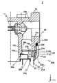
- FIG. 2 is a cross-sectional view schematically showing the filter device 1 and is a partially enlarged view.
- FIG. 3 is a sectional view schematically showing the filter element assembly 20. In FIGS. 1 to 3, some of the hatching showing the cross section is omitted.
- the filter device 1 mainly includes a head 10 and a filter element assembly 20.
- the head 10 is a substantially bottomed cylindrical member and is made of metal.
- the head 10 has an inlet and an outlet. The details of the head 10 will be described below with reference to FIG.
- a substantially cylindrical mounting portion 10a is formed on the side surface of the head 10 so as to protrude downward ( ⁇ z side) from the bottom surface.
- a male screw portion 10b is formed on the outer peripheral surface of the attachment portion 10a.
- the head 10 has a substantially cylindrical fitting cylinder 10c formed on the inner side of the mounting portion 10a so as to protrude downward ( ⁇ z side) from the bottom surface.
- the fitting cylinder 10c is inserted into the cylindrical portions 35a and 36a (detailed later) of the plates 35 and 36.
- the fitting cylinder 10c is formed with a flat surface 10d in contact with the filter element 30 on the outer periphery.
- the head 10 is formed with an inflow portion 10e for allowing the hydraulic oil to flow into the filter device 1 and an outflow portion 10f for allowing the hydraulic oil to flow out of the filter device 1.
- a valve 11 is provided on the wall surface of the bottom surface of the head 10 between the inflow portion 10e and the outflow portion 10f.
- the valve 11 opens and closes according to the difference between the pressure inside the inflow portion 10e and the pressure inside the outflow portion 10f. Since the well-known technique can be used for the valve 11, detailed description is omitted.
- the filter element assembly 20 mainly includes a case 21, a holding ring 25, and a filter element 30.
- the filter element assembly 20 will be described with reference to FIG.
- the case 21 is a substantially bottomed cylindrical member having one end substantially closed and the other end opened, and is made of metal.
- the case 21 includes a substantially bottomed cylindrical case body 22 and a substantially cylindrical cover 23.
- a filter element 30 is provided inside the case body 22.
- a spring 24 whose one end abuts on the bottom surface of the case body 22 and whose other end abuts on the filter element 30 is provided inside the case body 22.
- the case body 22 is provided with a cover 23 in the vicinity of the opening.
- the case main body 22 and the cover 23 are integrated by fitting the inner peripheral surface of the cover 23 to the outer peripheral surface of the case main body 22.
- An elastic member 41 (for example, an O-ring) 41 is provided between the outer peripheral surface of the case main body 22 and the inner peripheral surface of the cover 23, and the elastic member 41 seals between the case main body 22 and the cover 23. .
- a female screw portion 23 a is formed on the inner peripheral surface of the cover 23.
- the female thread portion 23a is formed near the open end of the cover 23 (that is, the case 21).
- a recess 23b is formed on the inner peripheral surface of the cover 23 (the surface on which the female screw portion 23a is formed).
- the concave portion 23b and the female screw portion 23a are adjacent to each other.
- the recess 23b is desirably provided near the tip of the cover 23 on the side not in contact with the case main body 22.
- An elastic member 45 (see FIGS. 1 and 2) is provided in the recess 23b.
- the elastic member 45 is a substantially disk-shaped member formed using a material capable of elastic deformation.
- a holding ring 25 is provided inside the case 21 (the case body 22 and the cover 23).
- the presser ring 25 is a substantially disk-shaped member having a hole formed in the center.
- a male screw portion 25 a is formed on the outer peripheral surface of the presser ring 25.
- the presser ring 25 is attached to the case 21, and the filter element assembly 20 is formed.
- An elastic member (for example, an O-ring) 42 is provided between the outer peripheral surface of the presser ring 25 and the inner peripheral surface of the case main body 22, and the case body 22 and the presser ring 25 are sealed by the elastic member 42. Is done.
- a recess 25 c is formed on the upper end surface 25 b of the presser ring 25.
- An elastic member (for example, an O-ring) 43 is provided in the recess 25c.
- the retaining ring 25 is attached to the case 21 after inserting the spring 24 and the filter element 30 into the case 21. Since the filter element is pressed upward (+ z direction) by the urging force of the spring 24, the filter element 30 comes into contact with the flat portion 25 d formed on the lower end surface of the presser ring 25.
- the filter element 30 mainly includes an inner cylinder 31, a filter medium 32, an inner cylinder 31, a filter medium 32, and plates 34, 35, and 36 provided at both ends of the filter medium 32.
- the inner cylinder 31 is a substantially hollow cylindrical member formed using a material having high corrosion resistance (in this embodiment, resin). A large number of holes 31 a through which hydraulic oil passes are formed on the entire surface of the inner cylinder 31.
- the filter medium 32 has a substantially hollow cylindrical shape having a thickness in the radial direction.
- the filter medium 32 is formed by folding a sheet-like filter paper using synthetic resin, paper, or the like, and connecting both ends of the folded filter paper into a cylindrical shape.
- the filter medium 32 is provided outside the inner cylinder 31.
- a plate 34 is provided at one end (lower end) of the inner cylinder 31 and the filter medium 32, and a plate 35 is provided at the other end (upper end).
- the plate 34 and the plate 35 are bottomed substantially cylindrical members, and are formed using a material having high corrosion resistance.
- the plate 34 has a recess 34a at the center.
- the spring 24 abuts on the ⁇ z side of the recess 34a.
- a plate 36 is provided on the upper (+ z) side of the plate 35.
- the plates 35 and 36 are respectively formed with cylindrical portions 35a and 36a having a substantially cylindrical shape at the center.
- a convex surface 36c is formed on the upper surface 36b of the plate 36 so as to surround the cylindrical portion 36a.
- the case 21 is attached to the head 10 by screwing the screw portion 23 a formed on the cover 23 into the male screw portion 10 b formed on the head 10.
- the elastic member 45 is provided in the concave portion 23b formed in the cover 23, when the case 21 is attached to the head 10, the elastic member 45 is deformed along the uneven shape of the external thread portion 10b. As a result, the elastic member 45 seals between the case 21 and the head 10.
- the fitting cylinder 10c When the case 21 is attached to the head 10, the fitting cylinder 10c is inserted into the cylindrical portions 35a and 36a of the plates 35 and 36, and the flat surface 10d presses the convex surface 36c in the -z direction. Thereby, the filter element 30 is positioned inside the case 21. Further, the space between the head 10 and the presser ring 25 (that is, the filter element assembly 20) is sealed by the elastic member 43 provided in the recess 25c.
- FIG. 1 The arrows in FIG. 1 indicate the flow of hydraulic oil inside the filter device 1.
- the hydraulic oil L1 to be filtered out of the hydraulic oil flows into the space S1 through the inflow portion 10e.
- the hydraulic oil L1 flowing into the space S1 flows into the space S2 between the case 21 and the filter element 30.
- the hydraulic oil L1 passes through the filter medium 32 and the inner cylinder 31 in order, and flows out into the space S3 that is the internal space of the inner cylinder 31.
- the hydraulic oil L1 is filtered by the filter medium 32.
- the filtered hydraulic oil L2 flowing out into the space S3 is discharged to the outside of the filter device 1 through the space S4 and the outflow portion 10f.
- the filter device 1 If the use of the filter device 1 is continued, dust adheres to the filter medium 32, and the pressure difference between the space S1 and the space S4 increases.
- the pressure difference between the space S1 and the space S4 exceeds a certain threshold value (the threshold value can be set to an arbitrary value)
- the valve 11 is opened and the hydraulic oil L1 is discharged into the space S4.
- the elastic member 45 is deformed along the concavo-convex shape of the external thread portion 10b, and the space between the external thread portion 10b and the cover 23 is sealed. Therefore, it is possible to prevent water and foreign matter from entering the male screw portion 10b and the female screw portion 23a (hereinafter referred to as a screwing portion).
- the elastic member 45 Even if the elastic member 45 is not provided, since the elastic member 42 is provided between the outer peripheral surface of the presser ring 25 and the inner peripheral surface of the case main body 22, the inside of the case 21. Water and foreign matter do not enter, and oil does not leak to the outside of the case 21. However, if water enters the threaded portion, the region outside the elastic member 42 (see the two-dot chain line in FIG. 2) may rust. When rust is generated, the surface of the inner peripheral surface of the case body 22 and the outer peripheral surface of the presser ring 25 is eroded and roughened, as well as the male screw portion 10b, the female screw portion 23a, and the male screw portion 25a.
- the pressure inside the case 21 is high. Therefore, if the region outside the elastic member 42 is rusted, the amount of deformation of the elastic member 42 is reduced when the elastic member 42 receives pressure and moves outward, reducing the sealing ability, and from the inside to the outside. Oil may leak. Further, if foreign matter is mixed in the screwing portion, the surface of the external thread portion 10b or the female screw portion 23a may be damaged when the screwing is removed.
- the female screw portion 23 a is formed on the inner peripheral surface of the cover 23 and the male screw portion 10 b is formed on the outer peripheral surface of the mounting portion 10 a, but the male screw portion is formed on the outer peripheral surface of the cover 23.
- the female thread portion may be formed on the inner peripheral surface of the attachment portion 10a.
- a concave portion for providing the elastic member may be formed on the outer peripheral surface of the cover 23 adjacent to the male screw portion.
- the elastic member 45 is provided in the recess 23b formed on the inner peripheral surface of the cover 23 to seal the screwed portion.
- the method for sealing the screwed portion is limited to this. Absent.
- the space between the front end surface of the case and the head is sealed with an elastic member.
- a filter device 2 according to a second embodiment of the present invention will be described. Since the difference between the filter device 1 and the filter device 2 is only the cover and the elastic member, hereinafter, the filter device 2 will be described with respect to the cover 23A and the elastic member 46, and the same parts as those in the first embodiment will be described. The same reference numerals are given and description thereof is omitted.
- FIG. 4 is a cross-sectional view showing an outline of the filter device 2, and is a partially enlarged view.
- the filter device 2 mainly includes a head 10 and a filter element assembly 20A.
- the filter element assembly 20A mainly includes a case 21A, a holding ring 25, and a filter element 30.
- the case 21A includes a case main body 22 and a substantially cylindrical cover 23A.
- the cover 23A and the cover 23 differ only in the position of the recess.
- the cover 23A is formed with a recess 23d so as to cut out a part of the front end surface 23c substantially orthogonal to the inner peripheral surface or outer peripheral surface of the cover 23A (that is, the case 21A).
- the elastic member 46 is provided in the recess 23d.
- the elastic member 46 is a substantially disk-shaped member formed using a material capable of elastic deformation.
- the case 21A When the case 21A is attached to the head 10 by screwing the screw portion 23a formed on the cover 23 into the male screw portion 10b formed on the head 10, and the inner peripheral portion of the elastic member 46 is the male screw portion 10b. Deforms along the irregular shape. As a result, the elastic member 46 seals between the inner peripheral surface of the case 21 and the outer peripheral surface of the head 10.
- the elastic member 46 is deformed in the thickness direction (z direction). As a result, the elastic member 46 seals between the front end surface 23 c of the case 21 and the head 10.
- the space between the case 21 and the head 10 is sealed in a plurality of directions, it is possible to reliably prevent water and foreign matter from being mixed into the screwing portion.
- the third embodiment of the present invention is a mode in which the space between the front end surface of the case and the head is sealed by an elastic member in addition to the screwed portion between the case and the head.
- a filter device 3 according to a third embodiment of the present invention will be described. Since the difference between the filter device 1 and the filter device 3 is only the cover and the elastic member, hereinafter, the filter device 3 will be described with respect to the cover 23B and the elastic member 47, and the same parts as those of the first embodiment will be described. The same reference numerals are given and description thereof is omitted.
- FIG. 5 is a cross-sectional view showing an outline of the filter device 3, and is a partially enlarged view.
- the filter device 2 mainly includes a head 10 and a filter element assembly 20B.
- the filter element assembly 20B mainly includes a case 21B, a holding ring 25, and a filter element 30.
- the case 21B includes a case body 22 and a substantially cylindrical cover 23B.
- the cover 23B and the cover 23 differ only in the position of the recess.
- a recess 23e is formed in the cover 23B so as to cut out a part of the front end surface 23c substantially orthogonal to the inner peripheral surface or outer peripheral surface of the cover 23B (that is, the case 21B).
- the elastic member 47 is a substantially disk-shaped member formed using a material capable of elastic deformation.
- the elastic member 47 has a substantially U-shaped cross section, and is provided on the cover 23B so as to cover the distal end surface 23c and the recess 23e.
- the inner peripheral portion of the elastic member 47 is the male screw portion 10b. Deforms along the irregular shape. As a result, the elastic member 47 seals between the inner peripheral surface of the case 21 and the outer peripheral surface of the head 10.
- the elastic member 47 covers the space between the front end surface 23 c of the case 21 and the head 10. As a result, the elastic member 47 seals between the front end surface 23 c of the case 21 and the head 10.
- the space between the case 21 and the head 10 is sealed in a plurality of directions, it is possible to reliably prevent water and foreign matter from being mixed into the screwing portion. Further, since the elastic member 47 is provided on the cover 23B so as to cover the distal end surface 23c and the recess 23e, the elastic member 47 can be easily attached to the filter element assembly 20B, and the filter element assembly 20B can be easily attached to the head 10.
- “substantially” is a concept that includes not only a case where they are exactly the same but also errors and deformations that do not lose the identity.
- the “substantially cylindrical shape” is not limited to a strictly cylindrical shape.
- the case is not limited to strictly the center, but includes the case of the approximate center.
- “near” means including a region in a certain range (which can be arbitrarily determined) near a reference position. For example, in the case of the vicinity of the opening end, it is a concept indicating that the region in a certain range near the opening end may or may not include the opening end.
- Filter device 10 Head 10a: Mounting portion 10b: Male thread portion 10c: Fitting cylinder 10d: Plane 10e: Inflow portion 10f: Outflow portion 11: Valves 20, 20A, 20B: Filter element assembly 21 , 21A, 21B: Case 22: Case main body 23, 23A, 23B: Cover 23a: Female thread 23b, 23d, 23e: Recess 23c: Tip surface 24: Spring 25: Presser ring 25a: Male thread 25b: Upper end 25c : Concave portion 25d: plane portion 30: filter element 31: inner cylinder 31a: hole 32: filter medium 34, 35, 36: plate 34a: concave portion 35a, 36a: cylindrical portion 36b: upper surface 36c: convex surfaces 41, 42, 43, 44 , 45, 46, 47: elastic member
Landscapes
- Chemical & Material Sciences (AREA)
- Chemical Kinetics & Catalysis (AREA)
- Filtration Of Liquid (AREA)
- Lubrication Details And Ventilation Of Internal Combustion Engines (AREA)
Priority Applications (4)
| Application Number | Priority Date | Filing Date | Title |
|---|---|---|---|
| CN201780055099.7A CN109715262A (zh) | 2016-09-09 | 2017-08-14 | 过滤装置 |
| EP17848524.9A EP3511066A4 (en) | 2016-09-09 | 2017-08-14 | FILTER DEVICE |
| KR1020197006696A KR20190043553A (ko) | 2016-09-09 | 2017-08-14 | 필터 장치 |
| US16/291,778 US20190193009A1 (en) | 2016-09-09 | 2019-03-04 | Filter device |
Applications Claiming Priority (2)
| Application Number | Priority Date | Filing Date | Title |
|---|---|---|---|
| JP2016-176138 | 2016-09-09 | ||
| JP2016176138A JP6814000B2 (ja) | 2016-09-09 | 2016-09-09 | フィルタ装置 |
Related Child Applications (1)
| Application Number | Title | Priority Date | Filing Date |
|---|---|---|---|
| US16/291,778 Continuation US20190193009A1 (en) | 2016-09-09 | 2019-03-04 | Filter device |
Publications (1)
| Publication Number | Publication Date |
|---|---|
| WO2018047580A1 true WO2018047580A1 (ja) | 2018-03-15 |
Family
ID=61561977
Family Applications (1)
| Application Number | Title | Priority Date | Filing Date |
|---|---|---|---|
| PCT/JP2017/029256 Ceased WO2018047580A1 (ja) | 2016-09-09 | 2017-08-14 | フィルタ装置 |
Country Status (6)
| Country | Link |
|---|---|
| US (1) | US20190193009A1 (enExample) |
| EP (1) | EP3511066A4 (enExample) |
| JP (1) | JP6814000B2 (enExample) |
| KR (1) | KR20190043553A (enExample) |
| CN (1) | CN109715262A (enExample) |
| WO (1) | WO2018047580A1 (enExample) |
Families Citing this family (1)
| Publication number | Priority date | Publication date | Assignee | Title |
|---|---|---|---|---|
| TWI804820B (zh) * | 2021-02-26 | 2023-06-11 | 沛毅工業股份有限公司 | 濾水器濾殼 |
Citations (6)
| Publication number | Priority date | Publication date | Assignee | Title |
|---|---|---|---|---|
| US5066391A (en) * | 1990-08-22 | 1991-11-19 | Faria Manuel S | Reusable liquid filter assembly |
| JP2000503590A (ja) * | 1996-05-02 | 2000-03-28 | アルコ・インダストリーズ・インク | 転造ネジフィルタボウル |
| JP4033739B2 (ja) * | 2002-08-27 | 2008-01-16 | ヤマシンフィルタ株式会社 | フィルタ装置 |
| JP2009085035A (ja) * | 2007-09-27 | 2009-04-23 | Toyota Boshoku Corp | 2部材の締結構造及びそれを用いた流体フィルタ |
| JP2010540218A (ja) * | 2007-09-27 | 2010-12-24 | ハイダック フィルターテヒニク ゲゼルシャフト ミット ベシュレンクテル ハフツング | フィルタ装置とフィルタエレメント |
| JP2011062658A (ja) * | 2009-09-18 | 2011-03-31 | Wako Filter Technology Kk | スピンオンフィルタおよびそのフィルタ用エレメント組立体 |
Family Cites Families (8)
| Publication number | Priority date | Publication date | Assignee | Title |
|---|---|---|---|---|
| US4320005A (en) * | 1979-03-21 | 1982-03-16 | Degraffenreid Howard T | Coalescer or filter end cap |
| JP2859475B2 (ja) * | 1991-10-07 | 1999-02-17 | 和興産業株式会社 | スピンオンフィルターおよびそのフィルター用エレメント組立体 |
| US6554140B2 (en) * | 2000-12-19 | 2003-04-29 | Fleetguard, Inc. | Spin-on filter assembly |
| EP1938882B1 (en) * | 2005-10-13 | 2011-02-23 | Yamashin-Filter Corp. | Filtration device |
| CN101370563B (zh) * | 2005-11-15 | 2013-08-28 | 唐纳森公司 | 液体过滤器结构和过滤器部件 |
| KR101559263B1 (ko) * | 2011-10-17 | 2015-10-08 | 미츠비시 마테리알 가부시키가이샤 | 헤드 교환식 절삭 공구용 홀더 및 헤드 교환식 절삭 공구 |
| US9764263B2 (en) * | 2012-03-01 | 2017-09-19 | Caterpillar Inc. | Filter element |
| US20150090651A1 (en) * | 2013-10-02 | 2015-04-02 | Stanadyne Corporation | Fuel Filter Cartridge and Method of Use Thereof |
-
2016
- 2016-09-09 JP JP2016176138A patent/JP6814000B2/ja active Active
-
2017
- 2017-08-14 KR KR1020197006696A patent/KR20190043553A/ko not_active Withdrawn
- 2017-08-14 WO PCT/JP2017/029256 patent/WO2018047580A1/ja not_active Ceased
- 2017-08-14 EP EP17848524.9A patent/EP3511066A4/en not_active Withdrawn
- 2017-08-14 CN CN201780055099.7A patent/CN109715262A/zh active Pending
-
2019
- 2019-03-04 US US16/291,778 patent/US20190193009A1/en not_active Abandoned
Patent Citations (6)
| Publication number | Priority date | Publication date | Assignee | Title |
|---|---|---|---|---|
| US5066391A (en) * | 1990-08-22 | 1991-11-19 | Faria Manuel S | Reusable liquid filter assembly |
| JP2000503590A (ja) * | 1996-05-02 | 2000-03-28 | アルコ・インダストリーズ・インク | 転造ネジフィルタボウル |
| JP4033739B2 (ja) * | 2002-08-27 | 2008-01-16 | ヤマシンフィルタ株式会社 | フィルタ装置 |
| JP2009085035A (ja) * | 2007-09-27 | 2009-04-23 | Toyota Boshoku Corp | 2部材の締結構造及びそれを用いた流体フィルタ |
| JP2010540218A (ja) * | 2007-09-27 | 2010-12-24 | ハイダック フィルターテヒニク ゲゼルシャフト ミット ベシュレンクテル ハフツング | フィルタ装置とフィルタエレメント |
| JP2011062658A (ja) * | 2009-09-18 | 2011-03-31 | Wako Filter Technology Kk | スピンオンフィルタおよびそのフィルタ用エレメント組立体 |
Non-Patent Citations (1)
| Title |
|---|
| See also references of EP3511066A4 * |
Also Published As
| Publication number | Publication date |
|---|---|
| JP6814000B2 (ja) | 2021-01-13 |
| CN109715262A (zh) | 2019-05-03 |
| KR20190043553A (ko) | 2019-04-26 |
| JP2018038982A (ja) | 2018-03-15 |
| EP3511066A1 (en) | 2019-07-17 |
| EP3511066A4 (en) | 2019-09-04 |
| US20190193009A1 (en) | 2019-06-27 |
Similar Documents
| Publication | Publication Date | Title |
|---|---|---|
| CN101854996B (zh) | 用于液体过滤器的过滤器元件以及液体过滤器 | |
| JP5340867B2 (ja) | スピンオンフィルタおよびそのフィルタ用エレメント組立体 | |
| BR112014005384B1 (pt) | recipiente de filtração | |
| CN105916566A (zh) | 过滤器元件 | |
| JP6232224B2 (ja) | ダイヤフラム弁 | |
| US11602705B2 (en) | Filtration device | |
| US11712643B2 (en) | Filtration device | |
| CN101553432A (zh) | 滤芯组件 | |
| CN114173901B (zh) | 具有阀启动特征的滤筒 | |
| WO2018047580A1 (ja) | フィルタ装置 | |
| JP4830929B2 (ja) | オイルフィルタ | |
| JP6450781B2 (ja) | ブレーキフルード貯蔵部 | |
| JP4924465B2 (ja) | ドレン機構及びこれを備える流体フィルタ | |
| JP2017042754A (ja) | フィルタ装置 | |
| US20150343338A1 (en) | Filter element and filtering device | |
| CN113226515A (zh) | 集成多功能端盖密封构件 | |
| JP6839520B2 (ja) | フィルタ装置 | |
| US10058801B2 (en) | Filter with diverse shaped and dimensioned protrusions formed on an end plate of its cylindrically shaped filter material | |
| CN206837596U (zh) | 封水组件、滤芯、水路板组件以及净水器 | |
| JP2018084180A (ja) | オイルフィルタ | |
| CN107921336B (zh) | 过滤器端口密封件 | |
| JP2008289987A (ja) | 流体フィルタのドレン機構 | |
| JP6756592B2 (ja) | 逆止弁 | |
| JP4579756B2 (ja) | 定流量弁及び定流量継手 | |
| JP7050385B2 (ja) | 減圧弁 |
Legal Events
| Date | Code | Title | Description |
|---|---|---|---|
| 121 | Ep: the epo has been informed by wipo that ep was designated in this application |
Ref document number: 17848524 Country of ref document: EP Kind code of ref document: A1 |
|
| ENP | Entry into the national phase |
Ref document number: 20197006696 Country of ref document: KR Kind code of ref document: A |
|
| NENP | Non-entry into the national phase |
Ref country code: DE |
|
| ENP | Entry into the national phase |
Ref document number: 2017848524 Country of ref document: EP Effective date: 20190409 |