WO2018047580A1 - Filter device - Google Patents
Filter device Download PDFInfo
- Publication number
- WO2018047580A1 WO2018047580A1 PCT/JP2017/029256 JP2017029256W WO2018047580A1 WO 2018047580 A1 WO2018047580 A1 WO 2018047580A1 JP 2017029256 W JP2017029256 W JP 2017029256W WO 2018047580 A1 WO2018047580 A1 WO 2018047580A1
- Authority
- WO
- WIPO (PCT)
- Prior art keywords
- case
- head
- elastic member
- screw portion
- filter element
- Prior art date
Links
- 230000002093 peripheral effect Effects 0.000 claims description 38
- 239000000463 material Substances 0.000 claims description 9
- 230000005489 elastic deformation Effects 0.000 claims description 5
- XLYOFNOQVPJJNP-UHFFFAOYSA-N water Substances O XLYOFNOQVPJJNP-UHFFFAOYSA-N 0.000 abstract description 13
- 230000001788 irregular Effects 0.000 abstract description 3
- 239000012535 impurity Substances 0.000 abstract 1
- 239000010720 hydraulic oil Substances 0.000 description 11
- 239000003921 oil Substances 0.000 description 3
- 238000005260 corrosion Methods 0.000 description 2
- 230000007797 corrosion Effects 0.000 description 2
- JEIPFZHSYJVQDO-UHFFFAOYSA-N iron(III) oxide Inorganic materials O=[Fe]O[Fe]=O JEIPFZHSYJVQDO-UHFFFAOYSA-N 0.000 description 2
- 239000002184 metal Substances 0.000 description 2
- 238000000034 method Methods 0.000 description 2
- 238000007789 sealing Methods 0.000 description 2
- 239000000428 dust Substances 0.000 description 1
- 238000001914 filtration Methods 0.000 description 1
- 230000012447 hatching Effects 0.000 description 1
- 229920005989 resin Polymers 0.000 description 1
- 239000011347 resin Substances 0.000 description 1
- 229920003002 synthetic resin Polymers 0.000 description 1
- 239000000057 synthetic resin Substances 0.000 description 1
Images


Classifications
-
- B—PERFORMING OPERATIONS; TRANSPORTING
- B01—PHYSICAL OR CHEMICAL PROCESSES OR APPARATUS IN GENERAL
- B01D—SEPARATION
- B01D35/00—Filtering devices having features not specifically covered by groups B01D24/00 - B01D33/00, or for applications not specifically covered by groups B01D24/00 - B01D33/00; Auxiliary devices for filtration; Filter housing constructions
- B01D35/14—Safety devices specially adapted for filtration; Devices for indicating clogging
- B01D35/147—Bypass or safety valves
-
- B—PERFORMING OPERATIONS; TRANSPORTING
- B01—PHYSICAL OR CHEMICAL PROCESSES OR APPARATUS IN GENERAL
- B01D—SEPARATION
- B01D29/00—Filters with filtering elements stationary during filtration, e.g. pressure or suction filters, not covered by groups B01D24/00 - B01D27/00; Filtering elements therefor
- B01D29/11—Filters with filtering elements stationary during filtration, e.g. pressure or suction filters, not covered by groups B01D24/00 - B01D27/00; Filtering elements therefor with bag, cage, hose, tube, sleeve or like filtering elements
-
- B—PERFORMING OPERATIONS; TRANSPORTING
- B01—PHYSICAL OR CHEMICAL PROCESSES OR APPARATUS IN GENERAL
- B01D—SEPARATION
- B01D35/00—Filtering devices having features not specifically covered by groups B01D24/00 - B01D33/00, or for applications not specifically covered by groups B01D24/00 - B01D33/00; Auxiliary devices for filtration; Filter housing constructions
- B01D35/30—Filter housing constructions
-
- B—PERFORMING OPERATIONS; TRANSPORTING
- B01—PHYSICAL OR CHEMICAL PROCESSES OR APPARATUS IN GENERAL
- B01D—SEPARATION
- B01D29/00—Filters with filtering elements stationary during filtration, e.g. pressure or suction filters, not covered by groups B01D24/00 - B01D27/00; Filtering elements therefor
- B01D29/01—Filters with filtering elements stationary during filtration, e.g. pressure or suction filters, not covered by groups B01D24/00 - B01D27/00; Filtering elements therefor with flat filtering elements
- B01D29/05—Filters with filtering elements stationary during filtration, e.g. pressure or suction filters, not covered by groups B01D24/00 - B01D27/00; Filtering elements therefor with flat filtering elements supported
- B01D29/07—Filters with filtering elements stationary during filtration, e.g. pressure or suction filters, not covered by groups B01D24/00 - B01D27/00; Filtering elements therefor with flat filtering elements supported with corrugated, folded or wound filtering sheets
-
- B—PERFORMING OPERATIONS; TRANSPORTING
- B01—PHYSICAL OR CHEMICAL PROCESSES OR APPARATUS IN GENERAL
- B01D—SEPARATION
- B01D29/00—Filters with filtering elements stationary during filtration, e.g. pressure or suction filters, not covered by groups B01D24/00 - B01D27/00; Filtering elements therefor
- B01D29/11—Filters with filtering elements stationary during filtration, e.g. pressure or suction filters, not covered by groups B01D24/00 - B01D27/00; Filtering elements therefor with bag, cage, hose, tube, sleeve or like filtering elements
- B01D29/13—Supported filter elements
- B01D29/15—Supported filter elements arranged for inward flow filtration
- B01D29/21—Supported filter elements arranged for inward flow filtration with corrugated, folded or wound sheets
-
- B—PERFORMING OPERATIONS; TRANSPORTING
- B01—PHYSICAL OR CHEMICAL PROCESSES OR APPARATUS IN GENERAL
- B01D—SEPARATION
- B01D35/00—Filtering devices having features not specifically covered by groups B01D24/00 - B01D33/00, or for applications not specifically covered by groups B01D24/00 - B01D33/00; Auxiliary devices for filtration; Filter housing constructions
- B01D35/02—Filters adapted for location in special places, e.g. pipe-lines, pumps, stop-cocks
-
- B—PERFORMING OPERATIONS; TRANSPORTING
- B01—PHYSICAL OR CHEMICAL PROCESSES OR APPARATUS IN GENERAL
- B01D—SEPARATION
- B01D2201/00—Details relating to filtering apparatus
- B01D2201/29—Filter cartridge constructions
- B01D2201/291—End caps
- B01D2201/295—End caps with projections extending in a radial outward direction, e.g. for use as a guide, spacing means
-
- B—PERFORMING OPERATIONS; TRANSPORTING
- B01—PHYSICAL OR CHEMICAL PROCESSES OR APPARATUS IN GENERAL
- B01D—SEPARATION
- B01D2201/00—Details relating to filtering apparatus
- B01D2201/30—Filter housing constructions
- B01D2201/301—Details of removable closures, lids, caps, filter heads
- B01D2201/302—Details of removable closures, lids, caps, filter heads having inlet or outlet ports
-
- B—PERFORMING OPERATIONS; TRANSPORTING
- B01—PHYSICAL OR CHEMICAL PROCESSES OR APPARATUS IN GENERAL
- B01D—SEPARATION
- B01D2201/00—Details relating to filtering apparatus
- B01D2201/30—Filter housing constructions
- B01D2201/301—Details of removable closures, lids, caps, filter heads
- B01D2201/304—Seals or gaskets
-
- B—PERFORMING OPERATIONS; TRANSPORTING
- B01—PHYSICAL OR CHEMICAL PROCESSES OR APPARATUS IN GENERAL
- B01D—SEPARATION
- B01D2201/00—Details relating to filtering apparatus
- B01D2201/34—Seals or gaskets for filtering elements
- B01D2201/342—Axial sealings
-
- B—PERFORMING OPERATIONS; TRANSPORTING
- B01—PHYSICAL OR CHEMICAL PROCESSES OR APPARATUS IN GENERAL
- B01D—SEPARATION
- B01D2201/00—Details relating to filtering apparatus
- B01D2201/34—Seals or gaskets for filtering elements
- B01D2201/347—Radial sealings
-
- B—PERFORMING OPERATIONS; TRANSPORTING
- B01—PHYSICAL OR CHEMICAL PROCESSES OR APPARATUS IN GENERAL
- B01D—SEPARATION
- B01D2201/00—Details relating to filtering apparatus
- B01D2201/40—Special measures for connecting different parts of the filter
- B01D2201/4092—Threaded sections, e.g. screw
Definitions
- the present invention relates to a filter device.
- Patent Document 1 discloses a filter device in which a filter cartridge containing a filter element in a case is detachably attached to a head having an inlet and an outlet.
- the filter cartridge is detachably attached to the head via a nut provided on the outer periphery of the case.
- This invention is made in view of such a situation, and it aims at providing the filter apparatus which can prevent water and a foreign material from entering into a screwing part.
- a filter device is formed on, for example, a head having an inlet and an outlet, a substantially bottomed cylindrical case, and an inner peripheral surface or an outer peripheral surface of the case.
- a filter element assembly having a first threaded portion, the first threaded portion formed near the opening end of the case, and a filter element provided inside the case, and elastic deformation is possible
- a substantially disk-shaped elastic member formed using a material, wherein the head is formed with a second screw portion that is screwed with the first screw portion, and the case includes the first screw portion.
- a concave portion is formed adjacent to the first screw portion on the surface on which the screw portion is formed, and the elastic member is provided in the concave portion, and the first screw portion, the second screw portion, And the filter element assembly Together attached to the head, wherein the elastic member to seal between the second threaded section the head and the case is deformed along the uneven shape of.
- the filter element assembly when the first screw part formed near the opening end of the case and the second screw part formed on the head are screwed together, the filter element assembly is attached to the head. While being attached, the elastic member provided on the surface of the case where the first screw portion is formed is deformed along the uneven shape of the second screw portion. Thereby, between a case and a head can be sealed and it can prevent that a water and a foreign material enter into a screwing part (a 1st screw part and a 2nd screw part).
- the recess is formed so as to cut out a part of the inner peripheral surface of the case or a front end surface substantially perpendicular to the outer peripheral surface, and the elastic member is attached to the head by the filter element assembly. If it is done, you may seal between the said front end surface and the said head. Thereby, between the case and the head can be sealed in a plurality of directions, and it is possible to reliably prevent water and foreign matter from entering the screwed portion from being mixed into the screwed portion.
- the elastic member may have a substantially U-shaped cross section, and may be provided in the case so as to cover the tip surface. Thereby, between the case and the head can be sealed in a plurality of directions, and it is possible to reliably prevent water and foreign matter from entering the screwed portion from being mixed into the screwed portion. Further, since the elastic member is provided in the case so as to cover the front end surface, the elastic member can be easily attached to the filter element assembly, and the filter element assembly can be easily attached to the head.
- FIG. 2 is a cross-sectional view showing an outline of the filter device 1 and is a partially enlarged view.
- 2 is a cross-sectional view showing an outline of a filter element assembly 20.
- FIG. 3 is a cross-sectional view showing an outline of the filter device 2 and is a partially enlarged view.
- FIG. 3 is a cross-sectional view showing an outline of the filter device 3 and is a partially enlarged view.
- FIG. 1 is a sectional view schematically showing a filter device 1 according to the first embodiment of the present invention.
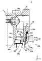
- FIG. 2 is a cross-sectional view schematically showing the filter device 1 and is a partially enlarged view.
- FIG. 3 is a sectional view schematically showing the filter element assembly 20. In FIGS. 1 to 3, some of the hatching showing the cross section is omitted.
- the filter device 1 mainly includes a head 10 and a filter element assembly 20.
- the head 10 is a substantially bottomed cylindrical member and is made of metal.
- the head 10 has an inlet and an outlet. The details of the head 10 will be described below with reference to FIG.
- a substantially cylindrical mounting portion 10a is formed on the side surface of the head 10 so as to protrude downward ( ⁇ z side) from the bottom surface.
- a male screw portion 10b is formed on the outer peripheral surface of the attachment portion 10a.
- the head 10 has a substantially cylindrical fitting cylinder 10c formed on the inner side of the mounting portion 10a so as to protrude downward ( ⁇ z side) from the bottom surface.
- the fitting cylinder 10c is inserted into the cylindrical portions 35a and 36a (detailed later) of the plates 35 and 36.
- the fitting cylinder 10c is formed with a flat surface 10d in contact with the filter element 30 on the outer periphery.
- the head 10 is formed with an inflow portion 10e for allowing the hydraulic oil to flow into the filter device 1 and an outflow portion 10f for allowing the hydraulic oil to flow out of the filter device 1.
- a valve 11 is provided on the wall surface of the bottom surface of the head 10 between the inflow portion 10e and the outflow portion 10f.
- the valve 11 opens and closes according to the difference between the pressure inside the inflow portion 10e and the pressure inside the outflow portion 10f. Since the well-known technique can be used for the valve 11, detailed description is omitted.
- the filter element assembly 20 mainly includes a case 21, a holding ring 25, and a filter element 30.
- the filter element assembly 20 will be described with reference to FIG.
- the case 21 is a substantially bottomed cylindrical member having one end substantially closed and the other end opened, and is made of metal.
- the case 21 includes a substantially bottomed cylindrical case body 22 and a substantially cylindrical cover 23.
- a filter element 30 is provided inside the case body 22.
- a spring 24 whose one end abuts on the bottom surface of the case body 22 and whose other end abuts on the filter element 30 is provided inside the case body 22.
- the case body 22 is provided with a cover 23 in the vicinity of the opening.
- the case main body 22 and the cover 23 are integrated by fitting the inner peripheral surface of the cover 23 to the outer peripheral surface of the case main body 22.
- An elastic member 41 (for example, an O-ring) 41 is provided between the outer peripheral surface of the case main body 22 and the inner peripheral surface of the cover 23, and the elastic member 41 seals between the case main body 22 and the cover 23. .
- a female screw portion 23 a is formed on the inner peripheral surface of the cover 23.
- the female thread portion 23a is formed near the open end of the cover 23 (that is, the case 21).
- a recess 23b is formed on the inner peripheral surface of the cover 23 (the surface on which the female screw portion 23a is formed).
- the concave portion 23b and the female screw portion 23a are adjacent to each other.
- the recess 23b is desirably provided near the tip of the cover 23 on the side not in contact with the case main body 22.
- An elastic member 45 (see FIGS. 1 and 2) is provided in the recess 23b.
- the elastic member 45 is a substantially disk-shaped member formed using a material capable of elastic deformation.
- a holding ring 25 is provided inside the case 21 (the case body 22 and the cover 23).
- the presser ring 25 is a substantially disk-shaped member having a hole formed in the center.
- a male screw portion 25 a is formed on the outer peripheral surface of the presser ring 25.
- the presser ring 25 is attached to the case 21, and the filter element assembly 20 is formed.
- An elastic member (for example, an O-ring) 42 is provided between the outer peripheral surface of the presser ring 25 and the inner peripheral surface of the case main body 22, and the case body 22 and the presser ring 25 are sealed by the elastic member 42. Is done.
- a recess 25 c is formed on the upper end surface 25 b of the presser ring 25.
- An elastic member (for example, an O-ring) 43 is provided in the recess 25c.
- the retaining ring 25 is attached to the case 21 after inserting the spring 24 and the filter element 30 into the case 21. Since the filter element is pressed upward (+ z direction) by the urging force of the spring 24, the filter element 30 comes into contact with the flat portion 25 d formed on the lower end surface of the presser ring 25.
- the filter element 30 mainly includes an inner cylinder 31, a filter medium 32, an inner cylinder 31, a filter medium 32, and plates 34, 35, and 36 provided at both ends of the filter medium 32.
- the inner cylinder 31 is a substantially hollow cylindrical member formed using a material having high corrosion resistance (in this embodiment, resin). A large number of holes 31 a through which hydraulic oil passes are formed on the entire surface of the inner cylinder 31.
- the filter medium 32 has a substantially hollow cylindrical shape having a thickness in the radial direction.
- the filter medium 32 is formed by folding a sheet-like filter paper using synthetic resin, paper, or the like, and connecting both ends of the folded filter paper into a cylindrical shape.
- the filter medium 32 is provided outside the inner cylinder 31.
- a plate 34 is provided at one end (lower end) of the inner cylinder 31 and the filter medium 32, and a plate 35 is provided at the other end (upper end).
- the plate 34 and the plate 35 are bottomed substantially cylindrical members, and are formed using a material having high corrosion resistance.
- the plate 34 has a recess 34a at the center.
- the spring 24 abuts on the ⁇ z side of the recess 34a.
- a plate 36 is provided on the upper (+ z) side of the plate 35.
- the plates 35 and 36 are respectively formed with cylindrical portions 35a and 36a having a substantially cylindrical shape at the center.
- a convex surface 36c is formed on the upper surface 36b of the plate 36 so as to surround the cylindrical portion 36a.
- the case 21 is attached to the head 10 by screwing the screw portion 23 a formed on the cover 23 into the male screw portion 10 b formed on the head 10.
- the elastic member 45 is provided in the concave portion 23b formed in the cover 23, when the case 21 is attached to the head 10, the elastic member 45 is deformed along the uneven shape of the external thread portion 10b. As a result, the elastic member 45 seals between the case 21 and the head 10.
- the fitting cylinder 10c When the case 21 is attached to the head 10, the fitting cylinder 10c is inserted into the cylindrical portions 35a and 36a of the plates 35 and 36, and the flat surface 10d presses the convex surface 36c in the -z direction. Thereby, the filter element 30 is positioned inside the case 21. Further, the space between the head 10 and the presser ring 25 (that is, the filter element assembly 20) is sealed by the elastic member 43 provided in the recess 25c.
- FIG. 1 The arrows in FIG. 1 indicate the flow of hydraulic oil inside the filter device 1.
- the hydraulic oil L1 to be filtered out of the hydraulic oil flows into the space S1 through the inflow portion 10e.
- the hydraulic oil L1 flowing into the space S1 flows into the space S2 between the case 21 and the filter element 30.
- the hydraulic oil L1 passes through the filter medium 32 and the inner cylinder 31 in order, and flows out into the space S3 that is the internal space of the inner cylinder 31.
- the hydraulic oil L1 is filtered by the filter medium 32.
- the filtered hydraulic oil L2 flowing out into the space S3 is discharged to the outside of the filter device 1 through the space S4 and the outflow portion 10f.
- the filter device 1 If the use of the filter device 1 is continued, dust adheres to the filter medium 32, and the pressure difference between the space S1 and the space S4 increases.
- the pressure difference between the space S1 and the space S4 exceeds a certain threshold value (the threshold value can be set to an arbitrary value)
- the valve 11 is opened and the hydraulic oil L1 is discharged into the space S4.
- the elastic member 45 is deformed along the concavo-convex shape of the external thread portion 10b, and the space between the external thread portion 10b and the cover 23 is sealed. Therefore, it is possible to prevent water and foreign matter from entering the male screw portion 10b and the female screw portion 23a (hereinafter referred to as a screwing portion).
- the elastic member 45 Even if the elastic member 45 is not provided, since the elastic member 42 is provided between the outer peripheral surface of the presser ring 25 and the inner peripheral surface of the case main body 22, the inside of the case 21. Water and foreign matter do not enter, and oil does not leak to the outside of the case 21. However, if water enters the threaded portion, the region outside the elastic member 42 (see the two-dot chain line in FIG. 2) may rust. When rust is generated, the surface of the inner peripheral surface of the case body 22 and the outer peripheral surface of the presser ring 25 is eroded and roughened, as well as the male screw portion 10b, the female screw portion 23a, and the male screw portion 25a.
- the pressure inside the case 21 is high. Therefore, if the region outside the elastic member 42 is rusted, the amount of deformation of the elastic member 42 is reduced when the elastic member 42 receives pressure and moves outward, reducing the sealing ability, and from the inside to the outside. Oil may leak. Further, if foreign matter is mixed in the screwing portion, the surface of the external thread portion 10b or the female screw portion 23a may be damaged when the screwing is removed.
- the female screw portion 23 a is formed on the inner peripheral surface of the cover 23 and the male screw portion 10 b is formed on the outer peripheral surface of the mounting portion 10 a, but the male screw portion is formed on the outer peripheral surface of the cover 23.
- the female thread portion may be formed on the inner peripheral surface of the attachment portion 10a.
- a concave portion for providing the elastic member may be formed on the outer peripheral surface of the cover 23 adjacent to the male screw portion.
- the elastic member 45 is provided in the recess 23b formed on the inner peripheral surface of the cover 23 to seal the screwed portion.
- the method for sealing the screwed portion is limited to this. Absent.
- the space between the front end surface of the case and the head is sealed with an elastic member.
- a filter device 2 according to a second embodiment of the present invention will be described. Since the difference between the filter device 1 and the filter device 2 is only the cover and the elastic member, hereinafter, the filter device 2 will be described with respect to the cover 23A and the elastic member 46, and the same parts as those in the first embodiment will be described. The same reference numerals are given and description thereof is omitted.
- FIG. 4 is a cross-sectional view showing an outline of the filter device 2, and is a partially enlarged view.
- the filter device 2 mainly includes a head 10 and a filter element assembly 20A.
- the filter element assembly 20A mainly includes a case 21A, a holding ring 25, and a filter element 30.
- the case 21A includes a case main body 22 and a substantially cylindrical cover 23A.
- the cover 23A and the cover 23 differ only in the position of the recess.
- the cover 23A is formed with a recess 23d so as to cut out a part of the front end surface 23c substantially orthogonal to the inner peripheral surface or outer peripheral surface of the cover 23A (that is, the case 21A).
- the elastic member 46 is provided in the recess 23d.
- the elastic member 46 is a substantially disk-shaped member formed using a material capable of elastic deformation.
- the case 21A When the case 21A is attached to the head 10 by screwing the screw portion 23a formed on the cover 23 into the male screw portion 10b formed on the head 10, and the inner peripheral portion of the elastic member 46 is the male screw portion 10b. Deforms along the irregular shape. As a result, the elastic member 46 seals between the inner peripheral surface of the case 21 and the outer peripheral surface of the head 10.
- the elastic member 46 is deformed in the thickness direction (z direction). As a result, the elastic member 46 seals between the front end surface 23 c of the case 21 and the head 10.
- the space between the case 21 and the head 10 is sealed in a plurality of directions, it is possible to reliably prevent water and foreign matter from being mixed into the screwing portion.
- the third embodiment of the present invention is a mode in which the space between the front end surface of the case and the head is sealed by an elastic member in addition to the screwed portion between the case and the head.
- a filter device 3 according to a third embodiment of the present invention will be described. Since the difference between the filter device 1 and the filter device 3 is only the cover and the elastic member, hereinafter, the filter device 3 will be described with respect to the cover 23B and the elastic member 47, and the same parts as those of the first embodiment will be described. The same reference numerals are given and description thereof is omitted.
- FIG. 5 is a cross-sectional view showing an outline of the filter device 3, and is a partially enlarged view.
- the filter device 2 mainly includes a head 10 and a filter element assembly 20B.
- the filter element assembly 20B mainly includes a case 21B, a holding ring 25, and a filter element 30.
- the case 21B includes a case body 22 and a substantially cylindrical cover 23B.
- the cover 23B and the cover 23 differ only in the position of the recess.
- a recess 23e is formed in the cover 23B so as to cut out a part of the front end surface 23c substantially orthogonal to the inner peripheral surface or outer peripheral surface of the cover 23B (that is, the case 21B).
- the elastic member 47 is a substantially disk-shaped member formed using a material capable of elastic deformation.
- the elastic member 47 has a substantially U-shaped cross section, and is provided on the cover 23B so as to cover the distal end surface 23c and the recess 23e.
- the inner peripheral portion of the elastic member 47 is the male screw portion 10b. Deforms along the irregular shape. As a result, the elastic member 47 seals between the inner peripheral surface of the case 21 and the outer peripheral surface of the head 10.
- the elastic member 47 covers the space between the front end surface 23 c of the case 21 and the head 10. As a result, the elastic member 47 seals between the front end surface 23 c of the case 21 and the head 10.
- the space between the case 21 and the head 10 is sealed in a plurality of directions, it is possible to reliably prevent water and foreign matter from being mixed into the screwing portion. Further, since the elastic member 47 is provided on the cover 23B so as to cover the distal end surface 23c and the recess 23e, the elastic member 47 can be easily attached to the filter element assembly 20B, and the filter element assembly 20B can be easily attached to the head 10.
- “substantially” is a concept that includes not only a case where they are exactly the same but also errors and deformations that do not lose the identity.
- the “substantially cylindrical shape” is not limited to a strictly cylindrical shape.
- the case is not limited to strictly the center, but includes the case of the approximate center.
- “near” means including a region in a certain range (which can be arbitrarily determined) near a reference position. For example, in the case of the vicinity of the opening end, it is a concept indicating that the region in a certain range near the opening end may or may not include the opening end.
- Filter device 10 Head 10a: Mounting portion 10b: Male thread portion 10c: Fitting cylinder 10d: Plane 10e: Inflow portion 10f: Outflow portion 11: Valves 20, 20A, 20B: Filter element assembly 21 , 21A, 21B: Case 22: Case main body 23, 23A, 23B: Cover 23a: Female thread 23b, 23d, 23e: Recess 23c: Tip surface 24: Spring 25: Presser ring 25a: Male thread 25b: Upper end 25c : Concave portion 25d: plane portion 30: filter element 31: inner cylinder 31a: hole 32: filter medium 34, 35, 36: plate 34a: concave portion 35a, 36a: cylindrical portion 36b: upper surface 36c: convex surfaces 41, 42, 43, 44 , 45, 46, 47: elastic member
Abstract
The present invention can prevent water and impurities from entering a threaded engagement section. When a first screw part formed near an open end of a case and a second screw part formed at a head are threadedly engaged, a filter element assembly is attached to the head, and an elastic member deforms along the irregular shape of the second screw part, such elastic member being disposed in a concavity that is formed adjacent to the first screw part of the case and in the surface in which the first screw part is formed.
Description
本発明は、フィルタ装置に関する。
The present invention relates to a filter device.
特許文献1には、流入口および流出口を有するヘッドに、ケース内にフィルタエレメントを収容してなるフィルタカートリッジが着脱可能に取り付けられるフィルタ装置が開示されている。特許文献1に記載のフィルタ装置においては、ケースの外周に設けられたナットを介してフィルタカートリッジがヘッドに着脱可能に取り付けられる。
Patent Document 1 discloses a filter device in which a filter cartridge containing a filter element in a case is detachably attached to a head having an inlet and an outlet. In the filter device described in Patent Document 1, the filter cartridge is detachably attached to the head via a nut provided on the outer periphery of the case.
しかしながら、特許文献1に記載の発明では、ナットとヘッドとの螺合部に水や異物が混入するおそれがある。
However, in the invention described in Patent Document 1, there is a possibility that water or foreign matter may be mixed in the screwed portion between the nut and the head.
本発明はこのような事情に鑑みてなされたもので、螺合部に水や異物が入らないようにすることができるフィルタ装置を提供することを目的とする。
This invention is made in view of such a situation, and it aims at providing the filter apparatus which can prevent water and a foreign material from entering into a screwing part.
上記課題を解決するために、本発明に係るフィルタ装置は、例えば、流入口および流出口を有するヘッドと、略有底筒形状のケースと、前記ケースの内周面又は外周面に形成された第1のねじ部であって、前記ケースの開口端近傍に形成された第1のねじ部と、前記ケースの内部に設けられるフィルタエレメントと、を有するフィルタエレメント組立体と、弾性変形が可能な材料を用いて形成された略円盤形状の弾性部材と、を備え、前記ヘッドは、前記第1のねじ部と螺合する第2のねじ部が形成され、前記ケースには、前記第1のねじ部が形成された面に、前記第1のねじ部に隣接して凹部が形成され、前記凹部には、前記弾性部材が設けられ、前記第1のねじ部と前記第2のねじ部とを螺合させると、前記フィルタエレメント組立体が前記ヘッドに取り付けられるとともに、前記弾性部材が前記第2のねじ部の凹凸形状に沿って変形して前記ケースと前記ヘッドとの間を密封することを特徴とする。
In order to solve the above problems, a filter device according to the present invention is formed on, for example, a head having an inlet and an outlet, a substantially bottomed cylindrical case, and an inner peripheral surface or an outer peripheral surface of the case. A filter element assembly having a first threaded portion, the first threaded portion formed near the opening end of the case, and a filter element provided inside the case, and elastic deformation is possible A substantially disk-shaped elastic member formed using a material, wherein the head is formed with a second screw portion that is screwed with the first screw portion, and the case includes the first screw portion. A concave portion is formed adjacent to the first screw portion on the surface on which the screw portion is formed, and the elastic member is provided in the concave portion, and the first screw portion, the second screw portion, And the filter element assembly Together attached to the head, wherein the elastic member to seal between the second threaded section the head and the case is deformed along the uneven shape of.
本発明に係るフィルタ装置によれば、ケースの開口端近傍に形成された第1のねじ部と、ヘッドに形成された第2のねじ部とを螺合させると、フィルタエレメント組立体がヘッドに取り付けられるとともに、ケースの第1のねじ部が形成された面に設けられた弾性部材が第2のねじ部の凹凸形状に沿って変形する。これにより、ケースとヘッドとの間を密封し、螺合部(第1のねじ部、第2のねじ部)に水や異物が入らないようにすることができる。
According to the filter device of the present invention, when the first screw part formed near the opening end of the case and the second screw part formed on the head are screwed together, the filter element assembly is attached to the head. While being attached, the elastic member provided on the surface of the case where the first screw portion is formed is deformed along the uneven shape of the second screw portion. Thereby, between a case and a head can be sealed and it can prevent that a water and a foreign material enter into a screwing part (a 1st screw part and a 2nd screw part).
ここで、前記凹部は、前記ケースの前記内周面又は前記外周面と略直交する先端面の一部を切り欠くように形成され、前記弾性部材は、前記フィルタエレメント組立体が前記ヘッドに取り付けられると、前記先端面と前記ヘッドとの間を密封してもよい。これにより、ケースとヘッドとの間を複数方向でシールでき、螺合部への水や異物が螺合部に混入することを確実に防止することができる。
Here, the recess is formed so as to cut out a part of the inner peripheral surface of the case or a front end surface substantially perpendicular to the outer peripheral surface, and the elastic member is attached to the head by the filter element assembly. If it is done, you may seal between the said front end surface and the said head. Thereby, between the case and the head can be sealed in a plurality of directions, and it is possible to reliably prevent water and foreign matter from entering the screwed portion from being mixed into the screwed portion.
ここで、前記弾性部材は、断面が略U字形状であり、前記先端面を覆うように前記ケースに設けられてもよい。これにより、ケースとヘッドとの間を複数方向でシールでき、螺合部への水や異物が螺合部に混入することを確実に防止することができる。また、弾性部材が先端面を覆うようにケースに設けられるため、フィルタエレメント組立体に弾性部材が取り付けやすく、またフィルタエレメント組立体をヘッドに取り付けやすくすることができる。
Here, the elastic member may have a substantially U-shaped cross section, and may be provided in the case so as to cover the tip surface. Thereby, between the case and the head can be sealed in a plurality of directions, and it is possible to reliably prevent water and foreign matter from entering the screwed portion from being mixed into the screwed portion. Further, since the elastic member is provided in the case so as to cover the front end surface, the elastic member can be easily attached to the filter element assembly, and the filter element assembly can be easily attached to the head.
本発明によれば、螺合部に水や異物が入らないようにすることができる。
According to the present invention, it is possible to prevent water and foreign matter from entering the screwing portion.
以下、本発明の実施形態を、図面を参照して詳細に説明する。
Hereinafter, embodiments of the present invention will be described in detail with reference to the drawings.
<第1の実施の形態>
図1は、本発明の第1の実施形態であるフィルタ装置1の概略を示す断面図である。図2は、フィルタ装置1の概略を示す断面であって、一部を拡大表示した図である。図3は、フィルタエレメント組立体20の概略を示す断面図である。なお、図1~3においては、断面を示すハッチングを一部省略している。 <First Embodiment>
FIG. 1 is a sectional view schematically showing afilter device 1 according to the first embodiment of the present invention. FIG. 2 is a cross-sectional view schematically showing the filter device 1 and is a partially enlarged view. FIG. 3 is a sectional view schematically showing the filter element assembly 20. In FIGS. 1 to 3, some of the hatching showing the cross section is omitted.
図1は、本発明の第1の実施形態であるフィルタ装置1の概略を示す断面図である。図2は、フィルタ装置1の概略を示す断面であって、一部を拡大表示した図である。図3は、フィルタエレメント組立体20の概略を示す断面図である。なお、図1~3においては、断面を示すハッチングを一部省略している。 <First Embodiment>
FIG. 1 is a sectional view schematically showing a
フィルタ装置1は、主として、ヘッド10と、フィルタエレメント組立体20と、を有する。
The filter device 1 mainly includes a head 10 and a filter element assembly 20.
ヘッド10は、略有底円筒形状の部材であり、金属により形成される。ヘッド10は、流入口および流出口を有する。以下、図2を用いてヘッド10の詳細について説明する。
The head 10 is a substantially bottomed cylindrical member and is made of metal. The head 10 has an inlet and an outlet. The details of the head 10 will be described below with reference to FIG.
ヘッド10の側面には、底面から下側(-z側)に突出するように形成された略円筒形状の取付部10aが形成される。取付部10aの外周面には、おねじ部10bが形成される。
A substantially cylindrical mounting portion 10a is formed on the side surface of the head 10 so as to protrude downward (−z side) from the bottom surface. A male screw portion 10b is formed on the outer peripheral surface of the attachment portion 10a.
ヘッド10は、取付部10aの内側に、底面から下側(-z側)に突出するように形成された略円筒形状の嵌合筒10cを有する。嵌合筒10cは、プレート35、36の筒状部35a、36a(後に詳述)に挿入される。嵌合筒10cは、外周に、フィルタエレメント30と当接する平面10dが形成される。
The head 10 has a substantially cylindrical fitting cylinder 10c formed on the inner side of the mounting portion 10a so as to protrude downward (−z side) from the bottom surface. The fitting cylinder 10c is inserted into the cylindrical portions 35a and 36a (detailed later) of the plates 35 and 36. The fitting cylinder 10c is formed with a flat surface 10d in contact with the filter element 30 on the outer periphery.
ヘッド10には、作動油をフィルタ装置1内部に流入させる流入部10e及び作動油をフィルタ装置1外部に流出させる流出部10fが形成される。
The head 10 is formed with an inflow portion 10e for allowing the hydraulic oil to flow into the filter device 1 and an outflow portion 10f for allowing the hydraulic oil to flow out of the filter device 1.
ヘッド10の底面の、流入部10eと流出部10fとの間の壁面には、バルブ11が設けられる。バルブ11は、流入部10e内部の圧力と、流出部10f内部の圧力との差に応じて開閉する。バルブ11は、公知の技術を用いることができるため、詳細な説明を省略する。
A valve 11 is provided on the wall surface of the bottom surface of the head 10 between the inflow portion 10e and the outflow portion 10f. The valve 11 opens and closes according to the difference between the pressure inside the inflow portion 10e and the pressure inside the outflow portion 10f. Since the well-known technique can be used for the valve 11, detailed description is omitted.
図1の説明に戻る。フィルタエレメント組立体20は、主として、ケース21と、押えリング25と、フィルタエレメント30と、を有する。以下、図3を用いてフィルタエレメント組立体20について説明する。
Returning to the explanation of FIG. The filter element assembly 20 mainly includes a case 21, a holding ring 25, and a filter element 30. Hereinafter, the filter element assembly 20 will be described with reference to FIG.
ケース21は、一端が略閉塞され、他端が開口する略有底円筒形状の部材であり、金属により形成される。ケース21は、略有底円筒形状のケース本体22と、略円筒形状のカバー23と、を有する。
The case 21 is a substantially bottomed cylindrical member having one end substantially closed and the other end opened, and is made of metal. The case 21 includes a substantially bottomed cylindrical case body 22 and a substantially cylindrical cover 23.
ケース本体22の内部には、フィルタエレメント30が設けられる。また、ケース本体22の内部には、一端がケース本体22の底面に当接し、他端がフィルタエレメント30に当接するばね24が設けられる。
A filter element 30 is provided inside the case body 22. In addition, a spring 24 whose one end abuts on the bottom surface of the case body 22 and whose other end abuts on the filter element 30 is provided inside the case body 22.
ケース本体22には、開口部近傍にカバー23が設けられる。カバー23の内周面がケース本体22の外周面に嵌合することで、ケース本体22とカバー23とが一体化される。
The case body 22 is provided with a cover 23 in the vicinity of the opening. The case main body 22 and the cover 23 are integrated by fitting the inner peripheral surface of the cover 23 to the outer peripheral surface of the case main body 22.
ケース本体22の外周面と、カバー23の内周面と、の間には弾性部材(例えば、Oリング)41が設けられ、弾性部材41によりケース本体22とカバー23との間が密封される。
An elastic member (for example, an O-ring) 41 is provided between the outer peripheral surface of the case main body 22 and the inner peripheral surface of the cover 23, and the elastic member 41 seals between the case main body 22 and the cover 23. .
カバー23の内周面には、めねじ部23aが形成される。めねじ部23aは、カバー23(すなわち、ケース21)の開口端近傍に形成される。めねじ部23aをおねじ部10bに螺合させると、ケース21がヘッド10に取り付けられる。
A female screw portion 23 a is formed on the inner peripheral surface of the cover 23. The female thread portion 23a is formed near the open end of the cover 23 (that is, the case 21). When the female screw portion 23a is screwed into the male screw portion 10b, the case 21 is attached to the head 10.
カバー23の内周面(めねじ部23aが形成された面)には、凹部23bが形成される。凹部23bとめねじ部23aとは隣接する。なお、凹部23bは、カバー23のケース本体22と当接していない側の先端近傍に設けることが望ましい。凹部23bには、弾性部材45(図1、2参照)が設けられる。弾性部材45は、弾性変形が可能な材料を用いて形成された略円盤形状の部材である。
A recess 23b is formed on the inner peripheral surface of the cover 23 (the surface on which the female screw portion 23a is formed). The concave portion 23b and the female screw portion 23a are adjacent to each other. The recess 23b is desirably provided near the tip of the cover 23 on the side not in contact with the case main body 22. An elastic member 45 (see FIGS. 1 and 2) is provided in the recess 23b. The elastic member 45 is a substantially disk-shaped member formed using a material capable of elastic deformation.
ケース21(ケース本体22及びカバー23)の内側には、押えリング25が設けられる。押えリング25は、中央に孔が形成された略円板形状の部材である。
A holding ring 25 is provided inside the case 21 (the case body 22 and the cover 23). The presser ring 25 is a substantially disk-shaped member having a hole formed in the center.
押えリング25の外周面には、おねじ部25aが形成される。おねじ部25aをめねじ部23aに螺合させると、押えリング25がケース21に取り付けられ、フィルタエレメント組立体20が形成される。
A male screw portion 25 a is formed on the outer peripheral surface of the presser ring 25. When the male screw portion 25a is screwed into the female screw portion 23a, the presser ring 25 is attached to the case 21, and the filter element assembly 20 is formed.
押えリング25の外周面と、ケース本体22の内周面と、の間には弾性部材(例えば、Oリング)42が設けられ、弾性部材42によりケース本体22と押えリング25との間が密封される。
An elastic member (for example, an O-ring) 42 is provided between the outer peripheral surface of the presser ring 25 and the inner peripheral surface of the case main body 22, and the case body 22 and the presser ring 25 are sealed by the elastic member 42. Is done.
押えリング25の上端面25bには、凹部25cが形成される。凹部25cには、弾性部材(例えば、Oリング)43が設けられる。
A recess 25 c is formed on the upper end surface 25 b of the presser ring 25. An elastic member (for example, an O-ring) 43 is provided in the recess 25c.
押えリング25は、ケース21の内部にばね24及びフィルタエレメント30を挿入してから、ケース21に取り付けられる。ばね24の付勢力によりフィルタエレメントが上向き(+z方向)に押圧されるため、フィルタエレメント30は、押えリング25の下端面に形成された平面部25dと当接する。
The retaining ring 25 is attached to the case 21 after inserting the spring 24 and the filter element 30 into the case 21. Since the filter element is pressed upward (+ z direction) by the urging force of the spring 24, the filter element 30 comes into contact with the flat portion 25 d formed on the lower end surface of the presser ring 25.
フィルタエレメント30は、主として、内筒31と、濾材32と、内筒31、濾材32及び濾材32の両端に設けられるプレート34、35、36と、を有する。
The filter element 30 mainly includes an inner cylinder 31, a filter medium 32, an inner cylinder 31, a filter medium 32, and plates 34, 35, and 36 provided at both ends of the filter medium 32.
内筒31は、耐腐食性の高い材料(本実施の形態では、樹脂)を用いて形成された略中空円筒形状の部材である。内筒31の全面には、作動油が通過する孔31aが多数形成される。
The inner cylinder 31 is a substantially hollow cylindrical member formed using a material having high corrosion resistance (in this embodiment, resin). A large number of holes 31 a through which hydraulic oil passes are formed on the entire surface of the inner cylinder 31.
濾材32は、径方向に厚みを有する略中空円筒形状である。濾材32は、合成樹脂や紙等を用いたシート状の濾紙をひだ折りにし、ひだ折りにした濾紙の両端を連結して円筒状にすることによって形成される。濾材32は、内筒31の外側に設けられる。
The filter medium 32 has a substantially hollow cylindrical shape having a thickness in the radial direction. The filter medium 32 is formed by folding a sheet-like filter paper using synthetic resin, paper, or the like, and connecting both ends of the folded filter paper into a cylindrical shape. The filter medium 32 is provided outside the inner cylinder 31.
内筒31及び濾材32の一方の端(下端)にはプレート34が設けられ、他方の端(上端)にはプレート35が設けられる。プレート34及びプレート35は、有底略円筒形状の部材であり、耐腐食性の高い材料を用いて形成される。
A plate 34 is provided at one end (lower end) of the inner cylinder 31 and the filter medium 32, and a plate 35 is provided at the other end (upper end). The plate 34 and the plate 35 are bottomed substantially cylindrical members, and are formed using a material having high corrosion resistance.
プレート34には、中央に凹部34aが形成される。凹部34aの-z側には、ばね24が当接する。
The plate 34 has a recess 34a at the center. The spring 24 abuts on the −z side of the recess 34a.
プレート35の上(+z)側には、プレート36が設けられる。プレート35、36には、中央部に略円筒形状の筒状部35a、36aがそれぞれ形成される。プレート36の上面36bには、筒状部36aを囲むように凸面36cが形成される。
A plate 36 is provided on the upper (+ z) side of the plate 35. The plates 35 and 36 are respectively formed with cylindrical portions 35a and 36a having a substantially cylindrical shape at the center. A convex surface 36c is formed on the upper surface 36b of the plate 36 so as to surround the cylindrical portion 36a.
次に、このように構成されたフィルタ装置1の組立について図2を用いて説明する。カバー23に形成されためねじ部23aを、ヘッド10に形成されたおねじ部10bに螺合させることで、ケース21がヘッド10に取り付けられる。
Next, the assembly of the filter device 1 configured as described above will be described with reference to FIG. The case 21 is attached to the head 10 by screwing the screw portion 23 a formed on the cover 23 into the male screw portion 10 b formed on the head 10.
カバー23に形成された凹部23bには弾性部材45が設けられるため、ケース21がヘッド10に取り付けられると、弾性部材45がおねじ部10bの凹凸形状に沿って変形する。その結果、弾性部材45により、ケース21とヘッド10との間がシールされる。
Since the elastic member 45 is provided in the concave portion 23b formed in the cover 23, when the case 21 is attached to the head 10, the elastic member 45 is deformed along the uneven shape of the external thread portion 10b. As a result, the elastic member 45 seals between the case 21 and the head 10.
また、ケース21がヘッド10に取り付けられると、嵌合筒10cがプレート35、36の筒状部35a、36aに挿入され、平面10dが凸面36cを-z方向に押圧する。これにより、フィルタエレメント30がケース21の内部で位置決めされる。また、凹部25cに設けられた弾性部材43により、ヘッド10と押えリング25(すなわち、フィルタエレメント組立体20)との間が密封される。
When the case 21 is attached to the head 10, the fitting cylinder 10c is inserted into the cylindrical portions 35a and 36a of the plates 35 and 36, and the flat surface 10d presses the convex surface 36c in the -z direction. Thereby, the filter element 30 is positioned inside the case 21. Further, the space between the head 10 and the presser ring 25 (that is, the filter element assembly 20) is sealed by the elastic member 43 provided in the recess 25c.
次に、図1を用いて、フィルタ装置1の濾過機能について説明する。図1の矢印は、フィルタ装置1内部の作動油の流れを示す。
Next, the filtration function of the filter device 1 will be described with reference to FIG. The arrows in FIG. 1 indicate the flow of hydraulic oil inside the filter device 1.
作動油のうちの濾過すべき作動油L1は、流入部10eを通って空間S1に流入する。空間S1に流入した作動油L1は、ケース21とフィルタエレメント30との間の空間S2に流入する。
The hydraulic oil L1 to be filtered out of the hydraulic oil flows into the space S1 through the inflow portion 10e. The hydraulic oil L1 flowing into the space S1 flows into the space S2 between the case 21 and the filter element 30.
その後、作動油L1は、濾材32、内筒31を順番に通過して、内筒31の内部空間である空間S3へ流出する。作動油L1は濾材32で濾過される。空間S3へ流出した濾過された作動油L2は、空間S4及び流出部10fを通ってフィルタ装置1の外部へ排出される。
Thereafter, the hydraulic oil L1 passes through the filter medium 32 and the inner cylinder 31 in order, and flows out into the space S3 that is the internal space of the inner cylinder 31. The hydraulic oil L1 is filtered by the filter medium 32. The filtered hydraulic oil L2 flowing out into the space S3 is discharged to the outside of the filter device 1 through the space S4 and the outflow portion 10f.
フィルタ装置1の使用を継続すると、濾材32に塵埃が付着し、空間S1と空間S4との圧力差が大きくなる。空間S1と空間S4との圧力差がある閾値(閾値は、任意の値に設定可能である)以上となると、バルブ11が開いて作動油L1が空間S4に排出される。
If the use of the filter device 1 is continued, dust adheres to the filter medium 32, and the pressure difference between the space S1 and the space S4 increases. When the pressure difference between the space S1 and the space S4 exceeds a certain threshold value (the threshold value can be set to an arbitrary value), the valve 11 is opened and the hydraulic oil L1 is discharged into the space S4.
本実施の形態によれば、弾性部材45がおねじ部10bの凹凸形状に沿って変形して、おねじ部10bとカバー23との間が密封される。したがって、おねじ部10b及びめねじ部23a(以下、螺合部という)に水や異物が入らないようにすることができる。
According to the present embodiment, the elastic member 45 is deformed along the concavo-convex shape of the external thread portion 10b, and the space between the external thread portion 10b and the cover 23 is sealed. Therefore, it is possible to prevent water and foreign matter from entering the male screw portion 10b and the female screw portion 23a (hereinafter referred to as a screwing portion).
仮に、弾性部材45が設けられていない場合であっても、押えリング25の外周面とケース本体22の内周面との間には弾性部材42が設けられているため、ケース21の内部へ水や異物が入らず、またケース21の外部へ油が漏れないようになっている。しかしながら、螺合部に水が入ってしまうと、弾性部材42より外側の領域(図2の2点鎖線参照)が錆びてしまうおそれがある。さびが発生すると、おねじ部10b、めねじ部23aやおねじ部25aのみでなく、ケース本体22の内周面や押えリング25の外周面についても表面が侵食され、粗くなってしまう。
Even if the elastic member 45 is not provided, since the elastic member 42 is provided between the outer peripheral surface of the presser ring 25 and the inner peripheral surface of the case main body 22, the inside of the case 21. Water and foreign matter do not enter, and oil does not leak to the outside of the case 21. However, if water enters the threaded portion, the region outside the elastic member 42 (see the two-dot chain line in FIG. 2) may rust. When rust is generated, the surface of the inner peripheral surface of the case body 22 and the outer peripheral surface of the presser ring 25 is eroded and roughened, as well as the male screw portion 10b, the female screw portion 23a, and the male screw portion 25a.
フィルタエレメント組立体20をヘッド10に取り付けた状態では、ケース21の内部の圧力が高くなっている。したがって、弾性部材42より外側の領域がさびてしまうと、弾性部材42が圧力を受けて外側に移動したときに弾性部材42の変形量が小さくなってシール能力が低下し、内部から外部へと油が漏れるおそれがある。また、螺合部に異物が混入すると、螺合を外す時におねじ部10bや、めねじ部23aの表面を傷つけるおそれがある。
When the filter element assembly 20 is attached to the head 10, the pressure inside the case 21 is high. Therefore, if the region outside the elastic member 42 is rusted, the amount of deformation of the elastic member 42 is reduced when the elastic member 42 receives pressure and moves outward, reducing the sealing ability, and from the inside to the outside. Oil may leak. Further, if foreign matter is mixed in the screwing portion, the surface of the external thread portion 10b or the female screw portion 23a may be damaged when the screwing is removed.
それに対し、本実施の形態では、螺合部に水や異物が混入しないため、油が漏れる等の不具合を防止することができる。
On the other hand, in this embodiment, since water and foreign matter are not mixed in the threaded portion, problems such as oil leakage can be prevented.
なお、本実施の形態では、めねじ部23aがカバー23の内周面に形成され、おねじ部10bが取付部10aの外周面に形成されたが、おねじ部がカバー23の外周面に形成され、めねじ部が取付部10aの内周面に形成されてもよい。この場合には、弾性部材を設ける凹部を、おねじ部に隣接してカバー23の外周面に形成すればよい。
In the present embodiment, the female screw portion 23 a is formed on the inner peripheral surface of the cover 23 and the male screw portion 10 b is formed on the outer peripheral surface of the mounting portion 10 a, but the male screw portion is formed on the outer peripheral surface of the cover 23. The female thread portion may be formed on the inner peripheral surface of the attachment portion 10a. In this case, a concave portion for providing the elastic member may be formed on the outer peripheral surface of the cover 23 adjacent to the male screw portion.
<第2の実施の形態>
本発明の第1の実施の形態は、カバー23の内周面に形成された凹部23bに弾性部材45を設けて螺合部をシールしたが、螺合部をシールする方法はこれに限られない。 <Second Embodiment>
In the first embodiment of the present invention, theelastic member 45 is provided in the recess 23b formed on the inner peripheral surface of the cover 23 to seal the screwed portion. However, the method for sealing the screwed portion is limited to this. Absent.
本発明の第1の実施の形態は、カバー23の内周面に形成された凹部23bに弾性部材45を設けて螺合部をシールしたが、螺合部をシールする方法はこれに限られない。 <Second Embodiment>
In the first embodiment of the present invention, the
本発明の第2の実施の形態は、ケースとヘッドとの螺合部に加え、ケースの先端面とヘッドとの間も弾性部材でシールする形態である。以下、本発明の第2の実施の形態にかかるフィルタ装置2について説明する。フィルタ装置1とフィルタ装置2との差異は、カバー及び弾性部材のみであるため、以下、フィルタ装置2についてはカバー23A及び弾性部材46について説明し、第1の実施の形態と同一の部分については同一の符号を付して説明を省略する。
In the second embodiment of the present invention, in addition to the screwed portion between the case and the head, the space between the front end surface of the case and the head is sealed with an elastic member. Hereinafter, a filter device 2 according to a second embodiment of the present invention will be described. Since the difference between the filter device 1 and the filter device 2 is only the cover and the elastic member, hereinafter, the filter device 2 will be described with respect to the cover 23A and the elastic member 46, and the same parts as those in the first embodiment will be described. The same reference numerals are given and description thereof is omitted.
図4は、フィルタ装置2の概略を示す断面であって、一部を拡大表示した図である。フィルタ装置2は、主として、ヘッド10と、フィルタエレメント組立体20Aと、を有する。フィルタエレメント組立体20Aは、主として、ケース21Aと、押えリング25と、フィルタエレメント30と、を有する。ケース21Aは、ケース本体22と、略円筒形状のカバー23Aと、を有する。
FIG. 4 is a cross-sectional view showing an outline of the filter device 2, and is a partially enlarged view. The filter device 2 mainly includes a head 10 and a filter element assembly 20A. The filter element assembly 20A mainly includes a case 21A, a holding ring 25, and a filter element 30. The case 21A includes a case main body 22 and a substantially cylindrical cover 23A.
カバー23Aとカバー23とは、凹部の位置のみが異なる。カバー23Aには、カバー23A(すなわち、ケース21A)の内周面又は外周面と略直交する先端面23cの一部を切り欠くように凹部23dが形成される。
The cover 23A and the cover 23 differ only in the position of the recess. The cover 23A is formed with a recess 23d so as to cut out a part of the front end surface 23c substantially orthogonal to the inner peripheral surface or outer peripheral surface of the cover 23A (that is, the case 21A).
凹部23dには、弾性部材46が設けられる。弾性部材46は、弾性変形が可能な材料を用いて形成された略円盤形状の部材である。
An elastic member 46 is provided in the recess 23d. The elastic member 46 is a substantially disk-shaped member formed using a material capable of elastic deformation.
カバー23に形成されためねじ部23aを、ヘッド10に形成されたおねじ部10bに螺合させて、ケース21Aがヘッド10に取り付けられると、弾性部材46の内周部がおねじ部10bの凹凸形状に沿って変形する。その結果、弾性部材46により、ケース21の内周面とヘッド10の外周面との間がシールされる。
When the case 21A is attached to the head 10 by screwing the screw portion 23a formed on the cover 23 into the male screw portion 10b formed on the head 10, and the inner peripheral portion of the elastic member 46 is the male screw portion 10b. Deforms along the irregular shape. As a result, the elastic member 46 seals between the inner peripheral surface of the case 21 and the outer peripheral surface of the head 10.
さらに、ケース21がヘッド10に取り付けられると、弾性部材46が厚さ方向(z方向)に変形する。その結果、弾性部材46により、ケース21の先端面23cとヘッド10との間がシールされる。
Furthermore, when the case 21 is attached to the head 10, the elastic member 46 is deformed in the thickness direction (z direction). As a result, the elastic member 46 seals between the front end surface 23 c of the case 21 and the head 10.
本実施の形態によれば、ケース21とヘッド10との間を複数方向でシールするため、水や異物が螺合部に混入することを確実に防止することができる。
According to the present embodiment, since the space between the case 21 and the head 10 is sealed in a plurality of directions, it is possible to reliably prevent water and foreign matter from being mixed into the screwing portion.
<第3の実施の形態>
本発明の第3の実施の形態は、第2の実施の形態と同様に、ケースとヘッドとの螺合部に加え、ケースの先端面とヘッドとの間も弾性部材でシールする形態である。以下、本発明の第3の実施の形態にかかるフィルタ装置3について説明する。フィルタ装置1とフィルタ装置3との差異は、カバー及び弾性部材のみであるため、以下、フィルタ装置3についてはカバー23B及び弾性部材47について説明し、第1の実施の形態と同一の部分については同一の符号を付して説明を省略する。 <Third Embodiment>
As in the second embodiment, the third embodiment of the present invention is a mode in which the space between the front end surface of the case and the head is sealed by an elastic member in addition to the screwed portion between the case and the head. . Hereinafter, afilter device 3 according to a third embodiment of the present invention will be described. Since the difference between the filter device 1 and the filter device 3 is only the cover and the elastic member, hereinafter, the filter device 3 will be described with respect to the cover 23B and the elastic member 47, and the same parts as those of the first embodiment will be described. The same reference numerals are given and description thereof is omitted.
本発明の第3の実施の形態は、第2の実施の形態と同様に、ケースとヘッドとの螺合部に加え、ケースの先端面とヘッドとの間も弾性部材でシールする形態である。以下、本発明の第3の実施の形態にかかるフィルタ装置3について説明する。フィルタ装置1とフィルタ装置3との差異は、カバー及び弾性部材のみであるため、以下、フィルタ装置3についてはカバー23B及び弾性部材47について説明し、第1の実施の形態と同一の部分については同一の符号を付して説明を省略する。 <Third Embodiment>
As in the second embodiment, the third embodiment of the present invention is a mode in which the space between the front end surface of the case and the head is sealed by an elastic member in addition to the screwed portion between the case and the head. . Hereinafter, a
図5は、フィルタ装置3の概略を示す断面であって、一部を拡大表示した図である。フィルタ装置2は、主として、ヘッド10と、フィルタエレメント組立体20Bと、を有する。フィルタエレメント組立体20Bは、主として、ケース21Bと、押えリング25と、フィルタエレメント30と、を有する。ケース21Bは、ケース本体22と、略円筒形状のカバー23Bと、を有する。
FIG. 5 is a cross-sectional view showing an outline of the filter device 3, and is a partially enlarged view. The filter device 2 mainly includes a head 10 and a filter element assembly 20B. The filter element assembly 20B mainly includes a case 21B, a holding ring 25, and a filter element 30. The case 21B includes a case body 22 and a substantially cylindrical cover 23B.
カバー23Bとカバー23とは、凹部の位置のみが異なる。カバー23Bには、カバー23B(すなわち、ケース21B)の内周面又は外周面と略直交する先端面23cの一部を切り欠くように凹部23eが形成される。
The cover 23B and the cover 23 differ only in the position of the recess. A recess 23e is formed in the cover 23B so as to cut out a part of the front end surface 23c substantially orthogonal to the inner peripheral surface or outer peripheral surface of the cover 23B (that is, the case 21B).
弾性部材47は、弾性変形が可能な材料を用いて形成された略円盤形状の部材である。弾性部材47は、断面が略U字形状であり、先端面23c及び凹部23eを覆うようにカバー23Bに設けられる。
The elastic member 47 is a substantially disk-shaped member formed using a material capable of elastic deformation. The elastic member 47 has a substantially U-shaped cross section, and is provided on the cover 23B so as to cover the distal end surface 23c and the recess 23e.
カバー23に形成されためねじ部23aを、ヘッド10に形成されたおねじ部10bに螺合させて、ケース21Bがヘッド10に取り付けられると、弾性部材47の内周部がおねじ部10bの凹凸形状に沿って変形する。その結果、弾性部材47により、ケース21の内周面とヘッド10の外周面との間がシールされる。
When the case 21B is attached to the head 10 by screwing the screw portion 23a formed on the cover 23 into the male screw portion 10b formed on the head 10, the inner peripheral portion of the elastic member 47 is the male screw portion 10b. Deforms along the irregular shape. As a result, the elastic member 47 seals between the inner peripheral surface of the case 21 and the outer peripheral surface of the head 10.
さらに、ケース21がヘッド10に取り付けられると、弾性部材47がケース21の先端面23cとヘッド10との間の空間を覆う。その結果、弾性部材47により、ケース21の先端面23cとヘッド10との間がシールされる。
Furthermore, when the case 21 is attached to the head 10, the elastic member 47 covers the space between the front end surface 23 c of the case 21 and the head 10. As a result, the elastic member 47 seals between the front end surface 23 c of the case 21 and the head 10.
本実施の形態によれば、ケース21とヘッド10との間を複数方向でシールするため、水や異物が螺合部に混入することを確実に防止することができる。また、弾性部材47が先端面23c及び凹部23eを覆うようにカバー23Bに設けられるため、フィルタエレメント組立体20Bに弾性部材47が取り付けやすく、またフィルタエレメント組立体20Bがヘッド10に取り付けやすい。
According to the present embodiment, since the space between the case 21 and the head 10 is sealed in a plurality of directions, it is possible to reliably prevent water and foreign matter from being mixed into the screwing portion. Further, since the elastic member 47 is provided on the cover 23B so as to cover the distal end surface 23c and the recess 23e, the elastic member 47 can be easily attached to the filter element assembly 20B, and the filter element assembly 20B can be easily attached to the head 10.
以上、この発明の実施形態を、図面を参照して詳述してきたが、具体的な構成はこの実施形態に限られるものではなく、この発明の要旨を逸脱しない範囲の設計変更等も含まれる。例えば、上記の実施例は本発明を分かりやすく説明するために詳細に説明したものであり、必ずしも説明した全ての構成を備えるものに限定されるものではない。また、実施形態の構成の一部を他の実施形態の構成に置き換えることが可能であり、また、実施形態の構成に他の構成の追加、削除、置換等をすることが可能である。
The embodiment of the present invention has been described in detail with reference to the drawings. However, the specific configuration is not limited to this embodiment, and design changes and the like within a scope not departing from the gist of the present invention are included. . For example, the above-described embodiments have been described in detail for easy understanding of the present invention, and are not necessarily limited to those having all the configurations described. In addition, a part of the configuration of the embodiment can be replaced with the configuration of the other embodiment, and other configurations can be added to, deleted from, or replaced with the configuration of the embodiment.
また、本発明において、「略」とは、厳密に同一である場合のみでなく、同一性を失わない程度の誤差や変形を含む概念である。例えば、「略円筒形状」とは、厳密に円筒形状の場合には限られない。また、例えば、単に略中央等と表現する場合において、厳密に中央等の場合のみでなく、略中央等の場合を含むものとする。また、本発明において「近傍」とは、基準となる位置の近くのある範囲(任意に定めることができる)の領域を含むことを意味する。例えば、開口端近傍という場合に、開口端の近くのある範囲の領域であって、開口端を含んでもいても含んでいなくてもよいことを示す概念である。
Further, in the present invention, “substantially” is a concept that includes not only a case where they are exactly the same but also errors and deformations that do not lose the identity. For example, the “substantially cylindrical shape” is not limited to a strictly cylindrical shape. In addition, for example, in the case where the expression is simply “substantially center”, the case is not limited to strictly the center, but includes the case of the approximate center. Further, in the present invention, “near” means including a region in a certain range (which can be arbitrarily determined) near a reference position. For example, in the case of the vicinity of the opening end, it is a concept indicating that the region in a certain range near the opening end may or may not include the opening end.
1、2、3 :フィルタ装置
10 :ヘッド
10a :取付部
10b :おねじ部
10c :嵌合筒
10d :平面
10e :流入部
10f :流出部
11 :バルブ
20、20A、20B:フィルタエレメント組立体
21、21A、21B:ケース
22 :ケース本体
23、23A、23B:カバー
23a :めねじ部
23b、23d、23e:凹部
23c :先端面
24 :ばね
25 :押えリング
25a :おねじ部
25b :上端面
25c :凹部
25d :平面部
30 :フィルタエレメント
31 :内筒
31a :孔
32 :濾材
34、35、36:プレート
34a :凹部
35a、36a :筒状部
36b :上面
36c :凸面
41、42、43、44、45、46、47:弾性部材 1, 2, 3: Filter device 10:Head 10a: Mounting portion 10b: Male thread portion 10c: Fitting cylinder 10d: Plane 10e: Inflow portion 10f: Outflow portion 11: Valves 20, 20A, 20B: Filter element assembly 21 , 21A, 21B: Case 22: Case main body 23, 23A, 23B: Cover 23a: Female thread 23b, 23d, 23e: Recess 23c: Tip surface 24: Spring 25: Presser ring 25a: Male thread 25b: Upper end 25c : Concave portion 25d: plane portion 30: filter element 31: inner cylinder 31a: hole 32: filter medium 34, 35, 36: plate 34a: concave portion 35a, 36a: cylindrical portion 36b: upper surface 36c: convex surfaces 41, 42, 43, 44 , 45, 46, 47: elastic member
10 :ヘッド
10a :取付部
10b :おねじ部
10c :嵌合筒
10d :平面
10e :流入部
10f :流出部
11 :バルブ
20、20A、20B:フィルタエレメント組立体
21、21A、21B:ケース
22 :ケース本体
23、23A、23B:カバー
23a :めねじ部
23b、23d、23e:凹部
23c :先端面
24 :ばね
25 :押えリング
25a :おねじ部
25b :上端面
25c :凹部
25d :平面部
30 :フィルタエレメント
31 :内筒
31a :孔
32 :濾材
34、35、36:プレート
34a :凹部
35a、36a :筒状部
36b :上面
36c :凸面
41、42、43、44、45、46、47:弾性部材 1, 2, 3: Filter device 10:
Claims (3)
- 流入口および流出口を有するヘッドと、
略有底筒形状のケースと、前記ケースの内周面又は外周面に形成された第1のねじ部であって、前記ケースの開口端近傍に形成された第1のねじ部と、前記ケースの内部に設けられるフィルタエレメントと、を有するフィルタエレメント組立体と、
弾性変形が可能な材料を用いて形成された略円盤形状の弾性部材と、
を備え、
前記ヘッドは、前記第1のねじ部と螺合する第2のねじ部が形成され、
前記ケースには、前記第1のねじ部が形成された面に、前記第1のねじ部に隣接して凹部が形成され、
前記凹部には、前記弾性部材が設けられ、
前記第1のねじ部と前記第2のねじ部とを螺合させると、前記フィルタエレメント組立体が前記ヘッドに取り付けられるとともに、前記弾性部材が前記第2のねじ部の凹凸形状に沿って変形して前記ケースと前記ヘッドとの間を密封することを特徴とするフィルタ装置。 A head having an inlet and an outlet;
A case having a substantially bottomed cylindrical shape, a first screw portion formed on an inner peripheral surface or an outer peripheral surface of the case, the first screw portion formed in the vicinity of an opening end of the case, and the case A filter element assembly having a filter element provided therein,
A substantially disc-shaped elastic member formed using a material capable of elastic deformation;
With
The head is formed with a second screw portion that is screwed with the first screw portion,
In the case, a recess is formed adjacent to the first threaded portion on the surface where the first threaded portion is formed,
The recess is provided with the elastic member,
When the first screw portion and the second screw portion are screwed together, the filter element assembly is attached to the head, and the elastic member is deformed along the uneven shape of the second screw portion. A filter device that seals between the case and the head. - 請求項1に記載のフィルタ装置であって、
前記凹部は、前記ケースの前記内周面又は前記外周面と略直交する先端面の一部を切り欠くように形成され、
前記弾性部材は、前記フィルタエレメント組立体が前記ヘッドに取り付けられると、前記先端面と前記ヘッドとの間を密封することを特徴とするフィルタ装置。 The filter device according to claim 1,
The recess is formed so as to cut out a part of the tip surface substantially orthogonal to the inner peripheral surface or the outer peripheral surface of the case,
The elastic member seals between the tip surface and the head when the filter element assembly is attached to the head. - 請求項2に記載のフィルタ装置であって、
前記弾性部材は、断面が略U字形状であり、前記先端面を覆うように前記ケースに設けられることを特徴とするフィルタ装置。
The filter device according to claim 2,
The elastic member has a substantially U-shaped cross section, and is provided in the case so as to cover the tip surface.
Priority Applications (4)
| Application Number | Priority Date | Filing Date | Title |
|---|---|---|---|
| KR1020197006696A KR20190043553A (en) | 2016-09-09 | 2017-08-14 | Filter device |
| EP17848524.9A EP3511066A4 (en) | 2016-09-09 | 2017-08-14 | Filter device |
| CN201780055099.7A CN109715262A (en) | 2016-09-09 | 2017-08-14 | Filter device |
| US16/291,778 US20190193009A1 (en) | 2016-09-09 | 2019-03-04 | Filter device |
Applications Claiming Priority (2)
| Application Number | Priority Date | Filing Date | Title |
|---|---|---|---|
| JP2016-176138 | 2016-04-05 | ||
| JP2016176138A JP6814000B2 (en) | 2016-09-09 | 2016-09-09 | Filter device |
Related Child Applications (1)
| Application Number | Title | Priority Date | Filing Date |
|---|---|---|---|
| US16/291,778 Continuation US20190193009A1 (en) | 2016-09-09 | 2019-03-04 | Filter device |
Publications (1)
| Publication Number | Publication Date |
|---|---|
| WO2018047580A1 true WO2018047580A1 (en) | 2018-03-15 |
Family
ID=61561977
Family Applications (1)
| Application Number | Title | Priority Date | Filing Date |
|---|---|---|---|
| PCT/JP2017/029256 WO2018047580A1 (en) | 2016-09-09 | 2017-08-14 | Filter device |
Country Status (6)
| Country | Link |
|---|---|
| US (1) | US20190193009A1 (en) |
| EP (1) | EP3511066A4 (en) |
| JP (1) | JP6814000B2 (en) |
| KR (1) | KR20190043553A (en) |
| CN (1) | CN109715262A (en) |
| WO (1) | WO2018047580A1 (en) |
Citations (6)
| Publication number | Priority date | Publication date | Assignee | Title |
|---|---|---|---|---|
| US5066391A (en) * | 1990-08-22 | 1991-11-19 | Faria Manuel S | Reusable liquid filter assembly |
| JP2000503590A (en) * | 1996-05-02 | 2000-03-28 | アルコ・インダストリーズ・インク | Rolled screw filter bowl |
| JP4033739B2 (en) * | 2002-08-27 | 2008-01-16 | ヤマシンフィルタ株式会社 | Filter device |
| JP2009085035A (en) * | 2007-09-27 | 2009-04-23 | Toyota Boshoku Corp | Fastening structure having two members and fluid filter using the same |
| JP2010540218A (en) * | 2007-09-27 | 2010-12-24 | ハイダック フィルターテヒニク ゲゼルシャフト ミット ベシュレンクテル ハフツング | Filter device and filter element |
| JP2011062658A (en) * | 2009-09-18 | 2011-03-31 | Wako Filter Technology Kk | Spin-on filter and element assembly for the filter |
Family Cites Families (7)
| Publication number | Priority date | Publication date | Assignee | Title |
|---|---|---|---|---|
| JP2859475B2 (en) * | 1991-10-07 | 1999-02-17 | 和興産業株式会社 | Spin-on filter and element assembly for the filter |
| US6554140B2 (en) * | 2000-12-19 | 2003-04-29 | Fleetguard, Inc. | Spin-on filter assembly |
| EP1938882B1 (en) * | 2005-10-13 | 2011-02-23 | Yamashin-Filter Corp. | Filtration device |
| CN103463853B (en) * | 2005-11-15 | 2016-09-28 | 唐纳森公司 | Liquid filter arrangement and filter component |
| EP2769792B1 (en) * | 2011-10-17 | 2020-01-08 | Mitsubishi Materials Corporation | Holder for head replacement-type cutting tool, and head replacement-type cutting tool |
| US9764263B2 (en) * | 2012-03-01 | 2017-09-19 | Caterpillar Inc. | Filter element |
| US20150090651A1 (en) * | 2013-10-02 | 2015-04-02 | Stanadyne Corporation | Fuel Filter Cartridge and Method of Use Thereof |
-
2016
- 2016-09-09 JP JP2016176138A patent/JP6814000B2/en active Active
-
2017
- 2017-08-14 EP EP17848524.9A patent/EP3511066A4/en not_active Withdrawn
- 2017-08-14 WO PCT/JP2017/029256 patent/WO2018047580A1/en unknown
- 2017-08-14 CN CN201780055099.7A patent/CN109715262A/en active Pending
- 2017-08-14 KR KR1020197006696A patent/KR20190043553A/en unknown
-
2019
- 2019-03-04 US US16/291,778 patent/US20190193009A1/en not_active Abandoned
Patent Citations (6)
| Publication number | Priority date | Publication date | Assignee | Title |
|---|---|---|---|---|
| US5066391A (en) * | 1990-08-22 | 1991-11-19 | Faria Manuel S | Reusable liquid filter assembly |
| JP2000503590A (en) * | 1996-05-02 | 2000-03-28 | アルコ・インダストリーズ・インク | Rolled screw filter bowl |
| JP4033739B2 (en) * | 2002-08-27 | 2008-01-16 | ヤマシンフィルタ株式会社 | Filter device |
| JP2009085035A (en) * | 2007-09-27 | 2009-04-23 | Toyota Boshoku Corp | Fastening structure having two members and fluid filter using the same |
| JP2010540218A (en) * | 2007-09-27 | 2010-12-24 | ハイダック フィルターテヒニク ゲゼルシャフト ミット ベシュレンクテル ハフツング | Filter device and filter element |
| JP2011062658A (en) * | 2009-09-18 | 2011-03-31 | Wako Filter Technology Kk | Spin-on filter and element assembly for the filter |
Non-Patent Citations (1)
| Title |
|---|
| See also references of EP3511066A4 * |
Also Published As
| Publication number | Publication date |
|---|---|
| KR20190043553A (en) | 2019-04-26 |
| CN109715262A (en) | 2019-05-03 |
| JP2018038982A (en) | 2018-03-15 |
| JP6814000B2 (en) | 2021-01-13 |
| US20190193009A1 (en) | 2019-06-27 |
| EP3511066A1 (en) | 2019-07-17 |
| EP3511066A4 (en) | 2019-09-04 |
Similar Documents
| Publication | Publication Date | Title |
|---|---|---|
| CN111565814B (en) | Filter device | |
| JP5340867B2 (en) | Spin-on filter and filter element assembly | |
| US20040144734A1 (en) | Fluid filter, drain mechanism thereof, draining jig used in fluid filter and draining method of fluid filter | |
| BR112014005384B1 (en) | filtration container | |
| BR112015025411B1 (en) | LIQUID FILTER ASSEMBLY | |
| KR102178798B1 (en) | Diaphragm valve | |
| WO2018047580A1 (en) | Filter device | |
| US11712643B2 (en) | Filtration device | |
| JP4830929B2 (en) | Oil filter | |
| JP4924465B2 (en) | Drain mechanism and fluid filter including the same | |
| US20150343338A1 (en) | Filter element and filtering device | |
| CN114173901B (en) | Filter cartridge with valve actuation feature | |
| JP4725553B2 (en) | Drain mechanism of fluid filter | |
| KR101583127B1 (en) | Fluid Filtering Device | |
| JP2017042754A (en) | Filter device | |
| JP4780028B2 (en) | Element exchange type fluid filter | |
| JP6839520B2 (en) | Filter device | |
| US20160243470A1 (en) | Filter element | |
| JP6756592B2 (en) | Check valve | |
| JP2017196552A (en) | Filter device | |
| JP2007323599A (en) | Pressure reducing valve | |
| JP6512709B2 (en) | Liquid outlet | |
| JP4579756B2 (en) | Constant flow valve and constant flow joint | |
| TW201311990A (en) | Concave valve specified used for a door closer |
Legal Events
| Date | Code | Title | Description |
|---|---|---|---|
| 121 | Ep: the epo has been informed by wipo that ep was designated in this application |
Ref document number: 17848524 Country of ref document: EP Kind code of ref document: A1 |
|
| ENP | Entry into the national phase |
Ref document number: 20197006696 Country of ref document: KR Kind code of ref document: A |
|
| NENP | Non-entry into the national phase |
Ref country code: DE |
|
| ENP | Entry into the national phase |
Ref document number: 2017848524 Country of ref document: EP Effective date: 20190409 |