WO2018047333A1 - 制御装置 - Google Patents
制御装置 Download PDFInfo
- Publication number
- WO2018047333A1 WO2018047333A1 PCT/JP2016/076792 JP2016076792W WO2018047333A1 WO 2018047333 A1 WO2018047333 A1 WO 2018047333A1 JP 2016076792 W JP2016076792 W JP 2016076792W WO 2018047333 A1 WO2018047333 A1 WO 2018047333A1
- Authority
- WO
- WIPO (PCT)
- Prior art keywords
- power
- battery
- vehicle
- control device
- load
- Prior art date
- Legal status (The legal status is an assumption and is not a legal conclusion. Google has not performed a legal analysis and makes no representation as to the accuracy of the status listed.)
- Ceased
Links
Images


Classifications
-
- B—PERFORMING OPERATIONS; TRANSPORTING
- B60—VEHICLES IN GENERAL
- B60L—PROPULSION OF ELECTRICALLY-PROPELLED VEHICLES; SUPPLYING ELECTRIC POWER FOR AUXILIARY EQUIPMENT OF ELECTRICALLY-PROPELLED VEHICLES; ELECTRODYNAMIC BRAKE SYSTEMS FOR VEHICLES IN GENERAL; MAGNETIC SUSPENSION OR LEVITATION FOR VEHICLES; MONITORING OPERATING VARIABLES OF ELECTRICALLY-PROPELLED VEHICLES; ELECTRIC SAFETY DEVICES FOR ELECTRICALLY-PROPELLED VEHICLES
- B60L7/00—Electrodynamic brake systems for vehicles in general
- B60L7/10—Dynamic electric regenerative braking
- B60L7/14—Dynamic electric regenerative braking for vehicles propelled by AC motors
Definitions
- the present invention relates to a control device.
- Patent Document 1 discloses a vehicle including a main battery that stores electric power for driving a driving motor and a sub-battery that stores electric power for driving an auxiliary machine having a driving voltage lower than that of the driving motor. It is disclosed. However, in the vehicle described in Patent Document 1, it is necessary to secure a space in which the two batteries of the main battery and the sub battery are arranged in the vehicle, and there is a problem that the vehicle becomes large. Therefore, as a method of solving the above problem, a method of generating electric power for driving the auxiliary machine from the electric power of the main battery without using the sub battery can be considered.
- This invention is made
- the objective is providing the control apparatus which can suppress the fall of the visibility of the own vehicle with respect to a following vehicle, when the electric power from a battery is stopped. That is.
- One aspect of the present invention is a control device that generates load power for driving a load mounted on a vehicle from power supplied from a battery, and supplies the generated load power to the load.
- the control device includes a power supply circuit that generates the load power using regenerative power generated by a motor for driving the vehicle.
- One aspect of the present invention is the above-described control device, further including a power storage unit that stores regenerative power generated by the travel motor during travel of the vehicle, and the power supply circuit is configured to store power from the battery.
- the load power is generated from at least one of the regenerative power stored in the power storage unit and the regenerative power from the traveling motor.
- One embodiment of the present invention is the above-described control device, wherein when the supply of power from the battery is interrupted, the power supply circuit is configured to store the power storage unit in a predetermined period after the vehicle stops traveling. The load power is generated from the regenerative power stored in, and the generated load power is supplied to the load.
- One aspect of the present invention is the above-described control device, wherein when the supply of power from the battery is not interrupted, the control device uses the regenerative power generated by the travel motor to power the battery. Charge.
- One aspect of the present invention is the above-described control device, wherein the vehicle is an electric motorcycle.
- One aspect of the present invention is the above-described control device, wherein the power storage unit is generated by the traveling motor when the supply of electric power from the battery is interrupted while the vehicle is traveling. Regenerative power is stored.
- One aspect of the present invention is the above-described control device, in which the power storage unit is configured so that an input voltage of the power supply circuit is maintained at a predetermined value or more in a predetermined period after the traveling of the vehicle is stopped.
- the regenerative power stored while the vehicle is running is supplied to the power supply circuit.
- control device 1 (First embodiment)
- the control device 1 according to the present embodiment will be described with reference to FIGS. 1 to 3.
- the vehicle to which the control device 1 is applied is not limited to an electric motorcycle, and may be an electric vehicle.
- the load is an auxiliary machine (synonymous with electrical auxiliary equipment) mounted on the vehicle.
- the control device 1 includes a power supply circuit 11, a power storage unit 13, and a UVW output circuit 20.
- the control device 1 is connected to the battery 21 via the switch 22.
- the control device 1 is connected to the motor 3 and the auxiliary machine (load) 30.
- the battery 21 is, for example, a secondary battery, and supplies driving power for driving the motor 3 to the power supply line L1. Further, when the regenerative power is generated in the motor 3, the battery 21 charges the regenerative power through the power supply line L1.
- the motor 3 is, for example, a three-phase motor for running a vehicle.
- the motor 3 is driven by a three-phase drive signal (MU, MV, MW) output from the UVW output circuit 20.
- the motor 3 supplies the regenerative power to the control device 1 when regenerative power is generated due to rotation reduction or rotation by external force.
- the switch elements Q1 to Q6 are, for example, NMOS field effect transistors (NMOS FETs).
- the switch elements Q1 to Q3 are first switch elements that supply drive power from the battery 21 to the drive signal lines L3 to L5.
- the switch elements Q4 to Q6 are second switch elements connected between a signal line having a reference potential equal to or lower than the breakdown voltage of the switch elements Q1 to Q6 (for example, the GND signal line L2) and the drive signal lines L3 to L5. It is.
- the switch element Q1 has a drain terminal connected to the power supply line L1, a gate terminal connected to the signal line of the control signal G1, and a source terminal connected to the node N4.
- the switch element Q4 has a drain terminal connected to the node N4, a gate terminal connected to the signal line of the control signal G4, and a source terminal connected to the GND signal line L2.
- the switch element Q1 and the switch element Q4 are controlled in conduction state based on the control signal G1 and the control signal G4, generate the drive signal MU at the node N4, and pass the drive signal MU to the motor 3 via the drive signal line L3. Supply.
- the switch element Q2 has a drain terminal connected to the power supply line L1, a gate terminal connected to the signal line of the control signal G2, and a source terminal connected to the node N5.
- the switch element Q5 has a drain terminal connected to the node N5, a gate terminal connected to the signal line of the control signal G5, and a source terminal connected to the GND signal line L2.
- the switch element Q2 and the switch element Q5 are controlled in conduction state based on the control signal G2 and the control signal G5, generate the drive signal MV at the node N5, and pass the drive signal MV to the motor 3 via the drive signal line L5. Supply.
- the switch element Q3 has a drain terminal connected to the power supply line L1, a gate terminal connected to the signal line of the control signal G3, and a source terminal connected to the node N6.
- the switch element Q6 has a drain terminal connected to the node N6, a gate terminal connected to the signal line of the control signal G6, and a source terminal connected to the GND signal line L2.
- the switch element Q3 and the switch element Q6 are controlled in conduction state based on the control signal G3 and the control signal G6, generate the drive signal MW at the node N6, and send the drive signal MW to the motor 3 via the drive signal line L6. Supply.
- the parasitic diode D1 is a parasitic diode of the switch element Q1, and has an anode terminal connected to the node N4 and a cathode terminal connected to the power supply line L1.
- the parasitic diode D1 supplies regenerative power from the drive signal line L3 to the power supply line L1 when regenerative power is generated in the motor 3.
- the parasitic diode D2 is a parasitic diode of the switch element Q2, and has an anode terminal connected to the node N5 and a cathode terminal connected to the power supply line L1.
- the parasitic diode D2 supplies regenerative power from the drive signal line L4 to the power supply line L1 when regenerative power is generated in the motor 3.
- the parasitic diode D4 is a parasitic diode of the switch element Q4, and has an anode terminal connected to the GND signal line L2 and a cathode terminal connected to the node N4.
- the parasitic diode D5 is a parasitic diode of the switch element Q5, and has an anode terminal connected to the GND signal line L2 and a cathode terminal connected to the node N5.
- the parasitic diode D6 is a parasitic diode of the switch element Q6, and has an anode terminal connected to the GND signal line L2 and a cathode terminal connected to the node N6.
- the parasitic diodes D1 to D6 function as a rectifier circuit that rectifies an AC signal that is regenerative power generated in the motor 3.
- FIG. 1 the flow of regenerative power when positive voltage (+ voltage) regenerative power is generated is indicated by a one-dot chain line, and the flow of power from the battery 21 is indicated by a solid arrow.
- the supplied drive power generates a current flowing from the motor 3 to the GND signal line L2 via the other signal lines and the switch elements Q4 to Q6 and a regenerative power of a negative voltage ( ⁇ ). Is omitted for the sake of explanation.
- the regenerative electric power generated in the motor 3 is, for example, when the vehicle is running by braking and braking, or when the vehicle is running on a slope or the like, the injection switch is turned off, and the battery 21 The case where the electrical connection with the control apparatus 1 is interrupted is assumed.
- the power output from the battery 21 is supplied to the power supply circuit 11 via the node N1, and the regenerative power of the motor 3 is supplied via the power supply line L1 connected to the node N1.
- the power supply circuit 11 Based on the power supplied from the battery 21, the power supply circuit 11 generates load power for driving the auxiliary machine 30 mounted on the vehicle. Further, when the supply of power from the battery 21 is interrupted, the power supply circuit 11 generates load power using regenerative power generated by the vehicle running motor 3. For example, when the power supply from the battery 21 is interrupted, the power supply circuit 11 loads from at least one of the regenerative power stored in the power storage unit 13 and the regenerative power from the motor 3. Electric power is generated. The regenerative power from the motor 3 is not the regenerative power stored in the power storage unit 13 but the regenerative power directly input to the power supply circuit 11 via the power supply line L.
- the power supply circuit 11 generates load power from the regenerative power stored in the power storage unit 13 in a predetermined period after the vehicle stops when the supply of power from the battery 21 is interrupted.
- the generated load power is supplied to the auxiliary machine 30. That is, the power supply circuit 11 continues to supply power to the tail lamps and brake lamps that are the auxiliary machines 30 for a predetermined period even when the supply of power from the battery 21 is interrupted and the vehicle stops.
- the control device 1 can sufficiently recognize that the host vehicle is stopped or an abnormality has occurred with respect to the following vehicle, and high safety can be ensured.
- the power storage unit 13 is arranged between the node N1 (power supply line L1) and the power supply GND line (GND signal line L2).
- the power storage unit 13 stores regenerative power generated by the motor 3 while the vehicle is traveling.
- the power storage unit 13 may be a secondary battery, a capacitor, or a combination thereof.
- the power storage unit 13 may further have a function of smoothing power supplied from the battery 21 to the power supply circuit 11.
- the capacity value of the power storage unit 13 is predetermined. In the period, it is set to a capacity value capable of accumulating electric power capable of continuing to drive the auxiliary machine 30.
- the auxiliary machine 30 is, for example, a tail lamp or a brake lamp for a vehicle lamp.
- control device 1 generates load power from the voltage of the battery 21 and supplies the generated load power to the auxiliary machine 30 (step S101).
- the auxiliary machine 30 can be driven based on the load power supplied from the control device 1.
- step S102 When regenerative power is generated in the motor 3 (step S102: YES), regenerative power is supplied to the power supply line L1 via the parasitic diodes D1 to D3 (step S102, the one-dot chain line arrow in FIG. 1). reference). Then, the power storage unit 13 stores the regenerative power supplied via the power supply line L1 (step S103). In addition, the control apparatus 1 transfers to the process of step S104, when regenerative electric power has not generate
- the power supply circuit 11 cannot generate load power directly from regenerative power generated by the motor 3.
- the power storage unit 13 supplies the regenerative power stored during the traveling of the vehicle to the power supply circuit 11.
- the power supply circuit 11 generates load power based on the regenerative power supplied from the power storage unit 13 and supplies the generated load power to the auxiliary machine 30.
- FIG. 3 in order from the top, the state of the vehicle, the connection state of the battery 21, the state of power output from the battery 21, the state of regenerative power from the motor 3, the state of the output power (or output voltage) of the power storage unit 13, and The power supply state of the auxiliary machine 30 is shown. Note that the horizontal axis of the graph shown in FIG. 3 indicates time.
- Waveform W1 shows the power waveform of power supply line L1
- waveform W2 shows the waveform of power stored in power storage unit 13
- waveform W3 shows the waveform of power supplied to auxiliary device 30. Yes.
- the state of regenerative power is “not generated”, and the connection state of the battery 21 is “connected”.
- the ignition switch is turned on at time T1.
- power is supplied from the battery 21 to the power supply circuit 11 via the power storage unit 13. Therefore, the power supply circuit 11 generates load power from the power supplied from the battery 21, and outputs the generated load power to the auxiliary machine 30. Thereby, the power supply state of the auxiliary machine 30 is turned on.
- the supply of power from the battery 21 is cut off at time T3.
- the connection state of the battery 21 is “blocked” because the battery 21 is fully charged and the switch 22 is turned off.
- the regenerative power from the motor 3 is supplied to the power supply line L1. Therefore, the power supply circuit 11 generates load power using the regenerative power and supplies the generated load power to the auxiliary machine 30.
- the load power in this case is generated from at least one of the regenerative power stored in the power storage unit 13 and the regenerative power directly supplied from the power supply line.
- the power storage unit 13 supplies the regenerative power stored during the traveling of the vehicle to the power supply circuit 11.
- the power supply circuit 11 generates load power based on the regenerative power supplied from the power storage unit 13, and supplies the generated load power to the auxiliary machine 30.
- the power supply circuit 11 can continue driving the auxiliary machine 30 during a predetermined period from time T4 to time T5 when regenerative power is no longer generated. That is, even when the vehicle stops, the control device 1 can turn on the tail lamp and the brake lamp that are the auxiliary machines 30 for a predetermined period, and can ensure the visibility of the own vehicle with respect to the following vehicle. .
- control device 1 in the first embodiment generates load power from the regenerative power stored in the power storage unit 13 and compensates the generated load power for a predetermined period after the vehicle stops traveling. Supply to the machine. As a result, even in a predetermined period after the vehicle stops traveling, the tail lamp and the brake lamp that are the auxiliary machines 30 can be turned on, and the deterioration of the visibility of the host vehicle relative to the following vehicle can be suppressed.
- the control device 1 ⁇ / b> A includes a power supply circuit 11, a power storage unit 13, a UVW output circuit 20, a cutoff detection unit 40, and a selection unit 50.
- the interruption detection unit 40 detects that the supply of electric power from the battery 21 has been interrupted. Then, the shutoff detection unit 40 outputs the detection result to the selection unit 50. For example, the interruption detection unit 40 detects that the supply of power from the battery 21 is interrupted by detecting that the switch 22 has shifted from an on state to an off state.
- the selection unit 50 stops the vehicle among the plurality of auxiliary machines 30 (30-1 to 30-2).
- the load power supply destination is selected so that the load power can be supplied to the auxiliary machine 30 having a function of informing the stop.
- the auxiliary machine 30 having a function of notifying that the vehicle stops or stops is, for example, a tail lamp 30-1 or a brake lamp 30-2.
- the control device 1A does not supply load power to auxiliary devices other than the auxiliary device 30 having a function of notifying that the vehicle is stopped or stopped.
- auxiliary machine with a low priority an auxiliary machine that does not have a function of notifying that the host vehicle is stopped
- the headlight 30-3 is not supplied with load power and an auxiliary machine with a high priority.
- auxiliary power is supplied to a machine (auxiliary machine having a function of notifying that the host vehicle stops), for example, tail lamp 30-1 and brake lamp 30-2.
- the UVW output circuit 20 has been described as including the diodes D1 to D6 of the switching elements Q1 to Q6 as diodes.
- the diodes may be provided separately from the parasitic diodes D1 to D6.
- the switching elements Q1 to Q6 are NMOS field effect transistors (NMOS FETs), but may be, for example, PMOS field effect transistors (PMOS FETs).
- NMOS FETs NMOS field effect transistors
- PMOS FETs PMOS field effect transistors
- other FETs or other switch elements may be used.
Landscapes
- Engineering & Computer Science (AREA)
- Power Engineering (AREA)
- Transportation (AREA)
- Mechanical Engineering (AREA)
- Electric Propulsion And Braking For Vehicles (AREA)
- Charge And Discharge Circuits For Batteries Or The Like (AREA)
Abstract
バッテリから供給される電力から、車両に搭載される負荷を駆動させるための負荷用電力を生成し、前記生成した前記負荷用電力を前記負荷に供給する制御装置であって、前記バッテリからの電力の供給が遮断された場合には、前記車両の走行用のモータで発生した回生電力を用いて前記負荷用電力を生成する電源回路を備える。
Description
本発明は、制御装置に関する。
特許文献1には、走行用のモータを駆動するための電力を蓄えるメインバッテリと、走行用のモータよりも駆動電圧が低い補機を駆動するための電力を蓄えるサブバッテリと、を備える車両が開示されている。
ただし、特許文献1に記載の車両では、メインバッテリとサブバッテリとの2つのバッテリを配置するスペースを車両内に確保する必要があり、車両が大型化するという問題がある。そこで、上記問題を解決する方法として、サブバッテリを用いず、メインバッテリの電力から補機を駆動するための電力を生成する方法が考えられる。
ただし、特許文献1に記載の車両では、メインバッテリとサブバッテリとの2つのバッテリを配置するスペースを車両内に確保する必要があり、車両が大型化するという問題がある。そこで、上記問題を解決する方法として、サブバッテリを用いず、メインバッテリの電力から補機を駆動するための電力を生成する方法が考えられる。
しかしながら、サブバッテリを用いない場合、車両の走行中において、メインバッテリに異常が発生しメインバッテリからの電力の供給が停止された場合には、その電力供給の停止と同時に、補機に対する電力の供給も停止されてしまう。したがって、車両が走行中であるにもかかわらず補機であるテールランプやブレーキランプも消えてしまい、後続車両に対する自車両の視認性が低下する。
本発明は、このような事情に鑑みてなされたもので、その目的は、バッテリからの電力が停止された場合に、後続車両に対する自車両の視認性の低下を抑制可能な制御装置を提供することである。
本発明の一態様は、バッテリから供給される電力から、車両に搭載される負荷を駆動させるための負荷用電力を生成し、前記生成した前記負荷用電力を前記負荷に供給する制御装置であって、前記バッテリからの電力の供給が遮断された場合には、前記車両の走行用のモータで発生した回生電力を用いて前記負荷用電力を生成する電源回路を備える制御装置である。
本発明の一態様は、上述の制御装置であって、前記車両の走行中において前記走行用のモータで発生した回生電力を蓄える蓄電部をさらに備え、前記電源回路は、前記バッテリからの電力の供給が遮断された場合には、前記蓄電部に蓄えられた回生電力と、前記走行用のモータからの回生電力と、の少なくともいずれか一方の電力から前記負荷用電力を生成する。
本発明の一態様は、上述の制御装置であって、前記バッテリからの電力の供給が遮断された場合において、前記電源回路は、前記車両の走行が停止した後の所定期間において、前記蓄電部に蓄えられた回生電力から前記負荷用電力を生成し、前記生成した前記負荷用電力を前記負荷に供給する。
本発明の一態様は、上述の制御装置であって、前記蓄電部は、さらに、前記バッテリから前記電源回路に供給される電力を平滑する。
本発明の一態様は、上述の制御装置であって、前記バッテリからの電力の供給が遮断された場合には、複数ある前記負荷のうち、前記車両が停止又は停止することを知らせる機能を有する負荷に前記負荷用電力を供給可能とするように、前記負荷用電力の供給先を選択する選択部をさらに備える。
本発明の一態様は、上述の制御装置であって、前記制御装置は、前記バッテリからの電力の供給が遮断されていない場合には、前記走行用のモータで発生した回生電力で前記バッテリを充電する。
本発明の一態様は、上述の制御装置であって、前記車両は、電動二輪車である。
本発明の一態様は、上述の制御装置であって、前記蓄電部は、前記車両の走行中において、前記バッテリからの電力の供給が遮断された場合には、前記走行用のモータで発生した回生電力を蓄電する。
本発明の一態様は、上述の制御装置であって、前記蓄電部は、前記車両の走行が停止した後の所定期間において、前記電源回路の入力電圧が所定値以上に保持されるように、前記車両の走行中において蓄電した前記回生電力を前記電源回路に供給する。
本発明の一態様は、上述の制御装置であって、前記所定値は、前記電源回路が前記負荷の駆動電圧を生成するために必要な電圧に設定される。
以上説明したように、本発明によれば、バッテリからの電力が停止された場合に、後続車両に対する自車両の視認性の低下を抑制することができる。
(第1の実施形態)
以下、図1~図3を参照して、第1の実施形態における制御装置1について説明する。
本実施形態における制御装置1は、一例として、モータにより駆動する電動二輪車におけるモータや負荷の駆動を制御するものとして説明する。ただし、制御装置1が適用される車両は、電動二輪車に限定されず、電動車両であればよい。ここで、負荷は、車両に搭載される補機(電装補機類と同義)である。
以下、図1~図3を参照して、第1の実施形態における制御装置1について説明する。
本実施形態における制御装置1は、一例として、モータにより駆動する電動二輪車におけるモータや負荷の駆動を制御するものとして説明する。ただし、制御装置1が適用される車両は、電動二輪車に限定されず、電動車両であればよい。ここで、負荷は、車両に搭載される補機(電装補機類と同義)である。
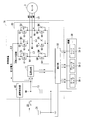
図1に示すように、制御装置1は、電源回路11、蓄電部13及びUVW出力回路20を備える。また、制御装置1は、スイッチ22を介してバッテリ21に接続されている。また、制御装置1は、モータ3及び補機(負荷)30に接続されている。
バッテリ21は、例えば、二次電池であり、モータ3を駆動する駆動電力を電力供給線L1に供給する。また、バッテリ21は、モータ3に回生電力が発生した場合に、電力供給線L1を介して回生電力を充電する。
スイッチ22は、例えば、インジェクションスイッチやバッテリ21内に設けられる遮断スイッチである。本実施形態では、一例として、スイッチ22がバッテリ21内に設けられる遮断スイッチである場合について説明する。
スイッチ22は、バッテリ21が満充電状態になり、モータ3により発生した回生電力を吸収できない場合に、非導通状態(OFF(オフ)状態)されてバッテリ21への回生電力の供給を遮断する。
なお、バッテリ装置2は、不図示のバッテリマネジメントユニット(バッテリ管理部)を備えており、スイッチ22は、当該バッテリマネジメントユニットにより導通状態が制御される。すなわち、バッテリマネジメントユニットは、モータ3に回生電力が発生していない場合、又は、モータ3に回生電力が発生してバッテリ21が満充電状態でない場合に、スイッチ22を導通状態(ON(オン)状態)に制御する。また、バッテリマネジメントユニットは、モータ3に回生電力が発生してバッテリ21が満充電状態である場合に、スイッチ22を非導通状態(OFF状態)にして、バッテリ21への回生電力の供給を遮断させる。
モータ3は、例えば、車両走行用の3相モータである。モータ3は、UVW出力回路20から出力される3相の駆動信号(MU、MV、MW)によって駆動される。また、モータ3は、回転の減速、又は外部からの力による回転により回生電力が発生した場合には、その回生電力を制御装置1に供給する。
UVW出力回路20は、制御装置1内に備えられている制御回路(不図示)から出力される制御信号G1~G6に基づいて、モータ3を駆動する駆動信号(MU、MV、MW)を生成し、その生成した駆動信号(MU、MV、MW)をモータ3に供給する。ここで、駆動信号(MU、MV、MW)は、互いに位相が120度ずれた3相の交流信号である。また、UVW出力回路20は、スイッチ素子Q1~Q6と、寄生ダイオードD1~D6とを備えている。
スイッチ素子Q1~Q6は、例えば、NMOS型電界効果トランジスタ(NMOS型FET)である。ここで、スイッチ素子Q1~Q3は、バッテリ21から駆動電力を駆動信号線L3~L5に供給する第1スイッチ素子である。また、スイッチ素子Q4~Q6は、スイッチ素子Q1~Q6の耐圧以下の基準電位の信号線(例えば、GND信号線L2)と、駆動信号線L3~L5との間に接続される第2スイッチ素子である。
スイッチ素子Q1は、ドレイン端子が電力供給線L1に、ゲート端子が制御信号G1の信号線に、ソース端子がノードN4に、それぞれ接続されている。また、スイッチ素子Q4は、ドレイン端子がノードN4に、ゲート端子が制御信号G4の信号線に、ソース端子がGND信号線L2に、それぞれ接続されている。スイッチ素子Q1及びスイッチ素子Q4は、制御信号G1及び制御信号G4に基づいて導通状態が制御され、ノードN4に駆動信号MUを生成し、駆動信号線L3を介して、駆動信号MUをモータ3に供給する。
スイッチ素子Q2は、ドレイン端子が電力供給線L1に、ゲート端子が制御信号G2の信号線に、ソース端子がノードN5に、それぞれ接続されている。また、スイッチ素子Q5は、ドレイン端子がノードN5に、ゲート端子が制御信号G5の信号線に、ソース端子がGND信号線L2に、それぞれ接続されている。スイッチ素子Q2及びスイッチ素子Q5は、制御信号G2及び制御信号G5に基づいて導通状態が制御され、ノードN5に駆動信号MVを生成し、駆動信号線L5を介して、駆動信号MVをモータ3に供給する。
スイッチ素子Q3は、ドレイン端子が電力供給線L1に、ゲート端子が制御信号G3の信号線に、ソース端子がノードN6に、それぞれ接続されている。また、スイッチ素子Q6は、ドレイン端子がノードN6に、ゲート端子が制御信号G6の信号線に、ソース端子がGND信号線L2に、それぞれ接続されている。スイッチ素子Q3及びスイッチ素子Q6は、制御信号G3及び制御信号G6に基づいて導通状態が制御され、ノードN6に駆動信号MWを生成し、駆動信号線L6を介して、駆動信号MWをモータ3に供給する。
寄生ダイオードD1は、スイッチ素子Q1の寄生ダイオードであり、アノード端子がノードN4に、カソード端子が電力供給線L1に、それぞれ接続されている。寄生ダイオードD1は、モータ3に回生電力が発生した場合に、駆動信号線L3から電力供給線L1に回生電力を供給する。
寄生ダイオードD2は、スイッチ素子Q2の寄生ダイオードであり、アノード端子がノードN5に、カソード端子が電力供給線L1に、それぞれ接続されている。寄生ダイオードD2は、モータ3に回生電力が発生した場合に、駆動信号線L4から電力供給線L1に回生電力を供給する。
寄生ダイオードD2は、スイッチ素子Q2の寄生ダイオードであり、アノード端子がノードN5に、カソード端子が電力供給線L1に、それぞれ接続されている。寄生ダイオードD2は、モータ3に回生電力が発生した場合に、駆動信号線L4から電力供給線L1に回生電力を供給する。
寄生ダイオードD3は、スイッチ素子Q3の寄生ダイオードであり、アノード端子がノードN6に、カソード端子が電力供給線L1に、それぞれ接続されている。寄生ダイオードD3は、モータ3に回生電力が発生した場合に、駆動信号線L5から電力供給線L1に回生電力を供給する。
寄生ダイオードD4は、スイッチ素子Q4の寄生ダイオードであり、アノード端子がGND信号線L2に、カソード端子がノードN4に、それぞれ接続されている。
寄生ダイオードD5は、スイッチ素子Q5の寄生ダイオードであり、アノード端子がGND信号線L2に、カソード端子がノードN5に、それぞれ接続されている。
寄生ダイオードD6は、スイッチ素子Q6の寄生ダイオードであり、アノード端子がGND信号線L2に、カソード端子がノードN6に、それぞれ接続されている。
なお、寄生ダイオードD1~D6は、モータ3に発生した回生電力である交流信号を整流する整流回路として機能する。
寄生ダイオードD5は、スイッチ素子Q5の寄生ダイオードであり、アノード端子がGND信号線L2に、カソード端子がノードN5に、それぞれ接続されている。
寄生ダイオードD6は、スイッチ素子Q6の寄生ダイオードであり、アノード端子がGND信号線L2に、カソード端子がノードN6に、それぞれ接続されている。
なお、寄生ダイオードD1~D6は、モータ3に発生した回生電力である交流信号を整流する整流回路として機能する。
なお、図1において、正電圧(+の電圧)の回生電力が発生した場合の回生電力の流れを一点鎖線の矢印し、バッテリ21からの電力の流れを実線の矢印で示している。ただし、供給された駆動電力によりモータ3から他の信号線及びスイッチ素子Q4~Q6を経由してGND信号線L2に流れる電流、及び、負電圧(-の電圧)の回生電力が発生した場合についての記載を説明上省略している。
また、モータ3に回生電力が発生する場合としては、例えば、車両の走行中にブレーキをかけて制動した場合や、車両が坂道などを走行中に、インジェクションスイッチをOFF状態にして、バッテリ21と制御装置1との電気接続を遮断した場合などが想定される。
電源回路11には、ノードN1を介して、バッテリ21から出力される電力が供給されるとともに、ノードN1に接続された電力供給線L1を介して、モータ3の回生電力が供給される。
電源回路11は、バッテリ21から供給される電力に基づいて、車両に搭載される補機30を駆動させるための負荷用電力を生成する。
また、電源回路11は、バッテリ21からの電力の供給が遮断された場合には、車両の走行用のモータ3で発生した回生電力を用いて負荷用電力を生成する。例えば、電源回路11は、バッテリ21からの電力の供給が遮断された場合には、蓄電部13に蓄えられた回生電力と、モータ3からの回生電力と、の少なくともいずれか一方の電力から負荷用電力を生成する。このモータ3からの回生電力とは、蓄電部13に蓄電された回生電力ではなく、電力供給線Lを介して電源回路11に直接入力した回生電力である。
また、電源回路11は、バッテリ21からの電力の供給が遮断された場合には、車両の走行用のモータ3で発生した回生電力を用いて負荷用電力を生成する。例えば、電源回路11は、バッテリ21からの電力の供給が遮断された場合には、蓄電部13に蓄えられた回生電力と、モータ3からの回生電力と、の少なくともいずれか一方の電力から負荷用電力を生成する。このモータ3からの回生電力とは、蓄電部13に蓄電された回生電力ではなく、電力供給線Lを介して電源回路11に直接入力した回生電力である。
ここで、バッテリ21からの電力の供給が遮断された場合とは、車両が坂道などを走行中に、インジェクションスイッチがOFF状態になった場合や、バッテリ21が満充電状態となりスイッチ22がOFF状態になった場合、又はバッテリ21の接続が外れてしまった場合である。電源回路11は、例えば、DC/DCコンバータである。
また、電源回路11は、バッテリ21からの電力の供給が遮断された場合において、車両の走行が停止した後の所定期間において、蓄電部13に蓄電された回生電力から負荷用電力を生成し、その生成した負荷用電力を補機30に供給する。すなわち、電源回路11は、バッテリ21からの電力の供給が遮断され、車両が停止した場合においても、補機30であるテールランプやブレーキランプに対する電力の供給を所定期間継続する。これにより、制御装置1は、後続車両に対して自車両が停止していること、又は異常が発生していることを十分認識させることが可能となり、高い安全性が確保できる。
蓄電部13は、ノードN1(電力供給線L1)と電源GND線(GND信号線L2)との間に配置される。
蓄電部13は、車両の走行中においてモータ3で発生した回生電力を蓄える。例えば、蓄電部13は、二次電池でもよいし、コンデンサでもよいし、それらの組み合わせであってもよい。また、蓄電部13は、さらに、バッテリ21から電源回路11に供給される電力を平滑する機能を備えてもよい。なお、バッテリ21からの電力の供給が遮断された場合において、車両の走行が停止した後の所定期間において、補機30の駆動を継続させる場合には、この蓄電部13の容量値は、所定期間において、補機30の駆動を継続可能な電力を蓄積可能な容量値に設定されている。補機30は、例えば、車両の灯火類のテールランプやブレーキランプである。
蓄電部13は、車両の走行中においてモータ3で発生した回生電力を蓄える。例えば、蓄電部13は、二次電池でもよいし、コンデンサでもよいし、それらの組み合わせであってもよい。また、蓄電部13は、さらに、バッテリ21から電源回路11に供給される電力を平滑する機能を備えてもよい。なお、バッテリ21からの電力の供給が遮断された場合において、車両の走行が停止した後の所定期間において、補機30の駆動を継続させる場合には、この蓄電部13の容量値は、所定期間において、補機30の駆動を継続可能な電力を蓄積可能な容量値に設定されている。補機30は、例えば、車両の灯火類のテールランプやブレーキランプである。
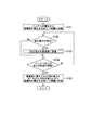
次に、図2を参照して、本実施形態による制御装置1の動作について説明する。
図2に示すように、制御装置1は、バッテリ21の電圧から負荷用電力を生成して、その生成した負荷用電力を補機30に供給する(ステップS101)。これにより、補機30は、制御装置1から供給される負荷用電力に基づいて、駆動可能となる。
図2に示すように、制御装置1は、バッテリ21の電圧から負荷用電力を生成して、その生成した負荷用電力を補機30に供給する(ステップS101)。これにより、補機30は、制御装置1から供給される負荷用電力に基づいて、駆動可能となる。
モータ3に回生電力が発生した場合(ステップS102:YES)に、寄生ダイオードD1~D3を介して、電力供給線L1に、回生電力が供給される(ステップS102、図1の一点鎖線の矢印を参照)。そして、蓄電部13は、電力供給線L1を介して供給された回生電力を蓄電する(ステップS103)。なお、制御装置1は、回生電力が発生していない場合(ステップS101:NO)には、ステップS104の処理に移行する。
次に、制御装置1は、バッテリ21からの電力の供給が遮断されたか否かを判定する(ステップS104)。制御装置1は、バッテリ21からの電力の供給が遮断されていないと判定した場合(ステップS104:NO)に、ステップS102の動作を実行する。また、電源回路11は、バッテリ21からの電力の供給が遮断されていると判定した場合(ステップS104:YES)に、蓄電部13に蓄えられた回生電力とモータ3からの回生電力との少なくともいずれか一方の電力から負荷用電力を生成する。そして、電源回路11は、その生成した負荷用電力を補機30に供給する。これにより、バッテリ21からの電力の供給が遮断された場合でも、回生電力に利用して負荷用電力を生成することができる。
なお、車両が停止すると、回生電力が発生しなくなる。そのため、電源回路11は、モータ3で発生した回生電力から直接的に負荷用電力を生成することができない。この場合において、蓄電部13は、車両の走行時において蓄電していた回生電力を電源回路11に供給する。これにより、電源回路11は、蓄電部13から供給された回生電力に基づいて負荷用電力を生成し、その生成した負荷用電力を補機30に供給する。これにより、バッテリ21からの電力の供給が遮断され、且つ車両が停止した場合でも、所定期間の間、補機の駆動を継続することができる。
次に、図3を参照して、本実施形態による制御装置1の動作の詳細について説明する。
図3において、上から順に、車両の状態、バッテリ21の接続状態、バッテリ21からの電力出力の状態、モータ3からの回生電力の状態、蓄電部13の出力電力(又は出力電圧)の状態及び補機30の電源状態を示している。なお、図3に示すグラフの横軸は、時間を示している。
図3において、上から順に、車両の状態、バッテリ21の接続状態、バッテリ21からの電力出力の状態、モータ3からの回生電力の状態、蓄電部13の出力電力(又は出力電圧)の状態及び補機30の電源状態を示している。なお、図3に示すグラフの横軸は、時間を示している。
また、波形W1は、電力供給線L1の電力波形を示し、波形W2は、蓄電部13に蓄電される電力の波形を示し、波形W3は、補機30に供給される電力の波形を示している。
また、初期状態において、回生電力の状態は、“未発生”であり、バッテリ21の接続状態は、“接続”であるものとする。
まず、時刻T1において、イグニッションスイッチがオンされたとする。この場合には、バッテリ21から蓄電部13を経由して電源回路11に電力が供給される。そのため、電源回路11は、バッテリ21から供給される電力から負荷用電力を生成し、その生成した負荷用電力を補機30に出力する。これにより、補機30の電源状態はオン状態となる。
次に、時刻T2において、車両が走行することで、モータ3に回生電力が発生すると、駆動信号線L3~L5から寄生ダイオードD1~D3を介して、回生電力が電力供給線L1に供給される。なお、バッテリ21の接続状態が“接続”であるため、この回生電力は、バッテリ21の充電に消費されてもよいし、蓄電部13により蓄電されてもよいし、電源回路11による負荷用電力の生成に使用されてもよい。
次に、時刻T3において、バッテリ21からの電力の供給が遮断されたとする。例えば、バッテリ21が満充電状態になり、スイッチ22がOFF状態になることで、バッテリ21の接続状態が“遮断”になったとする。この場合においても、モータ3からの回生電力が電力供給線L1に供給されている。そのため、電源回路11は、回生電力を用いて負荷用電力を生成し、その生成した負荷用電力を補機30に供給する。この場合の負荷用電力は、蓄電部13に蓄えられた回生電力と、電力供給線から直接供給された回生電力と、の少なくともいずれか一方の電力から生成される。
なお、回生電力の発生に伴い、モータ3に制動力が発生するため、車両の速度は低下する。そして、時刻T4において、車両が停止することでバッテリ21における回生電力の発生が停止する。この場合において、蓄電部13は、車両の走行時において蓄電していた回生電力を電源回路11に供給する。そして、電源回路11は、蓄電部13から供給された回生電力に基づいて負荷用電力を生成し、その生成した負荷用電力を補機30に供給する。これにより、電源回路11は、回生電力が発生しなくなった時刻T4から時刻T5までの所定期間の間において、補機30の駆動を継続させることができる。すなわち、制御装置1は、車両が停止した場合でも、所定の期間の間、補機30であるテールランプやブレーキランプを点灯させることができ、後続車両に対する自車の視認性を確保することができる。
上述したように、第1の実施形態における制御装置1は、バッテリ21から供給される電力から、車両に搭載される補機30を駆動させるための負荷用電力を生成し、その生成した負荷用電力を補機30に供給する。そして、制御装置1は、バッテリ21からの電力の供給が遮断された場合には、車両の走行用のモータ3で発生した回生電力を用いて負荷用電力を生成する。これにより、サブバッテリを用いない場合において、車両の走行中にメインバッテリであるバッテリ21からの電力の供給が停止された場合に、その電力供給の停止と同時に、補機30に対する電力の供給が停止されない。したがって、制御装置1は、バッテリ21からの電力の供給が停止された場合に、車両の走行中において補機30であるテールランプやブレーキランプを点灯させることができ、後続車両に対する自車両の視認性の低下を抑制することができる。
また、第1の実施形態における制御装置1は、車両の走行が停止した後の所定期間において、蓄電部13に蓄えられた回生電力から負荷用電力を生成し、その生成した負荷用電力を補機に供給する。これにより、車両の走行が停止した後の所定期間においても、補機30であるテールランプやブレーキランプを点灯させることができ、後続車両に対する自車両の視認性の低下を抑制することができる。
(第2の実施形態)
以下、図4を参照して、第2の実施形態における制御装置1Aについて説明する。第2の実施形態における制御装置1Aは、第1の実施形態と比較して、遮断検出部40及び選択部50を備えた構成である。
以下、図4を参照して、第2の実施形態における制御装置1Aについて説明する。第2の実施形態における制御装置1Aは、第1の実施形態と比較して、遮断検出部40及び選択部50を備えた構成である。
図4に示すように、制御装置1Aは、電源回路11、蓄電部13及びUVW出力回路20、遮断検出部40及び選択部50を備える。
遮断検出部40は、バッテリ21からの電力の供給が遮断されたことを検出する。そして、遮断検出部40は、その検出結果を選択部50に出力する。例えば、遮断検出部40は、スイッチ22がオン状態からオフ状態に移行したことを検出することで、バッテリ21からの電力の供給が遮断されたことを検出する。
遮断検出部40は、バッテリ21からの電力の供給が遮断されたことを検出する。そして、遮断検出部40は、その検出結果を選択部50に出力する。例えば、遮断検出部40は、スイッチ22がオン状態からオフ状態に移行したことを検出することで、バッテリ21からの電力の供給が遮断されたことを検出する。
選択部50は、遮断検出部40によりバッテリ21からの電力の供給が遮断されたことが検出された場合には、複数ある補機30(30-1~30-2)のうち、車両が停止又は停止することを知らせる機能を有する補機30に負荷用電力を供給可能とするように、負荷用電力の供給先を選択する。ここで、車両が停止又は停止することを知らせる機能を有する補機30とは、例えば、テールランプ30-1やブレーキランプ30-2である。換言すれば、制御装置1Aは、車両が停止又は停止することを知らせる機能を有する補機30以外の補機には、負荷用電力を供給しない。例えば、車両の走行中において、バッテリ21に異常が発生しバッテリ21からの電力の供給が停止された場合には、その車両は、走行速度が低下し、その後停止してしまう。したがって、この場合において、まず重要なことは、後続車両に自車両が停止することを知らせることである。そして、回生電力は車両の走行中においてのみ発生する電力である。そのため、優先度の低い補機(自車両が停止することを知らせる機能を有さない補機)、例えばヘッドライト30-3に対しては負荷用電力を供給せずに、優先度の高い補機(自車両が停止することを知らせる機能を有する補機)、例えばテールランプ30-1やブレーキランプ30-2に補機電力を供給する。これにより、制御装置1Aは、バッテリ21からの電力の供給が停止された場合に、車両の走行中や車両の停止後の所定期間において、後続車両に対する自車両の視認性の低下を確実に抑制することができる。
以上、この発明の実施形態について図面を参照して詳述してきたが、具体的な構成はこの実施形態に限られるものではなく、この発明の要旨を逸脱しない範囲の設計等も含まれる。
上記の実施形態において、UVW出力回路20は、ダイオードとして、スイッチ素子Q1~Q6の寄生ダイオードD1~D6を備える例を説明したが、寄生ダイオードD1~D6とは別にダイオード素子を備えるようにしてもよい。
また、上記の実施形態において、スイッチ素子Q1~Q6は、NMOS型電界効果トランジスタ(NMOS型FET)である例を説明したが、例えば、PMOS型電界効果トランジスタ(PMOS型FET)であってもよいし、他のFETや、他のスイッチ素子であってもよい。
また、上記の実施形態において、スイッチ素子Q1~Q6は、NMOS型電界効果トランジスタ(NMOS型FET)である例を説明したが、例えば、PMOS型電界効果トランジスタ(PMOS型FET)であってもよいし、他のFETや、他のスイッチ素子であってもよい。
また、上記の実施形態において、蓄電部13は、車両の走行中において、バッテリ21からの電力の供給が遮断された場合には、モータ3で発生した回生電力を蓄電してもよい。そして、蓄電部13は、上述の所定期間において、電源回路11の入力電圧が所定値以上に保持されるように車両の走行中において蓄電した回生電力を電源回路11に供給する。この所定値とは、電源回路11が補機30の駆動電圧を出力するために必要な電圧である。
上述の実施形態において、制御装置1,1Aは、ハードウエアにより実現されてもよく、ソフトウエアにより実現されてもよく、ハードウエアとソフトウエアとの組み合わせにより実現されてもよい。また、プログラムが実行されることにより、コンピュータが、制御装置1,1Aの一部として機能してもよい。プログラムは、コンピュータ読み取り可能な媒体に記憶されていてもよく、ネットワークに接続された記憶装置に記憶されていてもよい。
1 制御装置
3 モータ
11 電源回路
13 蓄電部
21 バッテリ
22 スイッチ
30 補機(負荷)
40 遮断検出部
50 選択部
3 モータ
11 電源回路
13 蓄電部
21 バッテリ
22 スイッチ
30 補機(負荷)
40 遮断検出部
50 選択部
Claims (10)
- バッテリから供給される電力から、車両に搭載される負荷を駆動させるための負荷用電力を生成し、前記生成した前記負荷用電力を前記負荷に供給する制御装置であって、
前記バッテリからの電力の供給が遮断された場合には、前記車両の走行用のモータで発生した回生電力を用いて前記負荷用電力を生成する電源回路を備える制御装置。 - 前記車両の走行中において前記走行用のモータで発生した回生電力を蓄える蓄電部をさらに備え、
前記電源回路は、前記バッテリからの電力の供給が遮断された場合には、前記蓄電部に蓄えられた回生電力と、前記走行用のモータからの回生電力と、の少なくともいずれか一方の電力から前記負荷用電力を生成する請求項1に記載の制御装置。 - 前記バッテリからの電力の供給が遮断された場合において、
前記電源回路は、前記車両の走行が停止した後の所定期間において、前記蓄電部に蓄えられた回生電力から前記負荷用電力を生成し、前記生成した前記負荷用電力を前記負荷に供給する請求項2に記載の制御装置。 - 前記蓄電部は、さらに、前記バッテリから前記電源回路に供給される電力を平滑する請求項2又は請求項3のいずれか一項に記載の制御装置。
- 前記バッテリからの電力の供給が遮断された場合には、複数ある前記負荷のうち、前記車両が停止又は停止することを知らせる機能を有する負荷に前記負荷用電力を供給可能とするように、前記負荷用電力の供給先を選択する選択部をさらに備える請求項1から請求項4のいずれか一項に記載の制御装置。
- 前記制御装置は、前記バッテリからの電力の供給が遮断されていない場合には、前記走行用のモータで発生した回生電力で前記バッテリを充電する請求項1から請求項5のいずれか一項に記載の制御装置。
- 前記車両は、電動二輪車である請求項1から請求項6のいずれか一項に記載の制御装置。
- 前記蓄電部は、前記車両の走行中において、前記バッテリからの電力の供給が遮断された場合には、前記モータで発生した回生電力を蓄電する請求項2から請求項4のいずれか一項に記載の制御装置。
- 前記蓄電部は、前記車両の走行が停止した後の所定期間において、前記電源回路の入力電圧が所定値以上に保持されるように、前記車両の走行中において蓄電した前記回生電力を前記電源回路に供給する請求項8に記載の制御装置。
- 前記所定値は、前記電源回路が前記負荷の駆動電圧を生成するために必要な電圧に設定される請求項9に記載の制御装置。
Priority Applications (1)
| Application Number | Priority Date | Filing Date | Title |
|---|---|---|---|
| PCT/JP2016/076792 WO2018047333A1 (ja) | 2016-09-12 | 2016-09-12 | 制御装置 |
Applications Claiming Priority (1)
| Application Number | Priority Date | Filing Date | Title |
|---|---|---|---|
| PCT/JP2016/076792 WO2018047333A1 (ja) | 2016-09-12 | 2016-09-12 | 制御装置 |
Publications (1)
| Publication Number | Publication Date |
|---|---|
| WO2018047333A1 true WO2018047333A1 (ja) | 2018-03-15 |
Family
ID=61562678
Family Applications (1)
| Application Number | Title | Priority Date | Filing Date |
|---|---|---|---|
| PCT/JP2016/076792 Ceased WO2018047333A1 (ja) | 2016-09-12 | 2016-09-12 | 制御装置 |
Country Status (1)
| Country | Link |
|---|---|
| WO (1) | WO2018047333A1 (ja) |
Citations (4)
| Publication number | Priority date | Publication date | Assignee | Title |
|---|---|---|---|---|
| JPH03251002A (ja) * | 1990-02-27 | 1991-11-08 | Toyota Motor Corp | 電気自動車のモータ制御装置 |
| JP2001095108A (ja) * | 1999-09-21 | 2001-04-06 | Yamaha Motor Co Ltd | ハイブリッド駆動式移動体の運転方法 |
| JP2004056934A (ja) * | 2002-07-22 | 2004-02-19 | Railway Technical Res Inst | 補助電源装置 |
| JP2009183089A (ja) * | 2008-01-31 | 2009-08-13 | Hitachi Ltd | 蓄電装置の制御装置及びそれを搭載した移動体 |
-
2016
- 2016-09-12 WO PCT/JP2016/076792 patent/WO2018047333A1/ja not_active Ceased
Patent Citations (4)
| Publication number | Priority date | Publication date | Assignee | Title |
|---|---|---|---|---|
| JPH03251002A (ja) * | 1990-02-27 | 1991-11-08 | Toyota Motor Corp | 電気自動車のモータ制御装置 |
| JP2001095108A (ja) * | 1999-09-21 | 2001-04-06 | Yamaha Motor Co Ltd | ハイブリッド駆動式移動体の運転方法 |
| JP2004056934A (ja) * | 2002-07-22 | 2004-02-19 | Railway Technical Res Inst | 補助電源装置 |
| JP2009183089A (ja) * | 2008-01-31 | 2009-08-13 | Hitachi Ltd | 蓄電装置の制御装置及びそれを搭載した移動体 |
Similar Documents
| Publication | Publication Date | Title |
|---|---|---|
| JP6237671B2 (ja) | 電力変換装置 | |
| JP6291899B2 (ja) | 回転電機制御装置 | |
| JP5716715B2 (ja) | 車両用回転電機 | |
| WO2012164680A1 (ja) | 車両および車両の制御方法 | |
| JP6284496B2 (ja) | 電圧変換装置 | |
| WO2018163494A1 (ja) | 車両電源装置 | |
| CN109792222B (zh) | 用于切断机动车的电流激励式同步电机的方法 | |
| JP2014158399A (ja) | 回転電機駆動装置 | |
| JP2017118815A (ja) | インバータ制御回路 | |
| JPWO2017130668A1 (ja) | 電力変換装置 | |
| JP6324575B1 (ja) | 電力変換装置 | |
| JP6829069B2 (ja) | 鉄道車両用回路システム | |
| JPWO2015050068A1 (ja) | 電力変換装置 | |
| JPWO2020008549A1 (ja) | 無停電電源装置 | |
| JP6167989B2 (ja) | 車両用発電機 | |
| US9673692B2 (en) | Application of normally closed power semiconductor devices | |
| JP6671402B2 (ja) | 車両用電源装置 | |
| KR20150093379A (ko) | 하이브리드 차량의 배터리 방전 방지시스템 및 이를 이용한 하이브리드 차량의 배터리 방전 방지방법 | |
| EP3054586A1 (en) | Drive unit and transport machine | |
| WO2018047333A1 (ja) | 制御装置 | |
| JP2019004594A (ja) | 車両の電源装置 | |
| JP5644131B2 (ja) | 電源装置及び電源装置制御方法 | |
| JP2014204627A (ja) | 電力変換装置 | |
| JP6285290B2 (ja) | 電力変換装置 | |
| JP6376026B2 (ja) | 電源制御システム |
Legal Events
| Date | Code | Title | Description |
|---|---|---|---|
| 121 | Ep: the epo has been informed by wipo that ep was designated in this application |
Ref document number: 16915751 Country of ref document: EP Kind code of ref document: A1 |
|
| NENP | Non-entry into the national phase |
Ref country code: DE |
|
| 122 | Ep: pct application non-entry in european phase |
Ref document number: 16915751 Country of ref document: EP Kind code of ref document: A1 |
|
| NENP | Non-entry into the national phase |
Ref country code: JP |