WO2018043293A1 - 電子スコープ及び電子内視鏡システム - Google Patents
電子スコープ及び電子内視鏡システム Download PDFInfo
- Publication number
- WO2018043293A1 WO2018043293A1 PCT/JP2017/030383 JP2017030383W WO2018043293A1 WO 2018043293 A1 WO2018043293 A1 WO 2018043293A1 JP 2017030383 W JP2017030383 W JP 2017030383W WO 2018043293 A1 WO2018043293 A1 WO 2018043293A1
- Authority
- WO
- WIPO (PCT)
- Prior art keywords
- light
- light source
- wavelength
- electronic
- source device
- Prior art date
Links
Images


Classifications
-
- A—HUMAN NECESSITIES
- A61—MEDICAL OR VETERINARY SCIENCE; HYGIENE
- A61B—DIAGNOSIS; SURGERY; IDENTIFICATION
- A61B1/00—Instruments for performing medical examinations of the interior of cavities or tubes of the body by visual or photographical inspection, e.g. endoscopes; Illuminating arrangements therefor
- A61B1/06—Instruments for performing medical examinations of the interior of cavities or tubes of the body by visual or photographical inspection, e.g. endoscopes; Illuminating arrangements therefor with illuminating arrangements
- A61B1/07—Instruments for performing medical examinations of the interior of cavities or tubes of the body by visual or photographical inspection, e.g. endoscopes; Illuminating arrangements therefor with illuminating arrangements using light-conductive means, e.g. optical fibres
-
- A—HUMAN NECESSITIES
- A61—MEDICAL OR VETERINARY SCIENCE; HYGIENE
- A61B—DIAGNOSIS; SURGERY; IDENTIFICATION
- A61B1/00—Instruments for performing medical examinations of the interior of cavities or tubes of the body by visual or photographical inspection, e.g. endoscopes; Illuminating arrangements therefor
- A61B1/00002—Operational features of endoscopes
- A61B1/00004—Operational features of endoscopes characterised by electronic signal processing
- A61B1/00006—Operational features of endoscopes characterised by electronic signal processing of control signals
-
- A—HUMAN NECESSITIES
- A61—MEDICAL OR VETERINARY SCIENCE; HYGIENE
- A61B—DIAGNOSIS; SURGERY; IDENTIFICATION
- A61B1/00—Instruments for performing medical examinations of the interior of cavities or tubes of the body by visual or photographical inspection, e.g. endoscopes; Illuminating arrangements therefor
- A61B1/04—Instruments for performing medical examinations of the interior of cavities or tubes of the body by visual or photographical inspection, e.g. endoscopes; Illuminating arrangements therefor combined with photographic or television appliances
- A61B1/043—Instruments for performing medical examinations of the interior of cavities or tubes of the body by visual or photographical inspection, e.g. endoscopes; Illuminating arrangements therefor combined with photographic or television appliances for fluorescence imaging
-
- A—HUMAN NECESSITIES
- A61—MEDICAL OR VETERINARY SCIENCE; HYGIENE
- A61B—DIAGNOSIS; SURGERY; IDENTIFICATION
- A61B1/00—Instruments for performing medical examinations of the interior of cavities or tubes of the body by visual or photographical inspection, e.g. endoscopes; Illuminating arrangements therefor
- A61B1/06—Instruments for performing medical examinations of the interior of cavities or tubes of the body by visual or photographical inspection, e.g. endoscopes; Illuminating arrangements therefor with illuminating arrangements
- A61B1/0638—Instruments for performing medical examinations of the interior of cavities or tubes of the body by visual or photographical inspection, e.g. endoscopes; Illuminating arrangements therefor with illuminating arrangements providing two or more wavelengths
-
- A—HUMAN NECESSITIES
- A61—MEDICAL OR VETERINARY SCIENCE; HYGIENE
- A61B—DIAGNOSIS; SURGERY; IDENTIFICATION
- A61B1/00—Instruments for performing medical examinations of the interior of cavities or tubes of the body by visual or photographical inspection, e.g. endoscopes; Illuminating arrangements therefor
- A61B1/06—Instruments for performing medical examinations of the interior of cavities or tubes of the body by visual or photographical inspection, e.g. endoscopes; Illuminating arrangements therefor with illuminating arrangements
- A61B1/0646—Instruments for performing medical examinations of the interior of cavities or tubes of the body by visual or photographical inspection, e.g. endoscopes; Illuminating arrangements therefor with illuminating arrangements with illumination filters
-
- A—HUMAN NECESSITIES
- A61—MEDICAL OR VETERINARY SCIENCE; HYGIENE
- A61B—DIAGNOSIS; SURGERY; IDENTIFICATION
- A61B1/00—Instruments for performing medical examinations of the interior of cavities or tubes of the body by visual or photographical inspection, e.g. endoscopes; Illuminating arrangements therefor
- A61B1/06—Instruments for performing medical examinations of the interior of cavities or tubes of the body by visual or photographical inspection, e.g. endoscopes; Illuminating arrangements therefor with illuminating arrangements
- A61B1/0653—Instruments for performing medical examinations of the interior of cavities or tubes of the body by visual or photographical inspection, e.g. endoscopes; Illuminating arrangements therefor with illuminating arrangements with wavelength conversion
-
- A—HUMAN NECESSITIES
- A61—MEDICAL OR VETERINARY SCIENCE; HYGIENE
- A61B—DIAGNOSIS; SURGERY; IDENTIFICATION
- A61B1/00—Instruments for performing medical examinations of the interior of cavities or tubes of the body by visual or photographical inspection, e.g. endoscopes; Illuminating arrangements therefor
- A61B1/06—Instruments for performing medical examinations of the interior of cavities or tubes of the body by visual or photographical inspection, e.g. endoscopes; Illuminating arrangements therefor with illuminating arrangements
- A61B1/0655—Control therefor
-
- A—HUMAN NECESSITIES
- A61—MEDICAL OR VETERINARY SCIENCE; HYGIENE
- A61B—DIAGNOSIS; SURGERY; IDENTIFICATION
- A61B1/00—Instruments for performing medical examinations of the interior of cavities or tubes of the body by visual or photographical inspection, e.g. endoscopes; Illuminating arrangements therefor
- A61B1/06—Instruments for performing medical examinations of the interior of cavities or tubes of the body by visual or photographical inspection, e.g. endoscopes; Illuminating arrangements therefor with illuminating arrangements
- A61B1/0661—Endoscope light sources
- A61B1/0669—Endoscope light sources at proximal end of an endoscope
-
- A—HUMAN NECESSITIES
- A61—MEDICAL OR VETERINARY SCIENCE; HYGIENE
- A61B—DIAGNOSIS; SURGERY; IDENTIFICATION
- A61B1/00—Instruments for performing medical examinations of the interior of cavities or tubes of the body by visual or photographical inspection, e.g. endoscopes; Illuminating arrangements therefor
- A61B1/06—Instruments for performing medical examinations of the interior of cavities or tubes of the body by visual or photographical inspection, e.g. endoscopes; Illuminating arrangements therefor with illuminating arrangements
- A61B1/0661—Endoscope light sources
- A61B1/0684—Endoscope light sources using light emitting diodes [LED]
-
- G—PHYSICS
- G02—OPTICS
- G02B—OPTICAL ELEMENTS, SYSTEMS OR APPARATUS
- G02B23/00—Telescopes, e.g. binoculars; Periscopes; Instruments for viewing the inside of hollow bodies; Viewfinders; Optical aiming or sighting devices
- G02B23/24—Instruments or systems for viewing the inside of hollow bodies, e.g. fibrescopes
- G02B23/2407—Optical details
- G02B23/2461—Illumination
- G02B23/2469—Illumination using optical fibres
-
- G—PHYSICS
- G02—OPTICS
- G02B—OPTICAL ELEMENTS, SYSTEMS OR APPARATUS
- G02B23/00—Telescopes, e.g. binoculars; Periscopes; Instruments for viewing the inside of hollow bodies; Viewfinders; Optical aiming or sighting devices
- G02B23/24—Instruments or systems for viewing the inside of hollow bodies, e.g. fibrescopes
- G02B23/26—Instruments or systems for viewing the inside of hollow bodies, e.g. fibrescopes using light guides
Definitions
- the present invention relates to an electronic scope and an electronic endoscope system.
- Patent Document 1 describes a specific configuration of a light source device used in this type of endoscope system.
- the endoscope system described in Patent Document 1 includes a light source device on which two light emitting diodes (LEDs) are mounted and an optical filter.
- One of the two LEDs is a purple LED that emits light in a purple wavelength band.
- the other LED is a phosphor LED having a blue LED and a yellow phosphor. By mixing blue LED light and yellow fluorescence, pseudo white light is emitted.
- the optical filter is a wavelength selection filter that allows only light in a specific wavelength range to pass through, and is disposed so as to be insertable / removable on the optical path of irradiation light emitted from the phosphor LED.
- the light source device described in Patent Document 1 when the optical filter is extracted from the optical path, the light emitted from the phosphor LED is irradiated to the subject as white light without limiting the wavelength band.
- the optical filter when the optical filter is inserted on the optical path, the subject is irradiated with both the irradiation light emitted from the phosphor LED and the wavelength band limited and the irradiation light emitted from the purple LED.
- the spectral intensity characteristic of the irradiation light and irradiating the subject with only light in a specific wavelength band, it is possible to obtain a captured image in which a specific tissue is emphasized among subjects in the living body.
- the optical fiber has a characteristic of transmitting light in the visible light band.
- the optical fiber has a wavelength dependency of transmittance depending on the material. For example, quartz generally used for optical fibers has a lower transmittance as the wavelength of light becomes shorter. Therefore, when the subject is observed using purple light having a relatively short wavelength, there is a problem that the amount of the purple light is small and the obtained captured image becomes dark. In addition, the optical fiber may be yellowed due to the material used and deterioration with time.
- the present invention provides an electronic scope and an electronic endoscope that can prevent a decrease in the amount of light in a desired wavelength band even if the light transmittance of the optical fiber has different characteristics in the wavelength band. It is to provide a mirror system.
- an electronic scope includes: An insertion tube configured to be inserted into a body cavity and having a light exit at the tip; A light guide configured to guide the first light from the distal end to the distal end of the insertion tube; A light emitting element configured to emit from the tip portion second light in a wavelength band in which the light transmittance in the light guide is equal to or lower than the transmittance in the wavelength band of the first light.
- the optical path length of the second light from the light emitting element to the second light exit provided at the tip is shorter than the optical path length of the first light in the light guide.
- the light emitting element is preferably provided at the tip.
- the second light has a peak wavelength between a wavelength of 405 nm and a wavelength of 425 nm.
- a plurality of solid state light emitting elements are provided at the tip, and the light emitting element is one of the solid state light emitting elements.
- the electronic scope includes a light source device configured to emit the first light to the light guide.
- An electronic endoscope system includes: The electronic scope; An electronic endoscope processor capable of detachably connecting the electronic scope; Is provided.
- the electronic endoscope processor includes: The light source device configured to emit the first light; and A light source driving circuit configured to generate a control signal for controlling light emission of the light emitting element and the light source device; Is provided.
- the electronic endoscope processor has an optical filter that can be inserted into and removed from the optical path of the first light.
- the optical filter has a filter characteristic that transmits only light in a green wavelength band in a visible light band.
- An electronic endoscope system includes: The electronic scope; A light source device configured to emit the first light to the light guide.
- the first light includes light having a longer wavelength than the second light.
- the light source device preferably includes a plurality of light source units configured to emit light having different wavelength bands.
- one of the plurality of light source units is a light source unit configured to emit the second light.
- the electronic endoscope system is configured to generate a control signal for individually controlling light emission of the light emitting element and the light source device according to each of a plurality of modes.
- the light source driving circuit generates at least a first control signal for driving the light source device to emit light in the first mode, and generates a second control signal for driving at least the light emitting element to emit light in the second mode, It is preferable that the light source device and the light emitting element are configured to be controlled.
- the electronic endoscope system includes a light source driving circuit configured to generate a control signal for individually controlling light emission of the solid state light emitting element and the light source device,
- the electronic scope includes an imaging device configured to capture an image of a subject at a predetermined frame period and generate an image signal;
- the light source driving circuit is configured to alternately generate at least a first control signal for driving light emission of the light source device and a second control signal for driving light emission of at least the light emitting element for each frame of the image signal. It is preferable that
- FIG. 1 is a block diagram of an electronic endoscope system according to an embodiment of the present invention. It is a block diagram of the light source device which concerns on the 1st Embodiment of this invention.
- (A), (b) is a figure which shows the spectral intensity distribution of the illumination light based on the 1st Embodiment of this invention. It is a block diagram of the light source device which concerns on the 2nd Embodiment of this invention.
- (A), (b) is a figure which shows the spectral intensity distribution of the illumination light based on the 2nd Embodiment of this invention. It is a block diagram of the light source device which concerns on the 3rd Embodiment of this invention.
- (A), (b) is a figure which shows the spectral intensity distribution of the illumination light based on the 3rd Embodiment of this invention.
- An electronic scope includes: An insertion tube configured to be inserted into a body cavity and having a light exit at the tip; A light guide configured to guide the first light from the distal end to the distal end of the insertion tube; A light emitting device configured to emit from the tip portion second light in a wavelength band in which the light transmittance in the light guide is equal to or lower than the transmittance in the wavelength band of the first light; Is provided.
- the optical path length of the second light from the light emitting element to the second light exit port provided at the tip is shorter than the optical path length of the first light in the light guide that guides the first light.
- the light path length of the second light whose light transmittance in the light guide is equal to or less than the transmittance of the wavelength band of the first light is shorter than the light path length of the ride guide that guides the first light.
- the light emitting element is preferably provided at the tip of the electronic scope. This eliminates the need to guide the second light by the light guide, so that there is no light loss of the second light by the light guide.
- the second light may be emitted from the outlet of the distal end portion using light guide by a ride guide cable. Even in this case, since the length of the light guide cable that guides the second light is short, the light loss due to the light guide of the second light is smaller than when the light guide cable is guided by the same light guide cable as the first light. It is suppressed.
- the light emitting element is preferably configured to emit second light whose light transmittance in the light guide is lower than the transmittance in the wavelength band of the first light.
- FIG. 1 is a block diagram showing a configuration of an electronic endoscope system 1 including an endoscope light source device 201 according to the first embodiment of the present invention.
- the electronic endoscope system 1 is a system specialized for medical use, and includes an electronic scope 100, a processor 200, and a monitor 300.
- the electronic scope 100 includes an insertion tube 101 to be inserted into a human body cavity and a connection portion 102.
- the electronic scope 100 is detachably connected to the processor 200 via the connection unit 102.
- the processor 200 includes a system controller 21 and a timing controller 22.
- the system controller 21 executes various programs stored in the memory 23 and controls the entire electronic endoscope system 1 in an integrated manner.
- the system controller 21 is connected to the operation panel 24.
- the system controller 21 changes each operation of the electronic endoscope system 1 and parameters for each operation in accordance with an instruction from the operator input to the operation panel 24.
- the timing controller 22 outputs a clock pulse for adjusting the operation timing of each unit to each circuit in the electronic endoscope system 1.
- the processor 200 includes a light source device 201.
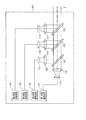
- FIG. 2 shows a block diagram of the light source device 201.
- the light source device 201 includes first to fourth light source units 111 to 114.
- the first to fourth light source units 111 to 114 are individually controlled to emit light by control signals generated by the first to fourth light source drive circuits 141 to 144, respectively.
- the first light source unit 111 is a red LED (Light Emitting Diode) that emits light in a red wavelength band (for example, a wavelength of 620 to 680 nm).
- the second light source unit 112 includes a blue LED that emits light in a blue wavelength band (for example, a wavelength of 430 to 470 nm) and a phosphor. The phosphor is excited by blue LED light emitted from the blue LED, and emits fluorescence in a green wavelength band (for example, a wavelength of 460 to 600 nm).
- the third light source unit 113 is a blue LED that emits light in a blue wavelength band (for example, a wavelength of 430 to 470 nm).
- the fourth light source unit 114 is a purple LED that emits light in a purple wavelength band (for example, a wavelength of 395 to 435 nm).
- Collimating lenses 121 to 124 are arranged in front of the light source units 111 to 114 in the light emission direction, respectively.
- the red LED light emitted from the first light source unit 111 is converted into parallel light by the collimator lens 121 and is incident on the dichroic mirror 131.
- the light emitted from the second light source unit 112, that is, the blue LED light and the green fluorescence is converted into parallel light by the collimator lens 122 and is incident on the dichroic mirror 131.
- the dichroic mirror 131 combines the optical path of the light emitted from the first light source unit 111 and the optical path of the light emitted from the second light source unit 112.
- the dichroic mirror 131 has a cutoff wavelength in the vicinity of a wavelength of 600 nm, has a characteristic of transmitting light having a wavelength longer than the cutoff wavelength, and reflecting light having a wavelength shorter than the cutoff wavelength. Yes. Therefore, the red LED light emitted from the first light source unit 111 passes through the dichroic mirror 131, and the light emitted from the second light source unit 112 is reflected by the dichroic mirror 131. Thereby, the optical path of red LED light, the optical path of blue LED light, and green fluorescence are combined. The light whose optical path is synthesized by the dichroic mirror 131 is incident on the dichroic mirror 132.
- the blue LED light emitted from the third light source unit 113 is converted into parallel light by the collimator lens 123 and is incident on the dichroic mirror 132.
- the dichroic mirror 132 combines the optical path of the light incident from the dichroic mirror 131 and the optical path of the blue LED light emitted from the third light source unit 113.
- the dichroic mirror 132 has a cutoff wavelength in the vicinity of a wavelength of 500 nm, transmits light having a wavelength longer than the cutoff wavelength, and reflects light having a wavelength shorter than the cutoff wavelength. Yes.
- red LED light and green fluorescence pass through the dichroic mirror 132, and blue LED light is reflected by the dichroic mirror 132.
- the blue LED emitted from the third light source unit 113 is reflected by the dichroic mirror 132.
- the optical path of the red LED light and the green fluorescence and the optical path of the blue LED emitted from the third light source unit 113 are combined.
- the light whose optical path is synthesized by the dichroic mirror 132 is incident on the dichroic mirror 133.
- the purple LED light emitted from the fourth light source unit 114 is converted into parallel light by the collimator lens 124 and is incident on the dichroic mirror 133.
- the dichroic mirror 133 combines the optical path of the light incident from the dichroic mirror 132 and the optical path of the purple LED light emitted from the fourth light source unit 114.
- the dichroic mirror 133 has a cutoff wavelength near a wavelength of 430 nm, has a characteristic of transmitting light having a wavelength longer than the cutoff wavelength, and reflecting light having a wavelength shorter than the cutoff wavelength. Yes. Therefore, the light incident from the dichroic mirror 132 and the purple LED light emitted from the fourth light source unit 114 are combined by the dichroic mirror 133 and emitted from the light source device 201 as illumination light L.
- the illumination light L emitted from the light source device 201 is condensed on the incident end face of the LCB (Light Carrying Bundle) 11 by the condenser lens 25 and is incident on the LCB 11.
- LCB Light Carrying Bundle
- the illumination light L incident on the LCB 11 propagates in the LCB 11.
- the illumination light L propagating through the LCB 11 is emitted from the exit end face of the LCB 11 disposed at the distal end portion 101A of the electronic scope 100, and is irradiated onto the subject via the light distribution lens 12 provided at the exit port 101B.
- the return light from the subject illuminated by the illumination light L from the light distribution lens 12 forms an optical image on the light receiving surface of the solid-state imaging device 14 via the objective lens 13.
- the solid-state imaging device 14 is a single-plate color CCD (Charge Coupled Device) image sensor having a Bayer pixel arrangement.
- the solid-state imaging device 14 accumulates an optical image formed by each pixel on the light receiving surface as a charge corresponding to the amount of light, and generates R (Red), G (Green), and B (Blue) image signals. Output.
- the solid-state imaging device 14 is not limited to a CCD image sensor, and may be replaced with a CMOS (Complementary Metal Oxide Semiconductor) image sensor or other types of imaging devices.
- the solid-state image sensor 14 may also be one having a complementary color filter mounted thereon.
- a driver signal processing circuit 15 is provided in the connection part 102 of the electronic scope 100.
- the driver signal processing circuit 15 receives an image signal of a subject from the solid-state imaging device 14 at a predetermined frame period.
- the frame period is, for example, 1/30 seconds.
- the driver signal processing circuit 15 performs a predetermined process on the image signal input from the solid-state imaging device 14 and outputs the processed image signal to the upstream signal processing circuit 26 of the processor 200.
- the driver signal processing circuit 15 also accesses the memory 16 and reads the unique information of the electronic scope 100.
- the unique information of the electronic scope 100 recorded in the memory 16 includes, for example, the number of pixels and sensitivity of the solid-state imaging device 14, an operable frame period, a model number, and the like.
- the driver signal processing circuit 15 outputs the unique information read from the memory 16 to the system controller 21.
- the system controller 21 performs various calculations based on the unique information of the electronic scope 100 and generates a control signal.
- the system controller 21 uses the generated control signal to control the operation and timing of various circuits in the processor 200 so that processing suitable for the electronic scope 100 connected to the processor 200 is performed.
- the timing controller 22 supplies clock pulses to the driver signal processing circuit 15 according to the timing control by the system controller 21.
- the driver signal processing circuit 15 drives and controls the solid-state imaging device 14 at a timing synchronized with the frame period of the video processed on the processor 200 side, according to the clock pulse supplied from the timing controller 22.
- the pre-stage signal processing circuit 26 performs predetermined signal processing such as demosaic processing, matrix calculation, and Y / C separation on the image signal input from the driver signal processing circuit 15 in one frame period, and outputs it to the image memory 27. To do.
- the image memory 27 buffers the image signal input from the upstream signal processing circuit 26 and outputs it to the downstream signal processing circuit 28 according to the timing control by the timing controller 22.
- the post-stage signal processing circuit 28 processes the image signal input from the image memory 27 to generate screen data for monitor display, and converts the generated screen data for monitor display into a predetermined video format signal.
- the converted video format signal is output to the monitor 300. Thereby, the image of the subject is displayed on the display screen of the monitor 300.
- an LED 18 (light emitting element or solid light emitting element) is disposed at the distal end 101A of the insertion tube 101 of the electronic scope 100.
- the light emission of the LED 18 is controlled by a control signal generated by the light source driving circuit 17 provided in the connection unit 102.
- the LED 18 is a purple LED that emits light in a purple wavelength band (for example, a wavelength of 395 to 435 nm).
- the purple LED light emitted from the LED 18 is irradiated to the subject via the light distribution lens 19 provided at the exit port 101C.
- the reason why the LED 18 is provided at the distal end portion 101A is that the light emitted from the LED 108 (second light) is not guided by the LCB 11 that absorbs part of the light.
- the LCB 11 has transmission characteristics with different transmittances depending on the wavelength band of light. For this reason, LED18 inject
- the light emitted from the LED 18 is light in a purple wavelength band.
- the electronic endoscope system 1 has a plurality of observation modes including a normal observation mode and a special observation mode.
- Each observation mode is switched manually or automatically depending on the subject to be observed. For example, when it is desired to observe the subject illuminated with normal light, the observation mode is switched to the normal observation mode.
- the normal light is, for example, white light or pseudo white light.
- White light has a flat spectral intensity distribution in the visible light band.
- the pseudo-white light has a spectral intensity distribution that is not flat, and light in a plurality of wavelength bands is mixed.
- the observation mode is switched to the special observation mode.
- the special light is, for example, light having a high absorbance with respect to a specific living tissue.
- the biological tissue emphasized in the special observation mode is a surface blood vessel will be described.
- the superficial blood vessel contains blood having hemoglobin therein. It is known that hemoglobin has absorbance peaks near wavelengths of 415 nm and 550 nm. Therefore, the superficial blood vessels are emphasized by irradiating the subject with special light suitable for emphasizing the superficial blood vessels (specifically, light having a high intensity near the wavelength of 415 nm, which is the absorbance peak of hemoglobin). Captured images can be obtained. In addition, by irradiating light with a wavelength near 415 nm and special light having a high intensity near the wavelength of 550 nm, which is another peak of the absorbance of hemoglobin, a bright photographed image is maintained while maintaining a state where the surface blood vessels are emphasized. Obtainable.
- the peak of the spectral intensity of the special light does not need to completely match 415 nm.
- the special light only needs to include light having a wavelength of 415 nm.
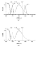
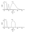
- 3A and 3B show the spectral intensity distribution of the irradiation light L emitted from the electronic scope 100 in each observation mode.
- 3A shows the spectral intensity distribution of the irradiation light L (normal light) in the normal observation mode
- FIG. 3B shows the spectral intensity distribution of the irradiation light L (special light) in the special observation mode.
- the horizontal axis of the spectral intensity distribution shown in FIG. 3 indicates the wavelength (nm), and the vertical axis indicates the intensity of the irradiation light L. Note that the vertical axis is standardized so that the maximum intensity value is 1.
- FIG. 3A shows intensity distributions D111 to D113 and D18 of light emitted from the first to third light source units 111 to 113 and the LED 18.
- the cutoff wavelengths ⁇ 131 to ⁇ 133 of the dichroic mirrors 131 to 133 are indicated by dotted lines.
- a region indicated by a solid line is a region that is emitted from the electronic scope 100 and used as the illumination light L.
- a region indicated by a broken line is a region that is not emitted from the light source device 201 and is not used as the illumination light L.
- the spectral intensity distribution D111 of light emitted from the first light source unit 111 has a steep intensity distribution having a peak at a wavelength of about 650 nm.
- the spectral intensity distribution D112 of light emitted from the second light source unit 112 has peaks at a wavelength of about 450 nm and a wavelength of about 550 nm. These two peaks are the peak of the intensity distribution of the light emitted from the blue LED 112 and the peak of the spectral intensity distribution of the fluorescence emitted from the green phosphor.
- the spectral intensity distribution D113 of light emitted from the third light source unit 113 has a steep intensity distribution having a peak at a wavelength of about 450 nm.
- the spectral intensity distribution D18 of the light emitted from the LED 18 has a steep intensity distribution having a peak at a wavelength of about 415 nm.
- the electronic scope 100 emits illumination light L having a wide wavelength band from the ultraviolet region (part of near ultraviolet) to the red region.
- the spectral intensity distribution of the illumination light L is the sum of the areas indicated by the solid lines in the spectral intensity distributions D111 to D113 and D18 shown in FIG.
- the LED 18 may not be driven to emit light. Even when the LED 18 is not driven to emit light, the illumination light L is emitted with a wide wavelength band from blue to red. By photographing the subject using the illumination light L, a normal color photographed image can be obtained.
- the second light source unit 112 and the LED 18 are driven to emit light, and the first, third, and fourth light source units 111, 113, and 114 are not driven to emit light.
- the intensity around the wavelength of 415 nm, which is the absorbance peak of hemoglobin is relatively higher than the intensity of other wavelength bands, and a captured image in which the surface blood vessels are emphasized can be obtained.
- the light emitted from the second light source unit 112 includes light having a wavelength near 550 nm, which is another peak of the absorbance of hemoglobin. Therefore, by driving the second light source unit 112 to emit light together with the LED 18, the brightness of the captured image can be increased while maintaining the state where the surface blood vessels are emphasized.
- the electronic endoscope system 1 includes the plurality of light source units 111 to 114 and the LEDs 18.
- the light sources 111 to 114 and the LED 18 are individually controlled to emit light according to the observation mode. Therefore, by selecting which one of the light source units 111 to 114 and the LED 18 is driven to emit light, and changing the drive current, the spectral intensity characteristic of the irradiation light L can be switched to one corresponding to the observation mode. it can.
- the electronic endoscope system 1 of the present embodiment has a twin mode in which shooting is performed while the normal observation mode and the special observation mode can be alternately switched as the observation mode.
- the twin mode the observation mode is alternately switched between the normal observation mode and the special observation mode for each frame of the captured image. Therefore, the light emission control of the light source units 111 to 114 and the LED 18 is also switched for each frame of the photographing apparatus. Specifically, when the observation mode is the normal observation mode, the first to third light source units 111 to 113 and the LED 18 are driven to emit light, and the fourth light source unit 114 is not driven to emit light. Further, according to one embodiment, the LED 18 is not driven to emit light.
- the second light source unit 112 and the LED 18 are driven to emit light, and the first, third, and fourth light source units 111, 113, and 114 are not driven to emit light.
- the captured image (normally captured image) captured in the normal observation mode and the captured image (special captured image) captured in the special observation mode are combined by the subsequent signal processing circuit 28. Thereby, the normal captured image and the special captured image are displayed side by side on the monitor 300. Therefore, according to one embodiment, the light source driving circuits 17 and 141 to 144 are configured to generate control signals for individually controlling the light emission of the LED 18 and the light source device 201.
- the electronic scope 100 includes a solid-state imaging device 14 configured to capture an image of a subject at a predetermined frame period and generate an image signal.
- the light source driving circuits 17 and 141 to 144 include one frame of the image signal.
- it is preferable that at least a first control signal for driving the light source device 201 to emit light and a second control signal for driving at least the LED 18 to be switched alternately are generated.
- both the light emitted from the LED 18 and the light emitted from the fourth light source unit 114 are light in a purple wavelength band. Therefore, when the subject is illuminated with light in the purple wavelength band, only one of the LED 18 and the fourth light source unit 114 needs to emit light.
- the purple LED light emitted from the fourth light source unit 114 is irradiated to the subject through the LCB 11.
- the LCB 11 has a characteristic of transmitting visible light, but this transmittance varies depending on the wavelength band, and becomes smaller as the wavelength of light becomes shorter, for example.
- the LCB 11 has a long shape of 1 meter or more from the connection portion 102 of the electronic scope 100 to the distal end portion of the insertion tube 101. Therefore, when the light quantity of the purple LED light incident on the LCB 11 is 100%, the light quantity of the purple LED light emitted from the distal end portion of the insertion tube 101 through the LCB 11 is reduced to about 40%, for example. As a result, the amount of purple LED light applied to the subject decreases, and the captured image may become dark. On the other hand, when the LED 18 disposed at the distal end portion of the insertion tube 101 is caused to emit light instead of the fourth light source unit 114, the purple LED light emitted from the LED 18 loses light amount due to transmission through the LCB 11.
- the light source driving devices 17 and 141 to 144 generate control signals for individually controlling the light emission of the LED 18 (light emitting element) and the light source device 201 according to each of a plurality of modes.
- the light source drive circuits 17, 141 to 144 generate a first control signal for driving to emit at least the light source device 201 in the first mode, and a second control signal for driving to emit at least the LED 18 in the second mode.
- LED18 which inject
- the light source units 111 to 113 are arranged in the light source device 201 of the processor 200.
- the LCB 11 has a relatively high transmittance with respect to blue, green, and red light having wavelengths longer than violet among visible light. Therefore, even if the light source units 111 to 113 are arranged in the light source device 201, the light quantity loss of the light emitted from these light source units 111 to 113 hardly occurs in the LCB 11.
- the light source device 201 shown in FIG. 2 has the 4th light source unit 114 which has purple LED
- embodiment of this invention is not limited to this structure.
- the light source device 201 may not include the light source unit 114.
- various types of electronic scopes 100 are detachably connected to the processor 200. Therefore, it is desirable that the light source device 201 of the processor 200 has the fourth light source unit 114 in preparation for the case where the electronic scope 100 that does not have the LED 18 is connected to the processor 200 for use.
- the electronic endoscope system 1 according to the second embodiment is the same as the electronic endoscope system 1 according to the first embodiment except that the configuration of the light source device 201 of the processor 200 is different.
- FIG. 4 is a block diagram of the light source device 201 included in the processor 200 in the electronic endoscope system 1 according to the second embodiment.
- the light source device 201 includes first and second light source units 211 and 212.
- the first and second light source units 211 and 212 are individually controlled to emit light by control signals generated by the first and second light source drive circuits 241 and 242, respectively.
- the first light source unit 211 is a red LED (Light Emitting Diode) that emits light in a red wavelength band (for example, a wavelength of 620 to 680 nm).
- the second light source unit 212 includes a blue LED that emits light in a blue wavelength band (for example, a wavelength of 430 to 470 nm) and a phosphor. The phosphor is excited by blue LED light emitted from the blue LED, and emits fluorescence in a green wavelength band (for example, a wavelength of 460 to 600 nm).
- Collimating lenses 221 and 222 are arranged in front of the light emission directions of the light source units 211 and 212, respectively.
- the red LED light emitted from the first light source unit 211 is converted into parallel light by the collimator lens 221 and is incident on the dichroic mirror 231.
- the light emitted from the second light source unit 212 that is, the blue LED light and the green fluorescence is converted into parallel light by the collimator lens 222 and is incident on the dichroic mirror 231.
- the dichroic mirror 231 combines the optical path of the light emitted from the first light source unit 211 and the optical path of the light emitted from the second light source unit 212.
- the dichroic mirror 231 has a cutoff wavelength in the vicinity of a wavelength of 600 nm, transmits light having a wavelength longer than the cutoff wavelength, and reflects light having a wavelength shorter than the cutoff wavelength. Yes. Therefore, the red LED light emitted from the first light source unit 211 passes through the dichroic mirror 231, and the light emitted from the second light source unit 212 is reflected by the dichroic mirror 231. Thereby, the optical path of red LED light, the optical path of blue LED light, and green fluorescence are combined. The light whose optical path is synthesized by the dichroic mirror 231 is emitted as illumination light L from the light source device 201.
- FIG. 5 shows the spectral intensity distribution of the irradiation light L emitted from the electronic scope 100 in each observation mode.
- 5A shows a spectral intensity distribution of the irradiation light L (normal light) in the normal observation mode
- FIG. 5B shows a spectral intensity distribution of the irradiation light L (special light) in the special observation mode.
- the horizontal axis of the spectral intensity distribution shown in FIG. 5 indicates the wavelength (nm), and the vertical axis indicates the intensity of the irradiation light L. Note that the vertical axis is standardized so that the maximum intensity value is 1.
- FIG. 5A shows spectral intensity distributions D211, D212, and D18 of light emitted from the first and second light source units 211 and 212 and the LED 18.
- the cutoff wavelength ⁇ 231 of the dichroic mirror 231 is indicated by a dotted line.
- a region indicated by a solid line is a region that is emitted from the electronic scope 100 and used as the illumination light L.
- the optical path of the light emitted from the light source units 211 and 212 is synthesized by the dichroic mirror 231, and the LED 18 is driven to emit light, so that the electronic scope 100 starts from the ultraviolet region (part of near ultraviolet) to red.
- Irradiation light L (normal light) having a wide wavelength band over the region is emitted.
- the spectral intensity distribution of the irradiation light L (normal light) is the sum of the areas indicated by the solid lines in the spectral intensity distributions D211, D212, and D18 shown in FIG.
- the second light source unit 212 and the LED 18 are driven to emit light, and the first light source unit 211 is not driven to emit light.
- the driving current of the second light source unit 212 is set smaller than the driving current in the normal observation mode.
- the intensity around the wavelength of 415 nm, which is the absorbance peak of hemoglobin is relatively higher than the intensity in other wavelength bands, and the captured image in which the surface blood vessels are emphasized is obtained.
- the light emitted from the light source unit 212 includes light having a wavelength near 550 nm, which is another peak of the absorbance of hemoglobin. Therefore, by driving the light source unit 212 to emit light together with the light source unit 211, the brightness of the photographed image can be increased while maintaining the state where the surface blood vessels are emphasized.
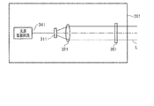
- the electronic endoscope system 1 according to the third embodiment differs from the first and second embodiments in that the light source device 201 includes an optical filter 351 that transmits only light in a specific wavelength band. Is different.
- FIG. 6 is a block diagram of the light source device 201 included in the processor 200 in the electronic endoscope system 1 according to the third embodiment.
- the light source device 201 includes a light source unit 311.
- the light source unit 311 is controlled to emit light by a control signal generated by the light source driving circuit 341.
- the light source unit 311 includes a blue LED that emits light in a blue wavelength band (for example, a wavelength of 430 to 470 nm) and a phosphor.
- the phosphor is excited by blue LED light emitted from the blue LED, and emits fluorescence in a green wavelength band (for example, a wavelength of 460 to 600 nm).
- pseudo white light is emitted from the light source unit 311.
- Light emitted from the light source unit 311 is converted into parallel light by the collimator lens 321.
- the light source device 201 includes an optical filter 351 that can be inserted into and removed from the optical path of light emitted from the light source unit 311.
- the optical filter 351 has a filter characteristic that transmits only light in a wavelength band near a wavelength of 550 nm.
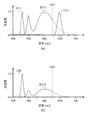
- FIG. 7 shows the spectral intensity distribution of the irradiation light L emitted from the electronic scope 100 in each observation mode.
- FIG. 7A shows the spectral intensity distribution of the irradiation light L (normal light) in the normal observation mode
- FIG. 7B shows the spectral intensity distribution of the irradiation light L (special light) in the special observation mode.
- the horizontal axis of the spectral intensity distribution shown in FIG. 7 indicates the wavelength (nm), and the vertical axis indicates the intensity of the irradiation light L. Note that the vertical axis is standardized so that the maximum intensity value is 1.
- the spectral intensity distribution D311 of light emitted from the light source unit 311 has peaks at wavelengths of about 450 nm and about 550 nm. These two peaks are the peaks of the spectral intensity distribution of blue LED light and green fluorescence, respectively.
- the spectral intensity distribution D18 of light emitted from the LED 18 has a peak at a wavelength of 415 nm.
- the light source unit 311 and the LED 18 are driven to emit light.
- the optical filter 351 is inserted on the optical path. Therefore, the light emitted from the light source unit 311 is limited to light having intensity only in the wavelength band near the wavelength of 550 nm by the optical filter 351.
- the intensities in the vicinity of wavelengths 415 nm and 550 nm, which are the absorption peaks of hemoglobin, are relatively higher than the intensities in other wavelength bands, and the surface blood vessels are emphasized. A photographed image can be obtained.
- the light source device 201 is mounted on the processor 200.
- the light source device 201 is preferably mounted on the electronic scope 100.
- the light source device 201 may be provided in the connection unit 102 or an operation unit that is provided between the connection unit 102 and the distal end portion 101A and operates the electronic scope 100 by the surgeon.
- the light (first light) emitted from the light source device 201 is emitted to the LCB 11 and guided to the tip portion 101A via the LCB 11.
- the light source device 201 is preferably a component device of the electronic endoscope system 1 as a separate device from the processor 200.
- the light source unit 311 is not limited to an LED having a phosphor.
- the light source unit 311 may be a lamp that emits white light, such as a xenon lamp.
- Embodiments of the present invention are not limited to those described above, and various modifications are possible within the scope of the technical idea of the present invention.
- the embodiment of the present invention also includes contents appropriately combined with embodiments or the like clearly shown in the specification or obvious embodiments.
- each light source unit has an LED.
- the present invention is not limited to this, and an LD (Laser ⁇ Diode) can be adopted for each light source unit.
- the LED 18 disposed at the distal end portion of the insertion tube 101 may employ an LD instead of the LED.
- the tip of the insertion tube 101 has one LED 18, but the present invention is not limited to this.
- a plurality of LEDs 18 may be disposed at the distal end portion 101 ⁇ / b> A of the insertion tube 101.
- each light emitted from the LED 18 provided at the tip 101A has a wavelength band in which the light transmittance in the LCB 11 is equal to or lower than that emitted from the light source device 201. It is preferable from the point that the fall of light quantity can be suppressed efficiently.
Abstract
所望の波長帯域の光の光量低下を防止できる電子スコープは、体腔内に挿入されるように構成され、先端部に光の射出口を備える挿入管と、第1光を前記先端部から射出するために、前記挿入管の前記先端部まで導光するように構成されたライトガイドと、前記ライトガイドにおける光透過率が前記第1光の波長帯域の透過率以下である波長帯域の第2光を前記先端部から射出するように構成された発光素子と、を備える。前記発光素子から前記先端部に設けられた前記第2光の射出口までの前記第2光の光路長は、前記ライトガイドにおける前記第1光の光路長に比べて短い。
Description
本発明は、電子スコープ及び電子内視鏡システムに関する。
照射光の分光強度特性を変化させ、特殊な画像を撮影することが可能な内視鏡システムが知られている。例えば特許文献1に、この種の内視鏡システムに使用される光源装置の具体的構成が記載されている。
特許文献1に記載の内視鏡システムは、2つの発光ダイオード(LED:Light Emitting Diode)と光学フィルタが搭載された光源装置を備えている。2つのLEDの内、一方は紫色の波長帯域の光を射出する紫色LEDである。また、他方のLEDは、青色LEDと黄色の蛍光体を有する蛍光体LEDである。青色のLED光と黄色の蛍光を混色することにより、擬似的な白色光を射出する。光学フィルタは、特定の波長域の光のみを通過させる波長選択フィルタであり、蛍光体LEDから射出される照射光の光路上に挿抜可能に配置される。
特許文献1に記載の光源装置では、光学フィルタが光路上から抜出されているときは、蛍光体LEDから射出された光が、波長帯域が制限されることなく、白色光として被写体に照射される。一方、光学フィルタが光路上に挿入されているときは、蛍光体LEDから射出され波長帯域が制限された照射光と、紫色LEDから射出された照射光の両方が被写体に照射される。このように、照射光の分光強度特性を変化させ、特定の波長帯域の光のみを被写体に照射することにより、生体内の被写体のうち、特定の組織を強調した撮影画像を得ることができる。
特許文献1に記載の内視鏡システムでは、光源装置から射出された光は、電子スコープ内の光ファイバ内に入射される。そして、光ファイバ内を導光した光は、電子スコープの先端部から射出される。光ファイバは、可視光帯域の光を透過させる特性を有している。しかし、光ファイバは、その材質に応じて、透過率の波長依存性を有している。例えば、光ファイバに一般的に使用される石英は、光の波長が短くなるほど透過率が低くなる。そのため、波長の比較的短い紫色の光を用いて被写体を観察する場合、紫色の光の光量が少なく、得られる撮影画像が暗くなるという問題があった。また、光ファイバには、使用する材質や経時劣化により黄変が生じる場合がある。この黄変により、光ファイバの紫色の波長帯域の光に対する透過率が低下し、撮影画像が更に暗くなるという問題があった。
このような問題は、光ファイバの光の透過率が波長帯域で異なっていることに起因する。
このような問題は、光ファイバの光の透過率が波長帯域で異なっていることに起因する。
本発明は上記の事情に鑑み、光ファイバの光の透過率が波長帯域で異なる特性を有していても、所望の波長帯域の光の光量低下を防止することができる電子スコープ及び電子内視鏡システムを提供することである。
上記課題を解決するために、本発明の一実施形態に係る電子スコープは、
体腔内に挿入されるように構成され、先端部に光の射出口を備える挿入管と、
第1光を前記先端部から射出するために、前記挿入管の前記先端部まで導光するように構成されたライトガイドと、
前記ライトガイドにおける光透過率が前記第1光の波長帯域の透過率以下である波長帯域の第2光を前記先端部から射出するように構成された発光素子と、を備える。
前記発光素子から前記先端部に設けられた前記第2光の射出口までの前記第2光の光路長は、前記ライトガイドにおける前記第1光の光路長に比べて短い。
体腔内に挿入されるように構成され、先端部に光の射出口を備える挿入管と、
第1光を前記先端部から射出するために、前記挿入管の前記先端部まで導光するように構成されたライトガイドと、
前記ライトガイドにおける光透過率が前記第1光の波長帯域の透過率以下である波長帯域の第2光を前記先端部から射出するように構成された発光素子と、を備える。
前記発光素子から前記先端部に設けられた前記第2光の射出口までの前記第2光の光路長は、前記ライトガイドにおける前記第1光の光路長に比べて短い。
一実施形態によれば、前記発光素子は、前記先端部に設けられている、ことが好ましい。
一実施形態によれば、前記第2光は、波長405nmから波長425nmの間にピーク波長を有する、ことが好ましい。
一実施形態によれば、前記先端部には、複数の固体発光素子が設けられ、前記発光素子は前記固体発光素子の1つである、ことが好ましい。
一実施形態によれば、前記電子スコープは、前記第1光を前記ライトガイドに射出するように構成された光源装置を備える、ことが好ましい。
本発明の他の一実施形態に係る電子内視鏡システムは、
前記電子スコープと、
前記電子スコープを着脱可能に接続可能な電子内視鏡プロセッサと、
を備える。
前記電子内視鏡プロセッサは、
前記第1光を射出するように構成された前記光源装置と、
前記発光素子及び前記光源装置の発光を制御する制御信号を生成するように構成された光源駆動回路と、
を備える。
前記電子スコープと、
前記電子スコープを着脱可能に接続可能な電子内視鏡プロセッサと、
を備える。
前記電子内視鏡プロセッサは、
前記第1光を射出するように構成された前記光源装置と、
前記発光素子及び前記光源装置の発光を制御する制御信号を生成するように構成された光源駆動回路と、
を備える。
一実施形態によれば、前記電子内視鏡プロセッサは、前記第1光の光路に挿抜可能な光学フィルタを有する、ことが好ましい。
一実施形態によれば、前記光学フィルタは、可視光帯域のうち、緑色の波長帯域の光のみを透過させるフィルタ特性を有する、ことが好ましい。
本発明の他の一実施形態に係る電子内視鏡システムは、
前記電子スコープと、
前記第1光を前記ライトガイドに射出するように構成された光源装置と、を備える。
前記電子スコープと、
前記第1光を前記ライトガイドに射出するように構成された光源装置と、を備える。
一実施形態によれば、前記第1光は、前記第2光よりも波長の長い光を含む、ことが好ましい。
一実施形態によれば、前記光源装置は、互いに波長帯域の異なる光を射出するように構成された複数の光源ユニットを有する、ことが好ましい。
一実施形態によれば、前記複数の光源ユニットのうちの一つは、前記第2光を射出するように構成された光源ユニットである、ことが好ましい。
一実施形態によれば、前記電子内視鏡システムは、前記発光素子及び前記光源装置を複数のモードの夫々に応じて個別に発光制御するための制御信号を生成するように構成された光源駆動回路を備え、
前記光源駆動回路は、第1のモードにおいて少なくとも前記光源装置を発光駆動する第1制御信号を生成し、第2のモードにおいて少なくとも前記発光素子を発光駆動する第2制御信号を生成することにより、前記光源装置及び前記発光素子を制御するように構成されている、ことが好ましい。
前記光源駆動回路は、第1のモードにおいて少なくとも前記光源装置を発光駆動する第1制御信号を生成し、第2のモードにおいて少なくとも前記発光素子を発光駆動する第2制御信号を生成することにより、前記光源装置及び前記発光素子を制御するように構成されている、ことが好ましい。
位置実施目痛いによれば、前記電子内視鏡システムは、前記固体発光素子及び前記光源装置を個別に発光制御するための制御信号を生成するように構成された光源駆動回路を備え、
前記電子スコープは、被写体を所定のフレーム周期で撮像して画像信号を生成するように構成された撮像素子を備え、
前記光源駆動回路は、前記画像信号の1フレーム毎に、少なくとも前記光源装置を発光駆動する第1制御信号と少なくとも前記発光素子を発光駆動する第2制御信号を交互に切り替えて生成するように構成されている、ことが好ましい。
前記電子スコープは、被写体を所定のフレーム周期で撮像して画像信号を生成するように構成された撮像素子を備え、
前記光源駆動回路は、前記画像信号の1フレーム毎に、少なくとも前記光源装置を発光駆動する第1制御信号と少なくとも前記発光素子を発光駆動する第2制御信号を交互に切り替えて生成するように構成されている、ことが好ましい。
上述の電子スコープ及び電子内視鏡システムによれば、光ファイバの光の透過率が波長帯域で異なる特性を有していても、所望の波長帯域の光の光量低下を防止することができる。
以下、本発明の実施形態について図面を参照しながら説明する。なお、以下においては、本発明の一実施形態として内視鏡用光源装置を備える電子内視鏡システムを例に取り説明する。
本発明の一実施形態の電子スコープは、
・体腔内に挿入されるように構成され、先端部に光の射出口を備える挿入管と、
・第1光を先端部から射出するために、挿入管の先端部まで導光するように構成されたライトガイドと、
・ライトガイドにおける光透過率が第1光の波長帯域の透過率以下である波長帯域の第2光を先端部から射出するように構成された発光素子と、
を備える。
このとき、発光素子から先端部に設けられた第2光の射出口までの第2光の光路長は、第1光を導光するライトガイドにおける第1光の光路長に比べて短い。
このように、ライトガイドにおける光透過率が第1光の波長帯域の透過率以下である第2光の光路長は、第1光を導光するライドガイドの光路長よりも短いので、ライトガイドによる第2光の導光の有無に係らず、第2光のライトガイドによる光損失は全くないか、あるいは抑制される。このため、先端部から照明光として射出される第2光の光量低下を皆無にする、あるいは抑制することができる。一実施形態の電子スコープによれば、発光素子は、電子スコープの先端部に設けられることが好ましい。これにより、ライトガイドによる第2光の導光を不要とすることができるので、第2光の、ライトガイドによる光損失は皆無になる。
一実施形態の電子スコープによれば、第2光は、ライドガイドケーブルによる導光を用いて先端部の射出口から射出される構成であってもよい。この場合においても、第2光を導光するライトガイドケーブルの長さは短いので、第1光と同じライトガイドケーブルで導光される場合に比べて、第2光のライトガイドによる光損失は抑制される。
一実施形態によれば、発光素子は、ライトガイドにおける光透過率が第1光の波長帯域の透過率より低い第2光を射出するように構成されていることが好ましい。
以下、実施形態に沿って説明する。
(第1の実施形態)
図1は、本発明の第1の実施形態に係る内視鏡用光源装置201を備えた電子内視鏡システム1の構成を示すブロック図である。図1に示されるように、電子内視鏡システム1は、医療用に特化されたシステムであり、電子スコープ100、プロセッサ200及びモニタ300を備えている。
図1は、本発明の第1の実施形態に係る内視鏡用光源装置201を備えた電子内視鏡システム1の構成を示すブロック図である。図1に示されるように、電子内視鏡システム1は、医療用に特化されたシステムであり、電子スコープ100、プロセッサ200及びモニタ300を備えている。
電子スコープ100は、人の体腔内に挿入される挿入管101と、接続部102を有している。電子スコープ100は、接続部102を介して、プロセッサ200に着脱可能に接続される。
プロセッサ200は、システムコントローラ21及びタイミングコントローラ22を備えている。システムコントローラ21は、メモリ23に記憶された各種プログラムを実行し、電子内視鏡システム1全体を統合的に制御する。また、システムコントローラ21は、操作パネル24に接続されている。システムコントローラ21は、操作パネル24に入力される術者からの指示に応じて、電子内視鏡システム1の各動作及び各動作のためのパラメータを変更する。タイミングコントローラ22は、各部の動作のタイミングを調整するクロックパルスを電子内視鏡システム1内の各回路に出力する。
プロセッサ200は、光源装置201を備えている。図2に、光源装置201のブロック図を示す。光源装置201は、第1~第4の光源ユニット111~114を備えている。第1~第4の光源ユニット111~114はそれぞれ、第1~第4光源駆動回路141~144によって生成される制御信号によって個別に発光制御される。
第1の光源ユニット111は、赤色の波長帯域(例えば、波長が620~680nm)の光を射出する赤色LED(Light Emitting Diode)である。第2の光源ユニット112は、青色の波長帯域(例えば、波長が430~470nm)の光を射出する青色LEDと蛍光体を有している。蛍光体は、青色LEDから射出された青色LED光によって励起され、緑色の波長帯域(例えば、波長が460~600nm)の蛍光を発する。第3の光源ユニット113は、青色の波長帯域(例えば、波長が430~470nm)の光を射出する青色LEDである。第4の光源ユニット114は、紫色の波長帯域(例えば、波長が395~435nm)の光を射出する紫色LEDである。
各光源ユニット111~114の光の射出方向の前方にはそれぞれ、コリメートレンズ121~124が配置されている。第1の光源ユニット111から射出された赤色LED光は、コリメートレンズ121によって平行光に変換され、ダイクロイックミラー131に入射される。また、第2の光源ユニット112から射出された光、すなわち、青色LED光及び緑色の蛍光は、コリメートレンズ122によって平行光に変換され、ダイクロイックミラー131に入射される。ダイクロイックミラー131は、第1の光源ユニット111から射出された光の光路と、第2の光源ユニット112から射出された光の光路とを合成する。詳しくは、ダイクロイックミラー131は、波長600nm付近にカットオフ波長を有しており、カットオフ波長以上の波長の光を透過させ、カットオフ波長よりも短い波長の光を反射する特性を有している。そのため、第1の光源ユニット111から射出された赤色LED光はダイクロイックミラー131を透過し、第2の光源ユニット112から射出された光はダイクロイックミラー131で反射される。これにより、赤色LED光の光路と青色LED光及び緑色の蛍光の光路が合成される。ダイクロイックミラー131によって光路が合成された光は、ダイクロイックミラー132に入射される。
第3の光源ユニット113から射出された青色LED光は、コリメートレンズ123によって平行光に変換され、ダイクロイックミラー132に入射される。ダイクロイックミラー132は、ダイクロイックミラー131から入射された光の光路と、第3の光源ユニット113から射出された青色LED光の光路とを合成する。詳しくは、ダイクロイックミラー132は、波長500nm付近にカットオフ波長を有しており、カットオフ波長以上の波長の光を透過させ、カットオフ波長よりも短い波長の光を反射する特性を有している。そのため、ダイクロイックミラー131から入射された光のうち、赤色LED光及び緑色の蛍光はダイクロイックミラー132を透過し、青色LED光はダイクロイックミラー132で反射される。また、第3の光源ユニット113から射出された青色LEDは、ダイクロイックミラー132で反射される。これにより、赤色LED光及び緑色の蛍光の光路と、第3の光源ユニット113から射出された青色LEDの光路が合成される。ダイクロイックミラー132によって光路が合成された光は、ダイクロイックミラー133に入射される。
第4の光源ユニット114から射出された紫色LED光は、コリメートレンズ124によって平行光に変換され、ダイクロイックミラー133に入射される。ダイクロイックミラー133は、ダイクロイックミラー132から入射された光の光路と、第4の光源ユニット114から射出され紫色LED光の光路とを合成する。詳しくは、ダイクロイックミラー133は、波長430nm付近にカットオフ波長を有しており、カットオフ波長以上の波長の光を透過させ、カットオフ波長よりも短い波長の光を反射する特性を有している。そのため、ダイクロイックミラー132から入射された光と、第4の光源ユニット114から射出された紫色LED光は、ダイクロイックミラー133によってその光路が合成され、光源装置201から照明光Lとして射出される。
光源装置201から射出された照明光Lは、集光レンズ25によりLCB(Light Carrying Bundle)11の入射端面に集光されてLCB11内に入射される。
LCB11内に入射された照明光Lは、LCB11内を伝播する。LCB11内を伝播した照明光Lは、電子スコープ100の先端部101Aに配置されたLCB11の射出端面から射出され、射出口101Bに設けられた配光レンズ12を介して被写体に照射される。配光レンズ12からの照明光Lによって照明された被写体からの戻り光は、対物レンズ13を介して固体撮像素子14の受光面上で光学像を結ぶ。
固体撮像素子14は、ベイヤ型画素配置を有する単板式カラーCCD(Charge Coupled Device)イメージセンサである。固体撮像素子14は、受光面上の各画素で結像した光学像を光量に応じた電荷として蓄積して、R(Red)、G(Green)、B(Blue)の画像信号を生成して出力する。なお、固体撮像素子14は、CCDイメージセンサに限らず、CMOS(Complementary Metal Oxide Semiconductor)イメージセンサやその他の種類の撮像装置に置き換えられてもよい。固体撮像素子14はまた、補色系フィルタを搭載したものであってもよい。
電子スコープ100の接続部102内には、ドライバ信号処理回路15が備えられている。ドライバ信号処理回路15には、固体撮像素子14から被写体の画像信号が所定のフレーム周期で入力される。フレーム周期は、例えば、1/30秒である。ドライバ信号処理回路15は、固体撮像素子14から入力される画像信号に対して所定の処理を施してプロセッサ200の前段信号処理回路26に出力する。
ドライバ信号処理回路15はまた、メモリ16にアクセスして電子スコープ100の固有情報を読み出す。メモリ16に記録される電子スコープ100の固有情報には、例えば、固体撮像素子14の画素数や感度、動作可能なフレーム周期、型番等が含まれる。ドライバ信号処理回路15は、メモリ16から読み出された固有情報をシステムコントローラ21に出力する。
システムコントローラ21は、電子スコープ100の固有情報に基づいて各種演算を行い、制御信号を生成する。システムコントローラ21は、生成された制御信号を用いて、プロセッサ200に接続されている電子スコープ100に適した処理がなされるようにプロセッサ200内の各種回路の動作やタイミングを制御する。
タイミングコントローラ22は、システムコントローラ21によるタイミング制御に従って、ドライバ信号処理回路15にクロックパルスを供給する。ドライバ信号処理回路15は、タイミングコントローラ22から供給されるクロックパルスに従って、固体撮像素子14をプロセッサ200側で処理される映像のフレーム周期に同期したタイミングで駆動制御する。
前段信号処理回路26は、ドライバ信号処理回路15から1フレーム周期で入力される画像信号に対してデモザイク処理、マトリックス演算、Y/C分離等の所定の信号処理を施して、画像メモリ27に出力する。
画像メモリ27は、前段信号処理回路26から入力される画像信号をバッファし、タイミングコントローラ22によるタイミング制御に従い、後段信号処理回路28に出力する。
後段信号処理回路28は、画像メモリ27から入力される画像信号を処理してモニタ表示用の画面データを生成し、生成されたモニタ表示用の画面データを所定のビデオフォーマット信号に変換する。変換されたビデオフォーマット信号は、モニタ300に出力される。これにより、被写体の画像がモニタ300の表示画面に表示される。
また、電子スコープ100の挿入管101の先端部101Aには、LED18(発光素子、あるいは固体発光素子)が配置されている。LED18は、接続部102内に設けられた光源駆動回路17によって生成される制御信号によって発光制御される。LED18は、紫色の波長帯域(例えば、波長が395~435nm)の光を射出する紫色LEDである。LED18から射出された紫色LED光は、射出口101Cに設けられた配光レンズ19を介して被写体に照射される。先端部101AにLED18を設けるのは、LED108が射出する光(第2光)が、光の一部を吸収するLCB11によって導光される構成としないためである。LCB11は、光の波長帯域によって透過率が異なる透過特性を有する。このため、LED18は、ライトガイドにおける光透過率が光源装置201の射出する光の波長帯域の透過率以下である波長帯域の光を射出する。本実施形態では、LED18が射出する光は、紫色の波長帯域の光である。
一実施形態の電子内視鏡システム1によれば、通常観察モードと特殊観察モードを含む複数の観察モードを有している。各観察モードは、観察する被写体によって手動又は自動で切り替えられる。例えば、被写体を通常光で照明して観察したい場合は、観察モードが通常観察モードに切り替えられる。通常光は、例えば、白色光や擬似白色光である。白色光は可視光帯域においてフラットな分光強度分布を有する。擬似白色光は、分光強度分布はフラットではなく、複数の波長帯域の光が混色されている。また、例えば、被写体を特殊光で照明することによって特定の生体組織が強調された撮影画像を得たい場合は、観察モードが特殊観察モードに切り替えられる。特殊光は、例えば、特定の生体組織に対して吸光度の高い光である。以下では、特殊観察モードで強調される生体組織が、表層血管である場合について説明する。
表層血管は、その内部にヘモグロビンを有する血液を含んでいる。ヘモグロビンは、波長415nm付近と550nm付近に吸光度のピークを有することが知られている。そのため、被写体に対して表層血管を強調するのに適した特殊光(具体的には、ヘモグロビンの吸光度のピークである波長415nm付近の強度が高い光)を照射することにより、表層血管が強調された撮影画像を得ることができる。また、波長415nm付近の光と共に、ヘモグロビンの吸光度のもう一つのピークである波長550nm付近の強度が高い特殊光を照射することにより、表層血管が強調された状態を維持しつつ、明るい撮影画像を得ることができる。なお、表層血管を観察する場合、特殊光の分光強度のピークは、415nmに完全に一致している必要はない。特殊光は、波長415nmの光を含んでいればよい。例えば、製造の容易性、製品性能の安定性、製品の安定供給と言った観点を加味すれば、波長405nmから波長425nmの間にピーク波長を有しているものを選択することが好適である。
図3(a),(b)は、各観察モードにおいて、電子スコープ100から射出される照射光Lの分光強度分布を示している。図3(a)は、通常観察モードにおける照射光L(通常光)の分光強度分布を示し、図3(b)は、特殊観察モードにおける照射光L(特殊光)の分光強度分布を示している。図3に示される分光強度分布の横軸は波長(nm)を示し、縦軸は照射光Lの強度を示している。なお、縦軸は、強度の最大値が1となるように規格化されている。
電子内視鏡システム1が通常観察モードである場合、第1~第3の光源ユニット111~113と、LED18が発光駆動され、第4の光源ユニット114は発光駆動されない。図3(a)には、第1~第3の光源ユニット111~113及びLED18から射出される光の強度分布D111~D113、D18が示されている。また、図3(a),(b)には、各ダイクロイックミラー131~133のカットオフ波長λ131~λ133が点線で示されている。図3(a)に示す分光強度分布のうち、実線で示される領域が、電子スコープ100から射出され、照明光Lとして使用される領域である。また、破線で示される領域が、光源装置201から射出されず、照明光Lとして使用されない領域である。
第1の光源ユニット111から射出される光の分光強度分布D111は、波長約650nmをピークとする急峻な強度分布を有している。第2の光源ユニット112から射出される光の分光強度分布D112は、波長約450nmと波長約550nmにピークを有している。この2つのピークはそれぞれ、青色LED112から射出される光の分強度分布のピークと、緑色の蛍光体が発する蛍光の分光強度分布のピークである。また、第3の光源ユニット113から射出される光の分光強度分布D113は、波長約450nmをピークとする急峻な強度分布を有している。また、LED18から射出される光の分光強度分布D18は、波長約415nmをピークとする急峻な強度分布を有している。
通常観察モードでは、電子スコープ100からは、紫外領域(近紫外の一部)から赤色領域にかけて広い波長帯域を有する照明光Lが射出される。この照明光Lの分光強度分布は、図3(a)に示す分光強度分布D111~D113、D18のうち、実線で示される領域を足し合わせたものになる。この照明光Lを用いて被写体を撮影することにより、通常のカラー撮影画像を得ることができる。
なお、通常観察モードでは、LED18は、発光駆動されなくてもよい。LED18が発光駆動されない場合においても、照明光Lは青色から赤色領域にかけて広い波長帯域を有する照明光Lが射出される。この照明光Lを用いて被写体を撮影することにより、通常のカラー撮影画像を得ることができる。
電子内視鏡システム1が特殊観察モードである場合、第2の光源ユニット112と、LED18が発光駆動され、第1、第3及び第4の光源ユニット111、113、114は発光駆動されない。これにより、ヘモグロビンの吸光度のピークである波長415nm付近の強度が、他の波長帯域の強度よりも相対的に高くなり、表層血管が強調された撮影画像を得ることができる。また、第2の光源ユニット112から射出される光は、ヘモグロビンの吸光度のもう一つのピークである波長550nm付近の光を含んでいる。そのため、LED18と共に、第2の光源ユニット112を発光駆動することにより、表層血管が強調された状態を維持しつつ、撮影画像の輝度を上げることができる。
このように、本実施形態によれば、電子内視鏡システム1は、複数の光源ユニット111~114及びLED18を有している。また、複数の光源ユニット111~114及びLED18は、観察モードに応じて個別に発光制御される。そのため、光源ユニット111~114、LED18のうち、何れを発光駆動するかを選択すると共に、その駆動電流を変更することにより、照射光Lの分光強度特性を観察モードに応じたものに切り替えることができる。
また、本実施形態の電子内視鏡システム1は、観察モードとして、通常観察モードと特殊観察モードを交互に切り替え得ながら撮影を行うツインモードを有している。ツインモードでは、撮影画像の1フレーム毎に、観察モードが、通常観察モードと特殊観察モードの間で交互に切り替えられる。そのため、光源ユニット111~114及びLED18の発光制御も、撮影装置の1フレーム毎に切り替えられる。具体的には、観察モードが通常観察モードのとき、第1~第3の光源ユニット111~113及びLED18が発光駆動され、第4の光源ユニット114は発光駆動されない。また、一実施形態によれば、LED18は発光駆動されない。また、観察モードが特殊観察モードのとき、第2の光源ユニット112及びLED18が発光駆動され、第1、第3及び第4の光源ユニット111、113、114は発光駆動されない。通常観察モードで撮影された撮影画像(通常撮影画像)と、特殊観察モードで撮影された撮影画像(特殊撮影画像)は、後段信号処理回路28で合成される。これにより、通常撮影画像と特殊撮影画像がモニタ300に並べて表示される。
したがって、一実施形態によれば、光源駆動回路17,141~144は、LED18及び光源装置201を個別に発光制御するための制御信号を生成するように構成される。このとき、電子スコープ100は、被写体を所定のフレーム周期で撮像して画像信号を生成するように構成された固体撮像素子14を備え、光源駆動回路17,141~144は、画像信号の1フレーム毎に、少なくとも光源装置201を発光駆動する第1制御信号と少なくともLED18を発光駆動する第2制御信号を交互に切り替えて生成するように構成されていることが好ましい。
したがって、一実施形態によれば、光源駆動回路17,141~144は、LED18及び光源装置201を個別に発光制御するための制御信号を生成するように構成される。このとき、電子スコープ100は、被写体を所定のフレーム周期で撮像して画像信号を生成するように構成された固体撮像素子14を備え、光源駆動回路17,141~144は、画像信号の1フレーム毎に、少なくとも光源装置201を発光駆動する第1制御信号と少なくともLED18を発光駆動する第2制御信号を交互に切り替えて生成するように構成されていることが好ましい。
なお、LED18から射出される光と第4の光源ユニット114から射出される光は何れも、紫色の波長帯域の光である。そのため、被写体を紫色の波長帯域の光で照明する場合、LED18と第4の光源ユニット114の何れか一方のみを発光させればよい。第4の光源ユニット114を発光させる場合、第4の光源ユニット114から射出された紫色LED光は、LCB11を通って被写体に照射される。LCB11は可視光を透過させる特性を有しているが、この透過率は波長帯域によって変化し、例えば光の波長が短くなるほど小さくなる。また、LCB11は、電子スコープ100の接続部102から挿入管101の先端部にかけて、1メートル以上の長尺な形状を有する。そのため、LCB11に入射された紫色LED光の光量を100%とした場合、LCB11を通って挿入管101の先端部から射出される紫色LED光の光量は、例えば、40%程度に減少する。これにより、被写体に照射される紫色LED光の光量が少なくなり、撮影画像が暗くなる場合がある。これに対し、第4の光源ユニット114の代わりに挿入管101の先端部に配置されたLED18を発光させる場合、LED18から射出された紫色LED光には、LCB11を透過することによる光量損失が生じないため、被写体に照射される紫色LED光の光量が不足することを防止することができる。
したがって、一実施形態によれば、光源駆動装置17、141~144は、LED18(発光素子)及び光源装置201を複数のモードの夫々に応じて個別に発光制御するための制御信号を生成するように構成され、光源駆動回路17、141~144は、第1のモードにおいて少なくとも光源装置201を発光駆動する第1制御信号を生成し、第2のモードにおいて少なくともLED18を発光駆動する第2制御信号を生成することにより、光源装置201及びLED18を制御するように構成されていることが好ましい。
これにより、第2のモードにおける照明光の光量が第1のモードにおける照明光の光量に対して極端に低くなることを解消することができる。
また、本実施形態では、可視光のうち、比較的波長の短い紫色の波長帯域の光を射出するLED18が挿入管101の先端部に配置され、それ以外の比較的波長の長い光を射出する光源ユニット111~113は、プロセッサ200の光源装置201に配置されている。LCB11は、可視光のうち、紫色よりも波長の長い青色、緑色、赤色の光に対して、比較的高い透過率を有している。そのため、光源ユニット111~113が光源装置201に配置されていたとしても、LCB11においてこれらの光源ユニット111~113から射出される光の光量損失は起きにくい。
また、図2に示す光源装置201は、紫色LEDを有する第4の光源ユニット114を有しているが、本発明の実施形態はこの構成に限定されない。電子スコープ100がLED18を有している場合、光源装置201は光源ユニット114を有していなくてもよい。しかし、プロセッサ200には様々な種類の電子スコープ100が着脱可能に接続される。そのため、LED18を有していない電子スコープ100をプロセッサ200に接続して使用する場合に備え、プロセッサ200の光源装置201は、第4の光源ユニット114を有していることが望ましい。
(第2の実施形態)
次に、本発明の第2の実施形態にかかる電子内視鏡システム1について説明する。第2の実施形態に係る電子内視鏡システム1は、プロセッサ200の光源装置201の構成が異なること以外は、第1の実施形態の電子内視鏡システム1と同じである。
次に、本発明の第2の実施形態にかかる電子内視鏡システム1について説明する。第2の実施形態に係る電子内視鏡システム1は、プロセッサ200の光源装置201の構成が異なること以外は、第1の実施形態の電子内視鏡システム1と同じである。
図4は、第2の実施形態に係る電子内視鏡システム1のうち、プロセッサ200が備える光源装置201のブロック図である。光源装置201は、第1、第2の光源ユニット211、212を備えている。第1、第2の光源ユニット211、212はそれぞれ、第1、第2光源駆動回路241、242により生成される制御信号によって個別に発光制御される。
第1の光源ユニット211は、赤色の波長帯域(例えば、波長が620~680nm)の光を射出する赤色LED(Light Emitting Diode)である。第2の光源ユニット212は、青色の波長帯域(例えば、波長が430~470nm)の光を射出する青色LEDと蛍光体を有している。蛍光体は、青色LEDから射出された青色LED光によって励起され、緑色の波長帯域(例えば、波長が460~600nm)の蛍光を発する。
各光源ユニット211、212の光の射出方向の前方にはそれぞれ、コリメートレンズ221、222が配置されている。第1の光源ユニット211から射出された赤色LED光は、コリメートレンズ221によって平行光に変換され、ダイクロイックミラー231に入射される。また、第2の光源ユニット212から射出された光、すなわち、青色LED光及び緑色の蛍光は、コリメートレンズ222によって平行光に変換され、ダイクロイックミラー231に入射される。ダイクロイックミラー231は、第1の光源ユニット211から射出された光の光路と、第2の光源ユニット212から射出された光の光路とを合成する。詳しくは、ダイクロイックミラー231は、波長600nm付近にカットオフ波長を有しており、カットオフ波長以上の波長の光を透過させ、カットオフ波長よりも短い波長の光を反射する特性を有している。そのため、第1の光源ユニット211から射出された赤色LED光はダイクロイックミラー231を透過し、第2の光源ユニット212から射出された光はダイクロイックミラー231で反射される。これにより、赤色LED光の光路と青色LED光及び緑色の蛍光の光路が合成される。ダイクロイックミラー231によって光路が合成された光は、光源装置201から照明光Lとして射出される。
図5は、各観察モードにおいて、電子スコープ100から射出される照射光Lの分光強度分布を示している。図5(a)は、通常観察モードにおける照射光L(通常光)の分光強度分布を示し、図5(b)は、特殊観察モードにおける照射光L(特殊光)の分光強度分布を示している。図5に示される分光強度分布の横軸は波長(nm)を示し、縦軸は照射光Lの強度を示している。なお、縦軸は、強度の最大値が1となるように規格化されている。
電子内視鏡システム1が通常観察モードである場合、第1、第2の光源ユニット211、212及びLED18が発光駆動される。図5(a)には、第1、第2の光源ユニット211、212及びLED18から射出される光の分光強度分布D211、D212、D18が示されている。また、図5(a)には、ダイクロイックミラー231のカットオフ波長λ231が点線で示されている。図5(a)に示す分光強度分布のうち、実線で示される領域が、電子スコープ100から射出され、照明光Lとして使用される領域である。
ダイクロイックミラー231で、各光源ユニット211、212から射出された光の光路が合成され、且つ、LED18が発光駆動されることにより、電子スコープ100からは、紫外領域(近紫外の一部)から赤色領域にかけて広い波長帯域を有する照射光L(通常光)が射出される。この照射光L(通常光)の分光強度分布は、図5(a)に示す分光強度分布D211、D212、D18のうち、実線で示される領域を足し合わせたものになる。この照射光L(通常光)を被写体に照射することにより、通常のカラー撮影画像を得ることができる。
また、電子内視鏡システム1が特殊観察モードである場合、第2の光源ユニット212とLED18が発光駆動され、第1の光源ユニット211は発光駆動されない。また、第2の光源ユニット212の駆動電流は、通常観察モード時の駆動電流よりも小さく設定される。これにより、照射光L(特殊光)のうち、ヘモグロビンの吸光度のピークである波長415nm付近の強度が、他の波長帯域の強度よりも相対的に高くなり、表層血管が強調された撮影画像を得ることができる。また、光源ユニット212から射出される光は、ヘモグロビンの吸光度のもう一つのピークである波長550nm付近の光を含んでいる。そのため、光源ユニット211と共に、光源ユニット212を発光駆動することにより、表層血管が強調された状態を維持しつつ、撮影画像の輝度を上げることができる。
(第3の実施形態)
次に、本発明の第3の実施形態にかかる電子内視鏡システム1について説明する。第3の実施形態に係る電子内視鏡システム1は、光源装置201が特定の波長帯域の光のみを透過させる光学フィルタ351を有しているという点で、第1及び第2の実施形態とは異なる。
次に、本発明の第3の実施形態にかかる電子内視鏡システム1について説明する。第3の実施形態に係る電子内視鏡システム1は、光源装置201が特定の波長帯域の光のみを透過させる光学フィルタ351を有しているという点で、第1及び第2の実施形態とは異なる。
図6は、第3の実施形態に係る電子内視鏡システム1のうち、プロセッサ200が備える光源装置201のブロック図である。光源装置201は、光源ユニット311を備えている。光源ユニット311は、光源駆動回路341により生成される制御信号によって発光制御される。また、光源ユニット311は、青色の波長帯域(例えば、波長が430~470nm)の光を射出する青色LEDと蛍光体を有している。蛍光体は、青色LEDから射出された青色LED光によって励起され、緑色の波長帯域(例えば、波長が460~600nm)の蛍光を発する。この青色LED光と緑色の蛍光が合わさることにより、光源ユニット311からは擬似的な白色光が射出される。光源ユニット311から射出された光はコリメートレンズ321によって平行光に変換される。
また、光源装置201は、光源ユニット311から射出される光の光路上に挿抜可能な光学フィルタ351を有している。光学フィルタ351は、波長550nm付近の波長帯域の光のみを透過させるフィルタ特性を有している。
図7は、各観察モードにおいて、電子スコープ100から射出される照射光Lの分光強度分布を示している。図7(a)は、通常観察モードにおける照射光L(通常光)の分光強度分布を示し、図7(b)は、特殊観察モードにおける照射光L(特殊光)の分光強度分布を示している。図7に示される分光強度分布の横軸は波長(nm)を示し、縦軸は照射光Lの強度を示している。なお、縦軸は、強度の最大値が1となるように規格化されている。
電子内視鏡システム1が通常観察モードである場合、光源ユニット311及びLED18が発光駆動される。また、光学フィルタ351は、光路上から退避される。光源ユニット311から射出される光の分光強度分布D311は、波長約450nm及び約550nmにピークを有している。この2つのピークはそれぞれ、青色LED光及び緑色の蛍光の分光強度分布のピークである。LED18から射出される光の分光強度分布D18は、波長415nmにピークを有している。
また、電子内視鏡システム1が特殊観察モードである場合、光源ユニット311及びLED18が発光駆動される。また、光学フィルタ351は、光路上に挿入される。そのため、光源ユニット311から射出された光は、光学フィルタ351によって波長550nm付近の波長帯域にのみ強度を有する光に制限される。これにより、照射光L(特殊光)のうち、ヘモグロビンの吸光度のピークである波長415nm付近及び550nm付近の強度が、他の波長帯域の強度よりも相対的に高くなり、表層血管が強調された撮影画像を得ることができる。
第1~3の実施形態では、光源装置201は、プロセッサ200に搭載された構成であるが、一実施形態によれば、光源装置201は、電子スコープ100に搭載されることも好ましい。この場合、光源装置201は、接続部102あるいは、接続部102と先端部101Aとの間に設けられた、術者が電子スコープ100を操作する操作部に設けられてもよい。この場合においても、光源装置201から射出された光(第1光)は、LCB11に射出され、LCB11を介して先端部101Aまで導光される。
また、一実施形態によれば、光源装置201は、プロセッサ200とは別体の装置として、電子内視鏡システム1の構成装置とすることも好ましい。
また、一実施形態によれば、光源装置201は、プロセッサ200とは別体の装置として、電子内視鏡システム1の構成装置とすることも好ましい。
なお、本実施形態において、光源ユニット311は、蛍光体を有するLEDに限定されない。例えば、光源ユニット311は、キセノンランプ等の白色の光を発するランプであってもよい。
以上が本発明の例示的な実施形態の説明である。本発明の実施形態は、上記に説明したものに限定されず、本発明の技術的思想の範囲において様々な変形が可能である。例えば明細書中に例示的に明示される実施形態等又は自明な実施形態等を適宜組み合わせた内容も本発明の実施形態に含まれる。
例えば、上記各実施形態では、各光源ユニットはLEDを有している。本発明はこれに限定するものではなく、各光源ユニットにLD(Laser Diode)を採用することも可能である。また、挿入管101の先端部に配置されるLED18は、LEDの代わりにLDを採用することも可能である。
また、上記各実施形態では、挿入管101の先端部には、1つのLED18を有しているが、本発明はこれに限定するものではない。例えば、挿入管101の先端部101Aには複数のLED18が配置されていてもよい。この場合、一実施形態によれば、先端部101Aに設けるLED18が射出するそれぞれの光は、光源装置201から射出される光に比べて、LCB11における光透過率が同等あるいはそれよりも低い波長帯域の光であることが、光量の低下を効率よく抑制することができる点から好ましい。
1 電子内視鏡システム
11 LCB
12 配光レンズ
13 対物レンズ
14 固体撮像素子
15 ドライバ信号処理回路
16 メモリ
17 光源駆動回路
18 LED
19 配光レンズ
21 システムコントローラ
22 タイミングコントローラ
23 メモリ
24 操作パネル
25 集光レンズ
26 前段信号処理回路
27 画像メモリ
28 後段信号処理回路
100 電子スコープ
101 挿入管
101A 先端部
101B,101C 射出口
102 接続部
111~114 光源ユニット
121~124 コリメートレンズ
131~133 ダイクロイックミラー
141~144 光源駆動回路
200 プロセッサ
201 光源装置
211、212 光源ユニット
221、222 コリメートレンズ
231 ダイクロイックミラー
241、242 光源駆動回路
311 光源ユニット
321 コリメートレンズ
341 光源駆動回路
351 光学フィルタ
Claims (14)
- 体腔内に挿入されるように構成され、先端部に光の射出口を備える挿入管と、
第1光を前記先端部から射出するために、前記挿入管の前記先端部まで導光するように構成されたライトガイドと、
前記ライトガイドにおける光透過率が前記第1光の波長帯域の透過率以下である波長帯域の第2光を前記先端部から射出するように構成された発光素子と、を備え、
前記発光素子から前記先端部に設けられた前記第2光の射出口までの前記第2光の光路長は、前記ライトガイドにおける前記第1光の光路長に比べて短い、ことを特徴とする電子スコープ。 - 前記発光素子は、前記先端部に設けられている、請求項1に記載の電子スコープ。
- 前記第2光は、波長405nmから波長425nmの間にピーク波長を有する、
請求項1または2に記載の電子スコープ。 - 前記先端部には、複数の固体発光素子が設けられ、前記発光素子は前記固体発光素子の1つである、
請求項1~3のいずれか1項に記載の電子スコープ。 - 前記第1光を前記ライトガイドに射出するように構成された光源装置を備える、
請求項1~3のいずれか1項に記載の電子スコープ。 - 請求項1~4のいずれか1項に記載の電子スコープと、
前記電子スコープを着脱可能に接続可能な電子内視鏡プロセッサと、
を備え、
前記電子内視鏡プロセッサは、
前記第1光を射出するように構成された前記光源装置と、
前記発光素子及び前記光源装置の発光を制御する制御信号を生成するように構成された光源駆動回路と、
を備える、
電子内視鏡システム。 - 前記電子内視鏡プロセッサは、前記第1光の光路に挿抜可能な光学フィルタを有する、
請求項6に記載の電子内視鏡システム。 - 前記光学フィルタは、可視光帯域のうち、緑色の波長帯域の光のみを透過させるフィルタ特性を有する、
請求項7に記載の電子内視鏡システム。 - 請求項1~4のいずれか1項に記載の電子スコープと、
前記第1光を前記ライトガイドに射出するように構成された光源装置と、を備える電子内視鏡システム。 - 前記第1光は、前記第2光よりも波長の長い光を含む、
請求項5~9のいずれか1項に記載の電子内視鏡システム。 - 前記光源装置は、互いに波長帯域の異なる光を射出するように構成された複数の光源ユニットを有する、
請求項5~10のいずれか1項に記載の電子内視鏡システム。 - 前記複数の光源ユニットのうちの一つは、前記第2光を射出するように構成された光源ユニットである、
請求項11に記載の電子内視鏡システム。 - 前記発光素子及び前記光源装置を複数のモードの夫々に応じて個別に発光制御するための制御信号を生成するように構成された光源駆動回路を備え、
前記光源駆動回路は、第1のモードにおいて少なくとも前記光源装置を発光駆動する第1制御信号を生成し、第2のモードにおいて少なくとも前記発光素子を発光駆動する第2制御信号を生成することにより、前記光源装置及び前記発光素子を制御するように構成されている、
請求項5~12のいずれか1項に記載の電子内視鏡システム。 - 前記固体発光素子及び前記光源装置を個別に発光制御するための制御信号を生成するように構成された光源駆動回路を備え、
前記電子スコープは、被写体を所定のフレーム周期で撮像して画像信号を生成するように構成された撮像素子を備え、
前記光源駆動回路は、前記画像信号の1フレーム毎に、少なくとも前記光源装置を発光駆動する第1制御信号と少なくとも前記発光素子を発光駆動する第2制御信号を交互に切り替えて生成するように構成されている、
請求項5~12のいずれか1項に記載の電子内視鏡システム。
Priority Applications (4)
| Application Number | Priority Date | Filing Date | Title |
|---|---|---|---|
| DE112017004396.4T DE112017004396T5 (de) | 2016-09-01 | 2017-08-24 | Elektronisches endoskop und elektronisches endoskopsystem |
| US16/308,455 US20190269309A1 (en) | 2016-09-01 | 2017-08-24 | Electronic scope and electronic endoscope system |
| JP2018537206A JP6732029B2 (ja) | 2016-09-01 | 2017-08-24 | 電子スコープ及び電子内視鏡システム |
| CN201780038171.5A CN109310285B (zh) | 2016-09-01 | 2017-08-24 | 电子镜及电子内窥镜系统 |
Applications Claiming Priority (2)
| Application Number | Priority Date | Filing Date | Title |
|---|---|---|---|
| JP2016170601 | 2016-09-01 | ||
| JP2016-170601 | 2016-09-01 |
Publications (1)
| Publication Number | Publication Date |
|---|---|
| WO2018043293A1 true WO2018043293A1 (ja) | 2018-03-08 |
Family
ID=61300904
Family Applications (1)
| Application Number | Title | Priority Date | Filing Date |
|---|---|---|---|
| PCT/JP2017/030383 WO2018043293A1 (ja) | 2016-09-01 | 2017-08-24 | 電子スコープ及び電子内視鏡システム |
Country Status (5)
| Country | Link |
|---|---|
| US (1) | US20190269309A1 (ja) |
| JP (1) | JP6732029B2 (ja) |
| CN (1) | CN109310285B (ja) |
| DE (1) | DE112017004396T5 (ja) |
| WO (1) | WO2018043293A1 (ja) |
Cited By (1)
| Publication number | Priority date | Publication date | Assignee | Title |
|---|---|---|---|---|
| WO2023276497A1 (ja) * | 2021-06-30 | 2023-01-05 | Hoya株式会社 | 内視鏡用プロセッサ、内視鏡システム |
Families Citing this family (2)
| Publication number | Priority date | Publication date | Assignee | Title |
|---|---|---|---|---|
| JP7000933B2 (ja) * | 2017-12-27 | 2022-01-19 | カシオ計算機株式会社 | 撮像装置及び撮像方法 |
| WO2019131586A1 (ja) | 2017-12-27 | 2019-07-04 | カシオ計算機株式会社 | 撮像装置及び撮像方法 |
Citations (5)
| Publication number | Priority date | Publication date | Assignee | Title |
|---|---|---|---|---|
| JP2010063590A (ja) * | 2008-09-10 | 2010-03-25 | Fujifilm Corp | 内視鏡システム、およびその駆動制御方法 |
| JP2011194082A (ja) * | 2010-03-19 | 2011-10-06 | Fujifilm Corp | 内視鏡画像補正装置および内視鏡装置 |
| WO2012056860A1 (ja) * | 2010-10-26 | 2012-05-03 | オリンパスメディカルシステムズ株式会社 | 内視鏡 |
| WO2012161028A1 (ja) * | 2011-05-26 | 2012-11-29 | オリンパスメディカルシステムズ株式会社 | 光源装置 |
| WO2015077684A1 (en) * | 2013-11-22 | 2015-05-28 | Duke University | Colposcopes having light emitters and image capture devices and associated methods |
Family Cites Families (24)
| Publication number | Priority date | Publication date | Assignee | Title |
|---|---|---|---|---|
| JP2010099172A (ja) * | 2008-10-22 | 2010-05-06 | Fujifilm Corp | 内視鏡システム |
| EP2417897A4 (en) * | 2009-04-09 | 2012-11-07 | Olympus Medical Systems Corp | ENDOSCOPIC DEVICE |
| JP5606120B2 (ja) * | 2010-03-29 | 2014-10-15 | 富士フイルム株式会社 | 内視鏡装置 |
| JP5467970B2 (ja) * | 2010-08-30 | 2014-04-09 | 富士フイルム株式会社 | 電子内視鏡システム |
| JP5587120B2 (ja) * | 2010-09-30 | 2014-09-10 | 富士フイルム株式会社 | 内視鏡用光源装置 |
| JP5431294B2 (ja) * | 2010-11-16 | 2014-03-05 | 富士フイルム株式会社 | 内視鏡装置 |
| JP5271364B2 (ja) * | 2011-01-07 | 2013-08-21 | 富士フイルム株式会社 | 内視鏡システム |
| JP5550574B2 (ja) * | 2011-01-27 | 2014-07-16 | 富士フイルム株式会社 | 電子内視鏡システム |
| WO2012108420A1 (ja) | 2011-02-09 | 2012-08-16 | オリンパスメディカルシステムズ株式会社 | 光源装置 |
| JP5167440B2 (ja) * | 2011-04-11 | 2013-03-21 | オリンパスメディカルシステムズ株式会社 | 内視鏡装置 |
| JP2013048792A (ja) * | 2011-08-31 | 2013-03-14 | Fujifilm Corp | 内視鏡装置 |
| JP5872916B2 (ja) * | 2012-01-25 | 2016-03-01 | 富士フイルム株式会社 | 内視鏡システム、内視鏡システムのプロセッサ装置、及び内視鏡システムの作動方法 |
| JP2014036759A (ja) * | 2012-08-17 | 2014-02-27 | Hoya Corp | 電子内視鏡システムおよび内視鏡用光源装置 |
| JP2014121363A (ja) * | 2012-12-20 | 2014-07-03 | Fujifilm Corp | 光源装置、およびこれを用いた内視鏡システム |
| JP6157135B2 (ja) * | 2013-02-07 | 2017-07-05 | オリンパス株式会社 | 光源撮像装置 |
| JP2014171511A (ja) * | 2013-03-06 | 2014-09-22 | Olympus Corp | 被検体観察システム及びその方法 |
| JP5747362B2 (ja) * | 2013-03-25 | 2015-07-15 | オリンパス株式会社 | 内視鏡装置 |
| CN104619236B (zh) * | 2013-08-01 | 2016-11-23 | 奥林巴斯株式会社 | 摄像装置 |
| JP6086602B2 (ja) * | 2013-09-27 | 2017-03-01 | 富士フイルム株式会社 | 内視鏡装置 |
| JP5997676B2 (ja) * | 2013-10-03 | 2016-09-28 | 富士フイルム株式会社 | 内視鏡用光源装置、およびこれを用いた内視鏡システム |
| CN105764401A (zh) * | 2013-11-28 | 2016-07-13 | 奥林巴斯株式会社 | 荧光观察装置 |
| JP6085648B2 (ja) * | 2014-08-29 | 2017-02-22 | 富士フイルム株式会社 | 内視鏡用光源装置及び内視鏡システム |
| JP2016049370A (ja) * | 2014-09-02 | 2016-04-11 | Hoya株式会社 | 電子内視鏡システム |
| JP2016152874A (ja) * | 2015-02-20 | 2016-08-25 | Hoya株式会社 | 光源装置 |
-
2017
- 2017-08-24 US US16/308,455 patent/US20190269309A1/en not_active Abandoned
- 2017-08-24 CN CN201780038171.5A patent/CN109310285B/zh active Active
- 2017-08-24 WO PCT/JP2017/030383 patent/WO2018043293A1/ja active Application Filing
- 2017-08-24 DE DE112017004396.4T patent/DE112017004396T5/de active Pending
- 2017-08-24 JP JP2018537206A patent/JP6732029B2/ja active Active
Patent Citations (5)
| Publication number | Priority date | Publication date | Assignee | Title |
|---|---|---|---|---|
| JP2010063590A (ja) * | 2008-09-10 | 2010-03-25 | Fujifilm Corp | 内視鏡システム、およびその駆動制御方法 |
| JP2011194082A (ja) * | 2010-03-19 | 2011-10-06 | Fujifilm Corp | 内視鏡画像補正装置および内視鏡装置 |
| WO2012056860A1 (ja) * | 2010-10-26 | 2012-05-03 | オリンパスメディカルシステムズ株式会社 | 内視鏡 |
| WO2012161028A1 (ja) * | 2011-05-26 | 2012-11-29 | オリンパスメディカルシステムズ株式会社 | 光源装置 |
| WO2015077684A1 (en) * | 2013-11-22 | 2015-05-28 | Duke University | Colposcopes having light emitters and image capture devices and associated methods |
Cited By (1)
| Publication number | Priority date | Publication date | Assignee | Title |
|---|---|---|---|---|
| WO2023276497A1 (ja) * | 2021-06-30 | 2023-01-05 | Hoya株式会社 | 内視鏡用プロセッサ、内視鏡システム |
Also Published As
| Publication number | Publication date |
|---|---|
| CN109310285B (zh) | 2021-05-28 |
| JP6732029B2 (ja) | 2020-07-29 |
| CN109310285A (zh) | 2019-02-05 |
| JPWO2018043293A1 (ja) | 2019-02-14 |
| US20190269309A1 (en) | 2019-09-05 |
| DE112017004396T5 (de) | 2019-05-23 |
Similar Documents
| Publication | Publication Date | Title |
|---|---|---|
| JP6417014B2 (ja) | 内視鏡用光源装置、およびこれを用いた内視鏡システム | |
| JP5216429B2 (ja) | 光源装置および内視鏡装置 | |
| US9456738B2 (en) | Endoscopic diagnosis system | |
| US9918613B2 (en) | Endoscope system and operating method thereof | |
| WO2017141417A1 (ja) | 内視鏡用光源装置 | |
| US20170035280A1 (en) | Stereoscopic endoscope system with concurrent imaging at visible and infrared wavelengths | |
| JP2017209530A (ja) | 内視鏡用光源装置及び内視鏡システム | |
| JP7107308B2 (ja) | 観察システム、および光源制御装置 | |
| JP2016049370A (ja) | 電子内視鏡システム | |
| WO2019044802A1 (ja) | 内視鏡用光源装置及び内視鏡システム | |
| WO2018043293A1 (ja) | 電子スコープ及び電子内視鏡システム | |
| CN112153932A (zh) | 光功率分配用连接器及内窥镜系统 | |
| JP2017136396A (ja) | 内視鏡システム | |
| JP6203127B2 (ja) | 内視鏡用光源装置及び内視鏡システム | |
| JP6560968B2 (ja) | 内視鏡システム及びその作動方法 | |
| JP6277068B2 (ja) | 内視鏡用光源装置及び内視鏡システム | |
| WO2017141415A1 (ja) | 内視鏡用光源装置 | |
| WO2020217852A1 (ja) | 内視鏡用光源装置、及び、内視鏡システム | |
| JP6115967B2 (ja) | 内視鏡システム | |
| WO2017141416A1 (ja) | 内視鏡用光源装置 | |
| JP7338845B2 (ja) | 内視鏡システムおよび内視鏡システムの作動方法 | |
| WO2016203983A1 (ja) | 内視鏡装置 | |
| JP7211971B2 (ja) | 電子内視鏡システム | |
| JP6138386B1 (ja) | 内視鏡装置及び内視鏡システム | |
| JP6572065B2 (ja) | 内視鏡用光源装置 |
Legal Events
| Date | Code | Title | Description |
|---|---|---|---|
| WWE | Wipo information: entry into national phase |
Ref document number: 2018537206 Country of ref document: JP |
|
| 121 | Ep: the epo has been informed by wipo that ep was designated in this application |
Ref document number: 17846298 Country of ref document: EP Kind code of ref document: A1 |
|
| 122 | Ep: pct application non-entry in european phase |
Ref document number: 17846298 Country of ref document: EP Kind code of ref document: A1 |