WO2018042653A1 - 遠心式回転機械の製造方法、及びそのインペラの製造方法 - Google Patents
遠心式回転機械の製造方法、及びそのインペラの製造方法 Download PDFInfo
- Publication number
- WO2018042653A1 WO2018042653A1 PCT/JP2016/075979 JP2016075979W WO2018042653A1 WO 2018042653 A1 WO2018042653 A1 WO 2018042653A1 JP 2016075979 W JP2016075979 W JP 2016075979W WO 2018042653 A1 WO2018042653 A1 WO 2018042653A1
- Authority
- WO
- WIPO (PCT)
- Prior art keywords
- tool
- cutting
- impeller
- manufacturing
- remaining
- Prior art date
- Legal status (The legal status is an assumption and is not a legal conclusion. Google has not performed a legal analysis and makes no representation as to the accuracy of the status listed.)
- Ceased
Links
Images




Classifications
-
- B—PERFORMING OPERATIONS; TRANSPORTING
- B23—MACHINE TOOLS; METAL-WORKING NOT OTHERWISE PROVIDED FOR
- B23C—MILLING
- B23C3/00—Milling particular work; Special milling operations; Machines therefor
- B23C3/16—Working surfaces curved in two directions
- B23C3/18—Working surfaces curved in two directions for shaping screw-propellers, turbine blades, or impellers
-
- B—PERFORMING OPERATIONS; TRANSPORTING
- B23—MACHINE TOOLS; METAL-WORKING NOT OTHERWISE PROVIDED FOR
- B23C—MILLING
- B23C5/00—Milling-cutters
- B23C5/02—Milling-cutters characterised by the shape of the cutter
- B23C5/10—Shank-type cutters, i.e. with an integral shaft
- B23C5/1009—Ball nose end mills
-
- B—PERFORMING OPERATIONS; TRANSPORTING
- B23—MACHINE TOOLS; METAL-WORKING NOT OTHERWISE PROVIDED FOR
- B23C—MILLING
- B23C5/00—Milling-cutters
- B23C5/02—Milling-cutters characterised by the shape of the cutter
- B23C5/10—Shank-type cutters, i.e. with an integral shaft
- B23C5/1081—Shank-type cutters, i.e. with an integral shaft with permanently fixed cutting inserts
-
- B—PERFORMING OPERATIONS; TRANSPORTING
- B23—MACHINE TOOLS; METAL-WORKING NOT OTHERWISE PROVIDED FOR
- B23P—METAL-WORKING NOT OTHERWISE PROVIDED FOR; COMBINED OPERATIONS; UNIVERSAL MACHINE TOOLS
- B23P15/00—Making specific metal objects by operations not covered by a single other subclass or a group in this subclass
- B23P15/006—Making specific metal objects by operations not covered by a single other subclass or a group in this subclass turbine wheels
-
- F—MECHANICAL ENGINEERING; LIGHTING; HEATING; WEAPONS; BLASTING
- F04—POSITIVE - DISPLACEMENT MACHINES FOR LIQUIDS; PUMPS FOR LIQUIDS OR ELASTIC FLUIDS
- F04D—NON-POSITIVE-DISPLACEMENT PUMPS
- F04D17/00—Radial-flow pumps, e.g. centrifugal pumps; Helico-centrifugal pumps
- F04D17/08—Centrifugal pumps
- F04D17/10—Centrifugal pumps for compressing or evacuating
- F04D17/12—Multi-stage pumps
- F04D17/122—Multi-stage pumps the individual rotor discs being, one for each stage, on a common shaft and axially spaced, e.g. conventional centrifugal multi- stage compressors
-
- F—MECHANICAL ENGINEERING; LIGHTING; HEATING; WEAPONS; BLASTING
- F04—POSITIVE - DISPLACEMENT MACHINES FOR LIQUIDS; PUMPS FOR LIQUIDS OR ELASTIC FLUIDS
- F04D—NON-POSITIVE-DISPLACEMENT PUMPS
- F04D29/00—Details, component parts, or accessories
- F04D29/02—Selection of particular materials
- F04D29/023—Selection of particular materials especially adapted for elastic fluid pumps
-
- F—MECHANICAL ENGINEERING; LIGHTING; HEATING; WEAPONS; BLASTING
- F04—POSITIVE - DISPLACEMENT MACHINES FOR LIQUIDS; PUMPS FOR LIQUIDS OR ELASTIC FLUIDS
- F04D—NON-POSITIVE-DISPLACEMENT PUMPS
- F04D29/00—Details, component parts, or accessories
- F04D29/26—Rotors specially for elastic fluids
- F04D29/28—Rotors specially for elastic fluids for centrifugal or helico-centrifugal pumps for radial-flow or helico-centrifugal pumps
- F04D29/284—Rotors specially for elastic fluids for centrifugal or helico-centrifugal pumps for radial-flow or helico-centrifugal pumps for compressors
-
- B—PERFORMING OPERATIONS; TRANSPORTING
- B23—MACHINE TOOLS; METAL-WORKING NOT OTHERWISE PROVIDED FOR
- B23C—MILLING
- B23C2215/00—Details of workpieces
- B23C2215/56—Radial turbine wheels
-
- F—MECHANICAL ENGINEERING; LIGHTING; HEATING; WEAPONS; BLASTING
- F05—INDEXING SCHEMES RELATING TO ENGINES OR PUMPS IN VARIOUS SUBCLASSES OF CLASSES F01-F04
- F05D—INDEXING SCHEME FOR ASPECTS RELATING TO NON-POSITIVE-DISPLACEMENT MACHINES OR ENGINES, GAS-TURBINES OR JET-PROPULSION PLANTS
- F05D2230/00—Manufacture
- F05D2230/50—Building or constructing in particular ways
- F05D2230/53—Building or constructing in particular ways by integrally manufacturing a component, e.g. by milling from a billet or one piece construction
-
- F—MECHANICAL ENGINEERING; LIGHTING; HEATING; WEAPONS; BLASTING
- F05—INDEXING SCHEMES RELATING TO ENGINES OR PUMPS IN VARIOUS SUBCLASSES OF CLASSES F01-F04
- F05D—INDEXING SCHEME FOR ASPECTS RELATING TO NON-POSITIVE-DISPLACEMENT MACHINES OR ENGINES, GAS-TURBINES OR JET-PROPULSION PLANTS
- F05D2250/00—Geometry
- F05D2250/10—Two-dimensional
- F05D2250/19—Two-dimensional machined; miscellaneous
- F05D2250/193—Two-dimensional machined; miscellaneous milled
-
- F—MECHANICAL ENGINEERING; LIGHTING; HEATING; WEAPONS; BLASTING
- F05—INDEXING SCHEMES RELATING TO ENGINES OR PUMPS IN VARIOUS SUBCLASSES OF CLASSES F01-F04
- F05D—INDEXING SCHEME FOR ASPECTS RELATING TO NON-POSITIVE-DISPLACEMENT MACHINES OR ENGINES, GAS-TURBINES OR JET-PROPULSION PLANTS
- F05D2250/00—Geometry
- F05D2250/20—Three-dimensional
- F05D2250/29—Three-dimensional machined; miscellaneous
Definitions
- the present invention relates to a method for manufacturing a centrifugal rotating machine and a method for manufacturing the impeller thereof.
- the closed-type impeller includes a disk-shaped disk centered on an axis, a plurality of blades provided on the outer peripheral surface of the disk in a circumferential direction with respect to the axis, and a plurality of blades between the disks. And a cover for sandwiching.
- a flow path is formed between the disk and the cover and between the plurality of blades. This flow path is gradually bent toward the outer side in the radial direction with respect to the axis while being directed axially rearward from the inlet of the flow path. Furthermore, when viewed from the axial direction, this flow path is bent from the inlet of the flow path toward the outside in the radial direction and opposite to the rotation direction of the impeller.
- Patent Document 1 describes a manufacturing method of the closed impeller described above from one block.
- a cutting tool is put into the block from the inlet region in the block that becomes the inlet of the impeller and the block is cut, and a cutting tool is put into the block from the outlet region in the block that becomes the outlet of the impeller. To form a curved flow path in the block.
- the curvature radius of the flow path of the centrifugal rotating machine may be relatively small with respect to the opening area of the inlet and outlet depending on the type. In this case, even if the block is cut by the method described in Patent Document 1, it may be difficult to form a desired flow path in the block.
- the present invention provides a flow path in a block for manufacturing the impeller even when the radius of curvature of the flow path of the closed impeller is relatively small with respect to the opening area of the inlet or outlet. It is an object of the present invention to provide a method of manufacturing a centrifugal rotating machine and a method of manufacturing the impeller that can be formed.
- the method for manufacturing an impeller as the first aspect according to the invention for achieving the above object is as follows: A disc-shaped disc centered on the axis, a plurality of blades provided on the outer peripheral surface of the disc in a circumferential direction with respect to the axis, and a plurality of the blades sandwiched between the discs A fluid flowing from the front side in the axial direction, which is one side of the axial direction in which the axis extends, between the disk and the cover and between the plurality of blades.
- An impeller manufacturing method in which an impeller for a centrifugal rotating machine is formed from a single block, in which a flow path is formed to flow radially outward.
- a plurality of different types of tools are used to perform a flow path cutting process for cutting a flow path region that becomes the flow path in the block, and the flow path cutting process includes a plurality of flow path cutting processes.
- a rough cutting step of cutting using a rough cutting tool that is one of the tools, and a remaining cutting tool that is one of the plurality of tools are used to cut the remaining cutting in the rough cutting step.
- a plurality of tools used in the flow path cutting step each of which includes a tool main body having a tool axis centered and a blade formed at least on the outer periphery; and the tool main body is fixed.
- said Ri said tool body in the cutting tool has a cutting edge after facing the direction including the tool rear component which is the side of the handle relative to the tool body in the remaining cutting tool.
- the remaining portion can be cut with the remaining cutting tool by performing the rough cutting process. . Therefore, in the manufacturing method, the flow path can be formed in the block even when the curvature radius of the flow path of the impeller is relatively small with respect to the opening area of the inlet or the outlet.
- the method for manufacturing an impeller as the second aspect according to the invention for achieving the above object is as follows: In the impeller manufacturing method according to the first aspect, in the remaining cutting step, the remaining cutting tool is moved in a direction including the tool rear side component while rotating the remaining cutting tool, A step of cutting the remaining cutting in the rough cutting step with the rear blade.
- the remaining cutting tool is set at a predetermined position in the flow path region in the block, the remaining cutting tool is rotated in the direction including the tool rear side component while rotating the remaining cutting tool, Perform draw cutting. For this reason, in the said manufacturing method, the contact possibility that a handle contacts the remaining part of cutting, the opening edge of an entrance, or the opening edge of an exit during cutting can be made low.
- the method for producing an impeller as a third aspect according to the invention for achieving the above object is as follows:
- the maximum is the outer periphery of the tool body from the outer peripheral surface at a position that is the minimum outer diameter of the handle in a direction perpendicular to the tool axis.
- the amount of overhang which is the distance to the position where the outer diameter is reached, is the largest of the remaining cutting tools among the plurality of tools.
- the remaining portion can be cut with the remaining cutting tool by the rough cutting process.
- the method for manufacturing an impeller as a fourth aspect according to the invention for achieving the above object is as follows:
- the minimum outer diameter of the handle is the smallest of the remaining cutting tools among the plurality of tools.
- the method for manufacturing an impeller as a fifth aspect according to the invention for achieving the above object is as follows:
- the maximum outer diameter of the tool body is the smallest of the remaining cutting tools among the plurality of tools.
- the remaining cutting tool can cut a portion having a small radius of curvature in the impeller, for example, a corner portion of the disk and the blade and a corner portion of the cover and the blade.
- a method for manufacturing an impeller as a sixth aspect according to the invention for achieving the above object is as follows:
- the tool body of the remaining cutting tool has a blade in a range of 200 ° or more in a virtual plane including the tool axis. Is formed.
- a method for manufacturing an impeller as a seventh aspect according to the invention for achieving the above object is as follows:
- the tool main body of the remaining cutting tool has a blade in a range of 240 ° or more in a virtual plane including the tool axis. Is formed.
- the method for manufacturing an impeller as the eighth aspect according to the invention for achieving the above object is as follows: The impeller manufacturing method according to any one of the first to seventh aspects, wherein the flow path cutting step is a medium / finishing cutting tool that is one of the plurality of tools after the rough cutting step. Including a middle / finishing cutting step of cutting the cutting residue in the rough cutting step using, and the remaining cutting step cuts the cutting residue in the middle / finishing cutting step after the middle / finishing cutting step.
- the method for manufacturing an impeller as the ninth aspect according to the invention for achieving the above object is as follows:
- the outer diameter of the tip of the handle in the medium / finish cutting tool is equal to or less than the outer diameter of the tip of the handle in the rough cutting tool.
- the cutting residue in the rough cutting process can be easily cut.
- a method for manufacturing an impeller as a tenth aspect according to the invention for achieving the above object is as follows:
- a maximum outer diameter of the tool body in the medium / finishing cutting tool is equal to or less than a maximum outer diameter of the tool body in the rough cutting tool.
- the cutting residue in the rough cutting process can be easily cut.
- the rough cutting step includes an inlet region in the block that serves as an inlet through which the fluid flows in the impeller and the fluid in the impeller.
- a second rough cutting step of cutting the flow path region by inserting the rough cutting tool into the block from the other region of the outlet region and the inlet region after the step includes, after the second rough cutting step, a first medium / finish cutting step of cutting the flow path region by inserting the medium / finish cutting tool into the block from the other region in the block;
- the above A second intermediate / finish cutting step of cutting the flow path region by inserting the intermediate / finish cutting tool into the block from the one region in the block after the intermediate / finish cutting step;
- the remaining cutting step includes a first remaining cutting step of cutting the flow channel region by inserting the remaining cutting tool into the block from the one region in the block after the second medium / finish cutting step.
- the second rough cutting process and the first medium / finish cutting process both put the tool into the flow path area from the other area of the outlet area and the inlet area. Therefore, in the manufacturing method, after the second rough cutting process, the first middle / finishing cutting process can be executed without changing the orientation of the block with respect to the table of the machine tool.
- the tool in both the second medium / finish cutting step and the first remaining cutting step, the tool is put into the flow path region from one of the outlet region and the inlet region. Therefore, in the manufacturing method, the first remaining cutting process can be executed without changing the orientation of the block with respect to the table of the machine tool after the second medium / finish cutting process.
- a method for manufacturing an impeller as a twelfth aspect according to the invention for achieving the above object is as follows:
- the intermediate / finishing cutting tool is a ball end mill.
- a method for manufacturing an impeller as a thirteenth aspect according to the invention for achieving the above object is as follows:
- the rough cutting tool is a radius end mill.
- the method of manufacturing an impeller as the fourteenth aspect according to the invention for achieving the above object is as follows:
- the remaining cutting tool is a lollipop mill.
- a component that executes the method for manufacturing an impeller according to any one of the first to fourteenth aspects includes a rotary shaft that is mounted on the impeller and has the axis as a center, and a casing that covers the impeller. And a preparatory step for preparing the assembly, and an assembly step for combining the impeller and the components including the rotating shaft and the casing.
- the flow path is provided in the block for manufacturing the impeller. Can be formed.
- the centrifugal rotating machine of this embodiment is a centrifugal multistage compressor.
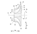
- the centrifugal multistage compressor includes a rotating shaft 10, a casing 20, a plurality of impellers 30, a radial bearing 11, and a thrust bearing 12.
- the rotary shaft 10 has a cylindrical shape with the axis line Ar as the center, and rotates about the axis line Ar.
- Both the radial bearing 11 and the thrust bearing 12 are fixed to the casing 20 and support the rotary shaft 10 in a rotatable manner.
- the plurality of impellers 30 are fixed to the outer peripheral side of the rotating shaft 10 along the axial direction Da in which the axis Ar extends.
- the plurality of impellers 30 rotate integrally with the rotary shaft 10 about the axis Ar.
- the impeller 30 includes a disk 31, a plurality of blades 35, and a cover 36.
- one side of the axial direction Da is defined as an axial front side Daf
- the other side of the axial direction Da is defined as an axial rear side Dab.
- the radial direction with respect to the axis Ar is simply the radial direction Dr
- the side closer to the axis Ar in the radial direction Dr is the radially inner side Dr
- the side away from the axis Ar in the radial direction Dr is the radially outer side Dro.
- the circumferential direction with respect to the axis Ar is simply referred to as a circumferential direction Dc.
- the diameter of the disk 31 is gradually increased from the axial front side Daf to the axial rear side Dab.
- the direction component toward the axial rear side Dab is larger than the component toward the radially outer side Dro.
- the direction component toward the radially outer side Dro is larger than the direction component toward the axial rear side Dab.
- the disk 31 is formed with a back surface 33 facing the axial rear side Dab. Further, the disk 31 is formed with a shaft hole 34 that penetrates the axis Ar in the axial direction Da. The rotating shaft 10 is attached to the shaft hole 34.
- the plurality of blades 35 are provided on the outer peripheral surface 32 of the disk 31 at intervals in the circumferential direction Dc.
- each blade 35 bends gradually toward the counter-rotating side with respect to the rotational direction of the impeller 30 as it goes from the radially inner portion Dri toward the radially outer side Dro.
- the cover 36 is disposed to face the outer peripheral surface 32 of the disk 31, and sandwiches a plurality of blades 35 with the disk 31.
- An inner peripheral surface 37 of the cover 36 faces the outer peripheral surface 32 of the disk 31.
- the direction component toward the axial rear side Dab is larger than the component toward the radially outer side Dro.
- the direction component toward the radially outer side Dro is larger than the direction component toward the axial rear side Dab.
- the cover 36 is formed with an outer peripheral surface 38 that is in a back-to-back relationship with the inner peripheral surface 37.
- an in-impeller flow path 41 is formed through which the fluid flowing in from the axial front Daf flows out to the radially outer side Dro. Therefore, the inlet 42 of the in-impeller flow path 41 opens toward the axially front side Daf. Further, the outlet 43 of the in-impeller channel 41 opens toward the radially outer side Dro.
- the in-impeller channel 41 is gradually bent from the inlet 42 of the in-impeller channel 41 toward the axially rear side Dab and radially outward Dro with respect to the axis Ar. Furthermore, when viewed from the axial direction Da, the in-impeller flow path 41 gradually bends in the direction opposite to the rotational direction of the impeller 30 from the inlet 42 of the impeller flow path 41 toward the radially outer side Dro. ing.
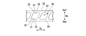
- the corners of the disk 31 and the blade 35 and the corners of the cover 36 and the disk 31 all form a fillet portion 39.
- the fillet portion 39 has a smooth concave shape from the inside to the outside of the in-impeller channel 41.
- the casing 20 covers the rotating shaft 10, the bearings 11 and 12, and the plurality of disks 31.
- a suction channel 21, a discharge channel 22, and an intermediate channel 23 are formed in the casing 20.
- the suction flow path 21 guides fluid from the outside into the in-impeller flow path 41 of the impeller 30 that is disposed on the frontmost axial direction Daf.
- the discharge flow path 22 guides the fluid from the impeller 30 arranged on the most axial rear side Dab to the outside.
- the intermediate flow path 23 allows the fluid flowing out from the outlet 43 of the one impeller 30 to flow from the inlet 42 of the other impeller 30 adjacent to the rear side Dab in the axial direction with respect to the one impeller 30 to the other impeller 30.
- the casing 20 of the centrifugal multistage compressor is prepared (S1: casing preparation step), and the impeller 30 of the centrifugal multistage compressor is prepared (S2: impeller preparation step).
- the rotary shaft 10, the bearings 11 and 12, and parts such as a shaft seal (not shown) are also prepared (S3: part preparation step).
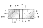
- a block larger than the outer shape of the impeller 30 is prepared (S10: block preparation step).
- the outer shape and the like of this block are cut to form the intermediate block 50 (S11: outer shape cutting step).
- the outer shape of the block is cut, and the region to be the shaft hole 34 in the block is also cut to form the shaft hole 34a.
- the shaft hole 34a may already be formed in the block.
- the outer shape cutting step (S11) for forming the intermediate block 50 from the blocks may not be performed.
- a region that becomes the impeller channel 41 of the impeller 30 is defined as a channel region 51.
- a region that becomes the inlet 42 of the in-impeller channel 41 is referred to as an inlet region 52, and a region that becomes the outlet 43 of the in-impeller channel 41 is referred to as an outlet region 53.
- the intermediate block 50 is cut, and the impeller channel 41 is formed in the intermediate block 50 (S12: channel cutting step).
- the intermediate block 50 is cut using at least three types of tools.
- Each of the tools has a tool body centered on the tool axis At and a blade is formed at least on the outer periphery, and the tool body is fixed, and the tool axis At extends in the tool axis direction Dta around the tool axis At. And a long handle.
- the first tool is a rough cutting tool 60a as shown in FIGS. 6A and 6B.
- the rough cutting tool 60a is, for example, a radius end mill.
- the rough cutting tool 60a has a tool body 61a and a handle 65a to which the tool body 61a is fixed.
- the tool main body 61a includes a columnar head 63a centering on the tool axis At1 and a plurality of tips 62a fixed to the outer periphery of the head 63a.
- the plurality of tips 62a are arranged in the circumferential direction with respect to the tool axis At1.
- Each tip 62a has a blade.
- this tool main body 61a may be one in which a head portion and a plurality of blade portions are integrated.
- the handle 65a has a shank 66a and a holder 67a.
- Each of the shank 66a and the holder 67a has a long column shape in the tool axis direction Dta in which the tool axis At1 extends with the tool axis At1 as the center.
- the shank 66a and the holder 67a each have a distal end and a proximal end that are ends in the tool axis direction Dta.
- the head 63a of the tool body 61a is fixed to the tip of the shank 66a.
- the proximal end of the shank 66a is attached to the distal end of the holder 67a.
- the base end 68a of the holder 67a is a portion chucked by the machine tool.
- the maximum outer diameter of the tool body 61a is Dt1.
- the shank outer diameter Ds1 is smaller than the minimum outer diameter of the holder 67a. Therefore, the shank outer diameter Ds1 is the minimum outer diameter of the handle 65a.
- the shank outer diameter Ds1, that is, the minimum outer diameter of the handle 65a is slightly smaller than the maximum outer diameter Dt1 of the tool body 61a.
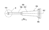
- the second tool is a medium / finishing cutting tool 60b as shown in FIGS. 7A and 7B.
- the middle / finishing cutting tool 60b is, for example, a ball end mill.
- the middle / finishing cutting tool 60b has a hemispherical tool body 61b centering on the tool axis At2 and a handle 65b to which the tool body 61b is fixed.
- a blade is formed on the hemispherical tool body 61b.
- the tool body 61b has a head and a plurality of chips attached to the head, like the tool body 61a of the rough cutting tool 60a.
- this tool main body 61b may also have an integrated head portion and a plurality of blade portions.
- the handle 65b has a shank 66b and a holder 67b.
- Each of the shank 66b and the holder 67b has a long column shape in the tool axis direction Dta in which the tool axis Atb extends with the tool axis At2 as the center.
- the shank 66b and the holder 67b each have a distal end and a proximal end that are ends in the tool axis direction Dta.
- a tool body 61b is fixed to the tip of the shank 66b.
- the base end of the shank 66b is attached to the tip of the holder 67b.
- the base end 68b of the holder 67b is a portion chucked by the machine tool.
- the maximum outer diameter of the tool body 61b is Dt2.
- the maximum outer diameter Dt2 of the tool body 61b is less than twice (2r) the concave radius of curvature r (see FIG. 3) in the fillet portion 39. That is, the maximum radius Dt2 of the tool body 61b is less than the concave curvature radius r of the fillet portion 39.
- the shank outer diameter Ds2 is smaller than the minimum outer diameter of the holder 67b. Therefore, the shank outer diameter Ds2 is the minimum outer diameter of the handle 65b.
- the shank outer diameter Ds2, that is, the minimum outer diameter of the handle 65b is slightly smaller than the maximum outer diameter Dt2 of the tool body 61b.
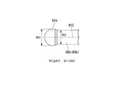
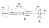
- the third tool is the remaining cutting tool 60c as shown in FIGS. 8A and 8B.
- the remaining cutting tool 60c is, for example, a lollipop mill.
- the remaining cutting tool 60c includes a tool body 61c having a spherical shape with the tool axis At3 as the center, and a handle 65c to which the tool body 61c is fixed.
- the sphere shape is a shape of a portion having a larger volume among the two portions by cutting the sphere along a plane that does not pass through the center of the sphere.
- a blade is formed on the outer periphery of the spherical tool body 61c.
- the tool body 61c Similar to the tool body 61a of the rough cutting tool 60a, the tool body 61c includes a head and a plurality of chips attached to the head. In addition, this tool main body 61c may also have an integrated head portion and a plurality of blade portions.
- the handle 65c has a shank 66c and a holder 67c. Both the shank 66c and the holder 67c have a long column shape in the tool axis direction Dta in which the tool axis Atb extends with the tool axis At3 as the center.
- the shank 66c and the holder 67c each have a distal end and a proximal end that are ends in the tool axis direction Dta.
- a tool body 61c is fixed to the tip of the shank 66c.
- the proximal end of the shank 66c is attached to the distal end of the holder 67c.
- the base end 68c of the holder 67c is a portion chucked by the machine tool.
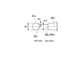
- the maximum outer diameter of the tool main body 61c is Dt3.
- the maximum outer diameter Dt3 of the tool body 61c is also less than twice (2r) the concave radius of curvature r (see FIG. 3) of the fillet portion 39, similar to the maximum outer diameter Dt2 of the tool body 61b described above. That is, the maximum radius Dt3 of the tool body 61c is also less than the concave curvature radius r of the fillet portion 39.
- the shank outer diameter Ds3 is smaller than the minimum outer diameter of the holder 67c. Therefore, the shank outer diameter Ds3 is the minimum outer diameter of the handle 65c.
- the shank outer diameter Ds3, that is, the minimum outer diameter of the handle 65c is smaller than the maximum outer diameter Dt3 of the tool body 61c.
- the dimensional relationship of the maximum outer diameter Dt of each tool body 61a, 61b, 61c is as follows. Dt1 ⁇ Dt2 ⁇ Dt3 Therefore, the maximum outer diameter Dt3 of the tool body 61c of the remaining cutting tool 60c is basically among the maximum outer diameters Dt1, Dt2, and Dt3 of the tool bodies 61a, 61b, and 61c of the three types of cutting tools 60a, 60b, and 60c. It becomes the minimum. However, the maximum outer diameter Dt3 of the tool main body 61c of the remaining cutting tool 60c may be the same as the maximum outer diameter Dt2 of the tool main body 61b of the medium / finishing cutting tool 60b.
- the dimensional relationship of the minimum outer diameter Ds of each handle 65a, 65b, 65c is as follows. Ds1 ⁇ Ds2> Ds3 Therefore, the minimum outer diameter Ds3 of the handle 65c of the remaining cutting tool 60c is the smallest among the minimum outer diameters Ds1, Ds2, and Ds3 of the handles 65a, 65b, and 65c of the three types of cutting tools 60a, 60b, and 60c.
- the overhang amount OH which is the distance to the position, is the maximum among the overhang amounts of the plurality of tools 60a, 60b, 60c.
- the overhang amount OH of the remaining cutting tool 60c is maximized is that the remaining cutting tool 60c is used for the drawing cutting.
- the tool is moved to the base end 68c side in the tool axis direction Dta, that is, the tool rear side Dtb (see FIG. 15) while rotating the remaining cutting tool 60c about the tool axis At3.
- the tool main body 61c of the remaining cutting tool 60c has the rear blade 62 facing in the direction including the tool rear side component. Therefore, the tool body 61c has a blade formed in a range of 200 ° or more, preferably in a range of 240 ° or more, in a virtual plane including the tool axis At3.
- the tool body 61c of the remaining cutting tool 60c described above has a notch shape in a virtual plane including the tool axis At3.
- the tool main body 61c of the remaining cutting tool 60c may have a shape in which a virtual plane including the tool axis At3 is cut out on one side of an elliptical short axis. Further, in the case of performing the drawing cutting process exclusively with the remaining cutting tool 60c, there may be no blade on the tip side of the tool body 61c of the remaining cutting tool 60c.
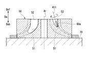
- the flow path region 51 in the intermediate block 50 is cut using the rough cutting tool 60a (S13: rough cutting step).
- the intermediate block 50 is set on the table 70 of the machine tool so that the axial rear side Dab of the intermediate block 50 faces downward.
- the rough cutting tool 60a is attached to the chuck of the machine tool.
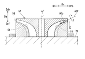
- the rough cutting tool 60a is inserted from the inlet region 52 in the intermediate block 50 toward the axial rear side Dab to cut the flow path region 51 in the intermediate block 50 (S13a).
- First rough cutting step In the first rough cutting step (S13a), the region on the inlet region 52 side in the flow channel region 51 is cut.
- the intermediate block 50 is placed on the table 70 of the machine tool so that the axial front Daf of the intermediate block 50 faces downward. Set up. Then, while rotating the rough cutting tool 60a, the rough cutting tool 60a is inserted from the outlet region 53 in the intermediate block 50 toward the radially inner side Dri to cut the flow path region 51 in the intermediate block 50 (S13b: Second rough cutting process). In the second rough cutting step (S13b), the area on the outlet area 53 side in the flow path area 51 is cut.
- the remaining part in the rough cutting step (S13) in the flow channel region 51 is cut using the medium / finish cutting tool 60b (S14: medium / finish cutting step).
- the middle / finishing cutting tool 60b is attached to the chuck of the machine tool.
- the intermediate block 50 remains in the state of the second rough cutting process (S13b), that is, remains set on the table 70 of the machine tool so that the axial front side Daf faces downward.
- the middle / finishing cutting tool 60b is inserted from the outlet region 53 in the intermediate block 50 toward the radially inner side Dri to cut the flow path region 51 in the intermediate block 50.
- S14a first medium / finish cutting step.
- the region on the outlet region 53 side is cut out of the portion remaining in the rough cutting step (S13) in the flow channel region 51.
- the intermediate block 50 is moved so that the axial rear side Dab of the intermediate block 50 faces downward.
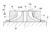
- the middle / finishing cutting tool 60b is inserted from the inlet region 52 in the intermediate block 50 toward the axial rear side Dab, and the flow path region 51 in the intermediate block 50 is set.
- Cutting is performed (S14b: second medium / finish cutting step).
- the region on the inlet region 52 side of the portion remaining in the rough cutting step (S13) in the flow path region 51 is cut.
- the tools 60a and 60b are inserted from the entrance region 52 of the intermediate block 50 toward the axial rear side Dab to cut the intermediate block 50.
- Performing the steps (S13a, S14b) and the steps (S13b, S14a) of cutting the intermediate block 50 by inserting the tools 60a, 60b from the outlet region 53 of the intermediate block 50 toward the radially inner side Dri.
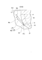
- the radius of curvature of the in-impeller channel 41 is relatively small with respect to the opening area of the inlet 42 and the outlet 43, the channel region 51 may not be completely cut. Specifically, as shown in FIGS.
- the radius of curvature of the inner peripheral surface 37 of the cover 36 is larger than the radius of curvature of the outer peripheral surface 32 of the disk 31 among the surfaces defining the flow path 41 in the impeller. Therefore, in the inner peripheral surface 37 of the cover 36, an uncut portion 55 that cannot be cut by the rough cutting step (S13) and the middle / finishing cutting step (S14) at the intermediate portion between the inlet 42 and the outlet 43 is provided. May occur. Therefore, in the present embodiment, the remaining cutting step (S15) is executed after the middle / finishing cutting step (S14).
- the remaining cutting tool 60c is attached to the chuck of the machine tool.
- the intermediate block 50 remains in the state of the second middle / finishing cutting step (S14b), that is, remains set on the table 70 of the machine tool such that the axial rear side Dab faces downward.
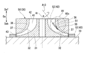
- the remaining cutting tool 60 c is inserted from the inlet region 52 in the intermediate block 50 toward the axial rear side Dab, and the above-described cutting residual is performed in the flow path region 51 in the intermediate block 50.
- 55 is cut (S15a: first remaining cutting step).
- the remaining cutting tool 60c is reciprocated in the direction in which the tool axis At3 extends to cut the remaining cutting 55. That is, here, the pulling cutting process and the butt cutting process by the remaining cutting tool 60c are alternately repeated.
- the remaining cutting tool 60c is moved in the direction including the tool rear side Dtb component, and the remaining cutting 55 is cut by the rear blade 62 of the remaining cutting tool 60c.
- the tool body 61c of the remaining cutting tool 60c has the largest overhang amount OH among the three tools 60a, 60b, and 60c. Therefore, the remaining cutting tool 55 on the inner peripheral surface 37 of the cover 36 having a small curvature radius can be drawn and cut by the remaining cutting tool 60c. Further, as described above, the remaining cutting tool 60c basically has the smallest maximum outer diameter Dt3 of the tool body 61c among the three tools 60a, 60b, and 60c. For this reason, the fillet part 39 of the impeller 30 can also be cut.
- the intermediate block 50 is placed on the table 70 of the machine tool so that the axial front Daf of the intermediate block 50 faces downward. Set up. Then, while rotating the remaining cutting tool 60c, the remaining cutting tool 60c is inserted from the outlet region 53 in the intermediate block 50 toward the radially inner side Dri, and the remaining cutting tool 55 in the flow channel region 51 in the intermediate block 50 is cut. (S15b: second remaining cutting step). Also at this time, the remaining cutting tool 60c is reciprocated in the direction in which the tool axis At3 extends to cut the remaining cutting 55.
- the intermediate block 50 is further processed (S16: finishing step) to complete the impeller 30.
- finishing step (S16) heat treatment is performed on the intermediate block 50 in which the in-impeller channel 41 is formed, as necessary.
- the outer periphery and the like of the intermediate block 50 are cut to form the outer peripheral surface 38 of the cover 36 and the rear surface 33 of the disk 31.
- the portion of the intermediate block 50 where the shaft hole 34 a is formed is cut to form the shaft hole 34.
- the remaining cutting tool 60c is used.
- the in-impeller channel 41 can be formed in the intermediate block 50.
- the intermediate block 50 is cut using the rough cutting tool 60a and the medium / finish cutting tool 60b in addition to the remaining cutting tool 60c, the cutting efficiency of the flow path region 51 can be increased.
- the first middle / finishing cutting step (S14a) is performed without resetting the intermediate block 50 on the table 70 of the machine tool. Further, after the first middle / finishing cutting step (S14a), the first remaining cutting step (S15a) is executed without setting the intermediate block 50 on the table 70 of the machine tool. Therefore, the trouble of setting the intermediate block 50 can be omitted.
- the intermediate block 50 may be set in the opposite direction. Specifically, in the first rough cutting step (S ⁇ b> 13 a), the rough cutting tool 60 a is inserted from the exit region 53 of the intermediate block 50 with the axial front Daf in the intermediate block 50 facing downward. In the second rough cutting step (S13b), the intermediate block 50 is set so that the axial rear side Dab faces downward, and the rough cutting tool 60a is inserted from the entrance region 52 of the intermediate block 50.
- the medium / finish cutting tool 60b is inserted from the inlet region 52 of the intermediate block 50 while the axial rear side Dab of the intermediate block 50 is set downward.
- the intermediate block 50 is set so that the axial front side Daf of the intermediate block 50 faces downward, and the intermediate / finish cutting tool 60b is inserted from the outlet region 53 of the intermediate block 50.
- the remaining cutting tool 60c is inserted from the exit region 53 of the intermediate block 50 while being set so that the axial front Daf in the intermediate block 50 faces downward.
- the remaining cutting tool 60c uses a lollipop mill in which a blade is formed in a range of 240 ° or more in a virtual plane including the tool axis At3. However, when only the drawing cutting process is performed in the remaining cutting step (S15), as described above, there may be no blade on the tip side of the tool body 61c of the remaining cutting tool 60c.
- the rough cutting step (S13) using the rough cutting tool 60a the middle / finishing cutting step (S14) using the medium / finishing cutting tool 60b, and the remaining cutting step (S15) using the remaining cutting tool 60c.
- the intermediate / finish cutting step (S14) may be omitted.
- the above embodiment is a method of manufacturing the impeller 30 of the centrifugal multistage compressor.
- the present invention does not require the centrifugal rotating machine to have multiple stages, and may be a single stage.
- the present invention is not limited to the impeller 30 of the centrifugal compressor.
- the block for manufacturing the impeller A flow path can be formed even when the radius of curvature of the flow path of the closed-type impeller is relatively small with respect to the opening area of the inlet and the outlet.
Landscapes
- Engineering & Computer Science (AREA)
- Mechanical Engineering (AREA)
- General Engineering & Computer Science (AREA)
- Structures Of Non-Positive Displacement Pumps (AREA)
Abstract
Description
軸線を中心として円板状のディスクと、前記ディスクの外周面上に、前記軸線に対する周方向に互いに離間して設けられている複数のブレードと、前記ディスクとの間で複数の前記ブレードを挟み込むカバーと、を有し、前記ディスクと前記カバーとの相互間であって複数の前記ブレードの相互間に、前記軸線が延びる軸方向の一方側である軸方向前側から流入した流体を前記軸線に対する径方向外側に流出させる流路が形成されている、遠心式回転機械のインペラを一のブロックから形成するインペラの製造方法である。このインペラの製造方法は、互いに種類の異なる複数の工具を用いて、前記ブロック中で前記流路になる流路領域を切削する流路切削工程を実行し、前記流路切削工程は、複数の前記工具のうちの一工具である粗切削工具を用いて切削する粗切削工程と、複数の前記工具のうちの一工具である残り切削工具を用いて前記粗切削工程での切削残りを切削する残り切削工程と、を含み、前記流路切削工程で用いる複数の前記工具は、いずれも、工具軸線を中心とし、少なくとも外周に刃が形成されている工具本体と、前記工具本体が固定されて、前記工具軸線を中心して前記工具軸線が延びる工具軸方向に長い柄と、を有し、前記残り切削工具における前記工具本体の最大外径は、前記残り切削工具における前記柄の最小外径よりも大きく、前記残り切削工具における前記工具本体は、前記残り切削工具における前記工具本体に対する前記柄の側である工具後側成分を含む方向に向いている後刃を有する。
前記第一態様の前記インペラの製造方法において、前記残り切削工程では、前記残り切削工具を回転させつつ、前記工具後側成分を含む方向に前記残り切削工具を移動させて、前記残り切削工具の前記後刃で、前記粗切削工程での切削残りを切削する工程を含む。
前記第一又は前記第二態様の前記インペラの製造方法において、前記工具軸線に対して垂直な方向で、前記柄の最小外径となる位置での外周面から前記工具本体の外周のうちで最大外径になる位置までの距離である張出量は、複数の前記工具のうちで、前記残り切削工具が最大である。
前記第一から前記第三態様のうちのいずれかの前記インペラの製造方法において、前記柄の最小外径は、複数の前記工具のうちで、前記残り切削工具が最少である。
前記第一から前記第四態様のうちのいずれかの前記インペラの製造方法において、前記工具本体の最大外径は、複数の前記工具のうちで、前記残り切削工具が最少である。
前記第一から前記第五態様のうちのいずれかの前記インペラの製造方法において、前記残り切削工具の前記工具本体は、前記工具軸線を含む仮想平面内で、200°以上の範囲で前記刃が形成されている。
前記第一から前記第六態様のうちのいずれかの前記インペラの製造方法において、前記残り切削工具の前記工具本体は、前記工具軸線を含む仮想平面内で、240°以上の範囲で前記刃が形成されている。
前記第一から前記第七態様のうちのいずれかの前記インペラの製造方法において、前記流路切削工程は、前記粗切削工程後に、複数の前記工具のうちの一工具である中/仕上切削工具を用いて前記粗切削工程での切削残りを切削する中/仕上切削工程を含み、前記残り切削工程は、前記中/仕上切削工程後に、前記中/仕上切削工程での切削残りを切削する。
前記第八態様の前記インペラの製造方法において、前記中/仕上切削工具における前記柄の前記先端部の外径は、前記粗切削工具における前記柄の前記先端部の外径以下である。
前記第八又は前記第九態様の前記インペラの製造方法において、前記中/仕上切削工具における前記工具本体の最大外径は、前記粗切削工具における前記工具本体の最大外径以下である。
前記第八から前記第十態様のうちのいずれかの前記インペラの製造方法において、前記粗切削工程は、前記インペラで前記流体が流入する入口になる前記ブロック中の入口領域と前記インペラで前記流体が流出する出口になる前記ブロック中の出口領域とのうち、一方の領域から前記ブロック内に前記粗切削工具を入れて前記流路領域を切削する第一粗切削工程と、前記第一粗切削工程後に、前記出口領域と前記入口領域とのうち、他方の領域から前記ブロック内に前記粗切削工具を入れて前記流路領域を切削する第二粗切削工程と、を含み、前記中/仕上切削工程は、前記第二粗切削工程後に、前記ブロック中の前記他方の領域から前記ブロック内に前記中/仕上切削工具を入れて、前記流路領域を切削する第一中/仕上切削工程と、前記第一中/仕上切削工程後に、前記ブロック中の前記一方の領域から前記ブロック内に前記中/仕上切削工具を入れて、前記流路領域を切削する第二中/仕上切削工程と、を含み、前記残り切削工程は、前記第二中/仕上切削工程後に、前記ブロック中の前記一方の領域から前記ブロック内に前記残り切削工具を入れて、前記流路領域を切削する第一残り切削工程を含む。
前記第八から前記第十一態様のうちのいずれかの前記インペラの製造方法において、前記中/仕上切削工具は、ボールエンドミルである。
前記第一から前記第十二態様のうちのいずれかの前記インペラの製造方法において、前記粗切削工具は、ラジアスエンドミルである。
前記第一から前記第十三態様のうちのいずれかの前記インペラの製造方法において、前記残り切削工具は、ロリポップミルである。
前記第一から前記第十四態様のうちのいずれかの前記インペラの製造方法を実行すると共に、前記インペラが装着され、前記軸線を中心とする回転軸と、前記インペラを覆うケーシングとを含む部品を準備する準備工程と、前記インペラと、前記回転軸及び前記ケーシングを含む前記部品とを組み合わせる組立工程と、を実行する。
Dt1≧Dt2≧Dt3
よって、残り切削工具60cの工具本体61cの最大外径Dt3は、基本的に、三種類の切削工具60a,60b,60cの工具本体61a,61b,61cの最大外径Dt1,Dt2,Dt3のうちで最少になる。但し、残り切削工具60cの工具本体61cの最大外径Dt3は、中/仕上切削工具60bの工具本体61bの最大外径Dt2と同じであってもよい。
Ds1≧Ds2>Ds3
よって、残り切削工具60cの柄65cの最小外径Ds3は、三種類の切削工具60a,60b,60cの柄65a,65b,65cの最小外径Ds1,Ds2,Ds3のうちで最少になる。
11:ラジアル軸受
12:スラスト軸受
20:ケーシング
21:吸込流路
22:吐出流路
23:中間流路
30:インペラ
31:ディスク
32:外周面
33:背面
34,34a:軸孔
35:ブレード
36:カバー
37:内周面
38:外周面
39:フィレット部
41:インペラ内流路
42:入口
43:出口
50:中間ブロック
51:流路領域
52:入口領域
53:出口領域
55:切削残り
60a:粗切削工具
60b:中/仕上切削工具
60c:残り切削工具
61a,61b,61c:工具本体
62:後刃
65a,65b,65c:柄
66a,66b,66c:シャンク
67a,67b,67c:ホルダ
68a,68b,68c:基端
70:テーブル
Ar:軸線
At1,At2,At3:工具軸線
Da:軸方向
Dab:軸方向後側
Daf:軸方向前側
Dc:周方向
Dr:径方向
Dri:径方向内側
Dro:径方向外側
Dta:工具軸方向
Dtb:工具後側
OH:張出量
Claims (15)
- 軸線を中心として円板状のディスクと、前記ディスクの外周面上に、前記軸線に対する周方向に互いに離間して設けられている複数のブレードと、前記ディスクとの間で複数の前記ブレードを挟み込むカバーと、を有し、前記ディスクと前記カバーとの相互間であって複数の前記ブレードの相互間に、前記軸線が延びる軸方向の一方側である軸方向前側から流入した流体を前記軸線に対する径方向外側に流出させる流路が形成されている、遠心式回転機械のインペラを一のブロックから形成するインペラの製造方法において、
互いに種類の異なる複数の工具を用いて、前記ブロック中で前記流路になる流路領域を切削する流路切削工程を実行し、
前記流路切削工程は、複数の前記工具のうちの一工具である粗切削工具を用いて切削する粗切削工程と、複数の前記工具のうちの一工具である残り切削工具を用いて前記粗切削工程での切削残りを切削する残り切削工程と、を含み、
前記流路切削工程で用いる複数の前記工具は、いずれも、工具軸線を中心とし、少なくとも外周に刃が形成されている工具本体と、前記工具本体が固定されて、前記工具軸線を中心して前記工具軸線が延びる工具軸方向に長い柄と、を有し、
前記残り切削工具における前記工具本体の最大外径は、前記残り切削工具における前記柄の最小外径よりも大きく、前記残り切削工具における前記工具本体は、前記残り切削工具における前記工具本体に対する前記柄の側である工具後側成分を含む方向に向いている後刃を有する、
インペラの製造方法。 - 請求項1に記載のインペラの製造方法において、
前記残り切削工程では、前記残り切削工具を回転させつつ、前記工具後側成分を含む方向に前記残り切削工具を移動させて、前記残り切削工具の前記後刃で、前記粗切削工程での切削残りを切削する工程を含む、
インペラの製造方法。 - 請求項1又は2に記載のインペラの製造方法において、
前記工具軸線に対して垂直な方向で、前記柄の最小外径になる位置での外周面から前記工具本体の外周のうちで最大外径になる位置までの距離である張出量は、複数の前記工具のうちで、前記残り切削工具が最大である、
インペラの製造方法。 - 請求項1から3のいずれか一項に記載のインペラの製造方法において、
前記柄の最小外径は、複数の前記工具のうちで、前記残り切削工具が最少である、
インペラの製造方法。 - 請求項1から4のいずれか一項に記載のインペラの製造方法において、
前記工具本体の最大外径は、複数の前記工具のうちで、前記残り切削工具が最少である、
インペラの製造方法。 - 請求項1から5のいずれか一項に記載のインペラの製造方法において、
前記残り切削工具の前記工具本体は、前記工具軸線を含む仮想平面内で、200°以上の範囲で前記刃が形成されている、
インペラの製造方法。 - 請求項1から6のいずれか一項に記載のインペラの製造方法において、
前記残り切削工具の前記工具本体は、前記工具軸線を含む仮想平面内で、240°以上の範囲で前記刃が形成されている、
インペラの製造方法。 - 請求項1から7のいずれか一項に記載のインペラの製造方法において、
前記流路切削工程は、前記粗切削工程後に、複数の前記工具のうちの一工具である中/仕上切削工具を用いて前記粗切削工程での切削残りを切削する中/仕上切削工程を含み、
前記残り切削工程は、前記中/仕上切削工程後に、前記中/仕上切削工程での切削残りを切削する、
インペラの製造方法。 - 請求項8に記載のインペラの製造方法において、
前記中/仕上切削工具における前記柄の最小外径は、前記粗切削工具における前記柄の最小外径以下である、
インペラ30の製造方法。 - 請求項8又は9に記載のインペラの製造方法において、
前記中/仕上切削工具における前記工具本体の最大外径は、前記粗切削工具における前記工具本体の最大外径以下である、
インペラの製造方法。 - 請求項8から10のいずれか一項に記載のインペラの製造方法において、
前記粗切削工程は、
前記インペラで前記流体が流入する入口になる前記ブロック中の入口領域と前記インペラで前記流体が流出する出口になる前記ブロック中の出口領域とのうち、一方の領域から前記ブロック内に前記粗切削工具を入れて前記流路領域を切削する第一粗切削工程と、
前記第一粗切削工程後に、前記出口領域と前記入口領域とのうち、他方の領域から前記ブロック内に前記粗切削工具を入れて前記流路領域を切削する第二粗切削工程と、を含み、
前記中/仕上切削工程は、
前記第二粗切削工程後に、前記ブロック中の前記他方の領域から前記ブロック内に前記中/仕上切削工具を入れて、前記流路領域を切削する第一中/仕上切削工程と、
前記第一中/仕上切削工程後に、前記ブロック中の前記一方の領域から前記ブロック内に前記中/仕上切削工具を入れて、前記流路領域を切削する第二中/仕上切削工程と、を含み、
前記残り切削工程は、
前記第二中/仕上切削工程後に、前記ブロック中の前記一方の領域から前記ブロック内に前記残り切削工具を入れて、前記流路領域を切削する第一残り切削工程を含む、
インペラの製造方法。 - 請求項8から11のいずれか一項に記載のインペラの製造方法において、
前記中/仕上切削工具は、ボールエンドミルである、
インペラの製造方法。 - 請求項1から12のいずれか一項に記載のインペラの製造方法において、
前記粗切削工具は、ラジアスエンドミルである、
インペラの製造方法。 - 請求項1から13のいずれか一項に記載のインペラの製造方法において、
前記残り切削工具は、ロリポップミルである、
インペラの製造方法。 - 請求項1から14のいずれか一項に記載の前記インペラの製造方法を実行すると共に、
前記インペラが装着され、前記軸線を中心とする回転軸と、前記インペラを覆うケーシングとを含む部品を準備する準備工程と、
前記インペラと、前記回転軸及び前記ケーシングを含む前記部品とを組み合わせる組立工程と、
を実行する遠心式回転機械の製造方法。
Priority Applications (4)
| Application Number | Priority Date | Filing Date | Title |
|---|---|---|---|
| EP16915209.7A EP3421809B1 (en) | 2016-09-05 | 2016-09-05 | Method for manufacturing centrifugal rotary machine and method for manufacturing impeller therefor |
| JP2018536661A JP6672466B2 (ja) | 2016-09-05 | 2016-09-05 | 遠心式回転機械の製造方法、及びそのインペラの製造方法 |
| PCT/JP2016/075979 WO2018042653A1 (ja) | 2016-09-05 | 2016-09-05 | 遠心式回転機械の製造方法、及びそのインペラの製造方法 |
| US16/089,109 US10994347B2 (en) | 2016-09-05 | 2016-09-05 | Method for manufacturing centrifugal rotary machine and method for manufacturing impeller thereof |
Applications Claiming Priority (1)
| Application Number | Priority Date | Filing Date | Title |
|---|---|---|---|
| PCT/JP2016/075979 WO2018042653A1 (ja) | 2016-09-05 | 2016-09-05 | 遠心式回転機械の製造方法、及びそのインペラの製造方法 |
Publications (1)
| Publication Number | Publication Date |
|---|---|
| WO2018042653A1 true WO2018042653A1 (ja) | 2018-03-08 |
Family
ID=61300263
Family Applications (1)
| Application Number | Title | Priority Date | Filing Date |
|---|---|---|---|
| PCT/JP2016/075979 Ceased WO2018042653A1 (ja) | 2016-09-05 | 2016-09-05 | 遠心式回転機械の製造方法、及びそのインペラの製造方法 |
Country Status (4)
| Country | Link |
|---|---|
| US (1) | US10994347B2 (ja) |
| EP (1) | EP3421809B1 (ja) |
| JP (1) | JP6672466B2 (ja) |
| WO (1) | WO2018042653A1 (ja) |
Cited By (3)
| Publication number | Priority date | Publication date | Assignee | Title |
|---|---|---|---|---|
| CN110695422A (zh) * | 2019-11-11 | 2020-01-17 | 苏州千机智能技术有限公司 | 一种闭式整体叶盘型腔固定轴铣削加工方法 |
| CN113446260A (zh) * | 2020-03-27 | 2021-09-28 | 三菱重工压缩机有限公司 | 叶轮以及离心压缩机 |
| US12358059B2 (en) | 2020-03-31 | 2025-07-15 | Makino Milling Machine Co., Ltd. | Cutting tool and method for machining workpiece |
Families Citing this family (1)
| Publication number | Priority date | Publication date | Assignee | Title |
|---|---|---|---|---|
| CN117124101B (zh) * | 2023-08-30 | 2026-04-28 | 鑫磊压缩机股份有限公司 | 一种三元流叶轮加工工装及加工方法 |
Citations (6)
| Publication number | Priority date | Publication date | Assignee | Title |
|---|---|---|---|---|
| US2396488A (en) * | 1943-05-20 | 1946-03-12 | Bristol Aeroplane Co Ltd | Milling or like machine |
| JP2004009158A (ja) * | 2002-06-04 | 2004-01-15 | Sumitomo Rubber Ind Ltd | ゴルフボール用金型の製造方法 |
| JP2008509012A (ja) * | 2004-08-03 | 2008-03-27 | エシロール アンテルナシオナル (コンパニー ジェネラレ ドプテイク) | 眼科用レンズのラスタ切削技術 |
| JP2010269416A (ja) * | 2009-05-22 | 2010-12-02 | Noda Kanagata Kk | 削り出しエルボの製造方法 |
| JP2014040838A (ja) | 2002-09-03 | 2014-03-06 | Nuovo Pignone Holding Spa | 遠心圧縮機のロータの改良された製造方法 |
| JP2015226953A (ja) * | 2014-05-31 | 2015-12-17 | 三菱日立ツール株式会社 | 小径エンドミル |
Family Cites Families (15)
| Publication number | Priority date | Publication date | Assignee | Title |
|---|---|---|---|---|
| US2480807A (en) * | 1944-11-18 | 1949-08-30 | Thompson Prod Inc | Method of and apparatus for making impeller wheels |
| US5438755A (en) * | 1993-11-17 | 1995-08-08 | Giberson; Melbourne F. | Method of making a monolithic shrouded impeller |
| US6077002A (en) | 1998-10-05 | 2000-06-20 | General Electric Company | Step milling process |
| FR2828824B1 (fr) | 2001-08-23 | 2003-12-05 | Snecma Moteurs | Procede de fabrication d'un disque aubage monobloc de rotor et disque correspondant |
| US6760971B2 (en) * | 2002-07-15 | 2004-07-13 | Pratt & Whitney Canada Corp. | Method of making a gas turbine engine diffuser |
| KR101093461B1 (ko) * | 2002-12-26 | 2011-12-13 | 미쓰비시 마테리알 가부시키가이샤 | 레디어스 엔드밀 |
| JP4242411B2 (ja) * | 2006-11-02 | 2009-03-25 | シグマ株式会社 | インペラ |
| WO2011125080A1 (en) * | 2010-04-09 | 2011-10-13 | Gr-Servizi S.R.L. | Process for producing metallic shaped articles |
| US8826784B2 (en) * | 2011-08-29 | 2014-09-09 | United Technologies Corporation | Airfoil machining method and cutting tools |
| JP2013047479A (ja) * | 2011-08-29 | 2013-03-07 | Mitsubishi Heavy Ind Ltd | インペラ及びこれを備えた回転機械並びにインペラの製造方法 |
| US9381615B2 (en) * | 2012-05-03 | 2016-07-05 | Pratt & Whitney Canada Corp. | Method of machining surfaces of rotor disc and grinding machine therefor |
| DE102012009038A1 (de) * | 2012-05-04 | 2013-11-07 | Hufschmied Zerspanungssysteme Gmbh | Fräser und Fräsverfahren |
| EP2915616B1 (en) * | 2012-10-31 | 2019-01-16 | Makino Milling Machine Co., Ltd. | Rib-machining method |
| US8858128B2 (en) * | 2012-11-14 | 2014-10-14 | Iscar, Ltd. | Corner radius end mill |
| US10821520B2 (en) * | 2017-02-24 | 2020-11-03 | Mitsubishi Heavy Industries Compressor Corporation | Production method for impeller |
-
2016
- 2016-09-05 US US16/089,109 patent/US10994347B2/en active Active
- 2016-09-05 WO PCT/JP2016/075979 patent/WO2018042653A1/ja not_active Ceased
- 2016-09-05 JP JP2018536661A patent/JP6672466B2/ja active Active
- 2016-09-05 EP EP16915209.7A patent/EP3421809B1/en active Active
Patent Citations (7)
| Publication number | Priority date | Publication date | Assignee | Title |
|---|---|---|---|---|
| US2396488A (en) * | 1943-05-20 | 1946-03-12 | Bristol Aeroplane Co Ltd | Milling or like machine |
| JP2004009158A (ja) * | 2002-06-04 | 2004-01-15 | Sumitomo Rubber Ind Ltd | ゴルフボール用金型の製造方法 |
| JP2014040838A (ja) | 2002-09-03 | 2014-03-06 | Nuovo Pignone Holding Spa | 遠心圧縮機のロータの改良された製造方法 |
| JP2015206368A (ja) * | 2002-09-03 | 2015-11-19 | ヌオーヴォ ピニォーネ ホールディング ソシエタ ペル アチオニNuovo Pignone Holding S.p.A. | 遠心圧縮機のロータの改良された製造方法 |
| JP2008509012A (ja) * | 2004-08-03 | 2008-03-27 | エシロール アンテルナシオナル (コンパニー ジェネラレ ドプテイク) | 眼科用レンズのラスタ切削技術 |
| JP2010269416A (ja) * | 2009-05-22 | 2010-12-02 | Noda Kanagata Kk | 削り出しエルボの製造方法 |
| JP2015226953A (ja) * | 2014-05-31 | 2015-12-17 | 三菱日立ツール株式会社 | 小径エンドミル |
Cited By (8)
| Publication number | Priority date | Publication date | Assignee | Title |
|---|---|---|---|---|
| CN110695422A (zh) * | 2019-11-11 | 2020-01-17 | 苏州千机智能技术有限公司 | 一种闭式整体叶盘型腔固定轴铣削加工方法 |
| CN113446260A (zh) * | 2020-03-27 | 2021-09-28 | 三菱重工压缩机有限公司 | 叶轮以及离心压缩机 |
| EP3885580A1 (en) | 2020-03-27 | 2021-09-29 | Mitsubishi Heavy Industries Compressor Corporation | Impeller and centrifugal compressor |
| JP2021156223A (ja) * | 2020-03-27 | 2021-10-07 | 三菱重工コンプレッサ株式会社 | インペラ、及び遠心圧縮機 |
| US11401944B2 (en) | 2020-03-27 | 2022-08-02 | Mitsubishi Heavy Industries Compressor Corporation | Impeller and centrifugal compressor |
| CN113446260B (zh) * | 2020-03-27 | 2023-11-21 | 三菱重工压缩机有限公司 | 叶轮以及离心压缩机 |
| JP7591871B2 (ja) | 2020-03-27 | 2024-11-29 | 三菱重工コンプレッサ株式会社 | 遠心圧縮機用のインペラ、及び遠心圧縮機 |
| US12358059B2 (en) | 2020-03-31 | 2025-07-15 | Makino Milling Machine Co., Ltd. | Cutting tool and method for machining workpiece |
Also Published As
| Publication number | Publication date |
|---|---|
| JPWO2018042653A1 (ja) | 2019-02-07 |
| US10994347B2 (en) | 2021-05-04 |
| EP3421809A4 (en) | 2019-05-08 |
| JP6672466B2 (ja) | 2020-03-25 |
| EP3421809B1 (en) | 2020-05-27 |
| US20190126364A1 (en) | 2019-05-02 |
| EP3421809A1 (en) | 2019-01-02 |
Similar Documents
| Publication | Publication Date | Title |
|---|---|---|
| US9903385B2 (en) | Impeller, rotary machine including the same, and method for manufacturing impeller | |
| JP5118649B2 (ja) | インペラ | |
| JP6672466B2 (ja) | 遠心式回転機械の製造方法、及びそのインペラの製造方法 | |
| EP1930121B1 (en) | Method of machining turbine airfoils by disc tools | |
| CN107249816B (zh) | 主轴装置 | |
| RU2493951C2 (ru) | Способ изготовления моноблочного лопаточного диска с кольцом для временного удержания лопаток, удаляемым перед этапом чистовой обработки фрезерованием | |
| RU2493950C2 (ru) | Способ изготовления моноблочного лопаточного диска с кольцом для временного удержания лопаток, удаляемым после этапа чистовой обработки фрезерованием | |
| JP5406812B2 (ja) | 遠心式流体機械用ロータ | |
| JP5606358B2 (ja) | インペラ及びこれを備えたロータ並びにインペラの製造方法 | |
| RU2492984C2 (ru) | Способ изготовления моноблочного лопаточного диска с кольцом для временного удержания лопаток | |
| JP5525610B2 (ja) | アブレイシブウォータージェットによる一体型羽根付きディスクの最適な製造プロセス | |
| JP5526234B2 (ja) | アブレイシブウォータージェットによる一体型羽根付きディスクの最適な製造プロセス | |
| JP2010121612A (ja) | インペラ、圧縮機およびインペラの製造方法 | |
| US7114255B2 (en) | Method of making a gas turbine engine diffuser | |
| JP2004036444A (ja) | シュラウド付インペラーの製造方法 | |
| JP2016191311A (ja) | インペラ、及び遠心圧縮機 | |
| EP3693608B1 (en) | Method of manufacturing centrifugal rotary machine and centrifugal rotary machine | |
| US20190376391A1 (en) | Impeller, rotary machine, method for manufacturing impeller, and method for manufacturing rotary machine | |
| JP6202731B2 (ja) | インペラの組立方法 | |
| JP6434739B2 (ja) | タービンロータ軸、及びタービンロータ軸の製造方法 | |
| JP2018168760A (ja) | インペラの製造方法、インペラ、及び、回転機械 | |
| HK1139099A1 (en) | Method for the production of a circular saw blade having a cooling channel | |
| HK1139099B (en) | Method for the production of a circular saw blade having a cooling channel |
Legal Events
| Date | Code | Title | Description |
|---|---|---|---|
| WWE | Wipo information: entry into national phase |
Ref document number: 2018536661 Country of ref document: JP Ref document number: 2016915209 Country of ref document: EP |
|
| ENP | Entry into the national phase |
Ref document number: 2016915209 Country of ref document: EP Effective date: 20180925 |
|
| 121 | Ep: the epo has been informed by wipo that ep was designated in this application |
Ref document number: 16915209 Country of ref document: EP Kind code of ref document: A1 |
|
| NENP | Non-entry into the national phase |
Ref country code: DE |