WO2018042499A1 - 車両制御装置 - Google Patents
車両制御装置 Download PDFInfo
- Publication number
- WO2018042499A1 WO2018042499A1 PCT/JP2016/075234 JP2016075234W WO2018042499A1 WO 2018042499 A1 WO2018042499 A1 WO 2018042499A1 JP 2016075234 W JP2016075234 W JP 2016075234W WO 2018042499 A1 WO2018042499 A1 WO 2018042499A1
- Authority
- WO
- WIPO (PCT)
- Prior art keywords
- vehicle
- speed
- upper limit
- allowable upper
- limit value
- Prior art date
Links
Images


Classifications
-
- B—PERFORMING OPERATIONS; TRANSPORTING
- B60—VEHICLES IN GENERAL
- B60W—CONJOINT CONTROL OF VEHICLE SUB-UNITS OF DIFFERENT TYPE OR DIFFERENT FUNCTION; CONTROL SYSTEMS SPECIALLY ADAPTED FOR HYBRID VEHICLES; ROAD VEHICLE DRIVE CONTROL SYSTEMS FOR PURPOSES NOT RELATED TO THE CONTROL OF A PARTICULAR SUB-UNIT
- B60W30/00—Purposes of road vehicle drive control systems not related to the control of a particular sub-unit, e.g. of systems using conjoint control of vehicle sub-units, or advanced driver assistance systems for ensuring comfort, stability and safety or drive control systems for propelling or retarding the vehicle
- B60W30/08—Active safety systems predicting or avoiding probable or impending collision or attempting to minimise its consequences
- B60W30/09—Taking automatic action to avoid collision, e.g. braking and steering
-
- B—PERFORMING OPERATIONS; TRANSPORTING
- B60—VEHICLES IN GENERAL
- B60W—CONJOINT CONTROL OF VEHICLE SUB-UNITS OF DIFFERENT TYPE OR DIFFERENT FUNCTION; CONTROL SYSTEMS SPECIALLY ADAPTED FOR HYBRID VEHICLES; ROAD VEHICLE DRIVE CONTROL SYSTEMS FOR PURPOSES NOT RELATED TO THE CONTROL OF A PARTICULAR SUB-UNIT
- B60W30/00—Purposes of road vehicle drive control systems not related to the control of a particular sub-unit, e.g. of systems using conjoint control of vehicle sub-units, or advanced driver assistance systems for ensuring comfort, stability and safety or drive control systems for propelling or retarding the vehicle
- B60W30/08—Active safety systems predicting or avoiding probable or impending collision or attempting to minimise its consequences
- B60W30/095—Predicting travel path or likelihood of collision
-
- B—PERFORMING OPERATIONS; TRANSPORTING
- B60—VEHICLES IN GENERAL
- B60W—CONJOINT CONTROL OF VEHICLE SUB-UNITS OF DIFFERENT TYPE OR DIFFERENT FUNCTION; CONTROL SYSTEMS SPECIALLY ADAPTED FOR HYBRID VEHICLES; ROAD VEHICLE DRIVE CONTROL SYSTEMS FOR PURPOSES NOT RELATED TO THE CONTROL OF A PARTICULAR SUB-UNIT
- B60W30/00—Purposes of road vehicle drive control systems not related to the control of a particular sub-unit, e.g. of systems using conjoint control of vehicle sub-units, or advanced driver assistance systems for ensuring comfort, stability and safety or drive control systems for propelling or retarding the vehicle
- B60W30/14—Adaptive cruise control
- B60W30/143—Speed control
-
- B—PERFORMING OPERATIONS; TRANSPORTING
- B60—VEHICLES IN GENERAL
- B60W—CONJOINT CONTROL OF VEHICLE SUB-UNITS OF DIFFERENT TYPE OR DIFFERENT FUNCTION; CONTROL SYSTEMS SPECIALLY ADAPTED FOR HYBRID VEHICLES; ROAD VEHICLE DRIVE CONTROL SYSTEMS FOR PURPOSES NOT RELATED TO THE CONTROL OF A PARTICULAR SUB-UNIT
- B60W2520/00—Input parameters relating to overall vehicle dynamics
- B60W2520/10—Longitudinal speed
-
- B—PERFORMING OPERATIONS; TRANSPORTING
- B60—VEHICLES IN GENERAL
- B60W—CONJOINT CONTROL OF VEHICLE SUB-UNITS OF DIFFERENT TYPE OR DIFFERENT FUNCTION; CONTROL SYSTEMS SPECIALLY ADAPTED FOR HYBRID VEHICLES; ROAD VEHICLE DRIVE CONTROL SYSTEMS FOR PURPOSES NOT RELATED TO THE CONTROL OF A PARTICULAR SUB-UNIT
- B60W2554/00—Input parameters relating to objects
- B60W2554/80—Spatial relation or speed relative to objects
- B60W2554/801—Lateral distance
-
- B—PERFORMING OPERATIONS; TRANSPORTING
- B60—VEHICLES IN GENERAL
- B60W—CONJOINT CONTROL OF VEHICLE SUB-UNITS OF DIFFERENT TYPE OR DIFFERENT FUNCTION; CONTROL SYSTEMS SPECIALLY ADAPTED FOR HYBRID VEHICLES; ROAD VEHICLE DRIVE CONTROL SYSTEMS FOR PURPOSES NOT RELATED TO THE CONTROL OF A PARTICULAR SUB-UNIT
- B60W2554/00—Input parameters relating to objects
- B60W2554/80—Spatial relation or speed relative to objects
- B60W2554/804—Relative longitudinal speed
Definitions
- the present invention relates to a vehicle control device, and more particularly to a vehicle control device that supports safe driving of a vehicle.
- a plurality of safe driving support systems including a lane keeping assist system and an auto cruise system are mounted on a vehicle.
- automatic brake control, steering assist control, and the like are used. Therefore, a brake request signal for performing automatic brake control and a steering request signal for performing steering assist control may be issued from each system.
- a brake request signal may be issued from different systems at different timings. In such a case, priority is given to one request signal from a plurality of request signals (see, for example, Patent Document 1).
- This invention was made in order to solve such a problem, and it aims at providing the vehicle control apparatus which can perform the vehicle control for safe driving assistance efficiently.
- the present invention is a vehicle control device mounted on a vehicle, which detects an object outside the vehicle and detects a rear area from a lateral area of the object with respect to the traveling direction of the vehicle. And a speed distribution region that defines a distribution of an allowable upper limit value of the relative speed of the vehicle with respect to the object in the traveling direction of the vehicle over the front region, and the speed distribution region has a lateral distance and a longitudinal distance from the object. The smaller the smaller the allowable upper limit value is, the lower the allowable upper limit value is set.
- a velocity distribution area is set for each object, and the vehicle is relative to the multiple objects in the direction of travel It is configured to calculate a speed and execute avoidance control that suppresses the relative speed of the vehicle from exceeding an allowable upper limit value defined by a plurality of speed distribution regions for a plurality of objects. That, characterized in that.
- the velocity distribution region is set from the lateral region of the detected object to the rear region and the front region.
- an allowable upper limit value of the relative speed of the vehicle with respect to the object is set.
- a speed distribution region is set for each of the objects, and an allowable upper limit value in which the relative speed of the vehicle is set in the plurality of speed distribution regions. It is controlled not to exceed Therefore, when the vehicle travels in the vicinity of a plurality of objects, the relative speed is limited with respect to all detected objects existing around.
- the allowable upper limit value with respect to the relative speed between the object and the vehicle is limited, and control is performed by integrating a safe driving support system such as automatic brake control and steering assist control. Therefore, safe driving support can be provided by simple and efficient speed control.
- the velocity distribution region is set such that the allowable upper limit value decreases as the lateral distance and the longitudinal distance from the object are smaller.
- the allowable upper limit value with respect to the relative speed of the vehicle is limited according to the distance from the object, and the vehicle is far away from the object. A large relative speed is allowed, but when the vehicle is approaching the object, the vehicle speed is limited to a small relative speed.
- the vehicle speed and / or the steering direction are changed so that the relative speed of the vehicle in the plurality of speed distribution regions does not exceed the allowable upper limit value.
- the vehicle speed itself is changed (decelerated) so that the relative speed of the vehicle does not exceed the allowable upper limit set in the plurality of speed distribution regions.
- the travel route can be changed by changing the steering direction so as to pass through an area having a larger allowable upper limit value, or both the speed and the steering direction can be changed.
- a vehicle route is calculated based on a plurality of speed distribution regions.
- the vehicle can travel on a safe route in relation to the object.
- the route is such that two allowable upper limit values defined for two objects are equal in a portion where the vehicle passes between two objects of the plurality of objects. Are formed so as to extend in the traveling direction of the vehicle. According to the present invention configured as described above, when a vehicle passes between two objects, it is possible to travel along a route having a maximum allowable upper limit value of the relative speed.
- one or a plurality of recommended travel routes capable of traveling at the current relative speed of the vehicle are calculated.
- the recommended travel route is calculated so that the object can travel without reducing the relative speed.
- FIG. 1 is a configuration diagram of a vehicle control system according to an embodiment of the present invention. It is explanatory drawing explaining the passing speed control by embodiment of this invention. It is explanatory drawing which shows the relationship between the allowable upper limit of the passing speed in the horizontal position of the target object, and clearance by embodiment of this invention. It is explanatory drawing of the speed distribution area
- FIG. 1 is a configuration diagram of a vehicle control system.
- a vehicle control system 100 is mounted on a vehicle 1 (see FIG. 2), and includes a vehicle control device (ECU) 10, a plurality of sensors, and a plurality of control systems.
- the plurality of sensors include an in-vehicle camera 21, a millimeter wave radar 22, a vehicle speed sensor 23, a positioning system 24, and a navigation system 25.
- the plurality of control systems include an engine control system 31, a brake control system 32, and a steering control system 33.
- the ECU10 is comprised by the computer provided with CPU, the memory which memorize
- the in-vehicle camera 21 images the surroundings of the vehicle 1 and outputs the captured image data.
- the ECU 10 specifies an object (for example, a preceding vehicle) based on the image data.
- ECU10 can pinpoint the advancing direction or front-back direction of a target object from image data.
- the millimeter wave radar 22 is a measuring device that measures the position and speed of an object, transmits radio waves (transmission waves) toward the front of the vehicle 1, and reflects reflected waves generated by reflection of the transmission waves by the object. Receive.
- the millimeter wave radar 22 measures the distance between the vehicle 1 and the object (for example, the inter-vehicle distance) and the relative speed of the object with respect to the vehicle 1 based on the transmitted wave and the received wave.
- a distance from the object and a relative speed may be measured using a laser radar, an ultrasonic sensor, or the like.
- you may comprise a position and speed measuring apparatus using a some sensor.
- the vehicle speed sensor 23 calculates the absolute speed of the vehicle 1.
- the positioning system 24 is a GPS system and / or a gyro system, and calculates the position of the vehicle 1 (current vehicle position information).
- the navigation system 25 stores map information therein and can provide the map information to the ECU 10. Based on the map information and the current vehicle position information, the ECU 10 identifies roads, traffic signals, buildings, and the like that exist around the vehicle 1 (particularly in the forward direction). Further, the ECU 10 may specify cliffs, grooves, holes and the like that are difficult to specify from the image data obtained by the in-vehicle camera 21 based on the map information.
- the map information may be stored in the ECU 10.
- the engine control system 31 is a controller that controls the engine of the vehicle 1.
- the ECU 10 When it is necessary to accelerate or decelerate the vehicle 1, the ECU 10 outputs an engine output change request signal requesting the engine control system 31 to change the engine output.
- the brake control system 32 is a controller for controlling the brake device of the vehicle 1.
- the ECU 10 When it is necessary to decelerate the vehicle 1, the ECU 10 outputs a brake request signal requesting the brake control system 32 to generate a braking force on the vehicle 1.
- the steering control system 33 is a controller that controls the steering device of the vehicle 1.
- the ECU 10 When it is necessary to change the traveling direction of the vehicle 1, the ECU 10 outputs a steering direction change request signal for requesting the steering control system 33 to change the steering direction.
- FIG. 2 is an explanatory view for explaining the passing speed control
- FIG. 3 is an explanatory view showing the relationship between the allowable upper limit value of the passing speed and the clearance at the lateral position of the object.
- the vehicle 1 is traveling on the traveling road 2, and is trying to pass the vehicle 3 by passing another vehicle 3 parked on the roadside of the traveling road 2.
- a road for example, a preceding vehicle, a parked vehicle, or a guardrail
- the driver of the traveling vehicle is traveling in the lateral direction perpendicular to the traveling direction.
- a predetermined clearance or interval is maintained between the vehicle and the object, and the vehicle is decelerated to a speed at which the driver of the traveling vehicle feels safe.
- the pedestrian comes out from the blind spot of the target object, or the door of the parked vehicle opens, The relative speed is reduced.
- the driver of the traveling vehicle adjusts the speed (relative speed) according to the inter-vehicle distance (vertical distance) along the traveling direction. Specifically, when the inter-vehicle distance is large, the approach speed (relative speed) is maintained high, but when the inter-vehicle distance is small, the approach speed is decreased. The relative speed between the two vehicles is zero at a predetermined inter-vehicle distance. This is the same even if the preceding vehicle is a parked vehicle.
- the driver drives the vehicle to avoid danger while considering the relationship between the distance between the object and the vehicle (including the lateral distance and the longitudinal distance) and the relative speed. Yes.
- the vehicle 1 is positioned around the object (lateral area, rear area, And over the front area), a two-dimensional distribution (speed distribution area 40) that defines an allowable upper limit value for the relative speed in the traveling direction of the vehicle 1 is set.
- a two-dimensional distribution that defines an allowable upper limit value for the relative speed in the traveling direction of the vehicle 1 is set.
- an allowable upper limit value V lim of relative velocity is set at each point around the object.
- the relative speed with respect to the object is limited by the allowable upper limit value V lim in the speed distribution region 40 during operation of the driving support system.
- the velocity distribution region 40 is set such that the allowable upper limit value of the relative velocity becomes smaller as the lateral distance and the longitudinal distance from the object become smaller (closer to the object). Further, in FIG. 2, for the sake of easy understanding, an equal relative velocity line connecting points having the same allowable upper limit value is shown.
- the equal relative velocity lines a, b, c and d correspond to allowable upper limit values V lim of 0 km / h, 20 km / h, 40 km / h and 60 km / h, respectively.
- the speed distribution region 40 does not necessarily have to be set over the entire circumference of the target object, and is set at least on one side in the lateral direction of the target object on which the vehicle 1 is present (the right side region of the vehicle 3 in FIG. 2). Just do it.
- the speed distribution area 40 is also shown in an area where the vehicle 1 does not travel (outside the travel path 2), but the speed distribution area 40 may be set only on the travel path 2.
- the speed distribution region 40 with an allowable upper limit value of 60 km / h is shown. However, the speed distribution region 40 is increased to a higher relative speed in consideration of the passing with the oncoming vehicle traveling on the oncoming lane. Can be set.
- the clearance X is equal to or greater than D 0 , the larger the clearance, the more the vehicle 1 can pass at a higher relative speed.
- k is a gain coefficient related to the degree of change in V lim with respect to X, and is set depending on the type of the object.
- D 0 is also set depending on the type of the object.
- V lim includes a safe distance and is defined to be a quadratic function of X.
- V lim may not include a safe distance. You may define with another function (for example, linear function etc.).
- V lim in the horizontal direction of the object has been described with reference to FIG. 3, it can be set in the same manner for all radial directions including the vertical direction of the object. At that time, the coefficient k and the safety distance D 0 can be set according to the direction from the object.
- FIG. 4A, 4B, and 4C are explanatory diagrams of speed distribution areas set for guardrails, pedestrians, and traffic signals, respectively.
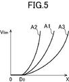
- FIG. 5 is an allowable upper limit of passing speed according to different types of objects.
- FIG. 6 is an explanatory diagram showing the relationship between values and clearances, and FIG. 6 is an explanatory diagram of different types of objects and safety distances according to vehicle absolute speed.
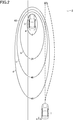
- FIG. 4A shows a case where a guard rail 4 and a lane boundary line 5 are provided along the traveling path 2.
- These objects extend in the longitudinal direction along the travel path 2 and are considered to be formed only by the side surfaces (lateral surfaces), or small objects are continuously arranged in the longitudinal direction. Can do.
- the equal relative speed lines a to d are also set so as to extend along the travel path 2. Therefore, the vehicle 1 is allowed to travel at a high speed in the center of the travel path 2, but the speed is limited to a lower speed as the end of the travel path 2 is approached.
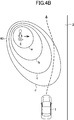
- FIG. 4B shows a case where the pedestrian 6 on the traveling path 2 or the pedestrian 6 on the external walking path near the traveling path 2 is going to cross the traveling path 2.
- the object parked vehicle 3
- the velocity distribution region 40 shown in FIG. 2 is formed such that a substantially elliptical equal relative velocity line extends toward the vehicle 1 along the traveling direction of the vehicle 1.
- the velocity distribution region 40 is set so as to extend toward the vehicle 1 along the traveling direction of the vehicle 1 and also to extend in the lateral direction (right direction in FIG. 4B) along the traveling direction of the object.
- FIG. 4B for example, it can be predicted that the image pedestrian 6 is moving in the right direction from the image data obtained by the in-vehicle camera 21.
- FIG. 4C shows a case where the traffic signal 7 in front of the vehicle 1 on the travel path 2 is “red”.
- equal relative speed lines a to d are set in order from the traffic signal 7 toward the vehicle 1. Therefore, the vehicle 1 gradually decelerates within the speed distribution region 40 and stops at the position of the equal relative speed line a (0 km / h).
- FIG. 5 is a graph similar to FIG. 3, but an example of a guardrail (line A2) and a pedestrian (line A3) is added in addition to the vehicle (line A1).
- the degree of change in the allowable upper limit value V lim with respect to the clearance X is set larger than in the case of the guardrail (line A2) and in the case of the vehicle (line A1).
- coefficient k coefficient of change
- the degree of change (coefficient k) of the allowable upper limit value V lim with respect to the clearance X is set smaller than in the case of a pedestrian (line A3) and in the case of a vehicle (line A1). Thereby, the safety with respect to a pedestrian can be improved more. Further, when the pedestrian is an adult, when the pedestrian is a child, or when there are a plurality of pedestrians, different gains (coefficients k) may be set.
- different safety distances D 0 may be set according to the difference in the type of object.
- the safety distance can be set to decrease in the order of pedestrians, vehicles, and guardrails.
- a larger safety distance may be set for children than adults.
- FIG. 6 shows the relationship between the vehicle speed V ABS (absolute speed) and the safety distance D 0 when the object is a vehicle (line B1), a guardrail (line B2), and a pedestrian (line B3).
- V ABS absolute speed
- D 0 safety distance
- the safety distance is set larger when the vehicle 1 overtakes the preceding vehicle at low speed than when the vehicle 1 overtakes the preceding vehicle.
- the velocity distribution region can be set based on various parameters.
- parameters for example, the relative speed between the vehicle 1 and the object, the type of the object, the traveling direction of the vehicle 1, the moving direction and moving speed of the object, the length of the object, the absolute speed of the vehicle 1 and the like are considered. Can do. That is, the coefficient k and the safety distance D 0 can be selected based on these parameters.
- the object includes a vehicle, a pedestrian, a bicycle, a traveling road section, an obstacle, a traffic signal, a traffic sign, and the like.
- vehicles can be distinguished by automobiles, trucks, and motorcycles.
- Pedestrians can be distinguished by adults, children and groups.
- the traveling road section includes a guide rail, a road shoulder that forms a step at the end of the traveling road, a median strip, and a lane boundary line.
- Obstacles include cliffs, grooves, holes, and falling objects.
- Traffic signs include stop lines and stop signs.
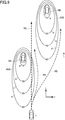
- the velocity distribution regions are shown independently for each object. However, when a plurality of objects are close to each other, the plurality of velocity distribution regions overlap each other. . For this reason, in the overlapping portion, not the substantially elliptical uniform relative velocity line as shown in FIGS. 2 and 4, but the smaller allowable upper limit value is prioritized and the other is excluded, or 2
- the iso-relative velocity line is set so that the two substantially elliptical shapes are smoothly connected.
- FIGS. 7 and 9 are explanatory diagrams of the operation of the vehicle control system
- FIGS. 8 and 10 are explanatory diagrams of the allowable upper limit value of the relative speed
- FIG. 11 is a processing flow of the vehicle control device. 7 and 9, other objects such as guardrails are excluded for easy understanding.
- the ECU 10 data acquisition unit of the vehicle 1 acquires various data from a plurality of sensors (S10). Specifically, the ECU 10 receives image data obtained by imaging the front of the vehicle 1 from the in-vehicle camera 21, receives measurement data from the millimeter wave radar 22, and receives vehicle speed data from the vehicle speed sensor 23.
- ECU10 target object detection part
- the ECU 10 acquires the position and relative speed of the detected object (vehicles 8A and 8B) with respect to the vehicle 1 based on the measurement data.
- the position of the object includes a y-direction position (vertical distance) along the traveling direction of the vehicle 1 and an x-direction position (horizontal distance) along the lateral direction orthogonal to the traveling direction.
- the relative speed the relative speed included in the measurement data may be used as it is, or a speed component along the traveling direction may be calculated from the measurement data.
- the velocity component orthogonal to the traveling direction does not necessarily have to be calculated, but may be estimated from a plurality of measurement data and / or a plurality of image data if necessary.
- the vehicles 8A and 8B are traveling in the same direction as the vehicle 1.
- ECU10 speed distribution area setting unit sets speed distribution areas 40A and 40B for all detected objects (ie, vehicles 8A and 8B), respectively (S12). Then, the ECU 10 (route calculating unit) sets the route in which the vehicle 1 can travel and the positions on the route according to a preset mode based on all the set speed distribution regions 40A and 40B. A vehicle speed or a target speed is calculated (S13).
- the set vehicle speed is set to a value limited by the allowable upper limit values of a plurality of speed distribution regions at each point on the route. That is, the relative speed with respect to the object generated by the set speed is calculated so as to be a smaller allowable upper limit value V lim among the allowable upper limit values of the plurality of speed distribution regions.
- the set speed is adjusted so that the speed change along the route becomes smooth. Then, in order for the vehicle 1 to travel on the calculated route, the ECU 10 (avoidance control execution unit) executes the following avoidance control according to a preset mode (S14).
- the vehicle 1 is configured so that the driver can select a desired driving support mode using an input device (not shown). Further, a predetermined mode may be set in the ECU 10 in advance. Further, since the processing flow of FIG. 11 is repeatedly executed every predetermined time (for example, 0.1 second), the calculated route and the set speed on this route change with time.
- FIG. 8A shows a change in the allowable upper limit value V lim in the horizontal direction (x direction) at the vertical position A (see FIG. 7) where the vehicle 8A is located.
- FIG. 8B shows a change in the allowable upper limit value V lim at the longitudinal position B (see FIG. 7) between the vehicles 8A and 8B.
- x 0 , x A , and x B indicate the center positions in the width direction of the vehicles 1, 8A, and 8B in the x direction, respectively.
- the relative speed of the vehicle 1 is limited by the two velocity distribution regions 40A and 40B. Specifically, as shown in FIGS. 8A and 8B, the relative speed of the vehicle 1 is smaller than the allowable upper limit value defined in the two speed distribution regions 40A and 40B. It is limited by the upper limit (see the solid line in the figure).
- the allowable upper limit value V lim is maximum at the position x 1 in the horizontal direction, and at position B, the allowable upper limit value V lim is maximum at the position x 2. .
- the maximum value (and its horizontal position x) of the allowable upper limit value V lim changes according to the vertical position y.
- Route R1 is a straight route.
- the route R1 is calculated when the straight ahead priority mode (or the shortest distance priority mode) is set.
- the relative speed with respect to the vehicle 8A is about 0 km / h at the longitudinal position A. It is limited by the allowable upper limit value, and the relative speed with respect to the vehicle 8B is limited by the allowable upper limit value of about 60 km / h. Further, at the vertical position B, the relative speed with respect to the vehicles 8A and 8B is limited by an allowable upper limit value of about 50 km / h. Therefore, on the route R1, the vehicle 1 can pass by decelerating and accelerating.
- the vehicle 1 When the automatic speed tracking mode for automatically following the set speed is selected in addition to the straight ahead priority mode, the vehicle 1 is in the y-direction position until the vehicle 1 passes the vehicles 8A and 8B during traveling on the route R1. The vehicle is automatically decelerated so as to follow the permissible upper limit value, and after passing the vehicle 8B, the vehicle is accelerated to the set speed.
- the ECU 10 follows the relative speed of the allowable upper limit value below the set vehicle speed on the route R1, so that the engine control system 31, An engine output change request signal and a brake request signal are output to the brake control system 32, respectively.
- the driver maintains the same accelerator depression amount.
- the speed of the vehicle 1 is automatically controlled by avoidance control as described above. That is, the relative speed of the vehicle 1 is maintained at the allowable upper limit value at each point unless the driver depresses the accelerator depression amount so that the driver decelerates to a relative speed equal to or lower than the allowable upper limit value.
- the vehicle 1 enters the route R1 at a relative speed of 40 km / h for example, if the accelerator depression amount is not decreased, the relative speed is increased until the vehicle 1 enters the equal relative speed line c (corresponding to 40 km / h). It is maintained at 40 km / h (not accelerated / decelerated).
- the route R2 is calculated when a speed priority mode that is a mode setting for suppressing a decrease in vehicle speed is set.
- the route R2 is, for example, a route in which the vehicle 1 traveling at a relative speed of 60 km / h continuously passes through a point where the allowable upper limit value V lim is maximum with the vehicle speed at that time as an upper limit value. That is, the route R2 is a portion that passes between the vehicle 8A and the vehicle 8B, and the point where the two allowable upper limit values V lim of the two velocity distribution regions 40A and 40B are equal to each other in the traveling direction of the vehicle 1. It is formed to extend.
- the allowable upper limit value V lim is 60 km because the route R2 is along the equal relative speed line d of the vehicle 8A until it reaches the equal relative speed line d of the vehicle 8B. / H. Then, within the equal relative speed line d of the vehicle 8B, the route R2 continuously crosses the position in the x direction that is the maximum value of the allowable upper limit value V lim of the two speed distribution regions 40A and 40B. In FIG. 7, the right side of the vehicle 8B is not allowed to pass.
- the vehicle 1 travels on the route R2 by the automatic steering, and the relative speed is the route R2.
- the allowable upper limit value V lim at each of the above points is maintained.
- the ECU 10 outputs a steering direction change request signal to the steering control system 33 so as to travel on the route R2.
- the ECU 10 controls the engine so as to prevent the relative speed from exceeding the allowable upper limit value by following the allowable upper limit value at the vehicle speed or less corresponding to the accelerator depression amount on the route R2.
- An engine output change request signal and a brake request signal are output to the control system 31 and the brake control system 32, respectively.
- the vehicle 1 traveling at a relative speed of 60 km / h changes its course by the driver's operation of the steering wheel and enters the route R2
- the ECU 10 outputs an engine output change request signal and a brake request signal so that the vehicle 1 travels at a set speed that follows the allowable upper limit value on the route R2.
- a route other than the routes R1 and R2 may be calculated according to the driver's preference.
- the path can be calculated using the fluctuation width of the vertical acceleration (vertical G) and the fluctuation width of the horizontal acceleration (horizontal G) on the path as parameters.
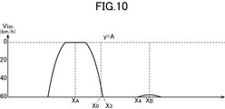
- FIG. 10 shows the allowable upper limit value V lim at the longitudinal position A of the vehicle 8A.
- Route R3 is a straight-ahead route and is calculated when the straight-ahead priority mode is set.
- the route R3 is a straight route similar to the route R1 in FIG.
- the routes R4 and R5 are calculated when the speed priority mode is set.
- a route can be generated so as to pass outside the two equal relative velocity lines d (for example, route R4, R5, etc.), and in such a route, the allowable upper limit value V lim is 60 km / h or more. It becomes. Therefore, the vehicle 1 traveling at a relative speed of 60 km / h can travel on the routes R4 and R5 (recommended travel route) without reducing the relative speed.
- the right side of the vehicle 8B is also allowed to pass.
- the allowable upper limit value V lim is 60 km / h or more between the position x 3 and the position x 4 at the longitudinal position A where the vehicle 8A is located. Only thus, for example, it can be set a path R4 as vehicle 1 was traveling at a relative speed 60 km / h to pass through an arbitrary position between the position x 3 and the position x 4, by various limitations It is possible to configure so as to calculate the route R4.
- a restriction is, for example, a restriction passing through the lateral position x close to the center of the travel path, a restriction passing through the center between the position x 3 and the position x 4 that are the allowable upper limit value at the current relative speed, and the position x 3.
- the vehicle 1 travels so as to avoid the two speed distribution areas 40A and 40B on the left side. Therefore, the distance that the vehicle 1 avoids in the lateral direction is larger on the route R5 than on the route R4.
- the route R4 and R5 may be set in the ECU 10 in advance at the time of manufacture, or the driver manually sets the ECU 10 with an input device (not shown). May be.
- the route R4 and R5 may be set such that the one with the smaller avoidance distance in the horizontal direction (route R4 in the case of FIG. 9) is selected.
- the route R5 may be set to be selected.
- the route (R5) that passes outside the two objects may be given priority over the route (R4) that passes between the two objects, or vice versa. Good.
- the allowable upper limit value on the routes R4 and R5 is at least larger than the relative speed of 60 km / h. Therefore, if the vehicle 1 enters the route R4 or R5 at a relative speed of 60 km / h, the vehicle 1 travels on the route R4 or R5 by automatic steering while maintaining the same vehicle speed.
- the ECU 10 outputs a steering direction change request signal to the steering control system 33 so as to travel on the route R4 or R5.
- the vehicle speed corresponding to the amount of depression of the accelerator is maintained, so the engine output change request signal and the brake request signal are not output.
- the vehicle 1 traveling at a relative speed of 60 km / h changes the course by the driver's operation of the steering wheel and enters the route R4 or R5. Then, the vehicle 1 is not limited by the relative speed by the speed distribution regions 40A and 40B. Therefore, during traveling on the route R4 or R5, the ECU 10 does not output an engine output change request signal or a brake request signal, so that the vehicle speed corresponding to the accelerator depression amount is maintained.
- the speed distribution region 40 is set from the lateral region of the detected object (parked vehicle 3, pedestrian 6, etc.) to the rear region and the front region. In this speed distribution area, an allowable upper limit value of the relative speed of the vehicle with respect to the object is set.
- speed distribution regions 40A, 40B are set for the respective objects, and the relative speed of the vehicle 1 is Control is performed so as not to exceed the allowable upper limit set in the plurality of velocity distribution regions 40A and 40B.
- the relative speed is limited for all surrounding objects.
- the allowable upper limit value for the relative speed between the object and the vehicle is limited, and a safe driving support system such as automatic brake control or steering assist control is integrated. Since it can be controlled, safe driving support can be provided by simple and efficient speed control.
- the velocity distribution region is set so that the allowable upper limit value decreases as the lateral distance and the longitudinal distance from the object are smaller.
- the allowable upper limit with respect to the relative speed of the vehicle 1 may be restrict
- the speed and / or steering direction of the vehicle 1 is changed so that the relative speed of the vehicle 1 in the plurality of speed distribution regions 40A and 40B does not exceed the allowable upper limit value.
- it is configured to change (decelerate) the speed of the vehicle 1 as in the route R1 in FIG. 7, or has a larger allowable upper limit value as in the routes R4 and R5 in FIG.
- the travel route can be changed by changing the steering direction so as to pass through the area, or both the speed and the steering direction can be changed as in the route R2.
- the vehicle since the route of the vehicle 1 is calculated based on the plurality of velocity distribution regions 40A and 40B in the avoidance control, the vehicle can travel along a safe route in relation to the object.
- the route R2 continues at a point where two allowable upper limit values defined for the two vehicles 8A and 8B are equal in a portion where the vehicle 1 passes between the two vehicles 8A and 8B.
- it is formed to extend in the traveling direction of the vehicle 1.
- one or a plurality of recommended travel routes R4 and R5 that can be traveled at the current relative speed of the vehicle 1 are calculated. Therefore, a speed change is caused by traveling on the recommended travel route. It is possible to run the vehicle without any problems.
Abstract
Description
このように構成された本発明によれば、対象物からの距離に応じて車両の相対速度に対する許容上限値が制限されるように構成されており、車両が対象物から遠く離れている場合には、大きな相対速度が許容されるが、車両が対象物と接近している場合には、小さな相対速度となるように車両速度が制限される。
このように構成された本発明によれば、車両の相対速度が、複数の速度分布領域に設定された許容上限値を超えないようにするため、車両の速度自体を変更(減速)するように構成するか、より大きな許容上限値を有するエリアを通過するように操舵方向の変更により走行経路を変更するように構成するか、速度と操舵方向の両方を変更するように構成することができる。
このように構成された本発明によれば、対象物との関係において、安全な経路で車両を走行させることができる。
このように構成された本発明によれば、車両が2つの対象物の間を通過する際には、相対速度の許容上限値が最大となる経路に沿って走行することが可能となる。
このように構成された本発明によれば、複数の対象物が検知されても、これら対象物によって相対速度を低下させることなく走行可能なように、推奨走行経路が算出される。これにより、本発明では、推奨走行経路を走行することにより、速度変化を生じさせることなく車両を走行させることが可能である。
測位システム24は、GPSシステム及び/又はジャイロシステムであり、車両1の位置(現在車両位置情報)を算出する。
ナビゲーションシステム25は、内部に地図情報を格納しており、ECU10へ地図情報を提供することができる。ECU10は、地図情報及び現在車両位置情報に基づいて、車両1の周囲(特に、進行方向前方)に存在する道路、交通信号、建造物等を特定する。また、ECU10は、車載カメラ21による画像データからは特定しにくい崖,溝,穴等を、地図情報に基づいて特定してもよい。地図情報は、ECU10内に格納されていてもよい。
図2では、車両1は走行路2上を走行しており、走行路2の道路脇に駐車された別の車両3とすれ違って、車両3を追い抜こうとしている。
本実施形態では、検知された対象物(駐車車両3、歩行者6等)の横方向領域から後方領域及び前方領域にわたって速度分布領域40が設定される。この速度分布領域には、対象物に対する車両の相対速度の許容上限値が設定される。そして、本実施形態では、複数の対象物(車両8A,8B等)が検知された場合には、それぞれの対象物に対して速度分布領域40A,40Bが設定され、車両1の相対速度が、複数の速度分布領域40A,40Bに設定された許容上限値を超えないように、制御される。したがって、車両が複数の対象物(車両8A,8B等)付近を走行する際に、周囲のすべての対象物に対して相対速度が制限される。このように、本実施形態では、対象物と車両の間の相対速度に対する許容上限値が制限されるように構成されており、自動ブレーキ制御や操舵アシスト制御等の安全運転支援システムを統合して制御できるので、簡易且つ効率的な速度制御により安全運転支援を提供することができる。
2 走行路
4 ガードレール
5 車線境界線
6 歩行者
7 交通信号
21 車載カメラ
22 ミリ波レーダ
23 車速センサ
24 測位システム
25 ナビゲーションシステム
31 エンジン制御システム
32 ブレーキ制御システム
33 ステアリング制御システム
40、40A、40B 速度分布領域
100 車両制御システム
a,b,c,d 等相対速度線
R1、R2、R3、R4,R5 経路
Claims (6)
- 車両に搭載される車両制御装置であって、
前記車両の外部にある対象物を検知し、
前記車両の進行方向に対する前記対象物の横方向領域から後方領域及び前方領域にわたって、前記車両の進行方向における前記対象物に対する前記車両の相対速度の許容上限値の分布を規定する速度分布領域を設定し、
複数の対象物が検知された場合、それぞれの前記対象物に対して前記速度分布領域を設定し、
前記複数の対象物に対する前記車両の相対速度が前記複数の対象物に対する複数の速度分布領域によって規定された前記許容上限値を超えることを抑制する回避制御を実行するように構成されている、車両制御装置。 - 前記速度分布領域は、前記対象物からの横方向距離及び縦方向距離が小さいほど前記許容上限値が低下するように設定される、請求項1に記載の車両制御装置。
- 前記回避制御において、前記複数の速度分布領域内における前記車両の相対速度が前記許容上限値を超えないように前記車両の速度及び/又は操舵方向が変更される、請求項1に記載の車両制御装置。
- 前記回避制御において、前記複数の速度分布領域に基づいて前記車両の経路が算出される、請求項1に記載の車両制御装置。
- 前記経路は、前記車両が前記複数の対象物のうちの2つの対象物の間を通過する部分において、前記2つの対象物に対して規定された2つの許容上限値が等しくなる点を連続して、前記車両の走行方向に延びるように形成される、請求項4に記載の車両制御装置。
- 前記回避制御において、前記車両の現在の相対速度で走行可能な1又は複数の推奨走行経路が算出される、請求項4に記載の車両制御装置。
Priority Applications (5)
| Application Number | Priority Date | Filing Date | Title |
|---|---|---|---|
| EP16915060.4A EP3418151B1 (en) | 2016-08-29 | 2016-08-29 | Vehicle control device |
| CN201680002980.6A CN108012539B (zh) | 2016-08-29 | 2016-08-29 | 车辆控制装置 |
| JP2018536540A JP6656602B2 (ja) | 2016-08-29 | 2016-08-29 | 車両制御装置 |
| PCT/JP2016/075234 WO2018042499A1 (ja) | 2016-08-29 | 2016-08-29 | 車両制御装置 |
| US15/515,089 US10414394B2 (en) | 2016-08-29 | 2016-08-29 | Vehicle control system |
Applications Claiming Priority (1)
| Application Number | Priority Date | Filing Date | Title |
|---|---|---|---|
| PCT/JP2016/075234 WO2018042499A1 (ja) | 2016-08-29 | 2016-08-29 | 車両制御装置 |
Publications (1)
| Publication Number | Publication Date |
|---|---|
| WO2018042499A1 true WO2018042499A1 (ja) | 2018-03-08 |
Family
ID=61300235
Family Applications (1)
| Application Number | Title | Priority Date | Filing Date |
|---|---|---|---|
| PCT/JP2016/075234 WO2018042499A1 (ja) | 2016-08-29 | 2016-08-29 | 車両制御装置 |
Country Status (5)
| Country | Link |
|---|---|
| US (1) | US10414394B2 (ja) |
| EP (1) | EP3418151B1 (ja) |
| JP (1) | JP6656602B2 (ja) |
| CN (1) | CN108012539B (ja) |
| WO (1) | WO2018042499A1 (ja) |
Cited By (1)
| Publication number | Priority date | Publication date | Assignee | Title |
|---|---|---|---|---|
| JPWO2021070451A1 (ja) * | 2019-10-09 | 2021-04-15 |
Families Citing this family (9)
| Publication number | Priority date | Publication date | Assignee | Title |
|---|---|---|---|---|
| WO2018220851A1 (ja) | 2017-06-02 | 2018-12-06 | 本田技研工業株式会社 | 自動運転車の制御のための車両制御装置及び方法 |
| CN110692094B (zh) * | 2017-06-02 | 2022-02-01 | 本田技研工业株式会社 | 用于自动驾驶车的控制的车辆控制装置及方法 |
| JP6926723B2 (ja) * | 2017-06-27 | 2021-08-25 | いすゞ自動車株式会社 | 車速制御装置 |
| JP6937218B2 (ja) * | 2017-10-19 | 2021-09-22 | 株式会社東芝 | 情報処理装置、情報処理方法、およびプログラム |
| US10449959B2 (en) * | 2017-10-30 | 2019-10-22 | Wipro Limited | System and method for navigating an autonomous vehicle |
| JP2020179729A (ja) * | 2019-04-24 | 2020-11-05 | マツダ株式会社 | 車両制御装置 |
| WO2021020311A1 (ja) * | 2019-07-26 | 2021-02-04 | 株式会社Soken | 車両制御装置、車両制御方法、自動運転装置及び自動運転方法 |
| US20220355822A1 (en) * | 2021-05-10 | 2022-11-10 | Toyota Research Institute, Inc. | Method for enumerating homotopies for maneuvers using a hierarchy of tolerance relations |
| CN113501000B (zh) * | 2021-07-28 | 2022-12-20 | 阿波罗智能技术(北京)有限公司 | 车辆限速控制的方法、设备、存储介质及程序产品 |
Citations (5)
| Publication number | Priority date | Publication date | Assignee | Title |
|---|---|---|---|---|
| JP2004220422A (ja) * | 2003-01-16 | 2004-08-05 | Denso Corp | 車両の接触防止システム |
| JP2007512598A (ja) * | 2003-11-28 | 2007-05-17 | ローベルト ボッシュ ゲゼルシャフト ミット ベシュレンクテル ハフツング | 自動車の運転者に警告する方法および装置 |
| JP2013226945A (ja) * | 2012-04-26 | 2013-11-07 | Masahiro Watanabe | 車両走行制御方法 |
| JP2015155295A (ja) * | 2014-01-29 | 2015-08-27 | コンチネンタル オートモーティブ システムズ インコーポレイテッドContinental Automotive Systems, Inc. | 車両の自立運転中に歩行者に適応するためのシステム |
| WO2016024318A1 (ja) * | 2014-08-11 | 2016-02-18 | 日産自動車株式会社 | 車両の走行制御装置及び方法 |
Family Cites Families (13)
| Publication number | Priority date | Publication date | Assignee | Title |
|---|---|---|---|---|
| DE60226817D1 (de) * | 2001-08-23 | 2008-07-10 | Nissan Motor | Fahrassistenzsystem |
| JP3988600B2 (ja) * | 2001-12-14 | 2007-10-10 | 日産自動車株式会社 | 乗員拘束システム |
| US20030189871A1 (en) * | 2002-04-09 | 2003-10-09 | Eastman Kodak Company | Mixing chamber of mixing tow or more liquids under high velocity to produce a solid particle dispersion |
| JP4019825B2 (ja) * | 2002-07-09 | 2007-12-12 | 株式会社ジェイテクト | 電動パワーステアリング装置 |
| JP3948416B2 (ja) * | 2003-02-27 | 2007-07-25 | 株式会社デンソー | 衝突回避制御装置 |
| JP4432464B2 (ja) * | 2003-11-11 | 2010-03-17 | 日産自動車株式会社 | 乗員保護装置 |
| CN1287069C (zh) * | 2003-11-27 | 2006-11-29 | 宁波华液机器制造有限公司 | 一种压差式变气门控制系统 |
| JP2007099237A (ja) | 2005-10-07 | 2007-04-19 | Fuji Heavy Ind Ltd | 車両用運転支援装置 |
| JP5554037B2 (ja) | 2009-09-04 | 2014-07-23 | 本田技研工業株式会社 | 車両用接触回避支援装置 |
| US8655579B2 (en) * | 2010-03-16 | 2014-02-18 | Toyota Jidosha Kabushiki Kaisha | Driving assistance device |
| CN102596635B (zh) * | 2010-09-22 | 2015-11-25 | 丰田自动车株式会社 | 车辆用座椅 |
| JP5189157B2 (ja) * | 2010-11-30 | 2013-04-24 | 株式会社豊田中央研究所 | 可動物の目標状態決定装置及びプログラム |
| WO2016050253A1 (en) * | 2014-10-02 | 2016-04-07 | Volvo Truck Corporation | Method to prevent from a collision between a vehicle and a front obstacle and vehicle associated with this method |
-
2016
- 2016-08-29 JP JP2018536540A patent/JP6656602B2/ja active Active
- 2016-08-29 EP EP16915060.4A patent/EP3418151B1/en active Active
- 2016-08-29 CN CN201680002980.6A patent/CN108012539B/zh active Active
- 2016-08-29 WO PCT/JP2016/075234 patent/WO2018042499A1/ja active Application Filing
- 2016-08-29 US US15/515,089 patent/US10414394B2/en active Active
Patent Citations (5)
| Publication number | Priority date | Publication date | Assignee | Title |
|---|---|---|---|---|
| JP2004220422A (ja) * | 2003-01-16 | 2004-08-05 | Denso Corp | 車両の接触防止システム |
| JP2007512598A (ja) * | 2003-11-28 | 2007-05-17 | ローベルト ボッシュ ゲゼルシャフト ミット ベシュレンクテル ハフツング | 自動車の運転者に警告する方法および装置 |
| JP2013226945A (ja) * | 2012-04-26 | 2013-11-07 | Masahiro Watanabe | 車両走行制御方法 |
| JP2015155295A (ja) * | 2014-01-29 | 2015-08-27 | コンチネンタル オートモーティブ システムズ インコーポレイテッドContinental Automotive Systems, Inc. | 車両の自立運転中に歩行者に適応するためのシステム |
| WO2016024318A1 (ja) * | 2014-08-11 | 2016-02-18 | 日産自動車株式会社 | 車両の走行制御装置及び方法 |
Non-Patent Citations (1)
| Title |
|---|
| See also references of EP3418151A4 * |
Cited By (3)
| Publication number | Priority date | Publication date | Assignee | Title |
|---|---|---|---|---|
| JPWO2021070451A1 (ja) * | 2019-10-09 | 2021-04-15 | ||
| WO2021070451A1 (ja) * | 2019-10-09 | 2021-04-15 | 株式会社Soken | 車両制御装置、車両制御方法、自動運転装置及び自動運転方法 |
| JP7347523B2 (ja) | 2019-10-09 | 2023-09-20 | 株式会社Soken | 車両制御装置及び車両制御方法 |
Also Published As
| Publication number | Publication date |
|---|---|
| CN108012539B (zh) | 2020-11-27 |
| EP3418151B1 (en) | 2023-04-19 |
| JP6656602B2 (ja) | 2020-03-04 |
| US20180345957A1 (en) | 2018-12-06 |
| EP3418151A4 (en) | 2019-05-15 |
| JPWO2018042499A1 (ja) | 2018-12-06 |
| EP3418151A1 (en) | 2018-12-26 |
| US10414394B2 (en) | 2019-09-17 |
| CN108012539A (zh) | 2018-05-08 |
Similar Documents
| Publication | Publication Date | Title |
|---|---|---|
| JP6656601B2 (ja) | 車両制御装置 | |
| JP6380919B2 (ja) | 車両制御装置 | |
| JP6380920B2 (ja) | 車両制御装置 | |
| WO2018225575A1 (ja) | 車両制御装置 | |
| WO2018042499A1 (ja) | 車両制御装置 | |
| WO2018105524A1 (ja) | 車両制御装置 | |
| JP2018203108A (ja) | 車両制御装置 | |
| JP6656603B2 (ja) | 車両制御装置 | |
| JP2018086949A (ja) | 車両制御装置 | |
| WO2018074541A1 (ja) | 車両制御装置 | |
| JP6376522B2 (ja) | 車両制御装置 | |
| JP6331233B2 (ja) | 車両制御装置 | |
| JP6447962B2 (ja) | 車両制御装置 | |
| JP6376520B2 (ja) | 車両制御装置 | |
| JP6376521B2 (ja) | 車両制御装置 | |
| JP6347420B2 (ja) | 車両制御装置 | |
| JP6331234B2 (ja) | 車両制御装置 | |
| JP2018086945A (ja) | 車両制御装置 | |
| JP6447963B2 (ja) | 車両制御装置 |
Legal Events
| Date | Code | Title | Description |
|---|---|---|---|
| WWE | Wipo information: entry into national phase |
Ref document number: 2018536540 Country of ref document: JP |
|
| WWE | Wipo information: entry into national phase |
Ref document number: 2016915060 Country of ref document: EP |
|
| ENP | Entry into the national phase |
Ref document number: 2016915060 Country of ref document: EP Effective date: 20180917 |
|
| 121 | Ep: the epo has been informed by wipo that ep was designated in this application |
Ref document number: 16915060 Country of ref document: EP Kind code of ref document: A1 |
|
| NENP | Non-entry into the national phase |
Ref country code: DE |