WO2018038151A1 - 積層構造、及び、積層構造を有する機械部品 - Google Patents
積層構造、及び、積層構造を有する機械部品 Download PDFInfo
- Publication number
- WO2018038151A1 WO2018038151A1 PCT/JP2017/030096 JP2017030096W WO2018038151A1 WO 2018038151 A1 WO2018038151 A1 WO 2018038151A1 JP 2017030096 W JP2017030096 W JP 2017030096W WO 2018038151 A1 WO2018038151 A1 WO 2018038151A1
- Authority
- WO
- WIPO (PCT)
- Prior art keywords
- layer
- base material
- dlc
- nitride layer
- laminated structure
- Prior art date
- Legal status (The legal status is an assumption and is not a legal conclusion. Google has not performed a legal analysis and makes no representation as to the accuracy of the status listed.)
- Ceased
Links
Images




Classifications
-
- C—CHEMISTRY; METALLURGY
- C23—COATING METALLIC MATERIAL; COATING MATERIAL WITH METALLIC MATERIAL; CHEMICAL SURFACE TREATMENT; DIFFUSION TREATMENT OF METALLIC MATERIAL; COATING BY VACUUM EVAPORATION, BY SPUTTERING, BY ION IMPLANTATION OR BY CHEMICAL VAPOUR DEPOSITION, IN GENERAL; INHIBITING CORROSION OF METALLIC MATERIAL OR INCRUSTATION IN GENERAL
- C23C—COATING METALLIC MATERIAL; COATING MATERIAL WITH METALLIC MATERIAL; SURFACE TREATMENT OF METALLIC MATERIAL BY DIFFUSION INTO THE SURFACE, BY CHEMICAL CONVERSION OR SUBSTITUTION; COATING BY VACUUM EVAPORATION, BY SPUTTERING, BY ION IMPLANTATION OR BY CHEMICAL VAPOUR DEPOSITION, IN GENERAL
- C23C8/00—Solid state diffusion of only non-metal elements into metallic material surfaces; Chemical surface treatment of metallic material by reaction of the surface with a reactive gas, leaving reaction products of surface material in the coating, e.g. conversion coatings, passivation of metals
- C23C8/06—Solid state diffusion of only non-metal elements into metallic material surfaces; Chemical surface treatment of metallic material by reaction of the surface with a reactive gas, leaving reaction products of surface material in the coating, e.g. conversion coatings, passivation of metals using gases
- C23C8/36—Solid state diffusion of only non-metal elements into metallic material surfaces; Chemical surface treatment of metallic material by reaction of the surface with a reactive gas, leaving reaction products of surface material in the coating, e.g. conversion coatings, passivation of metals using gases using ionised gases, e.g. ionitriding
- C23C8/38—Treatment of ferrous surfaces
-
- B—PERFORMING OPERATIONS; TRANSPORTING
- B32—LAYERED PRODUCTS
- B32B—LAYERED PRODUCTS, i.e. PRODUCTS BUILT-UP OF STRATA OF FLAT OR NON-FLAT, e.g. CELLULAR OR HONEYCOMB, FORM
- B32B15/00—Layered products comprising a layer of metal
- B32B15/04—Layered products comprising a layer of metal comprising metal as the main or only constituent of a layer, which is next to another layer of the same or of a different material
-
- C—CHEMISTRY; METALLURGY
- C23—COATING METALLIC MATERIAL; COATING MATERIAL WITH METALLIC MATERIAL; CHEMICAL SURFACE TREATMENT; DIFFUSION TREATMENT OF METALLIC MATERIAL; COATING BY VACUUM EVAPORATION, BY SPUTTERING, BY ION IMPLANTATION OR BY CHEMICAL VAPOUR DEPOSITION, IN GENERAL; INHIBITING CORROSION OF METALLIC MATERIAL OR INCRUSTATION IN GENERAL
- C23C—COATING METALLIC MATERIAL; COATING MATERIAL WITH METALLIC MATERIAL; SURFACE TREATMENT OF METALLIC MATERIAL BY DIFFUSION INTO THE SURFACE, BY CHEMICAL CONVERSION OR SUBSTITUTION; COATING BY VACUUM EVAPORATION, BY SPUTTERING, BY ION IMPLANTATION OR BY CHEMICAL VAPOUR DEPOSITION, IN GENERAL
- C23C16/00—Chemical coating by decomposition of gaseous compounds, without leaving reaction products of surface material in the coating, i.e. chemical vapour deposition [CVD] processes
- C23C16/02—Pretreatment of the material to be coated
-
- C—CHEMISTRY; METALLURGY
- C23—COATING METALLIC MATERIAL; COATING MATERIAL WITH METALLIC MATERIAL; CHEMICAL SURFACE TREATMENT; DIFFUSION TREATMENT OF METALLIC MATERIAL; COATING BY VACUUM EVAPORATION, BY SPUTTERING, BY ION IMPLANTATION OR BY CHEMICAL VAPOUR DEPOSITION, IN GENERAL; INHIBITING CORROSION OF METALLIC MATERIAL OR INCRUSTATION IN GENERAL
- C23C—COATING METALLIC MATERIAL; COATING MATERIAL WITH METALLIC MATERIAL; SURFACE TREATMENT OF METALLIC MATERIAL BY DIFFUSION INTO THE SURFACE, BY CHEMICAL CONVERSION OR SUBSTITUTION; COATING BY VACUUM EVAPORATION, BY SPUTTERING, BY ION IMPLANTATION OR BY CHEMICAL VAPOUR DEPOSITION, IN GENERAL
- C23C16/00—Chemical coating by decomposition of gaseous compounds, without leaving reaction products of surface material in the coating, i.e. chemical vapour deposition [CVD] processes
- C23C16/22—Chemical coating by decomposition of gaseous compounds, without leaving reaction products of surface material in the coating, i.e. chemical vapour deposition [CVD] processes characterised by the deposition of inorganic material, other than metallic material
- C23C16/26—Deposition of carbon only
- C23C16/27—Diamond only
-
- C—CHEMISTRY; METALLURGY
- C23—COATING METALLIC MATERIAL; COATING MATERIAL WITH METALLIC MATERIAL; CHEMICAL SURFACE TREATMENT; DIFFUSION TREATMENT OF METALLIC MATERIAL; COATING BY VACUUM EVAPORATION, BY SPUTTERING, BY ION IMPLANTATION OR BY CHEMICAL VAPOUR DEPOSITION, IN GENERAL; INHIBITING CORROSION OF METALLIC MATERIAL OR INCRUSTATION IN GENERAL
- C23C—COATING METALLIC MATERIAL; COATING MATERIAL WITH METALLIC MATERIAL; SURFACE TREATMENT OF METALLIC MATERIAL BY DIFFUSION INTO THE SURFACE, BY CHEMICAL CONVERSION OR SUBSTITUTION; COATING BY VACUUM EVAPORATION, BY SPUTTERING, BY ION IMPLANTATION OR BY CHEMICAL VAPOUR DEPOSITION, IN GENERAL
- C23C28/00—Coating for obtaining at least two superposed coatings either by methods not provided for in a single one of groups C23C2/00 - C23C26/00 or by combinations of methods provided for in subclasses C23C and C25C or C25D
- C23C28/04—Coating for obtaining at least two superposed coatings either by methods not provided for in a single one of groups C23C2/00 - C23C26/00 or by combinations of methods provided for in subclasses C23C and C25C or C25D only coatings of inorganic non-metallic material
- C23C28/042—Coating for obtaining at least two superposed coatings either by methods not provided for in a single one of groups C23C2/00 - C23C26/00 or by combinations of methods provided for in subclasses C23C and C25C or C25D only coatings of inorganic non-metallic material including a refractory ceramic layer, e.g. refractory metal oxides, ZrO2, rare earth oxides
-
- C—CHEMISTRY; METALLURGY
- C23—COATING METALLIC MATERIAL; COATING MATERIAL WITH METALLIC MATERIAL; CHEMICAL SURFACE TREATMENT; DIFFUSION TREATMENT OF METALLIC MATERIAL; COATING BY VACUUM EVAPORATION, BY SPUTTERING, BY ION IMPLANTATION OR BY CHEMICAL VAPOUR DEPOSITION, IN GENERAL; INHIBITING CORROSION OF METALLIC MATERIAL OR INCRUSTATION IN GENERAL
- C23C—COATING METALLIC MATERIAL; COATING MATERIAL WITH METALLIC MATERIAL; SURFACE TREATMENT OF METALLIC MATERIAL BY DIFFUSION INTO THE SURFACE, BY CHEMICAL CONVERSION OR SUBSTITUTION; COATING BY VACUUM EVAPORATION, BY SPUTTERING, BY ION IMPLANTATION OR BY CHEMICAL VAPOUR DEPOSITION, IN GENERAL
- C23C28/00—Coating for obtaining at least two superposed coatings either by methods not provided for in a single one of groups C23C2/00 - C23C26/00 or by combinations of methods provided for in subclasses C23C and C25C or C25D
- C23C28/04—Coating for obtaining at least two superposed coatings either by methods not provided for in a single one of groups C23C2/00 - C23C26/00 or by combinations of methods provided for in subclasses C23C and C25C or C25D only coatings of inorganic non-metallic material
- C23C28/046—Coating for obtaining at least two superposed coatings either by methods not provided for in a single one of groups C23C2/00 - C23C26/00 or by combinations of methods provided for in subclasses C23C and C25C or C25D only coatings of inorganic non-metallic material with at least one amorphous inorganic material layer, e.g. DLC, a-C:H, a-C:Me, the layer being doped or not
-
- C—CHEMISTRY; METALLURGY
- C23—COATING METALLIC MATERIAL; COATING MATERIAL WITH METALLIC MATERIAL; CHEMICAL SURFACE TREATMENT; DIFFUSION TREATMENT OF METALLIC MATERIAL; COATING BY VACUUM EVAPORATION, BY SPUTTERING, BY ION IMPLANTATION OR BY CHEMICAL VAPOUR DEPOSITION, IN GENERAL; INHIBITING CORROSION OF METALLIC MATERIAL OR INCRUSTATION IN GENERAL
- C23C—COATING METALLIC MATERIAL; COATING MATERIAL WITH METALLIC MATERIAL; SURFACE TREATMENT OF METALLIC MATERIAL BY DIFFUSION INTO THE SURFACE, BY CHEMICAL CONVERSION OR SUBSTITUTION; COATING BY VACUUM EVAPORATION, BY SPUTTERING, BY ION IMPLANTATION OR BY CHEMICAL VAPOUR DEPOSITION, IN GENERAL
- C23C8/00—Solid state diffusion of only non-metal elements into metallic material surfaces; Chemical surface treatment of metallic material by reaction of the surface with a reactive gas, leaving reaction products of surface material in the coating, e.g. conversion coatings, passivation of metals
- C23C8/80—After-treatment
-
- F—MECHANICAL ENGINEERING; LIGHTING; HEATING; WEAPONS; BLASTING
- F01—MACHINES OR ENGINES IN GENERAL; ENGINE PLANTS IN GENERAL; STEAM ENGINES
- F01D—NON-POSITIVE DISPLACEMENT MACHINES OR ENGINES, e.g. STEAM TURBINES
- F01D25/00—Component parts, details, or accessories, not provided for in, or of interest apart from, other groups
-
- F—MECHANICAL ENGINEERING; LIGHTING; HEATING; WEAPONS; BLASTING
- F01—MACHINES OR ENGINES IN GENERAL; ENGINE PLANTS IN GENERAL; STEAM ENGINES
- F01D—NON-POSITIVE DISPLACEMENT MACHINES OR ENGINES, e.g. STEAM TURBINES
- F01D5/00—Blades; Blade-carrying members; Heating, heat-insulating, cooling or antivibration means on the blades or the members
- F01D5/12—Blades
- F01D5/28—Selecting particular materials; Particular measures relating thereto; Measures against erosion or corrosion
-
- F—MECHANICAL ENGINEERING; LIGHTING; HEATING; WEAPONS; BLASTING
- F01—MACHINES OR ENGINES IN GENERAL; ENGINE PLANTS IN GENERAL; STEAM ENGINES
- F01D—NON-POSITIVE DISPLACEMENT MACHINES OR ENGINES, e.g. STEAM TURBINES
- F01D5/00—Blades; Blade-carrying members; Heating, heat-insulating, cooling or antivibration means on the blades or the members
- F01D5/12—Blades
- F01D5/28—Selecting particular materials; Particular measures relating thereto; Measures against erosion or corrosion
- F01D5/288—Protective coatings for blades
-
- F—MECHANICAL ENGINEERING; LIGHTING; HEATING; WEAPONS; BLASTING
- F04—POSITIVE - DISPLACEMENT MACHINES FOR LIQUIDS; PUMPS FOR LIQUIDS OR ELASTIC FLUIDS
- F04C—ROTARY-PISTON, OR OSCILLATING-PISTON, POSITIVE-DISPLACEMENT MACHINES FOR LIQUIDS; ROTARY-PISTON, OR OSCILLATING-PISTON, POSITIVE-DISPLACEMENT PUMPS
- F04C15/00—Component parts, details or accessories of machines, pumps or pumping installations, not provided for in groups F04C2/00 - F04C14/00
-
- F—MECHANICAL ENGINEERING; LIGHTING; HEATING; WEAPONS; BLASTING
- F05—INDEXING SCHEMES RELATING TO ENGINES OR PUMPS IN VARIOUS SUBCLASSES OF CLASSES F01-F04
- F05D—INDEXING SCHEME FOR ASPECTS RELATING TO NON-POSITIVE-DISPLACEMENT MACHINES OR ENGINES, GAS-TURBINES OR JET-PROPULSION PLANTS
- F05D2230/00—Manufacture
- F05D2230/30—Manufacture with deposition of material
- F05D2230/31—Layer deposition
- F05D2230/313—Layer deposition by physical vapour deposition
-
- F—MECHANICAL ENGINEERING; LIGHTING; HEATING; WEAPONS; BLASTING
- F05—INDEXING SCHEMES RELATING TO ENGINES OR PUMPS IN VARIOUS SUBCLASSES OF CLASSES F01-F04
- F05D—INDEXING SCHEME FOR ASPECTS RELATING TO NON-POSITIVE-DISPLACEMENT MACHINES OR ENGINES, GAS-TURBINES OR JET-PROPULSION PLANTS
- F05D2230/00—Manufacture
- F05D2230/30—Manufacture with deposition of material
- F05D2230/31—Layer deposition
- F05D2230/314—Layer deposition by chemical vapour deposition
-
- F—MECHANICAL ENGINEERING; LIGHTING; HEATING; WEAPONS; BLASTING
- F05—INDEXING SCHEMES RELATING TO ENGINES OR PUMPS IN VARIOUS SUBCLASSES OF CLASSES F01-F04
- F05D—INDEXING SCHEME FOR ASPECTS RELATING TO NON-POSITIVE-DISPLACEMENT MACHINES OR ENGINES, GAS-TURBINES OR JET-PROPULSION PLANTS
- F05D2300/00—Materials; Properties thereof
- F05D2300/20—Oxide or non-oxide ceramics
- F05D2300/22—Non-oxide ceramics
- F05D2300/224—Carbon, e.g. graphite
-
- F—MECHANICAL ENGINEERING; LIGHTING; HEATING; WEAPONS; BLASTING
- F05—INDEXING SCHEMES RELATING TO ENGINES OR PUMPS IN VARIOUS SUBCLASSES OF CLASSES F01-F04
- F05D—INDEXING SCHEME FOR ASPECTS RELATING TO NON-POSITIVE-DISPLACEMENT MACHINES OR ENGINES, GAS-TURBINES OR JET-PROPULSION PLANTS
- F05D2300/00—Materials; Properties thereof
- F05D2300/20—Oxide or non-oxide ceramics
- F05D2300/22—Non-oxide ceramics
- F05D2300/226—Carbides
- F05D2300/2261—Carbides of silicon
-
- F—MECHANICAL ENGINEERING; LIGHTING; HEATING; WEAPONS; BLASTING
- F05—INDEXING SCHEMES RELATING TO ENGINES OR PUMPS IN VARIOUS SUBCLASSES OF CLASSES F01-F04
- F05D—INDEXING SCHEME FOR ASPECTS RELATING TO NON-POSITIVE-DISPLACEMENT MACHINES OR ENGINES, GAS-TURBINES OR JET-PROPULSION PLANTS
- F05D2300/00—Materials; Properties thereof
- F05D2300/20—Oxide or non-oxide ceramics
- F05D2300/22—Non-oxide ceramics
- F05D2300/228—Nitrides
- F05D2300/2283—Nitrides of silicon
-
- Y—GENERAL TAGGING OF NEW TECHNOLOGICAL DEVELOPMENTS; GENERAL TAGGING OF CROSS-SECTIONAL TECHNOLOGIES SPANNING OVER SEVERAL SECTIONS OF THE IPC; TECHNICAL SUBJECTS COVERED BY FORMER USPC CROSS-REFERENCE ART COLLECTIONS [XRACs] AND DIGESTS
- Y02—TECHNOLOGIES OR APPLICATIONS FOR MITIGATION OR ADAPTATION AGAINST CLIMATE CHANGE
- Y02T—CLIMATE CHANGE MITIGATION TECHNOLOGIES RELATED TO TRANSPORTATION
- Y02T50/00—Aeronautics or air transport
- Y02T50/60—Efficient propulsion technologies, e.g. for aircraft
Definitions
- the present invention relates to a laminated structure and a mechanical component having a laminated structure.
- rotating parts including blades used in rotating machines such as steam turbines and compressor pumps have been subjected to surface treatment in consideration of heat resistance and corrosion resistance.
- steam which is a working fluid
- components of a rotating machine such as steam turbine blades and rotors that are the rotor blades are in direct contact with the steam.
- an impeller that is powered from the outside rotates to compress the fluids.
- components of a rotating machine such as an impeller and a rotor are in direct contact with the gas.
- a so-called fouling phenomenon may occur in which a ceramic component contained in the gas, for example, SiO 2 adheres.
- a ceramic component contained in the gas for example, SiO 2 adheres.
- Patent Document 1 discloses a DLC layer in which a surface smoothing film is a carbon layer whose maximum surface roughness Ry does not exceed 1.0 ⁇ m in a rotating machine having a surface smoothing film at a portion in direct contact with gas. It is proposed to form with. Patent Document 1 also proposes forming a hard nitride layer made of, for example, chromium nitride (CrN) on the surface of a base material, and forming a surface smoothing film on the surface.
- a hard nitride layer made of, for example, chromium nitride (CrN)
- Patent Document 2 and Patent Document 3 propose to sequentially stack a hard film such as TiN and TiAlN and a fouling prevention film made of a DLC film containing fluorine on the surface of the base material.
- Patent Document 4 includes a multi-layer in which an adhesive base layer that can be bonded to a metal base material and a top surface layer having a surface roughness of about Ra 0.0254 ⁇ m or less, and at least one of the adhesive base layers is diamond-like carbon. It is proposed to form a coating.
- Patent Document 1 has insufficient adhesion between the DLC film and the hard nitride layer
- Patent Document 2 and Patent Document 3 also have insufficient adhesion between the fluorine-containing DLC film and the hard film.
- Patent Document 4 when a drain collides with the uppermost DLC layer, the impact reaches the base material, a minute dent is generated in the base material, and the DLC layer cannot follow this dent. The layer may crack. As a result, the DLC layer is peeled off.
- an object of the present invention is to provide a laminated structure capable of improving the adhesion of a DLC layer and ensuring erosion resistance and fouling resistance. Moreover, an object of this invention is to provide the components for rotary machines provided with such a laminated structure.
- the laminated structure of the present invention includes a base material made of an iron-based metal material, a nitride layer formed on the surface of the base material by nitriding the base material, and an intermediate layer formed on the surface of the nitride layer. And a DLC layer formed on the surface of the intermediate layer.
- the nitride layer has a hardness intermediate between the base material and the DLC layer, and the hardness increases continuously from the base material toward the DLC layer.
- the thickness of the nitride layer is preferably 10 to 100 ⁇ m. In the laminated structure of the present invention, the thickness of the nitride layer is more preferably 25 to 80 ⁇ m. In the laminated structure of the present invention, a diffusion layer in which nitrogen is diffused in the base material is preferably provided at the interface between the nitride layer and the base material.
- the intermediate layer preferably has a thickness of 0.5 to 2 ⁇ m.
- the intermediate layer is preferably composed of one or two of SiC and Si 3 N 4 .
- the intermediate layer may be harder than the nitride layer, or may be harder than the DLC layer.
- the thickness of the DLC layer is preferably 1 to 10 ⁇ m.
- the laminated structure of the present invention described above is applied to rotating machine parts, and is particularly preferably applied to steam turbine or compressor parts.
- the laminated structure of the present invention is a laminated structure in which a nitride layer is provided on the surface of the matrix by nitriding the matrix, an intermediate layer is provided on the nitride layer, and a DLC layer is formed on the intermediate layer. It is what you have.
- the internal stress applied to the DLC layer is relieved by interposing the nitride layer and the intermediate layer. Therefore, even if a drain collides with the DLC layer and an impact is applied, the DLC layer peels off. It is difficult to cause cracks and a laminated structure with excellent adhesion can be obtained.
- the DLC layer has erosion resistance and its own surface energy is small, it has sufficient fouling resistance. That is, by adopting the laminated structure of the present invention, it is possible to provide a rotating machine component that has excellent adhesion and has both erosion resistance and fouling resistance.
- the laminated structure 1 includes a base material 3, a nitride layer 5 formed on the surface of the base material 3, an intermediate layer 6 formed on the surface of the nitride layer 5, It has a DLC layer 7 formed on the surface of the intermediate layer 6 and exhibits erosion resistance and fouling resistance by being applied to a rotating machine described later.
- the laminated structure 1 improves the adhesion of the DLC layer 7 by laminating the DLC layer 7 via the nitride layer 5 formed by nitriding the surface of the base material 3 and the intermediate layer 6.
- the base material 3, the nitride layer 5, and the DLC layer 7 will be described in this order, and then the results of evaluating the laminated structure 1 will be described.
- the base material 3 of the laminated structure 1 is made of an iron-based metal material that constitutes various parts of the rotary machine.
- Examples of the base material 3 include martensitic stainless steel typified by SUS403 and SUS410J1, austenitic stainless steel typified by SUS301 and SUS301J1, ferritic stainless steel typified by SUS430 and SUS410L, and SUS329J1.
- the present invention can be applied without limitation to ferrous metal materials generally used in rotating machines.
- the base material 3 varies depending on the metal material used, the above-described stainless steel generally has a Vickers hardness (Hv) of 200 to 500.
- the base material 3 in the present embodiment refers to a portion excluding the nitride layer 5 formed on the surface thereof.
- hardness Hv and its measurement procedure are based on JISZ2244 including the Example mentioned later.
- the nitride layer 5 is formed in order to improve the adhesion of the DLC layer 7 described later and buffer the impact caused by the collision of the drain.
- the nitride layer 5 is made of a compound mainly composed of nitride of iron (Fe), which is the main component of the base material 3, but a diffusion layer in which nitrogen diffuses is formed at the interface with the base material 3.
- the nitride layer 5 is interposed between the base material 3 and the DLC layer 7, and its hardness shows an intermediate value between the base material 3 and the DLC layer 7, but is obtained by nitriding the base material 3. .
- the diffusion layer of the nitride layer 5 has a hardness equivalent to that of the base material 3 in the vicinity of the interface with the base material 3, and is more closely attached to the base material 3 than the nitride formed on the base material 3. High nature.
- the nitride layer 5 is provided to prevent the base material 3 from being locally deformed, and has a hardness intermediate between the base material 3 and the DLC layer 7.
- the nitride layer 5 has an inclined structure in which the hardness thereof continuously increases from the base material 3 toward the DLC layer 7.
- SUS410J1 constitutes the base material 3
- the nitride layer 5 has an inclined structure in which the hardness continuously increases from the base material 3 toward the DLC layer 7, and the hardness varies in the thickness direction.
- the nitride layer 5 is formed in the thickness direction from the original surface of the base material 3 by nitriding the surface of the base material 3 by a method described later.
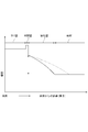
- the nitride layer 5 can be adjusted to be thicker as indicated by the alternate long and short dash line in FIG. 2 or to be thinner as indicated by the solid line in FIG. 2 depending on the nitriding time and other conditions. it can. If the nitride layer 5 is too thin, the effect of providing the nitride layer 5 may not be sufficiently obtained. Further, even if the nitride layer 5 is made thicker than necessary, the effect is saturated, but the processing time becomes long and the economy is impaired.
- the thickness of the nitride layer 5 is preferably 10 to 100 ⁇ m, more preferably 20 to 90 ⁇ m, and further preferably 25 to 80 ⁇ m. Note that the thickness of the nitride layer 5 is defined by the thickness including the diffusion layer described above (JIS B 6905), and the measurement of the thickness in Examples described later is the same. Since the nitride layer 5 has a diffusion layer, as shown in FIG. 2, the nitride layer 5 has an inclined structure in which the hardness decreases from the surface 71 of the DLC layer 7 in the thickness direction.
- nitride layer 5 that is harder than the base material 3 is formed on the surface of the base material 3 and interposed between the base material 3 and the DLC layer 7, the nitridation is performed even if the drain collides with the DLC layer 7. Since the layer 5 resists the impact, the nitride layer 5 relaxes the impact applied to the DLC layer 7, so that deformation of the base material 3 can be suppressed. As described above, the nitride layer 5 suppresses the occurrence of cracking or peeling in the DLC layer 7. That is, the nitride layer 5 improves the adhesion of the DLC layer 7 by stress relaxation.
- the nitride layer 5 has an inclined structure in which the hardness is continuously increased in the direction from the base material 3 to the DLC layer 7, it is possible to prevent a sudden change in shape with respect to the shearing force. Thereby, the nitride layer 5 can suppress stress concentration and can prevent the DLC layer 7 from cracking.
- the means for forming the nitride layer 5 is arbitrary, and a known nitriding treatment can be applied.
- a known nitriding treatment can be applied.
- ion nitriding treatment and radical nitriding treatment can be applied.
- ion nitriding when a base material 3 is used as a cathode and a furnace body is used as an anode in a decompressed vacuum furnace and nitrogen and hydrogen are introduced as reaction gases in the furnace and a DC voltage of several hundred volts is applied, Causes glow discharge.
- + (plus) charged nitrogen ions and hydrogen ions collide with the base material 3 which is a cathode, but due to this collision, the base material 3 is heated and nitride is generated and diffuses inside the base material 3.
- the nitride layer 5 is formed.
- the thickness of the nitride layer 5 formed by the plasma nitriding process can be adjusted by changing the processing temperature, the bias voltage, the processing time, and the partial pressure ratio of nitrogen gas to hydrogen gas.
- Radical nitriding is a kind of plasma nitriding method.
- a mixed gas of ammonia gas and hydrogen gas is introduced into the furnace to cause glow discharge between the furnace body and the base material 3, and nitrogen ions in the plasma are removed.
- the nitride layer 5 is formed on the surface by reacting with the metal of the base material 3.
- the thickness of the nitride layer 5 formed by radical nitridation treatment can be adjusted by changing the treatment temperature, bias voltage, treatment time, and partial pressure ratio of hydrogen gas and ammonia gas.
- the intermediate layer 6 is formed on the surface of the nitride layer 5 described above. This is to improve the adhesion of the DLC layer 7 together with the nitride layer 5.
- the intermediate layer 6, SiC (silicon carbide), any one of Si 3 N 4 (silicon nitride) and SiCN (silicon carbon nitride), or, two or more layers are laminated. Of these, one in which one or two of SiC and Si 3 N 4 are laminated is preferable.
- the hardness of the intermediate layer 6 varies depending on whether the intermediate layer 6 is made of SiC, Si 3 N 4, or SiCN.
- the hardness of the intermediate layer 6 made of SiC is converted from the nanoindentation hardness measured by nanoindentation from the cross-sectional direction orthogonal to the thickness direction of the intermediate layer 6 to Vickers hardness. It is a thing.
- the hardness of the intermediate layer 6 is also measured from the cross-sectional direction in the examples described later.
- the DLC layer 7 is laminated on the surface of the intermediate layer 6. It is also possible to measure from the surface direction orthogonal to the surface of the intermediate layer 6 regardless of whether or not it is present.
- the adhesion of the DLC layer 7 is improved due to the presence of carbon, which is a component of the DLC layer 7, and nitrogen, which is a component of the nitride layer 5. Through this, the erosion resistance of the DLC layer 7 is improved.
- the intermediate layer 6 can be made to have a desired thickness by appropriately setting conditions in the method for forming the intermediate layer 6 described later, but the thickness is preferably 0.5 to 2 ⁇ m.
- the means for forming the intermediate layer 6 is performed by plasma treatment following the ion nitriding treatment or radical nitriding treatment.
- the nitride layer 5 is formed by ion nitriding and the intermediate layer 6 made of SiC is formed, first, the nitrogen and hydrogen introduced during the nitriding treatment in the vacuum furnace are gradually reduced, and the vacuum furnace A Si-based gas (eg, hexamethyldisiloxane gas) and a DLC source gas (eg, acetylene gas) are introduced therein. Then, the intermediate layer 6 made of SiC is formed by performing plasma treatment on the base material 3 on which the nitride layer 5 is formed in a state where the Si-based gas and the DLC source gas are present in the vacuum furnace. Be filmed.
- Si-based gas eg, hexamethyldisiloxane gas
- a DLC source gas eg, acetylene gas
- the intermediate layer 6 made of Si 3 N 4 is introduced with Si-based gas (for example, hexamethyldisiloxane gas) into the vacuum furnace and introduced into the vacuum furnace with Si-based gas and nitriding treatment.
- Si-based gas for example, hexamethyldisiloxane gas
- a film is formed by performing plasma treatment on the base material 3 on which the nitride layer 5 is formed in the presence of the nitrogen thus formed.
- the intermediate layer 6 made of SiCN introduces a Si-based gas (for example, hexamethyldisiloxane gas) and a DLC source gas (for example, acetylene gas) into the vacuum furnace tank.
- a film is formed by performing plasma treatment on the base material 3 on which the nitride layer 5 is formed in the presence of Si-based gas, DLC source gas, and nitrogen introduced during nitriding.
- the nitride layer 5 is formed by radical nitriding and the intermediate layer 6 made of SiC is formed, first, ammonia and hydrogen gas during nitriding treatment in the vacuum furnace tank are gradually reduced, and in the vacuum furnace tank Then, Si-based gas (for example, hexamethyldisiloxane gas) and DLC source gas (for example, acetylene gas) are introduced. Then, the intermediate layer 6 made of SiC is formed by performing plasma treatment on the base material 3 on which the nitride layer 5 is formed in a state where the Si-based gas and the DLC source gas are present in the vacuum furnace. Be filmed.
- Si-based gas for example, hexamethyldisiloxane gas
- DLC source gas for example, acetylene gas
- the intermediate layer 6 made of Si 3 N 4 is introduced into the vacuum furnace tank by introducing Si-based gas (for example, hexamethyldisiloxane gas), and introduced into the vacuum furnace tank at the time of nitriding with the Si-based gas.
- Si-based gas for example, hexamethyldisiloxane gas
- a film is formed by performing plasma treatment on the base material 3 on which the nitride layer 5 is formed in the presence of the ammonia gas.
- the intermediate layer 6 made of SiCN introduces a Si-based gas (for example, hexamethyldisiloxane gas) and a DLC source gas (for example, acetylene gas) into the vacuum furnace tank.
- a film is formed by performing plasma treatment on the base material 3 on which the nitride layer 5 is formed in the presence of Si-based gas, DLC source gas, and ammonia gas introduced during nitriding.
- the DLC layer 7 is formed on the surface of the nitride layer 5 and is positioned on the outermost surface (outermost layer) of the multilayer structure 1, thereby imparting erosion resistance and fouling resistance to the multilayer structure 1.
- DLC Diamond Like Carbon
- the range of hardness in the same DLC is mainly due to the difference in the constituent elements of DLC.
- DLC can be broadly divided into constituent elements composed of carbon and hydrogen and constituent elements composed of only carbon, and this difference is due to the difference in the manufacturing method when forming DLC. Furthermore, even in DLC containing hydrogen, hardness and other properties are different due to the difference in hydrogen content. In general, the DLC layer can be controlled to increase the hardness by reducing the hydrogen content.
- the DLC layer 7 in the present embodiment tends to be inferior in erosion resistance both when the hardness is low and when it is high.
- the hardness of the DLC layer 7 can be specified by nanoindentation applied to thin film hardness measurement. This is because nanoindentation hardness is effective in evaluating erosion resistance, as shown in the examples described later.
- the nanoindentation hardness of the DLC layer 7 is preferably 13 to 30 GPa, and preferably 14 to 27 GPa. Is more preferable, and 15 to 25 GPa is even more preferable.
- the hardness of the DLC layer 7 is measured from the surface direction also in the Example mentioned later, it is also possible to measure from the cross-sectional direction orthogonal to the thickness direction of the DLC layer 7.
- the thickness of the DLC layer 7 can be set in consideration of the replacement period of the rotating machine part having the laminated structure 1 described later.
- the thickness is preferably 1 to 10 ⁇ m, and preferably 1 to 8 ⁇ m. More preferably, the thickness is 2 to 5 ⁇ m.
- DLC film deposition methods include PVD (Physical Vapor Deposition), which uses sputtering or cathodic arc discharge, and CVD (Chemical Vapor Deposition). ) Are roughly divided into two types. Furthermore, the CVD method is a thermal CVD method in which component elements are gasified into molecules to form a film by a chemical reaction, and a hydrocarbon gas such as methane (CH 4 ) or acetylene (C 2 H 2 ) is converted into a plasma to form a film. There is a plasma CVD method. The plasma CVD method has an advantage that the processing temperature can be lowered as compared with the thermal CVD method.
- the DLC layer 7 in the present embodiment can be formed by either the PVD method or the CVD method, but depending on the rotating machine component to be applied, it is preferable to form the DLC layer 7 by the CVD method rather than the PVD method.
- the plasma CVD method has particularly good throwing power even in a narrow space, and is suitable for forming a film on a part having a narrow space such as a compressor diaphragm, a closed impeller, and a steam turbine partition plate. .
- ECR Electro Cyclotron Resonance
- MVP Microwave-sheath Voltage combination Plasma
- the DLC layer 7 of the present embodiment has a property that the ceramic component is difficult to adhere because of low surface energy, it has excellent fouling resistance even if it does not contain fluorine.
- the laminated structure 1 of the present embodiment configured as described above includes a base material 3, a nitride layer 5 formed on the surface of the base material 3, an intermediate layer 6 formed on the surface of the nitride layer 5, and an intermediate It has a DLC layer 7 formed on the surface of the layer 6, and exhibits erosion resistance and fouling resistance by being applied to a rotating machine component to be described later.
- the laminated structure 1 shows the hardness distribution shown in FIG.
- the base material 3 has substantially the same hardness in the thickness direction indicated by the horizontal axis in FIG. 2, but the nitrided layer 5 faces the boundary with the intermediate layer 6 from the boundary with the base material 3.
- the hardness increases. Since the nitride layer 5 is formed by nitriding the base material 3, the base material 3 and the nitride layer 5 have continuity in hardness at the boundary.
- the intermediate layer 6 is formed on the surface of the nitride layer 5 and the DLC layer 7 is formed on the surface of the intermediate layer 6, the hardness at the boundary between the nitride layer 5 and the intermediate layer 6, The hardness at the boundary between the intermediate layer 6 and the DLC layer 7 is discontinuous.
- the laminated structure 1 includes a nitride layer 5 having a hardness intermediate between the base material 3 and the DLC layer 7 having a considerable difference in hardness. Therefore, even if the drain collides and an impact occurs in the DLC layer 7, the nitrided layer 5 acts as a buffer to prevent or at least reduce the impact from being transmitted to the base material 3. Suppresses the occurrence. Moreover, the erosion resistance is improved by improving the adhesion of the DLC layer 7 by the intermediate layer 6.
- the mutual thickness and hardness of the nitride layer 5 and the DLC layer 7 can be appropriately adjusted depending on the material of the base material 3 and the environment in which the rotating machine component to which the laminated structure 1 is applied is used.
- the nitride layer 5 is preferably thicker than the DLC layer 7.
- the ratio of the thickness of the nitride layer 5 to the thickness of the DLC layer 7 is preferably 10: 1 to 100: 1, more preferably 10: 1 to 90: 1, and 12: Particularly preferred is 1 to 40: 1.
- a laminated structure according to Examples 1 to 4 and Comparative Examples 1 to 4 shown below is manufactured, and the thickness and hardness of the nitride layer 5, the intermediate layer 6, and the DLC layer 7 are measured, and DLC is measured. Evaluation of adhesion of the layer 7 (Evaluation 1) and a laminated structure according to Examples 5 to 8 were produced, and drain erosion resistance was evaluated (Evaluation 2).
- Example 1 By performing radical nitriding treatment on the base material 3 made of JIS SUS410J1, a nitride layer 5 was formed on the surface of the base material 3. An intermediate layer 6 made of SiC was formed on the surface of the formed nitride layer 5 by plasma CVD. Then, Example 1 was manufactured by forming the DLC layer 7 on the surface of the formed intermediate layer 6 by the plasma CVD method. In this laminated structure 1, the nitride layer 5, the intermediate layer 6, and the DLC layer 7 are laminated in this order from the surface of the base material 3.
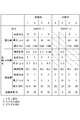
- FIG. 5 shows the thickness and hardness of the formed nitride layer 5 and DLC layer 7 and the thickness of the intermediate layer 6.
- Example 2 Example 2 was produced in the same manner as in Example 1 except that the conditions for forming the nitride layer 5, the intermediate layer 6, and the DLC layer 7 were changed.
- FIG. 5 shows the thickness and hardness of the formed nitride layer 5 and DLC layer 7 and the thickness of the intermediate layer 6.
- Example 3 Example 3 was produced in the same manner as in Example 2 except that the same base material 3 as in Example 2 was subjected to ion nitriding to form a nitrided layer 5.
- FIG. 5 shows the thickness and hardness of the formed nitride layer 5 and DLC layer 7 and the thickness of the intermediate layer 6.
- Example 4 It is manufactured in the same manner as in Example 2 except that the intermediate layer 6 made of Si 3 N 4 is formed on the surface of the nitride layer 5 formed on the surface of the same base material 3 as in Example 2 by the plasma CVD method. Example 4 was prepared.
- FIG. 5 shows the thickness and hardness of the formed nitride layer 5 and DLC layer 7 and the thickness of the intermediate layer 6.
- Comparative Example 1 Comparative Example 1 was obtained in the same manner as Example 1 except that the nitride layer 5 and the intermediate layer 6 were not provided. That is, in Comparative Example 1, the DLC layer 7 was formed on the surface of the same base material 3 as in Example 1 by the same method as in Example 1. The thickness and hardness of the formed DLC layer 7 are shown in FIG. (Comparative Example 2) An intermediate layer 6 made of SiC was formed on the same base material 3 as in Example 1 by the same method as in Example 1. A DLC layer 7 was formed on the surface of the formed intermediate layer 6 by the same method as in Example 1. The thickness and hardness of the DLC layer 7 and the thickness of the intermediate layer 6 are shown in FIG.
- Comparative Example 3 The same base material 3 as in Example 1 was subjected to radical nitridation treatment to form a nitride layer 5 on the surface of the base material 3. Comparative Example 3 was manufactured by forming the DLC layer 7 on the surface of the formed nitride layer 5 by plasma CVD. FIG. 5 shows the thickness and hardness of the formed nitride layer 5 and DLC layer 7. (Comparative Example 4) Comparative Example 4 was manufactured in the same manner as Comparative Example 3 except that the same base material 3 as in Example 1 was subjected to ion nitriding treatment by halving the nitriding treatment time to form a nitrided layer 5. . FIG. 5 shows the thickness and hardness of the formed nitride layer 5 and DLC layer 7.
- Example 1 to 4 and Comparative Examples 1 to 4 an evaluation test described below was performed.
- the evaluation results are shown in FIG. 3, FIG. 5 and FIG. [Evaluation 1: Evaluation of adhesion of laminated structure]
- a scratch test was performed under the following conditions to evaluate the adhesion of the laminated structure 1, particularly the DLC layer 7. Specifically, a chip (chip) is intentionally generated by pressing an indenter with a diamond tip at the tip against the surface of the fixed example and comparative example, and scratching while gradually increasing the applied load. It was. The point where the chip of Example and the comparative example occurred was read from the AE (Acoustic Emission) chart. From the result read from the AE chart, the adhesion was evaluated by the peel generation load (unit: N).
- Examples 1 to 4 have better adhesion than Comparative Examples 1 to 4, as shown in FIG.
- the adhesiveness of Examples 1 to 4 is that Comparative Example 1 in which the DLC layer 7 is formed on the surface of the base material 3 and the intermediate layer 6 is formed on the surface of the base material 3, and the DLC layer 7 is formed on the surface thereof.
- Comparative Example 2 suggests that the nitride layer 5 is formed.
- Comparative Example 3 and Comparative Example 4 in which the nitride layer 5 is formed on the surface of the base material 3 have a larger peeling load than Comparative Examples 1 and 2, but smaller than Examples 1 to 4.
- the nitride layer 5 on the surface of the base material 3 and further forming the intermediate layer 6 on the surface of the nitride layer 5, excellent adhesion can be obtained. It can be adjusted by changing the thickness and hardness. The adhesion also contributes to the improvement of erosion resistance.
- FIG. 4A shows a configuration diagram of the cavitation erosion test apparatus 80 used in this evaluation.
- the vibrator 81 is oscillated by the ultrasonic transmitter 86, the amplitude is enlarged by the horn 82, and the test piece A attached to the tip of the horn 82 as shown in FIG.
- An evaluation test was conducted by the method of vibrating Examples 5 to 8.
- the test piece A is fixed to the horn 82, is formed in a columnar shape, and the DLC layer 7 is disposed at the tip thereof.
- the tip of the test piece A was vibrated while being immersed in the test piece liquid 85 to generate bubbles, and erosion was generated by impact pressure and liquid jet when the bubbles collapsed.
- the test conditions are as follows. ⁇ Frequency: 18.5KHz ⁇ Amplitude: 25 ⁇ m ⁇ Test solution: Ion exchange water ⁇ Test specimen immersion depth: 5 mm ⁇ Test solution temperature: 20 ° C ⁇ Test time: 2 hours
- FIG. 6 shows the volume wear rate (unit: mm 3 / hr) of Examples 5 to 8 and Comparative Examples 5 to 7.
- Examples 5 to 8 have higher erosion resistance than Comparative Examples 5 to 7, the base material 3 and the nitride layer 5 are formed on the surface of the base material 3, and the surface of the nitride layer 5 is formed. It is suggested that high erosion resistance and fouling resistance can be obtained by forming the intermediate layer 6 and forming the DLC layer 7 on the surface of the intermediate layer 6.
- the laminated structure 1 having both erosion resistance and fouling resistance can be provided. Further, the thickness and hardness of the DLC layer 7 and the nitride layer 5 and the thickness of the intermediate layer 6 are adjusted in accordance with the type of the rotating machine component having the laminated structure 1 and the replacement period of the rotating machine component. In addition, the adhesion and erosion resistance can be adjusted by selecting the type of the intermediate layer 6.
- Applications of the laminated structure 1 of the present invention include, for example, rotating machine parts that are in direct contact with steam, such as blades and rotors used in rotating machines such as steam turbines. Further, there are a crankshaft, a synchronizer hub, a rocker arm, a rocker shaft valve, a valve guide, an impeller, a cylinder guide, a camshaft, etc., which are machine parts in the automobile and aircraft fields. Moreover, components such as an impeller, a rotor, a piston, a valve, a high pressure needle valve, a cylinder tube, and a cylinder rod of a compressor (compressor pump) that compresses various fluids used in a chemical plant or the like can be given.
- a compressor compressor
- gears such as a spur gear, a helical gear, and a worm & worm wheel, a shaft, a socket, and a cam
- various molds such as die casting, plastic, and aluminum extrusion, various tools such as a drill, a tap, and a cutter, and precision instrument parts such as a camera, a watch, and a sewing machine are included.
Landscapes
- Chemical & Material Sciences (AREA)
- Engineering & Computer Science (AREA)
- Mechanical Engineering (AREA)
- Materials Engineering (AREA)
- Metallurgy (AREA)
- Organic Chemistry (AREA)
- Chemical Kinetics & Catalysis (AREA)
- Inorganic Chemistry (AREA)
- General Engineering & Computer Science (AREA)
- General Chemical & Material Sciences (AREA)
- Ceramic Engineering (AREA)
- Chemical Vapour Deposition (AREA)
- Other Surface Treatments For Metallic Materials (AREA)
- Laminated Bodies (AREA)
- Details And Applications Of Rotary Liquid Pumps (AREA)
- Turbine Rotor Nozzle Sealing (AREA)
Abstract
耐エロージョン性と耐ファウリング性を両立させた積層構造、及び、そのような積層構造を備える回転機械用部品を提供する。本発明の積層構造1は、母材3の表面の上に、母材3を窒化処理することによって形成される窒化層5と、その窒化層5の窒化層の表面に形成される中間層6と、さらに中間層6の表面に形成されるDLC層(ダイヤモンドライクカーボン層)7と、を有することを特徴とする。積層構造1は、蒸気タービン等の回転機械に用いられる部品に適用することができる。
Description
本発明は、積層構造及び積層構造を有する機械部品に関する。
従来、例えば、蒸気タービンやコンプレッサポンプ等の回転機械に用いられるブレードを含む回転部品は、耐熱性や耐食性を考慮した表面処理が施されている。蒸気タービンは、作動流体である蒸気がタービンの動翼に噴射されて駆動されるものであり、動翼である蒸気タービンブレードやロータ等の回転機械の部品が、直接蒸気と接触する。また、化学プラントで用いられ、各種流体を圧縮する圧縮機であるコンプレッサポンプは、外部から動力を与えられたインペラが回転し、当該流体を圧縮する。このようなコンプレッサポンプにおいても、インペラやロータといった回転機械の部品が直接気体に接触する。
ここで、気体に含まれる水滴が高速で衝突する部品、例えば、蒸気タービンのブレードや、コンプレッサポンプのインペラにおいては、衝突する水滴によって表面にエロージョン(erosion)摩耗が発生する。エロージョン摩耗が生じると部品が振動し、この振動によって部品が破損するおそれがある。
また、上述のような回転機械に用いられる部品においては、気体中に含まれるセラミックス成分、例えばSiO2が付着する、所謂ファウリング(fouling)と呼ばれる現象が発生することがある。このように、部品にセラミック成分が付着した場合には、作動効率が低下するため、装置全体の効率が低下する。
エロージョン磨耗やファウリングを防止するための対策として、母材の表面に皮膜を形成することが広く検討されており、その中で、DLC(Diamond-Like Carbon:ダイヤモンドライクカーボン)膜を用いた皮膜が提案されている。
例えば、特許文献1は、気体が直接接する部位に表面平滑化皮膜を有する回転機械において、表面平滑化皮膜はその表面粗さの最大高さRyが1.0μmを超えない炭素層であるDLC層で形成することを提案している。特許文献1は、母材の表面に、例えば窒化クロム(CrN)からなる硬質窒化層を形成し、その表面に表面平滑化皮膜を形成することも提案している。
また、特許文献2及び特許文献3は、母材の表面上に、TiN、TiAlNなどの硬質皮膜と、フッ素を含有するDLC膜からなるファウリング防止膜とを順に積層することを提案している。
さらに、特許文献4は、金属母材に接着することができる接着ベース層と約Ra0.0254μm以下の表面粗さを有する上面層を含み、接着ベース層の少なくとも1つはダイヤモンドライクカーボンである多層コーティングを形成することを提案している。
例えば、特許文献1は、気体が直接接する部位に表面平滑化皮膜を有する回転機械において、表面平滑化皮膜はその表面粗さの最大高さRyが1.0μmを超えない炭素層であるDLC層で形成することを提案している。特許文献1は、母材の表面に、例えば窒化クロム(CrN)からなる硬質窒化層を形成し、その表面に表面平滑化皮膜を形成することも提案している。
また、特許文献2及び特許文献3は、母材の表面上に、TiN、TiAlNなどの硬質皮膜と、フッ素を含有するDLC膜からなるファウリング防止膜とを順に積層することを提案している。
さらに、特許文献4は、金属母材に接着することができる接着ベース層と約Ra0.0254μm以下の表面粗さを有する上面層を含み、接着ベース層の少なくとも1つはダイヤモンドライクカーボンである多層コーティングを形成することを提案している。
ところが、本発明者らの検討によると、以下の通りである。
はじめに、特許文献1は、DLC膜と硬質窒化層の密着性が不十分であり、特許文献2及び特許文献3も、フッ素含有DLC膜と硬質皮膜の密着性が不十分である。
また、特許文献4は、最上層のDLC層にドレンが衝突すると、その衝撃が母材にまで及んでしまい、母材に微小なへこみが生じ、DLC層がこのへこみに追従できずに、DLC層に亀裂が生ずるおそれがある。そうすると、DLC層が剥離してしまう。
はじめに、特許文献1は、DLC膜と硬質窒化層の密着性が不十分であり、特許文献2及び特許文献3も、フッ素含有DLC膜と硬質皮膜の密着性が不十分である。
また、特許文献4は、最上層のDLC層にドレンが衝突すると、その衝撃が母材にまで及んでしまい、母材に微小なへこみが生じ、DLC層がこのへこみに追従できずに、DLC層に亀裂が生ずるおそれがある。そうすると、DLC層が剥離してしまう。
以上より、本発明は、DLC層の密着性を向上するとともに、耐エロージョン性及び耐ファウリング性を確保できる積層構造を提供することを目的とする。また、本発明は、そのような積層構造を備える回転機械用部品を提供とすることを目的とする。
本発明の積層構造は、鉄系の金属材料からなる母材と、母材を窒化処理することによって、母材の表面に形成される窒化層と、窒化層の表面に形成される中間層と、中間層の表面に形成されるDLC層と、を備えることを特徴とする。
本発明の積層構造は、窒化層が、母材とDLC層の中間の硬さを有し、母材からDLC層に向けて、連続的に硬さが高くなることが好ましい。
本発明の積層構造は、窒化層の厚さが10~100μmであることが好ましい。また、本発明の積層構造は、窒化層の厚さが25~80μmであることがより好ましい。
本発明の積層構造は、窒化層と母材との界面に、母材に窒素が拡散した拡散層が設けられることが好ましい。
本発明の積層構造は、窒化層と母材との界面に、母材に窒素が拡散した拡散層が設けられることが好ましい。
本発明の積層構造は、中間層の厚さが0.5~2μmであることが好ましい。
本発明の積層構造は、中間層がSiC及びSi3N4の一種又は二種からなることが好ましい。
本発明の積層構造は、中間層が窒化層より硬いこともあれば、DLC層よりも硬いこともある。
本発明の積層構造は、中間層がSiC及びSi3N4の一種又は二種からなることが好ましい。
本発明の積層構造は、中間層が窒化層より硬いこともあれば、DLC層よりも硬いこともある。
本発明の積層構造は、DLC層の厚さが1~10μmであることが好ましい。
以上説明した本発明の積層構造は、回転機械用部品に適用され、とりわけ蒸気タービン又はコンプレッサの部品に適用されるのが好ましい。
本発明の積層構造は、母材を窒化処理することによって母材の表面に窒化層を設け、その窒化層の上に中間層を設け、その中間層の上にDLC層を形成した積層構造を有するものである。本発明の積層構造は、窒化層及び中間層を介在させることで、DLC層に加えられた内部応力が緩和されるので、DLC層にドレンが衝突して衝撃が加わっても、DLC層に剥がれや割れが起こり難く、密着性の優れた積層構造にすることができる。また、DLC層は、耐エロージョン性を備えるとともに、それ自体の表面エネルギが小さいために、十分な耐ファウリング性を有している。つまり、本発明の積層構造を採用することにより、密着性が優れるとともに、耐エロージョン性と耐ファウリング性を兼ね備えた回転機械用部品を提供することができる。
以下、添付図面を参照しながら、本発明の実施形態について説明する。
本実施形態に係る積層構造1は、図1に示すように、母材3と、母材3の表面に形成される窒化層5と、窒化層5の表面に形成される中間層6と、中間層6の表面に形成されるDLC層7と、を有し、後述する回転機械に適用されることで、耐エロージョン性及び耐ファウリング性を発揮する。
積層構造1は、母材3の表面を窒化して形成される窒化層5と中間層6を介してDLC層7を積層することで、DLC層7の密着性を向上させる。
以下、母材3、窒化層5及びDLC層7の順に説明し、その後、積層構造1を評価した結果を説明する。
本実施形態に係る積層構造1は、図1に示すように、母材3と、母材3の表面に形成される窒化層5と、窒化層5の表面に形成される中間層6と、中間層6の表面に形成されるDLC層7と、を有し、後述する回転機械に適用されることで、耐エロージョン性及び耐ファウリング性を発揮する。
積層構造1は、母材3の表面を窒化して形成される窒化層5と中間層6を介してDLC層7を積層することで、DLC層7の密着性を向上させる。
以下、母材3、窒化層5及びDLC層7の順に説明し、その後、積層構造1を評価した結果を説明する。
[母材3]
積層構造1の母材3は、回転機械の各種部品を構成する鉄系の金属材料からなる。母材3の例としては、SUS403やSUS410J1に代表されるマルテンサイト系ステンレス鋼、SUS301やSUS301J1に代表されるオーステナイト系ステンレス鋼、SUS430やSUS410Lに代表されるフェライト系ステンレス鋼、SUS329J1に代表される二相ステンレス鋼、SUS630に代表される析出軟化系ステンレス鋼、等がある。この他にも、回転機械において一般に用いられている鉄系の金属材料にも制限なく適用することができる。
母材3は、用いる金属材料により異なるが、上述したステンレス鋼であれば、概ねビッカース硬さ(Hv)で200~500の硬さを有する。本実施形態における母材3は、その表面に形成された窒化層5を除いた部分をいう。
なお、硬さHv及びその測定手順は、後述する実施例も含めてJIS Z 2244に準拠する。
積層構造1の母材3は、回転機械の各種部品を構成する鉄系の金属材料からなる。母材3の例としては、SUS403やSUS410J1に代表されるマルテンサイト系ステンレス鋼、SUS301やSUS301J1に代表されるオーステナイト系ステンレス鋼、SUS430やSUS410Lに代表されるフェライト系ステンレス鋼、SUS329J1に代表される二相ステンレス鋼、SUS630に代表される析出軟化系ステンレス鋼、等がある。この他にも、回転機械において一般に用いられている鉄系の金属材料にも制限なく適用することができる。
母材3は、用いる金属材料により異なるが、上述したステンレス鋼であれば、概ねビッカース硬さ(Hv)で200~500の硬さを有する。本実施形態における母材3は、その表面に形成された窒化層5を除いた部分をいう。
なお、硬さHv及びその測定手順は、後述する実施例も含めてJIS Z 2244に準拠する。
[窒化層5]
窒化層5は、後述するDLC層7の密着性の向上と、ドレンが衝突することによる衝撃を緩衝するために形成される。
窒化層5は、母材3の主成分である鉄(Fe)の窒化物を主体とする化合物からなるが、母材3との界面には窒素が拡散した拡散層が形成される。
窒化層5は、母材3とDLC層7の間に介在し、その硬さが母材3とDLC層7の中間の値を示すが、母材3を窒化処理して得られるものである。したがって、窒化層5の拡散層は、母材3との界面付近で母材3と同等の硬さを有し、母材3の上に形成された窒化物に比べて、母材3に対する密着性が高い。
窒化層5は、後述するDLC層7の密着性の向上と、ドレンが衝突することによる衝撃を緩衝するために形成される。
窒化層5は、母材3の主成分である鉄(Fe)の窒化物を主体とする化合物からなるが、母材3との界面には窒素が拡散した拡散層が形成される。
窒化層5は、母材3とDLC層7の間に介在し、その硬さが母材3とDLC層7の中間の値を示すが、母材3を窒化処理して得られるものである。したがって、窒化層5の拡散層は、母材3との界面付近で母材3と同等の硬さを有し、母材3の上に形成された窒化物に比べて、母材3に対する密着性が高い。
窒化層5は、母材3が局部的に変形するのを防止するために設けられ、母材3とDLC層7の中間の硬さを有する。もっとも、後述するように、窒化層5は、その硬さが母材3からDLC層7に向けて連続的に高くなる傾斜構造を有しており、具体的な硬さは、窒化処理する母材3の材質により定まるものであり、例えば、SUS410J1が母材3を構成するものとすると、窒化層5の厚さ方向と直交する断面方向から硬さを測定した場合に、400~1200Hv程度である。後述するように、窒化層5は、その硬さが母材3からDLC層7に向けて連続的に高くなる傾斜構造を有しており、その硬さは厚さ方向において変動する。
窒化層5は、母材3の表面を後述する方法で窒化処理することにより、母材3の当初の表面から厚さ方向に形成されるものである。窒化層5は、窒化処理を施す時間、その他の条件によって、図2の一点鎖線のように厚さを厚くしたり、逆に図2の実線のように厚さを薄くしたり調整することができる。窒化層5が薄すぎると、窒化層5を設けることによる効果を十分に得られないことがある。また、窒化層5を必要以上に厚くしても、その効果は飽和する一方、処理時間が長くなり経済性を損ねる。これらのことを考慮すると、窒化層5は、厚さを10~100μmとするのが好ましく、20~90μmとするのがより好ましく、25~80μmとするのがさらに好ましい。
なお、窒化層5の厚さは、前述した拡散層を含む厚さで定義され(JIS B 6905)、後述する実施例の厚さの測定も同様である。窒化層5は、拡散層を有することにより、図2に示すように、DLC層7の表面71から厚さ方向に硬度が低くなる傾斜構造になっている。
なお、窒化層5の厚さは、前述した拡散層を含む厚さで定義され(JIS B 6905)、後述する実施例の厚さの測定も同様である。窒化層5は、拡散層を有することにより、図2に示すように、DLC層7の表面71から厚さ方向に硬度が低くなる傾斜構造になっている。
窒化層5を介在させないで、母材3の表面にDLC層7を形成させると、母材3とDLC層7の硬さの差が大きいために、ドレンが衝突することによりDLC層7に発生する衝撃が母材3に直接的に伝わり、硬さの低い母材3がドレン衝突に対応して局部的に変形する。そうすると、DLC層7にも変形が生じて、DLC層7に割れや剥離が生じやすい。これに対し、母材3よりも硬い窒化層5が母材3の表面に形成されて、母材3とDLC層7との間に介在すると、DLC層7にドレンが衝突しても、窒化層5がその衝撃に抵抗するので、DLC層7に加わった衝撃を窒化層5が緩和するので、母材3の変形を抑えることができる。このように、窒化層5は、DLC層7に割れや剥離が生じるのを抑制する。つまり、窒化層5は応力緩和によって、DLC層7の密着性を向上させる。
さらに、窒化層5が、母材3からDLC層7の方向に連続的に硬さを上昇させる傾斜構造であることから、せん断力に対し急激な形状の変化を防ぐことができる。これにより、窒化層5は応力集中を抑制することが可能であり、DLC層7の割れを防止できる。
さらに、窒化層5が、母材3からDLC層7の方向に連続的に硬さを上昇させる傾斜構造であることから、せん断力に対し急激な形状の変化を防ぐことができる。これにより、窒化層5は応力集中を抑制することが可能であり、DLC層7の割れを防止できる。
[窒化層5の形成方法]
窒化層5を形成する手段は任意であり、公知の窒化処理を適用できる。窒化処理としては、イオン窒化処理及びラジカル窒化処理が適用できる。
窒化層5を形成する手段は任意であり、公知の窒化処理を適用できる。窒化処理としては、イオン窒化処理及びラジカル窒化処理が適用できる。
イオン窒化は、減圧された真空炉槽中に母材3を陰極、炉体を陽極にして、炉内に窒素と水素を反応ガスとして導入して数百ボルトの直流電圧を印加すると陰極側でグロー放電を生じさせる。これによって+(プラス)に帯電した窒素イオンと水素イオンは、陰極である母材3に衝突するが、この衝突によって母材3は昇温し、窒化物が生成され母材3の内部に拡散して、窒化層5が形成される。プラズマ窒化処理によって形成される窒化層5の厚さは、処理温度、バイアス電圧、処理時間、水素ガスに対する窒素ガスの分圧比を変えることによって調整することができる。
ラジカル窒化処理は、プラズマ窒化法の一種であり、炉内にアンモニアガスと水素ガスの混合ガスを導入して、炉体と母材3の間にグロー放電を生じさせ、プラズマ中の窒素イオンを母材3の金属と反応させて表に窒化層5を形成するものである。ラジカル窒化処理によって形成される窒化層5の厚さは、処理温度、バイアス電圧、処理時間、水素ガスとアンモニアガスの分圧比を変えることによって調整することができる。
[中間層6]
中間層6は、上述した窒化層5の表面に形成される。窒化層5とともにDLC層7の密着性を向上させるためのものである。
中間層6は、SiC(炭化ケイ素)、Si3N4(窒化ケイ素)及びSiCN(炭窒化ケイ素)の何れか一種、又は、二種以上の層が積層化されている。これらのうち、SiC及びSi3N4の一種、又は、二種の層が積層化されるものが好ましい。
中間層6の硬さは、中間層6がSiC、Si3N4及びSiCNの何れからなるかにより異なる。例えば、中間層6がSiCからなる場合は、硬さが2000~2200Hv程度であり、図2に示すように、窒化層5より硬くすることができる。一方、中間層6がSi3N4からなる場合は、硬さを1400~1600Hv程度にすることができる。なお、上述したSiCからなる中間層6の硬さは、中間層6の厚さ方向と直交する断面方向からナノインデンテーション(Nano Indentation)で測定したナノインデンテーション硬さを、ビッカース硬さに換算したものである。
なお、中間層6の硬さは、後述する実施例においても断面方向から測定しているが、中間層6の表面が特定される場合には、DLC層7が中間層6の表面に積層されているか否かに関わらず、中間層6の表面と直交する表面方向から測定することも可能である。
中間層6は、上述した窒化層5の表面に形成される。窒化層5とともにDLC層7の密着性を向上させるためのものである。
中間層6は、SiC(炭化ケイ素)、Si3N4(窒化ケイ素)及びSiCN(炭窒化ケイ素)の何れか一種、又は、二種以上の層が積層化されている。これらのうち、SiC及びSi3N4の一種、又は、二種の層が積層化されるものが好ましい。
中間層6の硬さは、中間層6がSiC、Si3N4及びSiCNの何れからなるかにより異なる。例えば、中間層6がSiCからなる場合は、硬さが2000~2200Hv程度であり、図2に示すように、窒化層5より硬くすることができる。一方、中間層6がSi3N4からなる場合は、硬さを1400~1600Hv程度にすることができる。なお、上述したSiCからなる中間層6の硬さは、中間層6の厚さ方向と直交する断面方向からナノインデンテーション(Nano Indentation)で測定したナノインデンテーション硬さを、ビッカース硬さに換算したものである。
なお、中間層6の硬さは、後述する実施例においても断面方向から測定しているが、中間層6の表面が特定される場合には、DLC層7が中間層6の表面に積層されているか否かに関わらず、中間層6の表面と直交する表面方向から測定することも可能である。
中間層6を窒化層5とDLC層7の間に介在させることで、DLC層7の構成成分である炭素と窒化層5の構成成分である窒素の存在により、DLC層7の密着性の向上を通じてDLC層7の耐エロージョン性が向上する。
中間層6は、後述する中間層6の形成方法において、適宜条件を設定することにより、所望の厚さにすることができるが、厚さは0.5~2μmであることが好ましい。
[中間層6の形成方法]
中間層6を形成する手段は、イオン窒化処理又はラジカル窒化処理に継続して、プラズマ処理で行われる。
中間層6を形成する手段は、イオン窒化処理又はラジカル窒化処理に継続して、プラズマ処理で行われる。
窒化層5がイオン窒化により形成されており、SiCからなる中間層6を形成させる場合は、まず、真空炉槽中の窒化処理時に導入された窒素と水素を徐々に低下させるとともに、真空炉槽中に、Si系ガス(例えば、ヘキサメチルジシロキサンのガス)と、DLCの原料ガス(例えば、アセチレンのガス)を導入する。そして、SiCからなる中間層6は、真空炉槽中にSi系ガスとDLCの原料ガスが存在している状態で、窒化層5が形成されている母材3にプラズマ処理を行うことにより成膜される。
また、Si3N4からなる中間層6は、真空炉槽中にSi系ガス(例えば、ヘキサメチルジシロキサンのガス)を導入して、真空炉槽中に、Si系ガスと窒化処理時に導入された窒素が存在する状態で、窒化層5が形成されている母材3にプラズマ処理を行うことにより成膜される。
さらに、SiCNからなる中間層6は、真空炉槽中に、Si系ガス(例えば、ヘキサメチルジシロキサンのガス)と、DLCの原料ガス(例えば、アセチレンのガス)を導入して、真空炉槽中に、Si系ガスとDLCの原料ガスと窒化処理時に導入された窒素が存在する状態で、窒化層5が形成されている母材3にプラズマ処理を行うことにより成膜される。
また、Si3N4からなる中間層6は、真空炉槽中にSi系ガス(例えば、ヘキサメチルジシロキサンのガス)を導入して、真空炉槽中に、Si系ガスと窒化処理時に導入された窒素が存在する状態で、窒化層5が形成されている母材3にプラズマ処理を行うことにより成膜される。
さらに、SiCNからなる中間層6は、真空炉槽中に、Si系ガス(例えば、ヘキサメチルジシロキサンのガス)と、DLCの原料ガス(例えば、アセチレンのガス)を導入して、真空炉槽中に、Si系ガスとDLCの原料ガスと窒化処理時に導入された窒素が存在する状態で、窒化層5が形成されている母材3にプラズマ処理を行うことにより成膜される。
窒化層5がラジカル窒化により形成されており、SiCからなる中間層6を形成させる場合は、まず、真空炉槽中の窒化処理時のアンモニアと水素ガスを徐々に低下させるとともに、真空炉槽中に、Si系ガス(例えばヘキサメチルジシロキサンのガス)とDLCの原料ガス(例えば、アセチレンのガス)を導入する。そして、SiCからなる中間層6は、真空炉槽中にSi系ガスとDLCの原料ガスが存在している状態で、窒化層5が形成されている母材3にプラズマ処理を行うことにより成膜される。
また、Si3N4からなる中間層6は、真空炉槽中に、Si系ガス(例えばヘキサメチルジシロキサンのガス)を導入して、真空炉槽中に、Si系ガスと窒化処理時に導入されたアンモニアガスが存在する状態で、窒化層5が形成されている母材3にプラズマ処理を行うことにより成膜される。
さらに、SiCNからなる中間層6は、真空炉槽中に、Si系ガス(例えばヘキサメチルジシロキサンのガス)とDLCの原料ガス(例えば、アセチレンのガス)を導入して、真空炉槽中に、Si系ガスとDLCの原料ガスと窒化処理時に導入されたアンモニアガスが存在する状態で、窒化層5が形成されている母材3にプラズマ処理を行うことにより成膜される。
また、Si3N4からなる中間層6は、真空炉槽中に、Si系ガス(例えばヘキサメチルジシロキサンのガス)を導入して、真空炉槽中に、Si系ガスと窒化処理時に導入されたアンモニアガスが存在する状態で、窒化層5が形成されている母材3にプラズマ処理を行うことにより成膜される。
さらに、SiCNからなる中間層6は、真空炉槽中に、Si系ガス(例えばヘキサメチルジシロキサンのガス)とDLCの原料ガス(例えば、アセチレンのガス)を導入して、真空炉槽中に、Si系ガスとDLCの原料ガスと窒化処理時に導入されたアンモニアガスが存在する状態で、窒化層5が形成されている母材3にプラズマ処理を行うことにより成膜される。
[DLC層7]
次に、DLC層7について説明する。
DLC層7は、窒化層5の表面に形成され、積層構造1の最表面(最表層)に位置することで、積層構造1に耐エロージョン性及び耐ファウリング性を付与する。
DLC(Diamond Like Carbon)は、結晶構造が六方晶のグラファイトと立方晶のダイヤモンドの中間的な物性をもつ非晶質のカーボン膜であり、硬さがHvで1000~5000の範囲を示す硬質膜である。同じDLCでも硬さに範囲があるのは、主にDLCの構成元素の相違による。つまり、DLCは、大きく分けると、構成元素が炭素と水素からなるものと、炭素のみからなるものに区分され、この差は、DLCを成膜する際の製法の違いによる。さらに、水素を含有するDLCでも水素含有量の違いで、硬さ、その他の性質が相違する。一般に、DLC層は、水素含有量を減らすことによって硬さを増加させる方向に制御することができる。
次に、DLC層7について説明する。
DLC層7は、窒化層5の表面に形成され、積層構造1の最表面(最表層)に位置することで、積層構造1に耐エロージョン性及び耐ファウリング性を付与する。
DLC(Diamond Like Carbon)は、結晶構造が六方晶のグラファイトと立方晶のダイヤモンドの中間的な物性をもつ非晶質のカーボン膜であり、硬さがHvで1000~5000の範囲を示す硬質膜である。同じDLCでも硬さに範囲があるのは、主にDLCの構成元素の相違による。つまり、DLCは、大きく分けると、構成元素が炭素と水素からなるものと、炭素のみからなるものに区分され、この差は、DLCを成膜する際の製法の違いによる。さらに、水素を含有するDLCでも水素含有量の違いで、硬さ、その他の性質が相違する。一般に、DLC層は、水素含有量を減らすことによって硬さを増加させる方向に制御することができる。
本実施形態におけるDLC層7は、硬さが低い場合も逆に高い場合も耐エロージョン性が劣る傾向にある。
DLC層7の硬さは、薄膜の硬度測定に適用されるナノインデンテーションにより特定することができる。後述する実施例に示すように、耐エロージョン性を評価する上で、ナノインデンテーション硬さが有効だからである。具体的には、DLC層7の表面と直交する表面方向から硬さを測定した場合に、DLC層7のナノインデンテーション硬さは、13~30GPaであることが好ましく、14~27GPaであることがより好ましく、15~25GPaであることがさらに好ましい。
なお、DLC層7の硬さは、後述する実施例においても表面方向から測定しているが、DLC層7の厚さ方向と直交する断面方向から測定することも可能である。
DLC層7の硬さは、薄膜の硬度測定に適用されるナノインデンテーションにより特定することができる。後述する実施例に示すように、耐エロージョン性を評価する上で、ナノインデンテーション硬さが有効だからである。具体的には、DLC層7の表面と直交する表面方向から硬さを測定した場合に、DLC層7のナノインデンテーション硬さは、13~30GPaであることが好ましく、14~27GPaであることがより好ましく、15~25GPaであることがさらに好ましい。
なお、DLC層7の硬さは、後述する実施例においても表面方向から測定しているが、DLC層7の厚さ方向と直交する断面方向から測定することも可能である。
DLC層7は、後述する積層構造1を有する回転機械用部品の交換の期間を考慮して厚さを設定できるが、その厚さは、1~10μmであることが好ましく、1~8μmであることがより好ましく、2~5μmであることがさらに好ましい。
[DLC層7の形成方法]
所望するDLC層7が形成される限り、DLC層7を形成する手段は任意であり、公知のDLCの成膜方法を適用できる。
DLCの成膜方法は、固体の炭素からスパッタリングや陰極アーク放電を利用して成膜するPVD法(Physical Vapor Deposition,物理気相成長法)と、CVD法(Chemical Vapor Deposition,化学気相成長法)の2種に大別される。さらに、CVD法は、成分元素を分子状にガス化し化学反応によって成膜する熱CVD法と、メタン(CH4)やアセチレン(C2H2)等の炭化水素系ガスをプラズマ化して成膜するプラズマCVD法、等がある。プラズマCVD法は、熱CVD法に比べて処理温度を低くできる利点がある。
所望するDLC層7が形成される限り、DLC層7を形成する手段は任意であり、公知のDLCの成膜方法を適用できる。
DLCの成膜方法は、固体の炭素からスパッタリングや陰極アーク放電を利用して成膜するPVD法(Physical Vapor Deposition,物理気相成長法)と、CVD法(Chemical Vapor Deposition,化学気相成長法)の2種に大別される。さらに、CVD法は、成分元素を分子状にガス化し化学反応によって成膜する熱CVD法と、メタン(CH4)やアセチレン(C2H2)等の炭化水素系ガスをプラズマ化して成膜するプラズマCVD法、等がある。プラズマCVD法は、熱CVD法に比べて処理温度を低くできる利点がある。
本実施形態におけるDLC層7は、PVD法及びCVD法のいずれによっても形成できるが、適用する回転機械用部品によっては、PVD法よりもCVD法によりDLC層7を形成することが好ましい。つまり、特に、プラズマCVD法は、狭小空間でもつきまわり性が良好であり、コンプレッサのダイヤフラム、クローズドインペラ内部、蒸気タービンの仕切板などの狭隘な空間を有する部品に成膜するのに好適である。
この際に、プラズマを生成させる方法としてはECR(Electron Cyclotron Resonance:電子サイクロトロン共鳴)プラズマや、マイクロ波を内面に沿って伝搬させて内面で高密度プラズマを作用させるMVP(Microwave-sheath Voltage combination Plasma)を適用できる。
この際に、プラズマを生成させる方法としてはECR(Electron Cyclotron Resonance:電子サイクロトロン共鳴)プラズマや、マイクロ波を内面に沿って伝搬させて内面で高密度プラズマを作用させるMVP(Microwave-sheath Voltage combination Plasma)を適用できる。
本実施形態のDLC層7は、表面エネルギが小さいために、セラミックス成分が付着しにくい性質を有するので、フッ素を含有しなくても、耐ファウリング性に優れている。
上記のように構成される本実施形態の積層構造1は、母材3と、母材3の表面に形成される窒化層5と、窒化層5の表面に形成される中間層6と、中間層6の表面に形成されるDLC層7と、を有し、後述する回転機械用部品に適用されることで、耐エロージョン性及び耐ファウリング性を発揮する。
積層構造1は、図2に示す硬さの分布を示す。積層構造1は、母材3が図2の横軸で示される厚さ方向において、ほぼ等しい硬さを有するが、窒化層5は母材3のとの境界から中間層6との境界に向けて硬さが上昇する。窒化層5は、母材3を窒化して形成されたものであるから、母材3と窒化層5はその境界において、硬さが連続性を有している。一方、中間層6は窒化層5の表面に形成されたものであり、DLC層7は中間層6の表面に形成されたものであるから、窒化層5と中間層6の境界における硬さ、及び、中間層6とDLC層7の境界における硬さが不連続である。
積層構造1は、硬さに相当の差がある母材3とDLC層7の間に、両者の中間の硬さを有する窒化層5を備えている。したがって、ドレンが衝突してDLC層7に衝撃が生じても、窒化層5が緩衝となり衝撃が母材3に伝わるのを阻止するか、少なくとも軽減するので、母材3に局部的な変形が生じるのを抑制する。
また、中間層6により、DLC層7の密着性が向上することにより耐エロージョン性が向上する。
また、中間層6により、DLC層7の密着性が向上することにより耐エロージョン性が向上する。
母材3の材質や、積層構造1が適用される回転機械用部品が用いられる環境によって、窒化層5及びDLC層7の、相互の厚さと硬さを適宜調整することができる。なお、窒化層5は、DLC層7よりも厚くなっていることが好ましい。具体的には、窒化層5の厚さとDLC層7の厚さの比は、10:1~100:1であることが好ましく、10:1~90:1であることがより好ましく、12:1~40:1であることが特に好ましい。
以下、本発明を具体的な実施例を挙げて詳細に説明する。ただし、本発明は以下に示す実施例に限定されるものではない。
以下に示す実施例1~実施例4、及び、比較例1~比較例4による積層構造を作製し、窒化層5、中間層6及びDLC層7の厚さ及び硬さを測定するとともに、DLC層7の密着性の評価(評価1)と、実施例5~実施例8による積層構造を作製し、耐ドレンエロージョン性の評価(評価2)を行った。
以下に示す実施例1~実施例4、及び、比較例1~比較例4による積層構造を作製し、窒化層5、中間層6及びDLC層7の厚さ及び硬さを測定するとともに、DLC層7の密着性の評価(評価1)と、実施例5~実施例8による積層構造を作製し、耐ドレンエロージョン性の評価(評価2)を行った。
(実施例1)
JIS SUS410J1からなる母材3を、ラジカル窒化処理を行うことにより、母材3の表面に窒化層5を形成した。形成された窒化層5の表面に、プラズマCVD法により、SiCからなる中間層6を形成した。そして、形成された中間層6の表面に、プラズマCVD法により、DLC層7を形成して実施例1を製造した。この積層構造1は、母材3の表面から、窒化層5、中間層6及びDLC層7の順に積層されている。形成させた窒化層5及びDLC層7の厚さと硬さと、中間層6の厚さを図5に示す。
JIS SUS410J1からなる母材3を、ラジカル窒化処理を行うことにより、母材3の表面に窒化層5を形成した。形成された窒化層5の表面に、プラズマCVD法により、SiCからなる中間層6を形成した。そして、形成された中間層6の表面に、プラズマCVD法により、DLC層7を形成して実施例1を製造した。この積層構造1は、母材3の表面から、窒化層5、中間層6及びDLC層7の順に積層されている。形成させた窒化層5及びDLC層7の厚さと硬さと、中間層6の厚さを図5に示す。
(実施例2)
窒化層5、中間層6及びDLC層7を形成させるための条件を変えたこと以外は、実施例1と同様に製造して実施例2を製造した。形成させた窒化層5及びDLC層7の厚さ及び硬さと、中間層6の厚さを図5に示す。
窒化層5、中間層6及びDLC層7を形成させるための条件を変えたこと以外は、実施例1と同様に製造して実施例2を製造した。形成させた窒化層5及びDLC層7の厚さ及び硬さと、中間層6の厚さを図5に示す。
(実施例3)
実施例2と同じ母材3に、イオン窒化処理を行って窒化層5を形成した以外は、実施例2と同様にして実施例3を製造した。形成させた窒化層5及びDLC層7の厚さ及び硬さと、中間層6の厚さを図5に示す。
実施例2と同じ母材3に、イオン窒化処理を行って窒化層5を形成した以外は、実施例2と同様にして実施例3を製造した。形成させた窒化層5及びDLC層7の厚さ及び硬さと、中間層6の厚さを図5に示す。
(実施例4)
実施例2と同じ母材3の表面に形成された窒化層5の表面に、プラズマCVD法により、Si3N4からなる中間層6を形成した以外は、実施例2と同様に製造して実施例4を製造した。形成させた窒化層5及びDLC層7の厚さ及び硬さと、中間層6の厚さを図5に示す。
実施例2と同じ母材3の表面に形成された窒化層5の表面に、プラズマCVD法により、Si3N4からなる中間層6を形成した以外は、実施例2と同様に製造して実施例4を製造した。形成させた窒化層5及びDLC層7の厚さ及び硬さと、中間層6の厚さを図5に示す。
(比較例1)
窒化層5及び中間層6を設けないこと以外は、実施例1と同様にして比較例1を得た。つまり、比較例1は、実施例1と同じ母材3の表面に、実施例1と同様の方法により、DLC層7を形成した。形成されたDLC層7の厚さと硬さを図5に示す。
(比較例2)
実施例1と同じ母材3に、実施例1と同じ方法で、SiCからなる中間層6を形成した。形成された中間層6の表面に、実施例1と同じ方法で、DLC層7を形成した。DLC層7の厚さ及び硬さと、中間層6の厚さを図5に示す。
窒化層5及び中間層6を設けないこと以外は、実施例1と同様にして比較例1を得た。つまり、比較例1は、実施例1と同じ母材3の表面に、実施例1と同様の方法により、DLC層7を形成した。形成されたDLC層7の厚さと硬さを図5に示す。
(比較例2)
実施例1と同じ母材3に、実施例1と同じ方法で、SiCからなる中間層6を形成した。形成された中間層6の表面に、実施例1と同じ方法で、DLC層7を形成した。DLC層7の厚さ及び硬さと、中間層6の厚さを図5に示す。
(比較例3)
実施例1と同じ母材3を、ラジカル窒化処理を行うことにより、母材3の表面に窒化層5を形成した。形成された窒化層5の表面に、プラズマCVD法により、DLC層7を形成して比較例3を製造した。形成された窒化層5とDLC層7の厚さ及び硬さを図5に示す。
(比較例4)
実施例1と同じ母材3を、窒化処理を行う処理時間を半分にしてイオン窒化処理を行って窒化層5を形成した以外は、比較例3と同様に製造して比較例4を製造した。形成された窒化層5とDLC層7の厚さ及び硬さを図5に示す。
実施例1と同じ母材3を、ラジカル窒化処理を行うことにより、母材3の表面に窒化層5を形成した。形成された窒化層5の表面に、プラズマCVD法により、DLC層7を形成して比較例3を製造した。形成された窒化層5とDLC層7の厚さ及び硬さを図5に示す。
(比較例4)
実施例1と同じ母材3を、窒化処理を行う処理時間を半分にしてイオン窒化処理を行って窒化層5を形成した以外は、比較例3と同様に製造して比較例4を製造した。形成された窒化層5とDLC層7の厚さ及び硬さを図5に示す。
実施例1~4及び比較例1~4を用いて、以下に説明する評価試験を実施した。評価結果を図3、図5及び図6に示す。
[評価1:積層構造の密着性評価]
以下の条件で、スクラッチ試験を行い、積層構造1の特にDLC層7の密着性を評価した。
具体的には、固定した実施例及び比較例の表面に対し、先端にダイヤモンドチップが備わった圧子を押し付け、印加する荷重を徐々に大きくしながら引っ掻くことで意図的にカケ(Chipping)を生じさせた。実施例及び比較例のカケが生じた点をAE(Acoustic Emission)チャートから読み取った。AEチャートから読み取った結果より、剥離発生荷重(単位:N)によって密着性を評価した。その評価結果を図3及び図5に示す。密着性は、剥離発生荷重(N)が大きいほど高くなる。
・装置:AEセンサー付き自動スクラッチ試験機(CSM Instruments社製)
・直動試料テーブル移動速度:10mm/min
・荷重負荷レート:100N/min(=10N/mm)
[評価1:積層構造の密着性評価]
以下の条件で、スクラッチ試験を行い、積層構造1の特にDLC層7の密着性を評価した。
具体的には、固定した実施例及び比較例の表面に対し、先端にダイヤモンドチップが備わった圧子を押し付け、印加する荷重を徐々に大きくしながら引っ掻くことで意図的にカケ(Chipping)を生じさせた。実施例及び比較例のカケが生じた点をAE(Acoustic Emission)チャートから読み取った。AEチャートから読み取った結果より、剥離発生荷重(単位:N)によって密着性を評価した。その評価結果を図3及び図5に示す。密着性は、剥離発生荷重(N)が大きいほど高くなる。
・装置:AEセンサー付き自動スクラッチ試験機(CSM Instruments社製)
・直動試料テーブル移動速度:10mm/min
・荷重負荷レート:100N/min(=10N/mm)
実施例1~4は、図3に示すように、比較例1~4よりも優れた密着性を有している。
実施例1~4の密着性は、母材3の表面にDLC層7が形成された比較例1、及び母材3の表面に中間層6が形成され、その表面にDLC層7が形成された比較例2との対比から、窒化層5が形成されていることによるものであることが示唆される。一方、母材3の表面に窒化層5が形成されている比較例3及び比較例4は、剥離荷重が、比較例1及び比較例2よりも大きいが、実施例1~4よりも小さい。
このように、母材3の表面に窒化層5させ、さらに窒化層5の表面に中間層6を形成させることにより、優れた密着性を得ることができ、さらにその密着性を窒化層5の厚さや硬さを変更することで調節することができる。
なお、密着性は、耐エロージョン性の向上にも寄与している。
実施例1~4の密着性は、母材3の表面にDLC層7が形成された比較例1、及び母材3の表面に中間層6が形成され、その表面にDLC層7が形成された比較例2との対比から、窒化層5が形成されていることによるものであることが示唆される。一方、母材3の表面に窒化層5が形成されている比較例3及び比較例4は、剥離荷重が、比較例1及び比較例2よりも大きいが、実施例1~4よりも小さい。
このように、母材3の表面に窒化層5させ、さらに窒化層5の表面に中間層6を形成させることにより、優れた密着性を得ることができ、さらにその密着性を窒化層5の厚さや硬さを変更することで調節することができる。
なお、密着性は、耐エロージョン性の向上にも寄与している。
[評価2:耐ドレンエロージョン性の評価]
積層構造1の耐ドレンエロージョン性の評価をするため、実施例5~8に係る積層構造1を、実施例1~4の層構成になるように作製し、JIS R 1646(ASTM G32-77)に準じて、キャビテーションエロージョン試験を行った。また、評価1で用いた比較例2~3の層構成で作成した比較例5~7についても、同様にキャビテーションエロージョン試験を行った。実施例5~8及び比較例5~7の耐ドレンエロージョン性の評価を図6に示す。
積層構造1の耐ドレンエロージョン性の評価をするため、実施例5~8に係る積層構造1を、実施例1~4の層構成になるように作製し、JIS R 1646(ASTM G32-77)に準じて、キャビテーションエロージョン試験を行った。また、評価1で用いた比較例2~3の層構成で作成した比較例5~7についても、同様にキャビテーションエロージョン試験を行った。実施例5~8及び比較例5~7の耐ドレンエロージョン性の評価を図6に示す。
図4(a)に、本評価で用いたキャビテーションエロージョン試験装置80の構成図を示す。
本評価においては、超音波発信器86にて振動子81を発振させ、ホーン82によって振幅を拡大させて、図4(a)に示すように、ホーン82の先端に取付けた試験片A(実施例5~8)を振動させる方法で評価試験を行った。試験片Aは、図4(b)に示すように、ホーン82に固定されるものであり、円柱状に形成されており、DLC層7がその先端に配置される。
本評価においては、超音波発信器86にて振動子81を発振させ、ホーン82によって振幅を拡大させて、図4(a)に示すように、ホーン82の先端に取付けた試験片A(実施例5~8)を振動させる方法で評価試験を行った。試験片Aは、図4(b)に示すように、ホーン82に固定されるものであり、円柱状に形成されており、DLC層7がその先端に配置される。
評価は、試験片Aの先端を試験片液85に浸漬しながら振動させて気泡を発生させ、この気泡が崩壊する際の衝撃圧力や液ジェットにより、エロージョンを発生させた。この試験条件は、以下の通りである。
・振動数:18.5KHz
・振幅:25μm
・試験液:イオン交換水
・試験片浸漬深さ:5mm
・試験液温度:20℃
・試験時間:2時間
・振動数:18.5KHz
・振幅:25μm
・試験液:イオン交換水
・試験片浸漬深さ:5mm
・試験液温度:20℃
・試験時間:2時間
上記の試験環境でキャビテーションエロージョン試験を2時間行った後に、実施例5~8の乾燥重量を電子天秤(精度:0.1mg)によって測定して、重量減少量(エロージョン量)を求めて、耐ドレンエロージョン性を評価した。結果を図6に示す。
図6は、実施例5~8及び比較例5~7の体積摩耗速度(単位:mm3/hr)を示している。体積摩耗速度(mm3/hr)が小さいほど耐エロージョン性が高いことを示している。
図6より、実施例5~8は、比較例5~7よりも耐エロージョン性が高いことから、母材3と、母材3の表面に窒化層5が形成され、窒化層5の表面に中間層6が形成され、中間層6の表面にDLC層7が形成されていることにより、高い耐エロージョン性と耐ファウリング性を得られることが示唆される。
図6より、実施例5~8は、比較例5~7よりも耐エロージョン性が高いことから、母材3と、母材3の表面に窒化層5が形成され、窒化層5の表面に中間層6が形成され、中間層6の表面にDLC層7が形成されていることにより、高い耐エロージョン性と耐ファウリング性を得られることが示唆される。
以上説明したように、耐エロージョン性と耐ファウリング性を兼ね備えた積層構造1を提供することができる。また、積層構造1を有する回転機械用部品の種類や、その回転機械用部品の交換の期間に応じて、DLC層7と窒化層5の厚さ及び硬さや中間層6の厚さを調節することや、中間層6の種類を選択することで、密着性と耐エロージョン性を調節することもできる。
本発明の積層構造1を適用する用途としては、例えば、蒸気タービン等の回転機械に用いられるブレードやロータ等、直接蒸気と接触する回転機械の部品が挙げられる。また、自動車及び航空機分野の機械部品であるクランク軸、シンクロナイザハブ、ロッカアーム、ロッカシャフトバルブ、バルブガイド、インペラ、シリンダーガイド、カム軸、等が挙げられる。また、化学プラント等で用いられる各種流体を圧縮する圧縮機(コンプレッサポンプ)のインペラ、ロータ、ピストン、バルブ、高圧ニードル弁、シリンダチューブ、シリンダロッド等の部品が挙げられる。また、スパーギア、ヘリカルギア、ウォーム&ウォームホイール等のギア類、シャフト、ソケット、カム、等の一般機械部品が挙げられる。更には、ダイカスト、プラスチック、アルミ押出等の各種金型、及び、ドリル、タップ、カッター等の各種工具類、及び、カメラ、時計、ミシン等の精密機器部品等、が挙げられる。
上記以外にも、本発明の主旨を逸脱しない限り、上記実施形態で挙げた構成を取捨選択したり、他の構成に適宜変更したりすることが可能である。
1 積層構造
3 母材
5 窒化層
6 中間層
7 DLC層
71 表面
80 キャビテーションエロージョン試験装置
81 振動子
82 ホーン
85 試験片液
86 超音波発信器
3 母材
5 窒化層
6 中間層
7 DLC層
71 表面
80 キャビテーションエロージョン試験装置
81 振動子
82 ホーン
85 試験片液
86 超音波発信器
Claims (12)
- 鉄系の金属材料からなる母材と、
前記母材を窒化処理することによって、前記母材の表面に形成される窒化層と、
前記窒化層の表面に形成される中間層と、
前記中間層の表面に形成されるDLC層と、を備えること、
を特徴とする積層構造。 - 前記窒化層は、
前記母材と前記DLC層の中間の硬さを有し、前記母材から前記DLC層に向けて、連続的に硬さが高くなる、
請求項1に記載の積層構造。 - 前記窒化層は、
厚さが10~100μmである、
請求項1又は請求項2に記載の積層構造。 - 前記窒化層は、
厚さが25~80μmである、
請求項1又は請求項2に記載の積層構造。 - 前記窒化層と前記母材との界面に、前記母材に窒素が拡散した拡散層が設けられる、
請求項1~請求項4のいずれか一項に記載の積層構造。 - 前記中間層は、
厚さが0.5~2μmである、
請求項1~請求項5のいずれか一項に記載の積層構造。 - 前記中間層は、
SiC及びSi3N4の一種又は二種からなる、
請求項1~請求項6のいずれか一項に記載の積層構造。 - 前記中間層は、
前記窒化層より硬い、
請求項1~請求項7のいずれか一項に記載の積層構造。 - 前記中間層は、
前記DLC層より硬い、
請求項1~請求項8のいずれか一項に記載の積層構造。 - 前記DLC層は、
厚さが1~10μmである、
請求項1~請求項9のいずれか一項に記載の積層構造。 - 請求項1~請求項10のいずれか一項に記載の積層構造を有する回転機械用部品。
- 前記回転機械用部品は、蒸気タービン又はコンプレッサの部品である請求項11に記載の回転機械用部品。
Priority Applications (1)
| Application Number | Priority Date | Filing Date | Title |
|---|---|---|---|
| US16/097,945 US10906270B2 (en) | 2016-08-26 | 2017-08-23 | Multilayer structure and machine component having multilayer structure |
Applications Claiming Priority (2)
| Application Number | Priority Date | Filing Date | Title |
|---|---|---|---|
| JP2016-165291 | 2016-08-26 | ||
| JP2016165291A JP2018031334A (ja) | 2016-08-26 | 2016-08-26 | 積層構造、及び、積層構造を有する機械部品 |
Publications (1)
| Publication Number | Publication Date |
|---|---|
| WO2018038151A1 true WO2018038151A1 (ja) | 2018-03-01 |
Family
ID=61245164
Family Applications (1)
| Application Number | Title | Priority Date | Filing Date |
|---|---|---|---|
| PCT/JP2017/030096 Ceased WO2018038151A1 (ja) | 2016-08-26 | 2017-08-23 | 積層構造、及び、積層構造を有する機械部品 |
Country Status (3)
| Country | Link |
|---|---|
| US (1) | US10906270B2 (ja) |
| JP (1) | JP2018031334A (ja) |
| WO (1) | WO2018038151A1 (ja) |
Families Citing this family (5)
| Publication number | Priority date | Publication date | Assignee | Title |
|---|---|---|---|---|
| JP7482863B2 (ja) * | 2018-11-14 | 2024-05-14 | エリコン・サーフェス・ソリューションズ・アクチェンゲゼルシャフト,プフェフィコーン | プラスチック加工用途において性能および寿命を向上させるためのコーティング |
| JP7576922B2 (ja) * | 2020-03-30 | 2024-11-01 | 成康 町田 | 塗工ロール |
| JP7498439B2 (ja) * | 2020-11-19 | 2024-06-12 | 富士電機株式会社 | 蒸気タービン部材 |
| JP7702825B2 (ja) * | 2021-07-01 | 2025-07-04 | 川崎重工業株式会社 | ギヤポンプ装置 |
| JP2024004678A (ja) * | 2022-06-29 | 2024-01-17 | 富士電機株式会社 | 膜厚評価方法および膜厚評価システム |
Citations (5)
| Publication number | Priority date | Publication date | Assignee | Title |
|---|---|---|---|---|
| JP2005161431A (ja) * | 2003-12-01 | 2005-06-23 | Kiwa Tekkosho:Kk | 工作機械ガイド装置およびそのコーティング方法 |
| JP2007162613A (ja) * | 2005-12-15 | 2007-06-28 | Mitsubishi Heavy Ind Ltd | 表面平滑化皮膜を有する回転機械 |
| US20080014347A1 (en) * | 2004-02-25 | 2008-01-17 | Honeywell International, Inc. | Method for manufacturing a erosion preventative diamond-like coating for a turbine engine compressor blade |
| JP2010222655A (ja) * | 2009-03-24 | 2010-10-07 | Kobe Steel Ltd | 積層皮膜および積層皮膜被覆部材 |
| JP2012224925A (ja) * | 2011-04-21 | 2012-11-15 | Shinko Seiki Co Ltd | 表面処理装置および表面処理方法 |
Family Cites Families (7)
| Publication number | Priority date | Publication date | Assignee | Title |
|---|---|---|---|---|
| JP4704950B2 (ja) * | 2006-04-27 | 2011-06-22 | 株式会社神戸製鋼所 | 非晶質炭素系硬質多層膜及びこの膜を表面に備えた硬質表面部材 |
| JP2008163430A (ja) * | 2006-12-28 | 2008-07-17 | Jtekt Corp | 高耐食性部材およびその製造方法 |
| US20090246243A1 (en) * | 2008-03-25 | 2009-10-01 | La Corporation De I'ecole Polytechnique | Carbonaceous Protective Multifunctional Coatings |
| JP5244495B2 (ja) | 2008-08-06 | 2013-07-24 | 三菱重工業株式会社 | 回転機械用の部品 |
| JP2010121846A (ja) | 2008-11-19 | 2010-06-03 | Sanden Corp | 蒸気圧縮式冷凍サイクル |
| JP2011074797A (ja) | 2009-09-30 | 2011-04-14 | Mitsubishi Heavy Ind Ltd | ブレード、ブレードの製造方法、及び、回転機械 |
| US20150004362A1 (en) | 2013-07-01 | 2015-01-01 | General Electric Company | Multilayered coatings with diamond-like carbon |
-
2016
- 2016-08-26 JP JP2016165291A patent/JP2018031334A/ja active Pending
-
2017
- 2017-08-23 WO PCT/JP2017/030096 patent/WO2018038151A1/ja not_active Ceased
- 2017-08-23 US US16/097,945 patent/US10906270B2/en not_active Expired - Fee Related
Patent Citations (5)
| Publication number | Priority date | Publication date | Assignee | Title |
|---|---|---|---|---|
| JP2005161431A (ja) * | 2003-12-01 | 2005-06-23 | Kiwa Tekkosho:Kk | 工作機械ガイド装置およびそのコーティング方法 |
| US20080014347A1 (en) * | 2004-02-25 | 2008-01-17 | Honeywell International, Inc. | Method for manufacturing a erosion preventative diamond-like coating for a turbine engine compressor blade |
| JP2007162613A (ja) * | 2005-12-15 | 2007-06-28 | Mitsubishi Heavy Ind Ltd | 表面平滑化皮膜を有する回転機械 |
| JP2010222655A (ja) * | 2009-03-24 | 2010-10-07 | Kobe Steel Ltd | 積層皮膜および積層皮膜被覆部材 |
| JP2012224925A (ja) * | 2011-04-21 | 2012-11-15 | Shinko Seiki Co Ltd | 表面処理装置および表面処理方法 |
Also Published As
| Publication number | Publication date |
|---|---|
| JP2018031334A (ja) | 2018-03-01 |
| US20190143644A1 (en) | 2019-05-16 |
| US10906270B2 (en) | 2021-02-02 |
Similar Documents
| Publication | Publication Date | Title |
|---|---|---|
| US10906270B2 (en) | Multilayer structure and machine component having multilayer structure | |
| JP5319295B2 (ja) | 窒化クロムイオンプレーティング皮膜及びその製造方法並びに内燃機関用ピストンリング | |
| Sharifahmadian et al. | Comparison between corrosion behaviour of DLC and N-DLC coatings deposited by DC-pulsed PACVD technique | |
| JP5412402B2 (ja) | 摺動部品およびそれを用いた機械装置 | |
| CN101578389A (zh) | 高耐腐蚀性构件及其制造方法 | |
| JP4076169B2 (ja) | 非晶質硬質炭素膜を備えたピストンリング、ピストン、シリンダ、ピストンピン | |
| JP4990959B2 (ja) | 厚膜dlc被覆部材およびその製造方法 | |
| WO2019086848A2 (en) | Water droplet erosion resistant coatings for turbine blades and other components | |
| Qin et al. | Cavitation erosion behavior of nanocomposite Ti–Si–C–N and Ti/Ti–Si–C–N coatings deposited on 2Cr13 stainless steel using a plasma enhanced magnetron sputtering process | |
| Kulesh et al. | Boron-carbon coatings: structure, morphology and mechanical properties | |
| WO2004031434A1 (ja) | 耐摩耗性にすぐれた表面炭窒化ステンレス鋼部品およびその製造方法 | |
| JP4087349B2 (ja) | パルスレーザ表面処理方法 | |
| JP2009035584A (ja) | 摺動部材 | |
| RU2418883C2 (ru) | Тонкопленочная многослойная структура, компонент, включающий такую структуру, и способ ее осаждения | |
| Morita et al. | Effect of hybrid surface treatment composed of plasma nitriding and DLC coating on friction coefficient and fatigue strength of stainless steel | |
| JP4307912B2 (ja) | 複合表面改質方法 | |
| JP5360603B2 (ja) | 非晶質炭素被覆部材の製造方法 | |
| KR20190081122A (ko) | Dlc 및 다이아몬드 박막이 이중 코팅된 펀칭공구 및 그 제조방법 | |
| JP5200849B2 (ja) | 実質的に水素を含有しない低クロム含有dlc膜および摺動部品 | |
| CN119287326A (zh) | 一种细长管内壁耐磨涂层及其制备方法 | |
| JP5924908B2 (ja) | 硬質皮膜被覆部材の製造方法 | |
| Park et al. | Improved adhesion of DLC films by using a nitriding layer on AISI H13 substrate | |
| Nguyen et al. | Effects of Hybrid Surface Treatment Composed of Plasma Nitriding and CrN Coating on Friction-Wear Properties of Stainless Steel | |
| CN114892143A (zh) | 一种细长不锈钢管内壁沉积纳米SiC涂层的方法及装置 | |
| CN105525243B (zh) | 一种高强钛合金管材表面硬化方法 |
Legal Events
| Date | Code | Title | Description |
|---|---|---|---|
| 121 | Ep: the epo has been informed by wipo that ep was designated in this application |
Ref document number: 17843629 Country of ref document: EP Kind code of ref document: A1 |
|
| NENP | Non-entry into the national phase |
Ref country code: DE |
|
| 122 | Ep: pct application non-entry in european phase |
Ref document number: 17843629 Country of ref document: EP Kind code of ref document: A1 |