WO2018038147A1 - 操舵制御装置及び操舵制御方法 - Google Patents
操舵制御装置及び操舵制御方法 Download PDFInfo
- Publication number
- WO2018038147A1 WO2018038147A1 PCT/JP2017/030078 JP2017030078W WO2018038147A1 WO 2018038147 A1 WO2018038147 A1 WO 2018038147A1 JP 2017030078 W JP2017030078 W JP 2017030078W WO 2018038147 A1 WO2018038147 A1 WO 2018038147A1
- Authority
- WO
- WIPO (PCT)
- Prior art keywords
- vehicle
- lane
- hydraulic pressure
- curve
- curvature
- Prior art date
- Legal status (The legal status is an assumption and is not a legal conclusion. Google has not performed a legal analysis and makes no representation as to the accuracy of the status listed.)
- Ceased
Links
Images


Classifications
-
- B—PERFORMING OPERATIONS; TRANSPORTING
- B62—LAND VEHICLES FOR TRAVELLING OTHERWISE THAN ON RAILS
- B62D—MOTOR VEHICLES; TRAILERS
- B62D6/00—Arrangements for automatically controlling steering depending on driving conditions sensed and responded to, e.g. control circuits
- B62D6/008—Control of feed-back to the steering input member, e.g. simulating road feel in steer-by-wire applications
-
- B—PERFORMING OPERATIONS; TRANSPORTING
- B62—LAND VEHICLES FOR TRAVELLING OTHERWISE THAN ON RAILS
- B62D—MOTOR VEHICLES; TRAILERS
- B62D5/00—Power-assisted or power-driven steering
- B62D5/06—Power-assisted or power-driven steering fluid, i.e. using a pressurised fluid for most or all the force required for steering a vehicle
- B62D5/065—Power-assisted or power-driven steering fluid, i.e. using a pressurised fluid for most or all the force required for steering a vehicle characterised by specially adapted means for varying pressurised fluid supply based on need, e.g. on-demand, variable assist
Definitions
- the present disclosure relates to a steering control device and a steering control method for controlling steering of a vehicle.
- Patent Document 1 discloses a technique for calculating a target handle angle according to the shape of a road curve and generating an auxiliary force using an electric motor so that the steering angle of the handle becomes the target handle angle.
- auxiliary force also referred to as a steering reaction force
- a steering reaction force is a force for turning the vehicle in a direction opposite to the direction intended by the driver
- driving operation becomes unstable when the assisting force is generated at a sharp curve. For example, after the driver finishes returning the steering wheel, there is a problem that the driver operates the steering wheel more than necessary by applying an assisting force in the opposite direction to the steering operation of the driver.
- the present disclosure has been made in view of these points, and a steering control device and a steering control method for ensuring vehicle running stability while preventing lane departure on the inner periphery side of a curve.
- the purpose is to provide.
- the steering control device determines whether or not the vehicle may deviate from the lane on the inner circumference side of the curve based on a captured image generated by photographing the front of the vehicle. And a hydraulic pressure that generates an auxiliary force for assisting steering of the steering wheel of the vehicle when the determination unit determines that the vehicle may deviate from the lane on the inner periphery side of the curve. And a hydraulic control unit that controls to lower.
- the apparatus further includes a position specifying unit that specifies the position of the vehicle in the lane based on the captured image, and the hydraulic control unit is configured to gradually increase the hydraulic pressure based on the position of the vehicle specified by the position specifying unit. You may control to lower.
- the position specifying unit may further specify the direction of the vehicle, and the hydraulic control unit may control the magnitude of the hydraulic pressure based on the direction of the vehicle specified by the position specifying unit.
- the apparatus further includes a curvature specifying unit that specifies a curvature of a curve ahead of the vehicle based on the captured image, and the hydraulic control unit has a curvature of the curve specified by the curvature specifying unit that is greater than a predetermined value. On this condition, the hydraulic pressure may be controlled to be lowered.
- the hydraulic pressure control unit further includes a vehicle speed identifying unit that identifies a traveling speed of the vehicle, and the hydraulic pressure control unit determines the hydraulic pressure based on the traveling speed of the vehicle at the time when it is determined that the vehicle may deviate from the lane. May be controlled.
- a vehicle speed specifying unit that specifies the traveling speed of the vehicle, a position specifying unit that specifies the position of the vehicle in the lane based on the captured image, and a curvature of a curve ahead of the vehicle based on the captured image
- a curvature specifying unit that specifies the vehicle speed, and the determination unit is based on at least one of the traveling speed of the vehicle specified by the vehicle speed specifying unit and the position of the vehicle specified by the position specifying unit. Determining whether the vehicle may deviate from the lane on the inner periphery side of the curve, and the determination unit may deviate from the lane on the inner periphery side of the curve.
- the hydraulic control unit determines whether the curvature of the curve specified by the curvature specifying unit is greater than a predetermined value, and the hydraulic control unit is specified by the curvature specifying unit The curve of the curve Is determined to be greater than the predetermined value, the hydraulic pressure is controlled to decrease, and the hydraulic pressure control unit controls the hydraulic pressure to decrease, and then the determination unit determines that the vehicle deviates from the lane. When the determination unit determines that the probability that the vehicle departs from the lane has decreased, the hydraulic control unit returns the hydraulic pressure to a standard value. You may control.
- a steering control method is a steering control method for a vehicle including a computer, and the method is based on a captured image generated by photographing the front of the vehicle on the computer. Determining whether there is a possibility that the vehicle departs from the lane on the inner periphery side of the curve, and determining that the vehicle may depart from the lane on the inner periphery side of the curve; Lowering the hydraulic pressure for generating an assisting force for assisting the steering of the steering wheel.
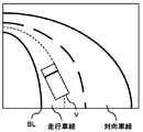
- FIG. 1A1 is a diagram for explaining the outline of the steering control device according to the present embodiment, and shows a state in which the vehicle is traveling along a curve in the vicinity of the center position of the traveling lane.
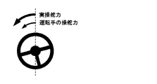
- FIG. 1A2 is a diagram for explaining the outline of the steering control device according to the present embodiment, and shows the relationship between the steering force and the actual steering force of the driver in the traveling state of FIG. 1A1.
- FIG. 1B1 is a diagram for explaining the outline of the steering control device according to the present embodiment, and shows a state in which the vehicle is traveling toward the inside of the curve slightly inside the traveling lane.
- FIG. 1A1 is a diagram for explaining the outline of the steering control device according to the present embodiment, and shows a state in which the vehicle is traveling toward the inside of the curve slightly inside the traveling lane.
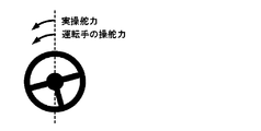
- FIG. 1B2 is a view for explaining the outline of the steering control device according to the present embodiment, and shows the relationship between the steering force and the actual steering force of the driver in the traveling state of FIG. 1B1.
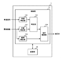
- FIG. 2 is a diagram illustrating a configuration of the steering control device.
- FIG. 3 is a flowchart of a typical operation of the steering control device.
- FIG. 1 is a diagram for explaining the outline of the steering control device according to the present embodiment.
- FIG. 1 shows a state in which the vehicle V is traveling in a traveling lane on a left-turned curve as viewed from above.
- FIG. 1A1 shows a state in which the vehicle V is traveling along a curve near the center position of the travel lane.
- the steering control device generates an assisting force in the same direction as the direction in which the driver steers in order to assist the steering operation by the driver.
- the steering control device generates an assist force (hereinafter referred to as power assist force) obtained by amplifying the driver's steering force by controlling the oil flow rate and the oil flow path based on the steering amount. .
- the actual steering force becomes larger than the steering force applied to the steering wheel by the driver.
- the driver can operate the steering wheel with a relatively light force.
- FIG. 1B1 shows a state where the vehicle V is traveling toward the inside of the curve, slightly inside the traveling lane. If the vehicle V continues to run in this state, it may deviate to the left from the lane marking BL on the inside of the curve. In such a state, if a power assist force for assisting the driver's steering wheel operation is applied, it is dangerous because the driver can easily operate the vehicle further toward the inside of the curve. On the other hand, if the assist force for forcibly moving the steering wheel in the direction to return the vehicle V to the center of the lane is generated by the motor, the vehicle V becomes unstable and the driver feels uneasy. .
- the steering control device determines that the vehicle V may deviate from the lane on the inner periphery side of the curve
- the driver controls the inner periphery side of the curve by reducing the hydraulic pressure that generates the power assist force. Making it difficult to steer towards By doing so, as shown in FIG. 1B2, the actual steering force becomes smaller than the actual steering force shown in FIG. 1A2, and the direction of the wheels autonomously changes in the direction in which the vehicle V advances in the straight traveling direction.
- the vehicle V starts to return to the center side of the lane by the self-aligning torque that is the force to be generated.
- the steering control device can reduce the probability that the vehicle V will deviate inside the curve while preventing the vehicle V from becoming unstable.
- the steering control device When the vehicle V is about to deviate from the lane outside the curve, the steering control device generates an assisting force for forcibly moving the steering wheel in a direction to return the vehicle V to the center side of the lane.
- the configuration and operation of the steering control device will be described in detail.
- FIG. 2 is a diagram illustrating a configuration of the steering control device 1.
- the steering control device 1 includes a control unit 11 and a storage unit 12.
- the control unit 11 is, for example, a CPU (Central Processing Unit).
- the storage unit 12 includes a storage medium such as a ROM (Read Only Memory), a RAM (Random Access Memory), and a hard disk.
- the storage unit 12 stores a program executed by the control unit 11.
- the control unit 11 functions as a vehicle speed identification unit 110, a position identification unit 111, a determination unit 112, a curvature identification unit 113, and a hydraulic pressure control unit 114 by executing a program stored in the storage unit 12.
- the vehicle speed specifying unit 110 specifies the traveling speed of the vehicle (hereinafter referred to as the vehicle speed) based on the vehicle speed signal output from the sensor that detects the rotational speed of the wheel.
- the vehicle speed identification unit 110 notifies the hydraulic control unit 114 of the identified vehicle speed.
- the position specifying unit 111 specifies the position of the vehicle V in the lane.
- the position specifying unit 111 specifies the position of the vehicle V in the left-right direction of the lane based on, for example, a captured image generated by a camera mounted on the vehicle V shooting the front of the vehicle V.
- the position specifying unit 111 notifies the determination unit 112 of information indicating the specified position.
- the determination unit 112 determines whether or not the vehicle V may deviate from the lane on the inner periphery side of the curve based on the captured image in front of the vehicle V. For example, when the determination unit 112 determines that the position of the vehicle V is within a predetermined range from the lane line based on the information indicating the position of the vehicle V notified from the position specifying unit 111, the determination unit 112 deviates from the lane. It is determined that there is a possibility of
- the determination unit 112 may determine whether or not there is a possibility of deviating from the lane based on the change state of the position of the vehicle V. For example, the determination unit 112 may deviate from the lane when the position of the vehicle V specified based on the captured images generated at a plurality of different timings is moving toward the lane line. judge.
- the determination unit 112 may determine a condition for determining that the vehicle V may deviate from the lane based on the vehicle speed specified by the vehicle speed specifying unit 110. For example, the determination unit 112 determines that the higher the vehicle speed is, the more likely the vehicle V is to deviate from the lane when the position of the vehicle V is greater from the lane marking line BL inside the lane curve. It may be determined that the smaller the vehicle speed, the more likely that the vehicle V will depart from the lane after the position of the vehicle V approaches the lane marking line BL inside the lane curve.
- the curvature specifying unit 113 specifies the curvature of the curve ahead of the vehicle V based on the captured image. For example, the curvature specifying unit 113 calculates the curvature of each lane marking on both sides of the vehicle V in the captured image, and sets the average value of the calculated curvatures as the curvature of the curve. The curvature specifying unit 113 notifies the hydraulic control unit 114 of the specified curvature.
- the hydraulic control unit 114 is a power steering that generates an assisting force for assisting steering of the steering wheel of the vehicle V when the determination unit 112 determines that the vehicle V may deviate from the lane on the inner periphery side of the curve.
- the hydraulic pressure is controlled to decrease by reducing the discharge flow rate of the hydraulic pump. By doing so, the force required for the driver to steer toward the inner periphery of the curve increases, and the steering wheel becomes heavy. As a result, the vehicle V is prevented from moving toward the inner periphery of the curve, and the vehicle V can be made difficult to depart from the lane.
- the hydraulic pressure control unit 114 reduces the hydraulic pressure for generating an auxiliary force when the vehicle V operates the handle in the direction toward the inner peripheral side of the curve, and handles the handle in the direction away from the inner peripheral side of the curve.
- the hydraulic pressure for generating the assisting force when operating the may not be reduced. By doing so, the driver can easily operate the steering wheel in a direction away from the inner peripheral side of the curve, and the vehicle V can easily return to the center position of the lane.
- the hydraulic control unit 114 may perform control so that the hydraulic pressure is gradually reduced based on the position of the vehicle V specified by the position specifying unit 111. Specifically, the oil pressure control unit 114 generates the oil pressure in the initial state while the vehicle V is traveling at a position away from the lane marking BL on the inner circumference side of the curve by a predetermined distance, and the vehicle V Is within a predetermined distance from the lane marking BL on the inner circumference side of the curve, the hydraulic pressure is gradually reduced. Then, the hydraulic pressure control unit 114 decreases the hydraulic pressure as the vehicle V approaches the lane marking line BL. By doing so, the handle becomes heavier as the vehicle V approaches the lane marking line BL, so that the driver is prevented from operating the handle toward the inside of the curve.
- the hydraulic control unit 114 may control the hydraulic pressure based on the vehicle speed at which the determination unit 112 determines that the vehicle V may deviate from the lane. For example, the hydraulic pressure control unit 114 increases the amount by which the hydraulic pressure is decreased as the speed of the vehicle V increases when the position of the vehicle V reaches a predetermined distance from the lane marking BL, and the speed of the vehicle V can be decreased. The smaller the value, the smaller the amount to lower the hydraulic pressure. By doing so, the self-aligning torque can be increased when the departure speed of the vehicle V is large and it is necessary to quickly return the position of the vehicle V to the center side of the lane.
- the hydraulic control unit 114 may control the hydraulic pressure based on the direction of the vehicle V specified by the position specifying unit 111. For example, when the vehicle V is traveling in a direction approaching the lane marking BL on the inner periphery side of the curve, the hydraulic control unit 114 assists the vehicle V in operating the handle in a direction approaching the lane marking BL. Reduce the hydraulic pressure that generates force. In addition, when traveling in a direction away from the lane line BL, the hydraulic control unit 114 increases the hydraulic pressure that generates an assisting force for operating the steering wheel in a direction in which the vehicle V approaches the lane line BL. In this way, even when the vehicle V is near the lane line BL, if the probability of deviating from the lane is low, it is possible to generate a sufficiently large assist force. It can prevent that property falls.
- the hydraulic control unit 114 may perform control so as to decrease the hydraulic pressure on condition that the curvature of the curve specified by the curvature specifying unit 113 is larger than a predetermined value. In this way, the vehicle V can travel more stably than the case where the assist force by the motor in a sharp curve is used, and the driver's operability is improved by the power assist force in a gentle curve. Can be maintained.
- FIG. 3 is a flowchart of a typical operation of the steering control device 1.
- the position specifying unit 111 specifies the position of the vehicle V in the lane (S11).
- the determination unit 112 determines whether or not the vehicle V may deviate from the lane based on the identified vehicle speed and the position of the vehicle V (S12).
- the hydraulic control unit 114 determines whether the curvature of the road ahead of the vehicle V is greater than a predetermined threshold (S13). ). If the determination unit 112 determines that the road curvature is greater than the predetermined threshold (YES in S13), the hydraulic control unit 114 reduces the hydraulic pressure so that the driver does not turn the steering wheel too far inside the curve. The power assist force is reduced (S14).
- the determination unit 112 monitors whether or not the probability that the vehicle V departs from the lane has decreased (S15).
- hydraulic control unit 114 restores the power assist force by returning the hydraulic pressure to the standard value (S16).
- the steering control device 1 repeats the processing from step S11 to S16 until the engine stops.
- the determination unit 112 determines whether or not the vehicle V deviates from the lane based on the position of the vehicle V in the lane, but determines whether or not the vehicle V deviates from the lane.
- the method is not limited to this.
- the determination unit 112 may determine whether or not there is a possibility of departure based on the curvature of the curve specified by the curvature specifying unit 113 based on the captured image and the steering angle of the steering wheel. For example, when the steering angle is too large with respect to the curvature of the curve, the determination unit 112 can also determine that the vehicle V may deviate from the lane.
- the steering control device 1 reduces the hydraulic pressure that generates the power assist force that assists the steering of the steering wheel when it is determined that the vehicle V may deviate from the lane on the inner periphery side of the curve. . By doing so, the vehicle V returns to the center side of the lane by self-aligning torque, so that the vehicle V is more stable even in a sharp curve than when the direction of the vehicle V is forcibly changed by the motor. It becomes possible to keep running.
- the present invention has an effect that it is possible to ensure the running stability of the vehicle while preventing lane departure on the inner periphery side of the curve, and is useful for a steering control device, a steering control method, and the like.
Landscapes
- Engineering & Computer Science (AREA)
- Chemical & Material Sciences (AREA)
- Combustion & Propulsion (AREA)
- Transportation (AREA)
- Mechanical Engineering (AREA)
- Steering Control In Accordance With Driving Conditions (AREA)
Abstract
操舵制御装置1は、車両Vの前方を撮影して生成された撮像画像に基づいて、車両Vがカーブの内周側で車線を逸脱する可能性があるか否かを判定する判定部112と、判定部112が、車両Vがカーブの内周側で車線を逸脱する可能性があると判定した場合に、車両Vのハンドルの操舵を補助する補助力を発生させる油圧を下げるように制御する油圧制御部114と、を有する。
Description
本開示は、車両の操舵を制御するための操舵制御装置及び操舵制御方法に関する。
車両が車線を逸脱することを防ぐために、車両を車線内に維持する向きの補助力を発生させる方法が知られている。特許文献1には、道路のカーブの形状に応じて目標ハンドル角を演算し、ハンドルの操舵角が目標ハンドル角になるように、電動モーターを用いて補助力を発生する技術が開示されている。
車両が車線を逸脱することを防ぐために電動モーターを用いて補助力(操舵反力ともいう)を発生する場合、運転者がハンドルを操舵する向きと反対の向きに補助力を発生させる必要がある。この補助力は、運転者の意図する向きと反対の向きに車両を向けようとする力なので、急なカーブで補助力が発生すると、運転操作が不安定になるという問題が生じていた。例えば、運転者がハンドルを戻し終わった後に、運転者のハンドル操作と逆向きの補助力が加わることにより、運転者が、必要以上にハンドルを操作してしまうという問題が生じていた。
そこで、本開示はこれらの点に鑑みてなされたものであり、カーブの内周側での車線の逸脱を防止しつつ、車両の走行の安定性を確保するための操舵制御装置及び操舵制御方法を提供することを目的とする。
本開示の第1の態様の操舵制御装置は、車両の前方を撮影して生成された撮像画像に基づいて、前記車両がカーブの内周側で車線を逸脱する可能性があるか否かを判定する判定部と、前記判定部が、前記車両がカーブの内周側で車線を逸脱する可能性があると判定した場合に、前記車両のハンドルの操舵を補助する補助力を発生させる油圧を下げるように制御する油圧制御部と、を有する。
前記撮像画像に基づいて、車線における前記車両の位置を特定する位置特定部をさらに有し、前記油圧制御部は、前記位置特定部が特定した前記車両の位置に基づいて、段階的に前記油圧を下げるように制御してもよい。
前記位置特定部は、前記車両の向きをさらに特定し、前記油圧制御部は、前記位置特定部が特定した前記車両の向きに基づいて、前記油圧の大きさを制御してもよい。
前記撮像画像に基づいて、前記車両の前方のカーブの曲率を特定する曲率特定部をさらに有し、前記油圧制御部は、前記曲率特定部が特定した前記カーブの曲率が所定の値よりも大きいことを条件として、前記油圧を下げるように制御してもよい。
前記車両の走行速度を特定する車速特定部をさらに有し、前記油圧制御部は、前記車両が車線を逸脱する可能性があると判定した時点での前記車両の走行速度に基づいて、前記油圧の大きさを制御してもよい。
前記車両の走行速度を特定する車速特定部と、前記撮像画像に基づいて、前記車線における前記車両の位置を特定する位置特定部と、前記撮像画像に基づいて、前記車両の前方のカーブの曲率を特定する曲率特定部と、をさらに有し、前記判定部は、前記車速特定部により特定された前記車両の走行速度と前記位置特定部により特定された前記車両の位置との少なくとも一方に基づいて、前記車両が前記カーブの内周側で前記車線を逸脱する可能性があるか否かを判定し、前記判定部が、前記車両が前記カーブの内周側で車線を逸脱する可能性があると判定した場合に、前記油圧制御部は、前記曲率特定部が特定した前記カーブの曲率が所定の値よりも大きいか否かを判定し、前記油圧制御部は、前記曲率特定部が特定した前記カーブの曲率が前記所定の値よりも大きいと判定した場合に、前記油圧を下げるように制御し、前記油圧制御部が前記油圧を下げるように制御した後、前記判定部は、前記車両が前記車線を逸脱する確率が低下したか否かを判定し、前記判定部が、前記車両が前記車線を逸脱する確率が低下したと判定した場合に、前記油圧制御部は、前記油圧を標準値に戻すように制御してもよい。
本開示の第2の態様の操舵制御方法は、コンピュータを備えた車両の操舵制御方法であって、前記方法は前記コンピュータに、車両の前方を撮影して生成された撮像画像に基づいて、前記車両がカーブの内周側で車線を逸脱する可能性があるか否かを判定するステップと、前記車両がカーブの内周側で車線を逸脱する可能性があると判定した場合に、前記車両のハンドルの操舵を補助する補助力を発生させる油圧を下げるステップと、を実行させる。
本開示によれば、カーブの内周側での車線の逸脱を防止しつつ、車両の走行の安定性を確保することができるという効果を奏する。
[操舵制御装置の概要]
図1は、本実施形態に係る操舵制御装置の概要を説明するための図である。図1は、車両Vが、左曲がりのカーブにおいて走行車線を走行している様子を上から見た状態を示している。
図1は、本実施形態に係る操舵制御装置の概要を説明するための図である。図1は、車両Vが、左曲がりのカーブにおいて走行車線を走行している様子を上から見た状態を示している。
図1A1は、車両Vが走行車線の中央位置の付近をカーブに沿って走行している状態を示している。このような場合、操舵制御装置は、運転手によるハンドル操作を補助するために、運転手が操舵する向きと同じ向きの補助力を発生させる。具体的には、操舵制御装置は、操舵量に基づいてオイルの流量及びオイルの流路を制御することにより、運転手の操舵力を増幅した補助力(以下、パワーアシスト力という)を発生させる。
このようにすることで、図1A2に示すように、実際の操舵力は、運転手がハンドルに加えた操舵力よりも大きくなる。その結果、車両Vが重量の大きい商用車であっても、運転手は比較的軽い力でハンドルを操作することができる。
図1B1は、車両Vが走行車線のやや内側において、カーブの内側に向かって走行している状態を示している。車両Vがこのままの状態で走り続けると、カーブの内側の車線区画線BLよりも左側に逸脱してしまう可能性がある。このような状態において、運転手のハンドル操作を補助するパワーアシスト力が加えられると、運転手がさらにカーブの内側に向かうように操作をしやすくなるので危険である。一方で、車両Vを車線の中央側に戻す向きに強制的にハンドルを動かすための補助力をモーターにより発生させると、車両Vが不安定な状態になり、運転手が不安感を抱いてしまう。
そこで、操舵制御装置は、車両Vがカーブの内周側で車線を逸脱する可能性があると判定した場合に、パワーアシスト力を発生させる油圧を下げることで、運転手がカーブの内周側に向かうように操舵することを困難にする。このようにすることで、図1B2に示すように、実際の操舵力が図1A2に示した実際の操舵力よりも小さくなり、車両Vが直進方向に進む向きに自律的に車輪の向きを変化させる力であるセルフアライニングトルクにより、車両Vが車線の中央側に戻り始める。その結果、操舵制御装置は、車両Vが不安定な状態になることを防止しつつ、車両Vがカーブの内側に逸脱する蓋然性を低下させることができる。
なお、操舵制御装置は、車両Vがカーブの外側で車線を逸脱しそうになる場合は、車両Vを車線の中央側に戻す向きに強制的にハンドルを動かすための補助力をモーターにより発生させる。
以下、操舵制御装置の構成及び動作を詳細に説明する。
以下、操舵制御装置の構成及び動作を詳細に説明する。
[操舵制御装置1の構成]
図2は、操舵制御装置1の構成を示す図である。操舵制御装置1は、制御部11及び記憶部12を有する。制御部11は、例えばCPU(Central Processing Unit)である。記憶部12は、ROM(Read Only Memory)、RAM(Random Access Memory)及びハードディスク等の記憶媒体を有する。記憶部12は、制御部11が実行するプログラムを記憶している。
図2は、操舵制御装置1の構成を示す図である。操舵制御装置1は、制御部11及び記憶部12を有する。制御部11は、例えばCPU(Central Processing Unit)である。記憶部12は、ROM(Read Only Memory)、RAM(Random Access Memory)及びハードディスク等の記憶媒体を有する。記憶部12は、制御部11が実行するプログラムを記憶している。
制御部11は、記憶部12に記憶されたプログラムを実行することにより、車速特定部110、位置特定部111、判定部112、曲率特定部113及び油圧制御部114として機能する。
車速特定部110は、車輪の回転速度を検出するセンサーが出力する車速信号に基づいて、車両の走行速度(以下、車速という)を特定する。車速特定部110は、特定した車速を油圧制御部114に通知する。
位置特定部111は、車線における車両Vの位置を特定する。位置特定部111は、例えば車両Vに搭載されたカメラが車両Vの前方を撮影することにより生成された撮像画像に基づいて、車線の左右方向における車両Vの位置を特定する。位置特定部111は、特定した位置を示す情報を判定部112に通知する。
判定部112は、車両Vの前方の撮像画像に基づいて、車両Vがカーブの内周側で車線を逸脱する可能性があるか否かを判定する。例えば、判定部112は、位置特定部111から通知された車両Vの位置を示す情報に基づいて、車両Vの位置が車線区画線から所定の範囲内であると判定した場合に、車線を逸脱する可能性があると判定する。
判定部112は、車両Vの位置の変化状況に基づいて、車線を逸脱する可能性の有無を判定してもよい。例えば、判定部112は、複数の異なるタイミングで生成された撮像画像に基づいて特定された車両Vの位置が車線区画線に向けて移動している場合に、車線を逸脱する可能性があると判定する。
また、判定部112は、車速特定部110が特定した車速に基づいて、車両Vが車線を逸脱する可能性があると判定する条件を決定してもよい。例えば、判定部112は、車速が大きければ大きいほど、車両Vの位置が車線のカーブの内側の車線区画線BLからの距離が大きい時点で車両Vが車線を逸脱する可能性があると判定し、車速が小さければ小さいほど、車両Vの位置が車線のカーブの内側の車線区画線BLに近づいた時点になってから、車両Vが車線を逸脱する可能性があると判定してもよい。
曲率特定部113は、撮像画像に基づいて、車両Vの前方のカーブの曲率を特定する。曲率特定部113は、例えば、撮像画像における車両Vの両側の車線区画線それぞれの曲率を算出し、算出したそれぞれの曲率の平均値を、カーブの曲率とする。曲率特定部113は、特定した曲率を油圧制御部114に通知する。
油圧制御部114は、判定部112が、車両Vがカーブの内周側で車線を逸脱する可能性があると判定した場合に、車両Vのハンドルの操舵を補助する補助力を発生させるパワーステアリング用の油圧ポンプの吐出流量を小さくすることにより、油圧を下げるように制御する。このようにすることで、運転手がカーブの内周側に操舵をするために必要な力が大きくなり、ハンドルが重くなる。その結果、車両Vがカーブの内周側に向かうことが抑制され、車両Vが車線を逸脱しにくくすることができる。
この際、油圧制御部114は、車両Vがカーブの内周側に向かう向きにハンドルを操作する際の補助力を発生するための油圧を小さくするとともに、カーブの内周側から離れる向きにハンドルを操作する際の補助力を発生するための油圧を小さくしないようにしてもよい。このようにすることで、運転手は、カーブの内周側から離れる向きにハンドルを操作しやすくなるので、車両Vが車線の中央位置に戻りやすくなる。
油圧制御部114は、位置特定部111が特定した車両Vの位置に基づいて、段階的に油圧を下げるように制御してもよい。具体的には、油圧制御部114は、車両Vがカーブの内周側の車線区画線BLから所定の距離より離れた位置を走行している間は、初期状態の油圧を発生させ、車両Vがカーブの内周側の車線区画線BLから所定の距離以内になると、油圧を徐々に低下させる。そして、油圧制御部114は、車両Vが車線区画線BLに近づくにつれて油圧を小さくする。このようにすることで、車両Vが車線区画線BLに近づくにつれてハンドルが重くなるので、運転手がカーブの内側に向けてハンドルを操作することが防止される。
油圧制御部114は、車両Vが車線を逸脱する可能性があると判定部112が判定した時点での車速に基づいて、油圧の大きさを制御してもよい。例えば、油圧制御部114は、車両Vの位置が車線区画線BLから所定の距離になった時点での車両Vの速度が大きければ大きいほど油圧を下げる量を大きくし、車両Vの速度が小さければ小さいほど油圧を下げる量を小さくする。このようにすることで、車両Vの逸脱速度が大きく、車両Vの位置を早急に車線の中央側に戻す必要がある場合に、セルフアライニングトルクを大きくすることができる。
また、油圧制御部114は、位置特定部111が特定した車両Vの向きに基づいて、油圧の大きさを制御してもよい。例えば、油圧制御部114は、車両Vがカーブの内周側の車線区画線BLに近づく向きに走行している場合に、車両Vが車線区画線BLに近づく向きにハンドルを操作するための補助力を発生させる油圧を下げる。また、油圧制御部114は、車線区画線BLから離れる向きに走行している場合に、車両Vが車線区画線BLに近づく向きにハンドルを操作するための補助力を発生させる油圧を上げる。このようにすることで、車両Vが車線区画線BLの近くにいても、車線を逸脱する確率が低い場合には十分な大きさの補助力を発生することができるので、運転手のハンドル操作性が低下することを防止できる。
なお、セルフアライニングトルクにより車両Vを直進方向に戻す制御は、道路の曲率が大きい急なカーブで特に有効である。そこで、油圧制御部114は、曲率特定部113が特定したカーブの曲率が所定の値よりも大きいことを条件として、油圧を下げるように制御してもよい。このようにすることで、車両Vは、急なカーブにおけるモーターによる補助力を用いる場合に比べて安定した走行が可能になるとともに、緩やかなカーブにおいては、パワーアシスト力により運転手の操作性を維持することができる。
[操舵制御装置1の動作フローチャート]
図3は、操舵制御装置1の典型的な動作のフローチャートである。
まず、位置特定部111は、車線における車両Vの位置を特定する(S11)。続いて、判定部112は、特定した車速及び車両Vの位置に基づいて、車両Vが車線を逸脱する可能性の有無を判定する(S12)。
図3は、操舵制御装置1の典型的な動作のフローチャートである。
まず、位置特定部111は、車線における車両Vの位置を特定する(S11)。続いて、判定部112は、特定した車速及び車両Vの位置に基づいて、車両Vが車線を逸脱する可能性の有無を判定する(S12)。
判定部112が、車両Vが車線を逸脱する可能性があると判定した場合、油圧制御部114は、車両Vの前方の道路の曲率が所定の閾値よりも大きいか否かを判定する(S13)。判定部112が、道路の曲率が所定の閾値よりも大きいと判定した場合(S13においてYES)、油圧制御部114は油圧を下げることにより、運転手がカーブの内側にハンドルを切り過ぎないようにパワーアシスト力を低下させる(S14)。
その後、判定部112が、車両Vが車線を逸脱する確率が低下したかどうかを監視する(S15)。判定部112が、車両Vが車線を逸脱する確率が低下したと判定した場合(S15においてYES)、油圧制御部114は、油圧を標準値に戻すことでパワーアシスト力を回復させる(S16)。操舵制御装置1は、エンジンが停止するまでの間、ステップS11からS16までの処理を繰り返す。
(変形例)
上記の説明において、判定部112は、車線における車両Vの位置に基づいて、車両Vが車線を逸脱する可能性の有無を判定したが、車両Vが車線を逸脱する可能性の有無を判定する方法は、これに限らない。判定部112は、撮像画像に基づいて曲率特定部113が特定したカーブの曲率と、ハンドルの操舵角とに基づいて、逸脱の可能性の有無を判定してもよい。判定部112は、例えば、カーブの曲率に対して操舵角が大き過ぎる場合に、車両Vが車線を逸脱する可能性があると判定することもできる。
上記の説明において、判定部112は、車線における車両Vの位置に基づいて、車両Vが車線を逸脱する可能性の有無を判定したが、車両Vが車線を逸脱する可能性の有無を判定する方法は、これに限らない。判定部112は、撮像画像に基づいて曲率特定部113が特定したカーブの曲率と、ハンドルの操舵角とに基づいて、逸脱の可能性の有無を判定してもよい。判定部112は、例えば、カーブの曲率に対して操舵角が大き過ぎる場合に、車両Vが車線を逸脱する可能性があると判定することもできる。
[操舵制御装置1による効果]
以上説明したように、操舵制御装置1は、車両Vがカーブの内周側で車線を逸脱する可能性があると判定した場合に、ハンドルの操舵を補助するパワーアシスト力を発生させる油圧を下げる。このようにすることで、車両Vが、セルフアライニングトルクによって車線の中央側に戻るので、モーターにより強制的に車両Vの向きを変える場合に比べて、急なカーブにおいても車両Vの安定した走行を維持することが可能になる。
以上説明したように、操舵制御装置1は、車両Vがカーブの内周側で車線を逸脱する可能性があると判定した場合に、ハンドルの操舵を補助するパワーアシスト力を発生させる油圧を下げる。このようにすることで、車両Vが、セルフアライニングトルクによって車線の中央側に戻るので、モーターにより強制的に車両Vの向きを変える場合に比べて、急なカーブにおいても車両Vの安定した走行を維持することが可能になる。
以上、本開示を実施の形態を用いて説明したが、本開示の技術的範囲は上記実施の形態に記載の範囲には限定されない。上記実施の形態に、多様な変更又は改良を加えることが可能であることが当業者に明らかである。そのような変更又は改良を加えた形態も本開示の技術的範囲に含まれ得ることが、特許請求の範囲の記載から明らかである。
本出願は、2016年8月25日付で出願された日本国特許出願(特願2016-164491)に基づくものであり、その内容はここに参照として取り込まれる。
本出願は、2016年8月25日付で出願された日本国特許出願(特願2016-164491)に基づくものであり、その内容はここに参照として取り込まれる。
本発明は、カーブの内周側での車線の逸脱を防止しつつ、車両の走行の安定性を確保することができるという効果を有し、操舵制御装置及び操舵制御方法等に有用である。
1 操舵制御装置
11 制御部
110 車速特定部
111 位置特定部
112 判定部
113 曲率特定部
114 油圧制御部
11 制御部
110 車速特定部
111 位置特定部
112 判定部
113 曲率特定部
114 油圧制御部
Claims (12)
- 車両の前方を撮影して生成された撮像画像に基づいて、前記車両がカーブの内周側で車線を逸脱する可能性があるか否かを判定する判定部と、
前記判定部が、前記車両がカーブの内周側で車線を逸脱する可能性があると判定した場合に、前記車両のハンドルの操舵を補助する補助力を発生させる油圧を下げるように制御する油圧制御部と、
を有する操舵制御装置。 - 前記撮像画像に基づいて、車線における前記車両の位置を特定する位置特定部をさらに有し、
前記油圧制御部は、前記位置特定部が特定した前記車両の位置に基づいて、段階的に前記油圧を下げるように制御する、
請求項1に記載の操舵制御装置。 - 前記位置特定部は、前記車両の向きをさらに特定し、
前記油圧制御部は、前記位置特定部が特定した前記車両の向きに基づいて、前記油圧の大きさを制御する、
請求項2に記載の操舵制御装置。 - 前記撮像画像に基づいて、前記車両の前方のカーブの曲率を特定する曲率特定部をさらに有し、
前記油圧制御部は、前記曲率特定部が特定した前記カーブの曲率が所定の値よりも大きいことを条件として、前記油圧を下げるように制御する、
請求項1から3のいずれか一項に記載の操舵制御装置。 - 前記車両の走行速度を特定する車速特定部をさらに有し、
前記油圧制御部は、前記車両が車線を逸脱する可能性があると判定した時点での前記車両の走行速度に基づいて、前記油圧の大きさを制御する、
請求項1から4のいずれか一項に記載の操舵制御装置。 - 前記車両の走行速度を特定する車速特定部と、
前記撮像画像に基づいて、前記車線における前記車両の位置を特定する位置特定部と、
前記撮像画像に基づいて、前記車両の前方のカーブの曲率を特定する曲率特定部と、をさらに有し、
前記判定部は、前記車速特定部により特定された前記車両の走行速度と前記位置特定部により特定された前記車両の位置との少なくとも一方に基づいて、前記車両が前記カーブの内周側で前記車線を逸脱する可能性があるか否かを判定し、
前記判定部が、前記車両が前記カーブの内周側で車線を逸脱する可能性があると判定した場合に、前記油圧制御部は、前記曲率特定部が特定した前記カーブの曲率が所定の値よりも大きいか否かを判定し、
前記油圧制御部は、前記曲率特定部が特定した前記カーブの曲率が前記所定の値よりも大きいと判定した場合に、前記油圧を下げるように制御し、
前記油圧制御部が前記油圧を下げるように制御した後、前記判定部は、前記車両が前記車線を逸脱する確率が低下したか否かを判定し、
前記判定部が、前記車両が前記車線を逸脱する確率が低下したと判定した場合に、前記油圧制御部は、前記油圧を標準値に戻すように制御する、
請求項1に記載の操舵制御装置。 - コンピュータを備えた車両の操舵制御方法であって、前記方法は前記コンピュータに以下を実行させる:
車両の前方を撮影して生成された撮像画像に基づいて、前記車両がカーブの内周側で車線を逸脱する可能性があるか否かを判定するステップと、
前記車両がカーブの内周側で車線を逸脱する可能性があると判定した場合に、前記車両のハンドルの操舵を補助する補助力を発生させる油圧を下げるステップ。 - 請求項7に記載の操舵制御方法であって、
前記方法は前記コンピュータにさらに以下を実行させる:
前記撮像画像に基づいて、車線における前記車両の位置を特定するステップ、
前記油圧を下げるステップにおいて、前記方法は前記コンピュータに、前記特定した前記車両の位置に基づいて、段階的に前記油圧を下げるように制御する。 - 請求項8に記載の操舵制御方法であって、
前記車両の位置を特定するステップにおいて、前記方法は前記コンピュータに、前記車両の向きをさらに特定させ、
前記油圧を下げるステップにおいて、前記方法は前記コンピュータに、前記特定した前記車両の向きに基づいて、前記油圧の大きさを制御する。 - 請求項7から9のいずれか一項に記載の操舵制御方法であって、
前記方法は前記コンピュータにさらに以下を実行させる:
前記撮像画像に基づいて、前記車両の前方のカーブの曲率を特定するステップ、
前記油圧を下げるステップにおいて、前記方法は前記コンピュータに、前記特定した前記カーブの曲率が所定の値よりも大きいことを条件として、前記油圧を下げるように制御する。 - 請求項7から9のいずれか一項に記載の操舵制御方法であって、
前記方法は前記コンピュータにさらに以下を実行させる:
前記車両の走行速度を特定するステップ、
前記油圧を下げるステップにおいて、前記方法は前記コンピュータに、前記車両が車線を逸脱する可能性があると判定した時点での前記車両の走行速度に基づいて、前記油圧の大きさを制御する。 - 請求項7に記載の操舵制御方法であって、
前記方法は前記コンピュータにさらに以下を実行させる:
前記車両の走行速度を特定するステップと、
前記撮像画像に基づいて、前記車線における前記車両の位置を特定するステップと、
前記撮像画像に基づいて、前記車両の前方のカーブの曲率を特定するステップ、
前記方法は前記コンピュータに:
前記判定ステップにおいて、前記特定された前記車両の走行速度と前記特定された前記車両の位置との少なくとも一方に基づいて、前記車両が前記カーブの内周側で前記車線を逸脱する可能性があるか否かを判定させ、
前記車両が前記カーブの内周側で車線を逸脱する可能性があると判定された場合に、前記特定した前記カーブの曲率が所定の値よりも大きいか否かを判定させ、
前記特定した前記カーブの曲率が前記所定の値よりも大きいと判定された場合に、前記油圧を下げるように制御し、
前記油圧を下げる制御が行われた後、前記車両が前記車線を逸脱する確率が低下したか否かを判定させ、
前記車両が前記車線を逸脱する確率が低下したと判定した場合に、前記油圧を標準値に戻すように制御する。
Applications Claiming Priority (2)
| Application Number | Priority Date | Filing Date | Title |
|---|---|---|---|
| JP2016-164491 | 2016-08-25 | ||
| JP2016164491A JP2018030472A (ja) | 2016-08-25 | 2016-08-25 | 操舵制御装置及び操舵制御方法 |
Publications (1)
| Publication Number | Publication Date |
|---|---|
| WO2018038147A1 true WO2018038147A1 (ja) | 2018-03-01 |
Family
ID=61246168
Family Applications (1)
| Application Number | Title | Priority Date | Filing Date |
|---|---|---|---|
| PCT/JP2017/030078 Ceased WO2018038147A1 (ja) | 2016-08-25 | 2017-08-23 | 操舵制御装置及び操舵制御方法 |
Country Status (2)
| Country | Link |
|---|---|
| JP (1) | JP2018030472A (ja) |
| WO (1) | WO2018038147A1 (ja) |
Cited By (1)
| Publication number | Priority date | Publication date | Assignee | Title |
|---|---|---|---|---|
| JP2023065143A (ja) * | 2021-10-27 | 2023-05-12 | トヨタ自動車株式会社 | 車両運転支援装置 |
Families Citing this family (1)
| Publication number | Priority date | Publication date | Assignee | Title |
|---|---|---|---|---|
| KR102032501B1 (ko) * | 2019-06-10 | 2019-10-15 | 오토아이티(주) | 차선 이탈 감지 방법 및 장치 |
Citations (3)
| Publication number | Priority date | Publication date | Assignee | Title |
|---|---|---|---|---|
| JP2003154954A (ja) * | 2001-11-20 | 2003-05-27 | Hitachi Unisia Automotive Ltd | パワーステアリング装置 |
| JP2004034792A (ja) * | 2002-07-02 | 2004-02-05 | Nissan Motor Co Ltd | 車線逸脱防止方法、及び車線逸脱防止装置 |
| JP2009255878A (ja) * | 2008-04-21 | 2009-11-05 | Jtekt Corp | 操舵装置 |
-
2016
- 2016-08-25 JP JP2016164491A patent/JP2018030472A/ja active Pending
-
2017
- 2017-08-23 WO PCT/JP2017/030078 patent/WO2018038147A1/ja not_active Ceased
Patent Citations (3)
| Publication number | Priority date | Publication date | Assignee | Title |
|---|---|---|---|---|
| JP2003154954A (ja) * | 2001-11-20 | 2003-05-27 | Hitachi Unisia Automotive Ltd | パワーステアリング装置 |
| JP2004034792A (ja) * | 2002-07-02 | 2004-02-05 | Nissan Motor Co Ltd | 車線逸脱防止方法、及び車線逸脱防止装置 |
| JP2009255878A (ja) * | 2008-04-21 | 2009-11-05 | Jtekt Corp | 操舵装置 |
Cited By (3)
| Publication number | Priority date | Publication date | Assignee | Title |
|---|---|---|---|---|
| JP2023065143A (ja) * | 2021-10-27 | 2023-05-12 | トヨタ自動車株式会社 | 車両運転支援装置 |
| JP7639654B2 (ja) | 2021-10-27 | 2025-03-05 | トヨタ自動車株式会社 | 車両運転支援装置 |
| US12258012B2 (en) | 2021-10-27 | 2025-03-25 | Toyota Jidosha Kabushiki Kaisha | Vehicle driving support device |
Also Published As
| Publication number | Publication date |
|---|---|
| JP2018030472A (ja) | 2018-03-01 |
Similar Documents
| Publication | Publication Date | Title |
|---|---|---|
| JP5255988B2 (ja) | 操舵支援装置 | |
| JP5813196B1 (ja) | 電動パワーステアリング装置 | |
| US8521416B2 (en) | Vehicle control apparatus and vehicle control method | |
| CN106494497B (zh) | 车辆的操舵反力控制装置 | |
| JP6690506B2 (ja) | 車両の車線内走行支援装置 | |
| CN108238099B (zh) | 车辆行驶控制装置及自主驾驶控制方法 | |
| US11560174B2 (en) | Automatic steering control device | |
| KR102075329B1 (ko) | 차량 제어 방법 및 차량 제어 장치 | |
| JP2015003566A (ja) | 逸脱防止装置 | |
| JP6753199B2 (ja) | 車線維持支援装置及び車線維持支援方法 | |
| US20200238963A1 (en) | Deflection control apparatus | |
| CN111712410B (zh) | 驾驶辅助装置、驾驶辅助方法及驾驶辅助系统 | |
| CN109562783B (zh) | 转向辅助装置及转向辅助方法 | |
| WO2018025791A1 (ja) | 補助力制御装置及び補助力制御方法 | |
| JP5328738B2 (ja) | 後側方操舵支援技術 | |
| WO2018038147A1 (ja) | 操舵制御装置及び操舵制御方法 | |
| JP2019156323A (ja) | 車両走行制御装置、車両走行制御方法、及び車両走行制御システム | |
| JP2010158987A (ja) | 車両用転舵制御装置 | |
| JP4923567B2 (ja) | 操舵装置 | |
| JP6711198B2 (ja) | 車線維持支援装置及び車線維持支援方法 | |
| JP2021142790A (ja) | 操舵制御装置 | |
| JP2017081250A (ja) | 車両の操舵反力制御装置 | |
| WO2018025788A1 (ja) | 補助力制御装置及び補助力制御方法 | |
| CN115675455A (zh) | 车道保持系统的控制方法和设备 | |
| WO2018056251A1 (ja) | 車線逸脱抑制装置及び車線逸脱抑制方法 |
Legal Events
| Date | Code | Title | Description |
|---|---|---|---|
| 121 | Ep: the epo has been informed by wipo that ep was designated in this application |
Ref document number: 17843625 Country of ref document: EP Kind code of ref document: A1 |
|
| NENP | Non-entry into the national phase |
Ref country code: DE |
|
| 122 | Ep: pct application non-entry in european phase |
Ref document number: 17843625 Country of ref document: EP Kind code of ref document: A1 |