WO2018037850A1 - 光学製品並びにプラスチック眼鏡レンズ及び眼鏡 - Google Patents
光学製品並びにプラスチック眼鏡レンズ及び眼鏡 Download PDFInfo
- Publication number
- WO2018037850A1 WO2018037850A1 PCT/JP2017/027848 JP2017027848W WO2018037850A1 WO 2018037850 A1 WO2018037850 A1 WO 2018037850A1 JP 2017027848 W JP2017027848 W JP 2017027848W WO 2018037850 A1 WO2018037850 A1 WO 2018037850A1
- Authority
- WO
- WIPO (PCT)
- Prior art keywords
- layer
- optical
- reflectance
- sio
- wavelength
- Prior art date
- Legal status (The legal status is an assumption and is not a legal conclusion. Google has not performed a legal analysis and makes no representation as to the accuracy of the status listed.)
- Ceased
Links
Images


Classifications
-
- G—PHYSICS
- G02—OPTICS
- G02C—SPECTACLES; SUNGLASSES OR GOGGLES INSOFAR AS THEY HAVE THE SAME FEATURES AS SPECTACLES; CONTACT LENSES
- G02C7/00—Optical parts
- G02C7/10—Filters, e.g. for facilitating adaptation of the eyes to the dark; Sunglasses
-
- G—PHYSICS
- G02—OPTICS
- G02B—OPTICAL ELEMENTS, SYSTEMS OR APPARATUS
- G02B1/00—Optical elements characterised by the material of which they are made; Optical coatings for optical elements
- G02B1/10—Optical coatings produced by application to, or surface treatment of, optical elements
- G02B1/11—Anti-reflection coatings
- G02B1/113—Anti-reflection coatings using inorganic layer materials only
- G02B1/115—Multilayers
-
- G—PHYSICS
- G02—OPTICS
- G02B—OPTICAL ELEMENTS, SYSTEMS OR APPARATUS
- G02B5/00—Optical elements other than lenses
- G02B5/08—Mirrors
-
- G—PHYSICS
- G02—OPTICS
- G02B—OPTICAL ELEMENTS, SYSTEMS OR APPARATUS
- G02B5/00—Optical elements other than lenses
- G02B5/08—Mirrors
- G02B5/0816—Multilayer mirrors, i.e. having two or more reflecting layers
- G02B5/0825—Multilayer mirrors, i.e. having two or more reflecting layers the reflecting layers comprising dielectric materials only
- G02B5/0833—Multilayer mirrors, i.e. having two or more reflecting layers the reflecting layers comprising dielectric materials only comprising inorganic materials only
-
- G—PHYSICS
- G02—OPTICS
- G02B—OPTICAL ELEMENTS, SYSTEMS OR APPARATUS
- G02B5/00—Optical elements other than lenses
- G02B5/20—Filters
- G02B5/26—Reflecting filters
-
- G—PHYSICS
- G02—OPTICS
- G02B—OPTICAL ELEMENTS, SYSTEMS OR APPARATUS
- G02B5/00—Optical elements other than lenses
- G02B5/20—Filters
- G02B5/28—Interference filters
-
- G—PHYSICS
- G02—OPTICS
- G02B—OPTICAL ELEMENTS, SYSTEMS OR APPARATUS
- G02B5/00—Optical elements other than lenses
- G02B5/20—Filters
- G02B5/28—Interference filters
- G02B5/281—Interference filters designed for the infrared light
-
- G—PHYSICS
- G02—OPTICS
- G02C—SPECTACLES; SUNGLASSES OR GOGGLES INSOFAR AS THEY HAVE THE SAME FEATURES AS SPECTACLES; CONTACT LENSES
- G02C7/00—Optical parts
- G02C7/10—Filters, e.g. for facilitating adaptation of the eyes to the dark; Sunglasses
- G02C7/104—Filters, e.g. for facilitating adaptation of the eyes to the dark; Sunglasses having spectral characteristics for purposes other than sun-protection
-
- G—PHYSICS
- G02—OPTICS
- G02C—SPECTACLES; SUNGLASSES OR GOGGLES INSOFAR AS THEY HAVE THE SAME FEATURES AS SPECTACLES; CONTACT LENSES
- G02C2202/00—Generic optical aspects applicable to one or more of the subgroups of G02C7/00
- G02C2202/16—Laminated or compound lenses
Definitions
- the present invention relates to an optical product including a plastic spectacle lens (including a sunglasses lens), and spectacles (including sunglasses) using the plastic spectacle lens.
- the thing of the following patent document 1 is known as a plastic spectacle lens which has a near-infrared reflective function.
- This lens includes an optical multilayer film.
- the optical multilayer film has a seven-layer structure in which a low refractive index layer and a high refractive index layer are alternately laminated, and the high refractive index layer is a material having a refractive index of 2.145 or more for light having a wavelength of 500 nm (nanometers).
- the predetermined high refractive index layer and the low refractive index layer are formed so as to have a film thickness within a predetermined range.
- the reflectance of near infrared rays is relatively high, and due to its wearing, the near infrared rays act on the eyes to cause fatigue due to temperature rise or the skin around the eyes. This prevents the occurrence of wrinkles and sagging.
- the visible light reflectance is several percent (percent) or less over the entire visible light wavelength range (visible light antireflection function), and a specific wavelength within the visible light range. The reflectance cannot be increased for the area. Therefore, in the lens of Patent Document 1, for example, the reflectance cannot be increased for light in the wavelength range of 400 nm to 420 nm in the visible range while maintaining the near-infrared reflection function.
- the lens of Patent Document 1 cannot achieve both the near-infrared reflection function and the blue light reflection function.
- Blue light in such a wavelength range is light in the wavelength range close to the ultraviolet range in the entire blue light, and it has been pointed out that it acts on the retinal tissue of the eye to cause age-related macular degeneration, If it can be reflected by the spectacle lens, the retinal tissue of the eye can be protected.
- the lens of Patent Document 1 can provide a near-infrared reflection function, but cannot provide a blue light reflection function. Therefore, the present invention has a relatively high reflectivity for both light in a predetermined wavelength range in the visible range including blue light and near infrared rays, and the reflectivity for other visible range light.
- An object of the present invention is to provide optical products, plastic spectacle lenses, and spectacles that are reduced in size.
- the invention according to claim 1 is an optical product, comprising an optical multilayer film disposed directly or via an intermediate film on one or both sides of a base material,
- the optical multilayer film is formed by laminating 9 layers of SiO 2 layers and ZrO 2 layers so that the first layer from the base material is alternately arranged as the SiO 2 layer.
- the optical film thickness of the SiO 2 layer is 0.120 ⁇ ⁇ / 4 or less, where the design wavelength is ⁇ (500 nm), and the optical film thickness of the second ZrO 2 layer is 0.400 ⁇ ⁇ .
- the optical thickness of the third SiO 2 layer is 0.230 ⁇ ⁇ / 4 or more
- the optical thickness of the seventh SiO 2 layer is 0.450 ⁇ ⁇ . / 4 or more.
- the invention according to claim 2 is the above invention, wherein the optical film thickness of the second ZrO 2 layer is 0.650 ⁇ ⁇ / 4 or less.
- the invention according to claim 3 is the above invention, wherein the optical film thickness of the third SiO 2 layer is 0.560 ⁇ ⁇ / 4 or less.
- the invention according to claim 4 is the above invention, wherein the optical film thickness of the seventh SiO 2 layer is 0.650 ⁇ ⁇ / 4 or less.
- the invention according to claim 5 is the above invention, wherein the average value of the single-sided reflectance at 780 nm to 1500 nm is 20% or more.
- the invention according to claim 6 is a plastic spectacle lens, wherein the optical product of the invention is used.
- the invention according to claim 7 is in the spectacles, wherein the plastic spectacle lens of the invention is used.
- the reflectivity is relatively high for both light in a predetermined wavelength range in the visible range including blue light and near infrared rays, and the reflectivity is set for other visible range light. It is possible to provide optical products, plastic spectacle lenses, and spectacles that are reduced.
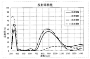
- FIG. 10 is a graph showing the reflectance distribution of concave surfaces according to Comparative Examples 1 to 4 and Examples 1 to 8.
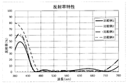
- 6 is a graph showing the reflectance distribution of convex surfaces in the visible region and the adjacent region according to Comparative Examples 1 to 4.
- 6 is a graph showing the reflectance distribution of a convex surface according to Comparative Examples 1 to 4 in a visible wavelength region, an adjacent region, and a partial wavelength region in the near infrared region.
- FIG. 3 is a view similar to FIG. 2 according to Examples 1 to 3.
- FIG. 4 is a view similar to FIG. 3 according to Examples 1 to 3. It is the same figure as FIG. 2 which concerns on Example 4-6. It is the same figure as FIG. 3 which concerns on Example 4-6. It is the same figure as FIG. 2 which concerns on Example 7-8. It is the same figure as FIG. 3 which concerns on Example 7-8.
- the base material may be any material, and preferably has translucency.
- a thermosetting resin is preferably used.
- an episulfide resin obtained by addition polymerization of an episulfide group and a polythiol and / or a sulfur-containing polyol, or a combination of this episulfide resin and another resin is used. Can be mentioned.
- the optical multilayer film has the following characteristics as appropriate.
- all the films have the following characteristics, and more preferably all the films have the same laminated structure. That is, the optical multilayer film has a structure having nine layers as a whole by alternately laminating low refractive index layers and high refractive index layers.
- the layer closest to the substrate is the first layer
- the odd layer is the low refractive index layer
- the even layer is the high refractive index layer.
- the low refractive index layer is a SiO 2 layer formed using silica (silicon dioxide, SiO 2 ), and the high refractive index layer is a ZrO 2 formed using zirconia (zircon dioxide, ZrO 2 ). Is a layer.
- the optical film thickness of the first layer (SiO 2 layer) is formed to be 0.120 ⁇ ⁇ / 4 or less, where the design wavelength is ⁇ (here, 500 nm).
- the optical thickness of the seventh layer (SiO 2 layer) is formed to be 0.450 ⁇ ⁇ / 4 or more, preferably 0.450 ⁇ ⁇ / 4 or more to 0.650 ⁇ ⁇ /. It is formed to be 4 or less.
- the optical thickness of the second layer is formed to be 0.400 ⁇ ⁇ / 4 or more, preferably 0.400 ⁇ ⁇ / 4 to 0.650 ⁇ ⁇ / It is formed to be 4 or less.
- the optical thickness of the third layer is 0.230 ⁇ ⁇ / 4 or more, preferably 0.230 ⁇ ⁇ / 4 or more and 0.560 ⁇ ⁇ / 4. It is formed to be as follows.
- the optical multilayer film is formed so that the average value of the single-sided reflectance is 20% or more in the wavelength range of 780 nm to 1500 nm in the near infrared region.
- the low refractive index layer and the high refractive index layer are formed by a vacuum vapor deposition method, an ion assist vapor deposition method, an ion plating method, a sputtering method, or the like.
- another type of film such as a hard coat film or an antifouling film (water-repellent film / oil-repellent film) may be added between the optical multilayer film and the substrate and at least one of the surfaces of the optical multilayer film.
- a hard coat film is used as a film (intermediate film) added between the optical multilayer film and the substrate, the hard coat film is preferably formed by uniformly applying a hard coat solution to the surface of the substrate.
- an organosiloxane resin preferably containing inorganic oxide fine particles can be used.
- the organosiloxane resin is preferably obtained by hydrolyzing and condensing alkoxysilane.
- Specific examples of the organosiloxane resin include ⁇ -glycidoxypropyltrimethoxysilane, ⁇ -glycidoxypropyltriethoxysilane, methyltrimethoxysilane, ethylsilicate, and combinations thereof.
- These hydrolysis-condensation products of alkoxysilane are produced by hydrolyzing the alkoxysilane compound or a combination thereof with an acidic aqueous solution such as hydrochloric acid.
- the material of the inorganic oxide fine particles zinc oxide, silicon dioxide (silica fine particles), aluminum oxide, titanium oxide (titania fine particles), zirconium oxide (zirconia fine particles), tin oxide, beryllium oxide, antimony oxide, oxidation
- examples thereof include single sols of tungsten and cerium oxide or a mixture of two or more of them.
- the diameter of the inorganic oxide fine particles is preferably 1 nm or more and 100 nm or less, and more preferably 1 nm or more and 50 nm or less from the viewpoint of ensuring the transparency of the hard coat film.
- the blending amount (concentration) of the inorganic oxide fine particles is 40% by weight (weight percent) or more and 60% of the total components of the hard coat film from the viewpoint of ensuring the appropriate degree of hardness and toughness in the hard coat film. It is preferable to occupy the weight% or less.
- at least one of acetylacetone metal salt and ethylenediaminetetraacetic acid metal salt can be added as a curing catalyst.
- a surfactant, a colorant, a solvent and the like can be added as necessary for imparting a transparent color.
- the physical thickness of the hard coat film is preferably 0.5 ⁇ m (micrometer) or more and 4.0 ⁇ m or less.
- a primer film may be added between the hard coat film and the substrate surface from the viewpoint of improving the adhesion of the hard coat film.
- the material of the primer film include a polyurethane resin, an acrylic resin, a methacrylic resin, an organic silicon resin, or a combination thereof.
- the primer film is preferably formed by uniformly applying a primer solution to the surface of the substrate.
- the primer liquid is a liquid obtained by mixing the above resin material and inorganic oxide fine particles in water or an alcohol-based solvent.
- the base material is preferably a plastic spectacle lens base material
- the optical product is a plastic spectacle lens.
- the reflectance is relatively high for both light in a predetermined wavelength range in the visible range such as blue light and near infrared rays, and other visible range light. With respect to, eyeglasses with reduced reflectivity and excellent durability can be manufactured.
- ⁇ Base material and interlayer film ⁇ These Examples or Comparative Examples are all plastic lenses, and their base materials are all made of thermosetting resin for spectacles, and have a circular shape with a standard size as a plastic lens for spectacles.
- S-2.00 is an aspheric lens base material, and more specifically, one of the following three types. That is, the first base material is made of thiourethane resin, the refractive index is 1.60, the Abbe number is 42, the specific gravity is 1.30 g / ml (gram per milliliter), and the glass transition temperature is 99. ° C (refractive index 1.60 substrate). Here, the glass transition temperature was measured with a differential scanning calorimeter, and so on.
- the second substrate is made of an episulfide resin obtained by addition polymerization of an episulfide group and at least one of a polythiol and a sulfur-containing polyol, and has a refractive index of 1.70, an Abbe number of 36, and a specific gravity. Is 1.41 g / ml, and the glass transition temperature is 67 ° C. (refractive index 1.70 substrate).
- the third base material is made of episulfide resin and has a refractive index of 1.76, an Abbe number of 30, a specific gravity of 1.49 g / ml, and a glass transition temperature of 59 ° C. (refractive index of 1.76). Base material).
- the end of the number is 1 (Example 1-1, Comparative Example 4-1, etc.).
- the number ends with 2 (Example 1-2, Comparative Example 4-2, etc.).
- those using a third base material have a number ending in 3 (Example 1-3, Comparative Example 4-3, etc.).
- a hard coat film formed by applying a hard coat solution was applied to both surfaces as an intermediate film.
- the hard coat film in contact with the plastic lens substrate was produced as follows. First, in a container, 206 g (gram) of methanol, 300 g of methanol-dispersed titania sol (manufactured by JGC Catalysts and Chemicals, solid content 30%), 60 g of ⁇ -glycidoxypropyltrimethoxysilane, ⁇ -glycidoxypropylmethyldi 30 g of ethoxysilane and 60 g of tetraethoxysilane were added dropwise, and a 0.01N (normality) aqueous hydrochloric acid solution was further added dropwise to the mixture and stirred for hydrolysis.
- a flow conditioner 0.5 g of a flow conditioner and 1.0 g of a catalyst were added and stirred at room temperature for 3 hours to prepare a hard coat solution.
- the hard coat solution was applied to each surface of the plastic lens substrate as follows. That is, the hard coat liquid was uniformly spread by a spin coat method and placed in an environment of 120 ° C. for 1.5 hours, whereby the hard coat liquid was heated and cured.
- the hard coat films thus formed all had a physical film thickness of 2.5 ⁇ m.
- the optical multilayer film on the concave surface side is composed of five general low refractive index layers on the intermediate film (the first layer L1 is the odd layer with the side closest to the substrate as the first layer L1). L1, L3, L5) and a high-refractive index layer (even layers L2, L4) as an alternate laminated film (antireflection film).
- the low refractive index layer of the concave optical multilayer film is a SiO 2 layer
- the high refractive index layer is a ZrO 2 layer
- the optical film thickness of each layer is that of each of Examples 1 to 8 to Comparative Examples 1 to 4. Is as shown in Table 1 below.
- the optical film thickness is generally expressed by the following equation (1).
- the optical film thickness values in Table 1 have the same light phase for each wavelength corresponding to 1/4 of the optical film thickness.
- the optical film thickness in equation (1) is divided by ⁇ / 4 in order to indicate how many times the design wavelength ⁇ of interest is 1 ⁇ 4.
- Optical film thickness (refractive index ⁇ physical film thickness) / design wavelength ⁇ (1)
- the optical multilayer film on the convex surface side was basically formed as follows on the intermediate film.
- the dome on which the substrate with the interlayer film was set was put into the vacuum device through the door, the door was closed, and the vacuum device was evacuated.
- the temperature in the vacuum apparatus was set to 60 ° C., and when the degree of vacuum in the vacuum apparatus reached 7.0E-04 Pa (Pascal), the formation of the optical multilayer film was started. Note that 7.0E-04 represents 7.0 ⁇ 10 ⁇ 4 .
- the film In forming the film, first, in order to improve the adhesion between the intermediate film and the optical multilayer film to be formed, oxygen ions are irradiated to the substrate surface (intermediate film) for 60 seconds to activate the surface. It was given. And the low refractive index material and the high refractive index material were vapor-deposited alternately, and the optical multilayer film which has a low refractive index layer and a high refractive index layer alternately was formed into a film. Silica (“SiO 2 ” manufactured by Canon Optron Co., Ltd.) was used as the low refractive index material, and the film forming rate of the low refractive index material was 10.0 ⁇ / s (angstrom per second).
- the refractive index with respect to light having a wavelength of 550 nm in the thus formed low refractive index layer was 1.4815.
- As the high refractive index material zirconia (“ZrO 2 ” manufactured by the same company) was used, and the film forming rate of the high refractive index material was 6.0 ⁇ / s.
- the refractive index with respect to light having a wavelength of 550 nm in the thus formed high refractive index layer was 2.0743.
- the optical film thickness of each layer in Comparative Examples 1 to 4 (divided by ⁇ / 4) is as shown in the upper part of the following Table 2.
- the optical multilayer film (convex surface) of Comparative Example 1 has a seven-layer structure, and the optical film thickness of the first layer L1 (SiO 2 layer) counted from the substrate side is not less than 0.120 ⁇ ⁇ / 4.
- the optical thickness of the outermost seventh layer L7 (SiO 2 layer) is not 0.450 ⁇ ⁇ / 4 or more, and the optical thickness of the third layer L3 (SiO 2 layer) is 0.230 ⁇ ⁇ / 4. Not more.
- the optical multilayer film (convex surface) of Comparative Example 2 has a nine-layer structure, but the optical film thickness of the first layer L1 (SiO 2 layer) is not less than 0.120 ⁇ ⁇ / 4.
- the optical multilayer film (convex surface) of Comparative Example 3 has a nine-layer structure, but the optical film thickness of the first layer L1 (SiO 2 layer) is not less than 0.120 ⁇ ⁇ / 4. Furthermore, the optical multilayer film (convex surface) of Comparative Example 4 has an eight-layer structure in which the first layer L1 is a ZrO 2 layer.
- each of the optical multilayer films (convex surfaces) of Examples 1 to 8 has a nine-layer structure, and the optical thickness of the first layer L1 (SiO 2 layer) is 0.120 ⁇ ⁇ / 4 or less, the optical thickness of the seventh layer L7 (SiO 2 layer) is 0.450 ⁇ ⁇ / 4 or more and 0.650 ⁇ ⁇ / 4 or less, and the optical film of the second layer L2 (ZrO 2 layer) The thickness is 0.400 ⁇ ⁇ / 4 to 0.650 ⁇ ⁇ / 4, and the optical thickness of the third layer L3 (SiO 2 layer) is 0.230 ⁇ ⁇ / 4 to 0.560 ⁇ ⁇ . / 4 or less.
- Comparative Examples 1-1 to 4-3 the appearance after forming the optical multilayer film (convex surface) was visually confirmed. The results are shown in the middle part of Table 2 above. Further, in Examples 1-1 to 4-3 and 5-1 to 8-3, the appearance after the optical multilayer film (convex surface) was formed was visually confirmed. The results are shown in the middle of Tables 3 and 4 above.
- Comparative Example 1 in Comparative Example 1-2 (refractive index 1.70 base material) and Comparative Example 1-3 (refractive index 1.76 base material), many linear cracks were observed on the convex surface. In other comparative examples or examples, no abnormalities such as cracks were observed in appearance.
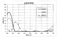
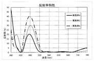
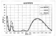
- FIG. 2 shows the distribution relating to the visible region (wavelength 400 nm or more and 780 nm or less) and the adjacent region (total wavelength 380 nm or more and 780 nm or less), and FIG. 3 shows the visible region, the adjacent region, and the near infrared region.
- FIG. 4 shows the distribution relating to the visible region and the adjacent region (total wavelength 380 nm to 780 nm)
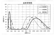
- FIG. 5 shows the visible region, the near infrared region, and the adjacent region (total wavelength 350 nm to 1500 nm).
- the distribution according to the following) is shown.
- the convex reflectance distributions of Examples 2 to 3 are also shown in FIGS.
- the convex reflectance distributions of Examples 4 to 6 are shown in FIGS. 6 and 7, and the convex reflectance distributions of Examples 7 to 8 are shown in FIGS.
- the average value of the convex reflectance in the near infrared region in these comparative examples is shown in the lower part of Table 2 above, and the near infrared region reflectance in these examples is It is shown in the lower part of Table 3 and Table 4 above.
- the reflectance in the wavelength region of 400 nm ⁇ 50 nm is higher than the reflectance in the visible region excluding that region, and the filter reflects light having a wavelength of 400 nm or around that. Yes.
- the average value (near-infrared reflectance) of the reflectance in the near-infrared region of interest is also relatively high (around 23%). It has a reflection function.
- the near-infrared region reflectance is as low as about 7% and does not have a sufficient near-infrared reflecting function.
- Example 1 the reflectance in the wavelength region of 400 nm ⁇ 50 nm is higher than the reflectance in the visible region excluding that region, and the reflectance (maximum value) of light with a wavelength of 400 nm is particularly 71% and 70%. %, And the reflectance in the wavelength range of 400 nm to 420 nm, which is the short wavelength side in the visible range, exceeds 50% in the entire region. Furthermore, in the reflectance distribution of Example 1, there is a mountain having a maximum value (44%) at a wavelength of 1100 nm in the focused infrared region, and the near-infrared reflectance is as high as 23.42%.
- the reflectance in the wavelength region of 400 nm ⁇ 50 nm is higher than the reflectance in the visible region except that region, and the reflectance (maximum value) of light with a wavelength of 400 nm is particularly 50%. Moreover, the reflectance in the wavelength region of 400 nm or more and 420 nm or less, which is the short wavelength side of the visible region, exceeds 30% in the entire region. Furthermore, in the reflectance distribution of Example 2, there is a mountain having a maximum value (51%) at a wavelength of 930 nm in the infrared region of interest, and the near infrared reflectance is as high as 24.63%.
- Example 3 the reflectance in the wavelength region of 420 nm or more and 500 nm or less is higher than the reflectance in the visible region excluding that region, and particularly the reflectance (maximum value) of light with a wavelength of 450 nm is 35%. It has become. Furthermore, in the reflectance distribution of Example 3, there is a mountain having a maximum value (51%) at a wavelength of 1070 nm in the infrared region of interest, and the near-infrared reflectance is as high as 26.15%.
- Example 4 the reflectance in the wavelength region of 440 nm or more and 520 nm or less is higher than the reflectance in the visible region of more than 520 nm and 730 nm or less, and in particular, the reflectance of light with a wavelength of 480 nm (maximum) Value) is 20%. Furthermore, in the reflectance distribution of Example 4, there is a peak having a maximum value (47%) at a wavelength of 1130 nm in the infrared region of interest, and the near-infrared reflectance is as high as 24.97%.
- Example 5 the reflectance in the wavelength region of 450 nm or more and 530 nm or less is higher than the reflectance in the visible region exceeding 540 nm, and particularly the reflectance (maximum value) of light having a wavelength of 480 nm is 30%. It has become. Furthermore, in the reflectance distribution of Example 5, there is a mountain having a maximum value (49%) at a wavelength of 1130 nm in the infrared region of interest, and the near-infrared reflectance is as high as 26.17%.
- Example 6 the reflectance in the wavelength region of 440 nm or more and 530 nm or less is higher than the reflectance in the visible region exceeding 530 nm, and particularly the reflectance (maximum value) of light having a wavelength of 480 nm is 40%. It has become. Furthermore, in the reflectance distribution of Example 6, there is a peak having a maximum value (45%) at a wavelength of 1130 nm in the infrared region of interest, and the near-infrared reflectance is as high as 22.99%.
- Example 7 the reflectance in the wavelength region of 390 nm to 450 nm is higher than the reflectance in the visible region of more than 450 nm and not more than 760 nm. Value) is 25%. Furthermore, in the reflectance distribution of Example 7, there is a peak having a maximum value (53%) at a wavelength of 990 nm in the infrared region of interest, and the near infrared reflectance is as high as 25.85%. Moreover, in Example 8, each reflectance in the wavelength region of 400 nm or more and 500 nm or less and the wavelength region of 550 nm or more and 700 nm or less is higher than the reflectance in the wavelength region of more than 500 nm and less than 550 nm.
- the reflectance of light (first maximum value) is 11%, and the reflectance of light with a wavelength of 620 nm (second maximum value) is also 11%. Furthermore, in the reflectance distribution of Example 8, there is a mountain having a maximum value (54%) at a wavelength of 910 nm in the focused infrared region, and the near infrared reflectance is as high as 26.45%.
- the lens was put into a sunshine weather meter (S80B, manufactured by Suga Test Instruments Co., Ltd.) for 60 hours (hr), and then, using the cellophane tape applied to the newly formed grid formation site, as before. The number of squares that peeled off was counted. Thereafter, similarly, the lens is put into the sunshine weather meter for 60 hours, and the number of squares peeled off is confirmed. Such throwing and checking are performed every 60 hours from the first feeding until the confirmation after 240 hours feeding. Repeated.
- the constant humidity and constant temperature test was conducted using a constant humidity and constant temperature tester (LHU-113 manufactured by Espec Corp.). The tank of the tester is set to a temperature of 60 ° C. and a relative humidity of 95% RH, and each lens is inserted into the tank. It was visually confirmed whether or not appearance abnormalities such as edema, discoloration, and cracks occurred.
- Comparative Examples 1-1, 2-1, 3-1, 4-1 to Examples 1-1, 2-1, 3-1, 4-1, 5 relating to 1.60 substrates Cracks were observed after lapse of 7 days in -1,6-1,7-1,8-1, but no cracks were observed after 7 days in other comparative examples and examples. If cracks do not occur even after being exposed to a constant humidity and temperature environment for 3 days, it can be said that they have sufficient durability (heat resistance, moisture resistance). It has high durability. The reason why cracks occurred after 7 days in the 1.60 base material is considered to be due to the higher expansion coefficient of the base material compared to other base materials.
- Comparative Example 1 the optical film thickness of the second ZrO 2 layer is 0.400 ⁇ ⁇ / 4 or more and 0.650 ⁇ ⁇ / 4 or less. A high reflectance is ensured.
- Comparative Example 1 has a seven-layer structure, and the third SiO 2 layer is 0.230 ⁇ ⁇ / 4 or less, and in Comparative Examples 1-2 and 1-3, the film was formed. A linear crack has occurred.
- Comparative Example 2 has a nine-layer structure, and the optical thickness of the second ZrO 2 layer is 0.400 ⁇ ⁇ / 4 to 0.650 ⁇ ⁇ / 4, and the third SiO 2 layer The optical film thickness is 0.230 ⁇ ⁇ / 4 or more and 0.560 ⁇ ⁇ / 4 or less, and the optical thickness of the seventh SiO 2 layer is 0.450 ⁇ ⁇ / 4 or more and 0.650 ⁇ ⁇ / 4. Due to the following, high reflectance is ensured both in the near-infrared region and the blue region in the visible region, and the occurrence of cracks during film formation is avoided.
- Comparative Example 2 the optical film thickness of the first SiO 2 layer is 0.350 ⁇ ⁇ / 4 and exceeds 0.120 ⁇ ⁇ / 4. The film is peeled off.
- Comparative Example 3 has a nine-layer structure similar to Comparative Example 2, and the optical thickness of the first SiO 2 layer is 0.228 ⁇ ⁇ / 4, which is even thinner than Comparative Example 2.
- Comparative Example 4 has an eight-layer structure in which the ZrO 2 layer is the first layer, and the optical film thickness of each layer is thin in order to ensure the reflectance in the blue region, but the reflectance in the infrared region is 7%. Only a degree can be secured.
- each of Examples 1 to 8 has a nine-layer structure, and the optical thickness of the first SiO 2 layer counted from the substrate is 0.120 ⁇ ⁇ / 4 or less, and the second layer The optical thickness of the ZrO 2 layer is 0.400 ⁇ ⁇ / 4 to 0.650 ⁇ ⁇ / 4, and the optical thickness of the third SiO 2 layer is 0.230 ⁇ ⁇ / 4 to 0.
- the optical thickness of the seventh SiO 2 layer is 0.450 ⁇ ⁇ / 4 or more and 0.650 ⁇ ⁇ / 4 or less, so that a high reflectance in the near infrared region ( The average reflectance of single-sided reflectance at 780 nm or more and 1500 nm is 20% or more, and the high reflectance of the partial region of the visible region is low reflectance of other visible regions (preferably an average of 3% or less, more preferably 3 in total) % Or less, more preferably 1% or less on average, and even more preferably 1% or less overall) Rutotomoni, (non-destructive in non-releasing and constant temperature and humidity test in weathering accelerated adhesion test) durability is ensured.
- Examples 1 and 2 light in the short wavelength range (400 nm to 420 nm) in the visible range is cut with high reflectance along with near infrared rays, and the degree of cut is 71%, 50% reflectance at a wavelength of 400 nm. % And variable.
- Such short-wavelength (blue) light has higher energy than visible light, and if the amount reaching the eye is reduced, the eye is protected. If it produces, the spectacles which protect eyes from blue light and near-infrared will be provided.
- Example 3 the light of the partial region (420 nm or more and 500 nm or less) in a visible region is cut by high reflectance with near infrared rays.
- the maximum value of the reflectance in the partial area is 35% at a wavelength of 450 nm, and the light of 450 nm where the maximum value of the spectral intensity distribution of LED illumination is located and the light of the adjacent wavelength are cut together with the near infrared rays. . Therefore, by producing glasses according to Example 3, it is possible to provide glasses in which the eyes are protected and a balanced field of view is secured under LED illumination.
- an LED lighting cover having a film similar to that of Example 3 can be manufactured to provide a cover in which the LED lighting light can protect the eyes and the color is adjusted.
- Examples 4 to 6 light in a partial region (440 nm or more and 520 nm or less) in the visible region is cut with high reflectance along with near infrared rays.
- the maximum values of the reflectance in the partial region are 20%, 30%, and 40% at a wavelength of 480 nm, and it is possible to provide a lens that cuts off light of the wavelength 480 nm and its adjacent region, and near infrared rays.
- the body clock is distorted when light in the wavelength range of 480 nm or its adjacent region is exposed at night (before going to bed).
- the light can be cut together with near infrared rays.
- the degree of light cut rate ie wavelength
- the degree (size) is variable in Examples 4 to 6, and the above needs are satisfied.
- a television etc. which use the display of portable electronic devices including a smart phone, a computer display, LED as a backlight, for example.
- Example 7 light in the blue region (390 nm or more and 450 nm or less) in the visible region is cut with high reflectance along with near infrared rays.
- the maximum value of the reflectance in the blue region was located at a wavelength of 400 nm.
- the maximum value was located at 420 nm.
- the balance between the eye protection performance against blue light and the visibility such as hue is adjusted by changing the position of the maximum value.
- Example 8 light in two partial regions in the visible region (wavelength region of 400 nm or more and 500 nm or less, 550 nm or more and 700 nm or less) is cut with high reflectance along with near infrared rays.
- Example 8 similarly to Example 3, it has a maximum value of reflectance at a wavelength of 450 nm. If only the light (blue light) of the wavelength or the wavelength in the adjacent region is cut out of the visible light, the transmitted light color (transmission color) exhibits a complementary yellow color of blue, and the degree of the yellow color is reduced. Therefore, in Example 8, light having a wavelength of 620 nm related to the yellow region and light having a wavelength in the adjacent region (yellow light) are also cut with high reflectance, and the transmitted color approaches white.
- the optical multilayer film has a nine-layer structure, the optical thickness of the first SiO 2 layer counted from the base material is 0.120 ⁇ ⁇ / 4 or less, and the second ZrO 2 layer
- the optical film thickness is 0.400 ⁇ ⁇ / 4 or more (preferably 0.650 ⁇ ⁇ / 4 or less)
- the optical film thickness of the third SiO 2 layer is 0.230 ⁇ ⁇ / 4 or more (preferably 0.560 ⁇ ⁇ / 4 or less)
- the optical thickness of the seventh SiO 2 layer is 0.450 ⁇ ⁇ / 4 or more (preferably 0.650 ⁇ ⁇ / 4 or less).
Landscapes
- Physics & Mathematics (AREA)
- General Physics & Mathematics (AREA)
- Optics & Photonics (AREA)
- Health & Medical Sciences (AREA)
- Ophthalmology & Optometry (AREA)
- Chemical & Material Sciences (AREA)
- Inorganic Chemistry (AREA)
- General Health & Medical Sciences (AREA)
- Spectroscopy & Molecular Physics (AREA)
- Surface Treatment Of Optical Elements (AREA)
- Eyeglasses (AREA)
- Optical Elements Other Than Lenses (AREA)
- Optical Filters (AREA)
Priority Applications (4)
| Application Number | Priority Date | Filing Date | Title |
|---|---|---|---|
| CN201780050146.9A CN109564306B (zh) | 2016-08-26 | 2017-08-01 | 光学制品以及塑料眼镜镜片和眼镜 |
| EP17843336.3A EP3489727B1 (en) | 2016-08-26 | 2017-08-01 | Optical product, plastic eyeglass lens, and eyeglasses |
| KR1020197005281A KR102410405B1 (ko) | 2016-08-26 | 2017-08-01 | 광학 제품 및 플라스틱 안경 렌즈 및 안경 |
| US16/254,873 US11668957B2 (en) | 2016-08-26 | 2019-01-23 | Optical product, plastic spectacle lens, and spectacles |
Applications Claiming Priority (2)
| Application Number | Priority Date | Filing Date | Title |
|---|---|---|---|
| JP2016-165936 | 2016-08-26 | ||
| JP2016165936A JP2018031975A (ja) | 2016-08-26 | 2016-08-26 | 光学製品並びにプラスチック眼鏡レンズ及び眼鏡 |
Related Child Applications (1)
| Application Number | Title | Priority Date | Filing Date |
|---|---|---|---|
| US16/254,873 Continuation US11668957B2 (en) | 2016-08-26 | 2019-01-23 | Optical product, plastic spectacle lens, and spectacles |
Publications (1)
| Publication Number | Publication Date |
|---|---|
| WO2018037850A1 true WO2018037850A1 (ja) | 2018-03-01 |
Family
ID=61246583
Family Applications (1)
| Application Number | Title | Priority Date | Filing Date |
|---|---|---|---|
| PCT/JP2017/027848 Ceased WO2018037850A1 (ja) | 2016-08-26 | 2017-08-01 | 光学製品並びにプラスチック眼鏡レンズ及び眼鏡 |
Country Status (6)
| Country | Link |
|---|---|
| US (1) | US11668957B2 (enExample) |
| EP (1) | EP3489727B1 (enExample) |
| JP (1) | JP2018031975A (enExample) |
| KR (1) | KR102410405B1 (enExample) |
| CN (1) | CN109564306B (enExample) |
| WO (1) | WO2018037850A1 (enExample) |
Cited By (3)
| Publication number | Priority date | Publication date | Assignee | Title |
|---|---|---|---|---|
| WO2020067407A1 (ja) * | 2018-09-28 | 2020-04-02 | ホヤ レンズ タイランド リミテッド | 眼鏡レンズ |
| WO2020066532A1 (ja) * | 2018-09-25 | 2020-04-02 | 東海光学株式会社 | 眼鏡レンズ及び眼鏡 |
| EP4102264A1 (en) | 2021-06-09 | 2022-12-14 | Essilor International | Optical lens having an antireflection coating reflecting harmful blue light and nir radiation |
Families Citing this family (5)
| Publication number | Priority date | Publication date | Assignee | Title |
|---|---|---|---|---|
| WO2019103105A1 (ja) * | 2017-11-24 | 2019-05-31 | ホヤ レンズ タイランド リミテッド | 眼鏡レンズおよび眼鏡 |
| CN110927989B (zh) * | 2019-12-18 | 2021-08-24 | 厦门美澜光电科技有限公司 | 一种埃米抗氧化抗红外光带图案镜片及其制备方法 |
| JP7399984B2 (ja) * | 2019-12-27 | 2023-12-18 | ホヤ レンズ タイランド リミテッド | 眼鏡レンズ |
| CN111308585A (zh) * | 2020-03-06 | 2020-06-19 | 江苏黄金屋光学眼镜有限公司 | 一种镜片防蓝光、红外光的方法 |
| WO2022258793A1 (en) * | 2021-06-09 | 2022-12-15 | Essilor International | Optical lens having an antireflection coating reflecting blue light |
Citations (3)
| Publication number | Priority date | Publication date | Assignee | Title |
|---|---|---|---|---|
| JP2014056215A (ja) * | 2012-09-14 | 2014-03-27 | Ricoh Imaging Co Ltd | 反射防止膜、それを用いた光学部材、及び光学機器 |
| WO2015080160A1 (ja) * | 2013-11-26 | 2015-06-04 | ホヤ レンズ タイランド リミテッド | 眼鏡レンズ |
| WO2015137282A1 (ja) * | 2014-03-14 | 2015-09-17 | ホヤ レンズ タイランド リミテッド | ミラーコートレンズ |
Family Cites Families (15)
| Publication number | Priority date | Publication date | Assignee | Title |
|---|---|---|---|---|
| US5871268A (en) * | 1996-10-15 | 1999-02-16 | Escalon Medical Corporation | Cool white light source |
| US6682193B1 (en) * | 1998-12-30 | 2004-01-27 | Sola International Holdings Ltd. | Wide field spherical lenses and protective eyewear |
| JP5211289B2 (ja) * | 2005-11-01 | 2013-06-12 | 東海光学株式会社 | 可視域用プラスチックレンズ |
| JP2007127861A (ja) | 2005-11-04 | 2007-05-24 | Kddi Corp | 付属情報埋め込み装置および再生装置 |
| JP2007220832A (ja) * | 2006-02-15 | 2007-08-30 | Matsushita Electric Ind Co Ltd | 固体撮像装置及びカメラ |
| JP2012128135A (ja) * | 2010-12-15 | 2012-07-05 | Seiko Epson Corp | 光学物品およびその製造方法 |
| EP3561580A1 (en) * | 2011-10-31 | 2019-10-30 | Hoya Corporation | Eyeglass lens |
| US9201172B2 (en) | 2012-09-14 | 2015-12-01 | Ricoh Imaging Company, Ltd. | Anti-reflection coating, optical member having it, and optical equipment comprising such optical member |
| US9927557B2 (en) * | 2012-09-28 | 2018-03-27 | Hoya Corporation | Eyeglass lens |
| CN203331491U (zh) * | 2013-07-04 | 2013-12-11 | 威海蓝星玻璃股份有限公司 | 一种表面改性玻璃 |
| CN105829798B (zh) * | 2013-12-23 | 2019-09-10 | 依视路国际公司 | 具有滤光功能的头戴式显示器 |
| JP6451057B2 (ja) | 2014-02-04 | 2019-01-16 | 東海光学株式会社 | 可視域反射防止近赤外域透過抑制光学製品並びに眼鏡レンズ及び眼鏡 |
| CN204028389U (zh) * | 2014-08-27 | 2014-12-17 | 南京施密特光学仪器有限公司 | 一种自清洁超宽带增透膜镜片 |
| JP6581653B2 (ja) * | 2015-05-11 | 2019-09-25 | 株式会社ニコン・エシロール | 眼鏡レンズ |
| CN105759334A (zh) * | 2016-02-01 | 2016-07-13 | 张汉新 | 一种滤光膜及一种灯具滤光装置 |
-
2016
- 2016-08-26 JP JP2016165936A patent/JP2018031975A/ja active Pending
-
2017
- 2017-08-01 EP EP17843336.3A patent/EP3489727B1/en active Active
- 2017-08-01 WO PCT/JP2017/027848 patent/WO2018037850A1/ja not_active Ceased
- 2017-08-01 KR KR1020197005281A patent/KR102410405B1/ko active Active
- 2017-08-01 CN CN201780050146.9A patent/CN109564306B/zh active Active
-
2019
- 2019-01-23 US US16/254,873 patent/US11668957B2/en active Active
Patent Citations (3)
| Publication number | Priority date | Publication date | Assignee | Title |
|---|---|---|---|---|
| JP2014056215A (ja) * | 2012-09-14 | 2014-03-27 | Ricoh Imaging Co Ltd | 反射防止膜、それを用いた光学部材、及び光学機器 |
| WO2015080160A1 (ja) * | 2013-11-26 | 2015-06-04 | ホヤ レンズ タイランド リミテッド | 眼鏡レンズ |
| WO2015137282A1 (ja) * | 2014-03-14 | 2015-09-17 | ホヤ レンズ タイランド リミテッド | ミラーコートレンズ |
Cited By (16)
| Publication number | Priority date | Publication date | Assignee | Title |
|---|---|---|---|---|
| US11966102B2 (en) | 2018-09-25 | 2024-04-23 | Tokai Optical Co., Ltd. | Spectacle lens and spectacles |
| KR20210062017A (ko) * | 2018-09-25 | 2021-05-28 | 토카이 옵티칼 주식회사 | 안경 렌즈 및 안경 |
| JP2020052135A (ja) * | 2018-09-25 | 2020-04-02 | 東海光学株式会社 | 眼鏡レンズ及び眼鏡 |
| CN112740097A (zh) * | 2018-09-25 | 2021-04-30 | 东海光学株式会社 | 眼镜镜片和眼镜 |
| KR102752481B1 (ko) * | 2018-09-25 | 2025-01-10 | 토카이 옵티칼 주식회사 | 안경 렌즈 및 안경 |
| EP3842854A4 (en) * | 2018-09-25 | 2022-06-08 | Tokai Optical Co., Ltd. | LENS AND GLASSES |
| WO2020066532A1 (ja) * | 2018-09-25 | 2020-04-02 | 東海光学株式会社 | 眼鏡レンズ及び眼鏡 |
| JP7136907B2 (ja) | 2018-09-28 | 2022-09-13 | ホヤ レンズ タイランド リミテッド | 眼鏡レンズ |
| CN112840263A (zh) * | 2018-09-28 | 2021-05-25 | 豪雅镜片泰国有限公司 | 眼镜镜片 |
| JPWO2020067407A1 (ja) * | 2018-09-28 | 2021-08-30 | ホヤ レンズ タイランド リミテッドHOYA Lens Thailand Ltd | 眼鏡レンズ |
| KR102582202B1 (ko) | 2018-09-28 | 2023-09-22 | 호야 렌즈 타일랜드 리미티드 | 안경 렌즈 |
| WO2020067407A1 (ja) * | 2018-09-28 | 2020-04-02 | ホヤ レンズ タイランド リミテッド | 眼鏡レンズ |
| CN112840263B (zh) * | 2018-09-28 | 2024-05-07 | 豪雅镜片泰国有限公司 | 眼镜镜片 |
| US11988902B2 (en) | 2018-09-28 | 2024-05-21 | Hoya Lens Thailand Ltd. | Spectacle lens |
| KR20210059770A (ko) * | 2018-09-28 | 2021-05-25 | 호야 렌즈 타일랜드 리미티드 | 안경 렌즈 |
| EP4102264A1 (en) | 2021-06-09 | 2022-12-14 | Essilor International | Optical lens having an antireflection coating reflecting harmful blue light and nir radiation |
Also Published As
| Publication number | Publication date |
|---|---|
| CN109564306A (zh) | 2019-04-02 |
| CN109564306B (zh) | 2022-05-10 |
| JP2018031975A (ja) | 2018-03-01 |
| US11668957B2 (en) | 2023-06-06 |
| EP3489727B1 (en) | 2022-07-20 |
| KR20190042012A (ko) | 2019-04-23 |
| EP3489727A1 (en) | 2019-05-29 |
| US20190155058A1 (en) | 2019-05-23 |
| EP3489727A4 (en) | 2020-03-25 |
| KR102410405B1 (ko) | 2022-06-17 |
Similar Documents
| Publication | Publication Date | Title |
|---|---|---|
| WO2018037850A1 (ja) | 光学製品並びにプラスチック眼鏡レンズ及び眼鏡 | |
| KR102232170B1 (ko) | 광학 제품 및 안경 렌즈 및 안경 | |
| CN103026268B (zh) | 光学制品和眼镜塑料镜片 | |
| EP3118658B1 (en) | Mirror-coated lens | |
| CN103329013B (zh) | 包括在紫外区和可见光区中具有低反射的抗反射涂层的光学制品 | |
| CN109844573A (zh) | 在近红外区和蓝光区具有高反射的光学制品 | |
| CN109642965A (zh) | 包含反射性抗磨损多层涂层的眼科镜片和用于制造所述镜片的方法 | |
| KR102241953B1 (ko) | 광학 제품 및 안경 렌즈 및 안경 | |
| WO2019009127A1 (ja) | プラスチック光学製品並びにプラスチック眼鏡レンズ及び眼鏡 | |
| CN108431678A (zh) | 眼镜镜片及眼镜 | |
| JP2018141847A (ja) | プラスチック眼鏡レンズ及び眼鏡 | |
| WO2017002965A1 (ja) | 光学製品並びにプラスチックレンズ及び眼鏡 | |
| CN112534339B (zh) | 眼镜透镜以及眼镜 | |
| JP2025128868A (ja) | 眼鏡レンズ及び眼鏡 | |
| TW202346976A (zh) | 眼鏡用鏡片 | |
| JP2020052135A (ja) | 眼鏡レンズ及び眼鏡 |
Legal Events
| Date | Code | Title | Description |
|---|---|---|---|
| 121 | Ep: the epo has been informed by wipo that ep was designated in this application |
Ref document number: 17843336 Country of ref document: EP Kind code of ref document: A1 |
|
| ENP | Entry into the national phase |
Ref document number: 20197005281 Country of ref document: KR Kind code of ref document: A |
|
| NENP | Non-entry into the national phase |
Ref country code: DE |
|
| ENP | Entry into the national phase |
Ref document number: 2017843336 Country of ref document: EP Effective date: 20190221 |