WO2018037773A1 - マットレスずれ止め具、および寝台装置 - Google Patents
マットレスずれ止め具、および寝台装置 Download PDFInfo
- Publication number
- WO2018037773A1 WO2018037773A1 PCT/JP2017/025953 JP2017025953W WO2018037773A1 WO 2018037773 A1 WO2018037773 A1 WO 2018037773A1 JP 2017025953 W JP2017025953 W JP 2017025953W WO 2018037773 A1 WO2018037773 A1 WO 2018037773A1
- Authority
- WO
- WIPO (PCT)
- Prior art keywords
- bed
- mattress
- fitted
- short
- restriction
- Prior art date
Links
Images


Classifications
-
- A—HUMAN NECESSITIES
- A47—FURNITURE; DOMESTIC ARTICLES OR APPLIANCES; COFFEE MILLS; SPICE MILLS; SUCTION CLEANERS IN GENERAL
- A47C—CHAIRS; SOFAS; BEDS
- A47C20/00—Head -, foot -, or like rests for beds, sofas or the like
- A47C20/04—Head -, foot -, or like rests for beds, sofas or the like with adjustable inclination
-
- A—HUMAN NECESSITIES
- A47—FURNITURE; DOMESTIC ARTICLES OR APPLIANCES; COFFEE MILLS; SPICE MILLS; SUCTION CLEANERS IN GENERAL
- A47C—CHAIRS; SOFAS; BEDS
- A47C21/00—Attachments for beds, e.g. sheet holders, bed-cover holders; Ventilating, cooling or heating means in connection with bedsteads or mattresses
- A47C21/02—Holders for loose bed elements, e.g. sheet holders; bed cover holders
-
- A—HUMAN NECESSITIES
- A61—MEDICAL OR VETERINARY SCIENCE; HYGIENE
- A61G—TRANSPORT, PERSONAL CONVEYANCES, OR ACCOMMODATION SPECIALLY ADAPTED FOR PATIENTS OR DISABLED PERSONS; OPERATING TABLES OR CHAIRS; CHAIRS FOR DENTISTRY; FUNERAL DEVICES
- A61G7/00—Beds specially adapted for nursing; Devices for lifting patients or disabled persons
- A61G7/002—Beds specially adapted for nursing; Devices for lifting patients or disabled persons having adjustable mattress frame
- A61G7/015—Beds specially adapted for nursing; Devices for lifting patients or disabled persons having adjustable mattress frame divided into different adjustable sections, e.g. for Gatch position
-
- A—HUMAN NECESSITIES
- A61—MEDICAL OR VETERINARY SCIENCE; HYGIENE
- A61G—TRANSPORT, PERSONAL CONVEYANCES, OR ACCOMMODATION SPECIALLY ADAPTED FOR PATIENTS OR DISABLED PERSONS; OPERATING TABLES OR CHAIRS; CHAIRS FOR DENTISTRY; FUNERAL DEVICES
- A61G7/00—Beds specially adapted for nursing; Devices for lifting patients or disabled persons
- A61G7/05—Parts, details or accessories of beds
Definitions
- the present invention relates to a mattress slip stopper and a bed apparatus.
- a mattress slip stopper for example, as shown in Patent Document 1 below, a mattress slip stopper that regulates horizontal displacement of a mattress on a bed is known.
- the present invention has been made in view of the above-described circumstances, and an object of the present invention is to provide a mattress slip stopper and a bed apparatus that can reliably regulate the horizontal displacement of the mattress with respect to the bed.
- An aspect according to the present invention is a mattress displacement stopper that restricts the displacement of the mattress on the bed, and a longitudinal restriction portion that regulates the displacement of the mattress in the longitudinal direction of the bed;
- a short-side restricting portion that restricts displacement of the mattress in the short-side direction, and a relative position between the long-side restricting portion and the short-side restricting portion is fixed.
- the relative position between the long restricting portion and the short restricting portion is fixed, the external force from the mattress along one of the long direction and the short direction is applied to the long restricting portion and the short restricting portion. It can be received not only by any one of the hand regulating portions but also by the other. For this reason, even when the external force transmitted from the mattress is large, the external force can be reliably received by the mattress slip stopper. Thereby, the horizontal displacement of the mattress with respect to the bed can be reliably controlled. Further, the relative position between the long restriction part and the short restriction part is fixed.
- one mattress slip stopper can effectively effect the displacement in both the longitudinal direction and the short direction of the bed with respect to the bed. Can be regulated. Thereby, the number of parts can be reduced.
- the longitudinal restriction portion and the short side restriction portion may be integrally formed.
- the long restriction portion and the short restriction portion are integrally formed, there is no need to provide a member for connecting the long restriction portion and the short restriction portion to each other, and the mattress misalignment stopper can be strengthened with a simple configuration. Can be formed.
- the mattress slip stopper is firmly attached to the bed as compared with the configuration in which only one is attached to the bed. Can be attached to.
- a bed apparatus includes the bed and the mattress slip prevention device according to any one of (1) to (3) above.
- the mattress detent tool is attached to the bed as compared with the configuration in which only one is attached to the bed. Can be firmly attached.
- the 1st to-be-fitted part and the 2nd to-be-fitted part which each of a 1st attachment part and a 2nd attachment part fit are provided in the bed apparatus, the mattress deviation stopper to the bed apparatus is provided. Mounting can be performed easily.
- the direction in which the first attachment portion is fitted to the first fitted portion and the direction in which the second attachment portion is fitted to the second fitted portion are different from each other. For this reason, the direction in which the first attachment portion is removed from the first fitted portion and the direction in which the second attachment portion is removed from the second fitted portion are different from each other. Therefore, even if an external force is unexpectedly applied to the mattress slip stopper, the fitting between the first attachment portion and the first fitted portion and the fitting between the second attachment portion and the second fitted portion are not performed. Simultaneous release can be suppressed.
- the horizontal displacement of the mattress with respect to the bed can be reliably regulated.
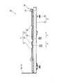
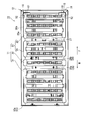
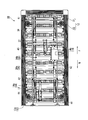
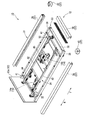
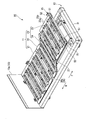
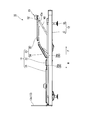
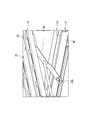
- FIG. 1 It is a perspective view of the bed apparatus concerning one embodiment of the present invention. It is a side view of the bed apparatus shown in FIG. It is a top view of the bed apparatus shown in FIG. It is a bottom view of the bed apparatus shown in FIG. It is a disassembled perspective view of the bed apparatus shown in FIG. 1, and is a view showing a state where a bottom is removed. It is a perspective view which shows a leg raising state in the bed apparatus shown in FIG. It is a side view of the bed apparatus shown in FIG. It is an expansion perspective view of the principal part in the bed apparatus shown in FIG. It is an expansion perspective view of the mattress slip stopper of the bed apparatus shown in FIG.
- the mattress slip stopper 15 and the bed apparatus 10 will be described below with reference to FIGS.
- the bed apparatus 10 can be used, for example, in a medical environment (including a care environment) or a general home.
- an arrow H indicates a direction that becomes the head side H when the person (user) sleeps
- an arrow F indicates a direction that becomes the foot side F when the person sleeps.
- the horizontal direction orthogonal to the front-rear direction which is the direction of arrows H and F, may be referred to as the left-right direction.
- the front-rear direction and the left-right direction are both directions along the horizontal direction.
- the bed apparatus 10 includes a bed 11, a support frame 12, a board 13, and a drive mechanism 14.
- the bed apparatus 10 is a so-called electric bed that uses electric power as a power source.
- the bed 11 is longer in the front-rear direction than in the left-right direction when viewed in plan.
- the longitudinal direction of the bed 11 is the front-rear direction, and the short direction of the bed 11 is the left-right direction.
- a mattress (not shown) is disposed on the bed 11.
- a user lies on the bed 11 through the mattress.
- the bed 11 includes a back bottom 21, a waist bottom 22, and a leg bottom 23. These back bottom 21, waist bottom 22 and leg bottom 23 are arranged in this order from the head side H to the foot side F.
- the back bottom 21 supports the back of the user.
- the waist bottom 22 supports the user's waist.
- the leg bottom 23 supports a user's leg.
- the leg bottom 23 includes a knee bottom 24 and a foot bottom 25. The knee bottom 24 and the foot bottom 25 are arranged in this order from the head side H to the foot side F.
- the knee bottom 24 supports the waist from the user's knee.
- the foot bottom 25 supports the foot tip from the user's knee.
- the support frame 12 supports the bed 11.
- the support frame 12 receives the loads of the bed 11 and the users on the bed 11.
- the support frame 12 includes a main frame 31 and a grounding portion 32.
- the main frame 31 supports the bed 11.
- the main frame 31 has a rectangular shape in plan view.
- the main frame 31 includes an outer frame portion 33 and an inner frame portion 34.
- the outer frame portion 33 forms the outer peripheral edge portion of the main frame 31 and is disposed on the outer peripheral edge portion of the support frame 12.
- the outer frame portion 33 is formed in a C-shape that opens toward the head side H in plan view.
- the outer frame portion 33 includes a first frame member 35 and a second frame member 36.
- the first frame member 35 extends in the left-right direction.
- the first frame member 35 is disposed at the end on the foot side F of the support frame 12.
- the second frame member 36 extends in the front-rear direction.
- the second frame member 36 is provided with a pair at intervals in the left-right direction.
- the second frame member 36 extends from the left and right ends of the first frame member 35 toward the head side H along the front-rear direction.
- the second frame member 36 is fixed to the first frame member 35 so as not to move.
- the first frame member 35 and the second frame member 36 are connected to each other to form a corner portion of the outer frame portion 33.
- the second frame member 36 is welded (fixed) to the first frame member 35.
- a curtain plate 37 is attached to the outer frame portion 33.
- the curtain 37 covers the outer frame 33 from the side.
- the curtain plate 37 includes a first curtain plate 38, a second curtain plate 39, and a square curtain plate 40.
- the first curtain plate 38 covers the first frame member 35 from the side.
- the second curtain plate 39 covers the second frame member 36 from the side.
- the corner curtain plate 40 covers the corner portion.
- the inner frame portion 34 is disposed inside the outer frame portion 33 in plan view.
- the inner frame portion 34 includes a horizontal member 41 and a vertical member 42.
- the horizontal member 41 extends in the left-right direction.
- the horizontal member 41 connects the pair of left and right second frame members 36 in the left-right direction.
- a pair of front and rear members 41 are arranged.
- the horizontal member 41 is fixed to the second frame member 36 so as not to move.
- the horizontal member 41 is welded (fixed) to the second frame member 36.
- the vertical member 42 extends in the front-rear direction.
- the vertical member 42 connects the pair of front and rear horizontal members 41 in the front-rear direction.
- a pair of vertical members 42 are arranged in the left-right direction.
- the end portion on the head side H of the vertical member 42 is disposed at the same position in the front-rear direction as the end portion on the head side H of the second frame member 36.
- the vertical member 42 is fixed to the horizontal member 41 so as not to move.
- the vertical member 42 is welded (fixed) to the horizontal member 41.
- the grounding unit 32 is grounded on the ground plane.
- a pair of grounding portions 32 are disposed in the left-right direction, and a pair of left and right grounding portions 32 are disposed in the front-rear direction.
- a total of four grounding portions 32 are provided.
- the grounding portion 32 is connected to the vertical member 42.
- the support frame 12 supports a part (movable bottom) of the bed 11 so as to be rotatable around a rotation shaft 26 extending in the left-right direction.
- the bed apparatus 10 is a so-called gatch bed.
- the waist bottom 22 is fixed to the support base 12, and the back bottom 21 and the leg bottom 23 are rotatably connected to the waist bottom 22.
- the rotation shaft 26 includes a first rotation shaft 26 a that connects the back bottom 21 and the waist bottom 22, and a second rotation shaft 26 b that connects the leg bottom 23 and the waist bottom 22.
- the knee bottom 24 and the foot bottom 25 are connected so as to be rotatable around a bending shaft 27 extending in the left-right direction. Therefore, when the leg bottom 23 rotates around the second rotation shaft 26b and the bed apparatus 10 enters the leg-raised state, the leg bottom 23 bends so that the bending shaft 27 protrudes.
- a leg stay 43 is rotatably connected to the leg bottom 23.
- the foot stay 43 holds the leg bottom 23 in a raised state.
- the foot bottom 25 extends parallel to the horizontal direction.
- the foot stay 43 is formed in a long shape extending in the front-rear direction.
- the first end 43a and the second end 43b of the foot stay 43 are rotatably fixed to the foot bottom 25 and the main frame 31, respectively.
- the first end 43a of the foot stay 43 is fixed to the foot bottom 25 so that it cannot be detached.
- the second end 43b of the foot stay 43 is detachably fixed to the main frame 31.
- the board 13 is disposed at an end portion in the front-rear direction of the support frame 12.
- the board 13 is formed in a plate shape whose front and back faces in the front-rear direction.
- the board 13 includes a head board 13 a located on the head side H of the support frame 12.
- the head board 13 a is fixed to the end portion on the head side H of the vertical member 42.
- the drive mechanism 14 is attached to the support frame 12.
- a plurality of drive mechanisms 14 are provided.
- the plurality of drive mechanisms 14 are disposed below the bed 11.
- the drive mechanism 14 moves at least a part of the bed 11 and the support frame 12.
- the drive mechanism 14 is a linear actuator that expands and contracts in the front-rear direction.
- the drive mechanism 14 includes a first drive mechanism 14 a that rotates the back bottom 21 and a second drive mechanism 14 b that rotates the leg bottom 23. Both ends of the first drive mechanism 14a in the front-rear direction are attached to the main frame 31 and the back link 44, respectively.
- the back upper link 44 supports the back bottom 21 from below.
- Both ends of the second drive mechanism 14b in the front-rear direction are attached to the main frame 31 and the above-knee link 45, respectively.
- the above-knee link 45 supports the leg bottom 23 from below.
- the second drive mechanism 14b is operated, the above-knee link 45 is rotated and the leg bottom 23 is in a leg-raised state.
- the bed 11 is provided with a mattress slip stopper 15 that regulates a horizontal displacement of a mattress (not shown) placed on the bed 11.
- a mattress slip stopper 15 that regulates a horizontal displacement of a mattress (not shown) placed on the bed 11.
- the head side H along the front-rear direction may be referred to as the front
- the foot side F may be referred to as the rear.
- the mattress slip stopper 15 is attached to each corner located at the rear end of the bed 11.
- the mattress misalignment stop 15 extends along the left-right direction, and extends along the front-rear direction in the horizontal direction, and a longitudinal restriction portion 51 that restricts the displacement of the mattress in the front-rear direction. And a short-side restricting portion 52 that restricts the displacement of.
- the long side restricting part 51 and the short side restricting part 52 are connected to each other and have an L shape in a top view. That is, the relative position between the long restriction part 51 and the short restriction part 52 is fixed.
- the size of the longitudinal regulating portion 51 along the left-right direction is larger than the size of the short-side regulating portion 52 along the front-rear direction.
- the long restriction portion 51 and the short restriction portion 52 are integrally formed of a synthetic resin material.
- a connecting portion 53 between the longitudinal regulating portion 51 and the short-side regulating portion 52 is formed in a curved shape protruding toward the outside of the bed apparatus 10.
- the longitudinal regulation part 51 and the short regulation part 52 may be integrally formed with a metal material or other materials.
- the longitudinal restricting portion 51 extends along the left-right direction, extends along the up-down direction, the first side wall portion 51a whose front and back faces in the front-rear direction, and the first side wall portion 51a extending forward from the lower end edge of the first side wall portion 51a. 1 bottom wall part 51b.
- the first side wall 51a gradually extends forward as it goes upward.
- the rear end portion of the first bottom wall portion 51b is formed in a curved shape that protrudes rearward.
- a first attachment piece 51c extending forward is formed at the outer end portion on the side opposite to the connection portion 53 side in the left-right direction.
- the connection portion 53 side is referred to as an outer side
- the first attachment piece 51c side is referred to as an inner side.
- the first attachment piece 51c gradually extends downward as it goes forward.
- the longitudinal restriction portion 51 is provided with a first attachment portion 51d that is fitted to a first fitted portion 11a provided on the bed 11 so as to be integrally formed.
- the first attachment portion 51d extends along the left-right direction, has a C-shape when viewed from the left-right direction, and is formed in a concave shape that opens toward the rear.
- the upper end part of the 1st attaching part 51d and the front-end edge of the 1st attaching piece 51c are connected.
- the short-side restricting portion 52 extends along the front-rear direction, extends along the up-down direction, and has a second side wall portion 52a whose front and back faces in the left-right direction, and an inner side in the left-right direction from the lower edge of the second side wall portion 52a. And a second bottom wall portion 52b extending toward the bottom.
- the second side wall portion 52a gradually extends inward in the left-right direction as it goes upward.
- the outer end of the second bottom wall 52b in the left-right direction is formed in a curved surface that protrudes outward in the left-right direction.
- the short-side restricting portion 52 is provided with a second attachment portion 52d that is fitted to a second fitted portion 11b provided on the bed 11 so as to be integrally formed.
- the second attachment portion 52d is formed in a convex shape that protrudes downward from the lower surface of the second bottom wall portion 52b and extends in the front-rear direction.
- a fitting portion 52e that protrudes inward in the left-right direction is formed at the lower end of the second attachment portion 52d.
- the fitting portion 52e is disposed over a portion excluding both end portions in the front-rear direction of the second attachment portion 52d.
- the second attachment portion 52d is disposed at the inner end in the left-right direction of the second bottom wall portion 52b.
- connection part 53 includes a connection wall part 53a that connects the first side wall part 51a and the second side wall part 52a to each other, a connection bottom wall part 53b that connects the first bottom wall part 51b and the second bottom wall part 52b to each other, It has.
- connection wall 53a and the connection bottom wall 53b a portion located outside the bed apparatus 10 is formed in a curved surface shape protruding toward the outside of the bed apparatus 10. The relative position between the long restriction part 51 and the short restriction part 52 is fixed by the connection wall part 53a and the connection bottom wall part 53b.
- the leg bottom 25 of the bed 11 is formed with a plurality of vent holes 11c penetrating the leg bottom 25 in the vertical direction along the horizontal direction.
- the first fitted portion 11a is formed on the inner peripheral surface of the vent hole 11c.
- the first fitted portion 11a is formed at the lower end of the inner peripheral surface of the vent hole 11c.
- the inner peripheral surface of the vent hole 11c is inclined so as to gradually increase as the inner diameter of the vent hole 11c increases from below to above.
- the 1st to-be-fitted part 11a is formed in the convex shape which protrudes toward the front, and is extended along the left-right direction.
- the vertical size of the first fitted portion 11a is smaller than the opening width in the vertical direction of the first attachment portion 51d.
- the second fitted portion 11 b is formed on a bottom edge 25 b made of synthetic resin, which is separately provided at both ends in the left-right direction of the foot bottom 25 of the bed 11.
- the 2nd to-be-fitted part 11b is a long hole which is formed in the concave shape opened upwards on the upper surface of the bottom edge 25b, and extends along the front-back direction.
- the first fitting portion 11a is fitted in the first fitting portion 51d
- the second fitting portion 52d is fitted in the second fitting portion 11b
- the fitting direction between 51d and the first fitted portion 11a is different from the fitting direction between the second attachment portion 52d and the second fitted portion 11b.
- the 1st attaching part 51d may be formed in the concave shape opened toward one direction
- the 2nd attaching part 52d is formed in the convex shape protruded toward one direction. May be.
- the back bottom 21, the waist bottom 22, and the leg bottom 23 each include a main body portion that is located at the center in the left-right direction and a bottom edge that is located at an end portion in the left-right direction of the main body portion. ing.
- the first fitted portion 11a is formed on the body portion 25a of the foot bottom 25 of the leg bottom 23, and the second fitted portion 11b is formed on the bottom edge 25b of the foot bottom 25, respectively.
- the mattress slip stopper 15 is disposed above the corner of the rear end of the bed 11.
- the mattress misalignment stopper 15 is moved downward so that the second attachment portion 52d of the short-side restricting portion 52 is inserted into the second fitted portion 11b.
- the mattress is prevented from slipping in a state in which the longitudinal restriction portion 51 is rotated forward about the connection portion 53 and elastically deformed so that the first attachment portion 51d is inserted into the vent hole 11c.
- the tool 15 is moved downward.
- the second bottom wall portion 52b comes into contact with the bottom edge 25b, and the longitudinal restriction portion 51 is restored and deformed rearward, and the first fitted portion 11a is fitted into the opening of the first mounting portion 51d. .
- the relative position between the long restriction part 51 and the short restriction part 52 is fixed. For this reason, the external force from the mattress along one of the front-rear direction and the left-right direction is not received by only one of the long restriction part 51 and the short restriction part 52, but is also received by the other. It becomes possible. Therefore, even when the external force transmitted from the mattress is large, the external force can be reliably received by the mattress slip stopper 15. Thereby, the horizontal displacement of the mattress with respect to the bed 11 can be reliably regulated.
- the relative position between the long restriction part 51 and the short restriction part 52 is fixed. Therefore, for example, by attaching the mattress slip stopper 15 to the corner of the mattress placement portion in the bed 11, the mattress slip stopper 15 can be displaced in both the front-rear direction and the left-right direction with respect to the bed 11. Can be effectively controlled, and the number of parts can be reduced.
- the long restriction part 51 and the short restriction part 52 are integrally formed. Therefore, there is no need to provide a member for connecting the long restriction part 51 and the short restriction part 52 to each other, and the mattress misalignment stopper 15 can be firmly formed with a simple configuration.
- both the long restricting portion 51 and the short restricting portion 52 are attached to the bed 11 by the first attaching portion 51d and the second attaching portion 52d, compared to the configuration in which only one is attached to the bed 11, the mattress displacement prevention The tool 15 can be firmly attached to the bed 11. Further, since the first fitted portion 11a and the second fitted portion 11b into which the first attaching portion 51d and the second attaching portion 52d are respectively fitted are provided on the bed 11, the mattress slip stopper 15 Can be easily mounted on the bed 11.
- the direction in which the first attachment portion 51d is fitted into the first fitted portion 11a and the direction in which the second attachment portion 52d is fitted into the second fitted portion 11b are different from each other. For this reason, the direction in which the first attachment portion 51d is removed from the first fitted portion 11a and the direction in which the second attachment portion 52d is removed from the second fitted portion 11b are different from each other. Therefore, even if an external force is unexpectedly applied to the mattress slip stopper 15, the engagement between the first mounting portion 51d and the first fitted portion 11a, and the second mounting portion 52d and the second fitted portion 11b. Can be prevented from being simultaneously released.
- the mattress slip stopper 15 since the mattress slip stopper 15 is provided, the above-described effects can be achieved in the bed apparatus 10.
- the technical scope of the present invention is not limited to the above embodiment, and various modifications can be made without departing from the spirit of the present invention.
- the configuration in which the long-length restricting portion 51 and the short-side restricting portion 52 are integrally formed has been shown, but the present invention is not limited to such an aspect.
- the long restriction part and the short restriction part may be formed separately, and may be connected by a connecting member that connects them to each other.
- the 1st attachment part 51d attached to the bed 11 is provided in the length control part 51, and the 2nd attachment part 52d attached to the bed 11 is provided in the short control part 52.
- the present invention is not limited to such a mode. Only one of the first attachment portion and the second attachment portion may be provided.
- the 1st attaching part 51d and the 2nd attaching part 52d showed the structure fitted to the 1st to-be-fitted part 11a and the 2nd attaching part 52d, it is restricted to such an aspect. I can't.
- the first attachment portion and the second attachment portion may be locked to a part of the bed without being fitted to the first fitted portion and the second attachment portion.
- the fitting direction between the 1st attaching part 51d and the 1st to-be-fitted part 11a and the fitting direction between the 2nd attaching part 52d and the 2nd to-be-fitted part 11b are mutually mutually.
- the present invention is not limited to such a mode.
- the same direction may be sufficient as the fitting direction between a 1st attaching part and a 1st to-be-fitted part, and the fitting direction between a 2nd attaching part and a 2nd to-be-fitted part.
- the horizontal displacement of the mattress with respect to the bed can be reliably regulated.
Landscapes
- Health & Medical Sciences (AREA)
- General Health & Medical Sciences (AREA)
- Nursing (AREA)
- Life Sciences & Earth Sciences (AREA)
- Animal Behavior & Ethology (AREA)
- Public Health (AREA)
- Veterinary Medicine (AREA)
- Invalid Beds And Related Equipment (AREA)
Abstract
寝台上のマットレスの変位を規制するマットレスずれ止め具であって、前記寝台の長手方向の、前記マットレスの変位を規制する長手規制部と、前記寝台の短手方向の、前記マットレスの変位を規制する短手規制部と、を備え、前記長手規制部および前記短手規制部間の相対位置が固定されている。
Description
本発明は、マットレスずれ止め具、および寝台装置に関する。
本願は、2016年8月26日に、日本国に出願された特願2016-165811号に基づき優先権を主張し、その内容をここに援用する。
本願は、2016年8月26日に、日本国に出願された特願2016-165811号に基づき優先権を主張し、その内容をここに援用する。
従来から、マットレスずれ止め具として、例えば下記特許文献1に示されるように、寝寝台上のマットレスの水平方向の変位を規制するマットレスずれ止め具が知られている。
しかしながら、前記従来のマットレスずれ止め具では、マットレスの、寝台に対する短手方向の変位だけを規制していたので、例えば使用者の姿勢変化や寝台の形状変化等により、マットレスが寝台に対して変位するおそれがあった。
本発明は、前述した事情に鑑みてなされたものであって、寝台に対するマットレスの水平方向の変位を確実に規制することができるマットレスずれ止め具および寝台装置を提供することを目的とする。
前記課題を解決するために、本発明は以下の手段を提案している。
(1)本発明に係る一態様は、寝台上のマットレスの変位を規制するマットレスずれ止め具であって、前記寝台の長手方向の、前記マットレスの変位を規制する長手規制部と、前記寝台の短手方向の、前記マットレスの変位を規制する短手規制部と、を備え、前記長手規制部および前記短手規制部間の相対位置が固定されていることを特徴とする。
(1)本発明に係る一態様は、寝台上のマットレスの変位を規制するマットレスずれ止め具であって、前記寝台の長手方向の、前記マットレスの変位を規制する長手規制部と、前記寝台の短手方向の、前記マットレスの変位を規制する短手規制部と、を備え、前記長手規制部および前記短手規制部間の相対位置が固定されていることを特徴とする。
この発明によれば、長手規制部および短手規制部間の相対位置が固定されているので、長手方向および短手方向のうちのいずれか一方に沿うマットレスからの外力を、長手規制部および短手規制部のうちのいずれか一方のみで受け止めるのではなく、他方にも受け止めさせることが可能になる。このため、マットレスから伝わる外力が大きい場合であっても、その外力をマットレスずれ止め具により確実に受け止めることができる。これにより、寝台に対するマットレスの水平方向の変位を確実に規制することができる。
また、長手規制部および短手規制部間の相対位置が固定されている。このため、例えばこのマットレスずれ止め具を、寝台におけるマットレス載置部の隅部に取り付けることで、1つのマットレスずれ止め具により、寝台に対する寝台の長手方向および短手方向の双方向における変位を効果的に規制することができる。これにより、部品点数を削減することができる。
また、長手規制部および短手規制部間の相対位置が固定されている。このため、例えばこのマットレスずれ止め具を、寝台におけるマットレス載置部の隅部に取り付けることで、1つのマットレスずれ止め具により、寝台に対する寝台の長手方向および短手方向の双方向における変位を効果的に規制することができる。これにより、部品点数を削減することができる。
(2)上記(1)に係るマットレスずれ止め具であって、前記長手規制部および前記短手規制部が、一体に形成されてもよい。
この場合、長手規制部および短手規制部が一体に形成されているので、長手規制部および短手規制部を互いに接続する部材を設ける必要が無く、マットレスずれ止め具を簡易な構成で強固に形成することができる。
(3)上記(1)又は(2)に係るマットレスずれ止め具であって、前記長手規制部に、前記寝台に取り付けられる第1取付部が設けられ、前記短手規制部に、前記寝台に取り付けられる第2取付部が設けられてもよい。
この場合、長手規制部および短手規制部の双方が第1取付部および第2取付部により寝台に取り付けられるので、一方だけが寝台に取り付けられる構成と比べて、マットレスずれ止め具を寝台に強固に取り付けることができる。
(4)本発明に係る寝台装置は、前記寝台と、上記(1)から(3)のうちのいずれか1つに記載のマットレスずれ止め具と、を備えることを特徴とする。
この場合、寝台装置において、前述の各作用効果を奏功させることができる。
(5)上記(4)に係る寝台装置であって、前記長手規制部に、前記寝台に取り付けられる第1取付部が設けられ、前記短手規制部に、前記寝台に取り付けられる第2取付部が設けられ、前記寝台に、前記第1取付部が嵌合する第1被嵌合部と、前記第2取付部が嵌合する第2被嵌合部と、が設けられてもよい。
この場合、長手規制部および短手規制部の双方が、第1取付部および第2取付部により寝台に取り付けられるので、一方だけが寝台に取り付けられる構成と比べて、マットレスずれ止め具を寝台に強固に取り付けることができる。
また、第1取付部および第2取付部のそれぞれが嵌合する第1被嵌合部および第2被嵌合部が、寝台装置に設けられているので、マットレスずれ止め具の寝台装置への装着を容易に行うことができる。
また、第1取付部および第2取付部のそれぞれが嵌合する第1被嵌合部および第2被嵌合部が、寝台装置に設けられているので、マットレスずれ止め具の寝台装置への装着を容易に行うことができる。
(6)上記(5)に係る寝台装置であって、前記第1取付部および前記第1被嵌合部間の嵌合方向と、前記第2取付部および前記第2被嵌合部間の嵌合方向と、が互いに異なってもよい。
この場合、第1取付部が、第1被嵌合部に嵌合する方向と、第2取付部が、第2被嵌合部に嵌合する方向と、が互いに異なっている。このため、第1取付部が第1被嵌合部から取り外される向きと、第2取付部が第2被嵌合部から取り外される向きと、が互いに異なることとなる。したがって、仮にマットレスずれ止め具に不意に外力が加えられても、第1取付部と第1被嵌合部との嵌合、並びに第2取付部と第2被嵌合部との嵌合が同時に解除されるのを抑制することができる。
本発明によれば、寝台に対するマットレスの水平方向の変位を確実に規制することができる。
本発明の一実施形態に係るマットレスずれ止め具15および寝台装置10を、図1から図9に基づいて以下に説明する。寝台装置10は、例えば、医療環境下(介護環境下を含む)や一般家庭下において利用することができる。図1から図9において、矢印Hは人(使用者)が寝る際に頭側Hとなる向きを示し、また矢印Fは人が寝る際に足側Fとなる向きを示している。以下の説明においては、矢印H、Fの方向である前後方向に対して直交する水平方向を左右方向と言う場合が有る。前後方向および左右方向は、いずれも水平方向に沿う方向である。
図1から図9に示すように、寝台装置10は、寝台11と、支持架台12と、ボード13と、駆動機構14と、を備えている。寝台装置10は、電力を動力源とするいわゆる電動ベッドである。
寝台11は、平面視した場合に左右方向よりも前後方向に長い。寝台11の長手方向は前後方向とされ、寝台11の短手方向は左右方向となっている。寝台11上には、図示しないマットレスが配置される。寝台11には、前記マットレスを介して使用者が横たわる。
寝台11は、平面視した場合に左右方向よりも前後方向に長い。寝台11の長手方向は前後方向とされ、寝台11の短手方向は左右方向となっている。寝台11上には、図示しないマットレスが配置される。寝台11には、前記マットレスを介して使用者が横たわる。
寝台11は、背ボトム21と、腰ボトム22と、脚ボトム23と、を備えている。これらの背ボトム21、腰ボトム22および脚ボトム23は、頭側Hから足側Fに向けてこの順に並んでいる。背ボトム21は、使用者の背を支える。腰ボトム22は、使用者の腰を支える。脚ボトム23は、使用者の脚を支える。
脚ボトム23は、膝ボトム24と、足ボトム25と、を備えている。これらの膝ボトム24および足ボトム25は、頭側Hから足側Fに向けてこの順に並んでいる。膝ボトム24は、使用者の膝から腰を支える。足ボトム25は、使用者の膝から足先を支える。
脚ボトム23は、膝ボトム24と、足ボトム25と、を備えている。これらの膝ボトム24および足ボトム25は、頭側Hから足側Fに向けてこの順に並んでいる。膝ボトム24は、使用者の膝から腰を支える。足ボトム25は、使用者の膝から足先を支える。
支持架台12は、寝台11を支持する。支持架台12は、寝台11、および寝台11上の使用者それぞれの荷重を受け止める。図5に示すように、支持架台12は、メインフレーム31と、接地部32と、を備えている。
メインフレーム31は、寝台11を支持する。メインフレーム31は、平面視において矩形状をなす。メインフレーム31は、外フレーム部33と、内フレーム部34と、を備えている。
メインフレーム31は、寝台11を支持する。メインフレーム31は、平面視において矩形状をなす。メインフレーム31は、外フレーム部33と、内フレーム部34と、を備えている。
外フレーム部33は、メインフレーム31の外周縁部を形成し、支持架台12の外周縁部に配置されている。外フレーム部33は、平面視において頭側Hに向けて開口するC字状に形成されている。外フレーム部33は、第1フレーム部材35と、第2フレーム部材36と、を備えている。
第1フレーム部材35は、左右方向に延びる。第1フレーム部材35は、支持架台12の足側Fの端部に配置されている。
第1フレーム部材35は、左右方向に延びる。第1フレーム部材35は、支持架台12の足側Fの端部に配置されている。
第2フレーム部材36は、前後方向に延びている。第2フレーム部材36は、左右方向に間隔をあけて一対が設けられている。第2フレーム部材36は、第1フレーム部材35の左右方向の端部から、前後方向に沿う頭側Hに向けて延びている。第2フレーム部材36は、第1フレーム部材35に移動不能に固定されている。第1フレーム部材35と第2フレーム部材36とは、互いに接続されることで外フレーム部33の角部を形成している。第2フレーム部材36は、第1フレーム部材35に溶着(固着)されている。
外フレーム部33には、幕板37が取り付けられている。幕板37は、外フレーム部33を側方から覆っている。幕板37は、第1幕板38と、第2幕板39と、角幕板40と、を備えている。第1幕板38は、第1フレーム部材35を側方から覆う。第2幕板39は、第2フレーム部材36を側方から覆う。角幕板40は、前記角部を覆う。
内フレーム部34は、平面視において外フレーム部33の内側に配置されている。内フレーム部34は、横部材41と、縦部材42と、を備えている。横部材41は、左右方向に延びる。横部材41は、左右一対の第2フレーム部材36を左右方向に連結している。横部材41は、前後一対配置されている。横部材41は、第2フレーム部材36に移動不能に固定されている。横部材41は、第2フレーム部材36に溶着(固着)されている。
縦部材42は、前後方向に延びる。縦部材42は、前後一対の横部材41を前後方向に連結している。縦部材42は、左右方向に一対配置されている。縦部材42の頭側Hの端部は、第2フレーム部材36の頭側Hの端部と前後方向に同等の位置に配置されている。縦部材42は、横部材41に移動不能に固定されている。縦部材42は、横部材41に溶着(固着)されている。
接地部32は、接地面に接地する。接地部32は、左右方向に一対配置されるとともに、左右一対の接地部32が、前後方向に一対、配置されている。接地部32は、全部で4つ設けられている。接地部32は、縦部材42に連結されている。
接地部32は、接地面に接地する。接地部32は、左右方向に一対配置されるとともに、左右一対の接地部32が、前後方向に一対、配置されている。接地部32は、全部で4つ設けられている。接地部32は、縦部材42に連結されている。
図6および図7に示すように、支持架台12は、寝台11の一部(可動ボトム)を、左右方向に延びる回動軸26回りに回動自在に支持している。寝台装置10は、いわゆるギャッチベッドとなっている。本実施形態では、腰ボトム22が支持架台12に固定され、背ボトム21および脚ボトム23が腰ボトム22に回動自在に連結されている。
回動軸26は、背ボトム21と腰ボトム22とを連結する第1回動軸26aと、脚ボトム23と腰ボトム22とを連結する第2回動軸26bと、を備えている。
なお、膝ボトム24と足ボトム25とは、左右方向に延びる屈曲軸27回りに回動自在に連結されている。そのため、脚ボトム23が第2回動軸26b回りに回動して寝台装置10が脚上げ状態となると、屈曲軸27が突をなすように、脚ボトム23が屈曲する。
なお、膝ボトム24と足ボトム25とは、左右方向に延びる屈曲軸27回りに回動自在に連結されている。そのため、脚ボトム23が第2回動軸26b回りに回動して寝台装置10が脚上げ状態となると、屈曲軸27が突をなすように、脚ボトム23が屈曲する。
なお、図6から図8に示すように、脚ボトム23には、足ステー43が回動自在に連結されている。足ステー43は、脚ボトム23を足先上げ状態で保持する。足先上げ状態の脚ボトム23では、足ボトム25が、水平方向に平行に延びている。足ステー43は、前後方向に延びる長尺状に形成されている。
足ステー43の第1端部43aおよび第2端部43bはそれぞれ、足ボトム25およびメインフレーム31それぞれに回転自在に固定されている。足ステー43の第1端部43aは、足ボトム25に実質的に離脱不能に固定されている。足ステー43の第2端部43bは、メインフレーム31に着脱自在に固定されている。脚ボトム23が足先上げ状態とされたときに、足ステー43が、足ボトム25から頭側Hの斜め下方に延びる。
図1から図9に示すように、ボード13は、支持架台12における前後方向の端部に配置されている。ボード13は、表裏面が前後方向を向く板状に形成されている。ボード13は、支持架台12の頭側Hに位置するヘッドボード13aを備えている。ヘッドボード13aは、縦部材42の頭側Hの端部に固定されている。
図4および図5に示すように、駆動機構14は、支持架台12に取り付けられる。駆動機構14は、複数設けられている。複数の駆動機構14は、寝台11の下方に配置されている。駆動機構14は、寝台11および支持架台12のうちの少なくとも一部を移動させる。駆動機構14は、前後方向に伸縮する直動アクチュエータである。
駆動機構14は、背ボトム21を回動させる第1駆動機構14aと、脚ボトム23を回動させる第2駆動機構14bと、を備えている。第1駆動機構14aの前後方向の両端部は、メインフレーム31、および背上リンク44にそれぞれ取り付けられている。背上リンク44は、背ボトム21を下方から支持している。第1駆動機構14aを動作させると、背上リンク44が回動して背ボトム21が背上げ状態になる。
第2駆動機構14bの前後方向の両端部は、メインフレーム31、および膝上リンク45にそれぞれ取り付けられている。膝上リンク45は、脚ボトム23を下方から支持している。第2駆動機構14bを動作させると、膝上リンク45が回動して脚ボトム23が脚上げ状態になる。
第2駆動機構14bの前後方向の両端部は、メインフレーム31、および膝上リンク45にそれぞれ取り付けられている。膝上リンク45は、脚ボトム23を下方から支持している。第2駆動機構14bを動作させると、膝上リンク45が回動して脚ボトム23が脚上げ状態になる。
そして本実施形態では、図1に示すように、寝台11には、寝台11上に載置される図示しないマットレスの水平方向の変位を規制するマットレスずれ止め具15が取り付けられている。以下では、前後方向に沿う頭側Hを前方といい、足側Fを後方ということがある。
マットレスずれ止め具15は、寝台11の後端部に位置する隅部に各別に取り付けられている。マットレスずれ止め具15は、左右方向に沿って延び、水平方向のうち、マットレスの前後方向の変位を規制する長手規制部51と、前後方向に沿って延び、水平方向のうち、マットレスの左右方向の変位を規制する短手規制部52と、を備えている。
マットレスずれ止め具15は、寝台11の後端部に位置する隅部に各別に取り付けられている。マットレスずれ止め具15は、左右方向に沿って延び、水平方向のうち、マットレスの前後方向の変位を規制する長手規制部51と、前後方向に沿って延び、水平方向のうち、マットレスの左右方向の変位を規制する短手規制部52と、を備えている。
図9に示すように、長手規制部51および短手規制部52は互いに接続され、上面視においてL字状を呈する。すなわち、長手規制部51および短手規制部52間の相対位置が固定されている。図示の例では、長手規制部51の左右方向に沿う大きさは、短手規制部52の前後方向に沿う大きさよりも大きくなっている。
また、長手規制部51および短手規制部52は、合成樹脂材料により一体に形成されている。長手規制部51と短手規制部52との接続部53は、寝台装置10の外側に向けて突の曲面状に形成されている。なお、長手規制部51および短手規制部52は、金属材料やその他の材料により一体に形成されていてもよい。
また、長手規制部51および短手規制部52は、合成樹脂材料により一体に形成されている。長手規制部51と短手規制部52との接続部53は、寝台装置10の外側に向けて突の曲面状に形成されている。なお、長手規制部51および短手規制部52は、金属材料やその他の材料により一体に形成されていてもよい。
長手規制部51は、左右方向に沿って延びるとともに、上下方向に沿って延び、表裏面が前後方向を向く第1側壁部51aと、第1側壁部51aの下端縁から前方に向けて延びる第1底壁部51bと、を備えている。第1側壁部51aは、上方に向かうに従い漸次、前方に向けて延びている。第1底壁部51bの後端部は、後方に向けて突の曲面状に形成されている。
第1底壁部51bにおいて、左右方向における接続部53側と反対側の外端部には、前方に向けて延びる第1取付片51cが形成されている。以下、左右方向において、接続部53側を外側といい、第1取付片51c側を内側という。
第1取付片51cは、前方に向かうに従い漸次、下方に向けて延びている。
第1取付片51cは、前方に向かうに従い漸次、下方に向けて延びている。
長手規制部51には、寝台11に設けられた第1被嵌合部11aに嵌合される第1取付部51dが、一体に形成されることで設けられている。第1取付部51dは、左右方向に沿って延びるとともに、左右方向から見てC字状を呈し、後方に向けて開口する凹状に形成されている。第1取付部51dの上端部と、第1取付片51cの前端縁と、が接続されている。
短手規制部52は、前後方向に沿って延びるとともに、上下方向に沿って延び、表裏面が左右方向を向く第2側壁部52aと、第2側壁部52aの下端縁から左右方向の内側に向けて延びる第2底壁部52bと、を備えている。
第2側壁部52aは、上方に向かうに従い漸次、左右方向の内側に向けて延びている。第2底壁部52bの左右方向の外側の端部は、左右方向の外側に向けて突の曲面状に形成されている。
第2側壁部52aは、上方に向かうに従い漸次、左右方向の内側に向けて延びている。第2底壁部52bの左右方向の外側の端部は、左右方向の外側に向けて突の曲面状に形成されている。
短手規制部52には、寝台11に設けられた第2被嵌合部11bに嵌合される第2取付部52dが、一体に形成されることで設けられている。第2取付部52dは、第2底壁部52bの下面から下方に向けて突出し、かつ前後方向に延びる凸状に形成されている。第2取付部52dの下端部には、左右方向の内側に向けて突出する嵌合部52eが形成されている。
嵌合部52eは、第2取付部52dの前後方向の両端部を除く部分にわたって配置されている。第2取付部52dは、第2底壁部52bにおける左右方向の内側の端部に配置されている。また、上面視において、第2取付部52dは第2底壁部52bにおける外周縁より内側に配置されている。
接続部53は、第1側壁部51aおよび第2側壁部52aを互いに接続する接続壁部53aと、第1底壁部51bおよび第2底壁部52bを互いに接続する接続底壁部53bと、を備えている。接続壁部53aと、接続底壁部53bのうち、寝台装置10の外側に位置する部分と、はそれぞれ、寝台装置10の外側に向けて突の曲面状に形成されている。接続壁部53aおよび接続底壁部53bにより、長手規制部51および短手規制部52間の相対位置が固定されている。
ここで、寝台11の足ボトム25には、足ボトム25を上下方向に貫く通気孔11cが左右方向に沿って複数形成されている。第1被嵌合部11aは、通気孔11cの内周面に形成されている。図示の例では、第1被嵌合部11aは、通気孔11cの内周面における下端に形成されている。通気孔11cの内周面は、通気孔11cの内径が下方から上方に向かうに従い漸次、大きくなるように傾斜している。第1被嵌合部11aは、前方に向けて突出する凸状に形成され、左右方向に沿って延びている。
第1被嵌合部11aの上下方向の大きさは、第1取付部51dにおける上下方向の開口幅よりも小さくなっている。
第1被嵌合部11aの上下方向の大きさは、第1取付部51dにおける上下方向の開口幅よりも小さくなっている。
第2被嵌合部11bは、寝台11の足ボトム25の左右方向の両端部に各別に配設された合成樹脂製のボトムエッジ25bに形成されている。第2被嵌合部11bは、ボトムエッジ25bの上面に、上方に向けて開口する凹状に形成され、前後方向に沿って延びる長穴である。
そして本実施形態では、第1取付部51d内に第1被嵌合部11aが嵌合され、第2被嵌合部11b内に第2取付部52dが嵌合されていて、第1取付部51dおよび第1被嵌合部11a間の嵌合方向と、第2取付部52dおよび第2被嵌合部11b間の嵌合方向と、が互いに異なっている。なお、このような態様に限られず、第1取付部51dが一方向に向けて開口する凹状に形成されてもよいし、第2取付部52dが一方向に向けて突出する凸状に形成されてもよい。
そして本実施形態では、第1取付部51d内に第1被嵌合部11aが嵌合され、第2被嵌合部11b内に第2取付部52dが嵌合されていて、第1取付部51dおよび第1被嵌合部11a間の嵌合方向と、第2取付部52dおよび第2被嵌合部11b間の嵌合方向と、が互いに異なっている。なお、このような態様に限られず、第1取付部51dが一方向に向けて開口する凹状に形成されてもよいし、第2取付部52dが一方向に向けて突出する凸状に形成されてもよい。
なお、本実施形態では、背ボトム21、腰ボトム22、および脚ボトム23はそれぞれ、左右方向の中央に位置する本体部と、本体部の左右方向の端部に位置するボトムエッジと、を備えている。第1被嵌合部11aが、脚ボトム23のうち足ボトム25の本体部25aに、第2被嵌合部11bが、足ボトム25のボトムエッジ25bに、それぞれ形成されている。
次に、マットレスずれ止め具15を寝台11に取り付ける際の手順について説明する。
まず、図9に示すように、寝台11の後端部の隅部における上方にマットレスずれ止め具15を配置する。次に、短手規制部52の第2取付部52dが、第2被嵌合部11b内に挿入されるように、マットレスずれ止め具15を下方に向けて移動させる。
まず、図9に示すように、寝台11の後端部の隅部における上方にマットレスずれ止め具15を配置する。次に、短手規制部52の第2取付部52dが、第2被嵌合部11b内に挿入されるように、マットレスずれ止め具15を下方に向けて移動させる。
この際、第1取付部51dが通気孔11c内に挿入されるように、長手規制部51を、接続部53を中心に前方に向けて回動させて弾性変形させた状態で、マットレスずれ止め具15を下方に向けて移動させる。
そして、第2底壁部52bがボトムエッジ25bと当接し、かつ長手規制部51を後方に向けて復元変形させ、第1取付部51dの開口部内に第1被嵌合部11aを嵌合させる。
そして、第2底壁部52bがボトムエッジ25bと当接し、かつ長手規制部51を後方に向けて復元変形させ、第1取付部51dの開口部内に第1被嵌合部11aを嵌合させる。
以上説明したように、本実施形態に係るマットレスずれ止め具15によれば、長手規制部51および短手規制部52間の相対位置が固定されている。このため、前後方向および左右方向のうちのいずれか一方に沿うマットレスからの外力を、長手規制部51および短手規制部52のうちのいずれか一方のみで受け止めるのではなく、他方にも受け止めさせることが可能になる。よって、マットレスから伝わる外力が大きい場合であっても、その外力をマットレスずれ止め具15により確実に受け止めることができる。これにより、寝台11に対するマットレスの水平方向の変位を確実に規制することができる。
また、長手規制部51および短手規制部52間の相対位置が固定されている。したがって、例えばこのマットレスずれ止め具15を、寝台11におけるマットレス載置部の隅部に取り付けることで、1つのマットレスずれ止め具15により、寝台11に対するマットレスの前後方向および左右方向の双方向における変位を効果的に規制することができ、部品点数を削減することができる。
また、長手規制部51および短手規制部52は、一体に形成されている。したがって、長手規制部51および短手規制部52を互いに接続する部材を設ける必要が無く、マットレスずれ止め具15を簡易な構成で強固に形成することができる。
また、長手規制部51および短手規制部52は、一体に形成されている。したがって、長手規制部51および短手規制部52を互いに接続する部材を設ける必要が無く、マットレスずれ止め具15を簡易な構成で強固に形成することができる。
また、長手規制部51および短手規制部52の双方が第1取付部51dおよび第2取付部52dにより寝台11に取り付けられるので、一方だけが寝台11に取り付けられる構成と比べて、マットレスずれ止め具15を寝台11に強固に取り付けることができる。
また、第1取付部51dおよび第2取付部52dのそれぞれが嵌合する第1被嵌合部11aおよび第2被嵌合部11bが、寝台11に設けられているので、マットレスずれ止め具15の寝台11への装着を容易に行うことができる。
また、第1取付部51dおよび第2取付部52dのそれぞれが嵌合する第1被嵌合部11aおよび第2被嵌合部11bが、寝台11に設けられているので、マットレスずれ止め具15の寝台11への装着を容易に行うことができる。
また、第1取付部51dが、第1被嵌合部11aに嵌合する方向と、第2取付部52dが、第2被嵌合部11bに嵌合する方向と、が互いに異なっている。このため、第1取付部51dが第1被嵌合部11aから取り外される向きと、第2取付部52dが第2被嵌合部11bから取り外される向きと、が互いに異なることとなる。したがって、仮にマットレスずれ止め具15に不意に外力が加えられても、第1取付部51dと第1被嵌合部11aとの係合、並びに第2取付部52dと第2被嵌合部11bとの係合が同時に解除されるのを抑制することができる。
また、本実施形態に係る寝台装置10によれば、マットレスずれ止め具15を備えているので、寝台装置10において、前述の各作用効果を奏功させることができる。
なお、本発明の技術的範囲は前記実施形態に限定されるものではなく、本発明の趣旨を逸脱しない範囲において種々の変更を加えることが可能である。
例えば、上記実施形態においては、長手規制部51および短手規制部52が、一体に形成されている構成を示したが、このような態様に限られない。長手規制部および短手規制部はそれぞれ別体に形成され、これらを互いに接続する接続部材により接続されていてもよい。
例えば、上記実施形態においては、長手規制部51および短手規制部52が、一体に形成されている構成を示したが、このような態様に限られない。長手規制部および短手規制部はそれぞれ別体に形成され、これらを互いに接続する接続部材により接続されていてもよい。
また、上記実施形態においては、長手規制部51に、寝台11に取り付けられる第1取付部51dが設けられ、短手規制部52に、寝台11に取り付けられる第2取付部52dが設けられた構成を示したが、このような態様に限られない。第1取付部および第2取付部のうち、いずれか一方のみが設けられてもよい。
また、上記実施形態においては、第1取付部51dおよび第2取付部52dが、第1被嵌合部11aおよび第2取付部52dに嵌合する構成を示したが、このような態様に限られない。第1取付部および第2取付部は、第1被嵌合部および第2取付部に嵌合することなく、寝台の一部に係止されてもよい。
また、上記実施形態においては、第1取付部51dおよび第1被嵌合部11a間の嵌合方向と、第2取付部52dおよび第2被嵌合部11b間の嵌合方向と、が互いに異なっている構成を示したが、このような態様に限られない。第1取付部および第1被嵌合部間の嵌合方向と、第2取付部および第2被嵌合部間の嵌合方向とが同じ方向であってもよい。
その他、本発明の趣旨に逸脱しない範囲で、前記実施形態における構成要素を周知の構成要素に置き換えることは適宜可能であり、また、前記した変形例を適宜組み合わせてもよい。
その他、本発明の趣旨に逸脱しない範囲で、前記実施形態における構成要素を周知の構成要素に置き換えることは適宜可能であり、また、前記した変形例を適宜組み合わせてもよい。
本発明によれば、寝台に対するマットレスの水平方向の変位を確実に規制することができる。
10 寝台装置
11 寝台
11a 第1被嵌合部
11b 第2被嵌合部
15 マットレスずれ止め具
51 長手規制部
51d 第1取付部
52 短手規制部
52d 第2取付部
11 寝台
11a 第1被嵌合部
11b 第2被嵌合部
15 マットレスずれ止め具
51 長手規制部
51d 第1取付部
52 短手規制部
52d 第2取付部
Claims (6)
- 寝台上のマットレスの変位を規制するマットレスずれ止め具であって、
前記寝台の長手方向の、前記マットレスの変位を規制する長手規制部と、
前記寝台の短手方向の、前記マットレスの変位を規制する短手規制部と、を備え、
前記長手規制部および前記短手規制部間の相対位置が固定されていることを特徴とするマットレスずれ止め具。 - 前記長手規制部および前記短手規制部が、一体に形成されていることを特徴とする請求項1に記載のマットレスずれ止め具。
- 前記長手規制部に、前記寝台に取り付けられる第1取付部が設けられ、
前記短手規制部に、前記寝台に取り付けられる第2取付部が設けられていることを特徴とする請求項1又は2に記載のマットレスずれ止め具。 - 前記寝台と、
請求項1から3のうちのいずれか1項に記載のマットレスずれ止め具と、を備えることを特徴とする寝台装置。 - 前記長手規制部に、前記寝台に取り付けられる第1取付部が設けられ、
前記短手規制部に、前記寝台に取り付けられる第2取付部が設けられ、
前記寝台に、前記第1取付部が嵌合する第1被嵌合部と、前記第2取付部が嵌合する第2被嵌合部と、が設けられていることを特徴とする請求項4に記載の寝台装置。 - 前記第1取付部および前記第1被嵌合部間の嵌合方向と、前記第2取付部および前記第2被嵌合部間の嵌合方向と、が互いに異なっていることを特徴とする請求項5に記載の寝台装置。
Priority Applications (1)
| Application Number | Priority Date | Filing Date | Title |
|---|---|---|---|
| CN201780031287.6A CN109561764B (zh) | 2016-08-26 | 2017-07-18 | 床垫错位防止件及床装置 |
Applications Claiming Priority (2)
| Application Number | Priority Date | Filing Date | Title |
|---|---|---|---|
| JP2016-165811 | 2016-08-26 | ||
| JP2016165811A JP6619711B2 (ja) | 2016-08-26 | 2016-08-26 | マットレスずれ止め具、および寝台装置 |
Publications (1)
| Publication Number | Publication Date |
|---|---|
| WO2018037773A1 true WO2018037773A1 (ja) | 2018-03-01 |
Family
ID=61245410
Family Applications (1)
| Application Number | Title | Priority Date | Filing Date |
|---|---|---|---|
| PCT/JP2017/025953 WO2018037773A1 (ja) | 2016-08-26 | 2017-07-18 | マットレスずれ止め具、および寝台装置 |
Country Status (3)
| Country | Link |
|---|---|
| JP (1) | JP6619711B2 (ja) |
| CN (1) | CN109561764B (ja) |
| WO (1) | WO2018037773A1 (ja) |
Families Citing this family (1)
| Publication number | Priority date | Publication date | Assignee | Title |
|---|---|---|---|---|
| USD888463S1 (en) * | 2019-03-08 | 2020-06-30 | Shenzhen Shoujia Technology Co., Ltd. | Massage mattress |
Citations (2)
| Publication number | Priority date | Publication date | Assignee | Title |
|---|---|---|---|---|
| JPS50140714U (ja) * | 1974-05-08 | 1975-11-19 | ||
| WO2016134355A1 (en) * | 2015-02-20 | 2016-08-25 | Levitation Sciences Llc | Adjustable mattress retainer bars |
Family Cites Families (14)
| Publication number | Priority date | Publication date | Assignee | Title |
|---|---|---|---|---|
| CN2260641Y (zh) * | 1996-04-05 | 1997-08-27 | 何和亭 | 台球桌 |
| DE29907771U1 (de) * | 1999-05-03 | 2000-02-10 | Recticel Int Bettsysteme Gmbh | Matratzenhalter |
| JP2006129997A (ja) * | 2004-11-04 | 2006-05-25 | Puroguroobu Japan:Kk | カバー用具保持具 |
| CN201026278Y (zh) * | 2007-05-13 | 2008-02-27 | 赵洪 | 偏瘫病人健身三轮车 |
| CN101779873A (zh) * | 2009-01-20 | 2010-07-21 | 王宏波 | 新型可拆装调节床 |
| CN202324356U (zh) * | 2011-11-15 | 2012-07-11 | 成都市市政工程(集团)有限责任公司 | 用于浇筑板式混凝土的钢筋定位垫块 |
| CN202634955U (zh) * | 2012-04-20 | 2012-12-26 | 深圳市杰美特科技有限公司 | 数码产品保护组件 |
| GB2520660A (en) * | 2012-09-07 | 2015-05-27 | G Form Llc | Protective case and methods of making |
| TWM467391U (zh) * | 2013-07-17 | 2013-12-11 | Quan-Hang Shi | 床墊固定架 |
| KR200477053Y1 (ko) * | 2014-02-10 | 2015-05-04 | 박형진 | 매트리스 고정장치 |
| TW201630500A (zh) * | 2015-02-02 | 2016-08-16 | Ge-Chang Zhang | 具嵌卡式彈性緩衝片之保護套 |
| HK1210366A2 (en) * | 2015-02-24 | 2016-04-15 | 豪通投資有限公司 | A cover sheet for covering a mattress and a cover sheet positioning system |
| CN205338315U (zh) * | 2015-12-28 | 2016-06-29 | 际诺思(厦门)轻工制品有限公司 | 一种床垫防滑结构和床架 |
| CN205432952U (zh) * | 2015-12-28 | 2016-08-10 | 际诺思(厦门)轻工制品有限公司 | 一种床垫防滑装置和床架 |
-
2016
- 2016-08-26 JP JP2016165811A patent/JP6619711B2/ja active Active
-
2017
- 2017-07-18 WO PCT/JP2017/025953 patent/WO2018037773A1/ja active Application Filing
- 2017-07-18 CN CN201780031287.6A patent/CN109561764B/zh active Active
Patent Citations (2)
| Publication number | Priority date | Publication date | Assignee | Title |
|---|---|---|---|---|
| JPS50140714U (ja) * | 1974-05-08 | 1975-11-19 | ||
| WO2016134355A1 (en) * | 2015-02-20 | 2016-08-25 | Levitation Sciences Llc | Adjustable mattress retainer bars |
Also Published As
| Publication number | Publication date |
|---|---|
| JP6619711B2 (ja) | 2019-12-11 |
| CN109561764A (zh) | 2019-04-02 |
| CN109561764B (zh) | 2022-05-03 |
| JP2018029889A (ja) | 2018-03-01 |
Similar Documents
| Publication | Publication Date | Title |
|---|---|---|
| WO2016021103A1 (ja) | 動作支援装置 | |
| US8348340B2 (en) | Seat structure | |
| JP5007444B2 (ja) | 背凭れ、及び椅子 | |
| EP2948026B1 (en) | Adjustable bed | |
| US20190307621A1 (en) | Electric bed combining matrress | |
| JP2021506370A (ja) | 調節可能なヘッドサポートを備えるベビーキャリアおよびそのバックル | |
| JP6013371B2 (ja) | 可動式ベッド用マットレス保持システム | |
| JP2015221599A (ja) | 車両用シート | |
| US20220160570A1 (en) | Strength assist device | |
| USD976023S1 (en) | Infant bed sun canopy | |
| WO2018037773A1 (ja) | マットレスずれ止め具、および寝台装置 | |
| KR101440918B1 (ko) | 의자용 팔걸이 | |
| CA2917020C (en) | Patient protective system for an adjustable bed | |
| JP2020014520A (ja) | 安全機能付きアシストスーツ | |
| JP6860638B2 (ja) | 寝台装置 | |
| JP6668179B2 (ja) | 足ボトム支持構造および寝台装置 | |
| JP7044691B2 (ja) | オプション受けおよび身体支持装置 | |
| JP6148905B2 (ja) | 椅子 | |
| JP7032774B2 (ja) | マットレス | |
| WO2018037770A1 (ja) | 寝台装置 | |
| JP2022081643A (ja) | オプション受けおよび身体支持装置 | |
| JP2015202380A (ja) | ベッド | |
| GB2421426A (en) | Mattress elevator restraint | |
| JP6479932B2 (ja) | 寝台装置 | |
| JP3191046U (ja) | 折畳みベッド |
Legal Events
| Date | Code | Title | Description |
|---|---|---|---|
| 121 | Ep: the epo has been informed by wipo that ep was designated in this application |
Ref document number: 17843260 Country of ref document: EP Kind code of ref document: A1 |
|
| NENP | Non-entry into the national phase |
Ref country code: DE |
|
| 122 | Ep: pct application non-entry in european phase |
Ref document number: 17843260 Country of ref document: EP Kind code of ref document: A1 |