WO2018037709A1 - 電池及び電子機器 - Google Patents
電池及び電子機器 Download PDFInfo
- Publication number
- WO2018037709A1 WO2018037709A1 PCT/JP2017/023630 JP2017023630W WO2018037709A1 WO 2018037709 A1 WO2018037709 A1 WO 2018037709A1 JP 2017023630 W JP2017023630 W JP 2017023630W WO 2018037709 A1 WO2018037709 A1 WO 2018037709A1
- Authority
- WO
- WIPO (PCT)
- Prior art keywords
- layer
- battery
- negative electrode
- positive electrode
- battery according
- Prior art date
- Legal status (The legal status is an assumption and is not a legal conclusion. Google has not performed a legal analysis and makes no representation as to the accuracy of the status listed.)
- Ceased
Links
Images










Classifications
-
- H—ELECTRICITY
- H01—ELECTRIC ELEMENTS
- H01M—PROCESSES OR MEANS, e.g. BATTERIES, FOR THE DIRECT CONVERSION OF CHEMICAL ENERGY INTO ELECTRICAL ENERGY
- H01M10/00—Secondary cells; Manufacture thereof
- H01M10/05—Accumulators with non-aqueous electrolyte
- H01M10/058—Construction or manufacture
- H01M10/0585—Construction or manufacture of accumulators having only flat construction elements, i.e. flat positive electrodes, flat negative electrodes and flat separators
-
- H—ELECTRICITY
- H01—ELECTRIC ELEMENTS
- H01M—PROCESSES OR MEANS, e.g. BATTERIES, FOR THE DIRECT CONVERSION OF CHEMICAL ENERGY INTO ELECTRICAL ENERGY
- H01M10/00—Secondary cells; Manufacture thereof
- H01M10/04—Construction or manufacture in general
- H01M10/0436—Small-sized flat cells or batteries for portable equipment
-
- H—ELECTRICITY
- H01—ELECTRIC ELEMENTS
- H01M—PROCESSES OR MEANS, e.g. BATTERIES, FOR THE DIRECT CONVERSION OF CHEMICAL ENERGY INTO ELECTRICAL ENERGY
- H01M10/00—Secondary cells; Manufacture thereof
- H01M10/04—Construction or manufacture in general
- H01M10/0463—Cells or batteries with horizontal or inclined electrodes
-
- H—ELECTRICITY
- H01—ELECTRIC ELEMENTS
- H01M—PROCESSES OR MEANS, e.g. BATTERIES, FOR THE DIRECT CONVERSION OF CHEMICAL ENERGY INTO ELECTRICAL ENERGY
- H01M10/00—Secondary cells; Manufacture thereof
- H01M10/05—Accumulators with non-aqueous electrolyte
- H01M10/056—Accumulators with non-aqueous electrolyte characterised by the materials used as electrolytes, e.g. mixed inorganic/organic electrolytes
- H01M10/0564—Accumulators with non-aqueous electrolyte characterised by the materials used as electrolytes, e.g. mixed inorganic/organic electrolytes the electrolyte being constituted of organic materials only
- H01M10/0565—Polymeric materials, e.g. gel-type or solid-type
-
- H—ELECTRICITY
- H01—ELECTRIC ELEMENTS
- H01M—PROCESSES OR MEANS, e.g. BATTERIES, FOR THE DIRECT CONVERSION OF CHEMICAL ENERGY INTO ELECTRICAL ENERGY
- H01M50/00—Constructional details or processes of manufacture of the non-active parts of electrochemical cells other than fuel cells, e.g. hybrid cells
- H01M50/10—Primary casings; Jackets or wrappings
- H01M50/102—Primary casings; Jackets or wrappings characterised by their shape or physical structure
- H01M50/105—Pouches or flexible bags
-
- H—ELECTRICITY
- H01—ELECTRIC ELEMENTS
- H01M—PROCESSES OR MEANS, e.g. BATTERIES, FOR THE DIRECT CONVERSION OF CHEMICAL ENERGY INTO ELECTRICAL ENERGY
- H01M50/00—Constructional details or processes of manufacture of the non-active parts of electrochemical cells other than fuel cells, e.g. hybrid cells
- H01M50/10—Primary casings; Jackets or wrappings
- H01M50/116—Primary casings; Jackets or wrappings characterised by the material
- H01M50/117—Inorganic material
- H01M50/119—Metals
-
- H—ELECTRICITY
- H01—ELECTRIC ELEMENTS
- H01M—PROCESSES OR MEANS, e.g. BATTERIES, FOR THE DIRECT CONVERSION OF CHEMICAL ENERGY INTO ELECTRICAL ENERGY
- H01M50/00—Constructional details or processes of manufacture of the non-active parts of electrochemical cells other than fuel cells, e.g. hybrid cells
- H01M50/10—Primary casings; Jackets or wrappings
- H01M50/116—Primary casings; Jackets or wrappings characterised by the material
- H01M50/121—Organic material
-
- H—ELECTRICITY
- H01—ELECTRIC ELEMENTS
- H01M—PROCESSES OR MEANS, e.g. BATTERIES, FOR THE DIRECT CONVERSION OF CHEMICAL ENERGY INTO ELECTRICAL ENERGY
- H01M50/00—Constructional details or processes of manufacture of the non-active parts of electrochemical cells other than fuel cells, e.g. hybrid cells
- H01M50/10—Primary casings; Jackets or wrappings
- H01M50/116—Primary casings; Jackets or wrappings characterised by the material
- H01M50/122—Composite material consisting of a mixture of organic and inorganic materials
-
- H—ELECTRICITY
- H01—ELECTRIC ELEMENTS
- H01M—PROCESSES OR MEANS, e.g. BATTERIES, FOR THE DIRECT CONVERSION OF CHEMICAL ENERGY INTO ELECTRICAL ENERGY
- H01M50/00—Constructional details or processes of manufacture of the non-active parts of electrochemical cells other than fuel cells, e.g. hybrid cells
- H01M50/10—Primary casings; Jackets or wrappings
- H01M50/116—Primary casings; Jackets or wrappings characterised by the material
- H01M50/124—Primary casings; Jackets or wrappings characterised by the material having a layered structure
-
- H—ELECTRICITY
- H01—ELECTRIC ELEMENTS
- H01M—PROCESSES OR MEANS, e.g. BATTERIES, FOR THE DIRECT CONVERSION OF CHEMICAL ENERGY INTO ELECTRICAL ENERGY
- H01M50/00—Constructional details or processes of manufacture of the non-active parts of electrochemical cells other than fuel cells, e.g. hybrid cells
- H01M50/10—Primary casings; Jackets or wrappings
- H01M50/116—Primary casings; Jackets or wrappings characterised by the material
- H01M50/124—Primary casings; Jackets or wrappings characterised by the material having a layered structure
- H01M50/126—Primary casings; Jackets or wrappings characterised by the material having a layered structure comprising three or more layers
-
- H—ELECTRICITY
- H01—ELECTRIC ELEMENTS
- H01M—PROCESSES OR MEANS, e.g. BATTERIES, FOR THE DIRECT CONVERSION OF CHEMICAL ENERGY INTO ELECTRICAL ENERGY
- H01M50/00—Constructional details or processes of manufacture of the non-active parts of electrochemical cells other than fuel cells, e.g. hybrid cells
- H01M50/10—Primary casings; Jackets or wrappings
- H01M50/131—Primary casings; Jackets or wrappings characterised by physical properties, e.g. gas permeability, size or heat resistance
-
- H—ELECTRICITY
- H01—ELECTRIC ELEMENTS
- H01M—PROCESSES OR MEANS, e.g. BATTERIES, FOR THE DIRECT CONVERSION OF CHEMICAL ENERGY INTO ELECTRICAL ENERGY
- H01M50/00—Constructional details or processes of manufacture of the non-active parts of electrochemical cells other than fuel cells, e.g. hybrid cells
- H01M50/10—Primary casings; Jackets or wrappings
- H01M50/131—Primary casings; Jackets or wrappings characterised by physical properties, e.g. gas permeability, size or heat resistance
- H01M50/133—Thickness
-
- H—ELECTRICITY
- H01—ELECTRIC ELEMENTS
- H01M—PROCESSES OR MEANS, e.g. BATTERIES, FOR THE DIRECT CONVERSION OF CHEMICAL ENERGY INTO ELECTRICAL ENERGY
- H01M50/00—Constructional details or processes of manufacture of the non-active parts of electrochemical cells other than fuel cells, e.g. hybrid cells
- H01M50/40—Separators; Membranes; Diaphragms; Spacing elements inside cells
- H01M50/409—Separators, membranes or diaphragms characterised by the material
- H01M50/446—Composite material consisting of a mixture of organic and inorganic materials
-
- H—ELECTRICITY
- H01—ELECTRIC ELEMENTS
- H01M—PROCESSES OR MEANS, e.g. BATTERIES, FOR THE DIRECT CONVERSION OF CHEMICAL ENERGY INTO ELECTRICAL ENERGY
- H01M50/00—Constructional details or processes of manufacture of the non-active parts of electrochemical cells other than fuel cells, e.g. hybrid cells
- H01M50/40—Separators; Membranes; Diaphragms; Spacing elements inside cells
- H01M50/409—Separators, membranes or diaphragms characterised by the material
- H01M50/449—Separators, membranes or diaphragms characterised by the material having a layered structure
-
- H—ELECTRICITY
- H01—ELECTRIC ELEMENTS
- H01M—PROCESSES OR MEANS, e.g. BATTERIES, FOR THE DIRECT CONVERSION OF CHEMICAL ENERGY INTO ELECTRICAL ENERGY
- H01M10/00—Secondary cells; Manufacture thereof
- H01M10/05—Accumulators with non-aqueous electrolyte
- H01M10/052—Li-accumulators
-
- H—ELECTRICITY
- H01—ELECTRIC ELEMENTS
- H01M—PROCESSES OR MEANS, e.g. BATTERIES, FOR THE DIRECT CONVERSION OF CHEMICAL ENERGY INTO ELECTRICAL ENERGY
- H01M2220/00—Batteries for particular applications
- H01M2220/30—Batteries in portable systems, e.g. mobile phone, laptop
-
- H—ELECTRICITY
- H01—ELECTRIC ELEMENTS
- H01M—PROCESSES OR MEANS, e.g. BATTERIES, FOR THE DIRECT CONVERSION OF CHEMICAL ENERGY INTO ELECTRICAL ENERGY
- H01M50/00—Constructional details or processes of manufacture of the non-active parts of electrochemical cells other than fuel cells, e.g. hybrid cells
- H01M50/50—Current conducting connections for cells or batteries
- H01M50/543—Terminals
- H01M50/547—Terminals characterised by the disposition of the terminals on the cells
- H01M50/55—Terminals characterised by the disposition of the terminals on the cells on the same side of the cell
-
- H—ELECTRICITY
- H01—ELECTRIC ELEMENTS
- H01M—PROCESSES OR MEANS, e.g. BATTERIES, FOR THE DIRECT CONVERSION OF CHEMICAL ENERGY INTO ELECTRICAL ENERGY
- H01M50/00—Constructional details or processes of manufacture of the non-active parts of electrochemical cells other than fuel cells, e.g. hybrid cells
- H01M50/50—Current conducting connections for cells or batteries
- H01M50/543—Terminals
- H01M50/552—Terminals characterised by their shape
- H01M50/553—Terminals adapted for prismatic, pouch or rectangular cells
- H01M50/557—Plate-shaped terminals
-
- H—ELECTRICITY
- H01—ELECTRIC ELEMENTS
- H01M—PROCESSES OR MEANS, e.g. BATTERIES, FOR THE DIRECT CONVERSION OF CHEMICAL ENERGY INTO ELECTRICAL ENERGY
- H01M50/00—Constructional details or processes of manufacture of the non-active parts of electrochemical cells other than fuel cells, e.g. hybrid cells
- H01M50/50—Current conducting connections for cells or batteries
- H01M50/543—Terminals
- H01M50/562—Terminals characterised by the material
-
- Y—GENERAL TAGGING OF NEW TECHNOLOGICAL DEVELOPMENTS; GENERAL TAGGING OF CROSS-SECTIONAL TECHNOLOGIES SPANNING OVER SEVERAL SECTIONS OF THE IPC; TECHNICAL SUBJECTS COVERED BY FORMER USPC CROSS-REFERENCE ART COLLECTIONS [XRACs] AND DIGESTS
- Y02—TECHNOLOGIES OR APPLICATIONS FOR MITIGATION OR ADAPTATION AGAINST CLIMATE CHANGE
- Y02E—REDUCTION OF GREENHOUSE GAS [GHG] EMISSIONS, RELATED TO ENERGY GENERATION, TRANSMISSION OR DISTRIBUTION
- Y02E60/00—Enabling technologies; Technologies with a potential or indirect contribution to GHG emissions mitigation
- Y02E60/10—Energy storage using batteries
-
- Y—GENERAL TAGGING OF NEW TECHNOLOGICAL DEVELOPMENTS; GENERAL TAGGING OF CROSS-SECTIONAL TECHNOLOGIES SPANNING OVER SEVERAL SECTIONS OF THE IPC; TECHNICAL SUBJECTS COVERED BY FORMER USPC CROSS-REFERENCE ART COLLECTIONS [XRACs] AND DIGESTS
- Y02—TECHNOLOGIES OR APPLICATIONS FOR MITIGATION OR ADAPTATION AGAINST CLIMATE CHANGE
- Y02P—CLIMATE CHANGE MITIGATION TECHNOLOGIES IN THE PRODUCTION OR PROCESSING OF GOODS
- Y02P70/00—Climate change mitigation technologies in the production process for final industrial or consumer products
- Y02P70/50—Manufacturing or production processes characterised by the final manufactured product
Definitions
- the present disclosure relates to a battery, specifically, a flexible sheet-like secondary battery, and further relates to an electronic apparatus including such a battery.
- the shape stability of the secondary battery is important from the viewpoint of safety, and the secondary battery has been considered to be hard or inflexible.
- secondary batteries having flexibility and bendability have been required.
- secondary batteries for information devices such as smartphones, secondary batteries in which a flat laminated structure is housed in a film-like exterior member having a high degree of freedom in molding are widely used. And it is strongly desired to make the secondary battery having such a configuration bendable and applicable to an information device such as a wearable device.
- a difference (referred to as a “circumferential length difference” for convenience) occurs between the inner surface length L in and the outer surface length L out of the curved secondary battery. Then, stress in the compression direction is applied to the inner surface, stress in the extension direction is applied to the outer surface, and the stress increases as the curvature radius of the curve decreases.
- metal materials for example, the positive electrode current collector and the negative electrode current collector
- a sheet-like power storage device that can be bent or bent is well known from Japanese Patent Application Laid-Open No. 2013-211262.
- the power storage device disclosed in this patent publication is A plurality of flexible sheet-like positive electrodes each having one end fixed to a positive electrode tab; A plurality of flexible sheet-like negative electrodes each having one end fixed to a negative electrode tab, and A plurality of sheet-like separators having flexibility; Having an electricity storage element having The positive electrode and the negative electrode alternately overlap with one of the separators in between, The power storage element is enclosed in a flexible exterior body.
- the positive electrode has at least a flexible sheet-like (band-like) positive electrode current collector and a positive electrode mixture layer containing a positive electrode active material on both surfaces thereof.
- the negative electrode has at least a flexible sheet-like negative electrode current collector and a negative electrode mixture layer containing a negative electrode active material on both surfaces thereof.
- the positive electrode and the negative electrode can be deformed by sliding and moving on the surface of the separator, and the power storage element is flexible using, for example, a laminate film or the like. By being enclosed in the exterior body, it is said that it has flexibility at least in one axial direction.
- the electrode mixture or the current collector may break through the separator and cause a short circuit, which is likely to cause a problem in reliability and safety.
- an object of the present disclosure is to provide a battery having flexibility and high safety, and an electronic device including such a battery.
- the battery according to the first aspect of the present disclosure for achieving the above-described object is: A positive electrode member in which a positive electrode mixture layer is formed on one surface of a positive electrode current collector; A separator containing an electrolyte, and A negative electrode member in which a negative electrode mixture layer is formed on one side of the negative electrode current collector, And a laminated structure in which a plurality of laminated members in which a positive electrode mixture layer and a negative electrode mixture layer are arranged to face each other are stacked so that current collectors of the same polarity face each other, and An exterior member covering the laminated structure, With The exterior member includes at least a resin layer having a Young's modulus of 3 ⁇ 10 9 Pa or more, preferably 4 ⁇ 10 9 Pa or more.
- the battery according to the second aspect of the present disclosure for achieving the above object is A positive electrode member in which a positive electrode mixture layer is formed on one surface of a positive electrode current collector; A separator containing an electrolyte, and A negative electrode member in which a negative electrode mixture layer is formed on one side of the negative electrode current collector, Laminated member, and An exterior member covering the laminated member, With The electrolyte is gel or solid,
- the exterior member includes at least a resin layer having a Young's modulus of 3 ⁇ 10 9 Pa or more, preferably 4 ⁇ 10 9 Pa or more.
- the battery according to the third aspect of the present disclosure for achieving the above object is An electrode body having a laminated structure, and an exterior member that accommodates the electrode body,
- the exterior member includes a metal layer containing aluminum, a first resin layer provided on the first surface of the metal layer, and a second resin layer provided on the second surface of the metal layer,
- the exterior member accommodates the electrode body such that the first resin layer is on the outside,
- the first resin layer contains at least one of polyethylene terephthalate and polyethylene naphthalate, and the thickness of the first resin layer exceeds 40 ⁇ m.
- the electrode body includes a positive electrode current collector, a positive electrode having a positive electrode active material layer provided on one surface of the positive electrode current collector, and a negative electrode current collector. And a negative electrode having a negative electrode active material layer provided on one surface of the negative electrode current collector, and a separator provided between the positive electrode and the negative electrode, wherein the positive electrode active material layer and the negative electrode active material layer include It may be opposed via a separator.
- the electrode body includes two first current collectors and a first active material layer provided on one surface of the first current collector.
- An electrode, a second current collector, and a second active material layer provided on both surfaces of the second current collector, the second electrode provided between the two first electrodes, and A separator provided between the first electrode and the second electrode may be provided, and the first active material layer and the second active material layer may be opposed to each other with the separator interposed therebetween.
- the electronic device for achieving the above object includes the battery according to the first, second, or third aspect of the present disclosure described above.
- the mixture layer is formed only on one surface (referred to as “first surface” for convenience) of the current collector, and the current collector
- the other surface of the body (referred to as “second surface” for convenience) is in contact with the second surface of the current collector in the adjacent laminated member. Therefore, when the battery is bent, the second surfaces of the opposing current collector move relatively (slide). Therefore, the stress received by the laminated structure due to the bending of the battery is substantially distributed to the stress of one layer of the laminated member.
- the exterior member is provided with at least a resin layer having a Young's modulus of 3 ⁇ 10 9 Pa or more, it is possible to suppress the excessive deformation of the exterior member.
- the positive electrode member and the negative electrode member are difficult to move when the battery is bent because the electrolyte is in a gel or solid state.
- the exterior member is provided with at least a resin layer having a Young's modulus of 3 ⁇ 10 9 Pa or more, it is possible to suppress the excessive deformation of the exterior member.
- the exterior member includes at least a resin layer including at least one of polyethylene terephthalate and polyethylene naphthalate having a thickness exceeding 40 ⁇ m. Resistance can be improved. As a result of the above, a battery having high safety, flexibility, and resistance to bending can be provided. Note that the effects described in the present specification are merely examples and are not limited, and may have additional effects.
- FIG. 1A, FIG. 1B, FIG. 1C and FIG. 1D are schematic cross-sectional views of a laminated structure constituting the battery of Example 1, schematic cross-sectional views of a laminated member constituting the battery of Example 1, and Example FIG. 2 is a schematic cross-sectional view of the battery of No. 1 and a schematic plan view of the battery of Example 1.
- FIG. 2 is an exploded perspective view of the battery of Example 1.
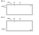
- FIG. 3A and 3B are schematic plan views of the positive electrode member constituting the battery of Example 1.
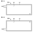
- FIG. 4A and 4B are schematic plan views of the negative electrode member constituting the battery of Example 1.
- FIG. 5A and 5B are schematic plan views of the laminated member. 6A and 6B are schematic diagrams for explaining a bending test performed in Example 1.
- FIG. 7A is a graph showing the results of the bending test of the batteries of Example 1A and Comparative Example 1A
- FIG. 7B is a graph showing the results of measuring complex impedance of the battery of Example 1A
- FIG. 7C is a comparative example. It is a graph which shows the complex impedance measurement result of the battery of 1A.
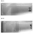
- FIG. 8A is a photograph showing the appearance of the battery of Example 1A after the bending test
- FIG. 8B is a photograph showing the appearance of the battery of Comparative Example 1A after the bending test.
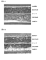
- FIG. 9A is a photograph showing a cross section of the battery of Example 1A before the bending test
- FIG. 9B is a photograph showing a cross section of the battery of Example 1A after the bending test.
- FIG. 9A is a photograph showing a cross section of the battery of Example 1A before the bending test
- FIG. 9B is a photograph showing a cross section of the battery of Example 1A after the bending test.
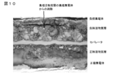
- FIG. 10 is a photograph showing a cross section of the battery of Comparative Example 1A after the bending test.
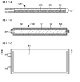
- FIG. 11A, FIG. 11B and FIG. 11C are a schematic cross-sectional view of a laminated member constituting the battery of Example 2, a schematic cross-sectional view of the battery of Example 2, and a schematic of the battery of Example 2. It is a top view.
- FIG. 12A and FIG. 12B are schematic diagrams for explaining a battery bending test method in Example 3, respectively.
- FIG. 13 is a graph showing the evaluation results of the discharge capacity retention rates of the batteries of Example 3A, Example 3B, Reference Example 3D, Reference Example 3E, Comparative Example 3A, Comparative Example 3B, Comparative Example 3D, and Comparative Example 3E. .
- FIG. 14 is a graph showing the evaluation results of the discharge capacity retention rates of the batteries of Example 3A, Example 3C, Reference Example 3D, Reference Example 3F, Comparative Example 3A, Comparative Example 3C, Comparative Example 3D, and Comparative Example 3F. .
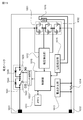
- FIG. 15 is a block diagram illustrating a circuit configuration example of the fourth embodiment in which the battery of the present disclosure described in the first to third embodiments is applied to a battery pack.
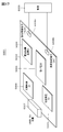
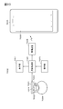
- FIG. 16A, FIG. 16B, and FIG. 16C each represent a block diagram showing a configuration of an application example (electric vehicle) of the present disclosure in the fourth embodiment, and a configuration of an application example (power storage system) of the present disclosure in the fourth embodiment.
- FIG. 17 is a perspective view illustrating an example of a configuration of a printed circuit board as an application example of the present disclosure in the fourth embodiment.
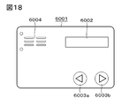
- FIG. 18 is a plan view illustrating an example of the appearance of a universal credit card as an application example of the present disclosure in the fourth embodiment.
- FIG. 19 is a perspective view illustrating an example of an appearance of a wristband type activity meter as an application example of the present disclosure in the fourth embodiment.
- FIG. 20 is a block diagram showing an example of the configuration of the main body of the wristband type activity meter.
- FIG. 21 is a perspective view illustrating an example of an appearance of a wristband type electronic device as an application example of the present disclosure in the fourth embodiment.
- FIG. 22 is a block diagram illustrating an example of a configuration of a wristband type electronic device.
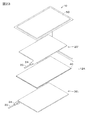
- FIG. 23 is an exploded perspective view of a modified example of the batteries of Examples 1 to 3.
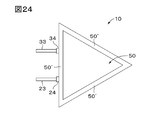
- FIG. 24 is a plan view showing an example of the appearance of a modification of the batteries of Examples 1 to 3.
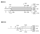
- FIG. 25A and FIG. 25B are a side view showing an example of the configuration of the electrode body of Modification 3 of the battery of the present disclosure, and a side view showing an example of the connection form of the positive electrode lead, respectively.
- the battery according to the first aspect of the present disclosure and the battery according to the first aspect of the present disclosure provided in the electronic device of the present disclosure are collectively referred to as “battery according to the first aspect of the present disclosure”.
- the battery according to the second aspect of the present disclosure and the battery according to the second aspect of the present disclosure provided in the electronic device of the present disclosure are collectively referred to as “battery according to the second aspect of the present disclosure”.
- the battery according to the third aspect of the present disclosure and the battery according to the third aspect of the present disclosure provided in the electronic device of the present disclosure are collectively referred to as “battery according to the third aspect of the present disclosure”.
- battery according to the third aspect of the present disclosure are collectively referred to as “battery according to the third aspect of the present disclosure”.
- the electrolyte may be in the form of a liquid, a gel, or a solid.
- the exterior member is formed from the outside, the resin layer, the intermediate layer And a heat sealing material layer can be laminated.
- the resin layer can include a polyester-based resin, and the resin layer includes a structure including polyethylene terephthalate (PET). can do.
- PET polyethylene terephthalate
- a resin layer can also be set as the structure containing a polyethylene naphthalate (PEN), polyphenylene sulfide, and a polyimide, and can also be comprised from the material with which these various resin was mixed. Further, a resin different from the above can be laminated.
- PEN polyethylene naphthalate
- PEN polyethylene naphthalate
- polyphenylene sulfide polyphenylene sulfide
- a polyimide polyimide
- the resin layer contains at least one of polyethylene terephthalate (PET) and polyethylene naphthalate (PEN), or polyethylene terephthalate and polyethylene It may be composed of a mixture of naphthalates.
- PET polyethylene terephthalate
- PEN polyethylene naphthalate
- “mixing of PET resin and PEN resin” includes not only physical mixing but also chemical reaction (for example, transesterification reaction) between PET resin and PEN resin by heat treatment or melting blending above the melting point. ) are also included.
- the resin layer may contain a resin other than at least one of polyethylene terephthalate and polyethylene naphthalate, but preferably contains at least one of polyethylene terephthalate and polyethylene naphthalate as a main component.
- the main component means that the content of at least one of polyethylene terephthalate and polyethylene naphthalate in the resin layer is 50% by mass or more.
- the resin layer is made of polyethylene terephthalate resin or polyethylene naphthalate resin, these resins have a hardness higher than that of a resin material (eg, polypropylene, PP) used as a resin layer of a general laminate film type battery. Since it is high, the form retainability of the intermediate layer against external force is improved, and even if the battery is repeatedly bent, the intermediate layer is unlikely to crack. Therefore, the sealing performance of the battery is maintained and the intrusion of moisture is suppressed, so that the decrease in the capacity maintenance rate with respect to the charge / discharge cycle is suppressed.
- a resin material eg, polypropylene, PP
- the thickness of the resin layer is more than 40 ⁇ m, preferably 45 ⁇ m or more, more preferably 50 ⁇ m or more.
- the thickness of the resin layer exceeds 40 ⁇ m, even if the battery is repeatedly bent, cracks are unlikely to occur in the intermediate layer, the sealing performance of the battery is maintained, and moisture ingress is suppressed. A decrease in capacity maintenance rate is suppressed.
- the upper limit of the thickness of the resin layer 200 ⁇ m, preferably 150 ⁇ m, more preferably 100 ⁇ m can be mentioned. If the upper limit value of the thickness of the resin layer exceeds 200 ⁇ m, the battery may be too thick, and the function of protecting the surface of the exterior member is sufficient without increasing the thickness of the resin layer to more than 200 ⁇ m. can get.
- the thickness of the resin layer can be measured based on the following method. That is, first, a cross section of the exterior member is cut out by FIB (Focused Ion Beam) processing or the like. Then, this cross section is observed with a scanning electron microscope (SEM), and the thickness of the resin layer included in the exterior member may be obtained.
- FIB Fluorine Beam
- the resin layer in the battery or the like according to the first to third aspects of the present disclosure may be a uniaxially stretched film or a biaxially stretched film.
- the intermediate layer is made of aluminum, aluminum alloy, stainless steel, copper, copper alloy, nickel, or nickel alloy. Of these, aluminum or an aluminum alloy is preferable.
- the stacked members may be connected in parallel in the stacked structure.
- an adhesive layer (for convenience, the “first adhesive” is provided between the resin layer and the intermediate layer. May be provided), or a second pressure-sensitive adhesive layer may be provided between the intermediate layer and the heat sealing material layer.
- the first pressure-sensitive adhesive layer and the second pressure-sensitive adhesive layer are made of, for example, an acrylic pressure-sensitive adhesive, a polyester-based pressure-sensitive adhesive, or a polyurethane-based pressure-sensitive adhesive.
- the 1st adhesive layer may be provided over the whole between a resin layer and an intermediate
- the adhesive layer may be provided with a space portion in the thickness direction.
- the space portions are distributed over the entire area between the resin layer and the intermediate layer, and may be provided in a regular pattern or may be provided randomly.
- the planar shape of the space include, but are not limited to, a mesh shape, a lattice shape, a stripe shape, an island shape, a concentric shape, a spiral shape, a radial shape, a spot shape, a geometric pattern shape, and an indefinite shape. Is not to be done. The same applies to the second pressure-sensitive adhesive layer.
- the exterior member may further include a colored layer on the outer side of the intermediate layer from the viewpoint of the appearance and the like, or at least one of the resin layer, the first pressure-sensitive adhesive layer, and the intermediate layer is colored. Materials may be included.
- the colored layer and the colored material may have a predetermined design.
- a plurality of laminated members are stacked such that current collectors of the same polarity face each other. Insert a film deposited with SiO x or Al 2 O 3 between the second surfaces of the opposing current collectors, or arrange SiO x or Al 2 O 3 fine particles (lubricant). The second surfaces of the opposing current collectors may be relatively easily moved (slid) relative to each other.
- a plurality of laminated members are stacked so that the same-polarity collectors face each other.
- a laminated structure can also be used.
- the exterior member covers a laminated structure in which a plurality of laminated members in which a positive electrode mixture layer and a negative electrode mixture layer are arranged to face each other are stacked so that current collectors of the same polarity face each other. It can also be set as a form. In this case, the laminated members can be connected in parallel in the laminated structure.
- the thickness of the battery is 1 mm or less, preferably 0.7 mm or less, more preferably 0.5 mm or less.
- the thickness of the battery is 1 mm or less, when the battery is bent, a difference in circumferential length between both surfaces of the battery can be suppressed, and generation of wrinkles or the like in the exterior member can be reliably suppressed. . If wrinkles are generated in the exterior member, the exterior member may be destroyed, the electrode may be peeled off, or the appearance may be deteriorated.
- the exterior member is a laminate film in which a resin layer (surface protective layer), an intermediate layer (moisture-proof layer, barrier layer), and a heat seal material layer (melted layer, molten layer) are laminated from the outside.
- a resin layer surface protective layer
- an intermediate layer moisture-proof layer, barrier layer
- a heat seal material layer melted layer, molten layer
- a heat-seal material layer can be comprised from the film of olefin resins, such as polyethylene, a polypropylene, modified polyethylene, a modified polypropylene, and these polymers, for example.
- the resin layer and the intermediate layer, and the intermediate layer and the heat sealing material layer may be bonded to each other using an adhesive.
- the shape of the battery or the like of the present disclosure may include a flat plate shape and a sheet shape.
- the sheet shape includes a curved state. That is, a battery that is originally curved is also included.
- the outer shape of the battery or the like of the present disclosure includes not only a rectangle but also an indefinite shape, and can be an arbitrary outer shape.
- the separator separates the positive electrode member and the negative electrode member, and allows ions to pass while preventing a short circuit of current due to contact between the positive electrode member and the negative electrode member.
- the separator is, for example, polyolefin resin (polypropylene resin or polyethylene resin), acrylic resin, styrene resin, polyester resin, nylon resin, polyimide resin, polytetrafluoroethylene resin, polyvinylidene fluoride resin, polyphenylene sulfide resin, aromatic polyamide, etc.
- a separator can also be comprised from the laminated film in which two or more types of porous films were laminated
- a porous film made of a polyolefin-based resin is preferable because it has an excellent short-circuit prevention effect and can improve battery safety due to a shutdown effect.
- Polyethylene resin is particularly preferable as a material constituting the separator because it can provide a shutdown effect within a range of 100 ° C. or higher and 160 ° C. or lower and is excellent in electrochemical stability.
- the porous film may have, for example, a structure of three or more layers in which a polypropylene resin layer, a polyethylene resin layer, and a polypropylene resin layer are sequentially laminated.
- the thickness of the separator is preferably 5 ⁇ m or more and 50 ⁇ m or less, and more preferably 7 ⁇ m or more and 30 ⁇ m or less. If the separator is too thick, the amount of the active material filled decreases, the battery capacity decreases, and the ionic conductivity decreases and the current characteristics deteriorate. Conversely, when too thin, the mechanical strength of a separator will fall.
- the separator can be made of a base material and a surface layer formed on the surface of the base material, and the surface layer can be made of inorganic particles and a resin material. That is, the separator may have a structure in which a surface layer is provided on one side or both sides of the substrate. Examples of the surface layer include a porous matrix surface layer on which an inorganic substance is supported. That is, the surface layer includes inorganic particles having electrical insulation and a resin material that supports the inorganic particles on the surface of the substrate.
- the resin material may be, for example, fibrillated and have a three-dimensional network structure in which the fibrils are continuously connected to each other.
- the inorganic particles can be maintained in a dispersed state without being in contact with each other by being supported on the resin material having the three-dimensional network structure.
- the resin material may not be fibrillated.
- the substrate is made of a porous material having porosity. That is, the base material is more specifically a porous film composed of an insulating film having a large ion permeability and a predetermined mechanical strength, and the electrolyte is held in the pores of the base material.
- the base material has a predetermined mechanical strength as a main part of the separator, it is preferable that the base material has characteristics such as high resistance to an electrolytic solution, low reactivity, and difficulty in swelling.
- a polyolefin resin such as polypropylene resin or polyethylene resin, an acrylic resin, a styrene resin, a polyester resin, or a nylon resin is preferably used as the resin material constituting the substrate.
- polyethylene such as low density polyethylene, high density polyethylene, linear polyethylene, etc., or these low molecular weight wax components, or polyolefin resins such as polypropylene are suitable for use because they have an appropriate melting temperature and are easily available. It is done.
- a porous membrane made of a polyolefin-based resin is excellent in separability between the positive electrode member and the negative electrode member, and can further reduce the decrease in internal short circuit.
- a nonwoven fabric may be used as the substrate.
- fibers constituting the nonwoven fabric aramid fibers, glass fibers, polyolefin fibers, polyethylene terephthalate (PET) fibers, nylon fibers, and the like can be used. Moreover, it is good also as a nonwoven fabric by mixing these 2 or more types of fibers.
- examples of the material constituting the matrix surface layer include polyvinylidene fluoride (PVdF), hexafluoropropylene (HFP), and polytetrafluoroethylene (PTFE), and these copolymers are used. It is also possible.
- PVdF polyvinylidene fluoride
- HFP hexafluoropropylene
- PTFE polytetrafluoroethylene
- examples of the inorganic particles include metals, semiconductors, and oxides, nitrides, carbides, and sulfides thereof.
- examples of the metal include aluminum (Al) and titanium (Ti)
- examples of the semiconductor include silicon (Si) and boron (B).
- the inorganic particles are preferably substantially non-conductive and have a large heat capacity. When the heat capacity is large, it is useful as a heat sink when heat is generated, and the thermal runaway of the battery can be more effectively suppressed.
- alumina Al 2 O 3
- boehmite alumina monohydrate
- magnesium oxide magnesium oxide
- zirconium oxide zirconia, ZrO 2
- silicon oxide silicon oxide (silica, SiO 2 ) Yttrium oxide (yttria, Y 2 O 3 ), titanium dioxide (titania, TiO 2 ), talc, boron nitride (BN), aluminum nitride (AlN), silicon nitride (Si 3 N 4 ), titanium nitride (TiN), Oxides such as silicon carbide (SiC), boron carbide (B 4 C), and barium sulfate (BaSO 4 ), nitrides, carbides, and sulfides can be given.
- boron nitride aluminum nitride
- Si 3 N 4 silicon nitride
- TiN titanium nitride
- Oxides such as silicon carbide (SiC), boron carbide (B 4
- zeolite M 2 / n O ⁇ Al 2 O 3 ⁇ xSiO 2 ⁇ yH 2 O, M represents a metal element, x ⁇ 2, y ⁇ 0 ) porous aluminosilicates such as layered silicates, titanates Minerals such as barium (BaTiO 3 ) or strontium titanate (SrTiO 3 ) can also be used.
- alumina titania (particularly those having a rutile structure), silica or magnesia, and more preferably alumina.
- the inorganic particles have oxidation resistance and heat resistance, and the surface layer containing the inorganic particles facing the positive electrode member has strong resistance to an oxidizing environment in the vicinity of the positive electrode member during charging.
- the shape of the inorganic particles is not particularly limited, and may be any of a spherical shape, a plate shape, a fiber shape, a cubic shape, a random shape, and the like.
- Examples of the particle diameter of the inorganic particles include 1 nm to 10 ⁇ m. If it is smaller than 1 nm, it is difficult to obtain, and even if it can be obtained, it is not worth the cost.
- Inorganic particles may be contained in a porous membrane as a substrate.
- a slurry composed of a matrix resin, a solvent, and inorganic particles is applied onto a substrate (porous membrane), and is passed through a poor solvent of the matrix resin and a solvent-solvent bath of the solvent to cause phase separation. Then, it can be obtained by drying.
- fluorine-containing resins such as polyvinylidene fluoride and polytetrafluoroethylene
- fluorine-containing rubbers such as vinylidene fluoride-tetrafluoroethylene copolymer and ethylene-tetrafluoroethylene copolymer
- styrene Butadiene copolymer or its hydride acrylonitrile-butadiene copolymer or its hydride, acrylonitrile-butadiene-styrene copolymer or its hydride, methacrylic acid ester-acrylic acid ester copolymer, styrene-acrylic acid ester copolymer
- Polymers acrylonitrile-acrylic acid ester copolymers
- rubbers such as ethylene propylene rubber, polyvinyl alcohol, polyvinyl acetate, ethyl cellulose, methyl cellulose, hydroxyethyl cellulose, carboxymethyl cellulose Cellu
- resin materials may be used alone or in combination of two or more.
- fluorine resins such as polyvinylidene fluoride are preferable from the viewpoint of oxidation resistance and flexibility, and aramid or polyamideimide is preferably included from the viewpoint of heat resistance.
- the inorganic particles may be contained in a porous film as a base material.
- the surface layer may be composed only of a resin material without containing inorganic particles.
- the positive electrode member and the base material are bonded via a surface layer provided on one surface of the base material, and the negative electrode member and the base material are bonded via a surface layer provided on the other surface of the base material. It can be set as a form. That is, a part of the polymer compound contained in the surface layer diffuses into the positive electrode mixture layer and the negative electrode mixture layer, and the separator, the positive electrode member, and the negative electrode member can be integrated. Alternatively, a part of the base material and a part of the positive electrode member are bonded, and a part of the base material and a part of the negative electrode member are bonded.
- the adhesive force between the positive electrode member and the negative electrode member can be increased, and even when the battery is repeatedly bent, the occurrence of peeling between the positive electrode member and the negative electrode member can be suppressed, A decrease in cycle characteristics when the battery is repeatedly bent can be suppressed.
- the piercing strength of the separator 100 gf to 1 kgf, preferably 100 gf to 480 gf can be mentioned. If the piercing strength is low, a short circuit may occur, and if it is high, the ionic conductivity may be reduced. Examples of the air permeability of the separator include 30 seconds / 100 cc to 1000 seconds / 100 cc, preferably 30 seconds / 100 cc to 680 seconds / 100 cc. If the air permeability is too low, a short circuit may occur, and if it is too high, the ion conductivity may decrease.
- the electrolyte may include inorganic particles.
- examples of the inorganic particles include inorganic particles constituting the surface layer.
- the positive electrode current collector for example, copper (Cu), aluminum (Al), nickel (Ni), magnesium (Mg), titanium (Ti), iron (Fe), cobalt (Co), zinc (Zn), germanium (Ge), indium (In), gold (Au), platinum (Pt), silver (Ag), palladium (Pd), etc., or alloys containing any of these Examples thereof include conductive materials such as stainless steel.
- a positive electrode lead portion can be attached to the positive electrode current collector.
- the negative electrode current collector for example, copper (Cu), aluminum (Al), nickel (Ni), magnesium (Mg), titanium (Ti), iron (Fe), cobalt (Co), zinc (Zn) ), Germanium (Ge), indium (In), gold (Au), platinum (Pt), silver (Ag), palladium (Pd), etc., or an alloy containing any of these, or a conductive material such as stainless steel Can be illustrated.
- a negative electrode lead portion can be attached to the negative electrode current collector.
- Examples of the form of the positive electrode current collector or the negative electrode current collector include a foil-like material, a nonwoven fabric-like material, a mesh-like material, and a porous sheet-like material.
- the surface of the negative electrode current collector is preferably roughened from the viewpoint of improving the adhesion of the negative electrode mixture layer to the negative electrode current collector based on the so-called anchor effect.
- at least the surface of the region of the negative electrode current collector on which the negative electrode mixture layer is to be formed should be roughened.
- a roughening method for example, a method of forming fine particles using electrolytic treatment can be mentioned.
- the electrolytic treatment is a method of providing irregularities on the surface of the negative electrode current collector by forming fine particles on the surface of the negative electrode current collector using an electrolysis method in an electrolytic cell.
- the positive electrode lead portion can be attached to the positive electrode current collector based on spot welding or ultrasonic welding.
- the positive electrode lead portion is preferably a metal foil or a mesh-like one, but may not be a metal as long as it is electrochemically and chemically stable and can conduct electricity.
- Examples of the material of the positive electrode lead portion include aluminum (Al), nickel (Ni), stainless steel (SUS), and the like.
- the negative electrode lead portion can also be attached to the negative electrode current collector based on spot welding or ultrasonic welding.
- the negative electrode lead portion is also preferably a metal foil or a mesh-like one, but may not be a metal as long as it is electrochemically and chemically stable and can conduct electricity. Examples of the material for the negative electrode lead portion include copper (Cu) and nickel (Ni).
- the positive electrode lead portion and the negative electrode lead portion can also be constituted by a protruding portion in which a part of the positive electrode current collector or the negative electrode current collector protrudes from the positive electrode current collector or the
- a close-contact film may be inserted.
- the adhesion film can be made of a material having adhesion to the positive electrode lead portion and the negative electrode lead portion, for example, a polyolefin-based resin such as polyethylene, polypropylene, modified polyethylene, or modified polypropylene.
- the positive electrode mixture layer contains a positive electrode active material.
- the positive electrode mixture layer may further contain a positive electrode binder, a positive electrode conductive agent, and the like.
- the negative electrode mixture layer contains a negative electrode active material.
- the negative electrode mixture layer may further contain a negative electrode binder, a negative electrode conductive agent, and the like.
- Examples of the battery of the present disclosure include a lithium ion secondary battery, but the present invention is not limited thereto.
- a magnesium ion battery a negative electrode member containing a negative electrode active material including a metal and an alloy material is included.
- Metal-air secondary batteries metal and alloy materials that can be used for the negative electrode active material include, for example, tin, silicon; alkali metals such as lithium, sodium and potassium; group 2 elements such as magnesium and calcium; Group 13 elements; transition metals such as zinc and iron; or alloy materials and compounds containing these metals), lithium-sulfur secondary batteries, sodium-sulfur secondary batteries, sodium-nickel chloride Secondary battery, sodium ion secondary battery, multivalent cation secondary battery, various organic secondary batteries, nickel-hydrogen secondary battery It can also be mentioned.
- the electrolyte includes a non-aqueous electrolyte and a polymer compound (for example, a resin material) that holds the non-aqueous electrolyte, and the polymer compound is swollen by the non-aqueous electrolyte.
- the content ratio of the holding polymer compound can be appropriately adjusted.
- the polymer compound swollen by the non-aqueous electrolyte may be in the form of a gel or a solid.
- a gel-like or solid electrolyte is preferable because high ion conductivity (for example, 1 mS / cm or more at room temperature) can be obtained and leakage of the electrolyte from the secondary battery 10 can be suppressed.
- the non-aqueous electrolyte contains a non-aqueous solvent and an electrolyte salt.
- the non-aqueous electrolyte solution may further contain a known additive.
- the constituent elements when the battery of the present disclosure including the preferred embodiments and configurations described above are lithium ion batteries that can obtain the capacity of the negative electrode member by occlusion / release of lithium as an electrode reactant will be described below.
- a lithium ion battery at the time of charging, for example, lithium ions are released from the positive electrode active material and occluded in the negative electrode active material via the nonaqueous electrolytic solution.
- lithium ions are released from the negative electrode active material and inserted into the positive electrode active material via the non-aqueous electrolyte solution.
- the positive electrode active material includes, for example, a positive electrode active material that can occlude and release, for example, lithium (Li) ions that are electrode reactants.
- the positive electrode active material capable of inserting and extracting lithium ions include lithium-containing compounds such as lithium-containing composite oxides, lithium-containing phosphate compounds, lithium-containing sulfides, and intercalation compounds containing lithium. Two or more of these may be mixed and used.
- a lithium-containing compound compound containing a lithium atom
- the lithium-containing composite oxide is an oxide containing lithium and one or more elements (hereinafter referred to as “other elements”, excluding lithium) as constituent elements, and has a layered rock salt type crystal structure or It has a spinel crystal structure.
- other elements include a lithium-cobalt material, a lithium-nickel material, a spinel manganese material, and a superlattice structure material.
- the lithium-containing phosphate compound is a phosphate compound containing lithium and one or more elements (other elements) as constituent elements, and has an olivine type crystal structure.
- a lithium-containing compound containing lithium, a transition metal element, and oxygen (O) is preferable for increasing the energy density.
- lithium-containing compound examples include a lithium composite oxide having a layered rock salt type structure represented by formula (A), a lithium composite phosphate having an olivine type structure represented by formula (B), and the like. it can. It is more preferable that the transition metal element in the lithium-containing compound includes at least one selected from the group consisting of cobalt (Co), nickel (Ni), manganese (Mn), and iron (Fe). Examples of such a lithium-containing compound include a lithium composite oxide having a layered rock-salt structure represented by the formula (C), formula (D), or formula (E), and a spinel structure represented by the formula (F). A lithium composite oxide, a lithium composite phosphate having an olivine structure represented by the formula (G), and the like can be given.
- lithium-containing composite oxide having a layered rock salt type crystal structure specifically, LiNiO 2 , LiCoO 2 , LiCo 0.98 Al 0.01 Mg 0.01 O 2 , LiNi 0.5 Co 0.2 Mn 0.3 O 2 , LiNi 0.8 Co 0.15 Al 0.05 O 2 , LiNi 0.33 Co 0.33 Mn 0.33 O 2 , Li c1 Ni c2 Co 1-c2 O 2 (c1 ⁇ 1,0, ⁇ c2 ⁇ 1), Li 1.2 Mn 0.52 Co 0.175 Ni 0.1 O 2 , Li 1.15 Examples include (Mn 0.65 Ni 0.22 Co 0.13 ) O 2 , Li d Mn 2 O 4 (d ⁇ 1), Li e FePO 4 (e ⁇ 1), and the like.
- M 1 represents at least one element selected from Groups 2 to 15 excluding nickel (Ni) and manganese (Mn).
- X represents at least one of group 16 elements and group 17 elements other than oxygen (O).
- p, q, y, and z are 0 ⁇ p ⁇ 1.5, 0 ⁇ q ⁇ 1.0, 0 ⁇ r ⁇ 1.0, ⁇ 0.10 ⁇ y ⁇ 0.20, and 0 ⁇ z. It is a value within the range of ⁇ 0.2.
- M 2 represents at least one element selected from Group 2 to Group 15.
- a and b are 0 ⁇ a ⁇ 2.0 0.5 ⁇ b ⁇ 2.0 It is a value within the range.
- M 3 is cobalt (Co), magnesium (Mg), aluminum (Al), boron (B), titanium (Ti), vanadium (V), chromium (Cr), iron (Fe ), Copper (Cu), zinc (Zn), zirconium (Zr), molybdenum (Mo), tin (Sn), calcium (Ca), strontium (Sr) and tungsten (W). Represents a kind of element.
- F, g, h, j and k are 0.8 ⁇ f ⁇ 1.2 0 ⁇ g ⁇ 0.5 0 ⁇ h ⁇ 0.5 (G + h) ⁇ 1 ⁇ 0.1 ⁇ j ⁇ 0.2 0 ⁇ k ⁇ 0.1 It is a value within the range.
- the composition shown in the formula (C) varies depending on the state of charge and discharge, and the value of f represents a value in a complete discharge state.
- M 4 is cobalt (Co), manganese (Mn), magnesium (Mg), aluminum (Al), boron (B), titanium (Ti), vanadium (V), chromium (Cr ), Iron (Fe), copper (Cu), zinc (Zn), molybdenum (Mo), tin (Sn), calcium (Ca), strontium (Sr) and tungsten (W).
- M, n, p and q are 0.8 ⁇ m ⁇ 1.2 0.005 ⁇ n ⁇ 0.5 ⁇ 0.1 ⁇ p ⁇ 0.2 0 ⁇ q ⁇ 0.1 It is a value within the range.
- the composition shown in the formula (D) varies depending on the state of charge and discharge, and the value of m represents a value in a complete discharge state.
- M 5 is nickel (Ni), manganese (Mn), magnesium (Mg), aluminum (Al), boron (B), titanium (Ti), vanadium (V), chromium (Cr ), Iron (Fe), copper (Cu), zinc (Zn), molybdenum (Mo), tin (Sn), calcium (Ca), strontium (Sr) and tungsten (W).
- r, s, t and u are 0.8 ⁇ r ⁇ 1.2 0 ⁇ s ⁇ 0.5 ⁇ 0.1 ⁇ t ⁇ 0.2 0 ⁇ u ⁇ 0.1 It is a value within the range.
- the composition shown in the formula (E) varies depending on the state of charge / discharge, and the value of r represents a value in a complete discharge state.
- M 6 is cobalt (Co), nickel (Ni), magnesium (Mg), aluminum (Al), boron (B), titanium (Ti), vanadium (V), chromium (Cr ), Iron (Fe), copper (Cu), zinc (Zn), molybdenum (Mo), tin (Sn), calcium (Ca), strontium (Sr) and tungsten (W).
- V, w, x and y are 0.9 ⁇ v ⁇ 1.1 0 ⁇ w ⁇ 0.6 3.7 ⁇ x ⁇ 4.1 0 ⁇ y ⁇ 0.1 It is a value within the range.
- the composition shown in Formula (F) varies depending on the state of charge and discharge, and the value of v represents a value in a fully discharged state.
- M 7 is cobalt (Co), manganese (Mn), iron (Fe), nickel (Ni), magnesium (Mg), aluminum (Al), boron (B), titanium (Ti ), Vanadium (V), niobium (Nb), copper (Cu), zinc (Zn), molybdenum (Mo), calcium (Ca), strontium (Sr), tungsten (W) and zirconium (Zr).
- Z is 0.9 ⁇ z ⁇ 1.1 It is a value within the range.
- the composition shown in the formula (G) varies depending on the state of charge / discharge, and the value of z represents a value in a complete discharge state.
- positive electrode active materials capable of inserting and extracting lithium include inorganic compounds not containing lithium, such as MnO 2 , V 2 O 5 , V 6 O 13 , NiS, and MoS. However, it may be other than the above. Moreover, you may mix 2 or more types of positive electrode active materials illustrated above by arbitrary combinations.
- Examples of the negative electrode active material include carbon materials. Since the carbon material has very little change in crystal structure during insertion and extraction of lithium, a high energy density can be stably obtained. In addition, since the carbon material also functions as a negative electrode conductive agent, the conductivity of the negative electrode mixture layer is improved. Examples of the carbon material include graphitizable carbon (soft carbon), non-graphitizable carbon (hard carbon), graphite (graphite), and a highly crystalline carbon material having a developed crystal structure. However, the (002) plane spacing in non-graphitizable carbon is preferably 0.37 nm or more, and the (002) plane spacing in graphite is preferably 0.34 nm or less.
- the carbon material for example, pyrolytic carbons; cokes such as pitch coke, needle coke, and petroleum coke; graphites; glassy carbon fibers; polymer compounds such as phenol resin and furan resin are suitable.
- Organic polymer compound fired bodies obtainable by firing (carbonization) at temperature; carbon fibers; activated carbon; carbon blacks; polymers such as polyacetylene and polypyrrole.
- graphite include natural graphite subjected to spheroidizing treatment and the like, and substantially spherical artificial graphite.
- the artificial graphite include artificial graphite obtained by graphitizing mesocarbon microbeads (MCMB) and artificial graphite obtained by graphitizing and pulverizing a coke raw material.
- examples of the carbon material may include low crystalline carbon that has been heat-treated at a temperature of about 1000 ° C. or lower, or amorphous carbon.
- the shape of the carbon material may be any of a fibrous shape, a spherical shape, a granular shape, and a scale shape. These carbon materials are preferable because the change in crystal structure that occurs during charge and discharge is very small, a high charge and discharge capacity can be obtained, and good cycle characteristics can be obtained.
- graphite is preferable because it has a high electrochemical equivalent and can provide a high energy density.
- non-graphitizable carbon is preferable because excellent characteristics can be obtained.
- those having a low charge / discharge potential specifically, those having a charge / discharge potential close to that of lithium metal are preferable because a high energy density of the battery can be easily realized.
- the negative electrode active material can include, for example, a material containing one or more metal elements or metalloid elements as constituent elements (hereinafter referred to as “metal-based material”).
- metal-based material may be any of a simple substance, an alloy, and a compound, or may be a material composed of two or more of these, or a material having at least one of these one or two or more phases. It may be.
- the alloy includes a material including one or more metal elements and one or more metalloid elements in addition to a material composed of two or more metal elements.
- the alloy may contain a nonmetallic element.
- Examples of the structure of the metal-based material include a solid solution, a eutectic (eutectic mixture), an intermetallic compound, and two or more kinds of these coexisting substances.
- a high energy density can be obtained.
- it is more preferable to use the carbon material together with the carbon material because a higher energy density can be obtained and cycle characteristics can be improved.
- metal elements and metalloid elements include metal elements and metalloid elements that can form an alloy with lithium.
- silicon (Si) and tin (Sn) are preferable from the viewpoint that they have an excellent ability to occlude and release lithium, and a significantly high energy density can be obtained.
- These materials may be crystalline or amorphous.
- the negative electrode material is preferably one containing a 4B group metal element or a semimetal element in the short-period type periodic table as a constituent element, and particularly preferably at least one of silicon (Si) and tin (Sn) as a constituent element. Is included. This is because silicon (Si) and tin (Sn) have a large ability to occlude and release lithium (Li), and a high energy density can be obtained.
- Examples of the material containing silicon as a constituent element include a simple substance of silicon, a silicon alloy, and a silicon compound. The material may be composed of two or more of these, or one or more of these. A material having at least a part of the above phase may be used.
- Examples of the material containing tin as a constituent element include a simple substance of tin, a tin alloy, and a tin compound. The material may be composed of two or more of these, or one or more of these. A material having at least a part of the above phase may be used.
- the simple substance means a simple substance in a general sense, and may contain a small amount of impurities, and does not necessarily mean 100% purity.
- tin (Sn), nickel (Ni), copper (Cu), iron (Fe), cobalt (Co), manganese (Mn), zinc (Zn), indium (In), silver (Ag), titanium (Ti), germanium (Ge), bismuth (Bi), antimony (Sb), chromium (Cr), carbon (C), oxygen (O) It can also be mentioned.
- silicon alloy or silicon compound examples include SiB 4 , SiB 6 , Mg 2 Si, Ni 2 Si, TiSi 2 , MoSi 2 , CoSi 2 , NiSi 2 , CaSi 2 , CrSi 2 , Cu 5 Si, and FeSi 2.
- Specific examples of the tin alloy or tin compound include SnO w (0 ⁇ w ⁇ 2), SnSiO 3 , LiSnO, and Mg 2 Sn.
- the material containing tin as a constituent element is preferably a material containing a second constituent element and a third constituent element together with tin (first constituent element) (hereinafter referred to as “Sn-containing material”).
- the second constituent element for example, cobalt (Co), iron (Fe), magnesium (Mg), titanium (Ti), vanadium (V), chromium (Cr), manganese (Mn), nickel (Ni), copper ( Cu), zinc (Zn), gallium (Ga), zirconium (Zr), niobium (Nb), molybdenum (Mo), silver (Ag), indium (In), cesium (Ce), hafnium (Hf), tantalum ( Ta), tungsten (W), bismuth (Bi), silicon (Si) can be mentioned, and as the third constituent element, for example, boron (B), carbon (C), aluminum (Al), phosphorus (P) ).
- the Sn-containing material contains the second constituent element and the second
- the Sn-containing material is preferably a material containing tin (Sn), cobalt (Co), and carbon (C) as constituent elements (referred to as “SnCoC-containing material”).
- SnCoC-containing material for example, the carbon content is 9.9 mass% to 29.7 mass%, and the content ratio of tin and cobalt ⁇ Co / (Sn + Co) ⁇ is 20 mass% to 70 mass%. It is. This is because a high energy density can be obtained.
- the SnCoC-containing material has a phase containing tin, cobalt, and carbon, and the phase is preferably low crystalline or amorphous.
- This phase is a reaction phase capable of reacting with lithium, excellent characteristics can be obtained due to the presence of the reaction phase.
- the half width (diffraction angle 2 ⁇ ) of the diffraction peak obtained by X-ray diffraction of this reaction phase is 1 degree or more when CuK ⁇ ray is used as the specific X-ray and the insertion speed is 1 degree / minute. preferable. This is because lithium is occluded and released more smoothly and the reactivity with the non-aqueous electrolyte is reduced.
- the SnCoC-containing material may contain a phase containing a simple substance or a part of each constituent element in addition to a low crystalline or amorphous phase.
- Such a reaction phase contains, for example, each of the above-described constituent elements, and is considered to be low crystallized or amorphous mainly due to the presence of carbon.
- the SnCoC-containing material it is preferable that at least a part of carbon as a constituent element is bonded to a metal element or a metalloid element. This is because aggregation and crystallization of tin and the like are suppressed.
- the bonding state of the elements can be confirmed using, for example, X-ray photoelectron spectroscopy (XPS) using Al—K ⁇ ray or Mg—K ⁇ ray as a soft X-ray source.
- XPS X-ray photoelectron spectroscopy
- the energy is calibrated so that the peak of the gold atom 4f orbit (Au4f) is obtained at 84.0 eV.
- the C1s peak of the surface-contaminated carbon is set to 284.8 eV, and the peak is used as an energy reference.
- the waveform of the C1s peak is obtained in a form including the surface contamination carbon peak and the carbon peak in the SnCoC-containing material. Therefore, for example, analysis may be performed using commercially available software, and both peaks may be separated. In the waveform analysis, the position of the main peak existing on the lowest bound energy side is used as the energy reference (284.8 eV).
- the SnCoC-containing material is not limited to a material (SnCoC) whose constituent elements are only tin, cobalt, and carbon.
- SnCoC-containing material include, in addition to tin, cobalt and carbon, silicon (Si), iron (Fe), nickel (Ni), chromium (Cr), indium (In), niobium (Nb), and germanium (Ge).
- Titanium (Ti), molybdenum (Mo), aluminum (Al), phosphorus (P), gallium (Ga), bismuth (Bi) or the like may be included as a constituent element.
- SnCoFeC-containing materials materials containing tin, cobalt, iron and carbon as constituent elements
- the composition of the SnCoFeC-containing material is arbitrary.
- the iron content is set to be small
- the carbon content is 9.9 mass% to 29.7 mass%
- the iron content is 0.3 mass% to 5.9 mass%
- the ratio of content of tin and cobalt ⁇ Co / (Sn + Co) ⁇ is 30% by mass to 70% by mass.
- the carbon content is 11.9% to 29.7% by mass, and the ratio of tin, cobalt, and iron content ⁇ (Co + Fe) / (Sn + Co + Fe) ⁇ 26.4% by mass to 48.5% by mass, and the ratio of content of cobalt and iron ⁇ Co / (Co + Fe) ⁇ is 9.9% by mass to 79.5% by mass.
- the physical properties (half width, etc.) of the SnCoFeC-containing material are the same as the physical properties of the above-described SnCoC-containing material.
- negative electrode active materials for example, iron oxide, ruthenium oxide, molybdenum oxide, manganese dioxide (MnO 2 ), vanadium oxide (V 2 O 5 , V 6 O 13 ) and other metal oxides, nickel sulfide (NiS) ), Sulfides such as molybdenum sulfide (MoS), lithium nitrides such as LiN 3 , and polymer compounds such as polyacetylene, polyaniline, and polypyrrole.
- the negative electrode active material preferably contains both a carbon material and a metal-based material for the following reasons. That is, a metal material, particularly a material containing at least one of silicon and tin as a constituent element has an advantage of high theoretical capacity, but easily expands and contracts violently during charge and discharge.
- the carbon material has an advantage that the theoretical capacity is low, but it is difficult to expand and contract during charging and discharging. Therefore, by using both the carbon material and the metal-based material, expansion / contraction during charging / discharging is suppressed while obtaining a high theoretical capacity (in other words, battery capacity).
- the positive electrode binder and the negative electrode binder include styrene butadiene rubber such as styrene butadiene rubber (SBR), fluorine rubber, and synthetic rubber such as ethylene propylene diene; polyvinylidene fluoride (PVdF), polyvinyl fluoride, Fluorine resins such as polyimide, polytetrafluoroethylene (PTFE) and ethylenetetrafluoroethylene (ETFE), copolymers and modified products of these fluorine resins; polyolefin resins such as polyethylene and polypropylene; polyacrylonitrile (PAN) and Acrylic resins such as polyacrylic acid esters; polymer materials such as carboxymethyl cellulose (CMC) can be exemplified, and at least one selected from copolymers mainly composed of these resin materials It can be.
- SBR styrene butadiene rubber
- PVdF polyvinylidene fluoride
- PTFE polytetra
- polyvinylidene fluoride-hexafluoropropylene copolymer for example, polyvinylidene fluoride-hexafluoropropylene copolymer, polyvinylidene fluoride-tetrafluoroethylene copolymer, polyvinylidene fluoride-chlorotrifluoroethylene copolymer
- a conductive polymer for example, substituted or unsubstituted polyaniline, polypyrrole, polythiophene, and one or two (co) polymers selected from these can be used.
- Examples of the positive electrode conductive agent and the negative electrode conductive agent include graphite, carbon fiber, carbon black, carbon nanotube, graphite, vapor-grown carbon fiber (Vapor Growth Carbon Fiber: VGCF), acetylene black (AB), and ketjen black (KB). Carbon materials such as these can be used, and one or more of these can be used in combination.
- Examples of carbon nanotubes include multi-wall carbon nanotubes (MWCNT) such as single wall carbon nanotubes (SWCNT) and double wall carbon nanotubes (DWCNT).
- MWCNT multi-wall carbon nanotubes
- SWCNT single wall carbon nanotubes
- DWCNT double wall carbon nanotubes
- a metal material, a conductive polymer material, or the like may be used as long as the material has conductivity.
- the positive electrode mixture layer and the negative electrode mixture layer can be formed based on, for example, a coating method. That is, a particle (powder) positive electrode active material or a negative electrode active material is mixed with a positive electrode binder, a negative electrode binder, or the like, and then the mixture is dispersed in a solvent such as an organic solvent to obtain a positive electrode current collector or a negative electrode current collector. It can be formed based on a method of applying to the body (for example, an application method using a spray). However, the coating method is not limited to such a method, and is not limited to the coating method. For example, a negative electrode member can be obtained by molding a negative electrode active material, and a positive electrode active material. A positive electrode member can be obtained by molding.
- a press machine may be used for molding.
- it can be formed based on a vapor phase method, a liquid phase method, a thermal spraying method, or a firing method (sintering method).
- the vapor phase method is a PVD method (physical vapor deposition method) such as a vacuum deposition method, a sputtering method, an ion plating method or a laser ablation method, or various CVD methods (chemical vapor deposition methods) including a plasma CVD method.
- the liquid phase method include an electrolytic plating method and an electroless plating method.
- the thermal spraying method is a method in which a molten or semi-molten positive electrode active material or negative electrode active material is sprayed onto a positive electrode current collector or a negative electrode current collector.
- the firing method is, for example, a method in which a mixture dispersed in a solvent using a coating method is applied to the negative electrode current collector and then heat-treated at a temperature higher than the melting point of the negative electrode binder, etc. Examples thereof include a reactive firing method and a hot press firing method.
- the chargeable capacity of the negative electrode member is preferably larger than the discharge capacity of the positive electrode member. That is, the electrochemical equivalent of the negative electrode member capable of inserting and extracting lithium is preferably larger than the electrochemical equivalent of the positive electrode member.
- the lithium deposited on the negative electrode member is, for example, lithium metal when the electrode reactant is lithium.
- the electrolyte salt contains one or more lithium salts.
- the lithium salt that constitutes the non-aqueous electrolyte suitable for use in a lithium ion secondary battery for example, LiPF 6, LiClO 4, LiBF 4, LiAsF 6, LiSbF 6, LiTaF 6, LiNbF 6, LiAlCl 4, LiSiF 6, LiCF 3 SO 3 , LiN (SO 2 CF 3 ) 2 , LiN (CnF 2n + 1 SO 2 ) 2 , LiC (SO 2 CF 3 ) 3 , LiB (C 6 H 5 ) 4 , LiCH 3 SO 3 , LiN ( CF 3 SO 2 ) 2 , LiC (CF 3 SO 2 ) 3 , LiC 4 F 9 SO 3 , Li (FSO 2 ) 2 N (aka “LiFSI”), Li (CF 3 SO 2 ) 2 N, Li (C 2 F 5 SO 2 ) 2 N, Li (CF 3 SO 2 ) 3 C, LiBF 3 (C 2 F 5
- cyclic carbonates such as ethylene carbonate (EC), propylene carbonate (PC), and butylene carbonate (BC) can be used as the organic solvent (non-aqueous solvent).
- ethylene carbonate (EC) or propylene carbonate (PC) it is preferable to use ethylene carbonate (EC) or propylene carbonate (PC), or it is more preferable to use a mixture of both, thereby improving the cycle characteristics.
- these cyclic carbonates may be used in combination with a chain carbonate ester such as diethyl carbonate, dimethyl carbonate, ethyl methyl carbonate, or methyl propyl carbonate. it can.
- the solvent may contain 2,4-difluoroanisole or vinylene carbonate.
- 2,4-Difluoroanisole can improve discharge capacity
- vinylene carbonate can improve cycle characteristics. Therefore, it is preferable to use a mixture of these because the discharge capacity and cycle characteristics can be improved.
- DMC dimethyl carbonate
- EMC ethyl methyl carbonate
- DEC diethyl carbonate
- DPC dipropyl carbonate
- PMC propyl methyl carbonate
- PEC propyl ethyl carbonate
- Chain carbonates such as fluoroethylene carbonate (FEC); tetrahydrofuran (THF), 2-methyltetrahydrofuran (2-MeTHF), 1,3-dioxolane (DOL), 4-methyl-1,3-dioxolane (4- Cyclic ethers such as MeDOL; chain ethers such as 1,2-dimethoxyethane (DME) and 1,2-diethoxyethane (DEE); cyclic esters such as ⁇ -butyrolactone (GBL) and ⁇ -valerolactone (GVL) And chain esters such as methyl acetate, ethyl acetate, propyl
- organic solvent non-aqueous solvent
- tetrahydropyran 1,3-dioxane, 1,4-dioxane
- N N-dimethylformamide
- DMA N-dimethylacetamide
- NMP N-methyl -2-pyrrolidone
- NMO N-methyloxazolidinone
- DI dimethyl sulfoxide
- TMP trimethyl phosphate
- NM nitromethane
- Nitroethane (NE) sulfolane
- AN methyl sulfolane
- acetonitrile AN
- succinonitrile SN
- anisole propionitrile
- glutaronitrile GNN
- ADN methoxyacetonitrile
- MAN 3-methoxypropio Tolyl
- diethyl diethyl
- an ionic liquid can be used.
- a well-known thing can be used as an ionic liquid, and what is necessary is just to select as needed. Among them, if at least two of the groups consisting of fluoroethylene carbonate, ethylene carbonate, propylene carbonate, vinylene carbonate, diethyl carbonate, dimethyl carbonate, and ethyl methyl carbonate are used in combination, excellent charge / discharge capacity characteristics and charge / discharge cycle It is preferable because characteristics can be obtained.
- the holding polymer compound include polyacrylonitrile, polyvinylidene fluoride, polytetrafluoroethylene, polyhexafluoropropylene, polyethylene oxide, polypropylene oxide, polyphosphazene, polysiloxane, polyvinyl fluoride (PVF), poly Chlorotrifluoroethylene (PCTFE), perfluoroalkoxy fluororesin (PFA), tetrafluoroethylene-hexafluoropropylene copolymer (FEP), ethylene-tetrafluoroethylene copolymer (ETFE), ethylene-chlorotrifluoro Ethylene copolymer (ECTFE), polyvinyl acetate, polyvinyl alcohol, polymethyl methacrylate, polyacrylic acid, polymethacrylic acid, styrene-butadiene rubber, nitrile-butadiene rubber, polystyrene, Polycarbonate can be exemplified vinyl chloride.
- the holding polymer compound may be a copolymer.
- the copolymer include a polyvinylidene fluoride-hexafluoropropylene copolymer.
- a homopolymer such as polyvinylidene fluoride, Acrylonitrile, polyhexafluoropropylene, and polyethylene oxide are preferred, and a polyvinylidene fluoride-hexafluoropropylene copolymer is preferred as the copolymer.
- the filler may contain a compound having high heat resistance such as Al 2 O 3 , SiO 2 , TiO 2 , BN (boron nitride).
- the device of the present disclosure includes the battery of the present disclosure described above.
- the wearable device of the present disclosure includes the battery of the present disclosure described above
- the IC card of the present disclosure includes the battery of the present disclosure described above.
- an electronic apparatus (electronic device) of the present disclosure provided with the battery of the present disclosure (specifically, a lithium ion secondary battery), for example, a notebook personal computer, a tablet computer, a personal computer as a detachable power source, etc.
- Battery packs various display devices, PDAs (Personal Digital Assistants, personal digital assistants), remote controllers, mobile phones, smartphones, cordless phone masters and slaves, video movies (video cameras and camcorders), digital still cameras , Electronic papers such as electronic books (electronic books) and electronic newspapers, electronic dictionaries, music players, portable music players, radios, portable radios, headphones, headphone stereos, game consoles, and various detachable structures Wearable devices (for example, smartphones Band-type electronic devices such as wristwatches, wristbands, smart eyeglasses, smartbands, wristwatch-type terminals, bracelet-type electronic devices, eyeglass-type electronic devices such as head-mounted displays, shoe-type electronic devices or clothing-type electronic devices, medical devices, Health care products, etc.), navigation systems, memory cards, IC cards, cardiac pacemakers, hearing aids, toys, robots.
- smartphones Band-type electronic devices such as wristwatches, wristbands, smart eyeglasses, smartbands, wristwatch-type terminals, bracelet-type electronic
- the battery of the present disclosure can be used for an electric tool, an electric shaver, a refrigerator, an air conditioner, a television receiver, a stereo, a water heater, a microwave oven, a dishwasher, a laundry Drives for lighting equipment including dryers, dryers, room lights, etc., various electrical equipment (including portable electronic equipment), road conditioners, traffic lights, railway cars, golf carts, electric carts, electric cars (including hybrid cars), etc. It can be used as a power source or auxiliary power source. Moreover, it can mount in the electric power storage power supply etc. for buildings or electric power generation facilities including a house, or can be used in order to supply electric power to these.
- a converter that converts electric power into driving force by supplying electric power is generally a motor.
- the control device (control unit) that performs information processing related to vehicle control include a control device that displays a remaining battery level based on information about the remaining battery level.
- a battery can also be used in a power storage device in a so-called smart grid.
- Such a power storage device can not only supply power but also store power by receiving power from another power source.
- power sources for example, thermal power generation, nuclear power generation, hydroelectric power generation, solar cells, wind power generation, geothermal power generation, fuel cells (including biofuel cells) and the like can be used.
- the battery of the present disclosure including the above-described various preferable modes and configurations can be applied to a battery and a battery in a battery pack having a control means (control unit) that performs control related to the battery.
- the control means controls, for example, charge / discharge, overdischarge, or overcharge related to the battery.
- the battery of the present disclosure including the above-described various preferable modes and configurations can be applied to a battery in an electronic device that receives power supply from the battery.
- a battery in an electric vehicle having a conversion device that receives power supply from the battery and converts it into a driving force of the vehicle, and a control device (control unit) that performs information processing related to vehicle control based on information related to the battery.
- the battery of the present disclosure including the preferable forms and configurations of the above can be applied.
- the conversion device typically receives power supplied from a battery to drive a motor and generate a driving force. Regenerative energy can also be used to drive the motor.
- a control apparatus (control part) performs the information processing regarding vehicle control based on the battery remaining charge of a battery, for example.
- This electric vehicle includes, for example, an electric vehicle, an electric motorcycle, an electric bicycle, a railway vehicle, and so-called hybrid vehicles.
- the battery of the present disclosure including the above-described various preferable modes and configurations is applied to a battery in a power system configured to receive power supply from the battery and / or to supply power from the power source to the battery. be able to.
- the power system may be any power system as long as it uses power approximately, and includes a simple power device.
- This power system includes, for example, a smart grid, a home energy management system (HEMS), a vehicle, and the like, and can also store electricity.
- HEMS home energy management system
- the battery of the present disclosure including the above-described various preferable modes and configurations can be applied to a battery in a power storage power source configured to have a battery and to be connected to an electronic device to which power is supplied.
- the power storage power source can be used for any power system or power device, regardless of the use of the power storage power source. For example, it can be used for a smart grid.
- Example 1 relates to a battery according to the first aspect of the present disclosure.
- the battery of Example 1 is a lithium ion secondary battery.
- FIG. 1A shows a schematic cross-sectional view of the laminated structure constituting the battery of Example 1
- FIG. 1B shows a schematic cross-sectional view of the laminated member constituting the battery of Example 1
- the battery of Example 1 1C is a schematic sectional view of the battery of Example 1
- FIG. 2 is a schematic exploded perspective view of the battery of Example 1
- FIG. 1D is a schematic plan view of the battery of Example 1.
- 3A and 3B are schematic plan views of the positive electrode member constituting the battery of Example 1
- FIGS. 4A and 4B are schematic plan views of the negative electrode member constituting the battery of Example 1.
- FIG. 1A shows a schematic cross-sectional view of the laminated structure constituting the battery of Example 1
- FIG. 1B shows a schematic cross-sectional view of the laminated member constituting the battery of Example 1
- FIG. 1C A schematic plan view of the laminated member is shown in FIG.
- the schematic cross-sectional view of FIG. 1C is a schematic cross-sectional view along the arrow AA of FIG. 1D.
- FIG. 1A the laminated members are illustrated in a separated state, but actually, the laminated members are in contact with each other. In FIG. 2 and FIG. 23 described later, only one laminated member 12A is shown.
- the battery 10 of Example 1 is A positive electrode member 20 having a positive electrode mixture layer 22 formed on one surface of a positive electrode current collector 21; Separator 40 containing electrolyte, and A negative electrode member 30 formed by forming a negative electrode mixture layer 32 on one surface of the negative electrode current collector 31; Are stacked, and the laminated member 12 in which the positive electrode mixture layer 22 and the negative electrode mixture layer 32 are arranged to face each other includes a plurality of current collectors having the same polarity (the positive electrode current collector 21 and the positive electrode current collector 21, A laminated structure 11 in which the negative electrode current collector 31 and the negative electrode current collector 31) are stacked so as to face each other, and An exterior member 50 for covering (sealing) the laminated structure 11; With The exterior member 50 includes at least a resin layer 51 having a Young's modulus of 3 ⁇ 10 9 Pa or more, preferably 4 ⁇ 10 9 Pa or more.
- the exterior member 50 is formed by laminating a resin layer (surface protective layer) 51, an intermediate layer (moisture-proof layer, barrier layer) 52, and a heat seal material layer (melted layer, molten layer) 53 from the outside.
- the resin layer 51 is made of, for example, a polyester-based resin, specifically, for example, polyethylene terephthalate resin (PET resin).
- PET resin polyethylene terephthalate resin
- the intermediate layer 52 is made of an aluminum foil, and the heat sealing material layer is made of a biaxially oriented polypropylene (CPP) film. Furthermore, in the laminated structure 11, the laminated members 12 are connected in parallel.
- the exterior member 50 includes a first exterior member 50A and a second exterior member 50B, and the first exterior member 50A and the second exterior member 50B have the same size and are laminated.
- the structures 11 are overlapped so as to sandwich the structure 11 therebetween.
- the four sides of the first exterior member 50A and the second exterior member 50B that are overlapped are fused to form a fused portion 50 ′ at the peripheral portions of the first exterior member 50A and the second exterior member 50B. .
- the shape of the battery of Example 1 or the battery of Example 2 to be described later is a flat plate shape or a sheet shape. That is, when the battery 10 of Example 1 is viewed in plan from a direction perpendicular to the main surface, the battery 10 has a rectangular shape.
- the positive electrode current collector 21 is made of an aluminum foil having a thickness of 12 ⁇ m.
- the positive electrode mixture layer 22 is composed of a positive electrode active material made of LiCoO 2 (LCO), a positive electrode conductive agent, and a positive electrode binder (polyvinylidene fluoride-hexafluoropropylene copolymer).
- the negative electrode current collector 31 is made of a copper foil having a thickness of 8 ⁇ m.
- the negative electrode mixture layer 32 is composed of graphite powder, a negative electrode conductive agent, and a negative electrode binder (polyvinylidene fluoride-hexafluoropropylene copolymer).
- the electrolyte salt in the gel electrolyte was composed of LiPF 6 , and a polyvinylidene fluoride-hexafluoropropylene copolymer was used as the holding polymer compound.
- the separator 40 is made of a porous polyethylene film.
- a positive electrode active material made of LiCoO 2 (LCO)
- a positive electrode conductive agent made of carbon black
- a positive electrode binder polyvinylidene fluoride-hexafluoropropylene copolymer
- the slurry was dried and compression-molded with a roll press, and the positive electrode mixture layer 22 and the positive electrode current collector 21 were integrated.
- the positive electrode mixture layer 22 is formed on the entire surface of the positive electrode current collector 21 except for the protruding portion 23 which is a positive electrode lead portion.
- the positive electrode mixture layer 22 is clearly shown.
- the positive electrode mixture layer 22 is drawn inside the positive electrode current collector 21.
- the positive electrode member 20 thus obtained was punched into a bilaterally symmetric mold using a mold to obtain a positive electrode member 20A and a positive electrode member 20B (see FIGS. 3A and 3B).
- the positive electrode current collector 21 is provided with a protruding portion 23 (23A, 23B) as a positive electrode lead portion.
- the protruding portion 23 (23A, 23B) protrudes from the one short side of the battery 10 in the same direction.
- Adhesive films 24 and 34 shown only in FIG. 23) for preventing the entry of outside air may be inserted between the exterior member 50 and the protrusion 23.
- the negative electrode mixture layer 32 is formed on the entire surface of the negative electrode current collector 31 except for the protruding portion 33 that is the negative electrode lead portion.
- the negative electrode mixture layer 32 is clearly shown.
- the negative electrode mixture layer 32 is drawn inside the negative electrode current collector 31.
- the negative electrode member 30 thus obtained was punched into a symmetrical mold to obtain a negative electrode member 30A and a negative electrode member 30B (see FIGS. 4A and 4B).
- the negative electrode current collector 31 is provided with a protruding portion 33 (33A, 33B) as a negative electrode lead portion.
- the electrolyte solution was uniformly applied to the surfaces of the positive electrode mixture layer 22 and the negative electrode mixture layer 32 of the positive electrode member and the negative electrode member, and the positive electrode mixture layer 22 and the negative electrode mixture layer 32 were impregnated. Subsequently, it was left at room temperature for 8 hours, and dimethyl carbonate was vaporized and removed to obtain a gel electrolyte.
- the positive electrode member 20A and the negative electrode member 30A which are manufactured as described above and impregnated with the gel electrolyte, are positioned through the separator 40 made of a porous polyethylene film having a thickness of 10 ⁇ m and the position “A” shown in FIG. After being placed so as to overlap with the position of “C” shown in 4A and temporarily press-bonded, it was heat-pressed by a 105 ° C. press to obtain a laminated member 12A shown in FIG. 5A.
- the positive electrode member 20B and the negative electrode member 30B which are manufactured as described above and impregnated with the gel electrolyte, are passed through the separator 40 made of a porous polyethylene film having a thickness of 10 ⁇ m and the “B” shown in FIG. 3B.
- the position and the position of “D” shown in FIG. 4B are arranged so as to overlap each other and temporarily press-bonded, followed by thermo-compression using a 105 ° C. press to obtain a laminated member 12B shown in FIG. 5B.
- the laminated member 12A, the laminated member 12B, the laminated member 12B, and the laminated member 12A produced as described above are arranged in such a manner that the positive electrode members and the negative electrode members face each other, and the four laminated members are overlapped. .
- the take-out electrode portions (each of the projecting portions 23 and each of the projecting portions 33) of the laminated member were joined with an ultrasonic welding machine to obtain an electrically connected battery (battery before assembly).
- the exterior member in which the heat seal material layer 53 made of was laminated was used. And the battery before an assembly was coat
- Example 1 the battery of Comparative Example 1A was produced instead of the exterior member. Specifically, a resin layer made of stretched nylon (ON) with a thickness of 15 ⁇ m, an intermediate layer made of aluminum foil with a thickness of 30 ⁇ m, and a heat seal material layer made of a biaxially stretched polypropylene (CPP) film with a thickness of 25 ⁇ m are laminated. A battery of Comparative Example 1A was produced using the prepared exterior member.
- a resin layer made of stretched nylon (ON) with a thickness of 15 ⁇ m an intermediate layer made of aluminum foil with a thickness of 30 ⁇ m
- a heat seal material layer made of a biaxially stretched polypropylene (CPP) film with a thickness of 25 ⁇ m are laminated.
- a battery of Comparative Example 1A was produced using the prepared exterior member.
- Comparative Example 1B a battery in which the electrolyte was not a gel but a non-aqueous electrolyte was produced as Comparative Example 1B. Specifically, the step of impregnating the gel electrolyte is omitted, and an electrolytic solution in which LiPF 6 1.0 mol / kg is dissolved in a mixed solvent of 30 parts by mass of ethylene carbonate (EC) and 70 parts by mass of diethylene carbonate.
- EC ethylene carbonate
- the battery of Comparative Example 1B was prepared by blending.
- Example 1A Polyethylene terephthalate film (Young's modulus: 4.0 GPa)
- Example 1B Polyethylene-2,6-naphthalate film (Young's modulus: 6.0 GPa)
- Example 1C Polyphenylene sulfide film (Young's modulus: 4.0 GPa)
- Example 1D Polyimide film (Young's modulus: 3.0 GPa) Comparative Example 1A: Stretched nylon (Young's modulus: 1.7 GPa) Comparative Example 1B: Polyethylene terephthalate film (Young's modulus: 4.0 GPa)
- the battery was CC-CV charged to 4.2 volts at a current rate of 0.1 C, then CC discharged to 3.0 volts at a current rate of 0.1 C, and the initial discharge capacity was measured.
- the battery 10 of Example 1 in a flat state was sandwiched between support films 61 (see FIG. 6A), pressed against a stainless steel rod 62 having a diameter of 20 mm at an angle of 120 degrees (see FIG. 6B), bent and deformed, The bending test was performed 100,000 times with the operation of returning to the flat state again as one cycle. The appearance of the battery of Example 1 after the bending test was observed, and then charge / discharge was performed under the same conditions as the initial charge / discharge, and the discharge capacity was measured. When the initial discharge capacity was 100, The maintenance rate of the discharge capacity after bending 100,000 times was determined. The results are shown in Table 2 below.
- Example 1A the batteries of Example 1A, Example 1B, Example 1C, and Example 1D have high resistance to bending and bending, and excellent flexibility.
- FIG. 7A shows the result of 10,000 bending tests of the batteries of Example 1A and Comparative Example 1A.
- “A” is the measurement result of Example 1A
- “B” is the measurement result of Comparative Example 1A
- the horizontal axis is the number of bending tests (unit: times)
- the vertical axis is the discharge.
- 7B and 7C show the impedance measurement results after the battery of Example 1A and Comparative Example 1A was subjected to the bending test 4,000 times.
- FIG. 8A and FIG. 8B show the photograph which image
- FIG. 8A and FIG. 8B show the photograph which image
- FIG. 9A shows a cross-sectional photograph of the battery of Example 1A before the bending test
- FIG. 9B shows a cross-sectional photograph of the battery of Example 1A after 10,000 bending tests. There was no.
- FIG. 10 shows a cross-sectional photograph of the battery of Comparative Example 1A after 10,000 bending tests, and it was confirmed that the negative electrode active material was peeled from the negative electrode current collector.
- the battery of Example 1 relaxes the bending stress in these metal layers, and realizes a battery having high flexibility and flexibility.
- the metal layer which comprises a positive electrode collector and a negative electrode collector is considered.
- a lithium ion battery for example, an aluminum foil and a copper foil are used for each of the positive electrode current collector and the negative electrode current collector.
- these are metallic materials It will be plastically deformed.
- the expansion and contraction of the laminated member can be expressed by the following equation.
- L out Length of the outside of the curved laminated member
- L in Length of the inside of the curved laminated member
- the amount of elongation (deformation) due to the tensile stress is proportional to the thickness T of the laminated member. That is, the tensile stress can be suppressed by reducing the thickness T of the laminated member.
- the battery in order to increase the energy density of the battery, the battery is often configured from a laminated structure in which laminated members are laminated. In this case, since the thickness of the laminated structure increases in proportion to the number of laminated members, the amount of deformation at the time of bending increases, and as described above, the problem of wrinkling occurs.
- the second surface located outside the positive electrode current collector is overlapped so as to face each other, or the second surface located outside the negative electrode current collector faces each other.
- the second surfaces of the opposing current collectors move relatively (slide) when the batteries are curved. ). Therefore, the stress received by the laminated structure due to the bending of the battery is substantially distributed to the stress of one layer of the laminated member.
- the electrolyte since the electrolyte is in a gel form, the positive electrode member and the negative electrode member are difficult to move relative to each other when the battery is bent. Furthermore, the gel electrolyte does not require a vacuum injection process of the electrolytic solution, and a continuous coating process can be adopted. Therefore, when producing a large-area lithium ion secondary battery, productivity is increased. It is thought that it is superior.
- the exterior member is disposed on the outermost side of the battery, and thus is the portion most easily affected by deformation among the constituent members of the battery.
- the exterior member often has a three-layer structure of resin layer / intermediate layer / sheet sealing material layer from the outside. Wrapped in a film and sealed.
- the outermost resin layer is often made of a stretched nylon resin material in order to improve slipperiness, and an aluminum foil is used for the intermediate layer.
- the stretched nylon resin material has a Young's modulus of 2 GPa or less, a low elastic modulus, and has a property of being easily stretched because it can be easily shaped by embossing or the like.
- the outermost layer of the exterior member is composed of a resin layer having a Young's modulus of 3 GPa or more.
- the resin layer having a Young's modulus of 3 GPa or more is in contact with the intermediate layer made of aluminum foil, the aluminum foil becomes difficult to be plastically deformed, and it is possible to suppress excessive deformation of the exterior member. Will no longer occur.
- a battery having high safety, flexibility, and resistance to bending can be provided.
- Example 2 relates to a battery according to a second aspect of the present disclosure.
- 11A shows a schematic cross-sectional view of the laminated member constituting the battery of Example 2
- FIG. 11B shows a schematic cross-sectional view of the battery of Example 2
- the schematic cross-sectional view of FIG. 11B is a schematic cross-sectional view along the arrow AA of FIG. 11C.
- the battery 10A of Example 2 is A positive electrode member 20 having a positive electrode mixture layer 22 formed on one surface of a positive electrode current collector 21; Separator 40 containing electrolyte, and A negative electrode member 30 formed by forming a negative electrode mixture layer 32 on one surface of the negative electrode current collector 31; A laminated member 12 ′ laminated with An exterior member 50 for covering (sealing) the laminated member 12 ′; It has. That is, the battery 10A of Example 2 is composed of a single laminated member 12 ′. And The electrolyte is gel or solid, The exterior member 50 includes at least a resin layer 51 having a Young's modulus of 3 ⁇ 10 9 Pa or more, preferably 4 ⁇ 10 9 Pa or more.
- the size of the negative electrode member 30 may be increased depending on the size of the positive electrode member 20. That is, the peripheral edge of the negative electrode member 30 may be located outside the peripheral edge of the positive electrode member 20. Thereby, precipitation of lithium in the negative electrode member 30 can be suppressed.
- the size of the separator 40 may be increased depending on the sizes of the positive electrode member 20 and the negative electrode member 30, that is, the separator 40 may be configured so that the periphery of the separator 40 is located outside the periphery of the positive electrode member 20 and the negative electrode member 30. Good.
- the electrolyte is in a gel form, when the battery is bent, the positive electrode member and the negative electrode member hardly move each other.
- the exterior member is provided with at least the resin layer which has a Young's modulus of 3 GaPa or more, it can suppress that an excessive deformation
- Example 3 relates to a battery according to a third aspect of the present disclosure.
- the laminated members constituting the battery of Example 3 and the schematic cross-sectional view of the battery are the same as in FIGS. 11A and 11B, and the schematic plan view of the battery of Example 3 is the same as FIG. 11C.
- the battery 10A of Example 3 is An electrode body 12 ′ having a laminated structure, and an exterior member 50 for housing the electrode body 12 ′,
- the exterior member 50 includes a metal layer 52 containing aluminum, a first resin layer 51 provided on the first surface of the metal layer 52, and a second resin layer 53 provided on the second surface of the metal layer 52.
- the exterior member 50 accommodates the electrode body 12 ′ so that the first resin layer 51 is on the outside,
- the first resin layer 51 includes at least one of polyethylene terephthalate and polyethylene naphthalate, and the thickness of the first resin layer 51 exceeds 40 ⁇ m.
- the first pressure-sensitive adhesive layer is provided between the resin layer (first resin layer) 51 and the intermediate layer (metal layer) 52, and the intermediate layer 52 and the heat seal material are provided.
- a second pressure-sensitive adhesive layer is provided between the layer (second resin layer) 53.
- the first pressure-sensitive adhesive layer and the second pressure-sensitive adhesive layer are made of, for example, an acrylic pressure-sensitive adhesive.
- the first pressure-sensitive adhesive layer and the second pressure-sensitive adhesive layer may be provided with a space portion (a space portion, an opening portion, a through-hole penetrating in the thickness direction of the first pressure-sensitive adhesive layer). The space portion may be provided in a regular pattern or may be provided randomly.
- planar shape of the space examples include, but are not limited to, a mesh shape, a lattice shape, a stripe shape, an island shape, a concentric shape, a spiral shape, a radial shape, a spot shape, a geometric pattern shape, and an indefinite shape. Is not to be done.
- the first pressure-sensitive adhesive layer and the second pressure-sensitive adhesive layer can also be applied to the batteries described in Examples 1 and 2.
- the battery 10 of Example 3A was produced based on the method described below. That is, in the battery 10 of Example 3A, the positive electrode member 20 was produced in the same manner as in Example 1. However, the positive electrode conductive agent was made of ketjen black, and the positive electrode binder was made of polyvinylidene fluoride. A positive electrode lead portion made of aluminum was welded to the positive electrode current collector 21.
- the gel electrolyte layer was formed on the surfaces of the positive electrode mixture layer and the negative electrode mixture layer as follows. First, 18.62 parts by mass of ethylene carbonate (EC) and 18.62 parts by mass of propylene carbonate (PC) were mixed to prepare a mixed solvent, and then lithium hexafluorophosphate (LiPF 6 ) 5 was added to the mixed solvent. .95 parts by mass was dissolved to prepare an electrolytic solution. Next, in this electrolytic solution, 3.37 parts by mass of polyvinylidene fluoride (PVDF) as a polymer compound, 5.90 parts by mass of alumina particles as inorganic particles, and 47. dimethyl carbonate (DMC) as a diluent solvent.
- PVDF polyvinylidene fluoride
- DMC dimethyl carbonate
- alumina particles as inorganic particles can also be applied to the batteries described in Examples 1 and 2.
- a microporous film made of polypropylene resin was cut into a rectangular shape and used as a separator 40.
- the laminated member 12 ' was obtained by laminating
- a moisture-resistant aluminum laminate film (total thickness 86 ⁇ m, 96 ⁇ m, 106 ⁇ m, and 116 ⁇ m) in which a resin layer, an intermediate layer, and a heat seal material layer were laminated in this order from the outside was prepared.
- Table 3 below shows the specific configuration of each layer.
- the exterior member 50 was folded back (see also FIG. 23) so that the laminated member 12 'was sandwiched between the heat sealing material layers, and the folded peripheral portions were overlapped.
- an acid-modified propylene film (adhesion films 24 and 34) was inserted between the protrusions 23A and 23B and the exterior member 50.
- the laminated peripheral portions 12 ′ were sealed with the exterior member 50 by heat-sealing the peripheral portions overlapped with each other under reduced pressure.
- the folded portion of the exterior member 50 was also heat-sealed.
- Example 3A a rectangular battery 10A of Example 3A having a width of 25 mm, a length of 75 mm, and a thickness of 0.45 mm was obtained.
- batteries of Example 3B, Reference Example 3D, and Reference Example 3E were produced.
- the battery 10 of Example 3C was fabricated based on the method described below. That is, in the battery 10 of Example 3C, the laminated member 12 was obtained in the same manner as in Example 3A, except that the positive electrode member 20 and the negative electrode member 30 on which the gel electrolyte layer was not formed were used. Next, in the same manner as in Example 3A, the exterior member 50 was folded so as to sandwich the laminated member 12, and the folded peripheral portions were overlapped. As the exterior member 50, the same one as in Example 3A was used. Next, two of the three sides of the exterior member 50 overlapped were heat-sealed, and one side was left as an opening without being heat-sealed, and the folded portion of the exterior member 50 was also heat-sealed.
- Example 3C an electrolyte prepared in the same manner as in Example 3A was injected from the opening of the exterior member 50, and the remaining one side of the exterior member 50 was heat-sealed under reduced pressure and sealed.
- Example 3C a rectangular battery of Example 3C having an electrolyte layer (made of a non-aqueous electrolyte solution) instead of a gel electrolyte layer was obtained.
- a battery of Reference Example 3F was produced.
- Example 3A, Example 3B, Example 3C, Reference Example 3D, Reference except that an exterior member including a PP (polypropylene) film was used as the resin layer instead of the PET film.
- the batteries of Comparative Example 3A, Comparative Example 3B, Comparative Example 3C, Comparative Example 3D, Comparative Example 3E, and Comparative Example 3F were obtained in the same manner as Example 3E and Reference Example 3F.
- Example 3A PET film 50 ⁇ m (gel electrolyte layer)
- Example 3B PET film 60 ⁇ m (gel electrolyte layer)
- Example 3C PET film 50 ⁇ m (electrolyte layer)
- Reference Example 3D PET film 30 ⁇ m (gel electrolyte layer)
- Reference Example 3E PET film 40 ⁇ m (gel electrolyte layer)
- Reference Example 3F PET film 30 ⁇ m (electrolyte layer)
- First pressure-sensitive adhesive layer Acrylic pressure-sensitive adhesive layer intermediate layer: Aluminum foil (thickness 20 ⁇ m)
- Second pressure-sensitive adhesive layer Acrylic pressure-sensitive adhesive layer
- Heat seal material layer Unstretched polypropylene (CPP) film (thickness 30 ⁇ m)
- the capacity retention rates of the batteries of Example 3, Reference Example 3, and Comparative Example 3 obtained as described above were evaluated as follows. First, the battery was charged and discharged for one cycle in a normal temperature environment (23 ° C.), and the discharge capacity at the first cycle was measured. The charge / discharge conditions are shown below.
- the battery (indicated as “thin battery” in FIGS. 12A and 12B)
- the sheet was sandwiched between sheets (hereinafter referred to as “test sample”, and referred to as “laminate” in FIGS. 12A and 12B).
- test sample the sheet was sandwiched between sheets (hereinafter referred to as “test sample”, and referred to as “laminate” in FIGS. 12A and 12B).
- both ends of the test sample were held by a holding unit of a bending tester so that the test sample was horizontal.
- the test sample was sandwiched between a pair of cylindrical bodies from both main surface sides.
- the test sample was curved in a convex shape by moving the pair of columnar bodies upward while sandwiching the test sample between the pair of columnar bodies. At this time, the angle of curvature was 120 degrees. Thereafter, the pair of cylindrical bodies were lowered and returned to a position where the test sample was horizontal. Such a pair of cylindrical bodies were moved up and down, and a bending test in which the test sample was repeatedly bent in a convex shape was repeated 10,000 times.
- the battery was repeatedly charged and discharged in a room temperature environment (23 ° C.) until the total number of cycles reached 200 cycles, and the discharge capacity of each cycle was measured.
- the discharge capacity retention rate was determined in the same manner as the charge / discharge retention rate measurement except that the bending test was not performed on the battery of Example 3A.
- FIG. 13 shows the evaluation results of the discharge capacity retention rates of the batteries of Example 3A, Example 3B, Reference Example 3D, Reference Example 3E, Comparative Example 3A, Comparative Example 3B, Comparative Example 3D, and Comparative Example 3E. It can be seen from FIG. 13 that the discharge capacity retention rate of the battery of Example 3 having the resin layer containing the PET resin is higher than the discharge capacity retention rate of the battery of Comparative Example 3 having the resin layer containing the PP resin. This difference in the discharge capacity retention rate is considered to be due to the following reason.
- FIG. 14 shows the evaluation results of the discharge capacity retention rates of the batteries of Example 3A, Example 3C, Reference Example 3D, Reference Example 3F, Comparative Example 3A, Comparative Example 3C, Comparative Example 3D, and Comparative Example 3F. It can be seen that the discharge capacity maintenance rate of the battery using the gel electrolyte as the electrolyte (Example 3A) is higher than the discharge capacity maintenance rate of the battery using the electrolyte as the electrolyte (Example 3C). This difference in the discharge capacity retention rate is considered to be due to the following reason. That is, in a battery using an electrolytic solution as an electrolyte, the positive electrode member and the negative electrode member can easily move to each other via the separator.
- the positive electrode member or the negative electrode member is likely to be damaged. And in the part of the positive electrode member or negative electrode member in which such damage has occurred, lithium deposition is likely to occur, so that the discharge capacity maintenance rate is reduced with respect to the charge / discharge cycle.
- the positive electrode member and the negative electrode member are not easily moved to each other through the separator. Therefore, even if the battery is repeatedly bent, the positive electrode member or the negative electrode member is damaged. Not likely to occur. Therefore, as a result of suppressing the precipitation of lithium, a decrease in the discharge capacity maintenance rate with respect to the charge / discharge cycle is suppressed.
- the thickness of the resin layer is preferably 45 ⁇ m or more, and more preferably 50 ⁇ m or more. Furthermore, from the viewpoint of improving bending resistance, it is preferable to use a gel electrolyte as the electrolyte.
- Example 4 a battery of the present disclosure (specifically, a lithium ion secondary battery) and an application example thereof will be described.
- the battery of the present disclosure (specifically, a lithium ion secondary battery) described in the first to third embodiments is a machine that can use the battery as a power source for driving / operation or a power storage source for storing power.
- the present invention can be applied to devices, instruments, devices, and systems (an assembly of a plurality of devices) without any particular limitation.
- the battery used as a power source may be a main power source (a power source used preferentially) or an auxiliary power source (a power source used in place of or switched from the main power source). Also good.
- the main power source is not limited to the battery of the present disclosure.
- a lithium ion secondary battery specifically, a video camera, a camcorder, a digital still camera, a mobile phone, a personal computer, a television receiver, various display devices, a cordless
- electronic devices such as telephones, headphone stereos, music players, portable radios, electronic papers such as electronic books and electronic newspapers, portable information terminals including PDAs, electrical devices (including portable electronic devices); toys; electrical shavers, etc.
- Portable household appliances lighting equipment such as room lights; medical electronic devices such as pacemakers and hearing aids; storage devices such as memory cards; battery packs used for personal computers as removable power supplies; wearable devices (for example, smart devices) Watch, wristband, smart eyeglass, health care Power tools such as electric drills and electric saws; power storage systems such as home battery systems that store power in case of emergency etc., home energy servers (home power storage devices), power supply systems; Units and backup power sources; electric vehicles such as electric automobiles, electric motorcycles, electric bicycles, Segway (registered trademark), etc .; driving of power driving force conversion devices (specifically, for example, power motors) for aircraft and ships However, it is not limited to these applications.
- the battery of the present disclosure is applied to a battery pack, an electric vehicle, an electric power storage system, an electric power supply system, an electric tool, an electronic device, an electric device, and the like.
- the battery pack is a power source using the battery of the present disclosure, and is a so-called assembled battery or the like.
- the electric vehicle is a vehicle that operates (runs) using the battery of the present disclosure as a driving power source, and may be an automobile (hybrid automobile or the like) that is provided with a driving source other than the battery.
- the power storage system and the power supply system are systems that use the battery of the present disclosure as a power storage source.
- a household power storage system (power supply system)
- electric power is stored in the battery of the present disclosure, which is a power storage source, so that household electric products and the like can be used using the electric power.
- An electric tool is a tool in which a movable part (for example, a drill etc.) moves, using the battery of this indication as a power source for driving.
- An electronic device and an electric device are devices that exhibit various functions using the battery of the present disclosure as a power source (power supply source) for operation.
- the battery pack is a simple battery pack (so-called soft pack) using one battery of the present disclosure, and is mounted on an electronic device typified by a smartphone, for example.
- the battery pack includes an assembled battery including six batteries according to the present disclosure connected in two parallel three series.
- the battery connection type may be in series, in parallel, or a mixture of both.
- FIG. 15 is a block diagram showing a circuit configuration example when the battery of the present disclosure is applied to a battery pack.
- the battery pack includes a cell (assembled battery) 1001, an exterior member, a switch unit 1021, a current detection resistor 1014, a temperature detection element 1016, and a control unit 1010.
- the switch unit 1021 includes a charge control switch 1022 and a discharge control switch 1024.
- the battery pack includes a positive electrode terminal 1031 and a negative electrode terminal 1032. During charging, the positive electrode terminal 1031 and the negative electrode terminal 1032 are connected to the positive electrode terminal and the negative electrode terminal of the charger, respectively, and charging is performed. Further, when the electronic device is used, the positive electrode terminal 1031 and the negative electrode terminal 1032 are connected to the positive electrode terminal and the negative electrode terminal of the electronic device, respectively, and discharge is performed.
- the cell 1001 is configured by connecting a plurality of batteries 1002 of the present disclosure in series and / or in parallel.
- FIG. 15 shows a case where six lithium ion batteries 1002 are connected in two parallel three series (2P3S), but in addition, p parallel q series (however, p and q are integers). Any connection method may be used.
- the switch unit 1021 includes a charge control switch 1022 and a diode 1023, and a discharge control switch 1024 and a diode 1025, and is controlled by the control unit 1010.
- the diode 1023 has a reverse polarity with respect to the charging current flowing from the positive terminal 1031 toward the cell 1001 and the forward polarity with respect to the discharging current flowing from the negative terminal 1032 toward the cell 1001.
- the diode 1025 has a polarity in the forward direction with respect to the charging current and in the reverse direction with respect to the discharging current.
- the switch portion is provided on the plus (+) side, but may be provided on the minus ( ⁇ ) side.
- the charging control switch 1022 is closed when the battery voltage becomes the overcharge detection voltage, and is controlled by the control unit 1010 so that the charging current does not flow in the current path of the cell 1001. After the charging control switch 1022 is closed, only discharging is possible via the diode 1023.
- the control unit 1010 is controlled so as to be closed when a large current flows during charging and to block the charging current flowing in the current path of the cell 1001.
- the discharge control switch 1024 is closed when the battery voltage becomes the overdischarge detection voltage, and is controlled by the control unit 1010 so that the discharge current does not flow in the current path of the cell 1001. After the discharge control switch 1024 is closed, only charging is possible through the diode 1025. Further, the control unit 1010 is controlled so that the closed state is established when a large current flows during discharging and the discharge current flowing through the current path of the cell 1001 is cut off.
- the temperature detection element 1016 is formed of, for example, a thermistor, and is provided in the vicinity of the cell 1001.
- the temperature measurement unit 1015 measures the temperature of the cell 1001 using the temperature detection element 1016, and sends the measurement result to the control unit 1010.
- the voltage measurement unit 1012 measures the voltage of the cell 1001 and the voltage of each lithium ion battery 1002 constituting the cell 1001, A / D converts the measurement result, and sends the result to the control unit 1010.
- the current measurement unit 1013 measures the current using the current detection resistor 1014 and sends the measurement result to the control unit 1010.
- the switch control unit 1020 controls the charge control switch 1022 and the discharge control switch 1024 of the switch unit 1021 based on the voltage and current sent from the voltage measurement unit 1012 and the current measurement unit 1013.
- the switch control unit 1020 is connected to the switch unit 1021 when any voltage of the lithium ion secondary battery 1002 becomes equal to or lower than the overcharge detection voltage or the overdischarge detection voltage, or when a large current suddenly flows. By sending a control signal, overcharge, overdischarge, and overcurrent charge / discharge are prevented.
- the charge control switch 1022 and the discharge control switch 1024 can be composed of semiconductor switches such as MOSFETs, for example. In this case, diodes 1023 and 1025 are constituted by parasitic diodes of the MOSFET.
- the switch control unit 1020 supplies the control signal DO and the control signal CO to the gate units of the charge control switch 1022 and the discharge control switch 1024, respectively.
- the charge control switch 1022 and the discharge control switch 1024 are turned on by a gate potential that is lower than the source potential by a predetermined value or more. That is, in normal charging and discharging operations, the control signal CO and the control signal DO are set to a low level, and the charging control switch 1022 and the discharging control switch 1024 are turned on. For example, in the case of overcharge or overdischarge, the control signal CO and the control signal DO are set to a high level, and the charge control switch 1022 and the discharge control switch 1024 are closed.
- the memory 1011 includes, for example, an EPROM (Erasable Programmable Read Only Memory) that is a nonvolatile memory.
- EPROM Erasable Programmable Read Only Memory
- numerical values calculated by the control unit 1010, internal resistance values of the lithium ion secondary batteries in the initial state of each lithium ion secondary battery 1002 measured in the manufacturing process are stored in advance. Moreover, rewriting is possible as appropriate. Further, by storing the full charge capacity of the lithium ion secondary battery 1002, for example, the remaining capacity can be calculated together with the control unit 1010.
- the temperature measurement unit 1015 measures the temperature using the temperature detection element 1016, performs charge / discharge control when abnormal heat is generated, and performs correction in calculating the remaining capacity.
- FIG. 16A shows a block diagram showing a configuration of an electric vehicle such as a hybrid vehicle which is an example of the electric vehicle.
- the electric vehicle includes, for example, a control unit 2001, various sensors 2002, a power supply 2003, an engine 2010, a generator 2011, inverters 2012 and 2013, a driving motor 2014, a differential device 2015, in a metal housing 2000.
- a transmission 2016 and a clutch 2017 are provided.
- the electric vehicle includes, for example, a front wheel drive shaft 2021, a front wheel 2022, a rear wheel drive shaft 2023, and a rear wheel 2024 connected to the differential device 2015 and the transmission 2016.
- the electric vehicle can travel using, for example, either the engine 2010 or the motor 2014 as a drive source.
- the engine 2010 is a main power source, such as a gasoline engine.
- the driving force (rotational force) of the engine 2010 is transmitted to the front wheel 2022 or the rear wheel 2024 via, for example, a differential device 2015, a transmission 2016, and a clutch 2017 that are driving units.
- the rotational force of the engine 2010 is also transmitted to the generator 2011, and the generator 2011 generates alternating current power using the rotational force.
- the alternating current power is converted into direct current power via the inverter 2013 and stored in the power source 2003. .
- the motor 2014 that is the conversion unit when used as a power source, power (DC power) supplied from the power supply 2003 is converted into AC power via the inverter 2012, and the motor 2014 is driven using AC power.
- the driving force (rotational force) converted from electric power by the motor 2014 is transmitted to the front wheel 2022 or the rear wheel 2024 via, for example, a differential device 2015, a transmission 2016, and a clutch 2017 that are driving units.
- the resistance force at the time of deceleration may be transmitted to the motor 2014 as a rotational force, and the motor 2014 may generate AC power using the rotational force.
- the AC power is converted into DC power via the inverter 2012, and the DC regenerative power is stored in the power supply 2003.
- the control unit 2001 controls the operation of the entire electric vehicle, and includes, for example, a CPU.
- the power supply 2003 includes one or more lithium ion secondary batteries (not shown) described in the first to third embodiments.
- the power supply 2003 can be configured to be connected to an external power supply and accumulate power by receiving power supply from the external power supply.
- the various sensors 2002 are used, for example, to control the rotational speed of the engine 2010 and to control the opening (throttle opening) of a throttle valve (not shown).
- the various sensors 2002 include, for example, a speed sensor, an acceleration sensor, an engine speed sensor, and the like.
- the electric vehicle may be a vehicle (electric vehicle) that operates using only the power supply 2003 and the motor 2014 without using the engine 2010.
- FIG. 16B shows a block diagram showing the configuration of the power storage system (power supply system).
- the power storage system includes, for example, a control unit 3001, a power source 3002, a smart meter 3003, and a power hub 3004 in a house 3000 such as a general house or a commercial building.
- the power supply 3002 is connected to, for example, an electric device (electronic device) 3010 installed inside the house 3000 and can be connected to an electric vehicle 3011 stopped outside the house 3000.
- the power source 3002 is connected to, for example, a private power generator 3021 installed in a house 3000 via a power hub 3004 and can be connected to an external centralized power system 3022 via a smart meter 3003 and a power hub 3004. is there.
- the electric device (electronic device) 3010 includes, for example, one or more home appliances. Examples of the home appliance include a refrigerator, an air conditioner, a television receiver, and a water heater.
- the private power generator 3021 is composed of, for example, a solar power generator or a wind power generator.
- Examples of the electric vehicle 3011 include an electric vehicle, a hybrid vehicle, an electric motorcycle, an electric bicycle, and Segway (registered trademark).
- Examples of the centralized power system 3022 include a commercial power source, a power generation device, a power transmission network, and a smart grid (next generation power transmission network).
- Examples of the power generation device provided in the centralized power system 3022 include various solar cells, fuel cells, wind power generation devices, micro hydropower generation devices, geothermal power generation devices, etc. It is not limited to these.
- the control unit 3001 controls the operation of the entire power storage system (including the usage state of the power supply 3002), and includes, for example, a CPU.
- the power supply 3002 includes one or more lithium ion secondary batteries (not shown) described in the first to third embodiments.
- the smart meter 3003 is, for example, a network-compatible power meter installed in the house 3000 on the power demand side, and can communicate with the power supply side. For example, the smart meter 3003 can efficiently and stably supply energy by controlling the balance between supply and demand in the house 3000 while communicating with the outside.
- the power storage system for example, power is stored in the power source 3002 from the centralized power system 3022 that is an external power source via the smart meter 3003 and the power hub 3004, and from the private power generator 3021 that is an independent power source via the power hub 3004.
- power is stored in the power source 3002. Since the electric power stored in the power supply 3002 is supplied to the electric device (electronic device) 3010 and the electric vehicle 3011 in accordance with an instruction from the control unit 3001, the electric device (electronic device) 3010 can be operated and the electric device The vehicle 3011 can be charged.
- the power storage system is a system that enables accumulation and supply of power in the house 3000 using the power source 3002.
- the power stored in the power supply 3002 can be used arbitrarily. Therefore, for example, power can be stored in the power supply 3002 from the centralized power system 3022 at midnight when the electricity charge is low, and the power stored in the power supply 3002 can be used during the day when the electricity charge is high.
- the power storage system described above may be installed for each house (one household), or may be installed for a plurality of houses (multiple households).
- FIG. 16C shows a block diagram showing the configuration of the electric tool.
- the electric tool is, for example, an electric drill, and includes a control unit 4001 and a power source 4002 inside a tool main body 4000 made of a plastic material or the like.
- a drill portion 4003 that is a movable portion is rotatably attached to the tool main body 4000.
- the control unit 4001 controls the operation of the entire power tool (including the usage state of the power source 4002), and includes, for example, a CPU.
- the power source 4002 includes one or more lithium ion secondary batteries (not shown) described in the first to third embodiments.
- the control unit 4001 supplies power from the power source 4002 to the drill unit 4003 in response to an operation switch (not shown).
- the battery 5003 is mounted on a printed circuit board 5002 together with a charging circuit and the like.
- a battery module 5001 in which an electronic circuit such as a battery 5003 and a charging circuit is mounted on a printed circuit board 5002 is referred to as a battery module 5001.
- the battery module 5001 is a card type as necessary, and can be configured as a portable card type mobile battery.
- a battery 5003, a charge control IC 5004, a battery protection IC 5005, and a battery remaining amount monitoring IC 5006 are mounted on the printed circuit board 5002.
- the battery protection IC 5005 controls the charging / discharging operation so that the charging voltage does not become excessive at the time of charging / discharging, the overcurrent flows due to the load short circuit, and the overdischarging does not occur.
- a USB interface 5007 is attached to the printed circuit board 5002.
- the battery 5003 is charged by the power supplied through the USB interface 5007.
- the charging operation is controlled by the charging control IC 5004.
- predetermined power for example, a voltage of 4.2 volts
- the remaining battery level of the battery 5003 is monitored by the remaining battery level monitoring IC 5006, and the remaining battery level (not shown) is displayed so that it can be seen from the outside.
- the USB interface 5007 may be used for load connection.
- a universal credit card is an example of an IC card.
- IC card integrated circuit card
- FIG. 18 shows an example of the configuration of the universal credit card 6001. It has almost the same size as a normal credit card and has an IC chip and a battery built therein. Further, a display 6002 with low power consumption and an operation unit (for example, direction keys 6003a and 6003b) are provided. Further, a charging terminal 6004 is provided on the surface of the universal credit card 6001. The user of the universal credit card 6001 can specify the credit card loaded in advance on the universal credit card 6001 by operating the direction keys 6003a and 6003b while looking at the display 6002. When a plurality of credit cards are loaded in advance, information indicating each credit card is displayed on the display 6002, and the user can designate a desired credit card by operating the direction keys 6003a and 6003b. After that, it can be used like a conventional credit card.
- a display 6002 with low power consumption and an operation unit for example, direction keys 6003a and 6003b
- a charging terminal 6004 is provided on the surface of the universal credit card 6001.
- a wristband type activity meter can be cited.
- the wristband type activity meter is also referred to as a smart band and can acquire various data relating to human activities such as the number of steps, distance traveled, calorie consumption, sleep amount, heart rate, etc. by simply wrapping around the wrist.
- the acquired data can be managed with a smartphone.
- FIG. 19 and FIG. 20 show an example of a configuration of a wristband type activity meter that measures, for example, a pulse.
- FIG. 19 an example of the external appearance of the wristband type activity meter 7001 is shown.
- FIG. 20 shows an example of the configuration of the main body 7002 of the wristband type activity meter 7001.
- the wristband type activity meter 7001 is a wristband type measuring device that measures, for example, a pulse of a subject by an optical method.
- a wristband type active mass meter 7001 includes a main body 7002 and a band 7003, and the band 7003 is attached to the arm (wrist) 7004 of the subject like a wristwatch.
- the main-body part 7002 irradiates the part containing the pulse of a test subject's arm 7004 with the measurement light of a predetermined wavelength, and measures a test subject's pulse based on the intensity
- the main body 7002 includes a substrate 7021, an LED 7022, a light receiving IC 7023, a light shield 7024, an operation unit 7025, an arithmetic processing unit 7026, a display unit 7027, and a wireless device 7028.
- the LED 7022, the light receiving IC 7023, and the light shield 7024 are provided over the substrate 7021.
- the LED 7022 irradiates a portion of the subject's arm 7004 that measures the pulse with measurement light having a predetermined wavelength under the control of the light receiving IC 7023. Measurement light is applied to the arm 7004, reflected by the arm 7004, and reflected light is received by the light receiving IC 7023.
- the light receiving IC 7023 generates a digital measurement signal indicating the intensity of the reflected light, and supplies the generated measurement signal to the arithmetic processing unit 7026.
- a light shield 7024 is disposed between the LED 7022 and the light receiving IC 7023 on the substrate 7021.
- the light shield 7024 prevents measurement light from the LED 7022 from directly entering the light receiving IC 7023.
- the operation unit 7025 is composed of various operation units such as buttons and switches, and is provided on the surface of the main body 7002 and the like.
- the operation unit 7025 is used for operation of the wristband type activity meter 7001 and supplies a signal indicating the operation content to the arithmetic processing unit 7026.
- the arithmetic processing unit 7026 performs arithmetic processing for obtaining the pulse of the subject based on the measurement signal supplied from the light receiving IC 7023.
- the arithmetic processing unit 7026 supplies the pulse measurement result to the display unit 7027 and the wireless device 7028.
- the display unit 7027 is composed of a display device such as a liquid crystal display device, and is provided on the surface of the main body 7002.
- the display unit 7027 displays the measurement result of the subject's pulse and the like.
- the wireless device 7028 transmits the measurement result of the subject's pulse to an external device by wireless communication of a predetermined method. For example, as illustrated in FIG. 20, the wireless device 7028 transmits the measurement result of the subject's pulse to the smartphone 7005 and causes the screen 7006 of the smartphone 7005 to display the measurement result. Furthermore, the measurement result data is managed by the smartphone 7005, and the measurement result can be viewed on the smartphone 7005 or stored in a server on the network. Note that any method can be adopted as a communication method of the wireless device 7028.
- the light receiving IC 7023 can also be used when measuring a pulse in a part other than the subject's arm 7004 (for example, a finger, an earlobe, etc.).
- the wristband type activity meter can accurately measure the pulse wave and the pulse of the subject by removing the influence of the body movement by the signal processing in the light receiving IC7023. For example, even when the subject is performing intense exercise such as running, the pulse wave and pulse of the subject can be accurately measured. In addition, for example, even when the subject wears the wristband activity meter 7001 for a long time and performs measurement, the influence of the body movement of the subject can be removed and the pulse wave and the pulse can be accurately measured. .
- the power consumption of the wristband type activity meter 7001 can be reduced by reducing the calculation amount.
- the wristband activity meter 7001 can be worn on the subject for a long time without performing charging or battery replacement, and measurement can be performed.
- the wristband type activity meter 7001 includes an electronic circuit of a main body and a battery pack.
- the battery pack can be freely attached and detached by the user.
- the electronic circuit is a circuit included in the main body 7002 described above.
- FIG. 21 and 22 show an example of the configuration of the wristband type electronic device.
- FIG. 21 shows an example of the appearance of a wristband type electronic device 8001.
- FIG. 22 shows an example of the configuration of the wristband type activity meter 8001.
- the electronic device 8001 is, for example, a so-called wearable device that is detachable from a human body.
- the electronic device 8001 includes, for example, a band unit 8011 attached to the arm, a display device 8012 that displays numbers, characters, symbols, and the like, and operation buttons 8013.
- the band portion 8011 is formed with a plurality of hole portions 8011a and protrusions 8011b formed on the inner peripheral surface (the surface that contacts the arm when the electronic device 8001 is attached).
- the electronic device 8001 is bent so that the band portion 8011 is substantially circular, and the projection 8011b is inserted into the hole portion 8011a and attached to the arm.
- the diameter can be adjusted corresponding to the thickness of the arm.
- the protrusion 8011b is removed from the hole 8011a, and the band portion 8011 is stored in a substantially flat state.
- the sensor is provided over the entire band unit 8011.
- FIG. 22 is a block diagram illustrating an example of the configuration of the electronic device 8001.
- the electronic device 8001 includes a sensor 8020 including a controller IC 8015 as a drive control unit and a host device 8016 in addition to the display device 8012.
- the sensor 8020 may include a controller IC 8015.
- Sensor 8020 can detect both pressing and bending.
- the sensor 8020 detects a change in capacitance according to the pressing, and outputs an output signal corresponding to the change to the controller IC 8015.
- the sensor 8020 detects a change in resistance value (resistance change) according to bending and outputs an output signal corresponding to the change to the controller IC 8015.
- the host device 8016 executes various processes based on information supplied from the controller IC 8015. For example, processing such as display of character information and image information on the display device 8012, movement of a cursor displayed on the display device 8012, scrolling of the screen, and the like is executed.
- the display device 8012 is, for example, a flexible display device, and displays a video (screen) based on a video signal, a control signal, or the like supplied from the host device 8016.
- Examples of the display device 8012 include, but are not limited to, a liquid crystal display device, an electroluminescence (EL) display, and electronic paper.
- An electronic device 8001 includes a main body electronic circuit and a battery pack.
- the battery pack can be freely attached and detached by the user.
- the present disclosure has been described based on the preferred embodiments, the present disclosure is not limited to these embodiments.
- the positive electrode member, the structure of the negative electrode member, the structure of the negative electrode member, the raw materials used for manufacturing, the manufacturing method, the manufacturing conditions, the battery, the configuration and the structure of the secondary battery described in the examples are examples, and are not limited thereto It can be changed as appropriate.
- the configuration and structure of the battery of the present disclosure can also be applied to a primary battery.
- the exterior member 50 may be configured by a single laminate film.
- the exterior member 50 has a rectangular shape, is folded back so that each side overlaps from the center, and the periphery of the exterior member 50 is fused. A cut or the like may be provided in advance at the folding boundary.
- the laminated structure 11 and the laminated member 12 are sandwiched between the folded exterior members 50. Even when the battery is curved so that the short side of the battery has an arch shape by fusing the peripheral part of the short side opposite to the short side of the battery from which the protrusions 23 and 33 protrude, The occurrence of cracks on the opposite short side of the member 50 can be suppressed, and the bending resistance of the battery against such bending can be improved.
- the battery 10 may have a triangular shape.
- the shape of the battery 10 is not particularly limited, and may be a polygonal shape other than a triangular shape or a rectangular shape, a circular shape, an elliptical shape, an indefinite shape, or the like.
- the shape of the battery is not limited to a flat shape, and may be an arch shape, a spiral shape, a cylindrical shape, or the like.
- the protruding direction of the protruding portion 23 and the protruding portion 33 is not particularly limited.
- the protrusion 23 and the protrusion 33 may protrude in different directions.
- the protrusion 23 and the protrusion 33 may protrude from different short sides, may protrude from different long sides, or one of the protrusion 23 and the protrusion 33 may be short. It may protrude from the side and the other may protrude from the long side.
- the protrusion part 23 and the protrusion part 33 may protrude in the same direction from one long side.
- the entire battery may be heat pressed.
- part of the polymer compound contained in the electrolyte layer diffuses into the separator, the positive electrode mixture layer, and the negative electrode mixture layer, so that the separator, the positive electrode member, and the negative electrode member can be integrated.
- the adhesion force between the electrode member and the negative electrode member can be improved.
- the electrode body 120 includes two positive electrodes (first electrodes) 121A and 121B, a negative electrode (second electrode) 122 provided between the two positive electrodes 121A and 121B, a positive electrode 121A, and a negative electrode
- the separator 123 ⁇ / b> A provided between the positive electrode 121 ⁇ / b> B and the separator 123 ⁇ / b> B provided between the positive electrode 121 ⁇ / b> B and the negative electrode 122 may be provided.
- the electrode body 120 is provided between the electrolyte layer 24A provided between the positive electrode 121A and the separator 123A, the electrolyte layer 24B provided between the negative electrode 122 and the separator 123A, and the positive electrode 121B and the separator 123B.
- the electrolyte layer 24A may be further provided, and the electrolyte layer 24B provided between the negative electrode 122 and the separator 123B.
- a gap is provided between the members, but the members are actually in close contact with each other.
- the positive electrodes 121A and 121B include a positive electrode current collector (first current collector) 21A and a positive electrode active material layer (first electrode) provided on one surface of the positive electrode current collector 21A. Active material layer) 21B.
- the negative electrode 122 includes a negative electrode current collector (second current collector) 22A and a negative electrode active material layer (second active material layer) 22B provided on both surfaces of the negative electrode current collector 22A.
- the positive electrode 121A and the negative electrode 122 are disposed so that the positive electrode active material layer 21B and the negative electrode active material layer 22B are opposed to each other with the separator 123A interposed therebetween.
- the positive electrode 121B and the negative electrode 122 are the positive electrode active material layer 21B and the negative electrode active material. It arrange
- the positive electrode current collector exposed portions 21N and 21N respectively included in the two positive electrodes 121A and 121B are provided at opposing positions as shown in FIG. It is joined to both surfaces of 11 by welding or the like.
- the electrolyte layers 24A and 24B are not shown for easy illustration.
- the electrode body includes two negative electrodes (first electrode), a positive electrode (second electrode) provided between the two negative electrodes, and a separator provided between the positive electrode and the negative electrode. Also good.
- the negative electrode includes a negative electrode current collector (first current collector) and a negative electrode active material layer (first active material layer) provided on one surface of the negative electrode current collector.
- the positive electrode includes a positive electrode current collector (second current collector) and a positive electrode active material layer (second active material layer) provided on both surfaces of the positive electrode current collector.
- first embodiment A positive electrode member in which a positive electrode mixture layer is formed on one surface of a positive electrode current collector; A separator containing an electrolyte, and A negative electrode member in which a negative electrode mixture layer is formed on one side of the negative electrode current collector, And a laminated structure in which a plurality of laminated members in which a positive electrode mixture layer and a negative electrode mixture layer are arranged to face each other are stacked so that current collectors of the same polarity face each other, and An exterior member covering the laminated structure, With The exterior member is a battery including at least a resin layer having a Young's modulus of 3 ⁇ 10 9 Pa or more.
- [A02] The battery according to [A01], wherein the electrolyte is a gel or a solid.
- the resin layer is made of a polyester resin.
- the resin layer is made of polyethylene terephthalate resin.
- [A07] The battery according to any one of [A01] to [A06], wherein the laminated members are connected in parallel in the laminated structure.
- [B02] The battery according to [B01], in which the exterior member is formed by laminating a resin layer, an intermediate layer, and a heat seal material layer from the outside.
- the resin layer is made of a polyester resin.
- the resin layer is made of polyethylene terephthalate resin.
- the intermediate layer is made of aluminum, aluminum alloy, stainless steel, copper, copper alloy, nickel, or nickel alloy.
- the exterior member covers a laminated structure in which a plurality of laminated members in which a positive electrode mixture layer and a negative electrode mixture layer are arranged to face each other are stacked so that current collectors of the same polarity face each other.
- the battery according to any one of [B01] to [B05].
- An electrode body having a laminated structure, and an exterior member that accommodates the electrode body The exterior member includes a metal layer containing aluminum, a first resin layer provided on the first surface of the metal layer, and a second resin layer provided on the second surface of the metal layer, The exterior member accommodates the electrode body such that the first resin layer is on the outside,
- the first resin layer includes at least one of polyethylene terephthalate and polyethylene naphthalate, and the thickness of the first resin layer exceeds 40 ⁇ m.
- the exterior member is formed by laminating a resin layer, an intermediate layer, and a heat seal material layer from the outside, The battery according to any one of [A01] to [C01], wherein an adhesive layer is provided between the resin layer and the intermediate layer.
- [D02] The battery according to [D01], wherein the pressure-sensitive adhesive layer has a space in the thickness direction.
- the second pressure-sensitive adhesive layer is provided with a space in the thickness direction.
- the separator is composed of a base material and a surface layer formed on the surface of the base material, The battery according to any one of [A01] to [D04], wherein the surface layer is made of inorganic particles and a resin material.
- the electrolyte includes inorganic particles.
- the thickness of the first resin layer is 50 ⁇ m or more.
- the electrode body includes a positive electrode, a negative electrode, a separator, a first electrolyte layer provided between the positive electrode and the separator, and a second electrolyte layer provided between the negative electrode and the separator.
- the first electrolyte layer and the second electrolyte layer further include fine particles.
- a positive electrode having a positive electrode current collector and a positive electrode active material layer provided on one surface of the positive electrode current collector;
- the positive electrode active material layer and the negative electrode active material layer face each other with a separator interposed therebetween.
- [D12] Two first electrodes having a first current collector and a first active material layer provided on one surface of the first current collector; A second current collector, and a second active material layer provided on both sides of the second current collector, A second electrode provided between the two first electrodes, and A separator provided between the first electrode and the second electrode; With The battery according to [C01], in which the first active material layer and the second active material layer are opposed to each other via a separator.
- the electrode body has a positive electrode lead and a negative electrode lead, The battery according to [C01], in which one end of the positive electrode lead and the negative electrode lead is led out to the outside of the exterior member, and the outer peripheral portion of the exterior member is fused.
- the exterior member includes a first exterior member and a second exterior member, The battery according to [C01], wherein the first exterior member and the second exterior member are overlapped with each other so that the electrode body is interposed therebetween, and the peripheral portions of the first exterior member and the second exterior member are fused.
- [D15] The battery according to [C01], in which the exterior member is folded back with the electrode body interposed therebetween, the peripheral portions are overlapped with each other, and the overlapped peripheral portions are fused.
- the pressure-sensitive adhesive layer includes an acrylic pressure-sensitive adhesive material.
- [D18] The battery according to any one of [A01 to [D17], which has bendability.
- [D19] The battery according to any one of [A01 to [D18], wherein the battery has a thickness of 1 mm or less.
- [D20] The battery according to any one of [A01 to [D19], wherein the battery has a thickness of 0.5 mm or less.
- [E01] ⁇ Electronic equipment An electronic apparatus comprising the battery according to any one of [A01] to [D06].
- [E02] ⁇ Wearable device >> A wearable device comprising the battery according to any one of [A01] to [D06].
- [E03] ⁇ IC card >> An IC card including the battery according to any one of [A01] to [D06].
Landscapes
- Chemical & Material Sciences (AREA)
- Chemical Kinetics & Catalysis (AREA)
- Electrochemistry (AREA)
- General Chemical & Material Sciences (AREA)
- Engineering & Computer Science (AREA)
- Manufacturing & Machinery (AREA)
- Inorganic Chemistry (AREA)
- Materials Engineering (AREA)
- Composite Materials (AREA)
- Physics & Mathematics (AREA)
- Condensed Matter Physics & Semiconductors (AREA)
- Dispersion Chemistry (AREA)
- General Physics & Mathematics (AREA)
- Sealing Battery Cases Or Jackets (AREA)
- Secondary Cells (AREA)
- Cell Separators (AREA)
Abstract
電池10は、正極集電体21の片面に正極合材層22が形成されて成る正極部材20、電解質を含むセパレータ40、及び、負極集電体31の片面に負極合材層32が形成されて成る負極部材30が積層され、且つ、正極合材層21と負極合材層31が対向して配置された積層部材12A,12Bが、複数、同極の集電体が対向するように重ね合わされて成る積層構造体11、並びに、積層構造体11を被覆する外装部材50を備えており、外装部材50は、3×10⁹Pa以上、好ましくは4×10⁹Pa以上のヤング率を有する樹脂層51を少なくとも備えている。
Description
本開示は、電池、具体的には、可撓性を有するシート状の二次電池に関し、更には、斯かる電池を備えた電子機器に関する。
従来、安全性の観点から二次電池の形状安定性は重要であり、二次電池は、硬いもの、可撓性の無いものとされてきた。しかしながら、ウェアラブルデバイス等の情報デバイスの近年の発展に伴い、可撓性やベンダブル性を有する二次電池が要求されるようになってきている。スマートフォン等の情報デバイス用の二次電池として、成型自由度の高いフィルム状の外装部材に扁平状の積層構造体を収容した二次電池が広く用いられている。そして、このような構成を有する二次電池をベンダブル化して、ウェアラブルデバイス等の情報デバイスに適用可能とすることが強く望まれている。
ところで、二次電池を湾曲させたとき、湾曲した二次電池の内面の長さLinと外面の長さLoutとの間に差(便宜上、『周長差』と呼ぶ)が生じる。そして、内面には圧縮方向の応力が加わり、外面には伸長方向の応力が加わり、湾曲の曲率半径が小さいほど応力が大きくなる。二次電池内部の構成部材の中で、特に、金属材料(例えば、正極集電体や負極集電体)は、延伸によって塑性変形領域に入り易く、その形状が伸びた状態から元に戻らない場合がある。そのため、二次電池を再び湾曲させたとき、金属材料の塑性変形した部分が膨れた状態となり、外観上、シワとして残ってしまうといった問題がある。また、二次電池を繰り返し湾曲させると、シワの部分に応力が集中し、外装部材が破れたり、封止層が剥離したり、集電体が破断するといった問題が生じる。
湾曲又は屈曲させることができるシート状の蓄電装置が、特開2013-211262号公報から周知である。この特許公開公報に開示された蓄電装置は、
それぞれの一端が正極タブに固定された、可撓性を有するシート状の複数の正極、
それぞれの一端が負極タブに固定された、可撓性を有するシート状の複数の負極、及び、
可撓性を有するシート状の複数のセパレータ、
を有する蓄電素子を有し、
正極と負極は、複数のセパレータの一を間に挟んで交互に重なり合い、
蓄電素子は、可撓性を有する外装体に封入されている。ここで、正極は、可撓性を有するシート状(帯状)の正極集電体と、その両面に正極活物質を含む正極合剤層とを少なくとも有する。また、同様に、負極は、可撓性を有するシート状の負極集電体と、その両面に負極活物質を含む負極合剤層とを少なくとも有する。
それぞれの一端が正極タブに固定された、可撓性を有するシート状の複数の正極、
それぞれの一端が負極タブに固定された、可撓性を有するシート状の複数の負極、及び、
可撓性を有するシート状の複数のセパレータ、
を有する蓄電素子を有し、
正極と負極は、複数のセパレータの一を間に挟んで交互に重なり合い、
蓄電素子は、可撓性を有する外装体に封入されている。ここで、正極は、可撓性を有するシート状(帯状)の正極集電体と、その両面に正極活物質を含む正極合剤層とを少なくとも有する。また、同様に、負極は、可撓性を有するシート状の負極集電体と、その両面に負極活物質を含む負極合剤層とを少なくとも有する。
この特許公開公報に開示された蓄電装置にあっては、正極及び負極がセパレータの表面を滑って移動することで変形することができ、蓄電素子を例えばラミネートフィルム等を用いた可撓性のある外装体に封入することで、少なくとも一軸方向に可撓性を有するとされている。しかしながら、このような構造では、シート状の蓄電装置を湾曲させたとき、電極間距離が変わり易く、また、シート状の正極と、このシート状の正極に対向するシート状の負極とが、相対的に移動するので、電極合剤や集電体がセパレータを突き破って短絡が発生する虞があり、信頼性や安全性に問題が生じ易い。
従って、本開示の目的は、可撓性を有し、しかも、高い安全性を有する電池、及び、斯かる電池を備えた電子機器を提供することにある。
上記の目的を達成するための本開示の第1の態様に係る電池は、
正極集電体の片面に正極合剤層が形成されて成る正極部材、
電解質を含むセパレータ、及び、
負極集電体の片面に負極合剤層が形成されて成る負極部材、
が積層され、且つ、正極合剤層と負極合剤層が対向して配置された積層部材が、複数、同極の集電体が対向するように重ね合わされて成る積層構造体、並びに、
積層構造体を被覆する外装部材、
を備えており、
外装部材は、3×10⁹Pa以上、好ましくは4×10⁹Pa以上のヤング率を有する樹脂層を少なくとも備えている。
正極集電体の片面に正極合剤層が形成されて成る正極部材、
電解質を含むセパレータ、及び、
負極集電体の片面に負極合剤層が形成されて成る負極部材、
が積層され、且つ、正極合剤層と負極合剤層が対向して配置された積層部材が、複数、同極の集電体が対向するように重ね合わされて成る積層構造体、並びに、
積層構造体を被覆する外装部材、
を備えており、
外装部材は、3×10⁹Pa以上、好ましくは4×10⁹Pa以上のヤング率を有する樹脂層を少なくとも備えている。
上記の目的を達成するための本開示の第2の態様に係る電池は、
正極集電体の片面に正極合剤層が形成されて成る正極部材、
電解質を含むセパレータ、及び、
負極集電体の片面に負極合剤層が形成されて成る負極部材、
が積層された積層部材、並びに、
積層部材を被覆する外装部材、
を備えており、
電解質は、ゲル状又は固体状であり、
外装部材は、3×10⁹Pa以上、好ましくは4×10⁹Pa以上のヤング率を有する樹脂層を少なくとも備えている。
正極集電体の片面に正極合剤層が形成されて成る正極部材、
電解質を含むセパレータ、及び、
負極集電体の片面に負極合剤層が形成されて成る負極部材、
が積層された積層部材、並びに、
積層部材を被覆する外装部材、
を備えており、
電解質は、ゲル状又は固体状であり、
外装部材は、3×10⁹Pa以上、好ましくは4×10⁹Pa以上のヤング率を有する樹脂層を少なくとも備えている。
上記の目的を達成するための本開示の第3の態様に係る電池は、
積層構造を有する電極体と、電極体を収容する外装部材とを備え、
外装部材は、アルミニウムを含む金属層と、金属層の第1面に設けられた第1樹脂層と、金属層の第2面に設けられた第2樹脂層とを備え、
外装部材は、第1樹脂層が外側となるように電極体を収容し、
第1樹脂層は、ポリエチレンテレフタレート及びポリエチレンナフタレートの少なくとも1種を含み、第1樹脂層の厚さは、40μmを超えるものである。
積層構造を有する電極体と、電極体を収容する外装部材とを備え、
外装部材は、アルミニウムを含む金属層と、金属層の第1面に設けられた第1樹脂層と、金属層の第2面に設けられた第2樹脂層とを備え、
外装部材は、第1樹脂層が外側となるように電極体を収容し、
第1樹脂層は、ポリエチレンテレフタレート及びポリエチレンナフタレートの少なくとも1種を含み、第1樹脂層の厚さは、40μmを超えるものである。
尚、本開示の第3の態様に係る電池において、電極体は、正極集電体と、正極集電体の一方の面に設けられた正極活物質層とを有する正極と、負極集電体と、負極集電体の一方の面に設けられた負極活物質層とを有する負極と、正極と負極との間に設けられたセパレータとを備え、正極活物質層と負極活物質層とがセパレータを介して対向しているものであってもよい。
あるいは、本開示の第3の態様に係る電池において、電極体は、第1集電体と、第1集電体の一方の面に設けられた第1活物質層とを有する2つの第1電極と、第2集電体と、第2集電体の両方の面に設けられた第2活物質層とを有し、2つの第1電極の間に設けられた第2電極、及び、第1電極と第2電極との間に設けられたセパレータ、を備え、第1活物質層と第2活物質層とがセパレータを介して対向しているものであってもよい。
上記の目的を達成するための本開示の電子機器は、上述した本開示の第1の態様、第2の態様あるいは第3の態様に係る電池を備えている。
本開示の第1の態様に係る電池にあっては、積層部材において、集電体の一方の面(便宜上、『第1面』と呼ぶ)にのみ合剤層が形成されており、集電体の他方の面(便宜上、『第2面』と呼ぶ)は、隣接する積層部材における集電体の第2面と接している。従って、電池を湾曲させたとき、対向する集電体の第2面同士が相対的に移動する(滑る)。それ故、電池の湾曲によって積層構造体が受ける応力は、実質的には、積層部材1層分の応力に分散される。また、外装部材は3×10⁹Pa以上のヤング率を有する樹脂層を少なくとも備えているので、外装部材に過度の変形が生じることを抑制することができる。そして、以上の結果として、高い安全性を有し、可撓性を有し、曲げに強い電池を提供することができる。本開示の第2の態様に係る電池にあっては、電解質がゲル状又は固体状であるが故に、電池を湾曲させたとき、正極部材と負極部材とが相互に移動し難い。また、外装部材は3×10⁹Pa以上のヤング率を有する樹脂層を少なくとも備えているので、外装部材に過度の変形が生じることを抑制することができる。本開示の第3の態様に係る電池において、外装部材は、厚さが40μmを超えるポリエチレンテレフタレート及びポリエチレンナフタレートの少なくとも1種類を含む樹脂層を少なくとも備えているので、繰り返しの湾曲に対する電池の曲げ耐性を向上させることができる。そして、以上の結果として、高い安全性を有し、可撓性を有し、曲げに強い電池を提供することができる。尚、本明細書に記載された効果はあくまで例示であって限定されるものでは無く、また、付加的な効果があってもよい。
以下、図面を参照して、実施例に基づき本開示を説明するが、本開示は実施例に限定されるものではなく、実施例における種々の数値や材料は例示である。尚、説明は、以下の順序で行う。
1.本開示の第1の態様~第3の態様に係る電池及び本開示の電子機器、全般に関する説明
2.実施例1(本開示の第1の態様に係る電池)
3.実施例2(本開示の第2の態様に係る電池)
4.実施例3(本開示の第3の態様に係る電池)
5.実施例4(実施例1~実施例3の電池の応用例)
6.その他
1.本開示の第1の態様~第3の態様に係る電池及び本開示の電子機器、全般に関する説明
2.実施例1(本開示の第1の態様に係る電池)
3.実施例2(本開示の第2の態様に係る電池)
4.実施例3(本開示の第3の態様に係る電池)
5.実施例4(実施例1~実施例3の電池の応用例)
6.その他
〈本開示の第1の態様~第3の態様に係る電池及び本開示の電子機器、全般に関する説明〉
本開示の第1の態様に係る電池及び本開示の電子機器に備えられた本開示の第1の態様に係る電池を総称して、『本開示の第1の態様に係る電池等』と呼ぶ場合がある。本開示の第2の態様に係る電池及び本開示の電子機器に備えられた本開示の第2の態様に係る電池を総称して、『本開示の第2の態様に係る電池等』と呼ぶ場合がある。本開示の第3の態様に係る電池及び本開示の電子機器に備えられた本開示の第3の態様に係る電池を総称して、『本開示の第3の態様に係る電池等』と呼ぶ場合がある。
本開示の第1の態様に係る電池及び本開示の電子機器に備えられた本開示の第1の態様に係る電池を総称して、『本開示の第1の態様に係る電池等』と呼ぶ場合がある。本開示の第2の態様に係る電池及び本開示の電子機器に備えられた本開示の第2の態様に係る電池を総称して、『本開示の第2の態様に係る電池等』と呼ぶ場合がある。本開示の第3の態様に係る電池及び本開示の電子機器に備えられた本開示の第3の態様に係る電池を総称して、『本開示の第3の態様に係る電池等』と呼ぶ場合がある。
〈本開示の第1の態様~第3の態様に係る電池及び本開示の電子機器、全般に関する説明〉
本開示の第1の態様あるいは第3の態様に係る電池等において、電解質は液状、ゲル状又は固体状である形態とすることができる。
本開示の第1の態様あるいは第3の態様に係る電池等において、電解質は液状、ゲル状又は固体状である形態とすることができる。
上記の好ましい形態を含む本開示の第1の態様、第3の態様に係る電池等、あるいは、本開示の第2の態様に係る電池等において、外装部材は、外側から、樹脂層、中間層及びヒートシール材層が積層されて成る構成とすることができる。そして、本開示の第1の態様、第2の態様に係る電池等において、樹脂層はポリエステル系樹脂を含む構成とすることができ、更には、樹脂層はポリエチレンテレフタレート(PET)を含む構成とすることができる。あるいは、樹脂層は、ポリエチレンナフタレート(PEN)やポリフェニレンサルファイド、ポリイミドを含む構成とすることもできるし、これらの各種樹脂が混合された材料から構成することもできる。また、上記とは異なる樹脂を積層して構成することもできる。
上記の好ましい形態を含む本開示の第3の態様に係る電池等において、樹脂層は、ポリエチレンテレフタレート(PET)及びポリエチレンナフタレート(PEN)の少なくとも1種類を含んでおり、又は、ポリエチレンテレフタレート及びポリエチレンナフタレートの混合から構成されていてもよい。ここで、「PET樹脂とPEN樹脂との混合」には、物理的な混合だけでなく、融点以上での熱処理や溶融ブレンドによるPET樹脂とPEN樹脂との化学的な反応(例えば、エステル交換反応)も包含される。樹脂層は、ポリエチレンテレフタレート及びポリエチレンナフタレートの少なくとも1種類以外の樹脂を含んでいてもよいが、ポリエチレンテレフタレート及びポリエチレンナフタレートの少なくとも1種類を主成分としていることが好ましい。ここで、主成分であるとは、樹脂層におけるポリエチレンテレフタレート及びポリエチレンナフタレートの少なくとも1種類の含有率が50質量%以上であることを意味する。
樹脂層をポリエチレンテレフタレート樹脂やポリエチレンナフタレート樹脂から構成すれば、これらの樹脂は、一般的なラミネートフィルム型電池の樹脂層として用いられている樹脂材料(例えば、ポリプロピレン,PP)に比べて硬度が高いので、外力に対する中間層の形態保持性が向上し、電池を繰り返し湾曲させても、中間層に亀裂が発生し難い。それ故、電池の密封性が維持され、水分の浸入が抑制されるため、充放電サイクルに対する容量維持率の低下が抑制される。
本開示の第3の態様に係る電池等において、樹脂層の厚さは、40μmを超えるが、好ましくは45μm以上、より好ましくは50μm以上であることが望ましい。樹脂層の厚さが40μmを超えると、電池を繰り返し湾曲させても、中間層に亀裂が発生し難くなり、電池の密封性が維持され、水分の浸入が抑制されるため、充放電サイクルに対する容量維持率の低下が抑制される。樹脂層の厚さの上限値として、200μm、好ましくは150μm、より好ましくは100μmを挙げることができる。樹脂層の厚さの上限値が200μmを超えると電池が厚くなり過ぎる虞があり、また、樹脂層の厚さを200μmを超えるまで厚くしなくとも、外装部材の表面を保護する機能は十分に得られる。
樹脂層の厚さは、以下の方法に基づき測定することができる。即ち、先ず、FIB(Focused Ion Beam)加工等により、外装部材の断面を切り出す。そして、この断面をSEM(Scanning Electron Microscope)によって観察し、外装部材に含まれる樹脂層の厚さを求めればよい。
本開示の第1の態様~第3の態様に係る電池等における樹脂層は一軸延伸フィルムであってもよいし、二軸延伸フィルムであってもよい。
更には、本開示の第1の態様~第3の態様に係る電池等におけるこれらの構成において、中間層は、アルミニウム、アルミニウム合金、ステンレス鋼、銅、銅合金、ニッケル、又は、ニッケル合金から成る構成とすることができ、中でも、アルミニウム又はアルミニウム合金から成ることが好ましい。
更には、以上に説明した各種の好ましい形態、構成を含む本開示の第1の態様に係る電池等にあっては、積層構造体において積層部材は並列接続されている形態とすることができる。
以上に説明した各種の好ましい形態、構成を含む本開示の第1の態様~第3の態様に係る電池等において、樹脂層と中間層との間に粘着剤層(便宜上、『第1粘着剤層』と呼ぶ)が備えられていてもよいし、中間層とヒートシール材層との間に第2粘着剤層が備えられていてもよい。第1粘着剤層、第2粘着剤層は、例えば、アクリル系粘着剤、ポリエステル系粘着剤又はポリウレタン系粘着剤から構成されている。第1粘着剤層は、樹脂層と中間層との間の全体に亙って設けられていてもよいし、電池の可撓性、ベンダブル性を向上させる観点から、空間部(第1粘着剤層の厚さ方向に貫通する空間部、開口部、貫通孔)を有していてもよい。即ち、粘着剤層には、その厚さ方向に空間部が設けられていてもよい。空間部は、例えば、樹脂層と中間層との間の全体に亙って分布し、規則的なパターンで設けられていてもよいし、ランダムに設けられていてもよい。空間部の平面形状として、例えば、網目状、格子状、ストライプ状、島状、同心状、螺旋状、放射状、斑点状、幾何学模様状、不定形状等を挙げることができるが、これらに限定されるものではない。第2粘着剤層に関しても同様とすることができる。
外装部材は、外観の美しさ等の観点から、中間層よりも外側に有色層を更に備えていてもよいし、あるいは又、樹脂層、第1粘着剤層、中間層の少なくとも1層に着色材が含まれていてもよい。有色層及び有色材が所定のデザインを有していてもよい。
以上に説明した各種の好ましい形態、構成を含む本開示の第1の態様に係る電池においては、積層部材が、複数、同極の集電体が対向するように重ね合わされているが、場合によっては、対向する集電体の第2面の間に、SiOXやAl2O3が蒸着されたフィルムを挿入し、あるいは又、SiOXやAl2O3の微粒子(滑材)を配し、対向する集電体の第2面同士が一層容易に相対的に移動する(滑る)ようにしてもよい。以上に説明した各種の好ましい形態、構成を含む本開示の第2の態様、第3の態様に係る電池においても、積層部材が、複数、同極の集電体が対向するように重ね合わされて成る積層構造体を用いることもできる。即ち、外装部材は、正極合剤層と負極合剤層が対向して配置された積層部材が、複数、同極の集電体が対向するように重ね合わされて成る積層構造体を被覆している形態とすることもできる。そして、この場合、積層構造体において積層部材は並列接続されている形態とすることができる。
以上に説明した各種の好ましい形態、構成を含む本開示の第1の態様~第3の態様に係る電池(以下、これらを総称して、『本開示の電池等』と呼ぶ場合がある)において、電池の厚さは、1mm以下、好ましくは0.7mm以下、より好ましくは0.5mm以下であることが望ましい。電池の厚さが1mm以下であると、電池を湾曲させた場合、電池の両面の周長差を抑制することができるし、外装部材にシワ等が発生することを確実に抑制することができる。外装部材にシワが発生すると、外装部材の破壊、電極の剥離、外観不良等が発生する虞がある。
本開示の電池等において、外装部材は、外側から、樹脂層(表面保護層)、中間層(防湿層、バリア層)及びヒートシール材層(溶融層、溶融層)が積層されて成るラミネートフィルムから構成されているが、外装部材によって積層構造体あるいは積層部材を被覆(封止)するとき、例えば、ヒートシール材層の中央部に積層構造体あるいは積層部材を配置した後、ヒートシール材層同士を周縁部で融着すればよい。ヒートシール材層を、例えば、ポリエチレン、ポリプロピレン、変性ポリエチレン、変性ポリプロピレン、これらの重合体等のオレフィン樹脂のフィルムから構成することができる。樹脂層と中間層とを、また、中間層とヒートシール材層とを、相互に、接着剤を用いて貼り合わせてもよい。
本開示の電池等の形状として、平板状、シート状を挙げることができる。尚、シート状には、湾曲した状態も包含される。即ち、元々、湾曲した状態の電池も含まれる。更には、本開示の電池等の形状の外形形状は、矩形だけでなく、不定形を含み、本質的に任意の外形形状とすることができる。
セパレータは、正極部材と負極部材とを隔離して、正極部材と負極部材の接触に起因する電流の短絡を防止しながら、イオンを通過させる。セパレータは、例えば、ポリオレフィン系樹脂(ポリプロピレン樹脂やポリエチレン樹脂)、アクリル樹脂、スチレン樹脂、ポリエステル樹脂、ナイロン樹脂、ポリイミド樹脂、ポリテトラフルオロエチレン樹脂、ポリフッ化ビニリデン樹脂、ポリフェニレンスルフィド樹脂、芳香族ポリアミドといった合成樹脂から成る多孔質膜;セラミック等の多孔質膜;ガラス繊維(例えば、ガラスフィルターを含む);液晶ポリエステル繊維や芳香族ポリアミド繊維、セルロース系繊維から成る不織布、セラミック製の不織布から構成されている。あるいは又、セパレータを2種類以上の多孔質膜が積層された積層膜から構成することもできるし、無機物層が塗布されたセパレータや、無機物含有セパレータとすることもできる。中でも、ポリオレフィン系樹脂から成る多孔質膜は短絡防止効果に優れ、且つ、シャットダウン効果による電池の安全性向上を図ることができるので好ましい。ポリエチレン樹脂は、100゜C以上、160゜C以下の範囲内においてシャットダウン効果を得ることができ、且つ、電気化学的安定性にも優れているので、セパレータを構成する材料として特に好ましい。他にも、化学的安定性を備えた樹脂を、ポリエチレンあるいはポリプロピレンと共重合又はブレンド化した材料を用いることができる。あるいは、多孔質膜は、例えば、ポリプロピレン樹脂層と、ポリエチレン樹脂層と、ポリプロピレン樹脂層とを順次に積層した3層以上の構造を有していてもよい。セパレータの厚さは、5μm以上、50μm以下であることが好ましく、7μm以上、30μm以下であることがより好ましい。セパレータは、厚すぎると活物質の充填量が低下して電池容量が低下すると共に、イオン伝導性が低下して電流特性が低下する。逆に薄すぎると、セパレータの機械的強度が低下する。
あるいは又、セパレータは、基材、及び、基材の表面に形成された表面層から成り、表面層は、無機粒子及び樹脂材料から成る形態とすることができる。即ち、セパレータは、基材の片面又は両面に表面層が設けられた構造を有していてもよい。表面層として、無機物が担持された多孔性のマトリックス表面層を挙げることができる。即ち、表面層は、電気的な絶縁性を有する無機粒子と、無機粒子を基材の表面に担持する樹脂材料とを含んでいる。樹脂材料は、例えば、フィブリル化され、フィブリルが相互に連続的に繋がった三次元的なネットワーク構造を有していてもよい。無機粒子は、この三次元的なネットワーク構造を有する樹脂材料に担持されることにより、互いに接触すること無く、分散状態を保つことができる。尚、樹脂材料は、フィブリル化されていなくともよい。基材の片面又は両面に表面層を設けることで、耐酸化性、耐熱性及び機械強度を基材に付与することができ、セパレータの劣化を抑制することができる。
あるいは又、基材は、多孔性を有する多孔質材料から構成されている。即ち、基材は、より具体的には、イオン透過度が大きく、所定の機械的強度を有する絶縁性の膜から構成される多孔質膜であり、基材の空孔に電解液が保持される。基材は、セパレータの主要部として所定の機械的強度を有する一方で、電解液に対する耐性が高く、反応性が低く、膨張し難いという特性を要することが好ましい。
基材を構成する樹脂材料として、例えば、ポリプロピレン樹脂やポリエチレン樹脂といったポリオレフィン系樹脂、アクリル樹脂、スチレン樹脂、ポリエステル樹脂、ナイロン樹脂を用いることが好ましい。特に、低密度ポリエチレン、高密度ポリエチレン、線状ポリエチレン等のポリエチレン、若しくは、これらの低分子量ワックス分、又は、ポリプロピレン等のポリオレフィン系樹脂は、溶融温度が適当であり、入手が容易なので好適に用いられる。また、これらの2種類以上の多孔質膜を積層した構造、又は、2種類以上の樹脂材料を溶融混練して形成した多孔質膜としてもよい。ポリオレフィン系樹脂から成る多孔質膜は、正極部材と負極部材との分離性に優れ、内部短絡の低下を一層低減することができる。基材として、不織布を用いてもよい。不織布を構成する繊維として、アラミド繊維、ガラス繊維、ポリオレフィン繊維、ポリエチレンテレフタレート(PET)繊維、ナイロン繊維等を用いることができる。また、これら2種類以上の繊維を混合して不織布としてもよい。
あるいは又、マトリックス表面層を構成する材料として、例えば、ポリフッ化ビニリデン(PVdF)、ヘキサフルオロプロピレン(HFP)、ポリテトラフルオロエチレン(PTFE)を挙げることができ、また、これらの共重合体を用いることも可能である。
無機粒子として、金属、半導体、又は、これらの酸化物、窒化物、炭化物、硫化物を挙げることができる。例えば、金属としてアルミニウム(Al)、チタン(Ti)等、半導体としてケイ素(Si)、ホウ素(B)等を挙げることができる。また、無機粒子は、実質的に導電性が無く、熱容量の大きいものが好ましい。熱容量が大きいと、電流発熱時のヒートシンクとして有用であり、電池の熱暴走を一層効果的に抑制することが可能となる。このような無機粒子として、アルミナ(Al2O3)、ベーマイト(アルミナの一水和物)、酸化マグネシウム(マグネシア、MgO)、酸化ジルコニウム(ジルコニア、ZrO2)、酸化ケイ素(シリカ、SiO2)、酸化イットリウム(イットリア、Y2O3)、二酸化チタン(チタニア、TiO2)、タルク、窒化ホウ素(BN)、窒化アルミニウム(AlN)、窒化ケイ素(Si3N4)、窒化チタン(TiN)、炭化ケイ素(SiC)、炭化ホウ素(B4C)、硫酸バリウム(BaSO4)等の酸化物、窒化物、炭化物又は硫化物を挙げることができる。また、ゼオライト(M2/nO・Al2O3・xSiO2・yH2O、Mは金属元素、x≧2、y≧0)等の多孔質アルミノケイ酸塩、層状ケイ酸塩、チタン酸バリウム(BaTiO3)又はチタン酸ストロンチウム(SrTiO3)等の鉱物を用いることもできる。中でも、アルミナ、チタニア(特にルチル型構造を有するもの)、シリカ又はマグネシアを用いることが好ましく、アルミナを用いることがより好ましい。無機粒子は耐酸化性及び耐熱性を備えており、正極部材に対向する無機粒子を含有する表面層は、充電時の正極部材近傍における酸化環境に対しても強い耐性を有する。無機粒子の形状は、特に限定されるものではなく、球状、板状、繊維状、キュービック状及びランダム形状等のいずれともすることができる。無機粒子の粒径として、1nm乃至10μmを挙げることができる。1nmより小さいと入手が困難であり、また、入手できたとしてもコスト的に見合わない。10μmより大きいと電極間距離が大きくなり、限られたスペースで活物質充填量が十分得られず、電池容量が低くなる。無機粒子は、基材としての多孔質膜に含まれていてもよい。表面層は、例えば、マトリックス樹脂、溶媒及び無機粒子から成るスラリーを基材(多孔質膜)上に塗布し、マトリックス樹脂の貧溶媒、且つ、溶媒の親溶媒浴中を通過させて相分離させ、その後、乾燥させることで得ることができる。
表面層を構成する樹脂材料として、ポリフッ化ビニリデン、ポリテトラフルオロエチレン等の含フッ素樹脂、フッ化ビニリデン-テトラフルオロエチレン共重合体、エチレン-テトラフルオロエチレン共重合体等の含フッ素ゴム、スチレン-ブタジエン共重合体又はその水素化物、アクリロニトリル-ブタジエン共重合体又はその水素化物、アクリロニトリル-ブタジエン-スチレン共重合体又はその水素化物、メタクリル酸エステル-アクリル酸エステル共重合体、スチレン-アクリル酸エステル共重合体、アクリロニトリル-アクリル酸エステル共重合体、エチレンプロピレンラバー、ポリビニルアルコール、ポリ酢酸ビニル等のゴム類、エチルセルロース、メチルセルロース、ヒドロキシエチルセルロース、カルボキシメチルセルロース等のセルロース誘導体、ポリフェニレンエーテル、ポリスルホン、ポリエーテルスルホン、ポリフェニレンスルフィド、ポリエーテルイミド、ポリイミド、全芳香族ポリアミド(アラミド)等のポリアミド、ポリアミドイミド、ポリアクリロニトリル、ポリビニルアルコール、ポリエーテル、アクリル酸樹脂又はポリエステル等の融点及びガラス転移温度の少なくとも一方が180゜C以上の高い耐熱性を有する樹脂を挙げることができる。これら樹脂材料は、単独で用いてもよいし、2種類以上を混合して用いてもよい。中でも、耐酸化性及び柔軟性の観点からはポリフッ化ビニリデン等のフッ素系樹脂が好ましく、耐熱性の観点からはアラミド又はポリアミドイミドを含むことが好ましい。
尚、無機粒子は、基材としての多孔質膜に含まれていてもよい。また、表面層が、無機粒子を含まず、樹脂材料のみにより構成されていてもよい。
基材の一方の面に設けられた表面層を介して正極部材と基材とが接着され、基材の他方の面に設けられた表面層を介して負極部材と基材とが接着されている形態とすることができる。即ち、表面層に含まれる高分子化合物の一部が、正極合剤層及び負極合剤層に拡散し、セパレータ、正極部材及び負極部材が一体化されている構成とすることができる。あるいは、基材の一部と正極部材の一部が接着され、基材の一部と負極部材の一部が接着された構成とすることができる。これらの構成によって、正極部材と負極部材との間の接着力を高めることができ、電池を繰り返し湾曲させた場合にも、正極部材と負極部材との間に剥がれが発生することを抑制でき、電池を繰り返し湾曲させた場合におけるサイクル特性の低下を抑制できる。
セパレータの突き刺し強度として、100gf乃至1kgf、好ましくは100gf乃至480gfを挙げることができる。突き刺し強度が低いと短絡が発生する虞があり、高いとイオン伝導性が低下する虞がある。セパレータの透気度として、30秒/100cc乃至1000秒/100cc、好ましくは30秒/100cc乃至680秒/100ccを挙げることができる。透気度が低すぎると短絡が発生する虞があり、高すぎるとイオン伝導性が低下する虞がある。
以上に説明した各種の好ましい形態、構成を含む本開示の第1の態様~第3の態様に係る電池において、電解質は、無機粒子を含んでいる形態とすることができる。ここで、無機粒子として、上記の表面層を構成する無機粒子を挙げることができる。
本開示の電池等において、正極集電体を構成する材料として、例えば、銅(Cu)、アルミニウム(Al)、ニッケル(Ni)、マグネシウム(Mg)、チタン(Ti)、鉄(Fe)、コバルト(Co)、亜鉛(Zn)、ゲルマニウム(Ge)、インジウム(In)、金(Au)、白金(Pt)、銀(Ag)、パラジウム(Pd)等、又は、これらの何れかを含む合金や、ステンレス鋼等の導電材料を例示することができる。正極集電体には正極リード部を取り付けることができる。負極集電体を構成する材料として、例えば、銅(Cu)、アルミニウム(Al)、ニッケル(Ni)、マグネシウム(Mg)、チタン(Ti)、鉄(Fe)、コバルト(Co)、亜鉛(Zn)、ゲルマニウム(Ge)、インジウム(In)、金(Au)、白金(Pt)、銀(Ag)、パラジウム(Pd)等、又は、これらの何れかを含む合金や、ステンレス鋼等の導電材料を例示することができる。負極集電体には負極リード部を取り付けることができる。正極集電体あるいは負極集電体の形態として、箔状材料、不織布状材料、網目状材料、多孔体シート状材料を例示することができる。
負極集電体の表面は、所謂アンカー効果に基づき負極集電体に対する負極合剤層の密着性を向上させるといった観点から、粗面化されていることが好ましい。この場合、少なくとも負極合剤層を形成すべき負極集電体の領域の表面が粗面化されていればよい。粗面化の方法として、例えば、電解処理を利用して微粒子を形成する方法を挙げることができる。電解処理とは、電解槽中において電解法を用いて負極集電体の表面に微粒子を形成することで負極集電体の表面に凹凸を設ける方法である。
正極リード部を、スポット溶接又は超音波溶接に基づき、正極集電体に取り付けることができる。正極リード部は金属箔、網目状のものが望ましいが、電気化学的及び化学的に安定であり、導通がとれるものであれば金属でなくともよい。正極リード部の材料として、例えば、アルミニウム(Al)、ニッケル(Ni)、ステンレス(SUS)等を挙げることができる。負極リード部も、スポット溶接又は超音波溶接に基づき、負極集電体に取り付けることができる。負極リード部も金属箔、網目状のものが望ましいが、電気化学的及び化学的に安定であり、導通がとれるものであれば金属でなくともよい。負極リード部の材料として、例えば、銅(Cu)、ニッケル(Ni)等を挙げることができる。正極リード部や負極リード部は、正極集電体や負極集電体から正極集電体や負極集電体の一部が突出した突出部から構成することもできる。
外装部材と正極リード部及び負極リード部(正極集電体及び負極集電体から正極集電体及び負極集電体の一部が突出した突出部)との間には、外気の侵入を防止するための密着フィルムを挿入してもよい。密着フィルムは、正極リード部及び負極リード部に対して密着性を有する材料、例えば、ポリエチレン、ポリプロピレン、変性ポリエチレン又は変性ポリプロピレン等のポリオレフィン系樹脂から構成することができる。
正極合剤層は、正極活物質を含んでいる。正極合剤層は、更に、正極結着剤や正極導電剤等を含んでいてもよい。同様に、負極合剤層は、負極活物質を含んでいる。負極合剤層は、更に、負極結着剤や負極導電剤等を含んでいてもよい。
本開示の電池等として、リチウムイオン二次電池を例示することができるが、これに限定するものではなく、例えば、マグネシウムイオン電池、金属及び合金材料を含む負極活物質を含有する負極部材を有する金属空気二次電池(負極活物質に用いることができる金属及び合金材料として、例えば、スズ、シリコン;リチウム、ナトリウム、カリウム等のアルカリ金属;マグネシウム、カルシウム等の第2族元素;アルミニウム等の第13族元素;亜鉛、鉄等の遷移金属;又は、これらの金属を含有する合金材料や化合物を例示することができる)、リチウム-硫黄二次電池、ナトリウム-硫黄二次電池、ナトリウム-塩化ニッケル二次電池、ナトリウムイオン二次電池、多価カチオン二次電池、各種有機二次電池、ニッケル-水素二次電池を挙げることもできる。
電解質は、非水系電解液、及び、この非水系電解液を保持する高分子化合物(例えば、樹脂材料)を含み、高分子化合物は、非水系電解液によって膨潤されている。保持用高分子化合物の含有比率は適宜調整可能である。尚、非水電解液により膨潤された高分子化合物がゲル状又は固体状となっていてもよい。ゲル状又は固体状の電解質は、高いイオン伝導率(例えば、室温で1mS/cm以上)を得ることができるとともに、二次電池10からの電解液の漏液を抑制することができるので好ましい。
非水系電解液は、非水系溶媒と電解質塩とを含んでいる。尚、電池の特性を向上させるために、非水系電解液は、公知の添加剤を更に含んでいてもよい。
以上に説明した好ましい形態、構成を含む本開示の電池等を、電極反応物質であるリチウムの吸蔵・放出によって負極部材の容量が得られるリチウムイオン電池としたときの構成要素を、以下、説明する。リチウムイオン電池では、充電時、例えば、正極活物質からリチウムイオンが放出され、非水系電解液を介して負極活物質に吸蔵される。また、放電時、例えば、負極活物質からリチウムイオンが放出され、非水系電解液を介して正極活物質に吸蔵される。
正極活物質は、例えば、電極反応物質である例えばリチウム(Li)イオンを吸蔵及び放出することが可能な正極活物質を含んでいる。リチウムイオンの吸蔵及び放出が可能な正極活物質として、例えば、リチウム含有複合酸化物、リチウム含有リン酸化合物、リチウム含有硫化物、あるいは、リチウムを含む層間化合物等のリチウム含有化合物を挙げることができ、これらの2種類以上を混合して用いてもよい。あるいは又、正極活物質としてリチウム含有化合物(リチウム原子を含む化合物)を挙げることができ、高いエネルギー密度が得られるといった観点からは、リチウム含有複合酸化物、リチウム含有リン酸化合物を用いることが好ましい。リチウム含有複合酸化物は、リチウム、及び、1又は2以上の元素(以下、『他元素』と呼ぶ。但し、リチウムを除く)を構成元素として含む酸化物であり、層状岩塩型の結晶構造又はスピネル型の結晶構造を有している。具体的には、例えば、リチウム-コバルト系材料、リチウム-ニッケル系材料、スピネルマンガン系材料、超格子構造材料を挙げることができる。あるいは又、リチウム含有リン酸化合物は、リチウム、及び、1又は2以上の元素(他元素)を構成元素として含むリン酸化合物であり、オリビン型の結晶構造を有している。あるいは又、エネルギー密度を高くするには、リチウムと遷移金属元素と酸素(O)とを含むリチウム含有化合物が好ましい。このようなリチウム含有化合物として、例えば、式(A)に示す層状岩塩型の構造を有するリチウム複合酸化物、式(B)に示すオリビン型の構造を有するリチウム複合リン酸塩等を挙げることができる。リチウム含有化合物における遷移金属元素として、コバルト(Co)、ニッケル(Ni)、マンガン(Mn)及び鉄(Fe)から成る群から選択された少なくとも1種類を含むものであれば、より好ましい。このようなリチウム含有化合物として、例えば、式(C)、式(D)又は式(E)に示す層状岩塩型の構造を有するリチウム複合酸化物、式(F)に示すスピネル型の構造を有するリチウム複合酸化物、式(G)に示すオリビン型の構造を有するリチウム複合リン酸塩等を挙げることができる。
あるいは又、層状岩塩型の結晶構造を有するリチウム含有複合酸化物として、具体的には、LiNiO2、LiCoO2、LiCo0.98Al0.01Mg0.01O2、LiNi0.5Co0.2Mn0.3O2、LiNi0.8Co0.15Al0.05O2、LiNi0.33Co0.33Mn0.33O2、Lic1Nic2Co1-c2O2(c1≒1,0<c2<1)、Li1.2Mn0.52Co0.175Ni0.1O2、Li1.15(Mn0.65Ni0.22Co0.13)O2、LidMn2O4(d≒1)、LieFePO4(e≒1)等を例示することができる。
LipNi(1-q-r)MnqM1
rO(2-y)Xz (A)
但し、式(A)中、M1は、ニッケル(Ni)、マンガン(Mn)を除く2族~15族から選ばれる元素の内の少なくとも1種類を示す。また、Xは、酸素(O)以外の16族元素及び17族元素の内の少なくとも1種類を示す。更には、p、q、y、zは、0≦p≦1.5、0≦q≦1.0、0≦r≦1.0、-0.10≦y≦0.20、0≦z≦0.2の範囲内の値である。
LiaM2
bPO4 (B)
但し、式(B)中、M2は、2族~15族から選ばれる元素の内の少なくとも1種類を示す。また、a、bは、
0≦a≦2.0
0.5≦b≦2.0
の範囲内の値である。
0≦a≦2.0
0.5≦b≦2.0
の範囲内の値である。
LifMn(1-g-h)NigM3
hO(2-j)Fk (C)
但し、式(C)中、M3は、コバルト(Co)、マグネシウム(Mg)、アルミニウム(Al)、ホウ素(B)、チタン(Ti)、バナジウム(V)、クロム(Cr)、鉄(Fe)、銅(Cu)、亜鉛(Zn)、ジルコニウム(Zr)、モリブデン(Mo)、スズ(Sn)、カルシウム(Ca)、ストロンチウム(Sr)及びタングステン(W)から成る群から選択された少なくとも1種類の元素を表す。また、f、g、h、j及びkは、
0.8≦f≦1.2
0<g<0.5
0≦h≦0.5
(g+h)<1
-0.1≦j≦0.2
0≦k≦0.1
の範囲内の値である。式(C)に示す組成は充放電の状態によって異なり、fの値は完全放電状態における値を表す。
0.8≦f≦1.2
0<g<0.5
0≦h≦0.5
(g+h)<1
-0.1≦j≦0.2
0≦k≦0.1
の範囲内の値である。式(C)に示す組成は充放電の状態によって異なり、fの値は完全放電状態における値を表す。
LimNi(1-n)M4
nO(2-p)Fq (D)
但し、式(D)中、M4は、コバルト(Co)、マンガン(Mn)、マグネシウム(Mg)、アルミニウム(Al)、ホウ素(B)、チタン(Ti)、バナジウム(V)、クロム(Cr)、鉄(Fe)、銅(Cu)、亜鉛(Zn)、モリブデン(Mo)、スズ(Sn)、カルシウム(Ca)、ストロンチウム(Sr)及びタングステン(W)から成る群から選択された少なくとも1種類の元素を表す。また、m、n、p及びqは、
0.8≦m≦1.2
0.005≦n≦0.5
-0.1≦p≦0.2
0≦q≦0.1
の範囲内の値である。式(D)に示す組成は充放電の状態によって異なり、mの値は完全放電状態における値を表す。
0.8≦m≦1.2
0.005≦n≦0.5
-0.1≦p≦0.2
0≦q≦0.1
の範囲内の値である。式(D)に示す組成は充放電の状態によって異なり、mの値は完全放電状態における値を表す。
LirCo(1-s)M5
sO(2-t)Fu (E)
但し、式(E)中、M5は、ニッケル(Ni)、マンガン(Mn)、マグネシウム(Mg)、アルミニウム(Al)、ホウ素(B)、チタン(Ti)、バナジウム(V)、クロム(Cr)、鉄(Fe)、銅(Cu)、亜鉛(Zn)、モリブデン(Mo)、スズ(Sn)、カルシウム(Ca)、ストロンチウム(Sr)及びタングステン(W)から成る群から選択された少なくとも1種類の元素を表す。また、r、s、t及びuは、
0.8≦r≦1.2
0≦s<0.5
-0.1≦t≦0.2
0≦u≦0.1
の範囲内の値である。式(E)に示す組成は充放電の状態によって異なり、rの値は完全放電状態における値を表す。
0.8≦r≦1.2
0≦s<0.5
-0.1≦t≦0.2
0≦u≦0.1
の範囲内の値である。式(E)に示す組成は充放電の状態によって異なり、rの値は完全放電状態における値を表す。
LivMn2-wM6
wOxFy (F)
但し、式(F)中、M6は、コバルト(Co)、ニッケル(Ni)、マグネシウム(Mg)、アルミニウム(Al)、ホウ素(B)、チタン(Ti)、バナジウム(V)、クロム(Cr)、鉄(Fe)、銅(Cu)、亜鉛(Zn)、モリブデン(Mo)、スズ(Sn)、カルシウム(Ca)、ストロンチウム(Sr)及びタングステン(W)から成る群から選択された少なくとも1種類の元素を表す。また、v、w、x及びyは、
0.9≦v≦1.1
0≦w≦0.6
3.7≦x≦4.1
0≦y≦0.1
の範囲内の値である。式(F)に示す組成は充放電の状態によって異なり、vの値は完全放電状態における値を表す。
0.9≦v≦1.1
0≦w≦0.6
3.7≦x≦4.1
0≦y≦0.1
の範囲内の値である。式(F)に示す組成は充放電の状態によって異なり、vの値は完全放電状態における値を表す。
LizM7PO4 (G)
但し、式(G)中、M7は、コバルト(Co)、マンガン(Mn)、鉄(Fe)、ニッケル(Ni)、マグネシウム(Mg)、アルミニウム(Al)、ホウ素(B)、チタン(Ti)、バナジウム(V)、ニオブ(Nb)、銅(Cu)、亜鉛(Zn)、モリブデン(Mo)、カルシウム(Ca)、ストロンチウム(Sr)、タングステン(W)及びジルコニウム(Zr)から成る群から選択された少なくとも1種類の元素を表す。また、zは、
0.9≦z≦1.1
の範囲内の値である。式(G)に示す組成は充放電の状態によって異なり、zの値は完全放電状態における値を表す。
0.9≦z≦1.1
の範囲内の値である。式(G)に示す組成は充放電の状態によって異なり、zの値は完全放電状態における値を表す。
リチウムを吸蔵及び放出することが可能な正極活物質として、これらの他にも、MnO2、V2O5、V6O13、NiS、MoS等のリチウムを含まない無機化合物を挙げることができるし、上記以外のものであってもよい。また、上記で例示した正極活物質を、任意の組み合わせで2種類以上混合してもよい。
負極活物質として、例えば、炭素材料を挙げることができる。炭素材料は、リチウムの吸蔵・放出時における結晶構造の変化が非常に少ないため、高いエネルギー密度が安定して得られる。また、炭素材料は負極導電剤としても機能するため、負極合剤層の導電性が向上する。炭素材料として、例えば、易黒鉛化性炭素(ソフトカーボン)、難黒鉛化性炭素(ハードカーボン)、黒鉛(グラファイト)、結晶構造が発達した高結晶性炭素材料を挙げることができる。但し、難黒鉛化性炭素における(002)面の面間隔は0.37nm以上であることが好ましいし、黒鉛における(002)面の面間隔は0.34nm以下であることが好ましい。より具体的には、炭素材料として、例えば、熱分解炭素類;ピッチコークス、ニードルコークス、石油コークスといったコークス類;黒鉛類;ガラス状炭素繊維;フェノール樹脂、フラン樹脂等の高分子化合物を適当な温度で焼成(炭素化)することで得ることができる有機高分子化合物焼成体;炭素繊維;活性炭;カーボンブラック類;ポリアセチレン、ポリピロール等のポリマー等を挙げることができる。黒鉛として、球形化処理等を施した天然黒鉛、略球状の人造黒鉛を挙げることができる。人造黒鉛として、メソカーボンマイクロビーズ(MCMB)を黒鉛化した人造黒鉛、コークス原料を黒鉛化、粉砕した人造黒鉛を挙げることができる。また、炭素材料として、その他、約1000゜C以下の温度で熱処理された低結晶性炭素を挙げることもできるし、非晶質炭素とすることもできる。炭素材料の形状は、繊維状、球状、粒状、鱗片状のいずれであってもよい。これら炭素材料は、充放電時に生じる結晶構造の変化が非常に少なく、高い充放電容量を得ることができると共に、良好なサイクル特性を得ることができるので好ましい材料である。特に、黒鉛は、電気化学当量が大きく、高いエネルギー密度を得ることができ好ましい。また、難黒鉛化性炭素は、優れた特性が得られるので好ましい。更にまた、充放電電位が低いもの、具体的には充放電電位がリチウム金属に近いものが、電池の高エネルギー密度化を容易に実現することができるので好ましい。
あるいは又、負極活物質として、例えば、金属元素、半金属元素のいずれかを、1種類又は2種類以上、構成元素として含む材料(以下、『金属系材料』と呼ぶ)を挙げることができ、これによって、高いエネルギー密度を得ることができる。金属系材料は、単体、合金、化合物のいずれであってもよいし、これらの2種類以上から構成された材料でもよいし、これらの1種類又は2種類以上の相を少なくとも一部に有する材料であってもよい。合金には、2種類以上の金属元素から成る材料の他、1種類以上の金属元素と1種類以上の半金属元素とを含む材料も含まれる。また、合金は、非金属元素を含んでいてもよい。金属系材料の組織として、例えば、固溶体、共晶(共融混合物)、金属間化合物、及び、これらの2種類以上の共存物を挙げることができる。これらの材料を用いることにより、高いエネルギー密度を得ることができる。特に、炭素材料と共に用いるようにすれば、更に高エネルギー密度を得ることができると共に、サイクル特性を向上させることができるのでより好ましい。
金属元素、半金属元素として、例えば、リチウムと合金を形成可能である金属元素、半金属元素を挙げることができる。具体的には、例えば、マグネシウム(Mg)、ホウ素(B)、アルミニウム(Al)、ガリウム(Ga)、インジウム(In)、ケイ素(Si)、ゲルマニウム(Ge)、スズ(Sn)、鉛(Pb)、アンチモン(Sb)、ビスマス(Bi)、カドミウム(Cd)、銀(Ag)、亜鉛(Zn)、ハフニウム(Hf)、ジルコニウム(Zr)、イットリウム(Y)、パラジウム(Pd)、白金(Pt)を例示することができるが、中でも、ケイ素(Si)やスズ(Sn)が、リチウムを吸蔵・放出する能力が優れており、著しく高いエネルギー密度が得られるといった観点から、好ましい。これらの材料は、結晶質でもよいし、アモルファスでもよい。
中でも、負極材料として、短周期型周期表における4B族の金属元素あるいは半金属元素を構成元素として含むものが好ましく、特に好ましいのはケイ素(Si)及びスズ(Sn)の少なくとも一方を構成元素として含むものである。ケイ素(Si)及びスズ(Sn)は、リチウム(Li)を吸蔵及び放出する能力が大きく、高いエネルギー密度を得ることができるからである。
ケイ素を構成元素として含む材料として、ケイ素の単体、ケイ素合金、ケイ素化合物を挙げることができるし、これらの2種類以上から構成された材料であってもよいし、これらの1種類又は2種類以上の相を少なくとも一部に有する材料であってもよい。スズを構成元素として含む材料として、スズの単体、スズ合金、スズ化合物を挙げることができるし、これらの2種類以上から構成された材料であってもよいし、これらの1種類又は2種類以上の相を少なくとも一部に有する材料であってもよい。単体とは、あくまで一般的な意味合いでの単体を意味しており、微量の不純物を含んでいてもよく、必ずしも純度100%を意味しているわけではない。
ケイ素合金あるいはケイ素化合物を構成するケイ素以外の元素として、スズ(Sn)、ニッケル(Ni)、銅(Cu)、鉄(Fe)、コバルト(Co)、マンガン(Mn)、亜鉛(Zn)、インジウム(In)、銀(Ag)、チタン(Ti)、ゲルマニウム(Ge)、ビスマス(Bi)、アンチモン(Sb)、クロム(Cr)を挙げることができるし、炭素(C)、酸素(O)を挙げることもできる。
ケイ素合金あるいはケイ素化合物として、具体的には、SiB4、SiB6、Mg2Si、Ni2Si、TiSi2、MoSi2、CoSi2、NiSi2、CaSi2、CrSi2、Cu5Si、FeSi2、MnSi2、NbSi2、TaSi2、VSi2、WSi2、ZnSi2、SiC、Si3N4、Si2N2O、SiOv(0<v≦2、好ましくは、0.2<v<1.4)、LiSiOを例示することができる。
スズ合金あるいはスズ化合物を構成するスズ以外の元素として、ケイ素(Si)、ニッケル(Ni)、銅(Cu)、鉄(Fe)、コバルト(Co)、マンガン(Mn)、亜鉛(Zn)、インジウム(In)、銀(Ag)、チタン(Ti)、ゲルマニウム(Ge)、ビスマス(Bi)、アンチモン(Sb)、クロム(Cr)を挙げることができるし、炭素(C)、酸素(O)を挙げることもできる。スズ合金あるいはスズ化合物として、具体的には、SnOw(0<w≦2)、SnSiO3、LiSnO、Mg2Snを例示することができる。特に、スズを構成元素として含む材料は、例えば、スズ(第1構成元素)と共に第2構成元素及び第3構成元素を含む材料(以下、『Sn含有材料』と呼ぶ)であることが好ましい。第2構成元素として、例えば、コバルト(Co)、鉄(Fe)、マグネシウム(Mg)、チタン(Ti)、バナジウム(V)、クロム(Cr)、マンガン(Mn)、ニッケル(Ni)、銅(Cu)、亜鉛(Zn)、ガリウム(Ga)、ジルコニウム(Zr)、ニオブ(Nb)、モリブデン(Mo)、銀(Ag)、インジウム(In)、セシウム(Ce)、ハフニウム(Hf)、タンタル(Ta)、タングステン(W)、ビスマス(Bi)、ケイ素(Si)を挙げることができるし、第3構成元素として、例えば、ホウ素(B)、炭素(C)、アルミニウム(Al)、リン(P)を挙げることができる。Sn含有材料が第2構成元素及び第3構成元素を含んでいると、高い電池容量及び優れたサイクル特性等が得られる。
中でも、Sn含有材料は、スズ(Sn)、コバルト(Co)及び炭素(C)を構成元素として含む材料(『SnCoC含有材料』と呼ぶ)であることが好ましい。SnCoC含有材料にあっては、例えば、炭素の含有率が9.9質量%乃至29.7質量%、スズ及びコバルトの含有量の割合{Co/(Sn+Co)}が20質量%乃至70質量%である。高いエネルギー密度が得られるからである。SnCoC含有材料は、スズ、コバルト及び炭素を含む相を有しており、その相は、低結晶性又は非晶質であることが好ましい。この相は、リチウムと反応可能な反応相であるため、その反応相の存在により優れた特性が得られる。この反応相のX線回折により得られる回折ピークの半値幅(回折角2θ)は、特定X線としてCuKα線を用い、挿引速度を1度/分とした場合、1度以上であることが好ましい。リチウムがより円滑に吸蔵・放出されると共に、非水系電解液との反応性が低減するからである。SnCoC含有材料は、低結晶性又は非晶質の相に加えて、各構成元素の単体又は一部が含まれている相を含んでいる場合もある。
X線回折により得られた回折ピークがリチウムと反応可能な反応相に対応するものであるか否かは、リチウムとの電気化学的反応の前後におけるX線回折チャートを比較すれば容易に判断することができる。例えば、リチウムとの電気化学的反応の前後において回折ピークの位置が変化すれば、リチウムと反応可能な反応相に対応するものである。この場合、例えば、低結晶性又は非晶質の反応相の回折ピークが2θ=20度乃至50度の間に見られる。このような反応相は、例えば、上記の各構成元素を含んでおり、主に、炭素の存在に起因して低結晶化又は非晶質化しているものと考えられる。
SnCoC含有材料では、構成元素である炭素の少なくとも一部が金属元素又は半金属元素と結合していることが好ましい。スズ等の凝集、結晶化が抑制されるからである。元素の結合状態に関しては、例えば、軟X線源としてAl-Kα線又はMg-Kα線等を用いたX線光電子分光法(XPS)を用いて確認可能である。炭素の少なくとも一部が金属元素又は半金属元素等と結合している場合、炭素の1s軌道(C1s)の合成波のピークが284.5eVよりも低い領域に現れる。尚、金原子の4f軌道(Au4f)のピークが84.0eVに得られるように、エネルギー較正されているものとする。この際、通常、物質表面に表面汚染炭素が存在しているため、表面汚染炭素のC1sのピークを284.8eVとして、そのピークをエネルギー基準とする。XPS測定において、C1sのピークの波形は、表面汚染炭素のピークとSnCoC含有材料中の炭素のピークとを含んだ形で得られる。そのため、例えば、市販のソフトウエアを用いて解析して、両者のピークを分離すればよい。波形の解析では、最低束縛エネルギー側に存在する主ピークの位置をエネルギー基準(284.8eV)とする。
SnCoC含有材料は、構成元素がスズ、コバルト及び炭素だけである材料(SnCoC)に限られない。SnCoC含有材料は、例えば、スズ、コバルト及び炭素に加えて、ケイ素(Si)、鉄(Fe)、ニッケル(Ni)、クロム(Cr)、インジウム(In)、ニオブ(Nb)、ゲルマニウム(Ge)、チタン(Ti)、モリブデン(Mo)、アルミニウム(Al)、リン(P)、ガリウム(Ga)、ビスマス(Bi)等のいずれか1種類又は2種類以上を構成元素として含んでいてもよい。
SnCoC含有材料の他、スズ、コバルト、鉄及び炭素を構成元素として含む材料(以下、『SnCoFeC含有材料』と呼ぶ)も好ましい材料である。SnCoFeC含有材料の組成は任意である。一例を挙げると、鉄の含有率を少なめに設定する場合、炭素の含有率が9.9質量%乃至29.7質量%、鉄の含有率が0.3質量%乃至5.9質量%、スズ及びコバルトの含有量の割合{Co/(Sn+Co)}が30質量%乃至70質量%である。また、鉄の含有率を多めに設定する場合、炭素の含有率が11.9質量%乃至29.7質量%、スズ、コバルト及び鉄の含有量の割合{(Co+Fe)/(Sn+Co+Fe)}が26.4質量%乃至48.5質量%、コバルト及び鉄の含有量の割合{Co/(Co+Fe)}が9.9質量%乃至79.5質量%である。このような組成範囲において、高いエネルギー密度が得られるからである。SnCoFeC含有材料の物性(半値幅等)は、上記のSnCoC含有材料の物性と同様である。
あるいは、その他の負極活物質として、例えば、酸化鉄、酸化ルテニウム、酸化モリブデン、二酸化マンガン(MnO2)、酸化バナジウム(V2O5、V6O13)等の金属酸化物、硫化ニッケル(NiS)、硫化モリブデン(MoS)等の硫化物、LiN3等のリチウム窒化物、あるいは、ポリアセチレン、ポリアニリン、ポリピロール等の高分子化合物を挙げることができる。
中でも、負極活物質は、以下の理由により、炭素材料及び金属系材料の双方を含んでいることが好ましい。即ち、金属系材料、特に、ケイ素及びスズの少なくとも一方を構成元素として含む材料は、理論容量が高いという利点を有する反面、充放電時において激しく膨張・収縮し易い。一方、炭素材料は、理論容量が低い反面、充放電時において膨張・収縮し難いという利点を有する。よって、炭素材料及び金属系材料の双方を用いることで、高い理論容量(云い換えれば、電池容量)を得つつ、充放電時の膨張・収縮が抑制される。
正極結着剤及び負極結着剤として、具体的には、スチレンブタジエンゴム(SBR)といったスチレンブタジエン系ゴム、フッ素系ゴム、エチレンプロピレンジエンといった合成ゴム;ポリフッ化ビニリデン(PVdF)、ポリフッ化ビニル、ポリイミド、ポリテトラフルオロエチレン(PTFE)やエチレンテトラフルオロエチレン(ETFE)等のフッ素系樹脂やこれらのフッ素系樹脂の共重合体、変性物;ポリエチレンやポリプロピレンといったポリオレフィン系樹脂;ポリアクリロニトリル(PAN)やポリアクリル酸エステル等のアクリル系樹脂;カルボキシメチルセルロース(CMC)といった高分子材料等を例示することができるし、これら樹脂材料を主体とする共重合体等から選択される少なくとも1種類を例示することもできる。ポリフッ化ビニリデンの共重合体として、より具体的には、例えばポリフッ化ビニリデン-ヘキサフルオロプロピレン共重合体、ポリフッ化ビニリデン-テトラフルオロエチレン共重合体、ポリフッ化ビニリデン-クロロトリフルオロエチレン共重合体、ポリフッ化ビニリデン-ヘキサフルオロプロピレン-テトラフルオロエチレン共重合体を挙げることができる。また、正極結着剤及び負極結着剤として導電性高分子を用いてもよい。導電性高分子として、例えば、置換又は無置換のポリアニリン、ポリピロール、ポリチオフェン、及び、これらから選ばれた1種類又は2種類から成る(共)重合体等を用いることができる。
正極導電剤及び負極導電剤として、例えば、黒鉛、炭素繊維、カーボンブラック、カーボンナノチューブ、グラファイト、気相成長カーボンファイバー(Vapor Growth Carbon Fiber:VGCF)、アセチレンブラック(AB)、ケッチェンブラック(KB)等の炭素材料を挙げることができるし、これらの内の1種類又は2種類以上を混合して用いることができる。カーボンナノチューブとして、例えば、シングルウォールカーボンナノチューブ(SWCNT)、ダブルウォールカーボンナノチューブ(DWCNT)等のマルチウォールカーボンナノチューブ(MWCNT)等を挙げることができる。また、導電性を有する材料であれば金属材料あるいは導電性高分子材料等を用いてもよい。
正極合剤層や負極合剤層は、例えば、塗布法に基づき形成することができる。即ち、粒子(粉末)状の正極活物質あるいは負極活物質を正極結着剤や負極結着剤等と混合した後、混合物を有機溶剤等の溶媒に分散させ、正極集電体や負極集電体に塗布する方法(例えば、スプレーを用いた塗布法)に基づき形成することができる。但し、塗布法はこのような方法に限定するものではなく、更には、塗布法に限定するものでもなく、例えば、負極活物質を成型することで負極部材を得ることができるし、正極活物質を成型することで正極部材を得ることができる。成型には、例えば、プレス機を用いればよい。あるいは又、気相法、液相法、溶射法、焼成法(焼結法)に基づき形成することができる。気相法とは、真空蒸着法、スパッタリング法、イオンプレーティング法、レーザーアブレーション法といったPVD法(物理的気相成長法)や、プラズマCVD法を含む各種CVD法(化学的気相成長法)である。液相法として、電解メッキ法や無電解メッキ法を挙げることができる。溶射法とは、溶融状態又は半溶融状態の正極活物質あるいは負極活物質を正極集電体あるいは負極集電体に噴き付ける方法である。焼成法とは、例えば、塗布法を用いて溶媒に分散された混合物を負極集電体に塗布した後、負極結着剤等の融点よりも高い温度で熱処理する方法であり、雰囲気焼成法、反応焼成法、ホットプレス焼成法を挙げることができる。
充電途中に意図せずにリチウムが負極部材に析出することを防止するために、負極部材の充電可能な容量は、正極部材の放電容量よりも大きいことが好ましい。即ち、リチウムを吸蔵・放出可能である負極部材の電気化学当量は、正極部材の電気化学当量よりも大きいことが好ましい。尚、負極部材に析出するリチウムとは、例えば、電極反応物質がリチウムである場合にはリチウム金属である。
電解質塩は、1種類又は2種類以上のリチウム塩を含んでいる。リチウムイオン二次電池において使用に適した非水系電解液を構成するリチウム塩として、例えば、LiPF6、LiClO4、LiBF4、LiAsF6、LiSbF6、LiTaF6、LiNbF6、LiAlCl4、LiSiF6、LiCF3SO3、LiN(SO2CF3)2、LiN(CnF2n+1SO2)2、LiC(SO2CF3)3、LiB(C6H5)4、LiCH3SO3、LiN(CF3SO2)2、LiC(CF3SO2)3、LiC4F9SO3、Li(FSO2)2N(別名「LiFSI」)、Li(CF3SO2)2N、Li(C2F5SO2)2N、Li(CF3SO2)3C、LiBF3(C2F5)、LiB(C2O4)2、LiB(C6F5)4、LiPF3(C2F5)3、1/2Li2B12F12、Li2SiF6、LiCl、LiBr、LiI、ジフルオロ[オキソラト-O,O’]ホウ酸リチウム、リチウムビスオキサレートボレートを挙げることができるが、これらに限定するものではない。
また、有機溶媒(非水系溶媒)として、エチレンカーボネート(EC)、プロピレンカーボネート(PC)、ブチレンカーボネート(BC)といった環状炭酸エステルを用いることができる。尚、これらの内、エチレンカーボネート(EC)又はプロピレンカーボネート(PC)を用いることが好ましく、あるいは、両方を混合して用いることが一層好ましく、これらによって、サイクル特性の向上を図ることができる。また、溶媒として、高いイオン伝導性を得るといった観点から、これらの環状炭酸エステルと、ジエチルカーボネート、ジメチルカーボネート、エチルメチルカーボネートあるいはメチルプロピルカーボネート等の鎖状の炭酸エステルとを混合して用いることもできる。あるいは又、溶媒に、2,4-ジフルオロアニソールやビニレンカーボネートが含まれていてもよい。2,4-ジフルオロアニソールは放電容量を向上させることができ、また、ビニレンカーボネートはサイクル特性を向上させることができる。よって、これらを混合して用いれば、放電容量及びサイクル特性を向上させることができるので好ましい。
あるいは又、有機溶媒(非水系溶媒)として、ジメチルカーボネート(DMC)、エチルメチルカーボネート(EMC)、ジエチルカーボネート(DEC)、ジプロピルカーボネート(DPC)、プロピルメチルカーボネート(PMC)、プロピルエチルカーボネート(PEC)、フルオロエチレンカーボネート(FEC)といった鎖状炭酸エステル;テトラヒドロフラン(THF)、2-メチルテトラヒドロフラン(2-MeTHF)、1,3-ジオキソラン(DOL)、4-メチル-1,3-ジオキソラン(4-MeDOL)といった環状エーテル;1,2-ジメトキシエタン(DME)、1,2-ジエトキシエタン(DEE)といった鎖状エーテル;γ-ブチロラクトン(GBL)、γ-バレロラクトン(GVL)といった環状エステル;酢酸メチル、酢酸エチル、酢酸プロピル、蟻酸メチル、蟻酸エチル、蟻酸プロピル、酪酸メチル、プロピオン酸メチル、プロピオン酸エチル、プロピオン酸プロピルといった鎖状エステルを挙げることができる。あるいは又、有機溶媒(非水系溶媒)として、テトラヒドロピラン、1,3-ジオキサン、1,4-ジオキサン、N,N-ジメチルホルムアミド(DMF)、N,N-ジメチルアセトアミド(DMA)、N-メチル-2-ピロリドン(N-メチルピロリジノン,NMP)、N-メチルオキサゾリジノン(NMO)、N,N’-ジメチルイミダゾリジノン(DMI)、ジメチルスルホキシド(DMSO)、トリメチルホスフェート(TMP)、ニトロメタン(NM)、ニトロエタン(NE)、スルホラン(SL)、メチルスルホラン、アセトニトリル(AN)、スクシノニトリル(SN)、アニソール、プロピオニトリル、グルタロニトリル(GLN)、アジポニトリル(ADN)、メトキシアセトニトリル(MAN)、3-メトキシプロピオニトリル(MPN)、ジエチルエーテル、炭酸ブチレン、3-メトキシプロピロニトリル、N,N-ジメチルフォルムアミド、ジメチルスルフォキシド、リン酸トリメチル、リン酸トリエチル、エチレンスルフィド、プロパンスルトン類等を挙げることができる。あるいは又、イオン液体を用いることもできる。イオン液体として、公知のものを用いることができ、必要に応じて選択すればよい。中でも、フルオロエチレンカーボネート、エチレンカーボネート、プロピレンカーボネート、ビニレンカーボネート、ジエチルカーボネート、ジメチルカーボネート、エチルメチルカーボネートから成る群の内、少なくとも2種類を混合して用いれば、優れた充放電容量特性及び充放電サイクル特性を得ることができるので好ましい。
保持用高分子化合物として、具体的には、ポリアクリロニトリル、ポリフッ化ビニリデン、ポリテトラフルオロエチレン、ポリヘキサフルオロプロピレン、ポリエチレンオキシド、ポリプロピレンオキシド、ポリフォスファゼン、ポリシロキサン、ポリフッ化ビニル(PVF)、ポリクロロトリフルオロエチレン(PCTFE)、ペルフルオロアルコキシフッ素樹脂(PFA)、四フッ化エチレン-六フッ化プロピレン共重合体(FEP)、エチレン-四フッ化エチレン共重合体(ETFE)、エチレン-クロロトリフルオロエチレン共重合体(ECTFE)、ポリ酢酸ビニル、ポリビニルアルコール、ポリメタクリル酸メチル、ポリアクリル酸、ポリメタクリル酸、スチレン-ブタジエンゴム、ニトリル-ブタジエンゴム、ポリスチレン、ポリカーボネート、塩化ビニルを例示することができる。これらは、単独で用いてもよいし、混合して用いてもよい。また、保持用高分子化合物は共重合体であってもよい。共重合体として、具体的には、ポリフッ化ビニリデン-ヘキサフルオロプロピレン共重合体等を例示することができるが、中でも、電気化学的な安定性といった観点から、単独重合体としてポリフッ化ビニリデン、ポリアクリロニトリル、ポリヘキサフルオロプロピレン、ポリエチレンオキシドが好ましく、共重合体としてポリフッ化ビニリデン-ヘキサフルオロプロピレン共重合体が好ましい。また、フィラーとして、Al2O3、SiO2、TiO2、BN(窒化ホウ等の耐熱性の高い化合物を含んでいてもよい。
本開示のデバイス(電子機器あるいは電気機器)は、以上に説明した本開示の電池等を備えている。あるいは又、本開示のウェアラブルデバイスは、以上に説明した本開示の電池等を備えているし、本開示のICカードは、以上に説明した本開示の電池等を備えている。
本開示の電池等(具体的には、リチウムイオン二次電池)を備えた本開示の電子機器(電子デバイス)として、例えば、ノート型パーソナルコンピュータ、タブレット型コンピュータ、着脱可能な電源としてパーソナルコンピュータ等に用いられる電池パック、各種表示装置、PDA(Personal Digital Assistant、携帯情報端末)、リモートコントローラ、携帯電話機、スマートフォン、コードレス電話の親機や子機、ビデオムービー(ビデオカメラやカムコーダ)、デジタルスチルカメラ、電子書籍(電子ブック)や電子新聞等の電子ペーパー、電子辞書、音楽プレーヤ、携帯音楽プレイヤー、ラジオ、携帯用ラジオ、ヘッドホン、ヘッドホンステレオ、ゲーム機、人体に着脱自在に構成されている様々なウェアラブルデバイス(例えば、スマートウォッチ、リストバンド、スマートアイグラス、スマートバンド等のバンド型電子機器、腕時計型端末、腕輪型電子機器、ヘッドマウントディスプレイ等の眼鏡型電子機器、靴型電子機器又は衣服型電子機器、医療機器、ヘルスケア製品等)、ナビゲーションシステム、メモリカード、ICカード、心臓ペースメーカー、補聴器、玩具、ロボットを挙げることができる。また、本開示の電池等(具体的には、リチウムイオン二次電池)を、電動工具、電気シェーバー、冷蔵庫、エアコンディショナー、テレビジョン受像機、ステレオ、温水器、電子レンジ、食器洗浄器、洗濯機、乾燥機、室内灯等を含む照明機器、各種電気機器(携帯用電子機器を含む)、ロードコンディショナー、信号機、鉄道車両、ゴルフカート、電動カート、電気自動車(ハイブリッド自動車を含む)等の駆動用電源又は補助用電源として使用することができる。また、住宅をはじめとする建築物又は発電設備用の電力貯蔵用電源等に搭載し、あるいは、これらに電力を供給するために使用することができる。電気自動車において、電力を供給することにより電力を駆動力に変換する変換装置は、一般的にはモータである。車両制御に関する情報処理を行う制御装置(制御部)として、電池の残量に関する情報に基づき、電池残量表示を行う制御装置等が含まれる。また、電池を、所謂スマートグリッドにおける蓄電装置において用いることもできる。このような蓄電装置は、電力を供給するだけでなく、他の電力源から電力の供給を受けることにより蓄電することができる。他の電力源として、例えば、火力発電、原子力発電、水力発電、太陽電池、風力発電、地熱発電、燃料電池(バイオ燃料電池を含む)等を用いることができる。
電池、及び、電池に関する制御を行う制御手段(制御部)を有する電池パックにおける電池に、上記の各種の好ましい形態、構成を含む本開示の電池等を適用することができる。この電池パックにおいて、制御手段は、例えば、電池に関する充放電、過放電又は過充電の制御を行う。
電池から電力の供給を受ける電子機器における電池に、上記の各種の好ましい形態、構成を含む本開示の電池等を適用することができる。
電池から電力の供給を受けて車両の駆動力に変換する変換装置、及び、電池に関する情報に基づいて車両制御に関する情報処理を行う制御装置(制御部)を有する電動車両における電池に、上記の各種の好ましい形態、構成を含む本開示の電池等を適用することができる。この電動車両において、変換装置は、典型的には、電池から電力の供給を受けてモータを駆動させ、駆動力を発生させる。モータの駆動には、回生エネルギーを利用することもできる。また、制御装置(制御部)は、例えば、電池の電池残量に基づいて車両制御に関する情報処理を行う。この電動車両には、例えば、電気自動車、電動バイク、電動自転車、鉄道車両等の他、所謂ハイブリッド車が含まれる。
電池から電力の供給を受け、及び/又は、電力源から電池に電力を供給するように構成された電力システムにおける電池に、上記の各種の好ましい形態、構成を含む本開示の電池等を適用することができる。この電力システムは、おおよそ電力を使用するものである限り、どのような電力システムであってもよく、単なる電力装置も含む。この電力システムは、例えば、スマートグリッド、家庭用エネルギー管理システム(HEMS)、車両等を含み、蓄電も可能である。
電池を有し、電力が供給される電子機器が接続されるように構成された電力貯蔵用電源における電池に、上記の各種の好ましい形態、構成を含む本開示の電池等を適用することができる。この電力貯蔵用電源の用途は問わず、基本的にはどのような電力システム又は電力装置にも用いることができるが、例えば、スマートグリッドに用いることができる。
実施例1は、本開示の第1の態様に係る電池に関する。具体的には、実施例1の電池はリチウムイオン二次電池から成る。実施例1の電池を構成する積層構造体の模式的な断面図を図1Aに示し、実施例1の電池を構成する積層部材の模式的な断面図を図1Bに示し、実施例1の電池の模式的な断面図を図1Cに示し、実施例1の電池の模式的な分解斜視図を図2に示し、実施例1の電池の模式的な平面図を図1Dに示す。また、実施例1の電池を構成する正極部材の模式的な平面図を図3A及び図3Bに示し、実施例1の電池を構成する負極部材の模式的な平面図を図4A及び図4Bに示し、積層部材の模式的な平面図を図5に示す。尚、図1Cの模式的な断面図は、図1Dの矢印A-Aに沿った模式的な断面図である。また、図1Aにおいては、積層部材が離間した状態で図示しているが、実際には、積層部材は相互に接している。また、図2及び後述する図23においては、1つの積層部材12Aのみを図示した。
実施例1の電池10は、
正極集電体21の片面に正極合剤層22が形成されて成る正極部材20、
電解質を含むセパレータ40、及び、
負極集電体31の片面に負極合剤層32が形成されて成る負極部材30、
が積層され、且つ、正極合剤層22と負極合剤層32が対向して配置された積層部材12が、複数、同極の集電体(正極集電体21と正極集電体21、負極集電体31と負極集電体31)が対向するように重ね合わされて成る積層構造体11、並びに、
積層構造体11を被覆(封止)する外装部材50、
を備えており、
外装部材50は、3×10⁹Pa以上、好ましくは4×10⁹Pa以上のヤング率を有する樹脂層51を少なくとも備えている。
正極集電体21の片面に正極合剤層22が形成されて成る正極部材20、
電解質を含むセパレータ40、及び、
負極集電体31の片面に負極合剤層32が形成されて成る負極部材30、
が積層され、且つ、正極合剤層22と負極合剤層32が対向して配置された積層部材12が、複数、同極の集電体(正極集電体21と正極集電体21、負極集電体31と負極集電体31)が対向するように重ね合わされて成る積層構造体11、並びに、
積層構造体11を被覆(封止)する外装部材50、
を備えており、
外装部材50は、3×10⁹Pa以上、好ましくは4×10⁹Pa以上のヤング率を有する樹脂層51を少なくとも備えている。
実施例1の電池10において、電解質はゲル状又は固体状である。また、外装部材50は、外側から、樹脂層(表面保護層)51、中間層(防湿層、バリア層)52及びヒートシール材層(溶融層、溶融層)53が積層されて成る。樹脂層51は、例えば、ポリエステル系樹脂、具体的には、例えば、ポリエチレンテレフタレート樹脂(PET樹脂)から成る。中間層52はアルミニウム箔から成り、ヒートシール材層は二軸延伸ポリプロピレン(CPP)フィルムから成る。更には、積層構造体11において積層部材12は並列接続されている。このように並列接続することで、電池の屈曲、湾曲等に起因して個々の積層部材12に特性バラツキが生じた場合であっても、積層構造体全体の劣化を抑制することができ、高い安全性を有し、可撓性を有し、曲げに強い電池を提供することができる。尚、実施例1において、外装部材50は、第1外装部材50A及び第2外装部材50Bから構成されており、第1外装部材50A及び第2外装部材50Bは、同じ大きさを有し、積層構造体11を間に挟むようにして重ね合わされている。そして、重ね合わされた第1外装部材50A及び第2外装部材50Bの4辺が融着されて、第1外装部材50A及び第2外装部材50Bの周縁部に融着部50’が形成されている。
実施例1の電池あるいは後述する実施例2の電池の形状は、平板状あるいはシート状である。即ち、実施例1の電池10をその主面に垂直な方向から平面視すると、長方形状を有している。
具体的には、正極集電体21は、厚さ12μmのアルミニウム箔から成る。また、正極合剤層22は、LiCoO2(LCO)から成る正極活物質、正極導電剤、及び、正極結着剤(ポリフッ化ビニリデン-ヘキサフルオロプロピレン共重合体)から構成されている。負極集電体31は、厚さ8μmの銅箔から成る。負極合剤層32は、黒鉛粉末、負極導電剤、及び、負極結着剤(ポリフッ化ビニリデン-ヘキサフルオロプロピレン共重合体)から構成されている。ゲル状の電解質における電解質塩はLiPF6から成り、保持用高分子化合物としてポリフッ化ビニリデン-ヘキサフルオロプロピレン共重合体を用いた。セパレータ40は多孔性ポリエチレンフィルムから成る。
以下、実施例1の電池10の製造方法の概要を説明する。
LiCoO2(LCO)から成る正極活物質98.0質量%、カーボンブラックから成る正極導電剤0.8質量%、及び、正極結着剤(ポリフッ化ビニリデン-ヘキサフルオロプロピレン共重合体)1.2質量%を混合して正極合剤を調製し、更に、これを、N-メチル-2-ピロリドン(NMP)に分散させて粘度が約10Pa・sとなるようにスラリーを調合した。次いで、このスラリーを、厚さ12μmのアルミニウム箔から成る正極集電体21の片面へ帯状に塗布した。そして、スラリーを乾燥させ、ロールプレス機で圧縮成型し、正極合剤層22と正極集電体21とを一体化させた。尚、正極合剤層22は、正極リード部である突出部23を除き、正極集電体21の全面に形成されているが、図3A及び図3Bでは、正極合剤層22を明示するために、正極集電体21の内側に正極合剤層22を描いている。こうして得られた正極部材20を、金型を用いて左右対称の型に打ち抜き、正極部材20A及び正極部材20Bを得た(図3A及び図3B参照)。正極集電体21には、正極リード部として、突出部23(23A,23B)が設けられている。突出部23(23A,23B)は、電池10の一方の短辺側から同一方向に突出している。外装部材50と突出部23との間に、外気の侵入を防止するための密着フィルム24,34(図23のみに図示する)を挿入してもよい。
負極活物質としての黒鉛粉末94.5質量%、気相成長カーボンファイバーから成る負極導電剤2.0質量%、及び、負極結着剤(ポリフッ化ビニリデン-ヘキサフルオロプロピレン共重合体)3.5質量%を混合して負極合剤を調製し、更に、これを、N-メチル-2-ピロリドンに分散させて粘度が約10Pa・sとなるようにスラリーを調合した。次いで、このスラリーを、厚さ8μmの銅箔から成る負極集電体31の片面へ帯状に塗布した。そして、スラリーを乾燥させ、ロールプレス機で圧縮成型し、負極合剤層32と負極集電体31とを一体化させた。尚、負極合剤層32は、負極リード部である突出部33を除き、負極集電体31の全面に形成されているが、図4A及び図4Bでは、負極合剤層32を明示するために、負極集電体31の内側に負極合剤層32を描いている。こうして得られた負極部材30を、左右対称の型に打ち抜き、負極部材30A及び負極部材30Bを得た(図4A及び図4B参照)。負極集電体31には、負極リード部として、突出部33(33A,33B)が設けられている。
エチレンカーボネート(EC)50質量部とプロピレンカーボネート(PC)50質量部とを混合した溶媒に、電解質塩としてLiPF6を1.0モル/kgを溶解した後、ポリフッ化ビニリデン-ヘキサフルオロプロピレン共重合体を10質量部混合した。更に、ジメチルカーボネートを混合溶解させて、電解質溶液を調製した。
そして、この電解質溶液を正極部材及び負極部材の正極合剤層22、負極合剤層32の表面に均一に塗布して、正極合剤層22及び負極合剤層32に含浸させた。次いで、常温で8時間放置し、ジメチルカーボネートを気化・除去して、ゲル状の電解質を得た。
以上のように作製されゲル状の電解質が含浸された正極部材20A及び負極部材30Aを、厚さ10μmの多孔性ポリエチレンフィルムから成るセパレータ40を介して、図3Aに示す「A」の位置と図4Aに示す「C」の位置とが重なるように配置して仮圧着した後、105゜Cのプレス機で熱圧着し、図5Aに示す積層部材12Aを得た。同様に、以上のように作製されゲル状の電解質が含浸された正極部材20B及び負極部材30Bを、厚さ10μmの多孔性ポリエチレンフィルムから成るセパレータ40を介して、図3Bに示す「B」の位置と図4Bに示す「D」の位置とが重なるように配置して仮圧着した後、105゜Cのプレス機で熱圧着し、図5Bに示す積層部材12Bを得た。
以上のように作製された積層部材12A、積層部材12B、積層部材12B、及び、積層部材12Aの順に、正極部材同士、負極部材同士が対向するように配置し、4つの積層部材を重ね合わせた。次いで、積層部材の取出し電極部(突出部23のそれぞれ,突出部33のそれぞれ)を超音波溶接機で接合し、電気的に並列接続された電池(組み立て前の電池)を得た。
外装部材50として、厚さ50μmのポリエチレンテレフタレートフィルム(ヤング率:4.0GPa)から成る樹脂層51、厚さ20μmのアルミニウム箔から成る中間層52、厚さ30μmの二軸延伸ポリプロピレン(CPP)フィルムから成るヒートシール材層53が積層された外装部材を使用した。そして、外装部材で組み立て前の電池を被覆し、減圧下、ヒートシーラーにて封止し、即ち、ヒートシール材層53同士を溶着させ、実施例1の電池10を得た。外装部材から突出部23及び突出部33が突出している。
また、樹脂層として、ポリエチレンテレフタレートフィルムの代わりに、以下の表1に示す種々の樹脂層を備えた外装部材に基づき、電池を作製した。
また、樹脂層として、ポリエチレンテレフタレートフィルムの代わりに、以下の表1に示す種々の樹脂層を備えた外装部材に基づき、電池を作製した。
更には、実施例1において、代替的に、外装部材を代えて比較例1Aの電池を作製した。具体的には、厚さ15μmの延伸ナイロン(ON)から成る樹脂層、厚さ30μmのアルミニウム箔から成る中間層、厚さ25μmの二軸延伸ポリプロピレン(CPP)フィルムから成るヒートシール材層が積層された外装部材を使用して、比較例1Aの電池を作製した。
また、実施例1の電池において、代替的に、電解質をゲル状ではなく非水系電解質とした電池を比較例1Bとして作製した。具体的には、ゲル状の電解質を含浸させる工程を省き、エチレンカーボネート(EC)30質量部、ジエチレンカーボネート70質量部の混合溶媒に、LiPF61.0モル/kgを溶解させた電解液を調合して、比較例1Bの電池を作製した。
〈表1〉
実施例1A:ポリエチレンテレフタレートフィルム(ヤング率:4.0GPa)
実施例1B:ポリエチレン-2,6-ナフタレートフィルム(ヤング率:6.0GPa)
実施例1C:ポリフェニレンサルファイドフィルム(ヤング率:4.0GPa)
実施例1D:ポリイミドフィルム(ヤング率:3.0GPa)
比較例1A:延伸ナイロン(ヤング率:1.7GPa)
比較例1B:ポリエチレンテレフタレートフィルム(ヤング率:4.0GPa)
実施例1A:ポリエチレンテレフタレートフィルム(ヤング率:4.0GPa)
実施例1B:ポリエチレン-2,6-ナフタレートフィルム(ヤング率:6.0GPa)
実施例1C:ポリフェニレンサルファイドフィルム(ヤング率:4.0GPa)
実施例1D:ポリイミドフィルム(ヤング率:3.0GPa)
比較例1A:延伸ナイロン(ヤング率:1.7GPa)
比較例1B:ポリエチレンテレフタレートフィルム(ヤング率:4.0GPa)
そして、電池を0.1Cの電流レートで4.2ボルトまでCC-CV充電した後、0.1Cの電流レートで3.0ボルトまでCC放電を行い、初回の放電容量を測定した。次いで、平らな状態の実施例1の電池10を支持フィルム61で挟み(図6A参照)、直径20mmのステンレス鋼棒62に120度の角度で押し付け(図6B参照)、屈曲変形させた後、再び平らな状態に戻すといった操作を1サイクルとした屈曲試験を10万回行った。屈曲試験後の実施例1の電池の外観を観察した、そして、その後、初回充放電と同様の条件にて充放電を行い、放電容量を測定し、初回の放電容量を100とした場合の、10万回屈曲後の放電容量の維持率を求めた。その結果を、以下の表2に示す。
〈表2〉
放電容量の維持率 屈曲試験後の外観観察結果
実施例1A 100 変化無し
実施例1B 102 変化無し
実施例1C 99 変化無し
実施例1D 98 変化無し
比較例1A 57 湾曲中心部にシワ発生
比較例1B 10 全体的に膨れ発生
放電容量の維持率 屈曲試験後の外観観察結果
実施例1A 100 変化無し
実施例1B 102 変化無し
実施例1C 99 変化無し
実施例1D 98 変化無し
比較例1A 57 湾曲中心部にシワ発生
比較例1B 10 全体的に膨れ発生
試験の結果から、実施例1A、実施例1B、実施例1C、実施例1Dの電池は屈曲、湾曲に対する耐性が高く、柔軟性に優れていることが判る。
図7Aに、実施例1A及び比較例1Aの電池の屈曲試験を1万回行った結果を示す。ここで、図7Aにおいて、「A」は実施例1Aの測定結果であり、「B」は比較例1Aの測定結果であり、横軸は屈曲試験の回数(単位:回)、縦軸は放電容量維持率(単位:%)である。また、図7B及び図7Cに、実施例1A及び比較例1Aの電池の屈曲試験を4千回行った後のインピーダンス測定結果を示す。ここで、図7B及び図7Cにおいて、「a」は初期値であり、「b」は屈曲試験を4千回行った後の測定結果であり、横軸は複素インピーダンスの実数部の値(単位:オーム)、縦軸は複素インピーダンスの虚数部の値(単位:オーム)である。図7Aから、容量維持率は、実施例1Aの電池にあっては、1万回の屈曲試験後でも殆ど変化していないが、比較例1Aの電池では、大きく低下していることが判る。また、図7B及び図7Cから、実施例1Aの電池では、4千回の屈曲試験後でもインピーダンスは殆ど変化していないが、比較例1Aの電池では、インピーダンスが増加していることが判る。また、実施例1A及び比較例1Aの電池の屈曲試験後の外観を撮影した写真を図8A及び図8Bに示すが、実施例1Aの電池の外観にはシワの発生が認められなかった。一方、比較例1Aの電池の外観にはシワの発生が認めらた。更には、屈曲試験前の実施例1Aの電池の断面写真を図9Aに示し、1万回の屈曲試験後の実施例1Aの電池の断面写真を図9Bに示すが、電池の断面に大きな変化はなかった。一方、1万回の屈曲試験後の比較例1Aの電池の断面写真を図10に示すが、負極活物質が負極集電体から剥離していることが認められた。
ところで、電池の構造を考えると、塑性変形を受ける電池の構成材料は大きく分けて2つある。その内の1つは、正極集電体、負極集電体を構成する金属層、他の1つは外装部材に含まれる中間層を構成する金属層である。実施例1の電池は、これらの金属層における曲げ応力を緩和し、高い可撓性、柔軟性を有する電池を実現する。
先ず、正極集電体及び負極集電体を構成する金属層について考察する。リチウムイオン電池を例にとると、正極集電体及び負極集電体のそれぞれには、例えば、アルミニウム箔及び銅箔が用いられるが、これらは金属材料であるため、過度の引張り力を受けると塑性変形してしまう。ここで、1層の積層部材を例にとると、積層部材の伸縮は以下の式で示すことができる。尚、
Lout:湾曲した積層部材の外側の長さ
Lin :湾曲した積層部材の内側の長さ
L :平坦な積層部材の長さ
T :積層部材の厚さ
θ :積層部材の湾曲角度θ
r :湾曲した積層部材の曲率半径(中央値)
とする。
Lout:湾曲した積層部材の外側の長さ
Lin :湾曲した積層部材の内側の長さ
L :平坦な積層部材の長さ
T :積層部材の厚さ
θ :積層部材の湾曲角度θ
r :湾曲した積層部材の曲率半径(中央値)
とする。
Lout=(r+T/2)×2π×(θ/2π)=(r+T/2)×θ
Lin =(r-T/2)×2π×(θ/2π)=(r-T/2)×θ
Lin =(r-T/2)×2π×(θ/2π)=(r-T/2)×θ
従って、湾曲した積層部材の外側は(T×θ/2)だけ伸び、湾曲した積層部材の内側は(T×θ/2)だけ縮む。また、
θ=L/r
であるので、
Lout=(r+T/2)×(L/r)
Lin =(r-T/2)×(L/r)
となる。r及びLは、屡々、電池に要求される仕様によって決定される。従って、積層部材が積層された電池にあっては、積層部材の厚さを薄くすることによって、湾曲に対して高い耐性を有する電池を提供することができる。
θ=L/r
であるので、
Lout=(r+T/2)×(L/r)
Lin =(r-T/2)×(L/r)
となる。r及びLは、屡々、電池に要求される仕様によって決定される。従って、積層部材が積層された電池にあっては、積層部材の厚さを薄くすることによって、湾曲に対して高い耐性を有する電池を提供することができる。
上述した式から、引張り応力による伸び量(変形量)は、積層部材の厚さTに比例することが判る。つまり、積層部材の厚さTを薄くすることによって引張り応力を押さえることができる。ところが、実際には、電池のエネルギー密度を高くするために、積層部材を積層した積層構造体から、電池を、屡々、構成する。この場合、積層構造体の厚さは積層部材の積層数に比例して厚くなるため、湾曲時の変形量は大きくなり、前述したとおり、シワ発生といった問題が生じる。
実施例1の電池にあっては、正極集電体の外側に位置する第2面が対向するように重ね合わされており、あるいは又、負極集電体の外側に位置する第2面が対向するように重ね合わされているので、積層構造体において重なり合った集電体同士が固定されておらず、電池を湾曲させたとき、対向する集電体の第2面同士が相対的に移動する(滑る)。それ故、電池の湾曲によって積層構造体が受ける応力は、実質的には、積層部材1層分の応力に分散される。また、実施例1の電池にあっては、電解質がゲル状であるが故に、電池を湾曲させたとき、正極部材と負極部材とが相互に移動し難い。更には、ゲル状の電解質では、電解液の真空注入プロセスが必要とされず、連続塗工プロセスを採用することができるため、大面積のリチウムイオン二次電池を製造する際に生産性の点で優位であると考えられる。
また、外装部材に関しては、外装部材は電池の最も外側に配置されるため、電池の構成部材の中では最も変形の影響を受け易い部分である。リチウムイオン二次電池で一般に用いられるアルミラミネートフィルムを例にとると、外装部材は、外側から、樹脂層/中間層/シートシール材層の3層構造であることが多く、積層構造体はこのフィルムに包まれて封止されている。そして、従来、最外層の樹脂層は、滑り性を高めるため、屡々、延伸ナイロン樹脂材料から構成され、中間層にはアルミニウム箔が用いられる。延伸ナイロン樹脂材料のヤング率は2GPa以下であり、弾性率が低く、型押し等で形状を付け易くするため、伸び易い性質を有する。このような素材がアルミニウム箔に接していると、アルミニウム箔を延ばす力を受け止めることができず、アルミニウム箔が塑性変形して前述のような問題が生じてしまう。そこで、実施例1の電池では、ヤング率が3GPa以上の樹脂層から外装部材の最外層を構成する。ヤング率が3GPa以上の樹脂層がアルミニウム箔から成る中間層に接することで、アルミニウム箔が塑性変形し難くなり、外装部材に過度の変形が生じることを抑制することができ、前述のような問題は生じなくなる。そして、以上の結果として、高い安全性を有し、可撓性を有し、曲げに強い電池を提供することができる。
実施例2は、本開示の第2の態様に係る電池に関する。実施例2の電池を構成する積層部材の模式的な断面図を図11Aに示し、実施例2の電池の模式的な断面図を図11Bに示し、実施例2の電池の模式的な平面図を図11Cに示す。尚、図11Bの模式的な断面図は、図11Cの矢印A-Aに沿った模式的な断面図である。
実施例2の電池10Aは、
正極集電体21の片面に正極合剤層22が形成されて成る正極部材20、
電解質を含むセパレータ40、及び、
負極集電体31の片面に負極合剤層32が形成されて成る負極部材30、
が積層された積層部材12’、並びに、
積層部材12’を被覆(封止)する外装部材50、
を備えている。即ち、実施例2の電池10Aは、1層の積層部材12’から構成されている。そして、
電解質は、ゲル状又は固体状であり、
外装部材50は、3×10⁹Pa以上、好ましくは4×10⁹Pa以上のヤング率を有する樹脂層51を少なくとも備えている。
正極集電体21の片面に正極合剤層22が形成されて成る正極部材20、
電解質を含むセパレータ40、及び、
負極集電体31の片面に負極合剤層32が形成されて成る負極部材30、
が積層された積層部材12’、並びに、
積層部材12’を被覆(封止)する外装部材50、
を備えている。即ち、実施例2の電池10Aは、1層の積層部材12’から構成されている。そして、
電解質は、ゲル状又は固体状であり、
外装部材50は、3×10⁹Pa以上、好ましくは4×10⁹Pa以上のヤング率を有する樹脂層51を少なくとも備えている。
実施例2の電池10Aにおける積層部材12’、外装部材50を含む基本的な構成要素は、実施例1の電池10の構成要素と同様とすることができるので、詳細な説明は省略する。尚、実施例1及び実施例2において、負極部材30のサイズを、正極部材20のサイズにより大きくしてもよい。即ち、負極部材30の周縁が正極部材20の周縁より外側に位置していてもよい。これによって、負極部材30におけるリチウムの析出を抑制することができる。セパレータ40のサイズを、正極部材20及び負極部材30のサイズにより大きくしてもよい、即ち、セパレータ40の周縁が、正極部材20及び負極部材30の周縁より外側に位置するように構成してもよい。
実施例2の電池にあっては、電解質がゲル状であるが故に、電池を湾曲させたとき、正極部材と負極部材とが相互に移動し難い。また、外装部材は3GaPa以上のヤング率を有する樹脂層を少なくとも備えているので、前述したとおり、外装部材に過度の変形が生じることを抑制することができる。そして、以上の結果として、高い安全性を有し、可撓性を有し、曲げに強い電池を提供することができる。
実施例3は、本開示の第3の態様に係る電池に関する。実施例3の電池を構成する積層部材及び電池の模式的な断面図は図11A及び図11Bと同様であるし、実施例3の電池の模式的な平面図は図11Cと同様である。
実施例3の電池10Aは、
積層構造を有する電極体12’と、電極体12’を収容する外装部材50とを備え、
外装部材50は、アルミニウムを含む金属層52と、金属層52の第1面に設けられた第1樹脂層51と、金属層52の第2面に設けられた第2樹脂層53とを備え、
外装部材50は、第1樹脂層51が外側となるように電極体12’を収容し、
第1樹脂層51は、ポリエチレンテレフタレート及びポリエチレンナフタレートの少なくとも1種を含み、第1樹脂層51の厚さは、40μmを超えるものである。
積層構造を有する電極体12’と、電極体12’を収容する外装部材50とを備え、
外装部材50は、アルミニウムを含む金属層52と、金属層52の第1面に設けられた第1樹脂層51と、金属層52の第2面に設けられた第2樹脂層53とを備え、
外装部材50は、第1樹脂層51が外側となるように電極体12’を収容し、
第1樹脂層51は、ポリエチレンテレフタレート及びポリエチレンナフタレートの少なくとも1種を含み、第1樹脂層51の厚さは、40μmを超えるものである。
実施例3の電池にあっては、樹脂層(第1樹脂層)51と中間層(金属層)52との間に第1粘着剤層が備えられているし、中間層52とヒートシール材層(第2樹脂層)53との間に第2粘着剤層が備えられている。第1粘着剤層、第2粘着剤層は、例えば、アクリル系粘着剤から成る。第1粘着剤層及び第2粘着剤層には、空間部(第1粘着剤層の厚さ方向に貫通する空間部、開口部、貫通孔)が設けられていてもよい。空間部は、規則的なパターンで設けられていてもよいし、ランダムに設けられていてもよい。空間部の平面形状として、例えば、網目状、格子状、ストライプ状、島状、同心状、螺旋状、放射状、斑点状、幾何学模様状、不定形状等を挙げることができるが、これらに限定されるものではない。尚、第1粘着剤層及び第2粘着剤層は、実施例1~実施例2において説明した電池にも適用することができる。
具体的には、以下に説明する方法に基づき、実施例3Aの電池10を作製した。即ち、実施例3Aの電池10にあっては、実施例1と同様にして正極部材20を作製した。但し、正極導電剤をケッチェンブラックから構成し、正極結着剤をポリフッ化ビニリデンから構成した。尚、正極集電体21にアルミニウム製の正極リード部を溶接して取り付けた。
一方、負極活物質として黒鉛95.5質量部、負極導電剤としてカーボンブラック1.0質量部、及び、負極結着剤としてポリフッ化ビニリデン3.5質量部を混合して負極合剤を調製し、更に、この負極合剤を、N-メチル-2-ピロリドンに分散させることにより、ペースト状の負極合剤スラリーとし、実施例1と同様にして、負極部材30を作製した。尚、負極集電体31にニッケル製の負極リード部を溶接して取り付けた。
また、ゲル状の電解質層を正極合剤層及び負極合剤層の表面上に次のようにして形成した。先ず、エチレンカーボネート(EC)18.62質量部と、プロピレンカーボネート(PC)18.62質量部を混合して混合溶媒を調製した後、この混合溶媒に六フッ化リン酸リチウム(LiPF6)5.95質量部を溶解して、電解液を調製した。次に、この電解液に、高分子化合物としてのポリフッ化ビニリデン(PVDF)3.37質量部と、無機粒子としてのアルミナ粒子5.90質量部と、希釈溶剤としてのジメチルカーボネート(DMC)47.54質量部とを加えて混合し、撹拌、溶解して、ゾル状の電解質溶液である前駆溶液を調製した。次に、調製した前駆溶液を正極合剤層及び負極合剤層の表面に塗布した後、前駆溶液を乾燥させて、希釈溶剤を除去し、ゲル状の電解質層を得た。尚、無機粒子としてのアルミナ粒子の使用は、実施例1~実施例2において説明した電池にも適用することができる。
ポリプロピレン樹脂製の微多孔フィルムを長方形状に切断し、これをセパレータ40とした。そして、負極部材30、セパレータ40、正極部材20を、負極合剤層と正極合剤層とがセパレータ40を介して対向するように積層することにより、積層部材12’を得た。この積層に際しては、積層方向から見て、正極部材20の正射影像が負極部材30の正射影像の内側に収まるように、正極部材20と負極部材30の相対位置を調整した。
フィルム状の外装部材として、樹脂層、中間層及びヒートシール材層が外側からこの順に積層された耐湿性のアルミラミネートフィルム(総厚86μm、96μm、106μm及び116μm)を準備した。以下の表3に各層の具体的な構成を示す。
次に、ヒートシール材層で積層部材12’を挟むように外装部材50を折り返し(図23も参照)、折り返した周縁部同士を重ね合わせた。その際、突出部23A,23Bと外装部材50との間に酸変性プロピレンフィルム(密着フィルム24,34)を挿入した。その後、重ね合わせた周縁部同士を減圧下で熱融着することにより、積層部材12’を外装部材50により密封した。その際、外装部材50の折り返し部分も熱融着した。
そして、電池全体をヒートプレスすることにより、積層部材12’を構成する正極部材20、セパレータ40及び負極部材30を一体化させた。以上により、幅25mm、長さ75mm、厚さ0.45mmを有する長方形状の実施例3Aの電池10Aが得られた。また、同様にして、実施例3B、参考例3D、参考例3Eの電池を作製した。
また、以下に説明する方法に基づき、実施例3Cの電池10を作製した。即ち、実施例3Cの電池10にあっては、ゲル状の電解質層を形成していない正極部材20及び負極部材30を用いたこと以外は実施例3Aと同様にして積層部材12を得た。次に、実施例3Aと同様にして積層部材12を挟むように外装部材50を折り返し、折り返した周縁部同士を重ね合わせた。外装部材50として、実施例3Aと同様のものを用いた。次に、外装部材50の重ね合わせた3辺の内、2辺を熱融着し、1辺を熱融着せずに開口部として残すと共に、外装部材50の折り返し部分も熱融着した。次に、実施例3Aと同様にして調製した電解液を外装部材50の開口部から注入し、外装部材50の残りの1辺を減圧下において熱融着し、密封した。以上により、ゲル状の電解質層ではなく、電解質層(非水系電解液から成る)を有する長方形状の実施例3Cの電池が得られた。また、同様にして、参考例3Fの電池を作製した。
以下の表4に示すように、樹脂層としてPETフィルムに代えてPP(ポリプロピレン)フィルムを備える外装部材を用いたこと以外は、実施例3A、実施例3B、実施例3C、参考例3D、参考例3E、参考例3Fと同様にして、比較例3A、比較例3B、比較例3C、比較例3D、比較例3E及び比較例3Fの電池を得た。
〈表3〉
樹脂層
実施例3A :PETフィルム50μm(ゲル状電解質層)
実施例3B :PETフィルム60μm(ゲル状電解質層)
実施例3C :PETフィルム50μm(電解質層)
参考例3D:PETフィルム30μm(ゲル状電解質層)
参考例3E:PETフィルム40μm(ゲル状電解質層)
参考例3F:PETフィルム30μm(電解質層)
第1粘着剤層 :アクリル系粘着剤層
中間層 :アルミニウム箔(厚さ20μm)
第2粘着剤層 :アクリル系粘着剤層
ヒートシール材層:無延伸ポリプロピレン(CPP)フィルム(厚さ30μm)
樹脂層
実施例3A :PETフィルム50μm(ゲル状電解質層)
実施例3B :PETフィルム60μm(ゲル状電解質層)
実施例3C :PETフィルム50μm(電解質層)
参考例3D:PETフィルム30μm(ゲル状電解質層)
参考例3E:PETフィルム40μm(ゲル状電解質層)
参考例3F:PETフィルム30μm(電解質層)
第1粘着剤層 :アクリル系粘着剤層
中間層 :アルミニウム箔(厚さ20μm)
第2粘着剤層 :アクリル系粘着剤層
ヒートシール材層:無延伸ポリプロピレン(CPP)フィルム(厚さ30μm)
〈表4〉
樹脂層
比較例3A:PPフィルム50μm(ゲル状電解質層)
比較例3B:PPフィルム60μm(ゲル状電解質層)
比較例3C:PPフィルム50μm(電解質層)
比較例3D:PPフィルム30μm(ゲル状電解質層)
比較例3E:PPフィルム40μm(ゲル状電解質層)
比較例3F:PPフィルム30μm(電解質層)
第1粘着剤層 :アクリル系粘着剤層
中間層 :アルミニウム箔(厚さ20μm)
第2粘着剤層 :アクリル系粘着剤層
ヒートシール材層:無延伸ポリプロピレン(CPP)フィルム(厚さ30μm)
樹脂層
比較例3A:PPフィルム50μm(ゲル状電解質層)
比較例3B:PPフィルム60μm(ゲル状電解質層)
比較例3C:PPフィルム50μm(電解質層)
比較例3D:PPフィルム30μm(ゲル状電解質層)
比較例3E:PPフィルム40μm(ゲル状電解質層)
比較例3F:PPフィルム30μm(電解質層)
第1粘着剤層 :アクリル系粘着剤層
中間層 :アルミニウム箔(厚さ20μm)
第2粘着剤層 :アクリル系粘着剤層
ヒートシール材層:無延伸ポリプロピレン(CPP)フィルム(厚さ30μm)
上述のようにして得られた実施例3、参考例3、比較例3の電池の容量維持率を次のようにして評価した。先ず、常温環境中(23゜C)において電池を1サイクル充放電させて、1サイクル目の放電容量を測定した。以下に、充放電条件を示す。
充電:CC(Constant Current)/CV(Constant Voltage)
4.2ボルト、1ItA、2.5時間
放電:CC(Constant Current)
1ItA、3.0ボルト カットオフ
4.2ボルト、1ItA、2.5時間
放電:CC(Constant Current)
1ItA、3.0ボルト カットオフ
次に、SOC=50%の状態となるまで電池を充電した後、図12Aに示すように、電池(図12A及び図12Bにおいては「薄型電池」と表記する)を2枚の長尺状のシートの間に挟み込んだ(以下、『試験用サンプル』と呼び、図12A及び図12Bにおいては「積層体」と表記する)。その際、電池とシートの長手方向とが一致するように、シートに対する電池の位置を調整した。次に、この試験用サンプルが水平となるように、試験用サンプルの両端を曲げ試験機の保持部で保持した。そして、試験用サンプルをその両主面側から一対の円柱体で挟み込んだ。次に、図12Bに示すように、試験用サンプルを一対の円柱体で挟み込んだ状態で一対の円柱体を上方に移動させて、試験用サンプルを凸状に湾曲させた。この際、湾曲の角度は120度とした。その後、一対の円柱体を下げて試験用サンプルが水平となる位置まで戻した。このような一対の円柱体を上下に移動させて、試験用サンプルを凸状に繰り返し湾曲させる曲げ試験を、10000回繰り返した。
次に、常温環境中(23゜C)においてサイクル数の合計が200サイクルに到達するまで電池を繰り返して充放電させて、各サイクルの放電容量を測定した。尚、充放電の条件は、1サイクル目の充放電と同様の条件とした。以降、10000回の曲げ試験を行った後、200サイクルの充放電を繰り返す手順を繰り返した。その後、放電容量の測定結果から、nサイクル目の放電容量維持率[%]{=(nサイクル目の放電容量)/(1サイクル目の放電容量)×100}を求めた。
また、比較のために、実施例3Aの電池に対して、折り曲げ試験を行なわないこと以外は、上記の充放電維持率の測定と同様にして放電容量維持率を求めた。
図13に、実施例3A、実施例3B、参考例3D、参考例3E、比較例3A、比較例3B、比較例3D及び比較例3Eの電池の放電容量維持率の評価結果を示す。図13から、PET樹脂を含む樹脂層を有する実施例3の電池の放電容量維持率は、PP樹脂を含む樹脂層を有する比較例3の電池の放電容量維持率に比べて高いことが判る。この放電容量維持率の違いは、以下の理由によるものと考えられる。即ち、比較例3A、比較例3B、比較例3D及び比較例3Eの電池では、PP樹脂を含む樹脂層の硬度が低いため、外力に対する中間層の形態保持性が低下し、電池を繰り返し湾曲させると、外装部材中の中間層に亀裂が生じる。その結果、電池の密封性が低下し、水分が進入し、充放電サイクルに対する放電容量維持率が低下する。一方、実施例3A、実施例3B、参考例3D、参考例3Eの電池では、PET樹脂を含む樹脂層の硬度は、PP樹脂を含む樹脂層の硬度よりも高いため、外力に対する中間層の形態保持性が向上し、電池を繰り返し湾曲させても、外装部材中の中間層に亀裂が発生し難い。その結果、電池の密封性が維持され、水分の進入が抑制されるため、充放電サイクルに対する放電容量維持率の低下が抑制される。
また、図13から、樹脂層の厚さを厚くするほど、放電容量維持率の低下が抑制されることが判る。これは、樹脂層の厚さを厚くするほど、電池を繰り返し湾曲させても、外装部材中の中間層に亀裂が発生し難くなるためである。PET樹脂を含む樹脂層を有する実施例3と参考例3の電池を比較すると、樹脂層を40μmを超えて厚くすると、充放電サイクルに対する放電容量維持率の低下が特に抑制されることが判る。
図14に、実施例3A、実施例3C、参考例3D、参考例3F、比較例3A、比較例3C、比較例3D、比較例3Fの電池の放電容量維持率の評価結果を示す。電解質としてゲル状の電解質を用いた電池(実施例3A)の放電容量維持率は、電解質として電解液を用いた電池(実施例3C)の放電容量維持率に比べて高いことが判る。この放電容量維持率の違いは、以下の理由によるものと考えられる。即ち、電解質として電解液を用いた電池では、セパレータを介して正極部材と負極部材とが相互に容易に移動し得るため、電池を繰り返し湾曲させると、正極部材あるいは負極部材に損傷が生じ易い。そして、このような損傷が生じた正極部材あるいは負極部材の部分では、リチウムの析出が発生し易くなるため、充放電サイクルに対して放電容量維持率が低下する。一方、電解質としてゲル状の電解質を用いた電池では、セパレータを介して正極部材と負極部材とが相互に容易に移動し難いため、電池を繰り返し湾曲させても、正極部材あるいは負極部材に損傷が生じ難い。そのため、リチウムの析出が抑制される結果、充放電サイクルに対する放電容量維持率の低下が抑制される。
以上により、繰り返しの湾曲に対する電池の曲げ耐性を向上するためには、樹脂層としてPET樹脂を含むものを用い、樹脂層の厚さを40μmを超えて厚くすることが必要であることが判る。また、曲げ耐性を一層向上させるためには、樹脂層の厚さを45μm以上とすることが好ましく、50μm以上とすることが一層好ましい。更には、曲げ耐性の向上の観点からすると、電解質としてゲル状の電解質を使用することが好ましい。
実施例4においては、本開示の電池(具体的には、リチウムイオン二次電池)、及び、その適用例について説明する。
実施例1~実施例3において説明した本開示の電池(具体的には、リチウムイオン二次電池)は、電池を駆動用・作動用の電源又は電力蓄積用の電力貯蔵源として利用可能な機械、機器、器具、装置、システム(複数の機器等の集合体)に対して、特に限定されることなく、適用することができる。電源として使用される電池は、主電源(優先的に使用される電源)であってもよいし、補助電源(主電源に代えて、又は、主電源から切り換えて使用される電源)であってもよい。本開示の電池を補助電源として使用する場合、主電源は本開示の電池に限られない。
本開示の電池(具体的には、リチウムイオン二次電池)の用途として、具体的には、ビデオカメラやカムコーダ、デジタルスチルカメラ、携帯電話機、パーソナルコンピュータ、テレビジョン受像機、各種表示装置、コードレス電話機、ヘッドホンステレオ、音楽プレーヤ、携帯用ラジオ、電子ブックや電子新聞等の電子ペーパー、PDAを含む携帯情報端末といった各種電子機器、電気機器(携帯用電子機器を含む);玩具;電気シェーバ等の携帯用生活器具;室内灯等の照明器具;ペースメーカや補聴器等の医療用電子機器;メモリカード等の記憶用装置;着脱可能な電源としてパーソナルコンピュータ等に用いられる電池パック;ウェアラブルデバイス(例えば、スマートウォッチ、リストバンド、スマートアイグラス、ヘルスケア製品);電動ドリルや電動鋸等の電動工具;非常時等に備えて電力を蓄積しておく家庭用バッテリシステム等の電力貯蔵システムやホームエネルギーサーバ(家庭用蓄電装置)、電力供給システム;蓄電ユニットやバックアップ電源;電動自動車、電動バイク、電動自転車、セグウェイ(登録商標)等の電動車両;航空機や船舶の電力駆動力変換装置(具体的には、例えば、動力用モータ)の駆動を例示することができるが、これらの用途に限定するものではない。
中でも、本開示の電池は、電池パック、電動車両、電力貯蔵システム、電力供給システム、電動工具、電子機器、電気機器等に適用されることが有効である。電池パックは、本開示の電池を用いた電源であり、所謂組電池等である。電動車両は、本開示の電池を駆動用電源として作動(走行)する車両であり、電池以外の駆動源を併せて備えた自動車(ハイブリッド自動車等)であってもよい。電力貯蔵システムや電力供給システムは、本開示の電池を電力貯蔵源として用いるシステムである。例えば、家庭用の電力貯蔵システム(電力供給システム)では、電力貯蔵源である本開示の電池に電力が蓄積されているため、電力を利用して家庭用の電気製品等が使用可能となる。電動工具は、本開示の電池を駆動用の電源として可動部(例えばドリル等)が可動する工具である。電子機器や電気機器は、本開示の電池を作動用の電源(電力供給源)として各種機能を発揮する機器である。
電池パックは、1つの本開示の電池を用いた簡易型の電池パック(所謂ソフトパック)であり、例えば、スマートフォンに代表される電子機器等に搭載される。あるいは又、2並列3直列となるように接続された6つの本開示の電池から構成された組電池を備えている。尚、電池の接続形式は、直列でもよいし、並列でもよいし、双方の混合型でもよい。
本開示の電池を電池パックに適用した場合の回路構成例を示すブロック図を図15に示す。電池パックは、セル(組電池)1001、外装部材、スイッチ部1021、電流検出抵抗器1014、温度検出素子1016及び制御部1010を備えている。スイッチ部1021は、充電制御スイッチ1022及び放電制御スイッチ1024を備えている。また、電池パックは、正極端子1031及び負極端子1032を備えており、充電時には正極端子1031及び負極端子1032は、それぞれ、充電器の正極端子、負極端子に接続され、充電が行われる。また、電子機器使用時には、正極端子1031及び負極端子1032は、それぞれ、電子機器の正極端子、負極端子に接続され、放電が行われる。
セル1001は、複数の本開示の電池1002が直列及び/又は並列に接続されることで、構成される。尚、図15では、6つのリチウムイオン電池1002が、2並列3直列(2P3S)に接続された場合を示しているが、その他、p並列q直列(但し、p,qは整数)のように、どのような接続方法であってもよい。
スイッチ部1021は、充電制御スイッチ1022及びダイオード1023、並びに、放電制御スイッチ1024及びダイオード1025を備えており、制御部1010によって制御される。ダイオード1023は、正極端子1031からセル1001の方向に流れる充電電流に対して逆方向、負極端子1032からセル1001の方向に流れる放電電流に対して順方向の極性を有する。ダイオード1025は、充電電流に対して順方向、放電電流に対して逆方向の極性を有する。尚、図15に示した例ではプラス(+)側にスイッチ部を設けているが、マイナス(-)側に設けてもよい。充電制御スイッチ1022は、電池電圧が過充電検出電圧となった場合に閉状態とされて、セル1001の電流経路に充電電流が流れないように制御部1010によって制御される。充電制御スイッチ1022が閉状態となった後には、ダイオード1023を介することによって放電のみが可能となる。また、充電時に大電流が流れた場合に閉状態とされて、セル1001の電流経路に流れる充電電流を遮断するように、制御部1010によって制御される。放電制御スイッチ1024は、電池電圧が過放電検出電圧となった場合に閉状態とされて、セル1001の電流経路に放電電流が流れないように制御部1010によって制御される。放電制御スイッチ1024が閉状態となった後には、ダイオード1025を介することによって充電のみが可能となる。また、放電時に大電流が流れた場合に閉状態とされて、セル1001の電流経路に流れる放電電流を遮断するように、制御部1010によって制御される。
温度検出素子1016は例えばサーミスタから成り、セル1001の近傍に設けられ、温度測定部1015は、温度検出素子1016を用いてセル1001の温度を測定し、測定結果を制御部1010に送出する。電圧測定部1012は、セル1001の電圧、及びセル1001を構成する各リチウムイオン電池1002の電圧を測定し、測定結果をA/D変換して、制御部1010に送出する。電流測定部1013は、電流検出抵抗器1014を用いて電流を測定し、測定結果を制御部1010に送出する。
スイッチ制御部1020は、電圧測定部1012及び電流測定部1013から送られてきた電圧及び電流を基に、スイッチ部1021の充電制御スイッチ1022及び放電制御スイッチ1024を制御する。スイッチ制御部1020は、リチウムイオン二次電池1002のいずれかの電圧が過充電検出電圧若しくは過放電検出電圧以下になったとき、あるいは又、大電流が急激に流れたときに、スイッチ部1021に制御信号を送ることにより、過充電及び過放電、過電流充放電を防止する。充電制御スイッチ1022及び放電制御スイッチ1024は、例えばMOSFET等の半導体スイッチから構成することができる。この場合、MOSFETの寄生ダイオードによってダイオード1023,1025が構成される。MOSFETとして、pチャネル型FETを用いる場合、スイッチ制御部1020は、充電制御スイッチ1022及び放電制御スイッチ1024のそれぞれのゲート部に、制御信号DO及び制御信号COを供給する。充電制御スイッチ1022及び放電制御スイッチ1024は、ソース電位より所定値以上低いゲート電位によって導通する。即ち、通常の充電及び放電動作では、制御信号CO及び制御信号DOをローレベルとし、充電制御スイッチ1022及び放電制御スイッチ1024を導通状態とする。そして、例えば過充電若しくは過放電の際には、制御信号CO及び制御信号DOをハイレベルとし、充電制御スイッチ1022及び放電制御スイッチ1024を閉状態とする。
メモリ1011は、例えば、不揮発性メモリであるEPROM(Erasable Programmable Read Only Memory)等から成る。メモリ1011には、制御部1010で演算された数値や、製造工程の段階で測定された各リチウムイオン二次電池1002の初期状態におけるリチウムイオン二次電池の内部抵抗値等が予め記憶されており、また、適宜、書き換えが可能である。また、リチウムイオン二次電池1002の満充電容量を記憶させておくことで、制御部1010と共に例えば残容量を算出することができる。
温度測定部1015では、温度検出素子1016を用いて温度を測定し、異常発熱時に充放電制御を行い、また、残容量の算出における補正を行う。
次に、電動車両の一例であるハイブリッド自動車といった電動車両の構成を表すブロック図を図16Aに示す。電動車両は、例えば、金属製の筐体2000の内部に、制御部2001、各種センサ2002、電源2003、エンジン2010、発電機2011、インバータ2012,2013、駆動用のモータ2014、差動装置2015、トランスミッション2016及びクラッチ2017を備えている。その他、電動車両は、例えば、差動装置2015やトランスミッション2016に接続された前輪駆動軸2021、前輪2022、後輪駆動軸2023、後輪2024を備えている。
電動車両は、例えば、エンジン2010又はモータ2014のいずれか一方を駆動源として走行可能である。エンジン2010は、主要な動力源であり、例えば、ガソリンエンジン等である。エンジン2010を動力源とする場合、エンジン2010の駆動力(回転力)は、例えば、駆動部である差動装置2015、トランスミッション2016及びクラッチ2017を介して前輪2022又は後輪2024に伝達される。エンジン2010の回転力は発電機2011にも伝達され、回転力を利用して発電機2011が交流電力を発生させ、交流電力はインバータ2013を介して直流電力に変換され、電源2003に蓄積される。一方、変換部であるモータ2014を動力源とする場合、電源2003から供給された電力(直流電力)がインバータ2012を介して交流電力に変換され、交流電力を利用してモータ2014を駆動する。モータ2014によって電力から変換された駆動力(回転力)は、例えば、駆動部である差動装置2015、トランスミッション2016及びクラッチ2017を介して前輪2022又は後輪2024に伝達される。
図示しない制動機構を介して電動車両が減速すると、減速時の抵抗力がモータ2014に回転力として伝達され、その回転力を利用してモータ2014が交流電力を発生させるようにしてもよい。交流電力はインバータ2012を介して直流電力に変換され、直流回生電力は電源2003に蓄積される。
制御部2001は、電動車両全体の動作を制御するものであり、例えば、CPU等を備えている。電源2003は、実施例1~実施例3において説明した1又は2以上のリチウムイオン二次電池(図示せず)を備えている。電源2003は、外部電源と接続され、外部電源から電力供給を受けることで電力を蓄積する構成とすることもできる。各種センサ2002は、例えば、エンジン2010の回転数を制御すると共に、図示しないスロットルバルブの開度(スロットル開度)を制御するために用いられる。各種センサ2002は、例えば、速度センサ、加速度センサ、エンジン回転数センサ等を備えている。
尚、電動車両がハイブリッド自動車である場合について説明したが、電動車両は、エンジン2010を用いずに電源2003及びモータ2014だけを用いて作動する車両(電気自動車)でもよい。
次に、電力貯蔵システム(電力供給システム)の構成を表すブロック図を図16Bに示す。電力貯蔵システムは、例えば、一般住宅及び商業用ビル等の家屋3000の内部に、制御部3001、電源3002、スマートメータ3003、及び、パワーハブ3004を備えている。
電源3002は、例えば、家屋3000の内部に設置された電気機器(電子機器)3010に接続されていると共に、家屋3000の外部に停車している電動車両3011に接続可能である。また、電源3002は、例えば、家屋3000に設置された自家発電機3021にパワーハブ3004を介して接続されていると共に、スマートメータ3003及びパワーハブ3004を介して外部の集中型電力系統3022に接続可能である。電気機器(電子機器)3010は、例えば、1又は2以上の家電製品を含んでいる。家電製品として、例えば、冷蔵庫、エアコンディショナー、テレビジョン受像機、給湯器等を挙げることができる。自家発電機3021は、例えば、太陽光発電機や風力発電機等から構成されている。電動車両3011として、例えば、電動自動車、ハイブリッド自動車、電動オートバイ、電動自転車、セグウェイ(登録商標)等を挙げることができる。集中型電力系統3022として、商用電源、発電装置、送電網、スマートグリッド(次世代送電網)を挙げることができるし、また、例えば、火力発電所、原子力発電所、水力発電所、風力発電所等を挙げることもできるし、集中型電力系統3022に備えられた発電装置として、種々の太陽電池、燃料電池、風力発電装置、マイクロ水力発電装置、地熱発電装置等を例示することができるが、これらに限定するものではない。
制御部3001は、電力貯蔵システム全体の動作(電源3002の使用状態を含む)を制御するものであり、例えば、CPU等を備えている。電源3002は、実施例1~実施例3において説明した1又は2以上のリチウムイオン二次電池(図示せず)を備えている。スマートメータ3003は、例えば、電力需要側の家屋3000に設置されるネットワーク対応型の電力計であり、電力供給側と通信可能である。そして、スマートメータ3003は、例えば、外部と通信しながら、家屋3000における需要・供給のバランスを制御することで、効率的で安定したエネルギー供給が可能となる。
この電力貯蔵システムでは、例えば、外部電源である集中型電力系統3022からスマートメータ3003及びパワーハブ3004を介して電源3002に電力が蓄積されると共に、独立電源である自家発電機3021からパワーハブ3004を介して電源3002に電力が蓄積される。電源3002に蓄積された電力は、制御部3001の指示に応じて電気機器(電子機器)3010及び電動車両3011に供給されるため、電気機器(電子機器)3010の作動が可能になると共に、電動車両3011が充電可能になる。即ち、電力貯蔵システムは、電源3002を用いて、家屋3000内における電力の蓄積及び供給を可能にするシステムである。
電源3002に蓄積された電力は、任意に利用可能である。そのため、例えば、電気料金が安価な深夜に集中型電力系統3022から電源3002に電力を蓄積しておき、電源3002に蓄積しておいた電力を電気料金が高い日中に用いることができる。
以上に説明した電力貯蔵システムは、1戸(1世帯)毎に設置されていてもよいし、複数戸(複数世帯)毎に設置されていてもよい。
次に、電動工具の構成を表すブロック図を図16Cに示す。電動工具は、例えば、電動ドリルであり、プラスチック材料等から作製された工具本体4000の内部に、制御部4001及び電源4002を備えている。工具本体4000には、例えば、可動部であるドリル部4003が回動可能に取り付けられている。制御部4001は、電動工具全体の動作(電源4002の使用状態を含む)を制御するものであり、例えば、CPU等を備えている。電源4002は、実施例1~実施例3において説明した1又は2以上のリチウムイオン二次電池(図示せず)を備えている。制御部4001は、図示しない動作スイッチの操作に応じて、電源4002からドリル部4003に電力を供給する。
次に、実施例において説明した電池を、フレキシブルプリント回路基板(以下、単に『プリント回路基板』と呼ぶ)に対して適用した応用例について説明する。電池5003は、図17に示すように、プリント回路基板5002上に充電回路等と共に実装されている。プリント回路基板5002上に電池5003及び充電回路等の電子回路が実装されたものを電池モジュール5001と称する。電池モジュール5001は、必要に応じてカード型とされ、携帯可能なカード型モバイルバッテリとして構成することができる。
プリント回路基板5002に、電池5003、充電制御IC5004、電池保護IC5005及び電池残量監視IC5006が実装されている。電池保護IC5005は、充放電時に充電電圧が過大となったり、負荷短絡によって過電流が流れたり、過放電が生じることがないように充放電動作を制御する。
プリント回路基板5002に対してUSBインターフェース5007が取り付けられている。USBインターフェース5007を通じて供給される電力によって電池5003が充電される。この場合、充電制御IC5004によって充電動作が制御される。更に、基板5002に取り付けられている負荷接続端子5008a及び5008bから負荷5009に対して所定の電力(例えば電圧が4.2ボルト)が供給される。電池5003の電池残量が電池残量監視IC5006によって監視され、電池残量(図示せず)が外部から判るように表示される。尚、負荷接続のためにUSBインターフェース5007を使用してもよい。
上述した負荷5009の具体例として、以下を例示することができる。
1.ウェアラブルデバイス(スポーツウオッチ、時計、補聴器等)
2.IoT端末(センサネットワーク端末等)
3.アミューズメント機器(ポータブルゲーム端末、ゲームコントローラ)
4.IC基板埋め込み電池(リアルタイムクロックIC)
5.環境発電機器(太陽光発電、熱電発電、振動発電等の発電素子用の蓄電素子)
1.ウェアラブルデバイス(スポーツウオッチ、時計、補聴器等)
2.IoT端末(センサネットワーク端末等)
3.アミューズメント機器(ポータブルゲーム端末、ゲームコントローラ)
4.IC基板埋め込み電池(リアルタイムクロックIC)
5.環境発電機器(太陽光発電、熱電発電、振動発電等の発電素子用の蓄電素子)
次に、実施例の電池をユニバーサルクレジットカードに対して適用した応用例について説明する。尚、ユニバーサルクレジットカードはICカードの一例である。現在、複数枚のクレジットカードを持ち歩いている人が多い。しかしながら、クレジットカードの枚数が多くなるほど、紛失、盗難等の危険性が増す問題がある。そこで、1枚のクレジットカードを持ち歩けばよいものが実用化されている。この種のクレジットカードは、ユニバーサルクレジットカードと呼ばれている。
図18に、ユニバーサルクレジットカード6001の構成の一例を示す。通常のクレジットカードとほぼ同一の大きさを有し、ICチップ及び電池が内蔵されている。更に、小電力消費のディスプレイ6002、及び、操作部(例えば方向キー6003a及び6003b)が設けられている。更に、充電用端子6004がユニバーサルクレジットカード6001の表面に設けられている。ユニバーサルクレジットカード6001の使用者は、ディスプレイ6002を見ながら、方向キー6003a及び6003bを操作して、予めユニバーサルクレジットカード6001にロードされているクレジットカードを特定することができる。複数のクレジットカードが予めロードされている場合には、ディスプレイ6002に各クレジットカードを示す情報が表示され、ユーザが方向キー6003a及び6003bを操作して所望のクレジットカードを指定することができる。その後は、従来のクレジットカードと同様に使用することができる。
次に、実施例の電池をリストバンド型電子機器に対して適用した応用例について説明する。ウェアラブル端末の1つとして、リストバンド型活動量計を挙げることができる。リストバンド型活動量計は、スマートバンドとも呼ばれ、腕に巻き付けておくだけで、歩数、移動距離、消費カロリー、睡眠量、心拍数等の人の活動に関する各種データを取得することができる。更に、取得されたデータをスマートフォンで管理することができる。また、メールの着信をLEDランプ及びバイブレーションで使用者に知らせる通知機能を有するものもある。
図19及び図20に、例えば脈拍を計測するリストバンド型活動量計の構成の一例を示す。図19には、リストバンド型活動量計7001の外観の一例を示す。また、図20には、リストバンド型活動量計7001の本体部7002の構成の一例を示す。
リストバンド型活動量計7001は、光学方式により被験者の例えば脈拍を計測するリストバンド型の計測装置である。図19に示すように、リストバンド型活動量計7001は、本体部7002及びバンド7003から構成され、腕時計のように、バンド7003が被験者の腕(手首)7004に装着される。そして、本体部7002が、所定の波長の計測光を被験者の腕7004の脈を含む部分に照射し、戻ってきた光の強度に基づいて被験者の脈拍の計測を行う。
本体部7002は、基板7021、LED7022、受光IC7023、遮光体7024、操作部7025、演算処理部7026、表示部7027、及び無線装置7028を含む。LED7022、受光IC7023、及び、遮光体7024は、基板7021上に設けられている。LED7022は、受光IC7023の制御下、所定の波長の計測光を被験者の腕7004の脈を計測する部分に照射する。計測光が腕7004に照射され、腕7004によって反射され、反射光が受光IC7023によって受光される。受光IC7023は、反射光の強度を示すデジタルの計測信号を生成し、生成した計測信号を演算処理部7026に供給する。
遮光体7024が、基板7021上において、LED7022と受光IC7023との間に配設されている。遮光体7024は、LED7022からの計測光が受光IC7023に直接入射することを防止する。
操作部7025は、例えば、ボタン、スイッチ等の各種の操作部によって構成されており、本体部7002の表面等に設けられている。操作部7025は、リストバンド型活動量計7001の操作に用いられ、操作内容を示す信号を演算処理部7026に供給する。演算処理部7026は、受光IC7023から供給される計測信号に基づいて、被験者の脈拍を求めるための演算処理を行う。演算処理部7026は、脈拍の計測結果を表示部7027及び無線装置7028に供給する。表示部7027は、例えば、液晶表示装置等の表示装置から構成されており、本体部7002の表面に設けられている。表示部7027は、被験者の脈拍の計測結果等を表示する。
無線装置7028は、所定の方式の無線通信により、被験者の脈拍の計測結果を外部の装置に送信する。例えば、図20に示されるように、無線装置7028は、被験者の脈拍の計測結果をスマートフォン7005に送信し、スマートフォン7005の画面7006に計測結果を表示させる。更に、計測結果のデータがスマートフォン7005によって管理され、計測結果をスマートフォン7005において閲覧したり、ネットワーク上のサーバに保存することが可能となる。尚、無線装置7028の通信方式には、任意の方式を採用することができる。受光IC7023は、被験者の腕7004以外の部位(例えば、指、耳たぶ等)において脈拍の計測を行う場合にも用いることができる。
リストバンド型活動量計は、受光IC7023における信号処理によって、体動の影響を除去して、正確に被験者の脈波及び脈拍を計測することができる。例えば、被験者がランニング等の激しい運動を行っていても、正確に被験者の脈波及び脈拍を計測することができる。また、例えば、被験者がリストバンド型活動量計7001を長時間装着して計測を行う場合にも、被験者の体動の影響を除去して、正確に脈波及び脈拍を計測し続けることができる。
また、演算量を削減することにより、リストバンド型活動量計7001の消費電力を低下させることができる。その結果、例えば、充電や電池交換を行わずに、リストバンド型活動量計7001を被験者に長時間装着して、計測を行うことが可能になる。
尚、電源として、実施例1~実施例3において説明した電池がバンド7003内に収納されている。リストバンド型活動量計7001は、本体の電子回路と、電池パックとを備える。例えば使用者により電池パックが着脱自在な構成を有している。電子回路は、上述した本体部7002に含まれる回路である。
図21及び図22に、リストバンド型電子機器の構成の一例を示す。図21は、リストバンド型電子機器8001の外観の一例を示している。図22は、リストバンド型活動量計8001の構成の一例を示している。
電子機器8001は、例えば、人体に着脱自在とされる時計型の所謂ウェアラブルデバイスである。電子機器8001は、例えば、腕に装着されるバンド部8011、数字や文字、図柄等を表示する表示装置8012、及び、操作ボタン8013を備えている。バンド部8011には、複数の孔部8011aと、内周面(電子機器8001の装着時に腕に接触する側の面)側に形成される突起8011bとが形成されている。
電子機器8001は、使用状態において、図21に示すように、バンド部8011が略円形となるように折り曲げられ、孔部8011aに突起8011bが挿入されて腕に装着される。突起8011bを挿入する孔部8011aの位置を調整することにより、腕の太さに対応して径の大きさを調整することができる。電子機器8001は、使用されない状態では、孔部8011aから突起8011bが取り外され、バンド部8011が略平坦な状態で保管される。センサが、例えば、バンド部8011の全体に亙って設けられている。
図22に、電子機器8001の構成の一例を示すブロック図を示す。図22に示すように、電子機器8001は、表示装置8012の他に、駆動制御部としてのコントローラIC8015を含むセンサ8020と、ホスト機器8016とを備えている。センサ8020がコントローラIC8015を備えるようにしてもよい。
センサ8020は、押圧と曲げとの両方を検出可能なものである。センサ8020は、押圧に応じた静電容量の変化を検出し、それに応じた出力信号をコントローラIC8015に出力する。また、センサ8020は、曲げに応じた抵抗値の変化(抵抗変化)を検出し、それに応じた出力信号をコントローラIC8015に出力する。
ホスト機器8016は、コントローラIC8015から供給される情報に基づき、各種の処理を実行する。例えば、表示装置8012に対する文字情報や画像情報等の表示、表示装置8012に表示されたカーソルの移動、画面のスクロール等の処理を実行する。
表示装置8012は、例えばフレキシブルな表示装置であり、ホスト機器8016から供給される映像信号や制御信号等に基づき、映像(画面)を表示する。表示装置8012としては、例えば、液晶表示装置、エレクトロルミネッセンス(Electro Luminescence:EL)ディスプレイ、電子ペーパー等を挙げることができるが、これらに限定されるものではない。
尚、電源として実施例1~実施例3において説明した電池、及び、図22に示す電子回路が、バンド部8011内に収納されている。電子機器8001は、本体の電子回路、及び、電池パックを備える。例えば使用者により電池パックが着脱自在な構成を有している。
以上、本開示を好ましい実施例に基づき説明したが、本開示はこれらの実施例に限定されるものではない。実施例において説明した正極部材、負極部材の構成、構造、製造に用いた原材料、製造方法、製造条件、電池、二次電池の構成、構造は例示であり、これらに限定するものではなく、また、適宜、変更することができる。また、本開示の電池の構成、構造を一次電池に適用することもできる。
以下、本開示の電池の変形例1~3を以下に示す。
(変形例1)
図23に示すように、外装部材50が一枚のラミネートフィルムにより構成されていてもよい。外装部材50は、長方形状を有し、その中央部から各辺が重なるようにして折り返されており、外装部材50の周縁部は融着されている。折返しの境界には、切り込み等を予め設けておいてもよい。折り返された外装部材50の間には、積層構造体11や積層部材12が挟み込まれている。突出部23,33が突出した電池の短辺とは反対側の短辺の周縁部を融着することで、電池の短辺がアーチ状となるように電池を湾曲させた場合にも、外装部材50のこの反対側の短辺に亀裂が発生することを抑制でき、このような湾曲に対する電池の曲げ耐性を向上させることができる。
図23に示すように、外装部材50が一枚のラミネートフィルムにより構成されていてもよい。外装部材50は、長方形状を有し、その中央部から各辺が重なるようにして折り返されており、外装部材50の周縁部は融着されている。折返しの境界には、切り込み等を予め設けておいてもよい。折り返された外装部材50の間には、積層構造体11や積層部材12が挟み込まれている。突出部23,33が突出した電池の短辺とは反対側の短辺の周縁部を融着することで、電池の短辺がアーチ状となるように電池を湾曲させた場合にも、外装部材50のこの反対側の短辺に亀裂が発生することを抑制でき、このような湾曲に対する電池の曲げ耐性を向上させることができる。
(変形例2)
図24に示すように、電池10が三角形状を有していてもよい。尚、電池10の形状は特に限定されるものではなく、三角形状及び長方形状以外の多角形状、円形状、楕円形状又は不定形状等であってもよい。また、電池の形状は平面状に限定されるものではなく、アーチ状、スパイラル状又は筒状等であってもよい。
図24に示すように、電池10が三角形状を有していてもよい。尚、電池10の形状は特に限定されるものではなく、三角形状及び長方形状以外の多角形状、円形状、楕円形状又は不定形状等であってもよい。また、電池の形状は平面状に限定されるものではなく、アーチ状、スパイラル状又は筒状等であってもよい。
突出部23及び突出部33の突出方向は特に限定されるものではない。突出部23と突出部33が異なる方向に突出していてもよい。例えば、突出部23と突出部33が、それぞれ異なる短辺側から突出していてもよいし、それぞれ異なる長辺側から突出していてもよいし、突出部23と突出部33の内の一方が短辺側から突出し、他方が長辺側から突出していてもよい。また、突出部23と突出部33が1つの長辺側から同一方向に突出していてもよい。
電池を得た後、電池全体をヒートプレスしてもよい。これによって、例えば、電解質層に含まれる高分子化合物の一部がセパレータ、正極合剤層及び負極合剤層に拡散し、セパレータ、正極部材及び負極部材を一体化することができる結果、正極部材と負極部材との間の接着力を向上させることができる。
(変形例3)
図25Aに示すように、電極体120は、2つの正極(第1電極)121A、121Bと、2つの正極121A、121Bの間に設けられた負極(第2電極)122と、正極121Aと負極122との間に設けられたセパレータ123Aと、正極121Bと負極122との間に設けられたセパレータ123Bとを備えるようにしてもよい。また、電極体120は、正極121Aとセパレータ123Aとの間に設けられた電解質層24Aと、負極122とセパレータ123Aの間に設けられた電解質層24Bと、正極121Bとセパレータ123Bとの間に設けられた電解質層24Aと、負極122とセパレータ123Bの間に設けられた電解質層24Bとを更に備えるようにしてもよい。尚、図25Aでは、電極体20の構成の理解を容易とするために、各部材間に隙間を設けて示しているが、各部材間は実際には密着している。
図25Aに示すように、電極体120は、2つの正極(第1電極)121A、121Bと、2つの正極121A、121Bの間に設けられた負極(第2電極)122と、正極121Aと負極122との間に設けられたセパレータ123Aと、正極121Bと負極122との間に設けられたセパレータ123Bとを備えるようにしてもよい。また、電極体120は、正極121Aとセパレータ123Aとの間に設けられた電解質層24Aと、負極122とセパレータ123Aの間に設けられた電解質層24Bと、正極121Bとセパレータ123Bとの間に設けられた電解質層24Aと、負極122とセパレータ123Bの間に設けられた電解質層24Bとを更に備えるようにしてもよい。尚、図25Aでは、電極体20の構成の理解を容易とするために、各部材間に隙間を設けて示しているが、各部材間は実際には密着している。
電極体120が上記構成を有する場合、正極121A、121Bは、正極集電体(第1集電体)21Aと、正極集電体21Aの一方の面に設けられた正極活物質層(第1活物質層)21Bとを有する。負極122は、負極集電体(第2集電体)22Aと、負極集電体22Aの両方の面に設けられた負極活物質層(第2活物質層)22Bとを有する。正極121Aと負極122とは、正極活物質層21Bと負極活物質層22Bとがセパレータ123Aを介して対向するように配置され、正極121Bと負極122とは、正極活物質層21Bと負極活物質層22Bとがセパレータ123Bを介して対向するように配置されている。
また、電極体120が上記構成を有する場合、2つの正極121A、121Bがそれぞれ有する正極集電体露出部21N、21Nは、図25Bに示すように、対向する位置に設けられており、正極リード11の両面に溶接等により接合されている。尚、図25Bでは、図示を容易にするために、電解質層24A、24Bの図示を省略している。
尚、電極体が、2つの負極(第1電極)と、2つの負極の間に設けられた正極(第2電極)と、正極と負極との間に設けられたセパレータとを備えるようにしてもよい。電極体が上記構成を有する場合、負極は、負極集電体(第1集電体)と、負極集電体の一方の面に設けられた負極活物質層(第1活物質層)とを有する。正極は、正極集電体(第2集電体)と、正極集電体の両方の面に設けられた正極活物質層(第2活物質層)とを有する。
尚、本開示は、以下のような構成を取ることもできる。
[A01]《電池:第1の態様》
正極集電体の片面に正極合剤層が形成されて成る正極部材、
電解質を含むセパレータ、及び、
負極集電体の片面に負極合剤層が形成されて成る負極部材、
が積層され、且つ、正極合剤層と負極合剤層が対向して配置された積層部材が、複数、同極の集電体が対向するように重ね合わされて成る積層構造体、並びに、
積層構造体を被覆する外装部材、
を備えており、
外装部材は、3×10⁹Pa以上のヤング率を有する樹脂層を少なくとも備えている電池。
[A02]電解質は、ゲル状又は固体状である[A01]に記載の電池。
[A03]外装部材は、外側から、樹脂層、中間層及びヒートシール材層が積層されて成る[A01]又は[A02]に記載の電池。
[A04]樹脂層は、ポリエステル系樹脂から成る[A03]に記載の電池。
[A05]樹脂層は、ポリエチレンテレフタレート樹脂から成る[A04]に記載の電池。
[A06]中間層は、アルミニウム、アルミニウム合金、ステンレス鋼、銅、銅合金、ニッケル、又は、ニッケル合金から成る[A03]乃至[A05]のいずれか1項に記載の電池。
[A07]積層構造体において積層部材は並列接続されている[A01]乃至[A06]のいずれか1項に記載の電池。
[B01]《電池:第2の態様》
正極集電体の片面に正極合剤層が形成されて成る正極部材、
電解質を含むセパレータ、及び、
負極集電体の片面に負極合剤層が形成されて成る負極部材、
が積層された積層部材、並びに、
積層部材を被覆する外装部材、
を備えており、
電解質は、ゲル状又は固体状であり、
外装部材は、3×10⁹Pa以上のヤング率を有する樹脂層を少なくとも備えている電池。
[B02]外装部材は、外側から、樹脂層、中間層及びヒートシール材層が積層されて成る[B01]に記載の電池。
[B03]樹脂層は、ポリエステル系樹脂から成る[B02]に記載の電池。
[B04]樹脂層は、ポリエチレンテレフタレート樹脂から成る[B03]に記載の電池。
[B05]中間層は、アルミニウム、アルミニウム合金、ステンレス鋼、銅、銅合金、ニッケル、又は、ニッケル合金から成る[B02]乃至[B04]のいずれか1項に記載の電池。
[B06]外装部材は、正極合剤層と負極合剤層が対向して配置された積層部材が、複数、同極の集電体が対向するように重ね合わされて成る積層構造体を被覆している[B01]乃至[B05]のいずれか1項に記載の電池。
[C01]《電池:第3の態様》
積層構造を有する電極体と、電極体を収容する外装部材とを備え、
外装部材は、アルミニウムを含む金属層と、金属層の第1面に設けられた第1樹脂層と、金属層の第2面に設けられた第2樹脂層とを備え、
外装部材は、第1樹脂層が外側となるように電極体を収容し、
第1樹脂層は、ポリエチレンテレフタレート及びポリエチレンナフタレートの少なくとも1種を含み、第1樹脂層の厚さは、40μmを超える電池。
[D01]外装部材は、外側から、樹脂層、中間層及びヒートシール材層が積層されて成り、
樹脂層と中間層との間に粘着剤層が設けられている[A01]乃至[C01]のいずれか1項に記載の電池。
[D02]粘着剤層には、その厚さ方向に空間部が設けられている[D01]に記載の電池。
[D03]中間層とヒートシール材層との間に第2粘着剤層が設けられている[D01]又は[D02]に記載の電池。
[D04]第2粘着剤層には、その厚さ方向に空間部が設けられている[D03]に記載の電池。
[D05]セパレータは、基材、及び、基材の表面に形成された表面層から成り、
表面層は、無機粒子及び樹脂材料から成る[A01]乃至[D04]のいずれか1項に記載の電池。
[D06]電解質は、無機粒子を含んでいる[A01]乃至[D05]のいずれか1項に記載の電池。
[D07]第1樹脂層の厚さは、45μm以上である[C01]に記載の電池。
[D08]第1樹脂層の厚さは、50μm以上である[C01]に記載の電池。
[D09]電極体は、正極、負極、セパレータ、正極とセパレータとの間に設けられた第1電解質層、及び、負極とセパレータとの間に設けられた第2電解質層を備え、
第1電解質層及び第2電解質層は、電解液と、電解液を保持する樹脂材料とを含む[C01]に記載の電池。
[D10]第1電解質層及び第2電解質層は、微粒子を更に含んでいる[D09]に記載の電池。
[D11]電極体は、
正極集電体と、正極集電体の一方の面に設けられた正極活物質層とを有する正極、
負極集電体と、負極集電体の一方の面に設けられた負極活物質層とを有する負極、及び、
正極と負極との間に設けられたセパレータ、
を備え、
正極活物質層と負極活物質層とがセパレータを介して対向している[C01]に記載の電池。
[D12]電極体は、
第1集電体と、第1集電体の一方の面に設けられた第1活物質層とを有する2つの第1電極と、
第2集電体と、第2集電体の両方の面に設けられた第2活物質層とを有し、
2つの第1電極の間に設けられた第2電極、及び、
第1電極と第2電極との間に設けられたセパレータ、
を備え、
第1活物質層と第2活物質層とがセパレータを介して対向している[C01]に記載の電池。
[D13]電極体は、正極リード及び負極リードを有し、
正極リード及び負極リードの一端が外装部材の外部へ導出されるようにして、外装部材の外周部が融着されている[C01]に記載の電池。
[D14]外装部材は、第1外装部材と第2外装部材とを備え、
第1外装部材と第2外装部材は、電極体を間に挟むようにして重ね合わされ、且つ、第1外装部材と第2外装部材の周縁部が融着されている[C01]に記載の電池。
[D15]外装部材は、電極体を間に挟むようにして折り返されて周縁部同士が重ね合わされ、且つ、重ね合わされた周縁部が融着されている[C01]に記載の電池。
[D16]外装部材の折り返し部分が更に融着されている[D15]に記載の電池。
[D17]粘着剤層は、アクリル系粘着材を含む[D01]に記載の電池。
[D18]ベンダブル性を有する[A01乃至[D17]のいずれか1項に記載の電池。
[D19]電池の厚さが、1mm以下である[A01乃至[D18]のいずれか1項に記載の電池。
[D20]電池の厚さが、0.5mm以下である[A01乃至[D19]のいずれか1項に記載の電池。
[E01]《電子機器》
[A01]乃至[D06]のいずれか1項に記載の電池を備える電子機器。
[E02]《ウェアラブルデバイス》
[A01]乃至[D06]のいずれか1項に記載の電池を備えるウェアラブルデバイス。
[E03]《ICカード》
[A01]乃至[D06]のいずれか1項に記載の電池を備えるICカード。
[A01]《電池:第1の態様》
正極集電体の片面に正極合剤層が形成されて成る正極部材、
電解質を含むセパレータ、及び、
負極集電体の片面に負極合剤層が形成されて成る負極部材、
が積層され、且つ、正極合剤層と負極合剤層が対向して配置された積層部材が、複数、同極の集電体が対向するように重ね合わされて成る積層構造体、並びに、
積層構造体を被覆する外装部材、
を備えており、
外装部材は、3×10⁹Pa以上のヤング率を有する樹脂層を少なくとも備えている電池。
[A02]電解質は、ゲル状又は固体状である[A01]に記載の電池。
[A03]外装部材は、外側から、樹脂層、中間層及びヒートシール材層が積層されて成る[A01]又は[A02]に記載の電池。
[A04]樹脂層は、ポリエステル系樹脂から成る[A03]に記載の電池。
[A05]樹脂層は、ポリエチレンテレフタレート樹脂から成る[A04]に記載の電池。
[A06]中間層は、アルミニウム、アルミニウム合金、ステンレス鋼、銅、銅合金、ニッケル、又は、ニッケル合金から成る[A03]乃至[A05]のいずれか1項に記載の電池。
[A07]積層構造体において積層部材は並列接続されている[A01]乃至[A06]のいずれか1項に記載の電池。
[B01]《電池:第2の態様》
正極集電体の片面に正極合剤層が形成されて成る正極部材、
電解質を含むセパレータ、及び、
負極集電体の片面に負極合剤層が形成されて成る負極部材、
が積層された積層部材、並びに、
積層部材を被覆する外装部材、
を備えており、
電解質は、ゲル状又は固体状であり、
外装部材は、3×10⁹Pa以上のヤング率を有する樹脂層を少なくとも備えている電池。
[B02]外装部材は、外側から、樹脂層、中間層及びヒートシール材層が積層されて成る[B01]に記載の電池。
[B03]樹脂層は、ポリエステル系樹脂から成る[B02]に記載の電池。
[B04]樹脂層は、ポリエチレンテレフタレート樹脂から成る[B03]に記載の電池。
[B05]中間層は、アルミニウム、アルミニウム合金、ステンレス鋼、銅、銅合金、ニッケル、又は、ニッケル合金から成る[B02]乃至[B04]のいずれか1項に記載の電池。
[B06]外装部材は、正極合剤層と負極合剤層が対向して配置された積層部材が、複数、同極の集電体が対向するように重ね合わされて成る積層構造体を被覆している[B01]乃至[B05]のいずれか1項に記載の電池。
[C01]《電池:第3の態様》
積層構造を有する電極体と、電極体を収容する外装部材とを備え、
外装部材は、アルミニウムを含む金属層と、金属層の第1面に設けられた第1樹脂層と、金属層の第2面に設けられた第2樹脂層とを備え、
外装部材は、第1樹脂層が外側となるように電極体を収容し、
第1樹脂層は、ポリエチレンテレフタレート及びポリエチレンナフタレートの少なくとも1種を含み、第1樹脂層の厚さは、40μmを超える電池。
[D01]外装部材は、外側から、樹脂層、中間層及びヒートシール材層が積層されて成り、
樹脂層と中間層との間に粘着剤層が設けられている[A01]乃至[C01]のいずれか1項に記載の電池。
[D02]粘着剤層には、その厚さ方向に空間部が設けられている[D01]に記載の電池。
[D03]中間層とヒートシール材層との間に第2粘着剤層が設けられている[D01]又は[D02]に記載の電池。
[D04]第2粘着剤層には、その厚さ方向に空間部が設けられている[D03]に記載の電池。
[D05]セパレータは、基材、及び、基材の表面に形成された表面層から成り、
表面層は、無機粒子及び樹脂材料から成る[A01]乃至[D04]のいずれか1項に記載の電池。
[D06]電解質は、無機粒子を含んでいる[A01]乃至[D05]のいずれか1項に記載の電池。
[D07]第1樹脂層の厚さは、45μm以上である[C01]に記載の電池。
[D08]第1樹脂層の厚さは、50μm以上である[C01]に記載の電池。
[D09]電極体は、正極、負極、セパレータ、正極とセパレータとの間に設けられた第1電解質層、及び、負極とセパレータとの間に設けられた第2電解質層を備え、
第1電解質層及び第2電解質層は、電解液と、電解液を保持する樹脂材料とを含む[C01]に記載の電池。
[D10]第1電解質層及び第2電解質層は、微粒子を更に含んでいる[D09]に記載の電池。
[D11]電極体は、
正極集電体と、正極集電体の一方の面に設けられた正極活物質層とを有する正極、
負極集電体と、負極集電体の一方の面に設けられた負極活物質層とを有する負極、及び、
正極と負極との間に設けられたセパレータ、
を備え、
正極活物質層と負極活物質層とがセパレータを介して対向している[C01]に記載の電池。
[D12]電極体は、
第1集電体と、第1集電体の一方の面に設けられた第1活物質層とを有する2つの第1電極と、
第2集電体と、第2集電体の両方の面に設けられた第2活物質層とを有し、
2つの第1電極の間に設けられた第2電極、及び、
第1電極と第2電極との間に設けられたセパレータ、
を備え、
第1活物質層と第2活物質層とがセパレータを介して対向している[C01]に記載の電池。
[D13]電極体は、正極リード及び負極リードを有し、
正極リード及び負極リードの一端が外装部材の外部へ導出されるようにして、外装部材の外周部が融着されている[C01]に記載の電池。
[D14]外装部材は、第1外装部材と第2外装部材とを備え、
第1外装部材と第2外装部材は、電極体を間に挟むようにして重ね合わされ、且つ、第1外装部材と第2外装部材の周縁部が融着されている[C01]に記載の電池。
[D15]外装部材は、電極体を間に挟むようにして折り返されて周縁部同士が重ね合わされ、且つ、重ね合わされた周縁部が融着されている[C01]に記載の電池。
[D16]外装部材の折り返し部分が更に融着されている[D15]に記載の電池。
[D17]粘着剤層は、アクリル系粘着材を含む[D01]に記載の電池。
[D18]ベンダブル性を有する[A01乃至[D17]のいずれか1項に記載の電池。
[D19]電池の厚さが、1mm以下である[A01乃至[D18]のいずれか1項に記載の電池。
[D20]電池の厚さが、0.5mm以下である[A01乃至[D19]のいずれか1項に記載の電池。
[E01]《電子機器》
[A01]乃至[D06]のいずれか1項に記載の電池を備える電子機器。
[E02]《ウェアラブルデバイス》
[A01]乃至[D06]のいずれか1項に記載の電池を備えるウェアラブルデバイス。
[E03]《ICカード》
[A01]乃至[D06]のいずれか1項に記載の電池を備えるICカード。
10・・・電池、11・・・積層構造体、12,12’,12A,12B・・・積層部材、20,20A,20B・・・正極部材、21・・・正極集電体、22・・・正極合剤層、23,23A,23B,33,33A,33B・・・突出部、30,30A,30B・・・負極部材、31・・・負極集電体、32・・・負極合剤層、24,34・・・密着フィルム、40・・・セパレータ、50・・・外装部材、50A・・・第1外装部材、50B・・・第2外装部材、50’・・・融着部、51・・・樹脂層(表面保護層)、52・・・中間層(防湿層)、53・・・ヒートシール材層(溶融層、溶融層)、61・・・支持フィルム、62・・・ステンレス鋼棒
Claims (31)
- 正極集電体の片面に正極合剤層が形成されて成る正極部材、
電解質を含むセパレータ、及び、
負極集電体の片面に負極合剤層が形成されて成る負極部材、
が積層され、且つ、正極合剤層と負極合剤層が対向して配置された積層部材が、複数、同極の集電体が対向するように重ね合わされて成る積層構造体、並びに、
積層構造体を被覆する外装部材、
を備えており、
外装部材は、3×10⁹Pa以上のヤング率を有する樹脂層を少なくとも備えている電池。 - 電解質は、ゲル状又は固体状である請求項1に記載の電池。
- 外装部材は、外側から、樹脂層、中間層及びヒートシール材層が積層されて成る請求項1に記載の電池。
- 樹脂層は、ポリエステル系樹脂から成る請求項3に記載の電池。
- 樹脂層は、ポリエチレンテレフタレート樹脂から成る請求項4に記載の電池。
- 中間層は、アルミニウム、アルミニウム合金、ステンレス鋼、銅、銅合金、ニッケル、又は、ニッケル合金から成る請求項3に記載の電池。
- 積層構造体において積層部材は並列接続されている請求項1に記載の電池。
- 正極集電体の片面に正極合剤層が形成されて成る正極部材、
電解質を含むセパレータ、及び、
負極集電体の片面に負極合剤層が形成されて成る負極部材、
が積層された積層部材、並びに、
積層部材を被覆する外装部材、
を備えており、
電解質は、ゲル状又は固体状であり、
外装部材は、3×10⁹Pa以上のヤング率を有する樹脂層を少なくとも備えている電池。 - 積層構造を有する電極体と、電極体を収容する外装部材とを備え、
外装部材は、アルミニウムを含む金属層と、金属層の第1面に設けられた第1樹脂層と、金属層の第2面に設けられた第2樹脂層とを備え、
外装部材は、第1樹脂層が外側となるように電極体を収容し、
第1樹脂層は、ポリエチレンテレフタレート及びポリエチレンナフタレートの少なくとも1種を含み、第1樹脂層の厚さは、40μmを超える電池。 - 外装部材は、外側から、樹脂層、中間層及びヒートシール材層が積層されて成り、
樹脂層と中間層との間に粘着剤層が設けられている請求項1、請求項8及び請求項9のいずれか1項に記載の電池。 - 粘着剤層には、その厚さ方向に空間部が設けられている請求項10に記載の電池。
- 中間層とヒートシール材層との間に第2粘着剤層が設けられている請求項10に記載の電池。
- セパレータは、基材、及び、基材の表面に形成された表面層から成り、
表面層は、無機粒子及び樹脂材料から成る請求項1、請求項8及び請求項9のいずれか1項に記載の電池。 - 電解質は、無機粒子を含んでいる請求項1、請求項8及び請求項9のいずれか1項に記載の電池。
- 第1樹脂層の厚さは、45μm以上である請求項9に記載の電池。
- 第1樹脂層の厚さは、50μm以上である請求項9に記載の電池。
- 電極体は、正極、負極、セパレータ、正極とセパレータとの間に設けられた第1電解質層、及び、負極とセパレータとの間に設けられた第2電解質層を備え、
第1電解質層及び第2電解質層は、電解液と、電解液を保持する樹脂材料とを含む請求項9に記載の電池。 - 第1電解質層及び第2電解質層は、微粒子を更に含んでいる請求項17に記載の電池。
- 電極体は、
正極集電体と、正極集電体の一方の面に設けられた正極活物質層とを有する正極、
負極集電体と、負極集電体の一方の面に設けられた負極活物質層とを有する負極、及び、
正極と負極との間に設けられたセパレータ、
を備え、
正極活物質層と負極活物質層とがセパレータを介して対向している請求項9に記載の電池。 - 電極体は、
第1集電体と、第1集電体の一方の面に設けられた第1活物質層とを有する2つの第1電極と、
第2集電体と、第2集電体の両方の面に設けられた第2活物質層とを有し、
2つの第1電極の間に設けられた第2電極、及び、
第1電極と第2電極との間に設けられたセパレータ、
を備え、
第1活物質層と第2活物質層とがセパレータを介して対向している請求項9に記載の電池。 - 電極体は、正極リード及び負極リードを有し、
正極リード及び負極リードの一端が外装部材の外部へ導出されるようにして、外装部材の外周部が融着されている請求項9に記載の電池。 - 外装部材は、第1外装部材と第2外装部材とを備え、
第1外装部材と第2外装部材は、電極体を間に挟むようにして重ね合わされ、且つ、第1外装部材と第2外装部材の周縁部が融着されている請求項9に記載の電池。 - 外装部材は、電極体を間に挟むようにして折り返されて周縁部同士が重ね合わされ、且つ、重ね合わされた周縁部が融着されている請求項9に記載の電池。
- 外装部材の折り返し部分が更に融着されている請求項23に記載の電池。
- 粘着剤層は、アクリル系粘着材を含む請求項10に記載の電池。
- ベンダブル性を有する請求項1、請求項8及び請求項9のいずれか1項に記載の電池。
- 電池の厚さが、1mm以下である請求項1、請求項8及び請求項9のいずれか1項に記載の電池。
- 電池の厚さが、0.5mm以下である請求項1、請求項8及び請求項9のいずれか1項に記載の電池。
- 請求項1、請求項8及び請求項9のいずれか1項に記載の電池を備える電子機器。
- 請求項1、請求項8及び請求項9のいずれか1項に記載の電池を備えるウェアラブルデバイス。
- 請求項1、請求項8及び請求項9のいずれか1項に記載の電池を備えるICカード。
Priority Applications (3)
| Application Number | Priority Date | Filing Date | Title |
|---|---|---|---|
| CN201780051275.XA CN109643767B (zh) | 2016-08-26 | 2017-06-27 | 电池及电子设备 |
| JP2018535494A JP6683259B2 (ja) | 2016-08-26 | 2017-06-27 | 電池及び電子機器 |
| US16/284,692 US20190190082A1 (en) | 2016-08-26 | 2019-02-25 | Battery and electronic device |
Applications Claiming Priority (4)
| Application Number | Priority Date | Filing Date | Title |
|---|---|---|---|
| JP2016165418 | 2016-08-26 | ||
| JP2016-165418 | 2016-08-26 | ||
| JP2016203963 | 2016-10-17 | ||
| JP2016-203963 | 2016-10-17 |
Related Child Applications (1)
| Application Number | Title | Priority Date | Filing Date |
|---|---|---|---|
| US16/284,692 Continuation US20190190082A1 (en) | 2016-08-26 | 2019-02-25 | Battery and electronic device |
Publications (1)
| Publication Number | Publication Date |
|---|---|
| WO2018037709A1 true WO2018037709A1 (ja) | 2018-03-01 |
Family
ID=61245802
Family Applications (1)
| Application Number | Title | Priority Date | Filing Date |
|---|---|---|---|
| PCT/JP2017/023630 Ceased WO2018037709A1 (ja) | 2016-08-26 | 2017-06-27 | 電池及び電子機器 |
Country Status (4)
| Country | Link |
|---|---|
| US (1) | US20190190082A1 (ja) |
| JP (1) | JP6683259B2 (ja) |
| CN (1) | CN109643767B (ja) |
| WO (1) | WO2018037709A1 (ja) |
Cited By (5)
| Publication number | Priority date | Publication date | Assignee | Title |
|---|---|---|---|---|
| US20220109192A1 (en) * | 2018-07-30 | 2022-04-07 | Toyota Jidosha Kabushiki Kaisha | All-solid-state battery and production method therefor |
| JPWO2023022088A1 (ja) * | 2021-08-17 | 2023-02-23 | ||
| CN116210107A (zh) * | 2021-07-22 | 2023-06-02 | 京东方科技集团股份有限公司 | 柔性电池和电子设备 |
| WO2025032965A1 (ja) * | 2023-08-04 | 2025-02-13 | 株式会社村田製作所 | 二次電池 |
| WO2025079718A1 (ja) * | 2023-10-13 | 2025-04-17 | 大日本印刷株式会社 | 蓄電デバイス用外装材、その製造方法、及び蓄電デバイス |
Families Citing this family (7)
| Publication number | Priority date | Publication date | Assignee | Title |
|---|---|---|---|---|
| TWI703752B (zh) * | 2019-09-25 | 2020-09-01 | 正美企業股份有限公司 | 電致發光裝置 |
| KR102820774B1 (ko) * | 2020-02-10 | 2025-06-13 | 주식회사 엘지에너지솔루션 | 접착부 및 스팟 용접으로 결합된 전극리드 결합부를 포함하는 전극조립체 및 이를 포함하는 파우치형 전지셀 |
| US20210386144A1 (en) * | 2020-06-15 | 2021-12-16 | Electro-Mask, LLC | Anti-virus face mask and filter |
| JP7310788B2 (ja) | 2020-12-21 | 2023-07-19 | トヨタ自動車株式会社 | 亜鉛二次電池用セパレータ |
| CN114824594B (zh) * | 2022-05-31 | 2023-06-27 | 合肥国轩高科动力能源有限公司 | 一种复合铝塑膜及预锂化方法 |
| CN115395074A (zh) * | 2022-08-30 | 2022-11-25 | 贵阳比耐新能源科技有限公司 | 一种全极耳圆柱形卷芯的极耳整形方法 |
| KR20240064295A (ko) * | 2022-11-04 | 2024-05-13 | 주식회사 엘지에너지솔루션 | 복합 전도성 집전체를 포함하는 리튬 이차전지 구조체 |
Citations (3)
| Publication number | Priority date | Publication date | Assignee | Title |
|---|---|---|---|---|
| JP2003523060A (ja) * | 2000-02-08 | 2003-07-29 | エルジー・ケミカル・カンパニー・リミテッド | 重畳電気化学セル |
| JP2007066619A (ja) * | 2005-08-30 | 2007-03-15 | Toshiba Corp | 非水電解質電池および携帯情報機器 |
| JP2010287572A (ja) * | 2009-06-09 | 2010-12-24 | Commissariat A L'energie Atomique Et Aux Energies Alternatives | マイクロ電池のフレキシブルパッケージ装置 |
Family Cites Families (15)
| Publication number | Priority date | Publication date | Assignee | Title |
|---|---|---|---|---|
| JP3363910B2 (ja) * | 1997-03-19 | 2003-01-08 | 旭化成株式会社 | 非水系薄型電池 |
| CN1179441C (zh) * | 2000-08-18 | 2004-12-08 | 索尼株式会社 | 二次电池及其制备方法 |
| CN1196210C (zh) * | 2002-07-17 | 2005-04-06 | 广州市鹏辉电池有限公司 | 软壳锂离子电池及制造方法 |
| JP4095912B2 (ja) * | 2003-02-07 | 2008-06-04 | 三菱化学株式会社 | 平板積層型電池及び平板積層型電池の製造方法 |
| JP5228360B2 (ja) * | 2007-04-12 | 2013-07-03 | ソニー株式会社 | 電池パック |
| JP2010003653A (ja) * | 2008-06-23 | 2010-01-07 | Sumitomo Electric Ind Ltd | 電池 |
| JP5445281B2 (ja) * | 2010-03-31 | 2014-03-19 | 大日本印刷株式会社 | 電気化学セル用包装材料及びそれを用いた電気化学セル |
| WO2013001908A1 (ja) * | 2011-06-28 | 2013-01-03 | 株式会社村田製作所 | 蓄電デバイス用素子および蓄電デバイス |
| KR101969845B1 (ko) * | 2012-09-14 | 2019-04-17 | 삼성전자주식회사 | 가요성 이차 전지 |
| JP6230460B2 (ja) * | 2013-06-17 | 2017-11-15 | 昭和電工パッケージング株式会社 | 成形用包装材 |
| KR102082867B1 (ko) * | 2013-09-24 | 2020-02-28 | 삼성에스디아이 주식회사 | 이차전지 |
| JP5725224B1 (ja) * | 2014-03-20 | 2015-05-27 | 大日本印刷株式会社 | 電池用包装材料 |
| JP6269310B2 (ja) * | 2014-05-15 | 2018-01-31 | 株式会社村田製作所 | 電池、および電子機器 |
| US10770729B2 (en) * | 2015-01-09 | 2020-09-08 | Semiconductor Energy Laboratory Co., Ltd. | Electrode, power storage device, and electronic equipment |
| JP6986827B2 (ja) * | 2015-02-12 | 2021-12-22 | 株式会社半導体エネルギー研究所 | 蓄電装置及び電子機器 |
-
2017
- 2017-06-27 JP JP2018535494A patent/JP6683259B2/ja active Active
- 2017-06-27 WO PCT/JP2017/023630 patent/WO2018037709A1/ja not_active Ceased
- 2017-06-27 CN CN201780051275.XA patent/CN109643767B/zh active Active
-
2019
- 2019-02-25 US US16/284,692 patent/US20190190082A1/en not_active Abandoned
Patent Citations (3)
| Publication number | Priority date | Publication date | Assignee | Title |
|---|---|---|---|---|
| JP2003523060A (ja) * | 2000-02-08 | 2003-07-29 | エルジー・ケミカル・カンパニー・リミテッド | 重畳電気化学セル |
| JP2007066619A (ja) * | 2005-08-30 | 2007-03-15 | Toshiba Corp | 非水電解質電池および携帯情報機器 |
| JP2010287572A (ja) * | 2009-06-09 | 2010-12-24 | Commissariat A L'energie Atomique Et Aux Energies Alternatives | マイクロ電池のフレキシブルパッケージ装置 |
Cited By (8)
| Publication number | Priority date | Publication date | Assignee | Title |
|---|---|---|---|---|
| US20220109192A1 (en) * | 2018-07-30 | 2022-04-07 | Toyota Jidosha Kabushiki Kaisha | All-solid-state battery and production method therefor |
| US11909003B2 (en) * | 2018-07-30 | 2024-02-20 | Toyota Jidosha Kabushiki Kaisha | All-solid-state battery and production method therefor |
| US12206075B2 (en) | 2018-07-30 | 2025-01-21 | Toyota Jidosha Kabushiki Kaisha | All-solid-state battery and production method therefor |
| CN116210107A (zh) * | 2021-07-22 | 2023-06-02 | 京东方科技集团股份有限公司 | 柔性电池和电子设备 |
| CN116210107B (zh) * | 2021-07-22 | 2026-02-10 | 京东方科技集团股份有限公司 | 柔性电池和电子设备 |
| JPWO2023022088A1 (ja) * | 2021-08-17 | 2023-02-23 | ||
| WO2025032965A1 (ja) * | 2023-08-04 | 2025-02-13 | 株式会社村田製作所 | 二次電池 |
| WO2025079718A1 (ja) * | 2023-10-13 | 2025-04-17 | 大日本印刷株式会社 | 蓄電デバイス用外装材、その製造方法、及び蓄電デバイス |
Also Published As
| Publication number | Publication date |
|---|---|
| CN109643767B (zh) | 2022-09-20 |
| JPWO2018037709A1 (ja) | 2019-06-20 |
| JP6683259B2 (ja) | 2020-04-15 |
| CN109643767A (zh) | 2019-04-16 |
| US20190190082A1 (en) | 2019-06-20 |
Similar Documents
| Publication | Publication Date | Title |
|---|---|---|
| JP6683259B2 (ja) | 電池及び電子機器 | |
| US20240097096A1 (en) | Method of manufacturing a battery electrode | |
| JP5915804B2 (ja) | 二次電池ならびに電池パック、電子機器、電動車両、蓄電装置および電力システム | |
| JP5915806B2 (ja) | 二次電池ならびに電池パック、電子機器、電動車両、蓄電装置および電力システム | |
| CN110870121B (zh) | 电池、电池包、电子设备、电动车辆、蓄电装置以及电力系统 | |
| US20230420635A1 (en) | Roll press device and method of producing laminate structure | |
| JPWO2018042842A1 (ja) | 電池、電池パック、電子機器、電動車両、蓄電装置および電力システム | |
| US11545847B2 (en) | Charging device and charging method | |
| JP2017111878A (ja) | 電池、電池パック、電子機器、電動車両、蓄電装置および電力システム | |
| WO2018138969A1 (ja) | 二次電池の充放電方法、二次電池の劣化検出方法及び二次電池の充電異常検出方法、並びに、充放電制御装置 | |
| CN109314218B (zh) | 电池、电池组、电子设备、电动车辆、蓄电装置及电力系统 | |
| JP2020013798A (ja) | 負極、電池、電池パック、電子機器、電動車両、蓄電装置および電力システム | |
| JPWO2019031380A1 (ja) | 電極、電池、電池パック、車両、蓄電システム、電動工具及び電子機器 | |
| WO2017195480A1 (ja) | フィルム外装型電池、電池パック、電子機器、電動車両、蓄電装置および電力システム | |
| JP2016066462A (ja) | リチウムイオン二次電池 | |
| WO2018034045A1 (ja) | 負極活物質及びその製造方法並びに非水系二次電池 | |
| WO2019017029A1 (ja) | 二次電池、電池パック、電動車両、電力貯蔵システム、電動工具および電子機器 | |
| WO2015166622A1 (ja) | 電池、負極、電池パック、電子機器、電動車両、蓄電装置および電力システム | |
| KR102171213B1 (ko) | 리튬 이온 이차 전지용 부극, 리튬 이온 이차 전지, 전지 팩, 전동 차량, 전력 저장 시스템, 전동 공구 및 전자 기기 |
Legal Events
| Date | Code | Title | Description |
|---|---|---|---|
| 121 | Ep: the epo has been informed by wipo that ep was designated in this application |
Ref document number: 17843197 Country of ref document: EP Kind code of ref document: A1 |
|
| ENP | Entry into the national phase |
Ref document number: 2018535494 Country of ref document: JP Kind code of ref document: A |
|
| NENP | Non-entry into the national phase |
Ref country code: DE |
|
| 122 | Ep: pct application non-entry in european phase |
Ref document number: 17843197 Country of ref document: EP Kind code of ref document: A1 |