WO2017195480A1 - フィルム外装型電池、電池パック、電子機器、電動車両、蓄電装置および電力システム - Google Patents
フィルム外装型電池、電池パック、電子機器、電動車両、蓄電装置および電力システム Download PDFInfo
- Publication number
- WO2017195480A1 WO2017195480A1 PCT/JP2017/012090 JP2017012090W WO2017195480A1 WO 2017195480 A1 WO2017195480 A1 WO 2017195480A1 JP 2017012090 W JP2017012090 W JP 2017012090W WO 2017195480 A1 WO2017195480 A1 WO 2017195480A1
- Authority
- WO
- WIPO (PCT)
- Prior art keywords
- battery
- film
- electrode lead
- positive electrode
- exterior
- Prior art date
Links
Images


Classifications
-
- B—PERFORMING OPERATIONS; TRANSPORTING
- B60—VEHICLES IN GENERAL
- B60L—PROPULSION OF ELECTRICALLY-PROPELLED VEHICLES; SUPPLYING ELECTRIC POWER FOR AUXILIARY EQUIPMENT OF ELECTRICALLY-PROPELLED VEHICLES; ELECTRODYNAMIC BRAKE SYSTEMS FOR VEHICLES IN GENERAL; MAGNETIC SUSPENSION OR LEVITATION FOR VEHICLES; MONITORING OPERATING VARIABLES OF ELECTRICALLY-PROPELLED VEHICLES; ELECTRIC SAFETY DEVICES FOR ELECTRICALLY-PROPELLED VEHICLES
- B60L50/00—Electric propulsion with power supplied within the vehicle
- B60L50/50—Electric propulsion with power supplied within the vehicle using propulsion power supplied by batteries or fuel cells
- B60L50/60—Electric propulsion with power supplied within the vehicle using propulsion power supplied by batteries or fuel cells using power supplied by batteries
- B60L50/64—Constructional details of batteries specially adapted for electric vehicles
-
- H—ELECTRICITY
- H01—ELECTRIC ELEMENTS
- H01M—PROCESSES OR MEANS, e.g. BATTERIES, FOR THE DIRECT CONVERSION OF CHEMICAL ENERGY INTO ELECTRICAL ENERGY
- H01M50/00—Constructional details or processes of manufacture of the non-active parts of electrochemical cells other than fuel cells, e.g. hybrid cells
- H01M50/20—Mountings; Secondary casings or frames; Racks, modules or packs; Suspension devices; Shock absorbers; Transport or carrying devices; Holders
- H01M50/249—Mountings; Secondary casings or frames; Racks, modules or packs; Suspension devices; Shock absorbers; Transport or carrying devices; Holders specially adapted for aircraft or vehicles, e.g. cars or trains
-
- H—ELECTRICITY
- H01—ELECTRIC ELEMENTS
- H01M—PROCESSES OR MEANS, e.g. BATTERIES, FOR THE DIRECT CONVERSION OF CHEMICAL ENERGY INTO ELECTRICAL ENERGY
- H01M50/00—Constructional details or processes of manufacture of the non-active parts of electrochemical cells other than fuel cells, e.g. hybrid cells
- H01M50/50—Current conducting connections for cells or batteries
- H01M50/531—Electrode connections inside a battery casing
- H01M50/534—Electrode connections inside a battery casing characterised by the material of the leads or tabs
-
- H—ELECTRICITY
- H01—ELECTRIC ELEMENTS
- H01M—PROCESSES OR MEANS, e.g. BATTERIES, FOR THE DIRECT CONVERSION OF CHEMICAL ENERGY INTO ELECTRICAL ENERGY
- H01M10/00—Secondary cells; Manufacture thereof
- H01M10/05—Accumulators with non-aqueous electrolyte
- H01M10/052—Li-accumulators
-
- H—ELECTRICITY
- H01—ELECTRIC ELEMENTS
- H01M—PROCESSES OR MEANS, e.g. BATTERIES, FOR THE DIRECT CONVERSION OF CHEMICAL ENERGY INTO ELECTRICAL ENERGY
- H01M50/00—Constructional details or processes of manufacture of the non-active parts of electrochemical cells other than fuel cells, e.g. hybrid cells
- H01M50/10—Primary casings, jackets or wrappings of a single cell or a single battery
- H01M50/172—Arrangements of electric connectors penetrating the casing
- H01M50/174—Arrangements of electric connectors penetrating the casing adapted for the shape of the cells
- H01M50/178—Arrangements of electric connectors penetrating the casing adapted for the shape of the cells for pouch or flexible bag cells
-
- H—ELECTRICITY
- H01—ELECTRIC ELEMENTS
- H01M—PROCESSES OR MEANS, e.g. BATTERIES, FOR THE DIRECT CONVERSION OF CHEMICAL ENERGY INTO ELECTRICAL ENERGY
- H01M50/00—Constructional details or processes of manufacture of the non-active parts of electrochemical cells other than fuel cells, e.g. hybrid cells
- H01M50/20—Mountings; Secondary casings or frames; Racks, modules or packs; Suspension devices; Shock absorbers; Transport or carrying devices; Holders
- H01M50/204—Racks, modules or packs for multiple batteries or multiple cells
- H01M50/207—Racks, modules or packs for multiple batteries or multiple cells characterised by their shape
- H01M50/211—Racks, modules or packs for multiple batteries or multiple cells characterised by their shape adapted for pouch cells
-
- H—ELECTRICITY
- H01—ELECTRIC ELEMENTS
- H01M—PROCESSES OR MEANS, e.g. BATTERIES, FOR THE DIRECT CONVERSION OF CHEMICAL ENERGY INTO ELECTRICAL ENERGY
- H01M50/00—Constructional details or processes of manufacture of the non-active parts of electrochemical cells other than fuel cells, e.g. hybrid cells
- H01M50/50—Current conducting connections for cells or batteries
- H01M50/531—Electrode connections inside a battery casing
- H01M50/533—Electrode connections inside a battery casing characterised by the shape of the leads or tabs
-
- H—ELECTRICITY
- H01—ELECTRIC ELEMENTS
- H01M—PROCESSES OR MEANS, e.g. BATTERIES, FOR THE DIRECT CONVERSION OF CHEMICAL ENERGY INTO ELECTRICAL ENERGY
- H01M50/00—Constructional details or processes of manufacture of the non-active parts of electrochemical cells other than fuel cells, e.g. hybrid cells
- H01M50/50—Current conducting connections for cells or batteries
- H01M50/531—Electrode connections inside a battery casing
- H01M50/536—Electrode connections inside a battery casing characterised by the method of fixing the leads to the electrodes, e.g. by welding
-
- H—ELECTRICITY
- H01—ELECTRIC ELEMENTS
- H01M—PROCESSES OR MEANS, e.g. BATTERIES, FOR THE DIRECT CONVERSION OF CHEMICAL ENERGY INTO ELECTRICAL ENERGY
- H01M50/00—Constructional details or processes of manufacture of the non-active parts of electrochemical cells other than fuel cells, e.g. hybrid cells
- H01M50/50—Current conducting connections for cells or batteries
- H01M50/572—Means for preventing undesired use or discharge
- H01M50/584—Means for preventing undesired use or discharge for preventing incorrect connections inside or outside the batteries
- H01M50/59—Means for preventing undesired use or discharge for preventing incorrect connections inside or outside the batteries characterised by the protection means
-
- Y—GENERAL TAGGING OF NEW TECHNOLOGICAL DEVELOPMENTS; GENERAL TAGGING OF CROSS-SECTIONAL TECHNOLOGIES SPANNING OVER SEVERAL SECTIONS OF THE IPC; TECHNICAL SUBJECTS COVERED BY FORMER USPC CROSS-REFERENCE ART COLLECTIONS [XRACs] AND DIGESTS
- Y02—TECHNOLOGIES OR APPLICATIONS FOR MITIGATION OR ADAPTATION AGAINST CLIMATE CHANGE
- Y02E—REDUCTION OF GREENHOUSE GAS [GHG] EMISSIONS, RELATED TO ENERGY GENERATION, TRANSMISSION OR DISTRIBUTION
- Y02E60/00—Enabling technologies; Technologies with a potential or indirect contribution to GHG emissions mitigation
- Y02E60/10—Energy storage using batteries
-
- Y—GENERAL TAGGING OF NEW TECHNOLOGICAL DEVELOPMENTS; GENERAL TAGGING OF CROSS-SECTIONAL TECHNOLOGIES SPANNING OVER SEVERAL SECTIONS OF THE IPC; TECHNICAL SUBJECTS COVERED BY FORMER USPC CROSS-REFERENCE ART COLLECTIONS [XRACs] AND DIGESTS
- Y02—TECHNOLOGIES OR APPLICATIONS FOR MITIGATION OR ADAPTATION AGAINST CLIMATE CHANGE
- Y02P—CLIMATE CHANGE MITIGATION TECHNOLOGIES IN THE PRODUCTION OR PROCESSING OF GOODS
- Y02P70/00—Climate change mitigation technologies in the production process for final industrial or consumer products
- Y02P70/50—Manufacturing or production processes characterised by the final manufactured product
-
- Y—GENERAL TAGGING OF NEW TECHNOLOGICAL DEVELOPMENTS; GENERAL TAGGING OF CROSS-SECTIONAL TECHNOLOGIES SPANNING OVER SEVERAL SECTIONS OF THE IPC; TECHNICAL SUBJECTS COVERED BY FORMER USPC CROSS-REFERENCE ART COLLECTIONS [XRACs] AND DIGESTS
- Y02—TECHNOLOGIES OR APPLICATIONS FOR MITIGATION OR ADAPTATION AGAINST CLIMATE CHANGE
- Y02T—CLIMATE CHANGE MITIGATION TECHNOLOGIES RELATED TO TRANSPORTATION
- Y02T10/00—Road transport of goods or passengers
- Y02T10/60—Other road transportation technologies with climate change mitigation effect
- Y02T10/70—Energy storage systems for electromobility, e.g. batteries
Definitions
- This technology relates to a film-clad battery, a battery pack, an electronic device, an electric vehicle, a power storage device, and a power system.
- Patent Document 1 a secondary battery capable of adjusting a contact surface between an electrode and a current collector has been proposed.
- Patent Document 2 a secondary battery in which a current interrupting element is provided on a current path between the electrode terminals has been proposed.
- Patent Document 3 a battery in which a current interruption mechanism is provided outside the exterior body has been proposed.
- the present technology has been made in view of such problems, and a film-clad battery, a battery pack, an electronic device, an electric vehicle, a power storage device, and a power system that can safely cut off a current when an abnormality occurs.
- the purpose is to provide.
- the first technique includes a flat battery element having an electrode lead at one end, a first surface covering one main surface of the battery element, and the other main surface of the battery element. And a film-shaped exterior member having an adhesive portion having a second surface to be covered, and a peripheral portion of the first surface and the second surface being bonded so as to sandwich the electrode lead therebetween, and the first surface and one of the battery elements
- the electrode lead is adhered to or connected to the second surface at one end surface of the battery element or between one end of the battery element and the bonding portion of the exterior material. It is an external battery.
- the second technique has a flat battery element having an electrode lead at one end, a first surface that covers one main surface of the battery element, and a second surface that covers the other main surface of the battery element,
- a film-like exterior material having an adhesive portion in which the peripheral portions of the first surface and the second surface are sandwiched between the electrode leads, and the electrode lead by deformation of the second surface due to a change in internal pressure in the exterior material
- It is a film exterior type battery provided with the fracture mechanism which fractures.
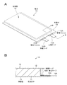
- FIG. 1A is a perspective view illustrating a configuration example of a film-clad battery according to the first embodiment of the present technology.
- 1B is a cross-sectional view taken along line IB-IB in FIG. 1A. It is an exploded perspective view showing an example of 1 composition of a film exterior type battery concerning a 1st embodiment of this art. It is a partial expanded sectional view which shows one structural example of a battery element.
- FIG. 4A is a plan view illustrating a configuration example of a positive electrode current collector.
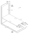
- FIG. 4B is a plan view illustrating a configuration example of the negative electrode current collector. It is an exploded perspective view showing an example of 1 composition of a film exterior type battery concerning a 2nd embodiment of this art.
- a film-clad battery (hereinafter simply referred to as “battery”) 10 is a so-called flat or square lithium ion polymer battery, and has a positive electrode lead 14A.
- the battery element 11 to which the negative electrode lead 14B is attached is housed inside the film-shaped exterior member 12, and can be reduced in size, weight, and thickness.
- the positive electrode lead 14 ⁇ / b> A and the negative electrode lead 14 ⁇ / b> B are led out from the inside of the exterior material 12 to the outside, for example, in the same direction.
- the positive electrode lead 14 ⁇ / b> A and the negative electrode lead 14 ⁇ / b> B are made of a metal material such as aluminum (Al), copper (Cu), nickel (Ni), or stainless steel, respectively, and have a thin plate shape or a mesh shape, respectively.
- the end portion side of the battery element 11 from which the positive electrode lead 14A and the negative electrode lead 14B are derived is referred to as a top side
- the opposite end portion side is referred to as a bottom side.
- the side of the both ends located between the top side and the bottom side is called a side side.
- the exterior example 12 has a rectangular shape and is folded back so that each side overlaps from the center.
- a cut or the like may be provided in advance at the folding boundary, but it is preferable that no cut or the like is provided in advance. If there is a cut or the like, the exterior material 12 may be cleaved at the bottom side of the battery element 11 due to an increase in internal pressure in the exterior material 12 due to gas generation or temperature rise at the time of abnormality. In this embodiment, since the breaking mechanism is provided on the top side, it is not desirable that the exterior material 12 is cleaved on the bottom side of the battery element 11.
- the battery element 11 is sandwiched between the folded exterior materials 12, and the exterior material 12 is sealed on the top side and the side side around the battery element 11.
- Examples of the sealing form include adhesion such as heat fusion.
- the exterior material 12 has an accommodating portion 16 for accommodating the battery element 11 on one surface to be overlaid. This accommodating part 16 is formed by deep drawing, for example.
- the exterior material 12 has an adhesive layer 17 on the other surface to be overlaid, and the exterior material 12 and the battery element 11 are bonded to each other via the adhesive layer 17.
- first surface 12A one surface of the exterior material 12 on the side bonded through the adhesive layer 17
- second surface 12B One main surface of the battery element 11 facing the second surface 12B of the exterior material 12
- a front surface One main surface of the battery element 11 facing the second surface 12B of the exterior material 12
- the other main surface of the battery element 11 facing the first surface 12A of the exterior material 12 is referred to as a back surface.
- an adhesive layer 17 may be provided on the back surface of the battery element 11, or on both the first surface 12A of the exterior material 12 and the back surface of the battery element 11.
- An adhesive layer 17 may be provided.
- the exterior material 12 is made of, for example, a laminate film having flexibility.
- the packaging material 12 has a configuration in which, for example, a heat sealing resin layer, a metal layer, and a surface protective layer are sequentially laminated.
- the surface on the heat-sealing resin layer side is the surface on the side where the battery element 11 is accommodated.
- the material for the heat-sealing resin layer include polypropylene (PP) and polyethylene (PE).
- the material for the metal layer include aluminum.
- Examples of the material for the surface protective layer include nylon (Ny).
- the exterior material 12 is made of, for example, a rectangular aluminum laminated film in which a nylon film, an aluminum foil, and a polyethylene film are bonded together in this order.
- the packaging material 12 is disposed, for example, so that the polyethylene film side and the battery element 11 face each other, and the outer edge portions are in close contact with each other by fusion bonding or an adhesive.
- An adhesion film (sealant) 15A is inserted between the exterior material 12 and the positive electrode lead 14A
- an adhesion film (sealant) 15B is inserted between the exterior material 12 and the negative electrode lead 14B.
- the adhesion films 15A and 15B are made of a material having adhesion to the positive electrode lead 14A and the negative electrode lead 14B, for example, a polyolefin resin such as polyethylene, polypropylene, modified polyethylene, or modified polypropylene, in order to prevent intrusion of outside air. .
- the exterior material 12 may be configured by a laminated film having another structure, a polymer film such as polypropylene, or a metal film, instead of the above-described laminated film.
- a laminate film in which an aluminum film is used as a core and a polymer film is laminated on one or both sides thereof may be used.
- a coloring material is included in the thing further provided with a colored layer, and / or at least 1 layer chosen from a heat-fusion resin layer and a surface protective layer.
- a thing may be used.
- the adhesive layer may include a coloring material.
- the adhesive layer 17 is made of an adhesive material such as an adhesive material.
- an adhesive material for example, an acrylic adhesive, a rubber adhesive, a silicon adhesive, or the like can be used.
- adhesion pressure sensitivehesadhesion
- the adhesive layer is regarded as a kind of adhesive layer.
- the adhesive layer 17 may be one in which an adhesive is applied to both surfaces of a film-like support. Examples of the adhesive layer 17 having such a configuration include a double-sided adhesive tape and a double-sided adhesive film.
- an adhesive tape 18A as an adhesive is provided on the positive electrode lead 14A between the battery element 11 and the adhesion film 15A.
- an adhesive tape 18B as an adhesive material is provided on the inner surface of the exterior material 12 on the second surface 12B side and in contact with the adhesive tape 18A when the exterior material 12 is closed.
- the adhesive tapes 18 ⁇ / b> A and 18 ⁇ / b> B are provided inside the sealing portion of the exterior material 12.
- the adhesive tape 18 ⁇ / b> A and the adhesive tape 18 ⁇ / b> B come into contact and the positive electrode lead 14 ⁇ / b> A and the second surface 12 ⁇ / b> B of the exterior material 12 are adhered. Will do.
- the adhesive tape 18A and the adhesive tape 18B utilize the fact that the second surface 12B side of the exterior material 12 is deformed and bulges due to an increase in internal pressure in the exterior material 12 due to gas generation or temperature rise at the time of abnormality. It is for breaking.
- the breaking mechanism for breaking the positive electrode lead 14A is non-returning, that is, the positive electrode lead 14A does not return to its original state after breaking.
- the positive electrode lead 14A or the negative electrode lead 14B may be bonded to the second surface 12B.
- the materials constituting the positive electrode lead 14A and the negative electrode lead 14B are different, the lower strength of the outer packaging material 12 is selected.
- the two surfaces 12B may be adhered.
- the positive electrode lead 14A is often made of aluminum (Al) and the negative electrode lead 14B is made of nickel (Ni). In such a case, the positive electrode lead 14A has lower strength. Therefore, the positive electrode lead 14A may be bonded to the second surface 12B.
- both the positive electrode lead 14A and the negative electrode lead 14B may be bonded to the second surface 12B.
- the adhesive tape 18A and the adhesive tape 18B may be configured by using any material as long as it has an adhesive force that can reliably bond the positive electrode lead 14A and the exterior material 12. For example, The same material as that of the adhesive layer 17 is used.
- the battery element 11 is a battery element having a stack-type electrode structure having a flat shape.
- the positive electrode lead 14A and the negative electrode lead 14B are led out from one end of the battery element 11 in the same direction, for example.
- the battery element 11 is a so-called lithium ion polymer secondary battery.
- the battery element 11 includes a positive electrode 21, a negative electrode 22, a separator 23, and an electrolyte layer 24.
- the positive electrode 21, the negative electrode 22, and the separator 23 have, for example, a rectangular shape.
- the battery element 11 has, for example, a structure in which a positive electrode 21 and a negative electrode 22 are stacked with a separator 23 interposed therebetween.
- An electrolyte layer 24 is provided between the positive electrode 21 and the separator 23 and between the negative electrode 22 and the separator 23, respectively.
- the positive electrode 21 has a structure in which a positive electrode active material layer 21B is provided on one or both surfaces of a positive electrode current collector 21A. Although not shown, the positive electrode active material layer 21B may be provided only on one surface of the positive electrode current collector 21A.
- the positive electrode current collector 21A is made of, for example, a metal foil such as an aluminum foil, a nickel foil, or a stainless steel foil.
- the positive electrode active material layer 21B includes, for example, a positive electrode active material that can occlude and release lithium as an electrode reactant.
- the positive electrode active material layer 21B may further contain an additive as necessary. As the additive, for example, at least one of a conductive agent and a binder can be used.
- the positive electrode current collector 21A includes a positive electrode active material layer forming part 21M and a positive electrode current collector exposed part 21N.
- the positive electrode active material layer forming portion 21M has, for example, a rectangular shape when viewed from a direction perpendicular to the main surface of the positive electrode current collector 21A.
- the positive electrode active material layer 21B is provided on both surfaces or one surface of the positive electrode active material layer forming portion 21M.
- the cathode current collector exposed portion 21N extends from a part of one side of the cathode active material layer forming portion 21M. However, as shown by a two-dot chain line in FIG.
- the positive electrode current collector exposed portion 21N may extend from the whole of one side of the positive electrode active material layer forming portion 21M, and the positive electrode current collector exposed portion 21N
- the shape is not particularly limited. In a state where the positive electrode 21, the negative electrode 22, and the separator 23 are stacked, the plurality of positive electrode current collector exposed portions 21N are joined together, and the joined positive electrode current collector exposed portions 21N are electrically connected to the positive electrode lead 14A.
- the positive electrode current collector 21A is made of, for example, a metal foil such as an aluminum foil, a nickel foil, or a stainless steel foil.
- lithium-containing compounds such as lithium oxide, lithium phosphorus oxide, lithium sulfide, or an intercalation compound containing lithium are suitable, and two or more of these are used. May be used in combination.
- a lithium-containing compound containing lithium, a transition metal element, and oxygen (O) is preferable.
- examples of such a lithium-containing compound include a lithium composite oxide having a layered rock salt structure shown in Formula (A) and a lithium composite phosphate having an olivine structure shown in Formula (B). Can be mentioned.
- the lithium-containing compound is more preferably one containing at least one member selected from the group consisting of cobalt (Co), nickel, manganese (Mn), and iron (Fe) as a transition metal element.
- Examples of such a lithium-containing compound include a lithium composite oxide having a layered rock salt type structure represented by the formula (C), formula (D), or formula (E), and a spinel type compound represented by the formula (F). Examples thereof include a lithium composite oxide having a structure, or a lithium composite phosphate having an olivine structure shown in the formula (G).
- LiNi 0.50 Co 0.20 Mn 0.30 O 2 Li a CoO 2 (A ⁇ 1), Li b NiO 2 (b ⁇ 1), Li c1 Ni c2 Co 1-c2 O 2 (c1 ⁇ 1, 0 ⁇ c2 ⁇ 1), Li d Mn 2 O 4 (d ⁇ 1) or Li e FePO 4 (e ⁇ 1).
- M1 represents at least one element selected from Groups 2 to 15 excluding nickel and manganese.
- X represents at least one of Group 16 and Group 17 elements other than oxygen.
- P, q, y, z are 0 ⁇ p ⁇ 1.5, 0 ⁇ q ⁇ 1.0, 0 ⁇ r ⁇ 1.0, ⁇ 0.10 ⁇ y ⁇ 0.20, 0 ⁇ (The value is within the range of z ⁇ 0.2.)
- M2 represents at least one element selected from Group 2 to Group 15.
- a and b are 0 ⁇ a ⁇ 2.0 and 0.5 ⁇ b ⁇ 2.0. It is a value within the range.
- M3 is cobalt, magnesium (Mg), aluminum, boron (B), titanium (Ti), vanadium (V), chromium (Cr), iron, copper, zinc (Zn), It represents at least one member selected from the group consisting of zirconium (Zr), molybdenum (Mo), tin (Sn), calcium (Ca), strontium (Sr), and tungsten (W), f, g, h, j, and k.
- M4 is at least one selected from the group consisting of cobalt, manganese, magnesium, aluminum, boron, titanium, vanadium, chromium, iron, copper, zinc, molybdenum, tin, calcium, strontium, and tungsten.
- M, n, p and q are 0.8 ⁇ m ⁇ 1.2, 0.005 ⁇ n ⁇ 0.5, ⁇ 0.1 ⁇ p ⁇ 0.2, 0 ⁇ q ⁇ 0. (The value is within a range of 1.
- the composition of lithium varies depending on the state of charge and discharge, and the value of m represents a value in a fully discharged state.
- M5 is at least one selected from the group consisting of nickel, manganese, magnesium, aluminum, boron, titanium, vanadium, chromium, iron, copper, zinc, molybdenum, tin, calcium, strontium, and tungsten.
- Represents one, r, s, t and u are 0.8 ⁇ r ⁇ 1.2, 0 ⁇ s ⁇ 0.5, ⁇ 0.1 ⁇ t ⁇ 0.2, 0 ⁇ u ⁇ 0.1 (Note that the composition of lithium varies depending on the state of charge and discharge, and the value of r represents the value in a fully discharged state.)
- M6 is at least one selected from the group consisting of cobalt, nickel, magnesium, aluminum, boron, titanium, vanadium, chromium, iron, copper, zinc, molybdenum, tin, calcium, strontium, and tungsten.
- V, w, x, and y are 0.9 ⁇ v ⁇ 1.1, 0 ⁇ w ⁇ 0.6, 3.7 ⁇ x ⁇ 4.1, and 0 ⁇ y ⁇ 0.1. (Note that the lithium composition varies depending on the state of charge and discharge, and the value of v represents a value in a fully discharged state.)
- Li z M7PO 4 (G) (In the formula (G), M7 is composed of cobalt, manganese, iron, nickel, magnesium, aluminum, boron, titanium, vanadium, niobium (Nb), copper, zinc, molybdenum, calcium, strontium, tungsten and zirconium. Represents at least one member of the group, z is a value in the range of 0.9 ⁇ z ⁇ 1.1, wherein the composition of lithium depends on the state of charge and discharge, and the value of z Represents the value at.)
- positive electrode materials capable of inserting and extracting lithium include inorganic compounds not containing lithium, such as MnO 2 , V 2 O 5 , V 6 O 13 , NiS, and MoS.
- the positive electrode material capable of inserting and extracting lithium may be other than the above.
- the positive electrode material illustrated above may be mixed 2 or more types by arbitrary combinations.
- binder examples include resin materials such as polyvinylidene fluoride (PVdF), polytetrafluoroethylene (PTFE), polyacrylonitrile (PAN), polyamide (PA), styrene butadiene rubber (SBR), and carboxymethyl cellulose (CMC). And at least one selected from copolymers mainly composed of these resin materials.
- PVdF polyvinylidene fluoride
- PTFE polytetrafluoroethylene
- PAN polyacrylonitrile
- PA polyamide
- SBR styrene butadiene rubber
- CMC carboxymethyl cellulose
- the conductive agent examples include carbon materials such as graphite, carbon black, ketjen black, carbon nanotubes, and carbon nanofibers, and one or more of them are used in combination.
- a metal material or a conductive polymer material may be used as long as it is a conductive material.
- the negative electrode 22 has a structure in which a negative electrode active material layer 22B is provided on one surface or both surfaces of a negative electrode current collector 22A, and the negative electrode active material layer 22B and the positive electrode active material layer 21B are arranged to face each other. Yes. Although not shown, the negative electrode active material layer 22B may be provided only on one surface of the negative electrode current collector 22A.
- the negative electrode current collector 22A is made of, for example, a metal foil such as a copper foil, a nickel foil, or a stainless steel foil.
- the negative electrode current collector 22A includes a negative electrode active material layer forming part 22M and a negative electrode current collector exposed part 22N.
- the negative electrode active material layer forming part 22M has, for example, a rectangular shape when viewed from a direction perpendicular to the main surface of the negative electrode current collector 22A.
- a negative electrode active material layer 22B is provided on both surfaces or one surface of the negative electrode active material layer forming portion 22M.
- the negative electrode current collector exposed portion 22N extends from a part of one side of the negative electrode active material layer forming portion 22M. However, as shown by a two-dot chain line in FIG.
- the negative electrode current collector exposed portion 22N may be extended from the whole of one side of the negative electrode active material layer forming portion 22M, and the negative electrode current collector exposed portion 22N
- the shape is not particularly limited.
- the plurality of negative electrode current collector exposed portions 22N are bonded to each other, and the bonded negative electrode current collector exposed portions 22N are electrically connected to the negative electrode lead 14B.
- the negative electrode current collector 22A is made of, for example, a metal foil such as a copper foil, a nickel foil, or a stainless steel foil.
- the negative electrode active material layer 22B contains one or more negative electrode active materials capable of inserting and extracting lithium.
- the negative electrode active material layer 22B may further contain additives such as a binder and a conductive agent as necessary.
- Examples of the negative electrode active material include carbon materials such as non-graphitizable carbon, graphitizable carbon, graphite, pyrolytic carbons, cokes, glassy carbons, organic polymer compound fired bodies, carbon fibers, and activated carbon. Is mentioned.
- examples of coke include pitch coke, needle coke, and petroleum coke.
- An organic polymer compound fired body refers to a carbonized material obtained by firing a polymer material such as phenol resin or furan resin at an appropriate temperature, and part of it is non-graphitizable carbon or graphitizable carbon.
- These carbon materials are preferable because the change in crystal structure that occurs during charge and discharge is very small, a high charge and discharge capacity can be obtained, and good cycle characteristics can be obtained.
- graphite is preferable because it has a high electrochemical equivalent and can provide a high energy density.
- non-graphitizable carbon is preferable because excellent cycle characteristics can be obtained.
- a battery having a low charge / discharge potential specifically, a battery having a charge / discharge potential close to that of lithium metal is preferable because a high energy density of the battery 10 can be easily realized.
- a material containing at least one of a metal element and a metalloid element as a constituent element for example, an alloy, a compound, or a mixture
- a material containing at least one of a metal element and a metalloid element as a constituent element for example, an alloy, a compound, or a mixture
- the alloy includes an alloy including one or more metal elements and one or more metalloid elements in addition to an alloy composed of two or more metal elements.
- the nonmetallic element may be included.
- Examples of such a negative electrode active material include a metal element or a metalloid element capable of forming an alloy with lithium.
- a metal element or a metalloid element capable of forming an alloy with lithium.
- magnesium, boron, aluminum, titanium, gallium (Ga), indium (In), silicon (Si), germanium (Ge), tin, lead (Pb), bismuth (Bi), cadmium (Cd), Silver (Ag), zinc, hafnium (Hf), zirconium, yttrium (Y), palladium (Pd), or platinum (Pt) can be used. These may be crystalline or amorphous.
- the negative electrode active material those containing a 4B group metal element or semi-metal element in the short-period type periodic table as a constituent element are preferable, and more preferable are those containing at least one of silicon and tin as a constituent element. This is because silicon and tin have a large ability to occlude and release lithium, and a high energy density can be obtained.
- Examples of such a negative electrode active material include a simple substance, an alloy or a compound of silicon, a simple substance, an alloy or a compound of tin, or a material having one or more phases thereof at least in part.
- Examples of the silicon alloy include, as the second constituent element other than silicon, tin, nickel, copper, iron, cobalt, manganese, zinc, indium, silver, titanium, germanium, bismuth, antimony (Sb), and chromium.
- the thing containing at least 1 sort (s) of a group is mentioned.
- As an alloy of tin for example, as a second constituent element other than tin, among the group consisting of silicon, nickel, copper, iron, cobalt, manganese, zinc, indium, silver, titanium, germanium, bismuth, antimony and chromium The thing containing at least 1 sort (s) of these is mentioned.
- tin compound or silicon compound examples include those containing oxygen or carbon, and may contain the second constituent element described above in addition to tin or silicon.
- the Sn-based negative electrode active material cobalt, tin, and carbon are included as constituent elements, the carbon content is 9.9 mass% or more and 29.7 mass% or less, and tin and cobalt A SnCoC-containing material in which the proportion of cobalt with respect to the total is 30% by mass to 70% by mass is preferable. This is because a high energy density can be obtained in such a composition range, and excellent cycle characteristics can be obtained.
- This SnCoC-containing material may further contain other constituent elements as necessary.
- other constituent elements for example, silicon, iron, nickel, chromium, indium, niobium, germanium, titanium, molybdenum, aluminum, phosphorus (P), gallium, or bismuth are preferable, and two or more kinds may be included. This is because the capacity or cycle characteristics can be further improved.
- This SnCoC-containing material has a phase containing tin, cobalt, and carbon, and this phase preferably has a low crystallinity or an amorphous structure.
- this SnCoC-containing material it is preferable that at least a part of carbon that is a constituent element is bonded to a metal element or a metalloid element that is another constituent element.
- the decrease in cycle characteristics is thought to be due to the aggregation or crystallization of tin or the like, but this is because such aggregation or crystallization can be suppressed by combining carbon with other elements. .
- XPS X-ray photoelectron spectroscopy
- the peak of the carbon 1s orbital (C1s) appears at 284.5 eV in an energy calibrated apparatus so that the peak of the gold atom 4f orbital (Au4f) is obtained at 84.0 eV if it is graphite. .
- Au4f gold atom 4f orbital
- it will appear at 284.8 eV.
- the charge density of the carbon element increases, for example, when carbon is bonded to a metal element or a metalloid element, the C1s peak appears in a region lower than 284.5 eV.
- the peak of the synthetic wave of C1s obtained for the SnCoC-containing material appears in a region lower than 284.5 eV
- at least a part of the carbon contained in the SnCoC-containing material is a metal element or a half of other constituent elements. Combined with metal elements.
- the C1s peak is used to correct the energy axis of the spectrum.
- the C1s peak of the surface-contaminated carbon is set to 284.8 eV, which is used as an energy standard.
- the waveform of the C1s peak is obtained as a shape including the surface contamination carbon peak and the carbon peak in the SnCoC-containing material. Therefore, by analyzing using, for example, commercially available software, the surface contamination The carbon peak and the carbon peak in the SnCoC-containing material are separated. In the waveform analysis, the position of the main peak existing on the lowest bound energy side is used as the energy reference (284.8 eV).
- Examples of other negative electrode active materials include metal oxides or polymer compounds that can occlude and release lithium.
- Examples of the metal oxide include lithium titanium oxide containing titanium and lithium, such as lithium titanate (Li 4 Ti 5 O 12 ), iron oxide, ruthenium oxide, or molybdenum oxide.
- Examples of the polymer compound include polyacetylene, polyaniline, and polypyrrole.
- the binder is, for example, at least selected from resin materials such as polyvinylidene fluoride, polytetrafluoroethylene, polyacrylonitrile, polyamide, styrene butadiene rubber and carboxymethyl cellulose, and copolymers mainly composed of these resin materials.
- resin materials such as polyvinylidene fluoride, polytetrafluoroethylene, polyacrylonitrile, polyamide, styrene butadiene rubber and carboxymethyl cellulose, and copolymers mainly composed of these resin materials.
- One type is used.
- the conductive agent the same carbon material as that of the positive electrode active material layer 21B can be used.
- the separator 23 separates the positive electrode 21 and the negative electrode 22 and allows lithium ions to pass through while preventing a short circuit of current due to contact between the two electrodes.
- the separator 23 is made of, for example, a porous film made of a resin such as polytetrafluoroethylene, polypropylene, or polyethylene, and may have a structure in which two or more kinds of these porous films are laminated.
- a porous film made of polyolefin is preferable because it has an excellent short-circuit prevention effect and can improve the safety of the battery 10 due to a shutdown effect.
- polyethylene is preferable as a material constituting the separator 23 because it can obtain a shutdown effect within a range of 100 ° C.
- the porous film may have a structure of three or more layers in which a polypropylene layer, a polyethylene layer, and a polypropylene layer are sequentially laminated.
- the separator 23 may be provided with a resin layer on one side or both sides of a porous film as a base material.
- the resin layer is a porous matrix resin layer on which an inorganic substance is supported. Thereby, oxidation resistance can be obtained and deterioration of the separator 23 can be suppressed.
- the matrix resin for example, polyvinylidene fluoride, hexafluoropropylene (HFP), polytetrafluoroethylene, or the like can be used, and a copolymer thereof can also be used.
- the inorganic substance a metal, a semiconductor, or an oxide or nitride thereof can be given.
- examples of the metal include aluminum and titanium
- examples of the semiconductor include silicon and boron.
- a thing with substantially no electroconductivity and a large heat capacity is preferable. This is because if the heat capacity is large, it is useful as a heat sink during heat generation of the current, and thermal runaway of the battery 10 can be further suppressed.
- inorganic substances examples include alumina (Al 2 O 3 ), boehmite (alumina monohydrate), talc, boron nitride (BN), aluminum nitride (AlN), titanium dioxide (TiO 2 ), silicon oxide (SiO 2 ). x ) oxides or nitrides.
- the inorganic substance mentioned above may be contained in the porous membrane as a base material.
- the particle size of the inorganic substance is preferably in the range of 1 nm to 10 ⁇ m. If it is smaller than 1 nm, it is difficult to obtain, and even if it can be obtained, it is not worth the cost. If it is larger than 10 ⁇ m, the distance between the electrodes becomes large, and a sufficient amount of active material cannot be obtained in a limited space, resulting in a low battery capacity.
- the resin layer can be formed as follows, for example. That is, a slurry composed of a matrix resin, a solvent, and an inorganic substance is applied onto a base material (porous membrane), passed through a poor solvent of the matrix resin and a parent solvent bath of the solvent, phase-separated, and then dried.
- the electrolyte layer 24 includes a non-aqueous electrolyte and a polymer compound serving as a holding body that holds the non-aqueous electrolyte, and the polymer compound is swollen by the non-aqueous electrolyte.
- the content ratio of the polymer compound can be adjusted as appropriate.
- a gel electrolyte is preferable because high ion conductivity can be obtained and leakage of the battery 10 can be prevented.
- the non-aqueous electrolyte contains, for example, a solvent and an electrolyte salt.
- the solvent include 4-fluoro-1,3-dioxolan-2-one, ethylene carbonate, propylene carbonate, butylene carbonate, vinylene carbonate, dimethyl carbonate, diethyl carbonate, ethyl methyl carbonate, ⁇ -butyrolactone, and ⁇ -valerolactone.
- the electrolyte layer 24 may contain a known additive in order to improve battery characteristics.
- the electrolyte salt may contain one kind or a mixture of two or more kinds of materials.
- the electrolyte salt include lithium hexafluorophosphate (LiPF 6 ), bis (pentafluoroethanesulfonyl) imide lithium (Li (C 2 F 5 SO 2 ) 2 N), lithium perchlorate (LiClO 4 ), Lithium hexafluoroarsenate (LiAsF 6 ), lithium tetrafluoroborate (LiBF 4 ), lithium trifluoromethanesulfonate (LiSO 3 CF 3 ), lithium bis (trifluoromethanesulfonyl) imide (Li (CF 3 SO 2 ) 2 N), tris (trifluoromethanesulfonyl) methyllithium (LiC (SO 2 CF 3 ) 3 ), lithium chloride (LiCl) and lithium bromide (LiBr).
- LiPF 6 lithium hexa
- polymer compound examples include polyacrylonitrile, polyvinylidene fluoride, a copolymer of vinylidene fluoride and hexafluoropropylene, polytetrafluoroethylene, polyhexafluoropropylene, polyethylene oxide, polypropylene oxide, polyphosphazene, and polysiloxane.
- polyacrylonitrile, polyvinylidene fluoride, polyhexafluoropropylene, or polyethylene oxide is preferable from the viewpoint of electrochemical stability.
- an inorganic material similar to the inorganic material described in the description of the resin layer of the separator 23 may be included in the electrolyte layer 24. This is because the heat resistance can be further improved.
- the battery 10 is configured as described above.
- the battery 10 has an open circuit voltage (that is, a battery voltage) when fully charged, for example, 2.80 V or more and 6.00 V or less, or 3.60 V or more and 6.00 V or less, preferably 4.25 V or more and 6.00 V or less. Alternatively, it may be designed to be in the range of 4.20V to 4.50V, more preferably 4.30V to 4.55V.
- the open circuit voltage at the time of full charge is 4.25 V or more in a battery using, for example, a layered rock salt type lithium composite oxide as a positive electrode active material, the same positive electrode active voltage as compared with a 4.20 V battery. Even if it is a substance, since the amount of lithium released per unit mass increases, the amounts of the positive electrode active material and the negative electrode active material are adjusted accordingly, and a high energy density can be obtained.
- lithium ions are released from the positive electrode active material layer 21B and inserted into the negative electrode active material layer 22B through the electrolytic solution.
- lithium ions are released from the negative electrode active material layer 22B and inserted into the positive electrode active material layer 21B through the electrolytic solution.
- the positive electrode 21 is produced as follows. First, for example, a positive electrode active material, a conductive agent, and a binder are mixed to prepare a positive electrode mixture, and this positive electrode mixture is dispersed in a solvent such as N-methyl-2-pyrrolidone (NMP). A paste-like positive electrode mixture slurry is prepared. Next, the positive electrode mixture slurry is applied to the belt-like positive electrode current collector 21A, the solvent is dried, and compression-molding is performed by a roll press or the like to form the positive electrode active material layer 21B, thereby producing the belt-like positive electrode 21. .
- NMP N-methyl-2-pyrrolidone
- a precursor solution containing a solvent, an electrolyte salt, a polymer compound, and a mixed solvent is applied to the positive electrode 21, and the mixed solvent is volatilized to form the electrolyte layer 24.
- the positive electrode 21 is cut into a shape corresponding to the battery element 11.
- the electrolyte layer 24 may be formed after the positive electrode 21 is cut.
- the negative electrode 22 is produced as follows. First, for example, a negative electrode active material and a binder are mixed to prepare a negative electrode mixture, and this negative electrode mixture is dispersed in a solvent such as N-methyl-2-pyrrolidone (NMP) or methyl ethyl ketone (MEK). Thus, a paste-like negative electrode mixture slurry is prepared. Next, the negative electrode mixture slurry is applied to the strip-shaped negative electrode current collector 22A, the solvent is dried, and the negative electrode active material layer 22B is formed by compression molding using a roll press or the like, and the strip-shaped negative electrode 22 is manufactured. .
- NMP N-methyl-2-pyrrolidone
- MEK methyl ethyl ketone
- a precursor solution containing a solvent, an electrolyte salt, a polymer compound, and a mixed solvent is applied to the negative electrode 22, and the mixed solvent is volatilized to form the electrolyte layer 24.
- the negative electrode 22 is cut into a shape corresponding to the battery element 11.
- the electrolyte layer 24 may be formed after the negative electrode 22 is cut.
- the battery element 11 is produced as follows. First, a polypropylene microporous film or the like is cut into a rectangular shape to produce a separator 23. Next, the plurality of positive electrodes 21, negative electrodes 22, and separators 23 obtained as described above are separated into separators 23, positive electrodes 21, separators 23, negative electrodes 22, separators 23,..., For example, as shown in FIG. Then, the separator 23, the negative electrode 22, the separator, the positive electrode 21, and the separator 23 are stacked in this order to produce the flat battery element 11. Next, the positive electrode current collector exposed portions 21N of the plurality of stacked positive electrodes 21 are bonded together, and the positive electrode lead 14A is electrically connected to the bonded positive electrode current collector exposed portions 21N.
- connection method examples include ultrasonic welding, resistance welding, and soldering. However, in consideration of damage to the connection portion due to heat, it is possible to use a method with less thermal influence such as ultrasonic welding and resistance welding. preferable.
- the exterior material 12 is prepared in which the adhesive layer 17 is provided on the first surface 12A and the adhesive tape 18B is provided on the second surface 12B.
- the exterior material 12 is folded from the center, and the exterior material 12 is overlapped and bonded while sandwiching the battery element 11 between the exterior materials 12.
- the back surface of the battery element 11 and the first surface 12A of the exterior material 12 are bonded together via the layer 17.
- the adhesion films 15A and 15B are inserted between the positive electrode lead 14A and the negative electrode lead 14B and the exterior material 12.
- adhesion films 15A and 15B may be provided in advance on the positive electrode lead 14A and the negative electrode lead 14B, respectively.
- the heat-sealing resin layers of the overlaid exterior material 12 are bonded to each other by heat-sealing, and an adhesive tape 18A provided on the positive electrode lead 14A.
- the adhesive tape 18B provided on the second surface 12B are bonded together. Thereby, the battery element 11 is sealed with the exterior material 12, and the battery 10 is obtained.
- the battery 10 is molded by heat pressing as necessary. More specifically, the battery 10 is heated at a temperature higher than normal temperature while being pressurized.
- the positive electrode active material layer 21B and the negative electrode active material layer 22B can be impregnated with the electrolyte constituting the electrolyte layer 24, and the adhesion between the electrolyte layer 24, the positive electrode 21, and the negative electrode 22 can be improved.
- the adhesiveness of positive electrode active materials and negative electrode active materials can be improved, and the contact resistance of a positive electrode active material and a negative electrode active material can be reduced.
- the battery 10 according to the first embodiment of the present technology is manufactured as described above.
- the back surface of the battery element 11 is bonded to the first surface 12 ⁇ / b> A of the exterior material 12 via the adhesive layer 17. Therefore, when the second surface 12B of the exterior material 12 expands due to gas generation or temperature rise at the time of abnormality, the second surface 12B pulls up the positive electrode lead 14A via the adhesive tape 18B and the adhesive tape 18A, thereby causing the positive electrode lead 14A. To break. By breaking the positive electrode lead 14A in this way, it is possible to cut off the current to the battery element 11 at the time of abnormality.
- the positive electrode lead 14A is similarly broken not only when overcharged, but also when the internal pressure in the exterior material 12 rises due to an abnormal environmental temperature or a temperature rise due to a large current during a short circuit. That is, the current can be interrupted at the time of abnormality without reducing the characteristics of the battery 10, and the battery 10 can be safely stopped.
- the first embodiment it is possible to realize a battery having a safety mechanism without interrupting the current at the time of abnormality, without damaging the resistance, and without changing the shape of the battery element 11.
- the external appearance of the battery 30 in the second embodiment is a so-called flat or square lithium ion polymer battery similar to that of the first embodiment, and the battery element 11 to which the positive electrode lead 14A and the negative electrode lead 14B are attached is a film.
- the outer casing 12 is housed in a shape, and can be reduced in size, weight, and thickness.
- the external configuration of the battery 30, the configuration of the battery element 11, the exterior material 12, the positive electrode lead 14A, the negative electrode lead 14B, the adhesion film 15A, and the adhesion film 15B and the manufacturing method are the same as those in the first embodiment.
- the contents of the embodiment are used and the description thereof is omitted.
- the cable 31 is wound around the positive electrode lead 14A between the battery element 11 and the adhesion film 15A.
- the cable 31 is formed in a string shape having a diameter of about 1 mm or less and has an insulating property.
- An adhesive tape 33A is provided via a belt-like member 32 at the end of the cable 31 opposite to the side in contact with the positive electrode lead 14A.
- the adhesive tape 33B is provided on the inner surface of the exterior material 12 on the second surface 12B side and in contact with the adhesive tape 33A when the exterior material 12 is closed. Thereby, in a state where the battery element 11 is sealed with the exterior material 12, the adhesive tape 33 ⁇ / b> A and the adhesive tape 33 ⁇ / b> B come into contact, and the positive electrode lead 14 ⁇ / b> A and the second surface 12 ⁇ / b> B of the exterior material 12 are adhered.
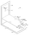
- the cable 31, the belt-like member 32, the adhesive tape 33A, and the adhesive tape 33B utilize the fact that the second surface 12B side of the exterior material 12 is deformed and bulges due to an increase in internal pressure of the exterior material 12 due to gas generation or temperature rise at the time of abnormality.
- the cable 31 is preferably configured to be thin so as to easily bite into the positive electrode lead 14 ⁇ / b> A while having a strength that does not break before the positive electrode lead 14 is broken in order to bite and break the positive electrode lead 14.
- the cable 31 may be configured using any material having such strength.
- the cable 31 may be wound with either the positive electrode lead 14A or the negative electrode lead 14B.
- the cable 31 may be wound around a lower strength.
- the positive electrode lead 14A is often made of aluminum (Al) and the negative electrode lead 14B is made of nickel (Ni).
- the positive electrode lead 14A has lower strength. Therefore, the cable 31 may be wound around the positive electrode lead 14A. This is because the present technology breaks the electrode lead and interrupts the current when the second surface 12B (housing portion 16) of the exterior material 12 expands, so that the electrode lead with low strength is broken. This is because the current can be cut off more reliably.
- the cable 31 may be provided on both the positive electrode lead 14A and the negative electrode lead 14B, and both the positive electrode lead 14A and the negative electrode lead 14B may be bonded to the second surface 12B.
- the back surface of the battery element 11 is bonded to the first surface 12A of the exterior material 12 via the adhesive layer 17 as in the first embodiment.
- the battery 30 according to the second embodiment of the present technology is manufactured as described above.
- the back surface of the battery element 11 is bonded to the first surface 12 ⁇ / b> A of the exterior material 12 via the adhesive layer 17. Therefore, when the second surface 12B of the exterior material 12 expands due to gas generation or temperature rise at the time of abnormality, the cable 31 connected to the second surface 12B via the adhesive tape 33B and the adhesive tape 33A connects the positive lead 14A.
- the positive electrode lead 14A is broken by pulling it up. By breaking the positive electrode lead 14A in this way, it is possible to cut off the current to the battery element 11 at the time of abnormality.
- the positive electrode lead 14A is similarly broken not only when it is overcharged but also when the internal pressure of the exterior material 12 rises due to an abnormal environmental temperature or a temperature rise due to a large current during a short circuit. That is, the battery 30 can be safely stopped at the time of abnormality without reducing the characteristics of the battery 30.
- the second embodiment it is possible to realize a battery having a safety mechanism without interrupting the current at the time of abnormality, without damaging the resistance, and without changing the shape of the battery element 11.
- the configurations, methods, steps, shapes, materials, and numerical values of the first and second embodiments described above are merely examples, and different configurations, methods, steps, shapes, materials, and numerical values are necessary as necessary. Etc. may be used.
- the adhesive tape 18 ⁇ / b> A and the adhesive tape 18 ⁇ / b> B are end surfaces on the top side of the battery element 11.
- the positive electrode lead 14 ⁇ / b> A and the second surface 12 ⁇ / b> B of the exterior material 12 may be bonded together. Even in such a configuration, when the second surface 12B of the exterior material 12 expands, the second surface 12B pulls up the positive electrode lead 14A via the adhesive tape 18B and the adhesive tape 18A, so that the positive electrode lead 14A is broken. Can be made.
- An insulating tape 19 may be provided at a location facing the top side end surface of the battery element 11 or the top side end surface of the positive electrode lead 14A.
- the first embodiment and the second embodiment are combined by adopting the first embodiment for one of the positive electrode lead 14A and the negative electrode lead 14B and adopting the second embodiment for the other. Also good.
- the case where the battery 10 and the battery 30 are flat or rectangular has been described as an example.
- the shape of the battery is not limited to this, and a curved shape, a bent shape, or the like is used. You may have.
- a battery having rigidity has been described as an example, but a flexible battery may be used.
- the battery element 11 has a stacked electrode structure
- the configuration of the battery element 11 is not limited to this.
- the battery element 11 may have a wound electrode structure, or may have a structure in which a positive electrode and a negative electrode are folded via a separator.
- the configuration in which the positive electrode lead 14A and the negative electrode lead 14B are led out from the same side of the exterior material 12 in the same direction has been described as an example.
- the positive electrode lead 14A and the negative electrode lead 14B The configuration is not limited to this.
- the positive electrode lead 14 ⁇ / b> A and the negative electrode lead 14 ⁇ / b> B may be led out from different sides of the exterior material 12 in different directions.
- the electrolyte includes a non-aqueous electrolyte and a polymer compound serving as a holding body that holds the non-aqueous electrolyte
- the electrolyte is liquid Or an electrolyte solution thereof.
- the present technology is not limited to this type of battery, and the battery element 11 is made flexible.
- the present technology can be applied to any battery that has a configuration in which it is packaged by the packaging material 12 it has.
- this technique is not limited to a secondary battery, It is also possible to apply to a primary battery.
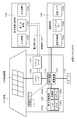
- the electronic device 400 includes an electronic circuit 401 of the electronic device body and a battery pack 300.
- the battery pack 300 is electrically connected to the electronic circuit 401 via the positive terminal 331a and the negative terminal 331b.
- the electronic device 400 has a configuration in which the battery pack 300 is detachable by a user.
- the configuration of the electronic device 400 is not limited to this, and the battery pack 300 is built in the electronic device 400 so that the user cannot remove the battery pack 300 from the electronic device 400. May be.
- the positive terminal 331a and the negative terminal 331b of the battery pack 300 are connected to the positive terminal and the negative terminal of a charger (not shown), respectively.
- the positive terminal 331a and the negative terminal 331b of the battery pack 300 are connected to the positive terminal and the negative terminal of the electronic circuit 401, respectively.
- the electronic device 400 for example, a notebook personal computer, a tablet computer, a mobile phone (for example, a smartphone), a portable information terminal (Personal Digital Assistant: PDA), a display device (LCD, EL display, electronic paper, etc.), imaging, etc.
- Devices eg digital still cameras, digital video cameras, etc.
- audio equipment eg portable audio players
- game machines cordless phones, e-books, electronic dictionaries, radio, headphones, navigation systems, memory cards, pacemakers, hearing aids, Electric tools, electric shavers, refrigerators, air conditioners, TVs, stereos, water heaters, microwave ovens, dishwashers, washing machines, dryers, lighting equipment, toys, medical equipment, robots, road conditioners, traffic lights Etc.
- the electronic circuit 401 includes, for example, a CPU, a peripheral logic unit, an interface unit, a storage unit, and the like, and controls the entire electronic device 400.
- the battery pack 300 includes an assembled battery 301 and a charge / discharge circuit 302.
- the assembled battery 301 is configured by connecting a plurality of secondary batteries 301a in series and / or in parallel.
- the plurality of secondary batteries 301a are connected, for example, in n parallel m series (n and m are positive integers).
- FIG. 8 shows an example in which six secondary batteries 301a are connected in two parallel three series (2P3S).
- the secondary battery 301a the battery according to the first embodiment, the second embodiment, or a modification thereof is used.
- the charging / discharging circuit 302 is a control unit that controls charging / discharging of the assembled battery 301. Specifically, during charging, the charging / discharging circuit 302 controls charging of the assembled battery 301. On the other hand, at the time of discharging (that is, when the electronic device 400 is used), the charging / discharging circuit 302 controls the discharging of the electronic device 400.
- the battery pack 300 includes the assembled battery 301 including a plurality of secondary batteries 301 a has been described as an example. However, the battery pack 300 is replaced with one assembled battery 301. You may employ
- a power storage system including the battery according to the first embodiment, the second embodiment, or a modification thereof in a power storage device will be described.
- This power storage system may be anything as long as it uses power, and includes a simple power device.
- This power system includes, for example, a smart grid, a home energy management system (HEMS), a vehicle, and the like, and can also store electricity.
- HEMS home energy management system
- This power storage system 100 is a residential power storage system, from a centralized power system 102 such as a thermal power generation 102a, a nuclear power generation 102b, and a hydropower generation 102c through a power network 109, an information network 112, a smart meter 107, a power hub 108, etc. Electric power is supplied to the power storage device 103. At the same time, power is supplied to the power storage device 103 from an independent power source such as the home power generation device 104. The electric power supplied to the power storage device 103 is stored. Electric power used in the house 101 is fed using the power storage device 103. The same power storage system can be used not only for the house 101 but also for buildings.
- the house 101 is provided with a home power generation device 104, a power consumption device 105, a power storage device 103, a control device 110 that controls each device, a smart meter 107, a power hub 108, and a sensor 111 that acquires various information.
- Each device is connected by a power network 109 and an information network 112.
- a solar cell, a fuel cell, or the like is used as the home power generation device 104, and the generated power is supplied to the power consumption device 105 and / or the power storage device 103.
- the power consuming device 105 is a refrigerator 105a, an air conditioner 105b, a television receiver 105c, a bath 105d, or the like.
- the electric power consumption device 105 includes an electric vehicle 106.
- the electric vehicle 106 is an electric vehicle 106a, a hybrid car 106b, an electric motorcycle 106c, or the like.
- the power storage device 103 includes the battery according to the first embodiment, the second embodiment, or a modification thereof.
- the smart meter 107 has a function of measuring the usage amount of commercial power and transmitting the measured usage amount to an electric power company.
- the power network 109 may be any one or a combination of DC power supply, AC power supply, and non-contact power supply.
- the various sensors 111 are, for example, human sensors, illuminance sensors, object detection sensors, power consumption sensors, vibration sensors, contact sensors, temperature sensors, infrared sensors, and the like. Information acquired by various sensors 111 is transmitted to the control device 110. Based on the information from the sensor 111, the weather state, the state of a person, and the like can be grasped, and the power consumption device 105 can be automatically controlled to minimize the energy consumption. Furthermore, the control device 110 can transmit information regarding the house 101 to an external power company or the like via the Internet.
- the power hub 108 performs processing such as branching of power lines and DC / AC conversion.
- the communication method of the information network 112 connected to the control device 110 includes a method using a communication interface such as UART (Universal Asynchronous Receiver-Transceiver), Bluetooth (registered trademark), ZigBee (registered trademark).
- a communication interface such as UART (Universal Asynchronous Receiver-Transceiver), Bluetooth (registered trademark), ZigBee (registered trademark).
- the Bluetooth (registered trademark) system is applied to multimedia communication and can perform one-to-many connection communication.
- ZigBee uses the physical layer of IEEE (Institute of Electrical and Electronics Electronics) (802.15.4).
- IEEE802.15.4 is a name of a short-range wireless network standard called PAN (Personal Area Network) or W (Wireless) PAN.
- the control device 110 is connected to an external server 113.
- the server 113 may be managed by any one of the house 101, the power company, and the service provider.
- the information transmitted and received by the server 113 is, for example, information related to power consumption information, life pattern information, power charges, weather information, natural disaster information, and power transactions. These pieces of information may be transmitted / received from a power consuming device in the home (for example, a television receiver) or may be transmitted / received from a device outside the home (for example, a mobile phone). Such information may be displayed on a device having a display function, such as a television receiver, a mobile phone, or a PDA (Personal Digital Assistant).
- a display function such as a television receiver, a mobile phone, or a PDA (Personal Digital Assistant).
- the control device 110 that controls each unit includes a CPU (Central Processing Unit), a RAM (Random Access Memory), a ROM (Read Only Memory), and the like, and is stored in the power storage device 103 in this example.
- the control device 110 is connected to the power storage device 103, the home power generation device 104, the power consumption device 105, the various sensors 111, the server 113 and the information network 112, and adjusts, for example, the amount of commercial power used and the amount of power generation. It has a function. In addition, you may provide the function etc. which carry out an electric power transaction in an electric power market.
- the power generated by the home power generation device 104 is supplied to the power storage device 103.
- the power generated by the home power generation device 104 can be stored. Therefore, even if the generated power of the home power generation device 104 fluctuates, it is possible to perform control such that the amount of power to be sent to the outside is constant or discharge is performed as necessary.
- the electric power obtained by solar power generation is stored in the power storage device 103, and midnight power with a low charge is stored in the power storage device 103 at night, and the power stored by the power storage device 103 is discharged during a high daytime charge. You can also use it.
- control device 110 is stored in the power storage device 103 .
- control device 110 may be stored in the smart meter 107 or may be configured independently.
- the power storage system 100 may be used for a plurality of homes in an apartment house, or may be used for a plurality of detached houses.
- the hybrid vehicle 200 is a hybrid vehicle that employs a series hybrid system.
- the series hybrid system is a vehicle that runs on the power driving force conversion device 203 using electric power generated by a generator that is driven by an engine or electric power that is temporarily stored in a battery.
- the hybrid vehicle 200 includes an engine 201, a generator 202, a power driving force conversion device 203, driving wheels 204a, driving wheels 204b, wheels 205a, wheels 205b, a battery 208, a vehicle control device 209, various sensors 210, and a charging port 211. Is installed.
- the battery 208 the battery according to the first embodiment, the second embodiment, or a modification thereof is used.
- Hybrid vehicle 200 travels using electric power / driving force conversion device 203 as a power source.
- An example of the power driving force conversion device 203 is a motor.
- the electric power / driving force converter 203 is operated by the electric power of the battery 208, and the rotational force of the electric power / driving force converter 203 is transmitted to the driving wheels 204a and 204b.
- DC-AC DC-AC
- AC-DC conversion AC-DC conversion
- the power driving force converter 203 can be applied to either an AC motor or a DC motor.
- the various sensors 210 control the engine speed via the vehicle control device 209 and control the opening (throttle opening) of a throttle valve (not shown).
- the various sensors 210 include a speed sensor, an acceleration sensor, an engine speed sensor, and the like.
- the rotational force of the engine 201 is transmitted to the generator 202, and the electric power generated by the generator 202 by the rotational force can be stored in the battery 208.
- the resistance force at the time of deceleration is applied as a rotational force to the power driving force conversion device 203, and the regenerative electric power generated by the power driving force conversion device 203 by this rotational force is used as the battery 208. Accumulated in.
- the battery 208 is connected to an external power source of the hybrid vehicle 200 via the charging port 211, so that it is possible to receive power from the external power source using the charging port 211 as an input port and store the received power. is there.
- an information processing apparatus that performs information processing related to vehicle control based on information related to the battery may be provided.
- an information processing apparatus for example, there is an information processing apparatus that displays a remaining battery level based on information on the remaining battery level.
- the series hybrid vehicle that runs on the motor using the electric power generated by the generator that is driven by the engine or the electric power that is temporarily stored in the battery has been described as an example.
- the present technology is also effective for a parallel hybrid vehicle that uses both engine and motor outputs as drive sources and switches between the three modes of running with only the engine, running with only the motor, and running with the engine and motor. Applicable.
- the present technology can be effectively applied to a so-called electric vehicle that travels only by a drive motor without using an engine.
- the present technology can also employ the following configurations.
- a flat battery element having an electrode lead at one end; A first surface covering one main surface of the battery element and a second surface covering the other main surface of the battery element, and a peripheral portion of the first surface and the second surface sandwiches the electrode lead.
- a film-like exterior material having an adhesive portion bonded so as to be sandwiched between The first surface and one main surface of the battery element are bonded, The electrode lead is adhered to or connected to the second surface at one end surface of the battery element or between one end of the battery element and the bonding portion of the exterior material.
- the electrode lead is composed of a positive electrode lead and a negative electrode lead, and is bonded to or connected to the second surface using a lower one of the positive electrode lead and the negative electrode lead (1) or The film-clad battery according to (2).
- a flat battery element having an electrode lead at one end; A first surface covering one main surface of the battery element and a second surface covering the other main surface of the battery element, and a peripheral portion of the first surface and the second surface sandwiches the electrode lead.
- a film-clad battery comprising: a film-shaped exterior member having an adhesive portion adhered so as to be sandwiched between; and a breaking mechanism that breaks the electrode lead by deformation of the second surface due to a change in internal pressure in the exterior material.
- a battery pack comprising a control unit for controlling the film-clad battery.
Abstract
電極リードを一端に有する扁平状の電池素子と、電池素子の一方の主面を覆う第1面、および電池素子の他方の主面を覆う第2面を有し、第1面と第2面の周縁部が電極リードを間に挟むようにして接着された接着部を有するフィルム状の外装材とを備え、第1面と電池素子の一方の主面とが接着され、電極リードは、電池素子の一端の面においてまたは電池素子の一端と外装材の接着部との間において、第2面と接着されているか、または繋がれているフィルム外装型電池である。 図1
Description
本技術は、フィルム外装型電池、電池パック、電子機器、電動車両、蓄電装置および電力システムに関する。
従来から二次電池の過充電時および大電流の流入時に電流を遮断する手法として様々なものが提案されている。
例えば、電極と集電体との接触面を調整できる二次電池が提案されている(特許文献1)。また、電極端子との間の電流の経路上に電流遮断素子が設けられた二次電池が提案されている(特許文献2)。さらに、外装体の外側に電流遮断機構が設けられた電池が提案されている(特許文献3)。
しかし、特許文献1に記載の技術では、二次電池の内圧の変化によって電極と集電体との接触面に変化を生じさせ調整を行なうものであるが、異常が生じて内圧が上昇しても内圧が下がると異常状態のままでもその後も継続して使用することができるおそれがある。また、特許文献2に記載の技術では、電流遮断素子が大電流発生時の溶断機能も兼ねているため、高抵抗化するおそれがある。さらに、特許文献3に記載の技術では、外装材の外側に電流遮断機構が設けられているため、電池のサイズが大きくなるおそれがあり、また製造しにくく、製造工程が煩雑になるという問題がある。
本技術はこのような問題点に鑑みなされたものであり、異常が発生した際に安全に電流を遮断することができるフィルム外装型電池、電池パック、電子機器、電動車両、蓄電装置および電力システムを提供することを目的とする。
上述した課題を解決するために、第1の技術は、電極リードを一端に有する扁平状の電池素子と、電池素子の一方の主面を覆う第1面、および電池素子の他方の主面を覆う第2面を有し、第1面と第2面の周縁部が電極リードを間に挟むようにして接着された接着部を有するフィルム状の外装材とを備え、第1面と電池素子の一方の主面とが接着され、電極リードは、電池素子の一端の面においてまたは電池素子の一端と外装材の接着部との間において、第2面と接着されているか、または繋がれているフィルム外装型電池である。
また第2の技術は、電極リードを一端に有する扁平状の電池素子と、電池素子の一方の主面を覆う第1面、および電池素子の他方の主面を覆う第2面を有し、第1面と第2面の周縁部が電極リードを間に挟むようにして接着された接着部を有するフィルム状の外装材と、外装材内の内圧の変化による前記第2面の変形によって電極リードを破断する破断機構とを備えるフィルム外装型電池である。
本技術によれば異常が発生した際に安全に電流を遮断することができる。なお、ここに記載された効果は必ずしも限定されるものではなく、明細書中に記載されたいずれかの効果であってもよい。
以下、本技術の実施の形態について図面を参照しながら説明する。なお、説明は以下の順序で行う。
<1.第1の実施形態>
[1.1 電池の構成]
[1.2 電池の製造方法]
[1.3 効果]
<2.第2の実施形態>
[2.1 電池の構成]
[2.2 効果]
<3.変形例>
<4.第3の実施形態>
<5.第4の実施形態>
<6.第5の実施形態>
<1.第1の実施形態>
[1.1 電池の構成]
[1.2 電池の製造方法]
[1.3 効果]
<2.第2の実施形態>
[2.1 電池の構成]
[2.2 効果]
<3.変形例>
<4.第3の実施形態>
<5.第4の実施形態>
<6.第5の実施形態>
<1.第1の実施形態>
[1.1 電池の構成]
図1Aに示すように、本技術の第1の実施形態に係るフィルム外装型電池(以下単に「電池」という。)10は、いわゆる扁平型または角型のリチウムイオンポリマー電池であり、正極リード14Aおよび負極リード14Bが取り付けられた電池素子11をフィルム状の外装材12の内部に収容したものであり、小型化、軽量化および薄型化が可能となっている。
[1.1 電池の構成]
図1Aに示すように、本技術の第1の実施形態に係るフィルム外装型電池(以下単に「電池」という。)10は、いわゆる扁平型または角型のリチウムイオンポリマー電池であり、正極リード14Aおよび負極リード14Bが取り付けられた電池素子11をフィルム状の外装材12の内部に収容したものであり、小型化、軽量化および薄型化が可能となっている。
正極リード14Aおよび負極リード14Bは、それぞれ、外装材12の内部から外部に向かい例えば同一方向に導出されている。正極リード14Aおよび負極リード14Bは、例えば、アルミニウム(Al)、銅(Cu)、ニッケル(Ni)またはステンレスなどの金属材料によりそれぞれ構成されており、それぞれ薄板状または網目状とされている。本明細書では、正極リード14Aおよび負極リード14Bが導出された電池素子11の端部側をトップ側、それとは反対側の端部側をボトム側と称する。また、トップ側とボトム側の間に位置する両端部の側をサイド側と称する。
(外装材)
図2に示すように、外装例12は、矩形状を有し、その中央部から各辺が重なるようにして折り返されている。折返しの境界には、切り込みなどが予め設けられていてもよいが、切り込みなどが予め設けられていないことが好ましい。切り込みなどがあると、異常時のガス発生や温度上昇などによる外装材12内の内圧の上昇によって、電池素子11のボトム側にて外装材12が開裂してしまう虞がある。本実施形態では、トップ側に破断機構が設けられているので、電池素子11のボトム側にて外装材12が開裂することは望ましくない。折り返された外装材12の間には、電池素子11が挟み込まれ、電池素子11の周囲のうちトップ側およびサイド側にて外装材12が封止されている。封止の形態としては、例えば、熱融着などの接着が挙げられる。外装材12は、重ね合わされる一方の面に、電池素子11を収容するための収容部16を有している。この収容部16は、例えば、深絞り加工により形成される。外装材12は、重ね合わされる他方の面に接着層17を有し、この接着層17を介して外装材12と電池素子11とが貼り合わされている。
図2に示すように、外装例12は、矩形状を有し、その中央部から各辺が重なるようにして折り返されている。折返しの境界には、切り込みなどが予め設けられていてもよいが、切り込みなどが予め設けられていないことが好ましい。切り込みなどがあると、異常時のガス発生や温度上昇などによる外装材12内の内圧の上昇によって、電池素子11のボトム側にて外装材12が開裂してしまう虞がある。本実施形態では、トップ側に破断機構が設けられているので、電池素子11のボトム側にて外装材12が開裂することは望ましくない。折り返された外装材12の間には、電池素子11が挟み込まれ、電池素子11の周囲のうちトップ側およびサイド側にて外装材12が封止されている。封止の形態としては、例えば、熱融着などの接着が挙げられる。外装材12は、重ね合わされる一方の面に、電池素子11を収容するための収容部16を有している。この収容部16は、例えば、深絞り加工により形成される。外装材12は、重ね合わされる他方の面に接着層17を有し、この接着層17を介して外装材12と電池素子11とが貼り合わされている。
以下では、外装材12の接着層17を介して貼り合わされる側の一方の面を第1面12Aといい、収容部16が設けられている反対側の面を第2面12Bという。また、外装材12の第2面12Bと対向する電池素子11の一方の主面を表面といい、外装材12の第1面12Aと対向する電池素子11の他方の主面を裏面という。なお、外装材12の第1面12Aに代えて、電池素子11の裏面に接着層17を設けるようにしてもよいし、外装材12の第1面12Aと電池素子11の裏面との両方に接着層17を設けるようにしてもよい。
外装材12は、例えば、柔軟性を有するラミネートフィルムからなる。外装材12は、例えば、熱融着樹脂層、金属層、表面保護層を順次積層した構成を有する。なお、熱融着樹脂層側の面が、電池素子11を収容する側の面となる。この熱融着樹脂層の材料としては、例えばポリプロピレン(PP)、ポリエチレン(PE)が挙げられる。金属層の材料としては、例えばアルミニウムが挙げられる。表面保護層の材料としては、例えばナイロン(Ny)が挙げられる。具体的には例えば、外装材12は、例えば、ナイロンフィルム、アルミニウム箔およびポリエチレンフィルムをこの順に貼り合わせた矩形状のアルミラミネートフィルムにより構成されている。外装材12は、例えば、ポリエチレンフィルム側と電池素子11とが対向するように配設され、各外縁部が融着または接着剤により互いに密着されている。外装材12と正極リード14Aの間に密着フィルム(シーラント)15Aが挿入され、外装材12と負極リード14Bの間に密着フィルム(シーラント)15Bが挿入されている。密着フィルム15A、15Bは外気の侵入を防止するため、正極リード14Aおよび負極リード14Bに対して密着性を有する材料、例えば、ポリエチレン、ポリプロピレン、変性ポリエチレンまたは変性ポリプロピレンなどのポリオレフィン樹脂により構成されている。
なお、外装材12は、上述したラミネートフィルムに代えて、他の構造を有するラミネートフィルム、ポリプロピレンなどの高分子フィルムまたは金属フィルムにより構成するようにしてもよい。あるいは、アルミニウム製フィルムを心材として、その片面または両面に高分子フィルムを積層したラミネートフィルムを用いてもよい。
また、外装材12としては、外観の美しさの点から、有色層をさらに備えるもの、および/または、熱融着樹脂層および表面保護層のうちから選ばれる少なくとも一種の層に着色材を含むものを用いてもよい。熱融着樹脂層と金属層との間、および表面保護層と金属層との間の少なくとも一方に接着層が設けられている場合には、その接着層が着色材を含むようにしてもよい。
接着層17は、粘着材などの接着材により構成されている。粘着材としては、例えばアクリル系粘着剤、ゴム系粘着剤、シリコン系粘着剤などを用いることができる。ここでは、粘着(pressure sensitive adhesion)は接着(adhesion)の一種と定義する。この定義に従えば、粘着層は接着層の一種と見なされる。接着層17は、フィルム状の支持体の両面に接着材が塗布されたものであってもよい。このような構成を有する接着層17としては、例えば、両面接着テープ、両面接着フィルムなどが挙げられる。
(接着テープ)
図2に示すように、電池素子11と密着フィルム15Aとの間において、正極リード14Aに接着材としての接着テープ18Aが設けられている。また、外装材12の第2面12B側の内面であって、外装材12が閉じられた際に接着テープ18Aと接触する位置に接着材としての接着テープ18Bが設けられている。接着テープ18A、18Bは、外装材12の封止部の内側に設けられている。これにより、図1に示すように外装材12で電池素子11を封止した状態において、接着テープ18Aと接着テープ18Bとが接触して正極リード14Aと外装材12の第2面12Bとが接着することになる。接着テープ18Aおよび接着テープ18Bは、異常時のガス発生や温度上昇などによる外装材12内の内圧の上昇によって外装材12の第2面12B側が変形して膨らむことを利用して正極リード14Aを破断させるためのものである。この正極リード14Aを破断させる破断機構は非復帰型、すなわち、正極リード14Aの破断後は元の状態に戻らないものとなっている。
図2に示すように、電池素子11と密着フィルム15Aとの間において、正極リード14Aに接着材としての接着テープ18Aが設けられている。また、外装材12の第2面12B側の内面であって、外装材12が閉じられた際に接着テープ18Aと接触する位置に接着材としての接着テープ18Bが設けられている。接着テープ18A、18Bは、外装材12の封止部の内側に設けられている。これにより、図1に示すように外装材12で電池素子11を封止した状態において、接着テープ18Aと接着テープ18Bとが接触して正極リード14Aと外装材12の第2面12Bとが接着することになる。接着テープ18Aおよび接着テープ18Bは、異常時のガス発生や温度上昇などによる外装材12内の内圧の上昇によって外装材12の第2面12B側が変形して膨らむことを利用して正極リード14Aを破断させるためのものである。この正極リード14Aを破断させる破断機構は非復帰型、すなわち、正極リード14Aの破断後は元の状態に戻らないものとなっている。
なお、第2面12Bと接着させるのは正極リード14A、負極リード14Bのどちらでもよいが、正極リード14Aと負極リード14Bを構成する材料が異なる場合、より強度が低い方を外装材12の第2面12Bと接着させるとよい。例えば、通常、電池においては正極リード14Aをアルミニウム(Al)で構成し、負極リード14Bをニッケル(Ni)で構成することが多いため、そのような場合には正極リード14Aの方が強度が低いため、正極リード14Aを第2面12Bに接着させるとよい。これは、本技術は外装材12の第2面12B(収容部16)が膨張した際に電極リードを破断させて電流を遮断させるものであるため、強度が低い電極リードを破断させるように構成したほうがより確実に電流を遮断することができるからである。ただし、正極リード14Aと負極リード14Bの両方を第2面12Bに接着させるようにしてもよい。なお、接着テープ18Aおよび接着テープ18Bは、正極リード14Aと外装材12とを確実に接着させることができる接着力を有するものであればどのような材料を用いて構成してもよく、例えば、接着層17と同様の材料により構成される。
(電池素子)
図2に示すように、電池素子11は、扁平形状を有するスタック型電極構造の電池素子である。正極リード14Aおよび負極リード14Bは、例えば電池素子11の一端から同一方向に導出されている。電池素子11は、いわゆるリチウムイオンポリマー二次電池である。
図2に示すように、電池素子11は、扁平形状を有するスタック型電極構造の電池素子である。正極リード14Aおよび負極リード14Bは、例えば電池素子11の一端から同一方向に導出されている。電池素子11は、いわゆるリチウムイオンポリマー二次電池である。
図3に示すように、電池素子11は、正極21と、負極22と、セパレータ23と、電解質層24とを備え、正極21、負極22およびセパレータ23は、例えば矩形状を有している。電池素子11は、例えば、正極21と負極22とをセパレータ23を介して積層した構造を有している。正極21とセパレータ23との間、および負極22とセパレータ23との間にはそれぞれ、電解質層24が設けられている。
(正極)
正極21は、正極集電体21Aの片面または両面に正極活物質層21Bが設けられた構造を有している。なお、図示はしないが、正極集電体21Aの片面のみに正極活物質層21Bを設けるようにしてもよい。正極集電体21Aは、例えば、アルミニウム箔、ニッケル箔またはステンレス箔などの金属箔により構成されている。正極活物質層21Bは、例えば、電極反応物質であるリチウムを吸蔵および放出することが可能な正極活物質を含んでいる。正極活物質層21Bは、必要に応じて添加剤をさらに含んでいてもよい。添加剤としては、例えば、導電剤および結着剤のうちの少なくとも1種を用いることができる。
正極21は、正極集電体21Aの片面または両面に正極活物質層21Bが設けられた構造を有している。なお、図示はしないが、正極集電体21Aの片面のみに正極活物質層21Bを設けるようにしてもよい。正極集電体21Aは、例えば、アルミニウム箔、ニッケル箔またはステンレス箔などの金属箔により構成されている。正極活物質層21Bは、例えば、電極反応物質であるリチウムを吸蔵および放出することが可能な正極活物質を含んでいる。正極活物質層21Bは、必要に応じて添加剤をさらに含んでいてもよい。添加剤としては、例えば、導電剤および結着剤のうちの少なくとも1種を用いることができる。
図4Aに示すように、正極集電体21Aは、正極活物質層形成部21Mと正極集電体露出部21Nとを備える。正極活物質層形成部21Mは、正極集電体21Aの主面に垂直な方向から見ると、例えば矩形状を有している。正極活物質層形成部21Mの両面または片面には、正極活物質層21Bが設けられる。正極集電体露出部21Nは、正極活物質層形成部21Mの一辺の一部から延設されている。但し、図4A中に二点鎖線で示すように、正極集電体露出部21Nは正極活物質層形成部21Mの一辺の全体から延設されていてもよく、正極集電体露出部21Nの形状は特に限定されるものではない。正極21と負極22とセパレータ23とが積層された状態において、複数の正極集電体露出部21N同士が接合され、この接合された正極集電体露出部21Nが正極リード14Aに電気的に接続されている。正極集電体21Aは、例えば、アルミニウム箔、ニッケル箔あるいはステンレス箔などの金属箔により構成されている。
リチウムを吸蔵および放出することが可能な正極材料としては、例えば、リチウム酸化物、リチウムリン酸化物、リチウム硫化物またはリチウムを含む層間化合物などのリチウム含有化合物が適当であり、これらの2種以上を混合して用いてもよい。エネルギー密度を高くするには、リチウムと遷移金属元素と酸素(O)とを含むリチウム含有化合物が好ましい。このようなリチウム含有化合物としては、例えば、式(A)に示した層状岩塩型の構造を有するリチウム複合酸化物、式(B)に示したオリビン型の構造を有するリチウム複合リン酸塩などが挙げられる。リチウム含有化合物としては、遷移金属元素として、コバルト(Co)、ニッケル、マンガン(Mn)および鉄(Fe)からなる群のうちの少なくとも1種を含むものであればより好ましい。このようなリチウム含有化合物としては、例えば、式(C)、式(D)もしくは式(E)に示した層状岩塩型の構造を有するリチウム複合酸化物、式(F)に示したスピネル型の構造を有するリチウム複合酸化物、または式(G)に示したオリビン型の構造を有するリチウム複合リン酸塩などが挙げられ、具体的には、LiNi0.50Co0.20Mn0.30O2、LiaCoO2(a≒1)、LibNiO2(b≒1)、Lic1Nic2Co1-c2O2(c1≒1,0<c2<1)、LidMn2O4(d≒1)またはLieFePO4(e≒1)などがある。
LipNi(1-q-r)MnqM1rO(2-y)Xz ・・・(A)
(但し、式(A)中、M1は、ニッケル、マンガンを除く2族~15族から選ばれる元素のうち少なくとも一種を示す。Xは、酸素以外の16族元素および17族元素のうち少なくとも1種を示す。p、q、y、zは、0≦p≦1.5、0≦q≦1.0、0≦r≦1.0、-0.10≦y≦0.20、0≦z≦0.2の範囲内の値である。)
(但し、式(A)中、M1は、ニッケル、マンガンを除く2族~15族から選ばれる元素のうち少なくとも一種を示す。Xは、酸素以外の16族元素および17族元素のうち少なくとも1種を示す。p、q、y、zは、0≦p≦1.5、0≦q≦1.0、0≦r≦1.0、-0.10≦y≦0.20、0≦z≦0.2の範囲内の値である。)
LiaM2bPO4 ・・・(B)
(但し、式(B)中、M2は、2族~15族から選ばれる元素のうち少なくとも一種を示す。a、bは、0≦a≦2.0、0.5≦b≦2.0の範囲内の値である。)
(但し、式(B)中、M2は、2族~15族から選ばれる元素のうち少なくとも一種を示す。a、bは、0≦a≦2.0、0.5≦b≦2.0の範囲内の値である。)
LifMn(1-g-h)NigM3hO(2-j)Fk ・・・(C)
(但し、式(C)中、M3は、コバルト、マグネシウム(Mg)、アルミニウム、ホウ素(B)、チタン(Ti)、バナジウム(V)、クロム(Cr)、鉄、銅、亜鉛(Zn)、ジルコニウム(Zr)、モリブデン(Mo)、スズ(Sn)、カルシウム(Ca)、ストロンチウム(Sr)およびタングステン(W)からなる群のうちの少なくとも1種を表す。f、g、h、jおよびkは、0.8≦f≦1.2、0<g<0.5、0≦h≦0.5、g+h<1、-0.1≦j≦0.2、0≦k≦0.1の範囲内の値である。なお、リチウムの組成は充放電の状態によって異なり、fの値は完全放電状態における値を表している。)
(但し、式(C)中、M3は、コバルト、マグネシウム(Mg)、アルミニウム、ホウ素(B)、チタン(Ti)、バナジウム(V)、クロム(Cr)、鉄、銅、亜鉛(Zn)、ジルコニウム(Zr)、モリブデン(Mo)、スズ(Sn)、カルシウム(Ca)、ストロンチウム(Sr)およびタングステン(W)からなる群のうちの少なくとも1種を表す。f、g、h、jおよびkは、0.8≦f≦1.2、0<g<0.5、0≦h≦0.5、g+h<1、-0.1≦j≦0.2、0≦k≦0.1の範囲内の値である。なお、リチウムの組成は充放電の状態によって異なり、fの値は完全放電状態における値を表している。)
LimNi(1-n)M4nO(2-p)Fq ・・・(D)
(但し、式(D)中、M4は、コバルト、マンガン、マグネシウム、アルミニウム、ホウ素、チタン、バナジウム、クロム、鉄、銅、亜鉛、モリブデン、スズ、カルシウム、ストロンチウムおよびタングステンからなる群のうちの少なくとも1種を表す。m、n、pおよびqは、0.8≦m≦1.2、0.005≦n≦0.5、-0.1≦p≦0.2、0≦q≦0.1の範囲内の値である。なお、リチウムの組成は充放電の状態によって異なり、mの値は完全放電状態における値を表している。)
(但し、式(D)中、M4は、コバルト、マンガン、マグネシウム、アルミニウム、ホウ素、チタン、バナジウム、クロム、鉄、銅、亜鉛、モリブデン、スズ、カルシウム、ストロンチウムおよびタングステンからなる群のうちの少なくとも1種を表す。m、n、pおよびqは、0.8≦m≦1.2、0.005≦n≦0.5、-0.1≦p≦0.2、0≦q≦0.1の範囲内の値である。なお、リチウムの組成は充放電の状態によって異なり、mの値は完全放電状態における値を表している。)
LirCo(1-s)M5sO(2-t)Fu ・・・(E)
(但し、式(E)中、M5は、ニッケル、マンガン、マグネシウム、アルミニウム、ホウ素、チタン、バナジウム、クロム、鉄、銅、亜鉛、モリブデン、スズ、カルシウム、ストロンチウムおよびタングステンからなる群のうちの少なくとも1種を表す。r、s、tおよびuは、0.8≦r≦1.2、0≦s<0.5、-0.1≦t≦0.2、0≦u≦0.1の範囲内の値である。なお、リチウムの組成は充放電の状態によって異なり、rの値は完全放電状態における値を表している。)
(但し、式(E)中、M5は、ニッケル、マンガン、マグネシウム、アルミニウム、ホウ素、チタン、バナジウム、クロム、鉄、銅、亜鉛、モリブデン、スズ、カルシウム、ストロンチウムおよびタングステンからなる群のうちの少なくとも1種を表す。r、s、tおよびuは、0.8≦r≦1.2、0≦s<0.5、-0.1≦t≦0.2、0≦u≦0.1の範囲内の値である。なお、リチウムの組成は充放電の状態によって異なり、rの値は完全放電状態における値を表している。)
LivMn2-wM6wOxFy ・・・(F)
(但し、式(F)中、M6は、コバルト、ニッケル、マグネシウム、アルミニウム、ホウ素、チタン、バナジウム、クロム、鉄、銅、亜鉛、モリブデン、スズ、カルシウム、ストロンチウムおよびタングステンからなる群のうちの少なくとも1種を表す。v、w、xおよびyは、0.9≦v≦1.1、0≦w≦0.6、3.7≦x≦4.1、0≦y≦0.1の範囲内の値である。なお、リチウムの組成は充放電の状態によって異なり、vの値は完全放電状態における値を表している。)
(但し、式(F)中、M6は、コバルト、ニッケル、マグネシウム、アルミニウム、ホウ素、チタン、バナジウム、クロム、鉄、銅、亜鉛、モリブデン、スズ、カルシウム、ストロンチウムおよびタングステンからなる群のうちの少なくとも1種を表す。v、w、xおよびyは、0.9≦v≦1.1、0≦w≦0.6、3.7≦x≦4.1、0≦y≦0.1の範囲内の値である。なお、リチウムの組成は充放電の状態によって異なり、vの値は完全放電状態における値を表している。)
LizM7PO4 ・・・(G)
(但し、式(G)中、M7は、コバルト、マンガン、鉄、ニッケル、マグネシウム、アルミニウム、ホウ素、チタン、バナジウム、ニオブ(Nb)、銅、亜鉛、モリブデン、カルシウム、ストロンチウム、タングステンおよびジルコニウムからなる群のうちの少なくとも1種を表す。zは、0.9≦z≦1.1の範囲内の値である。なお、リチウムの組成は充放電の状態によって異なり、zの値は完全放電状態における値を表している。)
(但し、式(G)中、M7は、コバルト、マンガン、鉄、ニッケル、マグネシウム、アルミニウム、ホウ素、チタン、バナジウム、ニオブ(Nb)、銅、亜鉛、モリブデン、カルシウム、ストロンチウム、タングステンおよびジルコニウムからなる群のうちの少なくとも1種を表す。zは、0.9≦z≦1.1の範囲内の値である。なお、リチウムの組成は充放電の状態によって異なり、zの値は完全放電状態における値を表している。)
リチウムを吸蔵および放出することが可能な正極材料としては、これらの他にも、MnO2、V2O5、V6O13、NiS、MoSなどのリチウムを含まない無機化合物も挙げられる。
リチウムを吸蔵および放出することが可能な正極材料は、上記以外のものであってもよい。また、上記で例示した正極材料は、任意の組み合わせで2種以上混合されてもよい。
結着材としては、例えば、ポリフッ化ビニリデン(PVdF)、ポリテトラフルオロエチレン(PTFE)、ポリアクリロニトリル(PAN)、ポリアミド(PA)、スチレンブタジエンゴム(SBR)およびカルボキシメチルセルロース(CMC)などの樹脂材料、ならびにこれら樹脂材料を主体とする共重合体などから選択される少なくとも1種が用いられる。
導電剤としては、例えば、黒鉛、カーボンブラック、ケッチェンブラック、カーボンナノチューブまたはカーボンナノファイバーなどの炭素材料が挙げられ、それらのうちの1種または2種以上が混合して用いられる。また、炭素材料の他にも、導電性を有する材料であれば金属材料または導電性高分子材料などを用いるようにしてもよい。
(負極)
負極22は、負極集電体22Aの片面または両面に負極活物質層22Bが設けられた構造を有しており、負極活物質層22Bと正極活物質層21Bとが対向するように配置されている。なお、図示はしないが、負極集電体22Aの片面のみに負極活物質層22Bを設けるようにしてもよい。負極集電体22Aは、例えば、銅箔、ニッケル箔またはステンレス箔などの金属箔により構成されている。
負極22は、負極集電体22Aの片面または両面に負極活物質層22Bが設けられた構造を有しており、負極活物質層22Bと正極活物質層21Bとが対向するように配置されている。なお、図示はしないが、負極集電体22Aの片面のみに負極活物質層22Bを設けるようにしてもよい。負極集電体22Aは、例えば、銅箔、ニッケル箔またはステンレス箔などの金属箔により構成されている。
図4Bに示すように、負極集電体22Aは、負極活物質層形成部22Mと負極集電体露出部22Nとを備える。負極活物質層形成部22Mは、負極集電体22Aの主面に垂直な方向から見ると、例えば矩形状を有している。負極活物質層形成部22Mの両面または片面には、負極活物質層22Bが設けられる。負極集電体露出部22Nは、負極活物質層形成部22Mの一辺の一部から延設されている。但し、図4B中に二点鎖線で示すように、負極集電体露出部22Nは負極活物質層形成部22Mの一辺の全体から延設されていてもよく、負極集電体露出部22Nの形状は特に限定されるものではない。正極21と負極22とセパレータ23とが積層された状態において、複数の負極集電体露出部22N同士が接合され、この接合された負極集電体露出部22Nが負極リード14Bに電気的に接続されている。負極集電体22Aは、例えば、銅箔、ニッケル箔あるいはステンレス箔などの金属箔により構成されている。
負極活物質層22Bは、リチウムを吸蔵および放出することが可能な1種または2種以上の負極活物質を含んでいる。負極活物質層22Bは、必要に応じて結着剤や導電剤などの添加剤をさらに含んでいてもよい。
負極活物質としては、例えば、難黒鉛化性炭素、易黒鉛化性炭素、黒鉛、熱分解炭素類、コークス類、ガラス状炭素類、有機高分子化合物焼成体、炭素繊維または活性炭などの炭素材料が挙げられる。このうち、コークス類には、ピッチコークス、ニードルコークスまたは石油コークスなどがある。有機高分子化合物焼成体というのは、フェノール樹脂やフラン樹脂などの高分子材料を適当な温度で焼成して炭素化したものをいい、一部には難黒鉛化性炭素または易黒鉛化性炭素に分類されるものもある。これら炭素材料は、充放電時に生じる結晶構造の変化が非常に少なく、高い充放電容量を得ることができると共に、良好なサイクル特性を得ることができるので好ましい。特に黒鉛は、電気化学当量が大きく、高いエネルギー密度を得ることができ好ましい。また、難黒鉛化性炭素は、優れたサイクル特性が得られるので好ましい。更にまた、充放電電位が低いもの、具体的には充放電電位がリチウム金属に近いものが、電池10の高エネルギー密度化を容易に実現することができるので好ましい。
また、高容量化が可能な他の負極活物質としては、金属元素および半金属元素のうちの少なくとも1種を構成元素(例えば、合金、化合物または混合物)として含む材料も挙げられる。このような材料を用いれば、高いエネルギー密度を得ることができるからである。特に、炭素材料と共に用いるようにすれば、高エネルギー密度を得ることができると共に、優れたサイクル特性を得ることができるのでより好ましい。なお、本技術において、合金には2種以上の金属元素からなるものに加えて、1種以上の金属元素と1種以上の半金属元素とを含むものも含める。また、非金属元素を含んでいてもよい。その組織には固溶体、共晶(共融混合物)、金属間化合物またはそれらのうちの2種以上が共存するものがある。
このような負極活物質としては、例えば、リチウムと合金を形成することが可能な金属元素または半金属元素が挙げられる。具体的には、マグネシウム、ホウ素、アルミニウム、チタン、ガリウム(Ga)、インジウム(In)、ケイ素(Si)、ゲルマニウム(Ge)、スズ、鉛(Pb)、ビスマス(Bi)、カドミウム(Cd)、銀(Ag)、亜鉛、ハフニウム(Hf)、ジルコニウム、イットリウム(Y)、パラジウム(Pd)または白金(Pt)が挙げられる。これらは結晶質のものでもアモルファスのものでもよい。
負極活物質としては、短周期型周期表における4B族の金属元素または半金属元素を構成元素として含むものが好ましく、より好ましいのはケイ素およびスズの少なくとも一方を構成元素として含むものである。ケイ素およびスズは、リチウムを吸蔵および放出する能力が大きく、高いエネルギー密度を得ることができるからである。このような負極活物質としては、例えば、ケイ素の単体、合金または化合物や、スズの単体、合金または化合物や、それらの1種または2種以上の相を少なくとも一部に有する材料が挙げられる。
ケイ素の合金としては、例えば、ケイ素以外の第2の構成元素として、スズ、ニッケル、銅、鉄、コバルト、マンガン、亜鉛、インジウム、銀、チタン、ゲルマニウム、ビスマス、アンチモン(Sb)およびクロムからなる群のうちの少なくとも1種を含むものが挙げられる。スズの合金としては、例えば、スズ以外の第2の構成元素として、ケイ素、ニッケル、銅、鉄、コバルト、マンガン、亜鉛、インジウム、銀、チタン、ゲルマニウム、ビスマス、アンチモンおよびクロムからなる群のうちの少なくとも1種を含むものが挙げられる。
スズの化合物またはケイ素の化合物としては、例えば、酸素または炭素を含むものが挙げられ、スズまたはケイ素に加えて、上述した第2の構成元素を含んでいてもよい。
中でも、Sn系の負極活物質としては、コバルトと、スズと、炭素とを構成元素として含み、炭素の含有量が9.9質量%以上29.7質量%以下であり、かつスズとコバルトとの合計に対するコバルトの割合が30質量%以上70質量%以下であるSnCoC含有材料が好ましい。このような組成範囲において高いエネルギー密度を得ることができると共に、優れたサイクル特性を得ることができるからである。
このSnCoC含有材料は、必要に応じて更に他の構成元素を含んでいてもよい。他の構成元素としては、例えば、ケイ素、鉄、ニッケル、クロム、インジウム、ニオブ、ゲルマニウム、チタン、モリブデン、アルミニウム、リン(P)、ガリウムまたはビスマスが好ましく、2種以上を含んでいてもよい。容量またはサイクル特性を更に向上させることができるからである。
なお、このSnCoC含有材料は、スズと、コバルトと、炭素とを含む相を有しており、この相は結晶性の低いまたは非晶質な構造を有していることが好ましい。また、このSnCoC含有材料では、構成元素である炭素の少なくとも一部が、他の構成元素である金属元素または半金属元素と結合していることが好ましい。サイクル特性の低下はスズなどが凝集または結晶化することによるものであると考えられるが、炭素が他の元素と結合することにより、そのような凝集または結晶化を抑制することができるからである。
元素の結合状態を調べる測定方法としては、例えばX線光電子分光法(XPS)が挙げられる。XPSでは、炭素の1s軌道(C1s)のピークは、グラファイトであれば、金原子の4f軌道(Au4f)のピークが84.0eVに得られるようにエネルギー較正された装置において、284.5eVに現れる。また、表面汚染炭素であれば、284.8eVに現れる。これに対して、炭素元素の電荷密度が高くなる場合、例えば炭素が金属元素または半金属元素と結合している場合には、C1sのピークは、284.5eVよりも低い領域に現れる。すなわち、SnCoC含有材料について得られるC1sの合成波のピークが284.5eVよりも低い領域に現れる場合には、SnCoC含有材料に含まれる炭素の少なくとも一部が他の構成元素である金属元素または半金属元素と結合している。
なお、XPS測定では、スペクトルのエネルギー軸の補正に、例えばC1sのピークを用いる。通常、表面には表面汚染炭素が存在しているので、表面汚染炭素のC1sのピークを284.8eVとし、これをエネルギー基準とする。XPS測定では、C1sのピークの波形は、表面汚染炭素のピークとSnCoC含有材料中の炭素のピークとを含んだ形として得られるので、例えば市販のソフトウエアを用いて解析することにより、表面汚染炭素のピークと、SnCoC含有材料中の炭素のピークとを分離する。波形の解析では、最低束縛エネルギー側に存在する主ピークの位置をエネルギー基準(284.8eV)とする。
その他の負極活物質としては、例えば、リチウムを吸蔵および放出することが可能な金属酸化物または高分子化合物なども挙げられる。金属酸化物としては、例えば、チタン酸リチウム(Li4Ti5O12)などのチタンとリチウムとを含むリチウムチタン酸化物、酸化鉄、酸化ルテニウムまたは酸化モリブデンなどが挙げられる。高分子化合物としては、例えば、ポリアセチレン、ポリアニリンまたはポリピロールなどが挙げられる。
結着剤としては、例えば、ポリフッ化ビニリデン、ポリテトラフルオロエチレン、ポリアクリロニトリル、ポリアミド、スチレンブタジエンゴムおよびカルボキシメチルセルロースなどの樹脂材料、ならびにこれら樹脂材料を主体とする共重合体などから選択される少なくとも1種が用いられる。導電剤としては、正極活物質層21Bと同様の炭素材料などを用いることができる。
(セパレータ)
セパレータ23は、正極21と負極22とを隔離し、両極の接触による電流の短絡を防止しつつ、リチウムイオンを通過させるものである。セパレータ23は、例えば、ポリテトラフルオロエチレン、ポリプロピレンまたはポリエチレンなどの樹脂製の多孔質膜によって構成されており、これらの2種以上の多孔質膜を積層した構造とされていてもよい。中でも、ポリオレフィン製の多孔質膜は短絡防止効果に優れ、かつシャットダウン効果による電池10の安全性向上を図ることができるので好ましい。特にポリエチレンは、100℃以上160℃以下の範囲内においてシャットダウン効果を得ることができ、かつ電気化学的安定性にも優れているので、セパレータ23を構成する材料として好ましい。他にも、化学的安定性を備えた樹脂を、ポリエチレンあるいはポリプロピレンと共重合またはブレンド化した材料を用いることができる。あるいは、多孔質膜は、ポリプロピレン層と、ポリエチレン層と、ポリプロピレン層とを順次に積層した3層以上の構造を有していてもよい。
セパレータ23は、正極21と負極22とを隔離し、両極の接触による電流の短絡を防止しつつ、リチウムイオンを通過させるものである。セパレータ23は、例えば、ポリテトラフルオロエチレン、ポリプロピレンまたはポリエチレンなどの樹脂製の多孔質膜によって構成されており、これらの2種以上の多孔質膜を積層した構造とされていてもよい。中でも、ポリオレフィン製の多孔質膜は短絡防止効果に優れ、かつシャットダウン効果による電池10の安全性向上を図ることができるので好ましい。特にポリエチレンは、100℃以上160℃以下の範囲内においてシャットダウン効果を得ることができ、かつ電気化学的安定性にも優れているので、セパレータ23を構成する材料として好ましい。他にも、化学的安定性を備えた樹脂を、ポリエチレンあるいはポリプロピレンと共重合またはブレンド化した材料を用いることができる。あるいは、多孔質膜は、ポリプロピレン層と、ポリエチレン層と、ポリプロピレン層とを順次に積層した3層以上の構造を有していてもよい。
また、セパレータ23は、基材である多孔質膜の片面または両面に樹脂層が設けられていてもよい。樹脂層は、無機物が担持された多孔性のマトリックス樹脂層である。これにより、耐酸化性を得ることができ、セパレータ23の劣化を抑制できる。マトリックス樹脂としては、例えば、ポリフッ化ビニリデン、ヘキサフルオロプロピレン(HFP)、ポリテトラフルオロエチレンなどを用いることができ、また、これらの共重合体を用いることも可能である。
無機物としては、金属、半導体、またはこれらの酸化物、窒化物を挙げることができる。例えば、金属としては、アルミニウム、チタンなどを挙げることができ、半導体としては、ケイ素、ホウ素などを挙げることができる。また、無機物としては、実質的に導電性がなく、熱容量の大きいものが好ましい。熱容量が大きいと、電流発熱時のヒートシンクとして有用であり、電池10の熱暴走をより抑制することが可能になるからである。このような無機物としては、アルミナ(Al2O3)、ベーマイト(アルミナの一水和物)、タルク、窒化ホウ素(BN)、窒化アルミニウム(AlN)、二酸化チタン(TiO2)、酸化ケイ素(SiOx)などの酸化物または窒化物が挙げられる。なお、上述した無機物は、基材としての多孔質膜に含有されていてもよい。
無機物の粒径としては、1nm~10μmの範囲内が好ましい。1nmより小さいと、入手が困難であり、また入手できたとしてもコスト的に見合わない。10μmより大きいと電極間距離が大きくなり、限られたスペースで活物質充填量が十分得られず電池容量が低くなる。
樹脂層は、例えば、次のようにして形成することができる。すなわち、マトリックス樹脂、溶媒および無機物からなるスラリーを基材(多孔質膜)上に塗布し、マトリックス樹脂の貧溶媒且つ上記溶媒の親溶媒浴中を通過させて相分離させ、その後、乾燥させる。
(電解質層)
電解質層24は、非水電解液と、この非水電解液を保持する保持体となる高分子化合物とを含み、高分子化合物は非水電解液により膨潤されている。高分子化合物の含有比率は適宜調整可能である。特にゲル状の電解質とする場合には、高いイオン伝導率を得ることができると共に、電池10の漏液を防止することができるので好ましい。
電解質層24は、非水電解液と、この非水電解液を保持する保持体となる高分子化合物とを含み、高分子化合物は非水電解液により膨潤されている。高分子化合物の含有比率は適宜調整可能である。特にゲル状の電解質とする場合には、高いイオン伝導率を得ることができると共に、電池10の漏液を防止することができるので好ましい。
非水電解液は、例えば、溶媒と電解質塩とを含んでいる。溶媒としては、例えば、4-フルオロ-1,3-ジオキソラン-2-オン、炭酸エチレン、炭酸プロピレン、炭酸ブチレン、炭酸ビニレン、炭酸ジメチル、炭酸ジエチル、炭酸エチルメチル、γ-ブチロラクトン、γ-バレロラクトン、1,2-ジメトキシエタン、テトラヒドロフラン、2-メチルテトラヒドロフラン、1,3-ジオキソラン、4-メチル-1,3-ジオキソラン、酢酸メチル、プロピオン酸メチル、プロピオン酸エチル、アセトニトリル、グルタロニトリル、アジポニトリル、メトキシアセトニトリル、3-メトキシプロピロニトリル、N,N-ジメチルフォルムアミド、N-メチルピロリジノン、N-メチルオキサゾリジノン、ニトロメタン、ニトロエタン、スルホラン、ジメチルスルフォキシド、リン酸トリメチル、リン酸トリエチル、エチレンスルフィト、およびビストリフルオロメチルスルホニルイミドトリメチルヘキシルアンモニウムなどの常温溶融塩が挙げられる。中でも、4-フルオロ-1,3-ジオキソラン-2-オン、炭酸エチレン、炭酸プロピレン、炭酸ビニレン、炭酸ジメチル、炭酸エチルメチルおよびエチレンスルフィトからなる群のうちの少なくとも1種を混合して用いるようにすれば、優れた充放電容量特性および充放電サイクル特性を得ることができるので好ましい。電解質層24が、電池特性を向上するために、公知の添加剤を含んでいてもよい。
電解質塩は、1種または2種以上の材料を混合して含んでいてもよい。電解質塩としては、例えば、六フッ化リン酸リチウム(LiPF6)、ビス(ペンタフルオロエタンスルホニル)イミドリチウム(Li(C2F5SO2)2N)、過塩素酸リチウム(LiClO4)、六フッ化ヒ酸リチウム(LiAsF6)、四フッ化ホウ酸リチウム(LiBF4)、トリフルオロメタンスルホン酸リチウム(LiSO3CF3)、ビス(トリフルオロメタンスルホニル)イミドリチウム(Li(CF3SO2)2N)、トリス(トリフルオロメタンスルホニル)メチルリチウム(LiC(SO2CF3)3)、塩化リチウム(LiCl)および臭化リチウム(LiBr)が挙げられる。
高分子化合物としては、例えば、ポリアクリロニトリル、ポリフッ化ビニリデン、フッ化ビニリデンとヘキサフルオロプロピレンとの共重合体、ポリテトラフルオロエチレン、ポリヘキサフルオロプロピレン、ポリエチレンオキサイド、ポリプロピレンオキサイド、ポリフォスファゼン、ポリシロキサン、ポリ酢酸ビニル、ポリビニルアルコール、ポリメタクリル酸メチル、ポリアクリル酸、ポリメタクリル酸、スチレン-ブタジエンゴム、ニトリル-ブタジエンゴム、ポリスチレンまたはポリカーボネートが挙げられる。特に電気化学的な安定性の点からはポリアクリロニトリル、ポリフッ化ビニリデン、ポリヘキサフルオロプロピレンまたはポリエチレンオキサイドが好ましい。
なお、セパレータ23の樹脂層の説明で述べた無機物と同様の無機物が、電解質層24に含まれていてもよい。より耐熱性を向上できるからである。
電池10は以上のように構成されている。この電池10は、完全充電時における開回路電圧(すなわち電池電圧)が、例えば、例えば2.80V以上6.00V以下または3.60V以上6.00V以下、好ましくは4.25V以上6.00V以下または4.20V以上4.50V以下、さらに好ましくは4.30V以上4.55V以下の範囲内になるように設計されていてもよい。完全充電時における開回路電圧が、例えば正極活物質として層状岩塩型リチウム複合酸化物などを用いた電池において4.25V以上とされる場合は、4.20Vの電池と比較して、同じ正極活物質であっても単位質量当たりのリチウムの放出量が多くなるので、それに応じて正極活物質と負極活物質との量が調整され、高いエネルギー密度が得られるようになっている。
上述の構成を有する電池10では、充電を行うと、例えば、正極活物質層21Bからリチウムイオンが放出され、電解液を介して負極活物質層22Bに吸蔵される。また、放電を行うと、例えば、負極活物質層22Bからリチウムイオンが放出され、電解液を介して正極活物質層21Bに吸蔵される。
[1.2 電池の製造方法]
次に、本技術の第1の実施形態に係る電池10の製造方法の一例について説明する。
次に、本技術の第1の実施形態に係る電池10の製造方法の一例について説明する。
(正極の作製工程)
正極21を以下のようにして作製する。まず、例えば、正極活物質と、導電剤と、結着剤とを混合して正極合剤を調製し、この正極合剤をN-メチル-2-ピロリドン(NMP)などの溶剤に分散させてペースト状の正極合剤スラリーを作製する。次に、この正極合剤スラリーを帯状の正極集電体21Aに塗布し溶剤を乾燥させ、ロールプレス機などにより圧縮成型することにより正極活物質層21Bを形成し、帯状の正極21を作製する。次に、正極21に、溶媒と、電解質塩と、高分子化合物と、混合溶剤とを含む前駆溶液を塗布し、混合溶剤を揮発させて電解質層24を形成する。次に、この正極21を電池素子11に応じた形状に裁断する。なお、正極21を裁断後に電解質層24を形成するようにしてもよい。
正極21を以下のようにして作製する。まず、例えば、正極活物質と、導電剤と、結着剤とを混合して正極合剤を調製し、この正極合剤をN-メチル-2-ピロリドン(NMP)などの溶剤に分散させてペースト状の正極合剤スラリーを作製する。次に、この正極合剤スラリーを帯状の正極集電体21Aに塗布し溶剤を乾燥させ、ロールプレス機などにより圧縮成型することにより正極活物質層21Bを形成し、帯状の正極21を作製する。次に、正極21に、溶媒と、電解質塩と、高分子化合物と、混合溶剤とを含む前駆溶液を塗布し、混合溶剤を揮発させて電解質層24を形成する。次に、この正極21を電池素子11に応じた形状に裁断する。なお、正極21を裁断後に電解質層24を形成するようにしてもよい。
(負極の作製工程)
負極22を以下のようにして作製する。まず、例えば、負極活物質と、結着剤とを混合して負極合剤を調製し、この負極合剤をN-メチル-2-ピロリドン(NMP)またはメチルエチルケトン(MEK)などの溶剤に分散させてペースト状の負極合剤スラリーを作製する。次に、この負極合剤スラリーを帯状の負極集電体22Aに塗布し溶剤を乾燥させ、ロールプレス機などにより圧縮成型することにより負極活物質層22Bを形成し、帯状の負極22を作製する。次に、負極22に、溶媒と、電解質塩と、高分子化合物と、混合溶剤とを含む前駆溶液を塗布し、混合溶剤を揮発させて電解質層24を形成する。次に、この負極22を電池素子11に応じた形状に裁断する。なお、負極22を裁断後に電解質層24を形成するようにしてもよい。
負極22を以下のようにして作製する。まず、例えば、負極活物質と、結着剤とを混合して負極合剤を調製し、この負極合剤をN-メチル-2-ピロリドン(NMP)またはメチルエチルケトン(MEK)などの溶剤に分散させてペースト状の負極合剤スラリーを作製する。次に、この負極合剤スラリーを帯状の負極集電体22Aに塗布し溶剤を乾燥させ、ロールプレス機などにより圧縮成型することにより負極活物質層22Bを形成し、帯状の負極22を作製する。次に、負極22に、溶媒と、電解質塩と、高分子化合物と、混合溶剤とを含む前駆溶液を塗布し、混合溶剤を揮発させて電解質層24を形成する。次に、この負極22を電池素子11に応じた形状に裁断する。なお、負極22を裁断後に電解質層24を形成するようにしてもよい。
(電池素子の作製工程)
電池素子11を以下のようにして作製する。まず、ポリプロピレン製微多孔フィルムなどを矩形状に切断し、セパレータ23を作製する。次に、上述のようにして得られた複数枚の正極21、負極22およびセパレータ23を、例えば図3に示すように、セパレータ23、正極21、セパレータ23、負極22、セパレータ23、・・・、セパレータ23、負極22、セパレータ、正極21、セパレータ23の順で積層して、扁平形状を有する電池素子11を作製する。次に、積層した複数の正極21の正極集電体露出部21N同士を接合するとともに、この接合した正極集電体露出部21Nに対して正極リード14Aを電気的に接続する。また、積層した複数の負極22の負極集電体露出部22N同士を接合するとともに、この接合した負極集電体露出部22Nに対して負極リード14Bを電気的に接続する。接続の方法としては、例えば、超音波溶接、抵抗溶接、半田付けなどが挙げられるが、熱による接続部のダメージを考慮すると、超音波溶、抵抗溶接などの熱影響の少ない方法を用いることが好ましい。
電池素子11を以下のようにして作製する。まず、ポリプロピレン製微多孔フィルムなどを矩形状に切断し、セパレータ23を作製する。次に、上述のようにして得られた複数枚の正極21、負極22およびセパレータ23を、例えば図3に示すように、セパレータ23、正極21、セパレータ23、負極22、セパレータ23、・・・、セパレータ23、負極22、セパレータ、正極21、セパレータ23の順で積層して、扁平形状を有する電池素子11を作製する。次に、積層した複数の正極21の正極集電体露出部21N同士を接合するとともに、この接合した正極集電体露出部21Nに対して正極リード14Aを電気的に接続する。また、積層した複数の負極22の負極集電体露出部22N同士を接合するとともに、この接合した負極集電体露出部22Nに対して負極リード14Bを電気的に接続する。接続の方法としては、例えば、超音波溶接、抵抗溶接、半田付けなどが挙げられるが、熱による接続部のダメージを考慮すると、超音波溶、抵抗溶接などの熱影響の少ない方法を用いることが好ましい。
(電池素子の封止工程)
次に、第1面12Aに接着層17が設けられると共に、第2面12Bに接着テープ18Bが設けられた外装材12を準備する。次に、外装材12の収容部16に電池素子11を収容した後、外装材12を中央から折り返して、外装材12の間に電池素子11を挟み込みつつ、外装材12を重ね合わせて、接着層17を介して電池素子11の裏面と外装材12の第1面12Aとを貼り合わせる。その際、正極リード14Aおよび負極リード14Bと外装材12との間には密着フィルム15A、15Bを挿入する。なお、正極リード14A、負極リード14Bにそれぞれ密着フィルム15A、15Bを予め設けておくようにしてもよい。次に、電池素子11の周囲のうちトップ側およびサイド側にて、重ね合わせた外装材12の熱融着樹脂層同士を熱融着により貼り合わせると共に、正極リード14Aに設けられた接着テープ18Aと第2面12Bに設けられた接着テープ18Bとを貼り合わせる。これにより、電池素子11が外装材12により封止され、電池10が得られる。
次に、第1面12Aに接着層17が設けられると共に、第2面12Bに接着テープ18Bが設けられた外装材12を準備する。次に、外装材12の収容部16に電池素子11を収容した後、外装材12を中央から折り返して、外装材12の間に電池素子11を挟み込みつつ、外装材12を重ね合わせて、接着層17を介して電池素子11の裏面と外装材12の第1面12Aとを貼り合わせる。その際、正極リード14Aおよび負極リード14Bと外装材12との間には密着フィルム15A、15Bを挿入する。なお、正極リード14A、負極リード14Bにそれぞれ密着フィルム15A、15Bを予め設けておくようにしてもよい。次に、電池素子11の周囲のうちトップ側およびサイド側にて、重ね合わせた外装材12の熱融着樹脂層同士を熱融着により貼り合わせると共に、正極リード14Aに設けられた接着テープ18Aと第2面12Bに設けられた接着テープ18Bとを貼り合わせる。これにより、電池素子11が外装材12により封止され、電池10が得られる。
(ヒートプレス工程)
次に、必要に応じてヒートプレスにより電池10を成型する。より具体的には、電池10を加圧しながら、常温より高い温度で加熱する。これにより、電解質層24を構成する電解質などを正極活物質層21Bおよび負極活物質層22Bに含浸させるとともに、電解質層24と正極21および負極22との密着性を高めることができる。また、正極活物質同士および負極活物質同士の密着性を高め、正極活物質および負極活物質の接触抵抗を低下させることができる。
次に、必要に応じてヒートプレスにより電池10を成型する。より具体的には、電池10を加圧しながら、常温より高い温度で加熱する。これにより、電解質層24を構成する電解質などを正極活物質層21Bおよび負極活物質層22Bに含浸させるとともに、電解質層24と正極21および負極22との密着性を高めることができる。また、正極活物質同士および負極活物質同士の密着性を高め、正極活物質および負極活物質の接触抵抗を低下させることができる。
以上のようにして本技術の第1の実施形態に係る電池10が製造される。
[1.3 効果]
本実施の形態においては、電池素子11の裏面は接着層17を介して外装材12の第1面12Aと貼り合わされている。よって、異常時のガス発生や温度上昇などにより外装材12の第2面12Bが膨張すると、第2面12Bが接着テープ18Bと接着テープ18Aを介して正極リード14Aを引っ張り上げることにより正極リード14Aを破断させる。このように正極リード14Aを破断させることにより、異常時における電池素子11への電流を遮断することができる。
本実施の形態においては、電池素子11の裏面は接着層17を介して外装材12の第1面12Aと貼り合わされている。よって、異常時のガス発生や温度上昇などにより外装材12の第2面12Bが膨張すると、第2面12Bが接着テープ18Bと接着テープ18Aを介して正極リード14Aを引っ張り上げることにより正極リード14Aを破断させる。このように正極リード14Aを破断させることにより、異常時における電池素子11への電流を遮断することができる。
なお、過充電時だけでなく、環境温度の異常や短絡時の大電流による温度上昇等によって外装材12内の内圧が上昇した場合にも同様にして正極リード14Aは破断される。すなわち、電池10の特性を低減することなく異常時に電流を遮断し、電池10を安全に停止させることができる。
このように第1の実施形態によれば、異常時に電流を遮断し、抵抗を損なうことなく、電池素子11の形状に変更を加えることなく、安全機構を備える電池を実現することができる。
<2.第2の実施形態>
[2.1 電池の構成]
第2の実施形態における電池30の外観は第1の実施形態と同様の、いわゆる扁平型または角型のリチウムイオンポリマー電池であり、正極リード14Aおよび負極リード14Bが取り付けられた電池素子11をフィルム状の外装材12の内部に収容したものであり、小型化、軽量化および薄型化が可能となっている。
[2.1 電池の構成]
第2の実施形態における電池30の外観は第1の実施形態と同様の、いわゆる扁平型または角型のリチウムイオンポリマー電池であり、正極リード14Aおよび負極リード14Bが取り付けられた電池素子11をフィルム状の外装材12の内部に収容したものであり、小型化、軽量化および薄型化が可能となっている。
電池30の外観構成および、電池素子11、外装材12、正極リード14A、負極リード14B、密着フィルム15A、密着フィルム15Bの構成、製造方法は第1の実施形態と同様であるため、第1の実施形態の内容を援用しその説明を省略する。
(ケーブル)
図5に示すように、電池素子11と密着フィルム15Aとの間において、正極リード14Aにケーブル31が巻き付けられている。ケーブル31は直径が約1mm以下の紐状に構成され、かつ、絶縁性を有するように構成されている。ケーブル31の正極リード14Aと接触している側とは逆側の端部には帯状部材32を介して接着テープ33Aが設けられている。なお、ケーブル31と接着テープ33Aの間に介在するのは必ずしも帯状の部材である必要はなく、例えば紐状の部材であってもよい。また、ケーブル31に直接接着テープ33Aを設けるようにしてもよい。
図5に示すように、電池素子11と密着フィルム15Aとの間において、正極リード14Aにケーブル31が巻き付けられている。ケーブル31は直径が約1mm以下の紐状に構成され、かつ、絶縁性を有するように構成されている。ケーブル31の正極リード14Aと接触している側とは逆側の端部には帯状部材32を介して接着テープ33Aが設けられている。なお、ケーブル31と接着テープ33Aの間に介在するのは必ずしも帯状の部材である必要はなく、例えば紐状の部材であってもよい。また、ケーブル31に直接接着テープ33Aを設けるようにしてもよい。
外装材12の第2面12B側の内面であって、外装材12が閉じられた際に接着テープ33Aと接触する位置に接着テープ33Bが設けられている。これにより、外装材12で電池素子11を封止した状態において、接着テープ33Aと接着テープ33Bとが接触して正極リード14Aと外装材12の第2面12Bとが接着することになる。ケーブル31、帯状部材32、接着テープ33Aおよび接着テープ33Bは、異常時のガス発生や温度上昇などによる外装材12の内圧の上昇によって外装材12の第2面12B側が変形して膨らむことを利用して正極リード14Aを破断させるためのものである。したがって、ケーブル31は、正極リード14に食い込んで破断させるためにも正極リード14を破断させる前に切れることがない程度の強度を有しつつ、正極リード14Aに食い込みやすいように細く構成するとよい。そのような強度を有するものであればどのような材料を用いてケーブル31を構成してもよい。
なお、ケーブル31を巻き付けるのは正極リード14A、負極リード14Bのどちらでもよいが、正極リード14Aと負極リード14Bを構成する材料が異なる場合、より強度が低い方にケーブル31を巻き付けるとよい。例えば、通常、電池においては正極リード14Aをアルミニウム(Al)で構成し、負極リード14Bをニッケル(Ni)で構成することが多いため、そのような場合には正極リード14Aの方が強度が低いため、正極リード14Aにケーブル31を巻き付けるとよい。これは、本技術は外装材12の第2面12B(収容部16)が膨張した際に電極リードを破断させて電流を遮断させるものであるため、強度が低い電極リードを破断させるように構成したほうがより確実に電流を遮断することができるからである。ただし、正極リード14Aと負極リード14Bの両方にケーブル31を設けて、正極リード14Aと負極リード14Bの両方を第2面12Bに接着させるようにしてもよい。
なお、電池素子11の裏面は第1の実施形態と同様に接着層17を介して外装材12の第1面12Aと貼り合わされている。
以上のようにして本技術の第2の実施形態に係る電池30が製造される。
[2.2 効果]
本実施の形態においては、電池素子11の裏面は接着層17を介して外装材12の第1面12Aと貼り合わされている。よって、異常時のガス発生や温度上昇などにより外装材12の第2面12Bが膨張すると、接着テープ33Bと接着テープ33Aを介して第2面12Bに接続されているケーブル31が正極リード14Aを引っ張り上げることにより正極リード14Aを破断させる。このように正極リード14Aを破断させることにより、異常時における電池素子11への電流を遮断することができる。
本実施の形態においては、電池素子11の裏面は接着層17を介して外装材12の第1面12Aと貼り合わされている。よって、異常時のガス発生や温度上昇などにより外装材12の第2面12Bが膨張すると、接着テープ33Bと接着テープ33Aを介して第2面12Bに接続されているケーブル31が正極リード14Aを引っ張り上げることにより正極リード14Aを破断させる。このように正極リード14Aを破断させることにより、異常時における電池素子11への電流を遮断することができる。
なお、過充電時だけでなく、環境温度の異常や短絡時の大電流による温度上昇等によって外装材12の内圧が上昇した場合にも同様に正極リード14Aは破断される。すなわち、電池30の特性を低減することなく異常時に電池30を安全に停止させることができる。
このように第2の実施形態によれば、異常時に電流を遮断し、抵抗を損なうことなく、電池素子11の形状に変更を加えることなく、安全機構を備える電池を実現することができる。
<3.変形例>
以上、本技術の第1および第2の実施形態について具体的に説明したが、本発明は、上述の第1および第2の実施形態に限定されるものではなく、本発明の技術的思想に基づく各種の変形が可能である。
以上、本技術の第1および第2の実施形態について具体的に説明したが、本発明は、上述の第1および第2の実施形態に限定されるものではなく、本発明の技術的思想に基づく各種の変形が可能である。
例えば、上述の第1および第2の実施形態の構成、方法、工程、形状、材料および数値などはあくまでも例に過ぎず、必要に応じてこれと異なる構成、方法、工程、形状、材料および数値などを用いてもよい。
また、上述の第1および第2の実施形態の構成、方法、工程、形状、材料および数値などは、本技術の主旨を逸脱しない限り、互いに組み合わせることが可能である。
図6に示すように、正極リード14Aが電池素子11のトップ側の端面に倣うように屈曲された形状を有する場合には、接着テープ18Aおよび接着テープ18Bが、電池素子11のトップ側の端面において、正極リード14Aと外装材12の第2面12Bとを接着するようにしてもよい。このような構成の場合にも、外装材12の第2面12Bが膨張すると、第2面12Bが接着テープ18Bと接着テープ18Aとを介して正極リード14Aを引っ張り上げるため、正極リード14Aを破断させることができる。なお、電池素子11のトップ側端面、または正極リード14Aのトップ側端面と対向する箇所に絶縁テープ19が設けられていてもよい。
正極リード14Aおよび負極リード14Bのいずれか一方に第1の実施形態を採用し、他方には第2の実施形態を採用する、というように第1の実施形態と第2の実施形態を組み合わせてもよい。
第1および第2の実施形態では、電池10、電池30が扁平型または角型である場合を例として説明したが、電池の形状はこれに限定されるものではなく、湾曲形状や屈曲形状などを有していてもよい。
第1および第2の実施形態では、剛性を有する電池を例として説明したが、フレキシブル電池であってもよい。
第1および第2の実施形態では、電池素子11がスタック型電極構造を有するものである場合を例として説明したが、電池素子11の構成はこれに限定されるものではない。例えば、電池素子11が巻回電極構造を有するもの、または正極および負極をセパレータを介して折り畳んだ構造を有するものなどであってもよい。
第1および第2の実施形態では、正極リード14Aおよび負極リード14Bが、外装材12の同一の辺から同一方向に導出されている構成を例として説明したが、正極リード14Aおよび負極リード14Bの構成はこれに限定されるものではない。例えば、正極リード14Aおよび負極リード14Bが、外装材12の異なる辺から異なる方向に導出されていてもよい。
第1および第2の実施形態では、電解質が、非水電解液と、この非水電解液を保持する保持体となる高分子化合物とを含むものである場合を例として説明したが、電解質が、液状の電解質、すなわち電解液であってもよい。
第1および第2の実施形態では、リチウムイオンポリマー電池に対して本技術を適用した例を示したが、本技術はこの種の電池に限定されるものではなく、電池素子11を柔軟性を有する外装材12により外装する構成を有する電池であれば、本技術を適用可能である。また、本技術は、二次電池に限定されるものではなく、一次電池に適用することも可能である。
<4.第3の実施形態>
[電池パックおよび電子機器の構成]
以下、図7を参照して、本技術の第3の実施形態に係る電池パック300および電子機器400の一構成例について説明する。電子機器400は、電子機器本体の電子回路401と、電池パック300とを備える。電池パック300は、正極端子331aおよび負極端子331bを介して電子回路401に対して電気的に接続されている。電子機器400は、例えば、ユーザにより電池パック300を着脱自在な構成を有している。なお、電子機器400の構成はこれに限定されるものではなく、ユーザにより電池パック300を電子機器400から取り外しできないように、電池パック300が電子機器400内に内蔵されている構成を有していてもよい。
電池パック300の充電時には、電池パック300の正極端子331a、負極端子331bがそれぞれ、充電器(図示せず)の正極端子、負極端子に接続される。一方、電池パック300の放電時(電子機器400の使用時)には、電池パック300の正極端子331a、負極端子331bがそれぞれ、電子回路401の正極端子、負極端子に接続される。
電子機器400としては、例えば、ノート型パーソナルコンピュータ、タブレット型コンピュータ、携帯電話(例えばスマートフォンなど)、携帯情報端末(Personal Digital Assistants:PDA)、表示装置(LCD、ELディスプレイ、電子ペーパなど)、撮像装置(例えばデジタルスチルカメラ、デジタルビデオカメラなど)、オーディオ機器(例えばポータブルオーディオプレイヤー)、ゲーム機器、コードレスフォン子機、電子書籍、電子辞書、ラジオ、ヘッドホン、ナビゲーションシステム、メモリーカード、ペースメーカー、補聴器、電動工具、電気シェーバー、冷蔵庫、エアコン、テレビ、ステレオ、温水器、電子レンジ、食器洗い器、洗濯機、乾燥器、照明機器、玩具、医療機器、ロボット、ロードコンディショナー、信号機などが挙げられるが、これに限定されるものでなない。
(電子回路)
電子回路401は、例えば、CPU、周辺ロジック部、インターフェース部および記憶部などを備え、電子機器400の全体を制御する。
電子回路401は、例えば、CPU、周辺ロジック部、インターフェース部および記憶部などを備え、電子機器400の全体を制御する。
(電池パック)
電池パック300は、組電池301と、充放電回路302とを備える。組電池301は、複数の二次電池301aを直列および/または並列に接続して構成されている。複数の二次電池301aは、例えばn並列m直列(n、mは正の整数)に接続される。なお、図8では、6つの二次電池301aが2並列3直列(2P3S)に接続された例が示されている。二次電池301aとしては、第1の実施形態、第2の実施形態またはその変形例に係る電池が用いられる。
電池パック300は、組電池301と、充放電回路302とを備える。組電池301は、複数の二次電池301aを直列および/または並列に接続して構成されている。複数の二次電池301aは、例えばn並列m直列(n、mは正の整数)に接続される。なお、図8では、6つの二次電池301aが2並列3直列(2P3S)に接続された例が示されている。二次電池301aとしては、第1の実施形態、第2の実施形態またはその変形例に係る電池が用いられる。
充放電回路302は、組電池301の充放電を制御する制御部である。具体的には、充電時には、充放電回路302は、組電池301に対する充電を制御する。一方、放電時(すなわち電子機器400の使用時)には、充放電回路302は、電子機器400に対する放電を制御する。
[変形例]
上述の第3の実施形態では、電池パック300が、複数の二次電池301aにより構成される組電池301を備える場合を例として説明したが、電池パック300が、組電池301に代えて1つの二次電池301aを備える構成を採用してもよい。
上述の第3の実施形態では、電池パック300が、複数の二次電池301aにより構成される組電池301を備える場合を例として説明したが、電池パック300が、組電池301に代えて1つの二次電池301aを備える構成を採用してもよい。
<5.第4の実施形態>
第4の実施形態では、第1の実施形態、第2の実施形態またはその変形例に係る電池を蓄電装置に備える蓄電システムについて説明する。この蓄電システムは、およそ電力を使用するものである限り、どのようなものであってもよく、単なる電力装置も含む。この電力システムは、例えば、スマートグリッド、家庭用エネルギー管理システム(HEMS)、車両など含み、蓄電も可能である。
第4の実施形態では、第1の実施形態、第2の実施形態またはその変形例に係る電池を蓄電装置に備える蓄電システムについて説明する。この蓄電システムは、およそ電力を使用するものである限り、どのようなものであってもよく、単なる電力装置も含む。この電力システムは、例えば、スマートグリッド、家庭用エネルギー管理システム(HEMS)、車両など含み、蓄電も可能である。
[蓄電システムの構成]
以下、図8を参照して、第4の実施形態に係る蓄電システム(電力システム)100の構成例について説明する。この蓄電システム100は、住宅用の蓄電システムであり、火力発電102a、原子力発電102b、水力発電102cなどの集中型電力系統102から電力網109、情報網112、スマートメータ107、パワーハブ108などを介し、電力が蓄電装置103に供給される。これと共に、家庭内発電装置104などの独立電源から電力が蓄電装置103に供給される。蓄電装置103に供給された電力が蓄電される。蓄電装置103を使用して、住宅101で使用する電力が給電される。住宅101に限らずビルに関しても同様の蓄電システムを使用できる。
以下、図8を参照して、第4の実施形態に係る蓄電システム(電力システム)100の構成例について説明する。この蓄電システム100は、住宅用の蓄電システムであり、火力発電102a、原子力発電102b、水力発電102cなどの集中型電力系統102から電力網109、情報網112、スマートメータ107、パワーハブ108などを介し、電力が蓄電装置103に供給される。これと共に、家庭内発電装置104などの独立電源から電力が蓄電装置103に供給される。蓄電装置103に供給された電力が蓄電される。蓄電装置103を使用して、住宅101で使用する電力が給電される。住宅101に限らずビルに関しても同様の蓄電システムを使用できる。
住宅101には、家庭内発電装置104、電力消費装置105、蓄電装置103、各装置を制御する制御装置110、スマートメータ107、パワーハブ108、各種情報を取得するセンサ111が設けられている。各装置は、電力網109および情報網112によって接続されている。家庭内発電装置104として、太陽電池、燃料電池などが利用され、発電した電力が電力消費装置105および/または蓄電装置103に供給される。電力消費装置105は、冷蔵庫105a、空調装置105b、テレビジョン受信機105c、風呂105dなどである。さらに、電力消費装置105には、電動車両106が含まれる。電動車両106は、電気自動車106a、ハイブリッドカー106b、電気バイク106cなどである。
蓄電装置103は、第1の実施形態、第2の実施形態またはその変形例に係る電池を備えている。スマートメータ107は、商用電力の使用量を測定し、測定された使用量を、電力会社に送信する機能を備えている。電力網109は、直流給電、交流給電、非接触給電の何れか一つまたは複数の組み合わせであってもよい。
各種のセンサ111は、例えば人感センサ、照度センサ、物体検知センサ、消費電力センサ、振動センサ、接触センサ、温度センサ、赤外線センサなどである。各種のセンサ111により取得された情報は、制御装置110に送信される。センサ111からの情報によって、気象の状態、人の状態などが把握されて電力消費装置105を自動的に制御してエネルギー消費を最小とすることができる。さらに、制御装置110は、住宅101に関する情報を、インターネットを介して外部の電力会社などに送信することができる。
パワーハブ108によって、電力線の分岐、直流交流変換などの処理がなされる。制御装置110と接続される情報網112の通信方式としては、UART(Universal Asynchronous Receiver-Transceiver:非同期シリアル通信用送受信回路)などの通信インターフェースを使う方法、Bluetooth(登録商標)、ZigBee(登録商標)、Wi-Fiなどの無線通信規格によるセンサーネットワークを利用する方法がある。Bluetooth(登録商標)方式は、マルチメディア通信に適用され、一対多接続の通信を行うことができる。ZigBeeは、IEEE(Institute of Electrical and Electronics Engineers)802.15.4の物理層を使用するものである。IEEE802.15.4は、PAN(Personal Area Network)またはW(Wireless)PANと呼ばれる短距離無線ネットワーク規格の名称である。
制御装置110は、外部のサーバ113と接続されている。このサーバ113は、住宅101、電力会社、およびサービスプロバイダーのいずれかによって管理されていてもよい。サーバ113が送受信する情報は、たとえば、消費電力情報、生活パターン情報、電力料金、天気情報、天災情報、電力取引に関する情報である。これらの情報は、家庭内の電力消費装置(たとえばテレビジョン受信機)から送受信してもよいが、家庭外の装置(たとえば、携帯電話機など)から送受信してもよい。これらの情報は、表示機能を持つ機器、たとえば、テレビジョン受信機、携帯電話機、PDA(Personal Digital Assistants)などに、表示されてもよい。
各部を制御する制御装置110は、CPU(Central Processing Unit)、RAM(Random Access Memory)、ROM(Read Only Memory)などで構成され、この例では、蓄電装置103に格納されている。制御装置110は、蓄電装置103、家庭内発電装置104、電力消費装置105、各種のセンサ111、サーバ113と情報網112により接続され、例えば、商用電力の使用量と、発電量とを調整する機能を有している。なお、その他にも、電力市場で電力取引を行う機能などを備えていてもよい。
以上のように、電力が火力発電102a、原子力発電102b、水力発電102cなどの集中型電力系統102のみならず、家庭内発電装置104(太陽光発電、風力発電)の発電電力を蓄電装置103に蓄えることができる。したがって、家庭内発電装置104の発電電力が変動しても、外部に送出する電力量を一定にしたり、または、必要なだけ放電するといった制御を行うことができる。例えば、太陽光発電で得られた電力を蓄電装置103に蓄えると共に、夜間は料金が安い深夜電力を蓄電装置103に蓄え、昼間の料金が高い時間帯に蓄電装置103によって蓄電した電力を放電して利用するといった使い方もできる。
なお、この例では、制御装置110が蓄電装置103内に格納される例を説明したが、スマートメータ107内に格納されてもよいし、単独で構成されていてもよい。さらに、蓄電システム100は、集合住宅における複数の家庭を対象として用いられてもよいし、複数の戸建て住宅を対象として用いられてもよい。
<6.第5の実施形態>
第5の実施形態では、第1の実施形態、第2の実施形態またはその変形例に係る電池を備える電動車両について説明する。
第5の実施形態では、第1の実施形態、第2の実施形態またはその変形例に係る電池を備える電動車両について説明する。
[電動車両の構成]
図9を参照して、本技術の第5の実施形態に係る電動車両の一構成について説明する。このハイブリッド車両200は、シリーズハイブリッドシステムを採用するハイブリッド車両である。シリーズハイブリッドシステムは、エンジンで動かす発電機で発電された電力、あるいはそれをバッテリーに一旦貯めておいた電力を用いて、電力駆動力変換装置203で走行する車である。
図9を参照して、本技術の第5の実施形態に係る電動車両の一構成について説明する。このハイブリッド車両200は、シリーズハイブリッドシステムを採用するハイブリッド車両である。シリーズハイブリッドシステムは、エンジンで動かす発電機で発電された電力、あるいはそれをバッテリーに一旦貯めておいた電力を用いて、電力駆動力変換装置203で走行する車である。
このハイブリッド車両200には、エンジン201、発電機202、電力駆動力変換装置203、駆動輪204a、駆動輪204b、車輪205a、車輪205b、バッテリー208、車両制御装置209、各種センサ210、充電口211が搭載されている。バッテリー208としては、第1の実施形態、第2の実施形態またはその変形例に係る電池が用いられる。
ハイブリッド車両200は、電力駆動力変換装置203を動力源として走行する。電力駆動力変換装置203の一例は、モータである。バッテリー208の電力によって電力駆動力変換装置203が作動し、この電力駆動力変換装置203の回転力が駆動輪204a、204bに伝達される。なお、必要な個所に直流-交流(DC-AC)あるいは逆変換(AC-DC変換)を用いることによって、電力駆動力変換装置203が交流モータでも直流モータでも適用可能である。各種センサ210は、車両制御装置209を介してエンジン回転数を制御したり、図示しないスロットルバルブの開度(スロットル開度)を制御したりする。各種センサ210には、速度センサ、加速度センサ、エンジン回転数センサなどが含まれる。
エンジン201の回転力は発電機202に伝えられ、その回転力によって発電機202により生成された電力をバッテリー208に蓄積することが可能である。
図示しない制動機構によりハイブリッド車両200が減速すると、その減速時の抵抗力が電力駆動力変換装置203に回転力として加わり、この回転力によって電力駆動力変換装置203により生成された回生電力がバッテリー208に蓄積される。
バッテリー208は、充電口211を介してハイブリッド車両200の外部の電源に接続されることで、その外部電源から充電口211を入力口として電力供給を受け、受けた電力を蓄積することも可能である。
図示しないが、電池に関する情報に基づいて車両制御に関する情報処理を行なう情報処理装置を備えていてもよい。このような情報処理装置としては、例えば、電池の残量に関する情報に基づき、電池残量表示を行う情報処理装置などがある。
なお、以上は、エンジンで動かす発電機で発電された電力、またはそれをバッテリーに一旦貯めておいた電力を用いて、モータで走行するシリーズハイブリッド車を例として説明した。しかしながら、エンジンとモータの出力をいずれも駆動源とし、エンジンのみで走行、モータのみで走行、エンジンとモータ走行という3つの方式を適宜切り替えて使用するパラレルハイブリッド車に対しても本技術は有効に適用可能である。さらに、エンジンを用いず駆動モータのみによる駆動で走行する所謂、電動車両に対しても本技術は有効に適用可能である。
また、本技術は以下の構成を採用することもできる。
(1)
電極リードを一端に有する扁平状の電池素子と、
前記電池素子の一方の主面を覆う第1面、および前記電池素子の他方の主面を覆う第2面を有し、前記第1面と前記第2面の周縁部が前記電極リードを間に挟むようにして接着された接着部を有するフィルム状の外装材と
を備え、
前記第1面と前記電池素子の一方の主面とが接着され、
前記電極リードは、前記電池素子の一端の面においてまたは前記電池素子の一端と前記外装材の接着部との間において、前記第2面と接着されているか、または繋がれているフィルム外装型電池。
(2)
前記電極リードは、前記外装材内の内圧の変化による前記第2面の変形によって破断される(1)に記載のフィルム外装型電池。
(3)
前記電極リードは、正極リードと負極リードとからなり、該正極リードと該負極リードのうち、強度が低い方を用いて前記第2面と接着されているか、または繋がれている(1)または(2)に記載のフィルム外装型電池。
(4)
前記電極リードは、アルミニウムにより構成された正極リードである(1)から(3)のいずれかに記載のフィルム外装型電池。
(5)
前記第2の面が、前記電池素子を収容するための収容部を有している(1)から(4)のいずれかに記載のフィルム外装型電池。
(6)
前記外装材は、ラミネートフィルムである(1)から(5)のいずれかに記載のフィルム外装型電池。
(7)
電極リードを一端に有する扁平状の電池素子と、
前記電池素子の一方の主面を覆う第1面、および前記電池素子の他方の主面を覆う第2面を有し、前記第1面と前記第2面の周縁部が前記電極リードを間に挟むようにして接着された接着部を有するフィルム状の外装材と
前記外装材内の内圧の変化による前記第2面の変形によって前記電極リードを破断する破断機構と
を備えるフィルム外装型電池。
(8)
前記破断機構が、非復帰型である
(7)に記載のフィルム外装型電池。
(9)
(1)から(6)のいずれかに記載のフィルム外装型電池と、
前記フィルム外装型電池を制御する制御部と
を備える電池パック。
(10)
(1)から(6)のいずれかに記載のフィルム外装型電池を備え、
前記フィルム外装型電池から電力の供給を受ける電子機器。
(11)
(1)から(6)のいずれかに記載のフィルム外装型電池と、
前記フィルム外装型電池から電力の供給を受けて車両の駆動力に変換する変換装置と、
前記フィルム外装型電池に関する情報に基づいて車両制御に関する情報処理を行う制御装置と
を備える電動車両。
(12)
(1)から(6)のいずれかに記載のフィルム外装型電池を備え、
前記フィルム外装型電池に接続される電子機器に電力を供給する蓄電装置。
(13)
(1)から(6)のいずれかに記載のフィルム外装型電池を備え、
前記フィルム外装型電池から電力の供給を受ける電力システム。
10、30 電池
11 電池素子
12 外装材
14A 正極リード
14B 負極リード
18A 接着テープ
18B 接着テープ
31 ケーブル
33A 接着テープ
33B 接着テープ
11 電池素子
12 外装材
14A 正極リード
14B 負極リード
18A 接着テープ
18B 接着テープ
31 ケーブル
33A 接着テープ
33B 接着テープ
Claims (13)
- 電極リードを一端に有する扁平状の電池素子と、
前記電池素子の一方の主面を覆う第1面、および前記電池素子の他方の主面を覆う第2面を有し、前記第1面と前記第2面の周縁部が前記電極リードを間に挟むようにして接着された接着部を有するフィルム状の外装材と
を備え、
前記第1面と前記電池素子の一方の主面とが接着され、
前記電極リードは、前記電池素子の一端の面においてまたは前記電池素子の一端と前記外装材の接着部との間において、前記第2面と接着されているか、または繋がれているフィルム外装型電池。 - 前記電極リードは、前記外装材内の内圧の変化による前記第2面の変形によって破断される
請求項1に記載のフィルム外装型電池。 - 前記電極リードは、正極リードと負極リードとからなり、該正極リードと該負極リードのうち、強度が低い方を用いて前記第2面と接着されているか、または繋がれている
請求項1に記載のフィルム外装型電池。 - 前記電極リードは、アルミニウムにより構成された正極リードである
請求項1に記載のフィルム外装型電池。 - 前記第2の面が、前記電池素子を収容するための収容部を有している
請求項1に記載のフィルム外装型電池。 - 前記外装材は、ラミネートフィルムである
請求項1に記載のフィルム外装型電池。 - 電極リードを一端に有する扁平状の電池素子と、
前記電池素子の一方の主面を覆う第1面、および前記電池素子の他方の主面を覆う第2面を有し、前記第1面と前記第2面の周縁部が前記電極リードを間に挟むようにして接着された接着部を有するフィルム状の外装材と、
前記外装材内の内圧の変化による前記第2面の変形によって前記電極リードを破断する破断機構と
を備えるフィルム外装型電池。 - 前記破断機構が、非復帰型である
請求項7に記載のフィルム外装型電池。 - 請求項1に記載のフィルム外装型電池と、
前記フィルム外装型電池を制御する制御部と
を備える電池パック。 - 請求項1に記載のフィルム外装型電池を備え、
前記フィルム外装型電池から電力の供給を受ける電子機器。 - 請求項1に記載のフィルム外装型電池と、
前記フィルム外装型電池から電力の供給を受けて車両の駆動力に変換する変換装置と、
前記フィルム外装型電池に関する情報に基づいて車両制御に関する情報処理を行う制御装置と
を備える電動車両。 - 請求項1に記載のフィルム外装型電池を備え、
前記フィルム外装型電池に接続される電子機器に電力を供給する蓄電装置。 - 請求項1に記載のフィルム外装型電池を備え、
前記フィルム外装型電池から電力の供給を受ける電力システム。
Applications Claiming Priority (2)
| Application Number | Priority Date | Filing Date | Title |
|---|---|---|---|
| JP2016095595 | 2016-05-11 | ||
| JP2016-095595 | 2016-05-11 |
Publications (1)
| Publication Number | Publication Date |
|---|---|
| WO2017195480A1 true WO2017195480A1 (ja) | 2017-11-16 |
Family
ID=60266502
Family Applications (1)
| Application Number | Title | Priority Date | Filing Date |
|---|---|---|---|
| PCT/JP2017/012090 WO2017195480A1 (ja) | 2016-05-11 | 2017-03-24 | フィルム外装型電池、電池パック、電子機器、電動車両、蓄電装置および電力システム |
Country Status (1)
| Country | Link |
|---|---|
| WO (1) | WO2017195480A1 (ja) |
Cited By (4)
| Publication number | Priority date | Publication date | Assignee | Title |
|---|---|---|---|---|
| CN109378516A (zh) * | 2018-11-02 | 2019-02-22 | 北京普莱德新能源电池科技有限公司 | 一种半自动贴膜机及贴膜方法 |
| JP2019164892A (ja) * | 2018-03-19 | 2019-09-26 | トヨタ自動車株式会社 | 全固体電池 |
| CN111615766A (zh) * | 2018-06-04 | 2020-09-01 | 株式会社Lg化学 | 包括含有气体发生材料的粘合部分的圆柱形二次电池 |
| US20230178842A1 (en) * | 2021-11-16 | 2023-06-08 | Beta Air, Llc | Battery pack for an electric aircraft |
Citations (4)
| Publication number | Priority date | Publication date | Assignee | Title |
|---|---|---|---|---|
| JP2001351692A (ja) * | 2000-06-09 | 2001-12-21 | Gs-Melcotec Co Ltd | 電 池 |
| JP2002305032A (ja) * | 2001-04-04 | 2002-10-18 | Japan Storage Battery Co Ltd | 電 池 |
| JP2011096664A (ja) * | 2009-11-02 | 2011-05-12 | Samsung Sdi Co Ltd | 二次電池及びそれを利用した電池パック |
| JP2013089426A (ja) * | 2011-10-17 | 2013-05-13 | Sony Corp | 電池および電池の製造方法ならびに電池パック、電子機器、電動車両、蓄電装置および電力システム |
-
2017
- 2017-03-24 WO PCT/JP2017/012090 patent/WO2017195480A1/ja active Application Filing
Patent Citations (4)
| Publication number | Priority date | Publication date | Assignee | Title |
|---|---|---|---|---|
| JP2001351692A (ja) * | 2000-06-09 | 2001-12-21 | Gs-Melcotec Co Ltd | 電 池 |
| JP2002305032A (ja) * | 2001-04-04 | 2002-10-18 | Japan Storage Battery Co Ltd | 電 池 |
| JP2011096664A (ja) * | 2009-11-02 | 2011-05-12 | Samsung Sdi Co Ltd | 二次電池及びそれを利用した電池パック |
| JP2013089426A (ja) * | 2011-10-17 | 2013-05-13 | Sony Corp | 電池および電池の製造方法ならびに電池パック、電子機器、電動車両、蓄電装置および電力システム |
Cited By (8)
| Publication number | Priority date | Publication date | Assignee | Title |
|---|---|---|---|---|
| JP2019164892A (ja) * | 2018-03-19 | 2019-09-26 | トヨタ自動車株式会社 | 全固体電池 |
| JP7003762B2 (ja) | 2018-03-19 | 2022-01-21 | トヨタ自動車株式会社 | 全固体電池 |
| CN111615766A (zh) * | 2018-06-04 | 2020-09-01 | 株式会社Lg化学 | 包括含有气体发生材料的粘合部分的圆柱形二次电池 |
| US11581616B2 (en) | 2018-06-04 | 2023-02-14 | Lg Energy Solution, Ltd. | Cylindrical secondary battery having adhesion unit including gas-generating matertial |
| CN109378516A (zh) * | 2018-11-02 | 2019-02-22 | 北京普莱德新能源电池科技有限公司 | 一种半自动贴膜机及贴膜方法 |
| CN109378516B (zh) * | 2018-11-02 | 2024-03-26 | 北京普莱德新能源电池科技有限公司 | 一种半自动贴膜机及贴膜方法 |
| US20230178842A1 (en) * | 2021-11-16 | 2023-06-08 | Beta Air, Llc | Battery pack for an electric aircraft |
| US11955656B2 (en) * | 2021-11-16 | 2024-04-09 | Beta Air, Llc | Battery pack for an electric aircraft |
Similar Documents
| Publication | Publication Date | Title |
|---|---|---|
| JP5915804B2 (ja) | 二次電池ならびに電池パック、電子機器、電動車両、蓄電装置および電力システム | |
| JP5915806B2 (ja) | 二次電池ならびに電池パック、電子機器、電動車両、蓄電装置および電力システム | |
| WO2018042842A1 (ja) | 電池、電池パック、電子機器、電動車両、蓄電装置および電力システム | |
| US11631901B2 (en) | Battery, battery pack, electronic device, electric vehicle, electric storage device, and electric power system | |
| JP2014102889A (ja) | 電池、電池パック、電子機器、電動車両、蓄電装置および電力システム | |
| WO2016136132A1 (ja) | 電解質、電池、電池パック、電子機器、電動車両、蓄電装置および電力システム | |
| WO2017195480A1 (ja) | フィルム外装型電池、電池パック、電子機器、電動車両、蓄電装置および電力システム | |
| WO2018012528A1 (ja) | 電池、電池パック、電子機器、電動車両、蓄電装置および電力システム | |
| JP6536354B2 (ja) | 電池、電池パック、電子機器、電動車両、蓄電装置および電力システム | |
| CN109417187B (zh) | 电池、电池组、电子设备、电动车辆、蓄电装置及电力系统 | |
| US20190190099A1 (en) | Cell, cell pack, electronic device, electric vehicle, electricity storage apparatus, and power system | |
| JP6554978B2 (ja) | 電池、電池パック、電子機器、電動車両、蓄電装置および電力システム | |
| US11335958B2 (en) | Battery, battery pack, electronic apparatus, electric vehicle, power storage device and power system | |
| US11764408B2 (en) | Battery, battery pack, electronic device, electric vehicle, power storage device, and power system | |
| JP2015156307A (ja) | 電池ならびに電池パック、電子機器、蓄電装置、電力システムおよび電動車両 | |
| JP2020013798A (ja) | 負極、電池、電池パック、電子機器、電動車両、蓄電装置および電力システム | |
| US11069887B2 (en) | Negative electrode, battery, battery pack, electronic apparatus, electrically driven vehicle, electrical storage device, and electric power system | |
| WO2015166622A1 (ja) | 電池、負極、電池パック、電子機器、電動車両、蓄電装置および電力システム |
Legal Events
| Date | Code | Title | Description |
|---|---|---|---|
| NENP | Non-entry into the national phase |
Ref country code: DE |
|
| 121 | Ep: the epo has been informed by wipo that ep was designated in this application |
Ref document number: 17795841 Country of ref document: EP Kind code of ref document: A1 |
|
| 122 | Ep: pct application non-entry in european phase |
Ref document number: 17795841 Country of ref document: EP Kind code of ref document: A1 |
|
| NENP | Non-entry into the national phase |
Ref country code: JP |