WO2018033972A1 - 被削性に優れたCu合金、このCu合金製の押出しパイプ部材およびシンクロナイザーリング - Google Patents
被削性に優れたCu合金、このCu合金製の押出しパイプ部材およびシンクロナイザーリング Download PDFInfo
- Publication number
- WO2018033972A1 WO2018033972A1 PCT/JP2016/073995 JP2016073995W WO2018033972A1 WO 2018033972 A1 WO2018033972 A1 WO 2018033972A1 JP 2016073995 W JP2016073995 W JP 2016073995W WO 2018033972 A1 WO2018033972 A1 WO 2018033972A1
- Authority
- WO
- WIPO (PCT)
- Prior art keywords
- alloy
- synchronizer ring
- machinability
- wear resistance
- content
- Prior art date
- Legal status (The legal status is an assumption and is not a legal conclusion. Google has not performed a legal analysis and makes no representation as to the accuracy of the status listed.)
- Ceased
Links
Images
Classifications
-
- C—CHEMISTRY; METALLURGY
- C22—METALLURGY; FERROUS OR NON-FERROUS ALLOYS; TREATMENT OF ALLOYS OR NON-FERROUS METALS
- C22C—ALLOYS
- C22C9/00—Alloys based on copper
- C22C9/04—Alloys based on copper with zinc as the next major constituent
Definitions
- the present invention relates to a Cu alloy having excellent mechanical properties and wear resistance, and excellent in machinability, and in particular, a Cu alloy suitable as a synchronizer ring that is a part for a manual transmission of an automobile, and this
- the present invention relates to an extruded pipe member made of a Cu alloy and a synchronizer ring.
- a copper alloy is used, for example, as a synchronizer ring for a manual transmission.
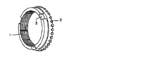
- Synchronizer rings are already well known and a schematic perspective view is shown in FIG. The inner surface 1 of the synchronizer ring is subjected to synchronous sliding with a rotating tapered cone under high surface pressure and intermittent surface contact when the synchronizer ring is detached therefrom.
- a key groove 3 into which a key is fitted is formed on the outer peripheral surface of the synchronizer ring, and chamfers 2 are provided at predetermined intervals along the outer edge of the synchronizer ring.
- This chamfer has a structure that engages with a hub sleeve as a counterpart member.
- Patent Document 1 Zn: 20 to 40% by weight, Al: 2 to 11% by weight, one or more of Fe, Ni, and Co: 1 to 5% by weight, Ti: 0.1 to 4% by weight
- Patent Document 2 Zn: 28 to 34%, Al: 1.5 to 4%, Mn: 2 to 4.5%, Si: 0.5 to 2%, Cr: 0.005% by mass.
- a Cu alloy synchronizer ring having a composition containing 05-0.5%, Ni: 0.2-0.6%, Fe: 0.02-0.5%, and the remainder consisting of Cu and inevitable impurities
- the ⁇ -phase substrate shown in the Cu-Zn phase diagram is uniformly dispersed with relatively coarse crystallized crystals and ultrafine precipitates composed of intermetallic compounds.
- the ⁇ phase shown in FIG. Forms coarse crystallized products and ultrafine precipitates, resulting in fatigue It has been proposed to improve strength and wear resistance.
- Patent Document 3 Zn: 27-33%, Al: 3-4.5%, Ni: 1.5-3%, Ti: 1-2%, Mn: 0.2-% by mass.
- a Cu alloy synchronizer ring having a composition containing 0.7%, Fe: 0.05 to 0.5%, Si: 0.01 to 0.1%, and the balance consisting of Cu and inevitable impurities,
- the ⁇ -phase substrate shown in the Zn-based phase diagram is uniformly dispersed with relatively coarse crystallized crystals and ultrafine precipitates composed of intermetallic compounds.
- the fatigue strength of the chamfer part of the synchronizer ring is increased, and by containing a predetermined amount of Ni, Ti, and Fe, an intermetallic compound Forms coarse crystallized material and ultrafine precipitates, resulting in fatigue strength It has been proposed to improve the degree and wear resistance.
- Patent Document 4 Cu: 62.5 to 67.5%, Al: 4.5 to 5.5%, Ni: 2.7 to 3.7%, Ti: 1.0 to 2.0 %, Mn: 0.05 to 0.35%, and in a Cu alloy synchronizer ring having a composition consisting of Zn and inevitable impurities, the formula: ⁇ ZN + 6 ⁇ ( Al-0.9) ⁇ / ⁇ Cu-1.3 + ZN + 6 ⁇ (Al-0.9) ⁇ has a zinc equivalent within the range of 0.4 to 0.46, and the base structure is Cu : ⁇ -phase containing 65 to 74%, Al: 2.5 to 4.5%, Ni: 0.5 to 2.5%, Ti: 0.05 to 0.6%, Cu: 62 to 71 %, Al: 3.5 to 6.0%, Ni: 0.3 to 2.3%, Ti: 0.05 to 0.6% ⁇ 'phase two-phase structure It has been proposed to improve the plastic flow resistance when used in a highly exothermic environment.
- a Cu alloy synchronizer ring normally melts a molten Cu alloy so as to have a predetermined composition, casts the obtained molten metal into a mold to produce a billet of a predetermined size, and hot extrudes the billet.
- a Cu alloy pipe is manufactured, and then the pipe is manufactured to have a predetermined width (height).
- the main focus is on improving strength, toughness, wear resistance, fatigue resistance, etc. in order to meet the demands from the usage environment.
- the wear resistance is improved by dispersing intermetallic compounds in the substrate.
- the present invention provides a Cu alloy having excellent machinability as one aspect thereof, and is in mass%, Zn: 25% to 43%, Al: 2.0% or more. 8.0% or less, Ti: 0.10% to 5.0%, Cr: 0.010% to 0.040%, C: 0.0005% to 0.010%, Fe, Ni and Co One or two or more selected from among these are contained in a total of 1.0% or more and 5.0% or less, and the composition is composed of the remaining Cu and inevitable impurities.
- the Al content is more preferably 2.0% to 6.0%
- the Ti content is more preferably 0.10% to 2.0%.
- Another aspect of the present invention is an extruded pipe member that is made of the above-described Cu alloy.
- Another aspect of the present invention is a synchronizer ring, which is made of the above-described Cu alloy.
- the Cu alloy according to the present invention has the above-described composition, thereby reducing the amount of intermetallic compound that lowers the machinability, while fine carbides are dispersed in the substrate by Cr and C as trace components.
- the strength, toughness and wear resistance of the Cu alloy are ensured, it has strength, toughness and wear resistance comparable to those of conventional Cu alloys, and excellent machining compared to conventional Cu alloys. Have sex.
- a synchronizer ring having a higher processing efficiency than conventional and having high strength, toughness and wear resistance required as a synchronizer ring is Obtainable.
- the Cu alloy of the present invention has a composition comprising the following elements.
- the Zn component in the Cu alloy of the present invention has the effect of improving the strength, toughness and wear resistance of the Cu alloy by coexisting with Al.
- the Zn content is less than 25% by mass (hereinafter simply referred to as “%”)
- the area ratio of the ⁇ phase occupying the substrate decreases and the area ratio of the ⁇ phase increases, so the hardness decreases.
- the desired wear resistance cannot be ensured.
- the Zn content exceeds 43%, the wear resistance is improved, but the strength, toughness, and hot workability of the Cu alloy tend to decrease due to the appearance of the ⁇ phase. Therefore, the Zn content is 25 to 43%.
- the Al component improves the strength, toughness and wear resistance of the Cu alloy by coexistence with Zn.
- Al is one or two selected from Fe, Ni and Co.
- 2.0% or more of Al is contained.
- the amount is from 2.0 to 8.0%.
- the amount of intermetallic compound produced is reduced, so the upper limit of the Al content is 6.0%, and the Al content is reduced. It is more desirable to set it to 2.0 to 6.0%.
- Ti, Fe, Ni and Co When Ti component coexists with one or two or more iron group component elements selected from Al and Fe, Ni and Co, a fine granular intermetallic compound is formed at the time of solidification, and this refines the structure. At the same time, it has the effect of improving the wear resistance by being dispersed in the substrate. However, if the Ti content is less than 0.10% or the total content of Fe, Ni and Co is less than 1.0%, the effect of refining the structure and the effect of improving wear resistance are reduced, which is not preferable. On the other hand, when the Ti content exceeds 5.0%, or when the total content of Fe, Ni and Co exceeds 5.0%, the toughness of the Cu alloy is lowered, which is not preferable.
- the Ti content is 0.10 to 5.0%, and the total content of one or more iron group elements selected from Fe, Ni and Co is 1.0 to 5.0%.
- the upper limit of the Ti content is 2.0%, and the Ti content is 0.10 to 2%. It is more desirable to set it to 0.0%.
- Ni has a great effect of contributing to the above-described finer structure and improved wear resistance. Therefore, it is more desirable to add Ni as an essential addition, and the lower limit value of Ni in that case may be 1.5%.
- Cr dissolves in the Cu alloy substrate, increases the strength of the substrate by solid solution strengthening, and complements the decrease in strength and wear resistance of the Cu alloy accompanying the decrease in the amount of intermetallic compound produced.
- the Cr content is 0.010% or more and 0.040% or less.
- Mn 2% or more and 4.5% or less and Si: 0.5% or more and 2% or less are added, and Cr is added 0.05% or more and 0% or less.
- Patent Document 2 Although it is proposed to add 5% or less, the addition of Cr (and Mn, Si) in Patent Document 2 aims to improve wear resistance by forming an intermetallic compound in the alloy.
- the present invention which aims to reduce the formation of intermetallic compounds, is the purpose of adding Cr, and the action of Cr in a Cu alloy (improvement of wear resistance by solid solution strengthening and precipitation / dispersion of carbides) ) Is clearly different.
- C in the Cu alloy mainly reacts with component elements such as Ti and Cr to form carbides and is finely distributed in the substrate, thereby increasing the strength and hardness of the Cu alloy and improving wear resistance. At the same time, machinability is improved. However, if the content is less than 0.0005%, carbides are not formed enough to improve wear resistance. On the other hand, if the content exceeds 0.010%, the amount of carbide formed is excessive, and the strength and machinability both decrease due to coarsening of the carbide. Therefore, the C content is set to 0.0005% to 0.010%.
- the reason for limiting the numerical range of the composition of the Cu alloy of the present invention is as described above.
- the Vickers hardness HV is A high hardness of 200 or more is obtained, and excellent wear characteristics are exhibited.
- excellent machinability is achieved in which the number of cuts by the carbide tool for parting is 3000 or more.
- Al 2.0% to 6.0% and Ti: 0.10% More preferably, it is 2.0% or less.
- the contents of Al, Ti, and Cr be in a range that satisfies the formula of (Al + Ti + 3Cr) ⁇ 8.1%.
- the contents of Al and Ti are made as much as possible. This is because the production of intermetallic compounds that deteriorate the machinability is suppressed.
- the Vickers hardness HV is 200 or more, and in addition to having high hardness and wear resistance, carbide for parting off
- the machinability of 3200 or more processed by a bite is further improved (refer to the numerical values of the processed numbers of the present inventions 4 to 12 in Table 3 in Examples below).
- a Cu alloy having the predetermined composition is melted by a high-frequency melting furnace, an ingot is manufactured by die casting, and the ingot is hot forged.
- an extruded pipe member made of a Cu alloy having a predetermined size is produced by hot extrusion.
- the Cu alloy extruded pipe member is cut so as to have a predetermined width (height), thereby obtaining a Cu alloy synchronizer ring (material) made of a Cu alloy having a predetermined composition. be able to.
- the Cu alloy melt of the present invention was melted so as to have the composition shown in Table 1 with a normal high-frequency melting furnace.
- the obtained molten metal was cast into a mold having a casting temperature of 1,100 ° C. and an inner diameter of 250 mm to produce a Cu alloy ingot having a diameter of 250 mm and a length of 3000 mm.
- this ingot was cut into a predetermined length and subjected to hot extrusion at 750 ° C. to produce a Cu alloy extruded pipe having an outer diameter of 72 mm and an inner diameter of 54 mm.
- this pipe was subjected to parting with a width of 10 mm using a carbide tool for parting (model: JIS21 type, carbide tip: ISO M20) to produce the present invention rings 1 to 12 having a height of 10 mm. Further, by cutting the inner and outer diameters of the rings 1 to 12 of the present invention, a Cu alloy synchronizer ring having an outer diameter of 70 mm, an inner diameter of 56 mm, and a height of 10 mm was produced.
- Comparative Rings 1 to 6 are manufactured in the same process as in the above embodiment, and further, by cutting the inner and outer diameters, a Cu alloy having an outer diameter of 70 mm, an inner diameter of 56 mm, and a height of 10 mm. A synchronizer ring was produced.
- the rings 1 to 12 of the present invention and the comparative rings 1 to 6 per one piece of the carbide tool for parting off are used.
- the machinability of the Cu alloy of the present invention and the comparative example Cu alloy was evaluated based on the size of the machined number.
- the cross section of the produced rings of the present invention 1 to 12 and comparative rings 1 to 6 having a height of 10 mm was subjected to a Vickers hardness test (load: 10 kg), and the present invention was determined by the magnitude of the Vickers hardness HV.
- the wear resistance of the rings 1 to 12 and the comparative rings 1 to 6 was evaluated. Table 3 shows these results.
- the Cu alloy of the present invention and the synchronizer ring produced therefrom have excellent wear resistance due to the high Vickers hardness HV of 204 to 223, and one bite.
- the machinability evaluated by the number of cut-off processes per hit is 3004 to 3702 (pieces), which is excellent in machinability, and it can be seen that the machinability is excellent in balance between wear resistance and machinability.
- the conditions in which the Al content is 2.0% or more and 6.0% or less and the Ti content is 0.10% or more and 2.0% or less, or the respective contents of Al, Ti, and Cr are (Al + Ti + 3Cr).
- the hardness is slightly inferior to the present inventions 1 to 3 (HV: 204 to 214), but excellent. Machinability (number of processed parts: 3283 to 3702) is provided.
- Comparative Examples 1 to 3 that deviate from the composition defined in the present invention have excellent machinability (number of parting off processes 3744 to 3792 (pieces)), but the Vickers hardness HV value is as small as 172 to 192. Inferior in wear resistance.
- Comparative Examples 4 to 6 (HV: 238 to 258) having high Vickers hardness were inferior in machinability because the number of parting off was as small as 2342 to 2542 (pieces).
- the comparative Cu alloy does not have both wear resistance and machinability, while the Cu alloy of the present invention has excellent wear resistance and excellent machinability. Since it has both characteristics, it is a suitable material as a Cu alloy for producing a synchronizer ring.
- the Cu alloy of the present invention is excellent in machinability and wear resistance, it is a suitable material for a synchronizer ring.
- the present invention is not limited to this application, and is an excellent machine. A wide range of applications and developments are possible in various technical fields that require machinability as well as mechanical characteristics.
Landscapes
- Chemical & Material Sciences (AREA)
- Engineering & Computer Science (AREA)
- Materials Engineering (AREA)
- Mechanical Engineering (AREA)
- Metallurgy (AREA)
- Organic Chemistry (AREA)
- Mechanical Operated Clutches (AREA)
Abstract
すぐれた被削性を備えるCu合金およびこれからなるCu合金製押出しパイプ部材、Cu合金製シンクロナイザーリングを提供する。質量%で、Zn:25%以上43%以下、Al:2.0%以上8.0%以下、Ti:0.10%以上5.0%以下、Cr:0.010%以上0.040%以下、C:0.0005%以上0.010%以下、Fe、NiおよびCoの内から選ばれる1種または2種以上を合計で1.0%以上5.0%以下含有し、残部Cuおよび不可避不純物からなり、金属間化合物の生成量を低減し、素地中に微細炭化物を分散させた被削性に優れたCu合金、および、これからなるCu合金製押出しパイプ部材、Cu合金製シンクロナイザーリング。
Description
この発明は、すぐれた機械的性質と耐摩耗性とを備え、かつ、被削性にも優れたCu合金に関し、特に、自動車のマニュアルトランスミッション用部品であるシンクロナイザーリングとして好適なCu合金およびこのCu合金製の押出しパイプ部材およびシンクロナイザーリングに関するものである。
銅合金は、従来から、そのすぐれた強度、熱伝導性、導電性、耐食性、耐摩耗性等を生かし、幅広い分野で利用されている。特に、自動車部品用の用途としては、銅合金は、例えば、マニュアルトランスミッション用のシンクロナイザーリングとして利用されている。
シンクロナイザーリングは、既によく知られており、図1にその概略斜視図を示す。シンクロナイザーリングの内面1は、回転するテーパーコーンとの高面圧下での同期摺動並びにこれより離脱する際の断続的面接触を受ける。また、シンクロナイザーリングの外周面には、キーが嵌合するキー溝3が形成され、さらに、シンクロナイザーリングの外縁にそって所定間隔おきにチャンファー2が設けられている。このチャンファーは相手部材であるハブスリーブとかみ合う構造をもつものである。
このようなCu合金製シンクロナイザーリングについて、使用条件の高負荷化に伴い、その耐摩耗性とともに、強度、靱性、耐疲労特性等を改善すべく、種々の提案がなされている。
シンクロナイザーリングは、既によく知られており、図1にその概略斜視図を示す。シンクロナイザーリングの内面1は、回転するテーパーコーンとの高面圧下での同期摺動並びにこれより離脱する際の断続的面接触を受ける。また、シンクロナイザーリングの外周面には、キーが嵌合するキー溝3が形成され、さらに、シンクロナイザーリングの外縁にそって所定間隔おきにチャンファー2が設けられている。このチャンファーは相手部材であるハブスリーブとかみ合う構造をもつものである。
このようなCu合金製シンクロナイザーリングについて、使用条件の高負荷化に伴い、その耐摩耗性とともに、強度、靱性、耐疲労特性等を改善すべく、種々の提案がなされている。
例えば、特許文献1には、Zn:20~40重量%、Al:2~11重量%、Fe、Ni、Coのうち1種以上:1~5重量%、Ti:0.1~4重量%を含有し、残りがCuおよび不可避不純物からなる銅合金製シンクロナイザーリングの組成に、さらに、Mn:0.01~0.1重量%未満、S:0.0005~0.01重量%のうちの一方または双方を含有させることにより、従来のCu合金製シンクロナイザーリングよりも耐摩耗性を向上させることが提案されている。
また、特許文献2には、質量%で、Zn:28~34%、Al:1.5~4%、Mn:2~4.5%、Si:0.5~2%、Cr:0.05~0.5%、Ni:0.2~0.6%、Fe:0.02~0.5%を含有し、残りがCuと不可避不純物からなる組成のCu合金製シンクロナイザーリングにおいて、Cu-Zn系状態図で示されるβ相の素地に、いずれも金属間化合物で構成された相対的に粒径の粗い晶出物と超微細な析出物を均一分散させ、さらに、同状態図で示されるα相が針状形状で分散分布した組織を形成することにより、シンクロナイザーリングのチャンファー部の疲労強度を高めるとともに、所定量のMn、SiおよびCrを含有することによって、金属間化合物からなる粗粒の晶出物と超微細な析出物を形成し、疲労強度および耐摩耗性を向上させることが提案されている。
また、特許文献3には、質量%で、Zn:27~33%、Al:3~4.5%、Ni:1.5~3%、Ti:1~2%、Mn:0.2~0.7%、Fe:0.05~0.5%、Si:0.01~0.1%を含有し、残りがCuと不可避不純物からなる組成のCu合金製シンクロナイザーリングにおいて、Cu-Zn系状態図で示されるβ相の素地に、いずれも金属間化合物で構成された相対的に粒径の粗い晶出物と超微細な析出物を均一分散させ、さらに、同状態図に示されるα相が針状形状で分散分布した組織を形成することにより、シンクロナイザーリングのチャンファー部の疲労強度を高めるとともに、所定量のNi、Ti、およびFeを含有することによって、金属間化合物からなる粗粒の晶出物と超微細な析出物を形成し、疲労強度および耐摩耗性を向上させることが提案されている。
さらに、特許文献4には、Cu:62.5~67.5%、Al:4.5~5.5%、Ni:2.7~3.7%、Ti:1.0~2.0%、Mn:0.05~0.35%を含有し、残りがZnおよび不可避不純物からなる組成を有するCu合金製シンクロナイザーリングにおいて、Zn+不可避不純物=ZNとしたとき、式:{ZN+6×(Al-0.9)}/{Cu-1.3+ZN+6×(Al-0.9)}で表される亜鉛当量が0.4~0.46の範囲内に有り、かつ、素地組織を、Cu:65~74%、Al:2.5~4.5%、Ni:0.5~2.5%、Ti:0.05~0.6%を含有するα相と、Cu:62~71%、Al:3.5~6.0%、Ni:0.3~2.3%、Ti:0.05~0.6%を含有するβ´相の2相組織として構成することにより、高発熱環境下での使用における耐塑性流動性を改善することが提案されている。
Cu合金製シンクロナイザーリングは、通常、所定の組成となるようにCu合金溶湯を溶製し、得られた溶湯をモールドに鋳込んで所定サイズのビレットを製造し、このビレットを熱間押出しすることによってCu合金製パイプを作製し、ついで、このパイプを所定幅(高さ)になるように切削加工することによって作製している。
前記特許文献1~4に示されるCu合金製シンクロナイザーリングにおいては、使用環境からの要請に応えるため、主として、強度、靱性、耐摩耗性、耐疲労特性等の改善に重点が置かれており、特に、金属間化合物を素地に分散させることによって耐摩耗性の向上が図られている。
しかし、金属間化合物が素地に分散分布している組織の場合には、確かに耐摩耗性は高められるものの、その反面、前述したCu合金製シンクロナイザーリングの作製工程において切削加工する際に、硬質の金属間化合物の存在によって被削性が劣り、加工能率が低下するという問題があった。
そこで、Cu合金製シンクロナイザーリングとして必要とされる特性、即ち、強度、靱性、耐摩耗性等を備えるとともに、これに加え、被削性にも優れるCu合金の開発が望まれている。
前記特許文献1~4に示されるCu合金製シンクロナイザーリングにおいては、使用環境からの要請に応えるため、主として、強度、靱性、耐摩耗性、耐疲労特性等の改善に重点が置かれており、特に、金属間化合物を素地に分散させることによって耐摩耗性の向上が図られている。
しかし、金属間化合物が素地に分散分布している組織の場合には、確かに耐摩耗性は高められるものの、その反面、前述したCu合金製シンクロナイザーリングの作製工程において切削加工する際に、硬質の金属間化合物の存在によって被削性が劣り、加工能率が低下するという問題があった。
そこで、Cu合金製シンクロナイザーリングとして必要とされる特性、即ち、強度、靱性、耐摩耗性等を備えるとともに、これに加え、被削性にも優れるCu合金の開発が望まれている。
そこで本発明は、前記課題を解決するために、その一態様として、被削性に優れたCu合金であって、質量%で、Zn:25%以上43%以下、Al:2.0%以上8.0%以下、Ti:0.10%以上5.0%以下、Cr:0.010%以上0.040%以下、C:0.0005%以上0.010%以下、Fe、NiおよびCoの内から選ばれる1種または2種以上を合計で1.0%以上5.0%以下含有し、残部Cuおよび不可避不純物からなる組成を有するものである。
このCu合金の組成において、Alの含有量は2.0%以上6.0%以下、Tiの含有量は0.10%以上2.0%以下とすることがより好ましい。又は、このCu合金の組成において、AlとTiとCrのそれぞれの含有量が、(Al+Ti+3Cr)≦8.1%の式を満足することがより好ましい。
このCu合金の組成において、Alの含有量は2.0%以上6.0%以下、Tiの含有量は0.10%以上2.0%以下とすることがより好ましい。又は、このCu合金の組成において、AlとTiとCrのそれぞれの含有量が、(Al+Ti+3Cr)≦8.1%の式を満足することがより好ましい。
本発明は、別の態様として、押出しパイプ部材であって、上述したCu合金からなるものである。
本発明は、また別の態様として、シンクロナイザーリングであって、上述したCu合金からなるものである。
本発明は、また別の態様として、シンクロナイザーリングであって、上述したCu合金からなるものである。
本発明に係るCu合金は、上述した組成としたことで、被削性を低下させる金属間化合物の生成量が低減し、その一方、微量含有成分であるCr、Cによって微細炭化物が素地に分散し、Cu合金の強度、靱性および耐摩耗性を担保していることから、従来のCu合金に匹敵する強度、靱性、耐摩耗性を有するとともに、従来のCu合金に比してすぐれた被削性を備える。
また、本発明に係るCu合金を用いてシンクロナイザーリングを作製するに際し、従来よりも高い加工能率で、しかも、シンクロナイザーリングとして求められる高強度、靱性、耐摩耗性を備えたシンクロナイザーリングを得ることができる。
本発明に係るCu合金、押出しパイプ部材およびシンクロナイザーリングの各実施の形態について、以下に、詳細に説明する。本発明のCu合金は、以下の元素からなる組成を有するものである。
Zn:
本発明のCu合金中のZn成分には、Alと共存することによってCu合金の強度、靭性および耐摩耗性を向上させる作用がある。但し、Znの含有量が25質量%(以下、単に「%」と記す)未満になると、素地に占めるβ相の面積割合が減少し、α相の面積割合が増加するため、硬さが低下し、所望の耐摩耗性を確保することができない。
一方、Znの含有量が43%を超えると、耐摩耗性は向上するものの、γ相の出現によってCu合金の強度、靭性、熱間加工性が低下傾向を示すようになる。
したがって、Znの含有量は、25~43%とする。
本発明のCu合金中のZn成分には、Alと共存することによってCu合金の強度、靭性および耐摩耗性を向上させる作用がある。但し、Znの含有量が25質量%(以下、単に「%」と記す)未満になると、素地に占めるβ相の面積割合が減少し、α相の面積割合が増加するため、硬さが低下し、所望の耐摩耗性を確保することができない。
一方、Znの含有量が43%を超えると、耐摩耗性は向上するものの、γ相の出現によってCu合金の強度、靭性、熱間加工性が低下傾向を示すようになる。
したがって、Znの含有量は、25~43%とする。
Al:
Al成分はZnとの共存によって、Cu合金の強度、靭性および耐摩耗性を向上させることは前記のとおりであり、さらに、Alは、Fe、NiおよびCoの内から選ばれる1種または2種以上の鉄族元素およびTiとの金属間化合物を形成して、耐摩耗性を向上させることから、Alを2.0%以上含有させる。一方、8.0%を超えて含有させても耐摩耗性向上効果は少なく、その反面、γ相の出現によりCu合金の靱性、熱間加工性を低下させるようになることから、Alの含有量は2.0~8.0%とする。
特に、本発明では、Cu合金の被削性を向上させるために、金属間化合物の生成量の低減を図っていることから、Al含有量の上限を6.0%とし、Alの含有量を2.0~6.0%とすることがより望ましい。
Al成分はZnとの共存によって、Cu合金の強度、靭性および耐摩耗性を向上させることは前記のとおりであり、さらに、Alは、Fe、NiおよびCoの内から選ばれる1種または2種以上の鉄族元素およびTiとの金属間化合物を形成して、耐摩耗性を向上させることから、Alを2.0%以上含有させる。一方、8.0%を超えて含有させても耐摩耗性向上効果は少なく、その反面、γ相の出現によりCu合金の靱性、熱間加工性を低下させるようになることから、Alの含有量は2.0~8.0%とする。
特に、本発明では、Cu合金の被削性を向上させるために、金属間化合物の生成量の低減を図っていることから、Al含有量の上限を6.0%とし、Alの含有量を2.0~6.0%とすることがより望ましい。
Ti、Fe、NiおよびCo:
Ti成分は、AlおよびFe、NiおよびCoの内から選ばれる1種または2種以上の鉄族成分元素と共存した場合、凝固時に微細粒状の金属間化合物を形成し、これが組織を微細化すると同時に、素地に分散して耐摩耗性を向上させる作用を有する。
しかし、Ti含有量が0.10%未満あるいはFe、NiおよびCoの含有量合計が1.0%未満では、組織の微細化効果、耐摩耗性向上効果が少なくなるので、好ましくない。一方、Ti含有量が5.0%を超える場合、あるいは、Fe、NiおよびCoの含有量合計が5.0%を超える場合には、Cu合金の靭性が低下するので、好ましくない。
したがって、Ti含有量は0.10~5.0%、また、Fe、NiおよびCoの内から選ばれる1種または2種以上の鉄族元素の合計含有量は1.0~5.0%とする。
特に、Cu合金中に生成する金属間化合物の生成量を低減し、被削性能を改善するという観点からは、Ti含有量は2.0%を上限とし、Ti含有量を0.10~2.0%とすることがより望ましい。なお、上記のFe、NiおよびCoのうち、とりわけNiは前述の組織微細化並びに耐摩耗性向上に寄与する効果が大きい。そのため、Niは必須添加とするのがより望ましく、その場合のNiの下限値は1.5%にすれば良い。
Ti成分は、AlおよびFe、NiおよびCoの内から選ばれる1種または2種以上の鉄族成分元素と共存した場合、凝固時に微細粒状の金属間化合物を形成し、これが組織を微細化すると同時に、素地に分散して耐摩耗性を向上させる作用を有する。
しかし、Ti含有量が0.10%未満あるいはFe、NiおよびCoの含有量合計が1.0%未満では、組織の微細化効果、耐摩耗性向上効果が少なくなるので、好ましくない。一方、Ti含有量が5.0%を超える場合、あるいは、Fe、NiおよびCoの含有量合計が5.0%を超える場合には、Cu合金の靭性が低下するので、好ましくない。
したがって、Ti含有量は0.10~5.0%、また、Fe、NiおよびCoの内から選ばれる1種または2種以上の鉄族元素の合計含有量は1.0~5.0%とする。
特に、Cu合金中に生成する金属間化合物の生成量を低減し、被削性能を改善するという観点からは、Ti含有量は2.0%を上限とし、Ti含有量を0.10~2.0%とすることがより望ましい。なお、上記のFe、NiおよびCoのうち、とりわけNiは前述の組織微細化並びに耐摩耗性向上に寄与する効果が大きい。そのため、Niは必須添加とするのがより望ましく、その場合のNiの下限値は1.5%にすれば良い。
Cr:
Crは、Cu合金素地に固溶し、固溶強化により素地の強度を高め、金属間化合物生成量の減少に伴うCu合金の強度低下、耐摩耗性の低下を補完する。但し、0.010%未満のCr含有量では、その効果が少ない。一方、Cr含有量が0.040%を超えると、金属間化合物として析出し、被削性を低下させるようになる。よって、Cr含有量は0.010%以上0.040%以下とする。
なお、前記特許文献2には、Cu合金中の合金成分として、Mn:2%以上4.5%以下及びSi:0.5%以上2%以下の添加とともに、Crを0.05%以上0.5%以下添加含有させることが提案されているが、特許文献2におけるCr(およびMn、Si)の添加は、合金中に金属間化合物を形成することによる耐摩耗性の向上を目的としているものであり、金属間化合物の生成の低減化を図る本発明とは、Crを添加する目的、およびCu合金中でCrが果たす作用(固溶強化と炭化物の析出・分散による耐摩耗性の向上)は明らかに異なる。
Crは、Cu合金素地に固溶し、固溶強化により素地の強度を高め、金属間化合物生成量の減少に伴うCu合金の強度低下、耐摩耗性の低下を補完する。但し、0.010%未満のCr含有量では、その効果が少ない。一方、Cr含有量が0.040%を超えると、金属間化合物として析出し、被削性を低下させるようになる。よって、Cr含有量は0.010%以上0.040%以下とする。
なお、前記特許文献2には、Cu合金中の合金成分として、Mn:2%以上4.5%以下及びSi:0.5%以上2%以下の添加とともに、Crを0.05%以上0.5%以下添加含有させることが提案されているが、特許文献2におけるCr(およびMn、Si)の添加は、合金中に金属間化合物を形成することによる耐摩耗性の向上を目的としているものであり、金属間化合物の生成の低減化を図る本発明とは、Crを添加する目的、およびCu合金中でCrが果たす作用(固溶強化と炭化物の析出・分散による耐摩耗性の向上)は明らかに異なる。
C:
Cu合金中のCは、主として、Ti、Cr等の成分元素と反応して炭化物を形成し、素地中に微細に分布することによりCu合金の強度、硬さを高め、耐摩耗性を向上させると同時に被削性を向上させる。
しかし、その含有量が0.0005%未満では、耐摩耗性を向上させるに十分なほど炭化物が形成されない。一方、その含有量が0.010%を超えると、形成される炭化物量が過剰になり、また、炭化物の粗大化により、強度、被削性がともに低下する。
したがって、C含有量は0.0005%~0.010%とする。
Cu合金中のCは、主として、Ti、Cr等の成分元素と反応して炭化物を形成し、素地中に微細に分布することによりCu合金の強度、硬さを高め、耐摩耗性を向上させると同時に被削性を向上させる。
しかし、その含有量が0.0005%未満では、耐摩耗性を向上させるに十分なほど炭化物が形成されない。一方、その含有量が0.010%を超えると、形成される炭化物量が過剰になり、また、炭化物の粗大化により、強度、被削性がともに低下する。
したがって、C含有量は0.0005%~0.010%とする。
本発明のCu合金の組成の数値範囲限定理由は前記のとおりであり、このような組成を有するCu合金製シンクロナイザーリングにおいては、後記する実施例でも明らかにするように、ビッカース硬さHVが200以上である高硬度が得られ、すぐれた摩耗性を示すと同時に、突切用超硬バイトによる加工個数が3000個以上であるすぐれた被削性をも示す。
また、耐摩耗性を低下させずに被削性を一段と向上させるという観点からは、Cu合金の組成において、Al:2.0%以上6.0%以下で、かつ、Ti:0.10%以上2.0%以下とすることがより望ましい。
あるいは、AlとTiとCrのそれぞれの含有量について、(Al+Ti+3Cr)≦8.1%の式を満足する範囲とすることがより望ましい。
これは、すでに述べたように、Cr及びCを合金成分として含有することによって、微細炭化物を形成させてCu合金の強度、耐摩耗性を確保し、その一方、AlとTiの含有量をできるだけ少なくして、被削性を劣化させる金属間化合物の生成を抑制するという理由による。
そして、被削性を一段と向上させた前記組成を有するCu合金製シンクロナイザーリングにおいては、ビッカース硬さHVが200以上であり、高硬度、耐摩耗性を備えることに加えて、突切用超硬バイトによる加工個数が3200個以上という被削性が一段とすぐれたものとなる(後記実施例の表3の本発明4~12の加工個数の数値参照)。
また、耐摩耗性を低下させずに被削性を一段と向上させるという観点からは、Cu合金の組成において、Al:2.0%以上6.0%以下で、かつ、Ti:0.10%以上2.0%以下とすることがより望ましい。
あるいは、AlとTiとCrのそれぞれの含有量について、(Al+Ti+3Cr)≦8.1%の式を満足する範囲とすることがより望ましい。
これは、すでに述べたように、Cr及びCを合金成分として含有することによって、微細炭化物を形成させてCu合金の強度、耐摩耗性を確保し、その一方、AlとTiの含有量をできるだけ少なくして、被削性を劣化させる金属間化合物の生成を抑制するという理由による。
そして、被削性を一段と向上させた前記組成を有するCu合金製シンクロナイザーリングにおいては、ビッカース硬さHVが200以上であり、高硬度、耐摩耗性を備えることに加えて、突切用超硬バイトによる加工個数が3200個以上という被削性が一段とすぐれたものとなる(後記実施例の表3の本発明4~12の加工個数の数値参照)。
本発明では、例えば、高周波溶解炉により前記所定の組成となるようなCu合金を溶製し、金型鋳造にてインゴットを製造し、このインゴットを熱間鍛造する。
次いで、熱間押出しにより所定の寸法のCu合金製押出しパイプ部材を作製する。
次いで、上記Cu合金製押出しパイプ部材を、所定の幅(高さ)になるように切削加工することによって、所定の組成のCu合金からなる所定サイズのCu合金製シンクロナイザーリング(素材)を得ることができる。
次いで、熱間押出しにより所定の寸法のCu合金製押出しパイプ部材を作製する。
次いで、上記Cu合金製押出しパイプ部材を、所定の幅(高さ)になるように切削加工することによって、所定の組成のCu合金からなる所定サイズのCu合金製シンクロナイザーリング(素材)を得ることができる。
先ず、通常の高周波溶解炉により、表1に示される組成となるように本発明Cu合金溶湯を溶製した。この得られた溶湯を、鋳込み温度:1,100℃で内径:250mmの金型に鋳込み、直径:250mm、長さ:3000mmのCu合金インゴットを製造した。
ついで、このインゴットを所定の長さに切断し、750℃で熱間押出し加工を行い、外径:72mm、内径:54mmのCu合金製押出しパイプを作製した。
ついで、このパイプを、突切用超硬バイト(型式:JIS21型、超硬チップ:ISO M20)を用いて幅10mmで突切加工を施して高さ10mmの本発明リング1~12を作製した。
さらに、前記本発明リング1~12に、内・外径の切削加工を施すことにより、外径:70mm、内径:56mm、高さ:10mmのCu合金製シンクロナイザーリングを作製した。
ついで、このインゴットを所定の長さに切断し、750℃で熱間押出し加工を行い、外径:72mm、内径:54mmのCu合金製押出しパイプを作製した。
ついで、このパイプを、突切用超硬バイト(型式:JIS21型、超硬チップ:ISO M20)を用いて幅10mmで突切加工を施して高さ10mmの本発明リング1~12を作製した。
さらに、前記本発明リング1~12に、内・外径の切削加工を施すことにより、外径:70mm、内径:56mm、高さ:10mmのCu合金製シンクロナイザーリングを作製した。
比較のため、通常の高周波溶解炉により、表2に示される組成となるように比較例Cu合金溶湯を溶製した。次いで、前記実施例と同様な工程で比較例リング1~6を作製し、さらに、内・外径の切削加工を施すことにより、外径:70mm、内径:56mm、高さ:10mmのCu合金製シンクロナイザーリングを作製した。
前記Cu合金製シンクロナイザーリングの作製工程において、それぞれのCu合金の被削性の良否を調べるために、前記突切用超硬バイト1個当たりの本発明リング1~12および比較例リング1~6の加工個数をカウントし、該加工個数の大小によって本発明Cu合金、比較例Cu合金の被削性の良否を評価した。
また、前記作製した高さ10mmの本発明リング1~12および比較例リング1~6の断面について、ビッカース硬さ試験(ただし、荷重:10kg)を行い、ビッカース硬さHVの大小によって、本発明リング1~12および比較例リング1~6の耐摩耗性の良否を評価した。
表3に、これらの結果を示す。
また、前記作製した高さ10mmの本発明リング1~12および比較例リング1~6の断面について、ビッカース硬さ試験(ただし、荷重:10kg)を行い、ビッカース硬さHVの大小によって、本発明リング1~12および比較例リング1~6の耐摩耗性の良否を評価した。
表3に、これらの結果を示す。

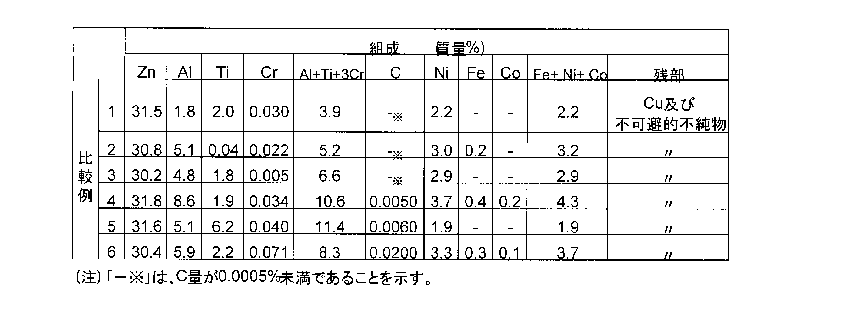
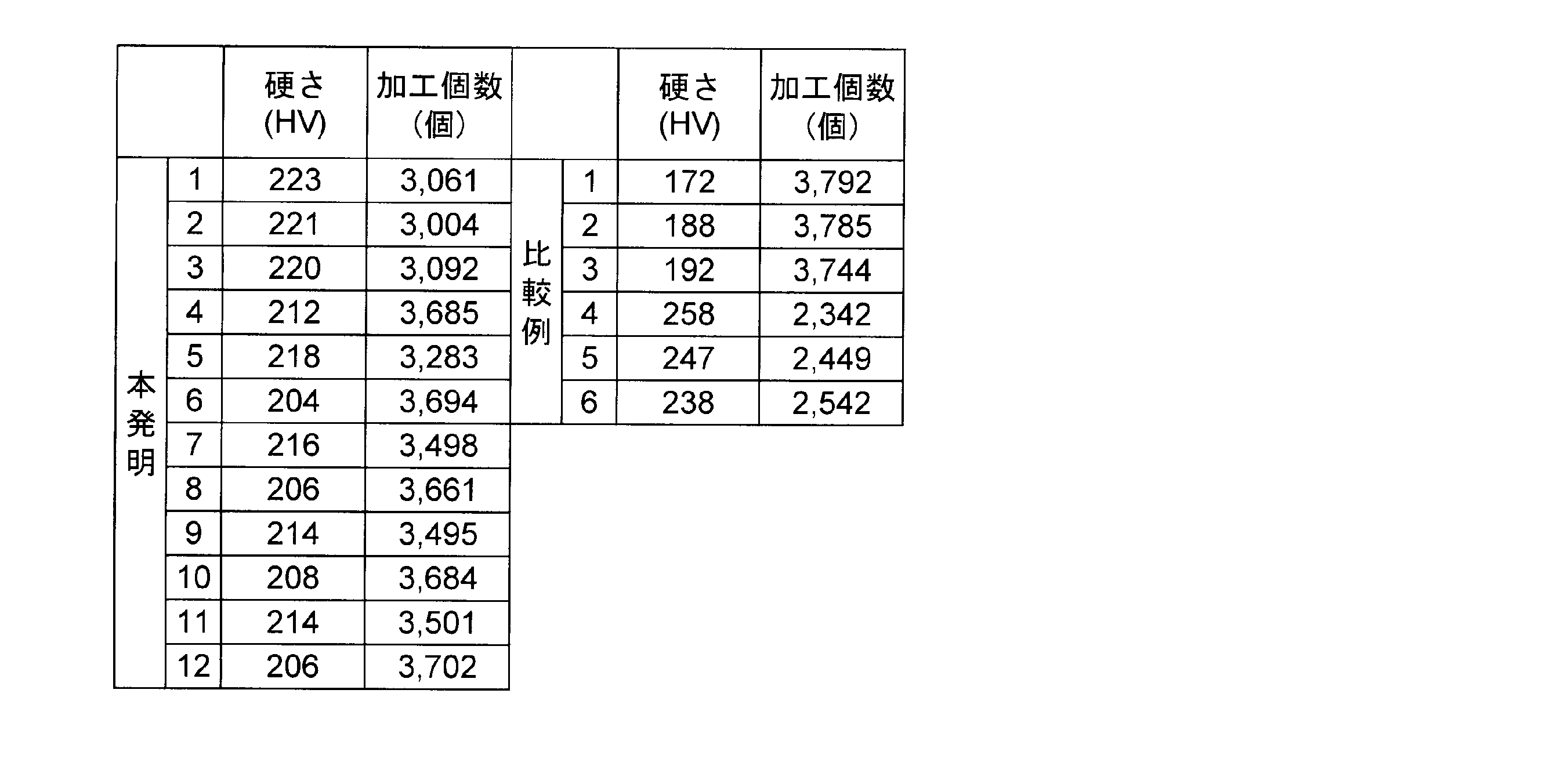
表3に示される結果から、本発明Cu合金およびこれから作製したシンクロナイザーリングは、ビッカース硬さHVは204~223という高硬度を有していることから耐摩耗性に優れ、さらに、バイト1個当たりの突切加工個数で評価した被削性は3004~3702(個)であって被削性にも優れており、耐摩耗性と被削性とのバランスに優れたものであることがわかる。
特に、Al含有量を2.0%以上6.0%以下、Ti含有量を0.10%以上2.0%以下とする条件、あるいはAlとTiとCrのそれぞれの含有量を、(Al+Ti+3Cr)≦8.1%の式を満たす範囲とする条件を満足する本発明4~12については、本発明1~3に比して硬さは若干劣る(HV:204~214)ものの、すぐれた被削性(加工個数:3283~3702)を備えている。
特に、Al含有量を2.0%以上6.0%以下、Ti含有量を0.10%以上2.0%以下とする条件、あるいはAlとTiとCrのそれぞれの含有量を、(Al+Ti+3Cr)≦8.1%の式を満たす範囲とする条件を満足する本発明4~12については、本発明1~3に比して硬さは若干劣る(HV:204~214)ものの、すぐれた被削性(加工個数:3283~3702)を備えている。
これに対して、本発明で定めた組成を外れる比較例1~3は、被削性に優れる(突切加工個数が3744~3792(個))もののビッカース硬度HVの値が172~192と小さいため耐摩耗性に劣った。一方、ビッカース硬さが高い比較例4~6(HV:238~258)では、突切加工個数が2342~2542(個)と小さいために被削性に劣った。
即ち、比較例のCu合金は、耐摩耗性と被削性の双方の特性を兼備するものではないのに対して、本発明のCu合金は、すぐれた耐摩耗性及びすぐれた被削性の双方の特性を相兼ね備えるものであるから、シンクロナイザーリング作製用のCu合金として好適な材料である。
以上説明したように、本発明のCu合金は被削性と耐摩耗性に優れていることから、シンクロナイザーリングとして好適な材料であるが、この用途に限定されるわけではなく、すぐれた機械的特性とともに、被削性の求められる各種技術分野への幅広い応用・展開が可能である。
1 シンクロナイザーリング内面
2 チャンファー
3 キー溝
2 チャンファー
3 キー溝
Claims (5)
- 質量%で、Zn:25%以上43%以下、Al:2.0%以上8.0%以下、Ti:0.10%以上5.0%以下、Cr:0.010%以上0.040%以下、C:0.0005%以上0.010%以下、Fe、NiおよびCoの内から選ばれる1種または2種以上を合計で1.0%以上5.0%以下含有し、残部Cuおよび不可避不純物からなる組成を有することを特徴とする被削性に優れたCu合金。
- 前記組成において、Alの含有量は2.0%以上6.0%以下、Tiの含有量は0.10%以上2.0%以下であることを特徴とする請求項1に記載の被削性に優れたCu合金。
- 前記組成において、AlとTiとCrのそれぞれの含有量が、(Al+Ti+3Cr)≦8.1%を満足することを特徴とする請求項1に記載の被削性に優れたCu合金。
- 請求項1乃至3のいずれか一項に記載のCu合金からなることを特徴とするCu合金製押出しパイプ部材。
- 請求項1乃至3のいずれか一項に記載のCu合金からなることを特徴とするCu合金製シンクロナイザーリング。
Priority Applications (2)
| Application Number | Priority Date | Filing Date | Title |
|---|---|---|---|
| PCT/JP2016/073995 WO2018033972A1 (ja) | 2016-08-17 | 2016-08-17 | 被削性に優れたCu合金、このCu合金製の押出しパイプ部材およびシンクロナイザーリング |
| CN201680088511.0A CN109642271B (zh) | 2016-08-17 | 2016-08-17 | 切削性优异的Cu合金、该Cu合金制的挤出管构件及同步器锁止环 |
Applications Claiming Priority (1)
| Application Number | Priority Date | Filing Date | Title |
|---|---|---|---|
| PCT/JP2016/073995 WO2018033972A1 (ja) | 2016-08-17 | 2016-08-17 | 被削性に優れたCu合金、このCu合金製の押出しパイプ部材およびシンクロナイザーリング |
Publications (1)
| Publication Number | Publication Date |
|---|---|
| WO2018033972A1 true WO2018033972A1 (ja) | 2018-02-22 |
Family
ID=61196547
Family Applications (1)
| Application Number | Title | Priority Date | Filing Date |
|---|---|---|---|
| PCT/JP2016/073995 Ceased WO2018033972A1 (ja) | 2016-08-17 | 2016-08-17 | 被削性に優れたCu合金、このCu合金製の押出しパイプ部材およびシンクロナイザーリング |
Country Status (2)
| Country | Link |
|---|---|
| CN (1) | CN109642271B (ja) |
| WO (1) | WO2018033972A1 (ja) |
Citations (3)
| Publication number | Priority date | Publication date | Assignee | Title |
|---|---|---|---|---|
| JPH0413825A (ja) * | 1990-05-07 | 1992-01-17 | Mitsubishi Materials Corp | 耐摩耗性Cu合金 |
| JPH07126778A (ja) * | 1993-11-05 | 1995-05-16 | Mitsubishi Materials Corp | 耐焼付性のすぐれた自動車変速機のCu合金製シンクロナイザリング材 |
| JPH07317804A (ja) * | 1994-05-25 | 1995-12-08 | Chuetsu Gokin Chuko Kk | シンクロナイザーリング |
Family Cites Families (2)
| Publication number | Priority date | Publication date | Assignee | Title |
|---|---|---|---|---|
| JPH08176706A (ja) * | 1994-12-26 | 1996-07-09 | Nippon Steel Corp | ガラス成形金型用材料 |
| KR100501619B1 (ko) * | 2003-03-31 | 2005-07-18 | 대창공업 주식회사 | 싱크로나이저링용 고강도 내마모성 동합금 및 그 제조방법 |
-
2016
- 2016-08-17 WO PCT/JP2016/073995 patent/WO2018033972A1/ja not_active Ceased
- 2016-08-17 CN CN201680088511.0A patent/CN109642271B/zh active Active
Patent Citations (3)
| Publication number | Priority date | Publication date | Assignee | Title |
|---|---|---|---|---|
| JPH0413825A (ja) * | 1990-05-07 | 1992-01-17 | Mitsubishi Materials Corp | 耐摩耗性Cu合金 |
| JPH07126778A (ja) * | 1993-11-05 | 1995-05-16 | Mitsubishi Materials Corp | 耐焼付性のすぐれた自動車変速機のCu合金製シンクロナイザリング材 |
| JPH07317804A (ja) * | 1994-05-25 | 1995-12-08 | Chuetsu Gokin Chuko Kk | シンクロナイザーリング |
Also Published As
| Publication number | Publication date |
|---|---|
| CN109642271A (zh) | 2019-04-16 |
| CN109642271B (zh) | 2021-01-29 |
Similar Documents
| Publication | Publication Date | Title |
|---|---|---|
| JP5454144B2 (ja) | 鋳造性に優れた無鉛快削性黄銅 | |
| CN100535144C (zh) | 含锡铜合金及其制造方法 | |
| JP5868510B2 (ja) | 快削性無鉛銅合金及びその製造方法 | |
| CN102016089B (zh) | 黄铜合金粉末、黄铜合金挤出材料及其制造方法 | |
| US8454766B2 (en) | Extruded material of a free-cutting aluminum alloy excellent in embrittlement resistance at a high temperature | |
| JP5546196B2 (ja) | 時効析出型銅合金、銅合金材料、銅合金部品および銅合金材料の製造方法 | |
| JP2018048397A (ja) | 耐食性に優れた黄銅 | |
| WO2010137483A1 (ja) | 機械的特性に優れた鋳物用無鉛銅合金 | |
| JP5403636B2 (ja) | 銅系摺動材料 | |
| JP2010242184A (ja) | 鋳造性及び耐食性に優れた無鉛快削性黄銅 | |
| JP2016151044A (ja) | 切削性に優れたアルミニウム合金押出材及びその製造方法 | |
| JP6179996B2 (ja) | 被削性に優れたCu合金、押出しパイプ部材およびCu合金製シンクロナイザーリング | |
| CN103789569B (zh) | 轴承保持架材料及其制造方法 | |
| TWI645053B (zh) | 黃銅合金熱加工品及黃銅合金熱加工品的製造方法 | |
| WO2018033972A1 (ja) | 被削性に優れたCu合金、このCu合金製の押出しパイプ部材およびシンクロナイザーリング | |
| JP5699774B2 (ja) | アルミニウム合金材及びその製造方法 | |
| JP2010031301A (ja) | Ni−Cr−Al合金素材 | |
| JP2008266719A (ja) | 快削アルミニウム合金押出し材 | |
| JP4337091B2 (ja) | 高発熱環境下で優れた耐塑性流動性を有する銅合金製シンクロナイザーリング | |
| KR101830841B1 (ko) | 고내마모성을 갖는 싱크로나이저 링용 동합금 및 이의 제조방법 | |
| JP2011038130A (ja) | 切削性および耐高温脆性に優れたアルミニウム合金 | |
| KR100501619B1 (ko) | 싱크로나이저링용 고강도 내마모성 동합금 및 그 제조방법 | |
| KR102666985B1 (ko) | 절삭성이 향상된 저실리콘 동합금 | |
| WO2016157413A1 (ja) | 水道部材用銅合金 | |
| WO2019193985A1 (ja) | 高温における機械的特性に優れた輸送機用圧縮機部品及びその製造方法 |
Legal Events
| Date | Code | Title | Description |
|---|---|---|---|
| 121 | Ep: the epo has been informed by wipo that ep was designated in this application |
Ref document number: 16913500 Country of ref document: EP Kind code of ref document: A1 |
|
| NENP | Non-entry into the national phase |
Ref country code: DE |
|
| NENP | Non-entry into the national phase |
Ref country code: JP |
|
| 122 | Ep: pct application non-entry in european phase |
Ref document number: 16913500 Country of ref document: EP Kind code of ref document: A1 |