WO2018025326A1 - アンワインダの制御装置 - Google Patents
アンワインダの制御装置 Download PDFInfo
- Publication number
- WO2018025326A1 WO2018025326A1 PCT/JP2016/072658 JP2016072658W WO2018025326A1 WO 2018025326 A1 WO2018025326 A1 WO 2018025326A1 JP 2016072658 W JP2016072658 W JP 2016072658W WO 2018025326 A1 WO2018025326 A1 WO 2018025326A1
- Authority
- WO
- WIPO (PCT)
- Prior art keywords
- unwinder
- tension
- control device
- sheet material
- reference value
- Prior art date
- Legal status (The legal status is an assumption and is not a legal conclusion. Google has not performed a legal analysis and makes no representation as to the accuracy of the status listed.)
- Ceased
Links
Images





Classifications
-
- B—PERFORMING OPERATIONS; TRANSPORTING
- B65—CONVEYING; PACKING; STORING; HANDLING THIN OR FILAMENTARY MATERIAL
- B65H—HANDLING THIN OR FILAMENTARY MATERIAL, e.g. SHEETS, WEBS, CABLES
- B65H23/00—Registering, tensioning, smoothing or guiding webs
- B65H23/04—Registering, tensioning, smoothing or guiding webs longitudinally
- B65H23/18—Registering, tensioning, smoothing or guiding webs longitudinally by controlling or regulating the web-advancing mechanism, e.g. mechanism acting on the running web
- B65H23/182—Registering, tensioning, smoothing or guiding webs longitudinally by controlling or regulating the web-advancing mechanism, e.g. mechanism acting on the running web in unwinding mechanisms or in connection with unwinding operations
- B65H23/185—Registering, tensioning, smoothing or guiding webs longitudinally by controlling or regulating the web-advancing mechanism, e.g. mechanism acting on the running web in unwinding mechanisms or in connection with unwinding operations motor-controlled
-
- B—PERFORMING OPERATIONS; TRANSPORTING
- B65—CONVEYING; PACKING; STORING; HANDLING THIN OR FILAMENTARY MATERIAL
- B65H—HANDLING THIN OR FILAMENTARY MATERIAL, e.g. SHEETS, WEBS, CABLES
- B65H2515/00—Physical entities not provided for in groups B65H2511/00 or B65H2513/00
- B65H2515/30—Forces; Stresses
- B65H2515/31—Tensile forces
- B65H2515/314—Tension profile, i.e. distribution of tension, e.g. across the material feeding direction or along diameter of web roll
-
- B—PERFORMING OPERATIONS; TRANSPORTING
- B65—CONVEYING; PACKING; STORING; HANDLING THIN OR FILAMENTARY MATERIAL
- B65H—HANDLING THIN OR FILAMENTARY MATERIAL, e.g. SHEETS, WEBS, CABLES
- B65H2557/00—Means for control not provided for in groups B65H2551/00 - B65H2555/00
- B65H2557/30—Control systems architecture or components, e.g. electronic or pneumatic modules; Details thereof
- B65H2557/32—Control systems architecture or components, e.g. electronic or pneumatic modules; Details thereof for modulating frequency or amplitude
Definitions
- This invention relates to a control device for an unwinder.
- Patent Document 1 discloses an unwinder control device. According to the control device, the tension acting on the sheet material can be kept constant based on the measured value of the diameter of the unwinder.
- An object of the present invention is to provide a control device for an unwinder that can maintain a constant tension acting on a sheet material without measuring the diameter of the unwinder.
- An unwinder control device in a winder facility including an unwinder that rewinds a sheet material and a winder that winds the sheet material, receives an input of a deviation between a tension reference value and a tension response value of the unwinder, A PI controller that calculates a candidate for the unwinder torque reference value by performing PI control on the deviation, and an input of the deviation between the tension reference value and the tension response value of the unwinder, and the sheet material wound around the unwinder In the sinusoidal transfer function having a resonance frequency corresponding to the frequency of the periodic disturbance due to the eccentricity, a compensation value with the deviation as an input is calculated, and the torque reference value candidate of the unwinder calculated by the PI controller is calculated. A model controller that adds the compensation value to obtain the unwinder torque reference value. .
- the unwinder torque reference value is calculated by adding the compensation value to the unwinder 1 torque reference value candidate calculated by the PI controller. For this reason, the tension
- seat material can be kept constant, without measuring the diameter of an unwinder.
- FIG. 1 It is a block diagram of the winder installation with which the control apparatus of the unwinder in Embodiment 1 of this invention is applied. It is a modeling figure of the unwinder eccentricity of the winder installation to which the control device of the unwinder in Embodiment 1 of this invention is applied. It is a block diagram for demonstrating tension control of the unwinder by the unwinder control apparatus in Embodiment 1 of this invention. It is a figure of the simulation result which shows the effectiveness of tension control by the control device of the unwinder in Embodiment 1 of this invention. It is a Bode diagram of a transfer function of a control device for an unwinder in Embodiment 1 of the present invention.
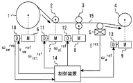
- FIG. 1 is a configuration diagram of a winder facility to which an unwinder control device according to Embodiment 1 of the present invention is applied.
- the unwinder 1 is provided at the uppermost stream of the winder equipment.
- the intermediate roll 2 is provided on the downstream side of the unwinder 1.
- the slitter 3 is provided on the downstream side of the intermediate roll 2.
- the winder 4 is provided on the downstream side of the slitter 3.
- the tensiometer 5 is provided between the slitter 3 and the winder 4.
- the unwinder driving motor 6 is provided corresponding to the unwinder 1.
- the intermediate roll driving motor 7 is provided corresponding to the intermediate roll 2.
- the slitter driving motor 8 is provided corresponding to the slitter 3.
- the winder driving motor 9 is provided corresponding to the winder 4.
- the unwinder drive device 10 is provided corresponding to the unwinder 1.
- the intermediate roll drive device 11 is provided corresponding to the intermediate roll 2.
- the slitter drive device 12 is provided corresponding to the slitter 3.
- the drive device 13 for driving the winder is provided corresponding to the winder 4.
- the input unit of the control device 14 is connected to the output unit of the tension meter 5.
- the input unit of the control device 14 is connected to the output unit of the unwinder drive device 10.
- the output unit of the control device 14 is connected to the input unit of the unwinder drive device 10.
- the output unit of the control device 14 is connected to the input unit of the intermediate roll drive device 11.
- the output unit of the control device 14 is connected to the input unit of the slitter drive device 12.
- the output unit of the control device 14 is connected to the input unit of the winder drive device 13.
- the sheet material 15 is wound around the unwinder 1 as a parent winding product.
- the sheet material 15 is paper.
- the sheet material 15 is a metal.
- the sheet material 15 is a film.
- the outer diameter of the sheet material 15 is large.
- the width of the sheet material 15 is wide.
- the sheet material 15 is heavy.
- the sheet material 15 is rewound from the unwinder 1.
- the sheet material 15 is cut to a preset winding width in the slitter 3 via the intermediate roll 2.
- the sheet material 15 is wound around the winder 4 so as to have a preset outer diameter. As a result, a small wound product is manufactured.
- the tension meter 5 detects the tension acting on the sheet material 15.
- the control device 14 receives an input of the tension response value T res (MPa) of the sheet material 15 from the tension meter 5.
- the control device 14 receives an input of the rotational speed response value ⁇ uw res (rad / s) of the unwinder 1 from the unwinder driving motor 6.
- the control device 14 outputs the torque reference value ⁇ uw ref (N ⁇ m) of the unwinder 1 to the drive device 10 for driving the unwinder.
- the unwinder drive device 10 controls the rotational speed of the unwinder drive motor 6 based on the torque reference value ⁇ uw ref (N ⁇ m).
- the control device 14 outputs the rotational speed reference value ⁇ int ref (rad / s) of the intermediate roll 2 to the intermediate roll drive device 11.
- the intermediate roll driving drive device 11 controls the rotational speed of the intermediate roll driving motor 7 based on the rotational speed reference value ⁇ int ref (rad / s).
- the control device 14 outputs the rotation speed reference value ⁇ sl ref (rad / s) of the slitter 3 to the slitter drive device 12.
- the slitter drive device 12 controls the rotation speed of the slitter drive motor 8 based on the rotation speed reference value ⁇ sl ref (rad / s).
- the control device 14 outputs the rotation speed reference value ⁇ w ref (rad / s) of the winder 4 to the winder drive device 13.
- the winder driving device 13 controls the rotational speed of the winder driving motor 9 based on the rotational speed reference value ⁇ w ref (rad / s).
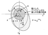
- FIG. 2 is a modeling diagram of the unwinder eccentricity of the winder facility to which the unwinder control apparatus according to Embodiment 1 of the present invention is applied.
- the horizontal axis in FIG. 2 is the x axis orthogonal to the rotation axis of the unwinder 1.
- the vertical axis in FIG. 2 is a y-axis orthogonal to the rotation axis of the unwinder 1 and the x-axis.
- A is the torque of the unwinder driving motor 6.
- the unit of A is N ⁇ m.
- B is a load torque.
- the unit of B is N ⁇ m.
- ⁇ is an angle corresponding to the position of the center of gravity of the eccentric unwinder 1.
- the unit of ⁇ is rad / s.
- r d is the radius of the unwinder 1 for the trajectory of the center of gravity of the unwinder 1 eccentric.
- Units of r d is in mm.
- m is the mass of the unwinder 1.
- the unit of m is kg.
- g is a gravitational acceleration.
- the unit of g is N / kg.
- the sheet material 15 is temporarily stored before being wound around the unwinder 1.
- the sheet material 15 is stored in a state of being wound around a winding core.
- the winding core is laid on a storage stand.
- the central portion of the sheet material 15 hangs down.
- the sheet material 15 is eccentric.
- the unwinder 1 is affected by the periodic disturbance torque ⁇ dis (N ⁇ m) due to the eccentric sheet material 15.
- the periodic disturbance torque ⁇ dis (N ⁇ m) is expressed by the following equation (1).
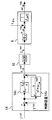
- FIG. 3 is a block diagram for explaining the unwinder tension control by the unwinder control apparatus according to Embodiment 1 of the present invention.
- the forward direction is set in a direction opposite to the winding direction of the sheet material 15 by the winder 4.
- control device 14 includes a PI controller 14a and a model controller 14b.
- the PI controller 14a receives an input of a deviation between the tension reference value T ref (Mpa) of the unwinder 1 and the tension response value T res (Mpa).
- the PI controller 14a calculates candidates for the torque reference value ⁇ uw ref (N ⁇ m) of the unwinder 1 by performing PI control on the deviation.
- the transfer function of the PI controller 14a is expressed by the following equation (2).
- Kp is a proportional gain.
- K I is an integral gain.
- s is a Laplace operator.
- the model controller 14b is applied in parallel to the PI controller 14a.
- the model controller 14b receives an input of a deviation between the tension reference value T ref (Mpa) and the tension response value T res (Mpa) of the unwinder 1.
- the model controller 14b obtains a compensation value obtained by inputting the deviation in a sine wave transfer function having a resonance frequency corresponding to the frequency of the periodic disturbance torque ⁇ dis (N ⁇ m) due to the eccentricity of the coil wound around the unwinder 1. calculate.
- the transfer function of the model controller 14b is expressed by a Laplace transform equation of the cos function. Specifically, the transfer function of the model controller 14b is expressed by the following equation (3).
- K s is a proportional gain.
- s is a Laplace operator.
- Model controller 14b a torque reference value calculated by the PI controller 14a tau uw ref torque reference value of the unwinder 1 by adding the compensation value to the candidate of the (N ⁇ m) ⁇ uw ref (N ⁇ m) And At this time, the resonance frequency is updated every sampling.
- the unwinder drive device 10 performs current control based on the torque reference value ⁇ uw ref (N ⁇ m). As a result, a Q-axis current response value I q res (A) is obtained.
- the unwinder driving motor 6 rotates based on the Q-axis current response value I q res (A). As a result, a torque response value ⁇ uw res (N ⁇ m) is obtained.
- the torque response value ⁇ uw res (N ⁇ M) is determined based on the d-axis magnetic flux ⁇ d (Wb) of the unwinder driving motor 6.
- the periodic disturbance torque ⁇ dis (N ⁇ m) is added to the torque response value ⁇ uw res (N ⁇ M).
- an actual rotational speed response value ⁇ uw res (rad / s) is obtained.
- the actual rotational speed response value ⁇ uw res (rad / s) includes the torque response value ⁇ uw res (N ⁇ M), the disturbance torque ⁇ dis (N ⁇ m), and the inertia moment J uw (kgm 2 ) of the unwinder 1. Determined by Laplace operator s.
- the tension response value T res (Mpa) of the unwinder 1 is obtained by time integration of the difference between the rotational speed response value ⁇ w res (rad / s) of the winder 4 and the rotational speed response value ⁇ uw res (rad / s) of the unwinder 1. It is proportional to the value.
- the tension response value T res (MPa) is expressed by the following equation (4).
- E is the Young's modulus of the sheet material 15.
- the unit of E is MPa.
- L is the distance between the unwinder 1 and the winder 4.
- the unit of L is mm.
- v w res is a peripheral speed response value of the winder 4.
- the unit of v w res is mm / s.
- v uw res is a peripheral speed response value of the unwinder 1.
- the unit of v uw res is mm / s.
- R w is the radius of the winder 4.
- Units of R w is in mm.
- R uw is the radius of the winder 4.
- the unit of R uw is mm.
- the periodic disturbance torque ⁇ dis (N ⁇ m) can change the rotational speed response value ⁇ uw res (rad / s).
- the tension response value T res (MPa) can vary.
- the torque reference value ⁇ uw ref (N ⁇ m) is compensated with a compensation value corresponding to the resonance frequency corresponding to the frequency of the periodic disturbance torque ⁇ dis (N ⁇ m). For this reason, the fluctuation
- FIG. 4 is a diagram of simulation results showing the effectiveness of tension control by the unwinder control apparatus according to Embodiment 1 of the present invention.
- the horizontal axis of FIG. 4 is time (s).
- the vertical axis in the upper part of FIG. 4 is the line speed (mpm).
- the vertical axis in the lower part of FIG. 4 is the tension response value (MPa).
- the line speed is accelerated from 0 mpm to 1200 mpm.
- the tension response value is affected by the eccentricity of the unwinder 1. As a result, the tension response value varies. At this time, the frequency of the periodic disturbance is a frequency corresponding to the rotational speed of the unwinder 1. For this reason, as the line speed increases, the frequency of fluctuation of the tension response value also increases.
- the gain of the model controller 14b becomes infinite at the frequency of the periodic disturbance.
- the performance of suppressing disturbance is improved at a periodic disturbance frequency.
- the tension response value is not easily affected by the eccentricity of the unwinder 1. As a result, fluctuations in the tension response value are suppressed.
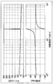
- FIG. 5 is a Bode diagram of a transfer function of the control device for the unwinder according to Embodiment 1 of the present invention.
- the horizontal axis in FIG. 5 represents the rotational speed of the unwinder 1.
- the vertical axis in the upper part of FIG. 5 is the gain (dB).
- the vertical axis in the lower part of FIG. 5 is the phase (deg) of the unwinder 1.
- the resonance frequency is set to 20 rad / s.
- the gain becomes infinite at 20 rad / s, which is the rotational speed corresponding to the resonance frequency.
- FIG. 6 is a flowchart for explaining the outline of the operation of the unwinder control apparatus according to Embodiment 1 of the present invention.
- step S1 the control device 14 determines whether or not the input of the tension reference value and the tension response value of the unwinder 1 has been received. When the control device 14 has not received the input of the tension reference value and the tension response value of the unwinder 1, the control device 14 repeats the operation of step S1. When the control device 14 receives the input of the tension reference value and the tension response value of the unwinder 1, the control device 14 performs the operation of step S2.
- step S2 the controller 14 calculates a candidate for the torque reference value of the unwinder 1 by performing PI control on the deviation between the tension reference value of the unwinder 1 and the tension response value. Thereafter, the control device 14 performs the operation of step S3.
- step S3 the control device 14 calculates a compensation value using the deviation as an input in a sine wave transfer function having a resonance frequency corresponding to the frequency of the periodic disturbance torque due to the eccentricity of the sheet material 15 wound around the unwinder 1. To do. Thereafter, the control device 14 performs the operation of step S4.
- step S4 the control device 14 sets the torque reference value of the unwinder 1 by adding the compensation value to the torque reference value candidate of the unwinder 1 calculated by the PI controller 14a. Thereafter, the control device 14 ends the operation.
- the torque reference value of the unwinder 1 is calculated by adding the compensation value to the torque reference value candidate of the unwinder 1 calculated by the PI controller 14a. For this reason, the tension acting on the sheet material 15 can be kept constant.
- FIG. 7 is a hardware configuration diagram of the unwinder control apparatus according to Embodiment 1 of the present invention.
- Each function of the control device 14 can be realized by a processing circuit.
- the processing circuit includes at least one processor 16a and at least one memory 16b.
- the processing circuit comprises at least one dedicated hardware 17.
- each function of the control device 14 is realized by software, firmware, or a combination of software and firmware. At least one of software and firmware is described as a program. At least one of software and firmware is stored in at least one memory 16b.
- the at least one processor 16a implements each function of the control device 14 by reading and executing a program stored in the at least one memory 16b.
- the at least one processor 16a is also referred to as a CPU (Central Processing Unit), a central processing unit, a processing unit, an arithmetic unit, a microprocessor, a microcomputer, and a DSP.
- the at least one memory 16b is a nonvolatile or volatile semiconductor memory such as RAM, ROM, flash memory, EPROM, or EEPROM, a magnetic disk, a flexible disk, an optical disk, a compact disk, a mini disk, a DVD, or the like.
- the processing circuit comprises at least one dedicated hardware 17, the processing circuit is implemented, for example, as a single circuit, a composite circuit, a programmed processor, a parallel programmed processor, an ASIC, an FPGA, or a combination thereof.
- each function of the control device 14 is realized by a processing circuit.
- each function of the control device 14 is collectively realized by a processing circuit.
- control device 14 may be realized by dedicated hardware 17, and the other part may be realized by software or firmware.
- the functions of the PI controller 14a are realized by a processing circuit as the dedicated hardware 17, and for functions other than the PI controller 14a, at least one processor 16a reads a program stored in at least one memory 16b. It may be realized by executing.
- the processing circuit realizes each function of the control device 14 by the hardware 17, software, firmware, or a combination thereof.
- FIG. FIG. 8 is a block diagram for explaining tension control by the unwinder control device according to Embodiment 2 of the present invention.
- symbol is attached
- the model controller 14b according to the second embodiment includes an adjustment parameter ⁇ .
- the transfer function of the model controller 14b of the second embodiment is expressed by the following equation (5).
- FIG. 9 is a diagram for explaining an adjustment parameter determination method by the unwinder control device according to the second embodiment of the present invention.
- the control device 14 includes an adjustment parameter determiner 14c.
- the adjustment parameter determiner 14c calculates the estimated rotational speed value ⁇ dis est (rad / s) corresponding to the disturbance frequency for each disturbance period T dis (s).
- the estimated rotational speed value ⁇ dis est (rad / s) is expressed by the following equation (6).
- f dis is the frequency of the disturbance.
- the unit of f dis is 1 / s.
- the adjustment parameter determiner 14c determines that the resonance frequency of the model controller 14b is a disturbance frequency based on the comparison result between the rotational speed estimation value ⁇ dis est (rad / s) and the rotational speed response value ⁇ uw res (rad / s).
- the adjustment parameter ⁇ is updated every disturbance period T dis (s) so as to coincide with.
- the adjustment parameter ⁇ is expressed by the following equation (7).
- FIG. 10 is a diagram for explaining a disturbance period measuring method by the unwinder control apparatus according to Embodiment 2 of the present invention.
- the horizontal axis of FIG. 10 is time (s).
- the vertical axis in FIG. 10 represents the tension response value (pu) from the tension meter 5 or the rotational speed response value (pu) from the speed meter that detects the rotational speed of the unwinder driving motor 6.
- T 1 , T 2, and T 3 are periods of adjacent peaks in the tension response value (pu) from the tensiometer 5 or the rotational speed response value (pu) from the speedometer.
- the adjustment parameter determiner 14c measures the period of the adjacent peak in the tension response value (pu) from the tensiometer 5 or the rotational speed response value (pu) from the speedometer as the disturbance period Tdis (s).
- the adjustment parameter determiner 14c measures the period of the adjacent peak in the tension response value (pu) from the tensiometer 5 or the rotational speed response value (pu) from the speedometer as the disturbance period Tdis (s).
- the resonance frequency of the model controller 14b is adjusted by the adjustment parameter ⁇ . For this reason, the tension acting on the sheet material 15 can be more reliably maintained constant.
- the adjustment parameter ⁇ is adjusted in real time based on the tension response value (pu) from the tension meter 5 or the rotational speed response value (pu) from the speedometer. Therefore, the adjustment parameter ⁇ can be easily adjusted.
- control device for an unwinder can be used for a system that maintains a constant tension acting on a sheet material.
Landscapes
- Controlling Rewinding, Feeding, Winding, Or Abnormalities Of Webs (AREA)
Abstract
Description
図1はこの発明の実施の形態1におけるアンワインダの制御装置が適用されるワインダ設備の構成図である。
図2はこの発明の実施の形態1におけるアンワインダの制御装置が適用されるワインダ設備のアンワインダの偏心のモデリング図である。図2の横軸は、アンワインダ1の回転軸に直交するx軸である。図2の縦軸は、アンワインダ1の回転軸とx軸とに直行するy軸である。

図3はこの発明の実施の形態1におけるアンワインダの制御装置よるアンワインダの張力制御を説明するためのブロック図である。図3において、正方向は、ワインダ4によるシート材15の巻取り方向とは反対方向に設定される。
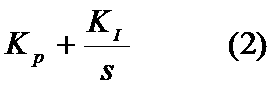


図4はこの発明の実施の形態1におけるアンワインダの制御装置による張力制御の有効性を示すシミュレーション結果の図である。図4の横軸は、時間(s)である。図4の上段の縦軸は、ライン速度(mpm)である。図4の下段の縦軸は、張力応答値(MPa)である。
図5はこの発明の実施の形態1におけるアンワインダの制御装置の伝達関数のボード線図である。図5の横軸は、アンワインダ1の回転速度である。図5の上段の縦軸は、ゲイン(dB)である。図5の下段の縦軸は、アンワインダ1の位相(deg)である。図5においては、共振周波数は、20rad/sに設定される。
図6はこの発明の実施の形態1におけるアンワインダの制御装置の動作の概要を説明するためのフローチャートである。
図7はこの発明の実施の形態1におけるアンワインダの制御装置のハードウェア構成図である。
図8はこの発明の実施の形態2におけるアンワインダの制御装置による張力制御を説明するためのブロック図である。なお、実施の形態1と同一または相当部分には、同一符号が付される。当該部分の説明は省略される。
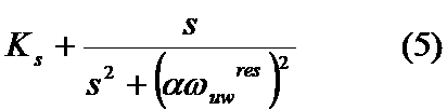
図9はこの発明の実施の形態2におけるアンワインダの制御装置による調整パラメータの決定方法を説明するための図である。
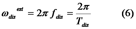
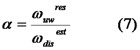
図10はこの発明の実施の形態2におけるアンワインダの制御装置による外乱の周期の計測方法を説明するための図である。図10の横軸は、時間(s)である。図10の縦軸は、張力計5からの張力応答値(pu)またはアンワインダ駆動用モータ6の回転速度を検出する速度計からの回転速度応答値(pu)である。
Claims (4)
- シート材を巻き戻すアンワインダとシート材を巻き取るワインダとを備えたワインダ設備において、前記アンワインダの張力基準値と張力応答値との偏差の入力を受け付け、当該偏差にPI制御を行うことにより前記アンワインダのトルク基準値の候補を算出するPI制御器と、
前記アンワインダの張力基準値と張力応答値との偏差の入力を受け付け、前記アンワインダに巻き付けられたシート材の偏心による周期的な外乱の周波数に対応した共振周波数を持つ正弦波伝達関数において当該偏差を入力とした補償値を算出し、前記PI制御器により算出された前記アンワインダのトルク基準値の候補に当該補償値を加算することで前記アンワインダのトルク基準値とするモデル制御器と、
を備えたアンワインダの制御装置。 - 前記モデル制御器は、前記正弦波伝達関数において共振周波数の調整パラメータを備え、当該調整パラメータを調整することにより周期的な外乱の周波数に共振周波数を一致させる請求項1に記載のアンワインダの制御装置。
- 前記モデル制御器は、シート材の張力を検出する張力計からの張力応答値に基づいて当該調整パラメータを調整することにより周期的な外乱の周波数に共振周波数を一致させる請求項2に記載のアンワインダの制御装置。
- 前記モデル制御器は、前記アンワインダを回転させるアンワインダ駆動用モータの回転速度を検出する速度計からの回転速度応答値に基づいて当該調整パラメータを調整することにより周期的な外乱の周波数に共振周波数を一致させる請求項2に記載のアンワインダの制御装置。
Priority Applications (4)
| Application Number | Priority Date | Filing Date | Title |
|---|---|---|---|
| KR1020187027337A KR102165597B1 (ko) | 2016-08-02 | 2016-08-02 | 언와인더의 제어 장치 |
| CN201680085175.4A CN109071140B (zh) | 2016-08-02 | 2016-08-02 | 退绕机的控制装置 |
| JP2018531013A JP6583559B2 (ja) | 2016-08-02 | 2016-08-02 | アンワインダの制御装置 |
| PCT/JP2016/072658 WO2018025326A1 (ja) | 2016-08-02 | 2016-08-02 | アンワインダの制御装置 |
Applications Claiming Priority (1)
| Application Number | Priority Date | Filing Date | Title |
|---|---|---|---|
| PCT/JP2016/072658 WO2018025326A1 (ja) | 2016-08-02 | 2016-08-02 | アンワインダの制御装置 |
Publications (1)
| Publication Number | Publication Date |
|---|---|
| WO2018025326A1 true WO2018025326A1 (ja) | 2018-02-08 |
Family
ID=61072943
Family Applications (1)
| Application Number | Title | Priority Date | Filing Date |
|---|---|---|---|
| PCT/JP2016/072658 Ceased WO2018025326A1 (ja) | 2016-08-02 | 2016-08-02 | アンワインダの制御装置 |
Country Status (4)
| Country | Link |
|---|---|
| JP (1) | JP6583559B2 (ja) |
| KR (1) | KR102165597B1 (ja) |
| CN (1) | CN109071140B (ja) |
| WO (1) | WO2018025326A1 (ja) |
Cited By (3)
| Publication number | Priority date | Publication date | Assignee | Title |
|---|---|---|---|---|
| CN114104856A (zh) * | 2021-12-28 | 2022-03-01 | 天津工业大学 | 基于机器视觉的纱线张力非接触实时检测控制系统及方法 |
| AT524284A1 (de) * | 2020-10-15 | 2022-04-15 | B & R Ind Automation Gmbh | Parametrierung eines Zugkraftreglers |
| CN115102380A (zh) * | 2022-06-01 | 2022-09-23 | 东风汽车集团股份有限公司 | 电流不连续时dcdc变换器电压控制方法 |
Families Citing this family (2)
| Publication number | Priority date | Publication date | Assignee | Title |
|---|---|---|---|---|
| WO2022034661A1 (ja) * | 2020-08-12 | 2022-02-17 | 三菱電機株式会社 | 張力制御装置、張力制御プログラムおよび記憶媒体 |
| KR102245144B1 (ko) * | 2020-10-22 | 2021-04-28 | 주식회사 진영엠티 | 장력 센싱 데이터를 기반으로 일정 장력을 유지하는 금속박판 절단장치 |
Citations (4)
| Publication number | Priority date | Publication date | Assignee | Title |
|---|---|---|---|---|
| JPH0519865A (ja) * | 1991-07-15 | 1993-01-29 | Nobuyuki Takemoto | 張力制御装置 |
| JP2000103556A (ja) * | 1998-09-28 | 2000-04-11 | Kataoka Mach Co Ltd | シート巻き戻し張力制御方法 |
| JP2016008142A (ja) * | 2014-06-26 | 2016-01-18 | キヤノン株式会社 | 搬送装置、記録装置、制御方法及びシート送り出し方法 |
| JP2016108075A (ja) * | 2014-12-04 | 2016-06-20 | 株式会社日立産機システム | シート巻取装置及びシート巻取方法 |
Family Cites Families (7)
| Publication number | Priority date | Publication date | Assignee | Title |
|---|---|---|---|---|
| JPH08245029A (ja) | 1995-03-10 | 1996-09-24 | Toshiba Corp | リワインダ装置 |
| JP3947909B2 (ja) * | 2002-01-07 | 2007-07-25 | サンケン電気株式会社 | 長手物体の移送装置 |
| TWI409207B (zh) * | 2010-12-01 | 2013-09-21 | Metal Ind Res & Dev Ct | 定張力捲繞裝置及其調控模組 |
| EP2485227B1 (de) * | 2011-02-02 | 2017-08-16 | Siemens Aktiengesellschaft | Verfahren zur Steuerung eines Prozesses zum Wickeln eines azentrischen Spulenkörpers und nach dem Verfahren arbeitende Vorrichtung |
| JP5846102B2 (ja) * | 2012-11-09 | 2016-01-20 | 東芝三菱電機産業システム株式会社 | 張力制御システム |
| CN103086180B (zh) * | 2013-02-19 | 2016-06-01 | 苏州东昇机电科技有限公司 | 一种放卷机及控制柔性材料放卷的方法 |
| JP6125046B2 (ja) * | 2013-12-17 | 2017-05-10 | 三菱電機株式会社 | ロール間搬送制御装置 |
-
2016
- 2016-08-02 CN CN201680085175.4A patent/CN109071140B/zh active Active
- 2016-08-02 JP JP2018531013A patent/JP6583559B2/ja active Active
- 2016-08-02 WO PCT/JP2016/072658 patent/WO2018025326A1/ja not_active Ceased
- 2016-08-02 KR KR1020187027337A patent/KR102165597B1/ko active Active
Patent Citations (4)
| Publication number | Priority date | Publication date | Assignee | Title |
|---|---|---|---|---|
| JPH0519865A (ja) * | 1991-07-15 | 1993-01-29 | Nobuyuki Takemoto | 張力制御装置 |
| JP2000103556A (ja) * | 1998-09-28 | 2000-04-11 | Kataoka Mach Co Ltd | シート巻き戻し張力制御方法 |
| JP2016008142A (ja) * | 2014-06-26 | 2016-01-18 | キヤノン株式会社 | 搬送装置、記録装置、制御方法及びシート送り出し方法 |
| JP2016108075A (ja) * | 2014-12-04 | 2016-06-20 | 株式会社日立産機システム | シート巻取装置及びシート巻取方法 |
Cited By (6)
| Publication number | Priority date | Publication date | Assignee | Title |
|---|---|---|---|---|
| AT524284A1 (de) * | 2020-10-15 | 2022-04-15 | B & R Ind Automation Gmbh | Parametrierung eines Zugkraftreglers |
| AT524284B1 (de) * | 2020-10-15 | 2022-06-15 | B & R Ind Automation Gmbh | Parametrierung eines Zugkraftreglers |
| US11884500B2 (en) | 2020-10-15 | 2024-01-30 | B&R Industrial Automation GmbH | Parameterization of a tractive force controller |
| CN114104856A (zh) * | 2021-12-28 | 2022-03-01 | 天津工业大学 | 基于机器视觉的纱线张力非接触实时检测控制系统及方法 |
| CN115102380A (zh) * | 2022-06-01 | 2022-09-23 | 东风汽车集团股份有限公司 | 电流不连续时dcdc变换器电压控制方法 |
| CN115102380B (zh) * | 2022-06-01 | 2025-04-29 | 东风汽车集团股份有限公司 | 电流不连续时dcdc变换器电压控制方法 |
Also Published As
| Publication number | Publication date |
|---|---|
| CN109071140B (zh) | 2020-06-26 |
| JP6583559B2 (ja) | 2019-10-02 |
| KR102165597B1 (ko) | 2020-10-14 |
| CN109071140A (zh) | 2018-12-21 |
| JPWO2018025326A1 (ja) | 2018-12-06 |
| KR20180116358A (ko) | 2018-10-24 |
Similar Documents
| Publication | Publication Date | Title |
|---|---|---|
| JP6583559B2 (ja) | アンワインダの制御装置 | |
| US20120138726A1 (en) | Winding Apparatus Providing Steady Tension | |
| JP5889497B1 (ja) | ローラ間搬送制御装置 | |
| CA3134301A1 (en) | Parameterization of a tractive force controller | |
| US9928453B2 (en) | Imaging system for processing a media | |
| WO2018154733A1 (ja) | 電動機のトルク脈動補正装置および補正方法、エレベーターの制御装置 | |
| JP5846102B2 (ja) | 張力制御システム | |
| US7183738B2 (en) | Motor control device | |
| JP2016074005A (ja) | アルミ箔ダブリング圧延設備の制御装置 | |
| JP2006327199A (ja) | リボンを巻き付けるための方法および装置 | |
| TWI771135B (zh) | 張力控制裝置及記憶媒體 | |
| JP4967152B2 (ja) | 巻取り・巻戻し装置及びその制御方法 | |
| CN118434656B (zh) | 张力控制装置及张力控制系统 | |
| CN109843764B (zh) | 片材生产线的数学模型计算装置及控制装置 | |
| JP2001058212A (ja) | 帯状材の張力制御方法及び装置 | |
| CN102740988B (zh) | 补偿加速度引导的卷取机驱动装置的带材中拉应力干扰的方法和装置 | |
| JP4789067B2 (ja) | システム同定装置およびそれを備えたモータ制御装置 | |
| CN107533334B (zh) | 定位控制装置 | |
| JP5198920B2 (ja) | 動釣合試験機 | |
| KR20180045692A (ko) | 회전체 불평형 제거 장치 및 방법 | |
| JP6221971B2 (ja) | ルーパ装置 | |
| JPH09323851A (ja) | 巻取装置 | |
| JP6385379B2 (ja) | ダンサー制御装置、ダンサー制御プログラムおよびスリッター装置 | |
| KR101590210B1 (ko) | 장력 제어 장치 | |
| JP2542698B2 (ja) | 圧延機の制御装置 |
Legal Events
| Date | Code | Title | Description |
|---|---|---|---|
| WWE | Wipo information: entry into national phase |
Ref document number: 2018531013 Country of ref document: JP |
|
| ENP | Entry into the national phase |
Ref document number: 20187027337 Country of ref document: KR Kind code of ref document: A |
|
| WWE | Wipo information: entry into national phase |
Ref document number: 1020187027337 Country of ref document: KR |
|
| 121 | Ep: the epo has been informed by wipo that ep was designated in this application |
Ref document number: 16911587 Country of ref document: EP Kind code of ref document: A1 |
|
| NENP | Non-entry into the national phase |
Ref country code: DE |
|
| 122 | Ep: pct application non-entry in european phase |
Ref document number: 16911587 Country of ref document: EP Kind code of ref document: A1 |