WO2018020654A1 - 冷凍サイクル装置 - Google Patents
冷凍サイクル装置 Download PDFInfo
- Publication number
- WO2018020654A1 WO2018020654A1 PCT/JP2016/072298 JP2016072298W WO2018020654A1 WO 2018020654 A1 WO2018020654 A1 WO 2018020654A1 JP 2016072298 W JP2016072298 W JP 2016072298W WO 2018020654 A1 WO2018020654 A1 WO 2018020654A1
- Authority
- WO
- WIPO (PCT)
- Prior art keywords
- refrigerant
- heat exchanger
- flow path
- refrigeration cycle
- cycle apparatus
- Prior art date
Links
Images


Classifications
-
- F—MECHANICAL ENGINEERING; LIGHTING; HEATING; WEAPONS; BLASTING
- F25—REFRIGERATION OR COOLING; COMBINED HEATING AND REFRIGERATION SYSTEMS; HEAT PUMP SYSTEMS; MANUFACTURE OR STORAGE OF ICE; LIQUEFACTION SOLIDIFICATION OF GASES
- F25B—REFRIGERATION MACHINES, PLANTS OR SYSTEMS; COMBINED HEATING AND REFRIGERATION SYSTEMS; HEAT PUMP SYSTEMS
- F25B6/00—Compression machines, plants or systems, with several condenser circuits
- F25B6/02—Compression machines, plants or systems, with several condenser circuits arranged in parallel
-
- F—MECHANICAL ENGINEERING; LIGHTING; HEATING; WEAPONS; BLASTING
- F25—REFRIGERATION OR COOLING; COMBINED HEATING AND REFRIGERATION SYSTEMS; HEAT PUMP SYSTEMS; MANUFACTURE OR STORAGE OF ICE; LIQUEFACTION SOLIDIFICATION OF GASES
- F25B—REFRIGERATION MACHINES, PLANTS OR SYSTEMS; COMBINED HEATING AND REFRIGERATION SYSTEMS; HEAT PUMP SYSTEMS
- F25B13/00—Compression machines, plants or systems, with reversible cycle
-
- F—MECHANICAL ENGINEERING; LIGHTING; HEATING; WEAPONS; BLASTING
- F25—REFRIGERATION OR COOLING; COMBINED HEATING AND REFRIGERATION SYSTEMS; HEAT PUMP SYSTEMS; MANUFACTURE OR STORAGE OF ICE; LIQUEFACTION SOLIDIFICATION OF GASES
- F25B—REFRIGERATION MACHINES, PLANTS OR SYSTEMS; COMBINED HEATING AND REFRIGERATION SYSTEMS; HEAT PUMP SYSTEMS
- F25B39/00—Evaporators; Condensers
- F25B39/02—Evaporators
- F25B39/028—Evaporators having distributing means
-
- F—MECHANICAL ENGINEERING; LIGHTING; HEATING; WEAPONS; BLASTING
- F25—REFRIGERATION OR COOLING; COMBINED HEATING AND REFRIGERATION SYSTEMS; HEAT PUMP SYSTEMS; MANUFACTURE OR STORAGE OF ICE; LIQUEFACTION SOLIDIFICATION OF GASES
- F25B—REFRIGERATION MACHINES, PLANTS OR SYSTEMS; COMBINED HEATING AND REFRIGERATION SYSTEMS; HEAT PUMP SYSTEMS
- F25B39/00—Evaporators; Condensers
- F25B39/04—Condensers
-
- F—MECHANICAL ENGINEERING; LIGHTING; HEATING; WEAPONS; BLASTING
- F25—REFRIGERATION OR COOLING; COMBINED HEATING AND REFRIGERATION SYSTEMS; HEAT PUMP SYSTEMS; MANUFACTURE OR STORAGE OF ICE; LIQUEFACTION SOLIDIFICATION OF GASES
- F25B—REFRIGERATION MACHINES, PLANTS OR SYSTEMS; COMBINED HEATING AND REFRIGERATION SYSTEMS; HEAT PUMP SYSTEMS
- F25B49/00—Arrangement or mounting of control or safety devices
- F25B49/02—Arrangement or mounting of control or safety devices for compression type machines, plants or systems
- F25B49/027—Condenser control arrangements
-
- F—MECHANICAL ENGINEERING; LIGHTING; HEATING; WEAPONS; BLASTING
- F25—REFRIGERATION OR COOLING; COMBINED HEATING AND REFRIGERATION SYSTEMS; HEAT PUMP SYSTEMS; MANUFACTURE OR STORAGE OF ICE; LIQUEFACTION SOLIDIFICATION OF GASES
- F25B—REFRIGERATION MACHINES, PLANTS OR SYSTEMS; COMBINED HEATING AND REFRIGERATION SYSTEMS; HEAT PUMP SYSTEMS
- F25B5/00—Compression machines, plants or systems, with several evaporator circuits, e.g. for varying refrigerating capacity
- F25B5/02—Compression machines, plants or systems, with several evaporator circuits, e.g. for varying refrigerating capacity arranged in parallel
-
- F—MECHANICAL ENGINEERING; LIGHTING; HEATING; WEAPONS; BLASTING
- F25—REFRIGERATION OR COOLING; COMBINED HEATING AND REFRIGERATION SYSTEMS; HEAT PUMP SYSTEMS; MANUFACTURE OR STORAGE OF ICE; LIQUEFACTION SOLIDIFICATION OF GASES
- F25B—REFRIGERATION MACHINES, PLANTS OR SYSTEMS; COMBINED HEATING AND REFRIGERATION SYSTEMS; HEAT PUMP SYSTEMS
- F25B2313/00—Compression machines, plants or systems with reversible cycle not otherwise provided for
- F25B2313/023—Compression machines, plants or systems with reversible cycle not otherwise provided for using multiple indoor units
- F25B2313/0233—Compression machines, plants or systems with reversible cycle not otherwise provided for using multiple indoor units in parallel arrangements
-
- F—MECHANICAL ENGINEERING; LIGHTING; HEATING; WEAPONS; BLASTING
- F25—REFRIGERATION OR COOLING; COMBINED HEATING AND REFRIGERATION SYSTEMS; HEAT PUMP SYSTEMS; MANUFACTURE OR STORAGE OF ICE; LIQUEFACTION SOLIDIFICATION OF GASES
- F25B—REFRIGERATION MACHINES, PLANTS OR SYSTEMS; COMBINED HEATING AND REFRIGERATION SYSTEMS; HEAT PUMP SYSTEMS
- F25B2313/00—Compression machines, plants or systems with reversible cycle not otherwise provided for
- F25B2313/025—Compression machines, plants or systems with reversible cycle not otherwise provided for using multiple outdoor units
- F25B2313/0253—Compression machines, plants or systems with reversible cycle not otherwise provided for using multiple outdoor units in parallel arrangements
-
- F—MECHANICAL ENGINEERING; LIGHTING; HEATING; WEAPONS; BLASTING
- F25—REFRIGERATION OR COOLING; COMBINED HEATING AND REFRIGERATION SYSTEMS; HEAT PUMP SYSTEMS; MANUFACTURE OR STORAGE OF ICE; LIQUEFACTION SOLIDIFICATION OF GASES
- F25B—REFRIGERATION MACHINES, PLANTS OR SYSTEMS; COMBINED HEATING AND REFRIGERATION SYSTEMS; HEAT PUMP SYSTEMS
- F25B2313/00—Compression machines, plants or systems with reversible cycle not otherwise provided for
- F25B2313/027—Compression machines, plants or systems with reversible cycle not otherwise provided for characterised by the reversing means
- F25B2313/02731—Compression machines, plants or systems with reversible cycle not otherwise provided for characterised by the reversing means using one three-way valve
-
- F—MECHANICAL ENGINEERING; LIGHTING; HEATING; WEAPONS; BLASTING
- F25—REFRIGERATION OR COOLING; COMBINED HEATING AND REFRIGERATION SYSTEMS; HEAT PUMP SYSTEMS; MANUFACTURE OR STORAGE OF ICE; LIQUEFACTION SOLIDIFICATION OF GASES
- F25B—REFRIGERATION MACHINES, PLANTS OR SYSTEMS; COMBINED HEATING AND REFRIGERATION SYSTEMS; HEAT PUMP SYSTEMS
- F25B2313/00—Compression machines, plants or systems with reversible cycle not otherwise provided for
- F25B2313/027—Compression machines, plants or systems with reversible cycle not otherwise provided for characterised by the reversing means
- F25B2313/02741—Compression machines, plants or systems with reversible cycle not otherwise provided for characterised by the reversing means using one four-way valve
-
- F—MECHANICAL ENGINEERING; LIGHTING; HEATING; WEAPONS; BLASTING
- F25—REFRIGERATION OR COOLING; COMBINED HEATING AND REFRIGERATION SYSTEMS; HEAT PUMP SYSTEMS; MANUFACTURE OR STORAGE OF ICE; LIQUEFACTION SOLIDIFICATION OF GASES
- F25B—REFRIGERATION MACHINES, PLANTS OR SYSTEMS; COMBINED HEATING AND REFRIGERATION SYSTEMS; HEAT PUMP SYSTEMS
- F25B2313/00—Compression machines, plants or systems with reversible cycle not otherwise provided for
- F25B2313/027—Compression machines, plants or systems with reversible cycle not otherwise provided for characterised by the reversing means
- F25B2313/02792—Compression machines, plants or systems with reversible cycle not otherwise provided for characterised by the reversing means using reversing valve changing the refrigerant flow direction due to pressure differences of the refrigerant and not by external actuation
-
- F—MECHANICAL ENGINEERING; LIGHTING; HEATING; WEAPONS; BLASTING
- F25—REFRIGERATION OR COOLING; COMBINED HEATING AND REFRIGERATION SYSTEMS; HEAT PUMP SYSTEMS; MANUFACTURE OR STORAGE OF ICE; LIQUEFACTION SOLIDIFICATION OF GASES
- F25B—REFRIGERATION MACHINES, PLANTS OR SYSTEMS; COMBINED HEATING AND REFRIGERATION SYSTEMS; HEAT PUMP SYSTEMS
- F25B2339/00—Details of evaporators; Details of condensers
- F25B2339/04—Details of condensers
-
- F—MECHANICAL ENGINEERING; LIGHTING; HEATING; WEAPONS; BLASTING
- F25—REFRIGERATION OR COOLING; COMBINED HEATING AND REFRIGERATION SYSTEMS; HEAT PUMP SYSTEMS; MANUFACTURE OR STORAGE OF ICE; LIQUEFACTION SOLIDIFICATION OF GASES
- F25B—REFRIGERATION MACHINES, PLANTS OR SYSTEMS; COMBINED HEATING AND REFRIGERATION SYSTEMS; HEAT PUMP SYSTEMS
- F25B29/00—Combined heating and refrigeration systems, e.g. operating alternately or simultaneously
- F25B29/003—Combined heating and refrigeration systems, e.g. operating alternately or simultaneously of the compression type system
Definitions
- the present invention relates to a refrigeration cycle apparatus capable of ensuring the condensation pressure and compression ratio necessary for the operation of the refrigeration cycle even during the cooling operation.
- a refrigeration cycle apparatus used as an air conditioner or the like generally has a refrigerant circuit in which a compressor, a four-way valve, an outdoor heat exchanger, an expansion valve, and an indoor heat exchanger are sequentially connected.
- the high-temperature and high-pressure refrigerant discharged from the compressor is condensed and liquefied by exchanging heat with outdoor air while flowing through the outdoor heat exchanger.
- the condensed and liquefied refrigerant is decompressed by the expansion valve, and then evaporated and gasified by exchanging heat with the indoor air while flowing through the indoor heat exchanger.
- Patent Document 1 a technique has been proposed in which the condensation capacity of the outdoor heat exchanger is reduced and the necessary condensation pressure and compression ratio are obtained during a low outdoor air cooling operation (see, for example, Patent Document 1).
- the heat exchanger volume is reduced by closing a part of the plurality of outdoor heat exchangers, by controlling the air flow rate passing through the heat exchanger by lowering the fan rotation speed of the outdoor heat exchanger.
- the control to be performed is performed according to the decrease in the outside air temperature, and the necessary condensing pressure and compression ratio during the low outside air cooling operation are obtained.
- the outdoor heat exchanger is controlled to be closed by the closing valve and the check valve, but the closing ability of the closing valve and the check valve is limited. Therefore, the refrigerant gradually leaks into the outdoor heat exchanger from the shutoff valve and the check valve, the refrigerant condenses and accumulates in the outdoor heat exchanger, the refrigeration cycle becomes an operation with insufficient refrigerant, and the condensation pressure and the compression ratio are reduced. There are challenges.
- the present invention has been made to solve the above-described problems, and is a refrigeration having a heat exchanger capacity control that ensures a condensing pressure and a compression ratio necessary for the operation of the refrigeration cycle even in a low outdoor air cooling operation.
- a cycle device is provided.
- the refrigeration cycle apparatus includes a refrigerant circuit in which a compressor, a first heat exchanger, an expansion mechanism, and a second heat exchanger are connected by piping, and the first heat exchanger shares a plurality of fins.
- the outlet side of the first heat exchanger Is provided with a refrigerant blocking mechanism for blocking the flow of the refrigerant.
- a high-low pressure switching mechanism is provided on the inlet side of the first heat exchanger in the second refrigerant flow path in the refrigerant flow during operation in which the first heat exchanger functions as a condenser. Since the refrigerant shut-off mechanism is provided on the outlet side of the first heat exchanger, heat exchanger capacity control for shutting off the flow of the refrigerant to the second refrigerant flow path can be executed.
- the refrigeration cycle apparatus According to the refrigeration cycle apparatus according to the present invention, even during the cooling operation in which the dry bulb temperature of the air exchanged in the first heat exchanger is lower than the refrigerant evaporation temperature in the second heat exchanger, Condensation and retention of the liquid refrigerant in the heat exchanger can be significantly suppressed, and the condensation pressure and compression ratio necessary for the operation of the refrigeration cycle can be ensured.
- FIG. 1 is a schematic configuration diagram showing an example of a refrigerant circuit configuration of a refrigeration cycle apparatus (hereinafter referred to as refrigeration cycle apparatus 100A) according to Embodiment 1 of the present invention.
- refrigeration cycle apparatus 100A the flow of the refrigerant is indicated by broken-line arrows.
- blocking mechanism 7 is represented by white.
- the level of temperature, pressure, etc. is not particularly determined in relation to absolute values, but is relatively determined in terms of the state and operation of the system, apparatus, and the like.
- the refrigeration cycle apparatus 100A is applied to an apparatus including a refrigerant circuit, such as a refrigeration apparatus, a refrigeration apparatus, and an air conditioning apparatus.
- the refrigeration cycle apparatus 100A includes a compressor 1, a cooling / heating switching mechanism 2a, a high / low pressure switching mechanism 2b, an outdoor heat exchanger (first heat exchanger) 3, an expansion mechanism 4, an indoor heat exchanger ( A second heat exchanger) 5 and a refrigerant shut-off mechanism 7.
- the compressor 1, the cooling / heating switching mechanism 2a, the high / low pressure switching mechanism 2b, the outdoor heat exchanger 3, the expansion mechanism 4, and the indoor heat exchanger 5 are connected by a refrigerant pipe 8 to form a refrigerant circuit. .
- FIG. 1 shows an example in which the expansion mechanism 4 is connected to each of the indoor heat exchangers 5 provided in parallel, and the direction connected to the indoor heat exchanger 5a is the expansion mechanism 4a, the indoor The direction connected to the heat exchanger 5b is shown as an expansion mechanism 4b.
- the indoor heat exchanger 5 and the expansion mechanism 4 will be described.
- the compressor 1 compresses the refrigerant.
- the refrigerant compressed by the compressor 1 is discharged and sent to the cooling / heating switching mechanism 2a and the high / low pressure switching mechanism 2b.
- the compressor 1 can be comprised by a rotary compressor, a scroll compressor, a screw compressor, a reciprocating compressor etc., for example.
- the cooling / heating switching mechanism 2a is provided on the discharge side of the compressor 1, and switches the refrigerant flow between the heating operation and the cooling operation. That is, the cooling / heating switching mechanism 2a is switched so as to connect the compressor 1 and the indoor heat exchanger 5 during the heating operation, and is switched so as to connect the compressor and the outdoor heat exchanger 3 during the cooling operation.
- the configuration of the cooling / heating switching mechanism 2a is not particularly limited, for example, as shown in FIG. 1, the cooling / heating switching mechanism 2a may be configured with a four-way valve.
- the high / low pressure switching mechanism 2b is provided in the refrigerant pipe 8 connecting the compressor 1 and the cooling / heating switching mechanism 2a and the outdoor heat exchanger 3, and switches the refrigerant flow depending on the operation state. That is, the high / low pressure switching mechanism 2b is switched so as to connect the discharge side of the compressor 1 and the second refrigerant flow path 8b of the outdoor heat exchanger 3 depending on the operation state, and the suction side of the compressor 1 depending on the operation state. It switches so that it may connect with the 2nd refrigerant
- FIG. 1 the configuration of the high / low pressure switching mechanism 2b is not particularly limited, for example, as shown in FIG. 1, the high / low pressure switching mechanism 2b may be configured with a four-way valve.
- the outdoor heat exchanger 3 functions as an evaporator during heating operation and functions as a condenser during cooling operation.
- the outdoor heat exchanger 3 includes a first refrigerant flow path 8a and a second refrigerant flow path 8b, which are each configured in parallel on the refrigerant circuit.
- the first refrigerant flow path 8a and the second refrigerant flow path 8b are manufactured as heat transfer tubes of a fin-and-tube heat exchanger that shares the fins 40, for example.
- the outdoor heat exchanger 3 is comprised so that each heat exchanger tube which comprises the 1st refrigerant flow path 8a and the 2nd refrigerant flow path 8b may be arrange
- the outdoor heat exchanger 3 is comprised by the 1st refrigerant flow path 8a and the 2nd refrigerant flow path 8b so that division
- the divisional use of the outdoor heat exchanger 3 means that a region contributing to heat exchange is partially used by flowing the refrigerant using the first refrigerant flow path 8a and the second refrigerant flow path 8b.
- a heat exchanger division control of the refrigeration cycle apparatus 100A an operation in which the outdoor heat exchanger 3 is divided and used in the refrigeration cycle apparatus 100A is referred to as a heat exchanger division control of the refrigeration cycle apparatus 100A.
- the expansion mechanism 4 expands and depressurizes the refrigerant that has passed through the indoor heat exchanger 5 or the outdoor heat exchanger 3.
- the expansion mechanism 4 may be constituted by, for example, an electric expansion valve that can adjust the flow rate of the refrigerant.
- an electric expansion valve that can adjust the flow rate of the refrigerant.
- the expansion mechanism 4 not only an electric expansion valve but also a mechanical expansion valve employing a diaphragm for a pressure receiving portion, a capillary tube, or the like can be applied.
- the indoor heat exchanger 5 functions as a condenser during heating operation, and functions as an evaporator during cooling operation.
- the indoor heat exchanger 5 is, for example, a fin and tube heat exchanger, a microchannel heat exchanger, a shell and tube heat exchanger, a heat pipe heat exchanger, a double pipe heat exchanger, or plate heat. It can be composed of an exchanger or the like.
- the indoor heat exchanger 5 is a fin-and-tube heat exchanger will be described as an example.
- the refrigerant blocking mechanism 7 is provided in the second refrigerant flow path 8b and opens and closes the second refrigerant flow path 8b.
- the refrigerant shut-off mechanism 7 may be constituted by a stop valve or a two-way valve, for example.
- coolant cutoff mechanism 7 is a closing valve is shown as an example.
- the refrigerant pipe 8 connects each element device of the refrigeration cycle apparatus 100A.
- the refrigerant pipe 8 is divided into a first refrigerant flow path 8a and a second refrigerant flow path 8b.
- coolant flow path 8a is comprised with a part of refrigerant
- the second refrigerant flow path 8b includes a part of the refrigerant pipe 8 and a heat transfer tube, and no refrigerant flows through the heat exchanger division control.
- the refrigeration cycle apparatus 100 ⁇ / b> A includes an outdoor fan 9 and an indoor fan 10.
- the outdoor blower 9 is attached to the outdoor heat exchanger 3 and supplies air as a heat exchange fluid to the outdoor heat exchanger 3.
- the indoor blower 10 is attached to the indoor heat exchanger 5 and supplies air, which is a heat exchange fluid, to the indoor heat exchanger 5.
- FIG. 1 the case where the indoor air blower 10 is provided in each of the indoor heat exchanger 5 provided in parallel is shown as an example, and the direction provided in the indoor heat exchanger 5a is the indoor air blower 10a, The direction provided in the heat exchanger 5b is illustrated as an indoor blower 10b. However, when it is not necessary to particularly distinguish the indoor blower 10a and the indoor blower 10b, the indoor blower 10 will be described.
- the refrigeration cycle apparatus 100A has a control device 50 that performs overall control of the refrigeration cycle apparatus 100A.
- the control device 50 includes, for example, a compressor 1, a cooling / heating switching mechanism 2a, a high / low pressure switching mechanism 2b, an expansion mechanism 4, a refrigerant shut-off mechanism 7, an outdoor blower 9, an indoor blower 10, various sensors (not shown), and the like. Connected.
- the control device 50 includes each actuator (compressor 1, cooling / heating switching mechanism 2a, high / low pressure switching mechanism 2b, expansion mechanism 4, refrigerant blocking mechanism 7, outdoor blower 9, indoor blower 10, etc. Control of drive parts).
- the control device 50 can be configured by hardware such as a circuit device that realizes the function, or can be configured by an arithmetic device such as a microcomputer or a CPU and software executed thereon.
- FIG. 1 shows the refrigerant circuit configuration during normal cooling operation of the refrigeration cycle apparatus 100A.
- the refrigerant flows through both the indoor heat exchanger 5a and the indoor heat exchanger 5b, it will be described together with the indoor heat exchanger 5.
- the control device 50 switches the cooling / heating switching mechanism 2a and the high / low pressure switching mechanism 2b so that the discharge side of the compressor 1 and the outdoor heat exchanger 3 communicate with each other as shown in FIG.
- the cooling / heating switching mechanism 2a is switched by the control device 50 so that the discharge side of the compressor 1 and the first refrigerant flow path 8a of the outdoor heat exchanger 3 communicate with each other.
- the high / low pressure switching mechanism 2b is switched by the control device 50 so that the discharge side of the compressor 1 and the second refrigerant flow path 8b of the outdoor heat exchanger 3 communicate with each other.
- blocking mechanism 7 is controlled by the control apparatus 50 to the open state. Note that the flow path on the low pressure side of the high / low pressure switching mechanism 2b is closed as shown in FIG.
- the high-pressure liquid refrigerant sent out from the outdoor heat exchanger 3 is expanded by passing through the expansion mechanism 4 and becomes a low-temperature low-pressure gas-liquid two-phase refrigerant.
- the gas-liquid two-phase refrigerant flows into the indoor heat exchanger 5.
- the indoor heat exchanger 5 functions as an evaporator. From the indoor air supplied to the indoor heat exchanger 5 by the indoor blower 10, the low-temperature and low-pressure gas-liquid two-phase refrigerant absorbs heat and evaporates to become a low-pressure vapor refrigerant.
- the space to be cooled is cooled by heat exchange in the indoor heat exchanger 5.
- the low-pressure vapor refrigerant is sucked into the compressor 1 via the cooling / heating switching mechanism 2a and thereafter circulates in the refrigeration cycle in the same process.
- FIG. 2 is a schematic configuration diagram illustrating an example of a refrigerant circuit configuration during heating operation of the refrigeration cycle apparatus 100A.
- the heating operation since the refrigerant flows through both the indoor heat exchanger 5a and the indoor heat exchanger 5b, the description will be made together with the indoor heat exchanger 5. The same applies to the expansion mechanism 4 and the indoor fan 10.
- the flow of the refrigerant is indicated by broken line arrows.
- the open control state of the refrigerant blocking mechanism 7 is shown in white.
- the control device 50 switches the cooling / heating switching mechanism 2a and the high / low pressure switching mechanism 2b so that the suction side of the compressor 1 and the outdoor heat exchanger 3 communicate with each other as shown in FIG.
- the cooling / heating switching mechanism 2a is switched by the control device 50 so that the suction side of the compressor 1 and the first refrigerant flow path 8a of the outdoor heat exchanger 3 communicate with each other.
- the high / low pressure switching mechanism 2b is switched by the control device 50 so that the suction side of the compressor 1 and the second refrigerant flow path 8b of the outdoor heat exchanger 3 communicate with each other.
- blocking mechanism 7 is controlled by the control apparatus 50 to the open state. The flow path on the high pressure side of the high / low pressure switching mechanism 2b is closed as shown in FIG.
- the compressor 1 When the compressor 1 is driven, high-temperature and high-pressure vapor refrigerant is discharged from the compressor 1.
- the vapor refrigerant that has been made high temperature and high pressure by the compressor 1 passes through the cooling / heating switching mechanism 2 a and flows into the indoor heat exchanger 5.
- the indoor heat exchanger 5 functions as a condenser. With respect to the indoor air supplied to the indoor heat exchanger 5 by the indoor blower 10, the high-temperature and high-pressure vapor refrigerant radiates heat, condenses, and becomes high-pressure liquid refrigerant. The space to be heated is heated by heat exchange in the indoor heat exchanger 5.
- the high-pressure liquid refrigerant sent out from the indoor heat exchanger 5 is expanded by passing through the expansion mechanism 4 and becomes a low-temperature low-pressure gas-liquid two-phase refrigerant.
- the gas-liquid two-phase refrigerant flows into the outdoor heat exchanger 3.
- the outdoor heat exchanger 3 functions as an evaporator. From the outdoor air supplied to the outdoor heat exchanger 3 by the outdoor fan 9, the low-temperature and low-pressure gas-liquid two-phase refrigerant absorbs heat and evaporates to become a low-pressure vapor refrigerant.
- the low-pressure vapor refrigerant is sucked into the compressor 1 via the cooling / heating switching mechanism 2a or the high-low pressure switching mechanism 2b, and thereafter circulates in the refrigeration cycle in the same process.
- the low outdoor air cooling operation means a cooling operation in a state where the outdoor air dry bulb temperature is lower than the refrigerant evaporation temperature in the indoor heat exchanger 5.
- the difference between the refrigerant condensing temperature in the outdoor heat exchanger 3 and the outdoor air temperature is likely to increase compared to the normal cooling operation, and the condensing capacity of the outdoor heat exchanger 3 tends to be excessive. Therefore, it becomes difficult to secure the condensation pressure and the compression ratio necessary for the operation of the refrigeration cycle, particularly the operation of the compressor 1.
- the refrigeration cycle apparatus 100A first, with the refrigerant circuit configuration shown in FIG. 1, the rotational speed of the outdoor blower 9 is reduced, and the amount of air passing through the outdoor heat exchanger 3 is reduced.
- a condensation capability can be reduced and a condensation pressure and a compression ratio are secured.
- the rotational speed reduction allowable value of the outdoor blower 9 in consideration of the external wind influence is about 10% of the maximum rotational speed.
- the refrigeration cycle apparatus 100A has a capacity of the outdoor heat exchanger 3 by heat exchanger division control. Control is to be executed.
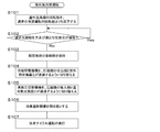
- FIG. 3 is a schematic configuration diagram showing an example of the refrigerant circuit configuration when the heat exchanger division control is performed during the low outside air cooling operation of the refrigeration cycle apparatus 100A.
- FIG. 4 is a flowchart for explaining the flow of processing during the low outside air cooling operation of the refrigeration cycle apparatus 100A. Based on FIG.3 and FIG.4, the heat exchanger division
- the refrigerant flows through both the indoor heat exchanger 5a and the indoor heat exchanger 5b, and therefore will be described together with the indoor heat exchanger 5.
- the flow of the refrigerant is indicated by broken line arrows.
- the closed control state of the refrigerant shut-off mechanism 7 is shown in black.
- the control device 50 first circulates the refrigerant in the same manner as in the normal cooling operation, thereby reducing the rotational speed of the outdoor fan 9 below the rotational speed during the normal cooling operation (step S101).
- the rotational speed of the outdoor blower 9 decreases, the air volume passing through the outdoor heat exchanger 3 also decreases. By doing so, the condensation capacity is reduced, and the condensation pressure and the compression ratio are ensured.
- the proper condensation pressure and the proper compression ratio may not be ensured.
- the control device 50 determines whether or not an appropriate condensation pressure and an appropriate compression ratio are ensured (step S102). The control device 50 determines whether or not the condensation pressure and the compression ratio are appropriate based on whether or not the condensation pressure and the compression ratio fall within a preset threshold range. If it is determined that the proper condensing pressure and the appropriate compression ratio cannot be secured (step S102; No), the control device 50 executes capacity control of the outdoor heat exchanger 3 by heat exchanger division control (step S103). .
- the control device 50 switches the cooling / heating switching mechanism 2a so that the discharge side of the compressor 1 and the outdoor heat exchanger 3 communicate with each other as shown in FIG. 1 and the outdoor heat exchanger 3 are switched so as to communicate with each other.
- the cooling / heating switching mechanism 2a is switched by the control device 50 so that the discharge side of the compressor 1 and the first refrigerant flow path 8a of the outdoor heat exchanger 3 communicate with each other as in the normal cooling operation.
- the high / low pressure switching mechanism 2b is in communication with the discharge side of the compressor 1 and the outdoor heat exchanger 3 by the cooling / heating switching mechanism 2a, and the second refrigerant flow path 8b of the suction side of the compressor 1 and the outdoor heat exchanger 3 is maintained. Is switched by the control device 50 so as to communicate with each other (step S105).
- control device 50 closes the refrigerant shut-off mechanism 7 (step S106).
- the flow path on the high pressure side of the high / low pressure switching mechanism 2b is closed as shown in FIG.
- the control device 50 circulates the refrigerant as follows, and executes the low outside air cooling operation with the heat exchanger division control (step S107).
- the outdoor heat exchanger 3 since the high / low pressure switching mechanism 2b is switched so that the suction side of the compressor 1 and the second refrigerant flow path 8b of the outdoor heat exchanger 3 communicate with each other, the outdoor heat exchanger 3 has the first refrigerant flow. The refrigerant is flowing only in the path 8a.
- the high-pressure liquid refrigerant sent out from the outdoor heat exchanger 3 is expanded by passing through the expansion mechanism 4 and becomes a low-temperature low-pressure gas-liquid two-phase refrigerant.
- the gas-liquid two-phase refrigerant flows into the indoor heat exchanger 5.
- the indoor heat exchanger 5 functions as an evaporator. From the indoor air supplied to the indoor heat exchanger 5 by the indoor blower 10, the low-temperature and low-pressure gas-liquid two-phase refrigerant absorbs heat and evaporates to become a low-pressure vapor refrigerant.
- the space to be cooled is cooled by heat exchange in the indoor heat exchanger 5.
- the low-pressure vapor refrigerant is sucked into the compressor 1 via the cooling / heating switching mechanism 2a and thereafter circulates in the refrigeration cycle in the same process.
- the refrigerant does not flow through the second refrigerant flow path 8b of the outdoor heat exchanger 3.
- the internal pressure of the second refrigerant flow path 8b becomes substantially equal to the suction pressure of the compressor 1. For this reason, if the outside air temperature is equal to or higher than the saturation temperature of the compressor suction refrigerant pressure, the condensation and retention of the refrigerant in the second refrigerant flow path 8b can be significantly suppressed.
- the condensation heat of the refrigerant flowing through the first refrigerant channel 8a passes through the fins 40 through the second refrigerant channel 8b. It is transmitted by heat conduction. Therefore, in the refrigeration cycle apparatus 100A, the temperature of the second refrigerant flow path 8b can be maintained higher than the saturation temperature of the compressor suction refrigerant pressure.
- the closing performance of the closing valve as the refrigerant shut-off mechanism 7 is poor, and the refrigerant leaks and the second refrigerant Even when flowing into the flow path 8b, the refrigerant does not condense and stay in the second refrigerant flow path 8b.
- the refrigeration cycle apparatus 100A does not perform the heating operation, the cooling / heating switching mechanism 2a is unnecessary, and the closing valve as the refrigerant shut-off mechanism 7 can be replaced with a check valve, thereby reducing the cost accordingly. It becomes.
- the heat radiation to the outside air in the second refrigerant flow path 8b is larger than the heat transfer amount from the first refrigerant flow path 8a, and the temperature of the second refrigerant flow path 8b is set to the compressor suction refrigerant pressure. May not be kept above the saturation temperature of. In this case, condensation of the refrigerant in the second refrigerant flow path 8b is inevitable.
- the liquid refrigerant condensed in the second refrigerant flow path 8b passes through the high-low pressure switching mechanism 2b according to gravity by setting the installation position of the refrigerant shut-off mechanism 7 above the high-low pressure switching mechanism 2b in a horizontal position. It is possible to easily flow out to the suction side of the compressor 1. By doing so, it may be possible to suppress the residence of the condensed refrigerant and maintain the condensation pressure and compression ratio of the refrigeration cycle appropriately.
- the refrigerant evaporation temperature inside the indoor heat exchanger 5 and the saturation temperature of the compressor suction refrigerant are the same temperature. .
- the cooling / heating switching mechanism 2a and the high / low pressure switching mechanism 2b are connected as close to the intake port of the compressor 1 as possible.
- FIG. FIG. 5 is a schematic configuration diagram showing an example of a refrigerant circuit configuration of a refrigeration cycle apparatus (hereinafter referred to as refrigeration cycle apparatus 100B) according to Embodiment 2 of the present invention.
- refrigeration cycle apparatus 100B A refrigeration cycle apparatus 100B according to Embodiment 2 of the present invention will be described based on FIG.
- differences from the first embodiment will be mainly described, and the same parts as those in the first embodiment will be denoted by the same reference numerals and description thereof will be omitted.
- the basic configuration and operation of the refrigeration cycle apparatus 100B are the same as those of the refrigeration cycle apparatus 100A according to Embodiment 1.
- the refrigeration cycle apparatus 100A according to Embodiment 1 employs a configuration in which both the first refrigerant flow path 8a and the second refrigerant flow path 8b are branched into a plurality and pass through the outdoor heat exchanger 3.
- the refrigeration cycle apparatus 100B employs a configuration in which both the first refrigerant flow path 8a and the second refrigerant flow path 8b pass through the outdoor heat exchanger 3 as a series of flow paths.
- both the first refrigerant flow path 8a and the second refrigerant flow path 8b are a series of flow paths, and the flow path length of the outdoor heat exchanger 3 is increased, so that Although there is a concern about performance degradation due to an increase in pressure loss, since the refrigerant is not multi-branched, there is an effect that there is no concern about performance degradation due to uneven distribution of the refrigerant.
- FIG. FIG. 6 is a schematic configuration diagram schematically showing an example of a schematic configuration of the outdoor heat exchanger 3 used in the refrigeration cycle apparatus according to Embodiment 3 of the present invention. Based on FIG. 6, the refrigeration cycle apparatus according to Embodiment 3 of the present invention will be described.
- the third embodiment differences from the first and second embodiments will be mainly described, and the same parts as those in the first and second embodiments will be denoted by the same reference numerals and the description thereof will be omitted.
- the basic configuration and operation of the refrigeration cycle apparatus according to Embodiment 3 are the same as those of the refrigeration cycle apparatus 100A according to Embodiment 1. However, in the refrigeration cycle apparatus according to the first and second embodiments, the configuration in which the first refrigerant flow path 8a and the second refrigerant flow path 8b are alternately arranged in the outdoor heat exchanger 3 is employed. In the refrigeration cycle apparatus according to No. 3, a configuration is adopted in which the first refrigerant flow path 8a and the second refrigerant flow path 8b share the fins 40 in the outdoor heat exchanger 3 and are arranged adjacent to each other.
- the configuration of the outdoor heat exchanger 3 is such that the first refrigerant flow path 8a and the second refrigerant flow path 8b are arranged adjacent to each other as shown in FIG. I made it. Note that it is not necessary for the entire second refrigerant flow path 8b to share the first refrigerant flow path 8a and the fin 40. More than half of the entire length of the second refrigerant flow path 8b includes the first refrigerant flow path 8a and the fin 40. It may be common.
- the outdoor heat exchanger 3 is provided with two or more rows of the first refrigerant channel 8a and the second refrigerant channel 8b, and the first refrigerant channel 8a. And since the 2nd refrigerant
- the present invention is not limited to the contents described in each embodiment, and is appropriately within the scope not departing from the gist of the present invention. Can be changed.
- a multi-type refrigeration cycle apparatus in which two indoor units and one outdoor unit are connected has been described as an example. It may be a single type refrigeration cycle device connected to one outdoor unit. Further, the refrigeration cycle may have other shutoff valves and expansion mechanisms, may have pressure vessels such as accumulators and receivers, and may have various bypass pipes and internal heat exchangers. .
Abstract
冷凍サイクル装置は、圧縮機、第1熱交換器、膨張機構、及び、第2熱交換器を配管接続した冷媒回路を有し、前記第1熱交換器は複数のフィンを共有した第1冷媒流路及び第2冷媒流路を有し、前記第1冷媒流路及び前記第2冷媒流路はそれぞれ冷媒回路上並列に配置されており、前記第1熱交換器が凝縮器として機能する運転時の冷媒の流れにおいて、前記第2冷媒流路の、前記第1熱交換器の入口側に冷媒の流れを切り替える高低圧切替機構を設け、前記第1熱交換器の出口側に冷媒の流れを遮断する冷媒遮断機構を設けたものである。
Description
本発明は、冷房運転時においても、冷凍サイクルの運転に必要な凝縮圧力及び圧縮比を確保できるようにした冷凍サイクル装置に関するものである。
空気調和装置等として使用される冷凍サイクル装置は、一般的に、圧縮機、四方弁、室外熱交換器、膨張弁、室内熱交換器を順次接続した冷媒回路を有している。このような冷凍サイクル装置においては、冷房運転時に、圧縮機から吐出された高温高圧の冷媒が、室外熱交換器を流れる間に室外空気と熱交換することで凝縮液化される。凝縮液化した冷媒は、膨張弁で減圧されてから、室内側熱交換器を流れる間に室内空気と熱交換することで蒸発ガス化される。
このような冷凍サイクル装置では、室外空気乾球温度が室内熱交換器内の冷媒蒸発温度よりも低い状態での冷房運転時(以下、低外気冷房運転時と称する)において、特別な制御を行わないと、室外熱交換器の凝縮能力が過大となり、凝縮圧力が低下してしまう。こうなると、冷凍サイクルの運転、特に圧縮機の運転に最低限必要な凝縮圧力及び圧縮比が確保できないことになってしまう。
そこで、低外気冷房運転時に、室外熱交換器の凝縮能力を低下させ、必要な凝縮圧力及び圧縮比を得るようにした技術が提案されている(例えば、特許文献1参照)。この特許文献1では、室外熱交換器の送風機回転数を低下させて熱交換器通過風量を低下させる制御、複数の室外熱交換器のうち一部を閉止することで、熱交換器容積を低下させる制御等を外気温度の低下に応じて実行し、低外気冷房運転時における必要な凝縮圧力及び圧縮比を得るようにしている。
しかしながら、特許文献1に開示された技術では、室外熱交換器の送風機回転数を低下させると室外熱交換器通過風量の外風依存度が大きくなり、外風変動時に冷凍サイクルが不安定化しやすくなる。そのため、室外熱交換器の送風機回転数の低下による熱交換器容量制御には限度があるという課題がある。
また、特許文献1に開示された技術では、閉止弁及び逆止弁による室外熱交換器の閉止制御を行っているが、閉止弁及び逆止弁の閉止能力には限度がある。そのため、閉止弁及び逆止弁から冷媒が室外熱交換器に徐々に漏れ入り、室外熱交換器に冷媒が凝縮滞留し、冷凍サイクルが冷媒不足の運転となり、凝縮圧力及び圧縮比が低下するといった課題がある。
本発明は、上記のような課題を解決するためになされたもので、低外気冷房運転時においても、冷凍サイクルの運転に必要な凝縮圧力及び圧縮比を確保する熱交換器容量制御を有する冷凍サイクル装置を提供するものである。
本発明に係る冷凍サイクル装置は、圧縮機、第1熱交換器、膨張機構、及び、第2熱交換器を配管接続した冷媒回路を有し、前記第1熱交換器は複数のフィンを共有した第1冷媒流路及び第2冷媒流路を有し、前記第1冷媒流路及び前記第2冷媒流路はそれぞれ冷媒回路上並列に配置されており、前記第1熱交換器が凝縮器として機能する運転時の冷媒の流れにおいて、前記第2冷媒流路の、前記第1熱交換器の入口側に冷媒の流れを切り替える高低圧切替機構を設け、前記第1熱交換器の出口側に冷媒の流れを遮断する冷媒遮断機構を設けたものである。
本発明に係る冷凍サイクル装置は、第1熱交換器が凝縮器として機能する運転時の冷媒の流れにおいて、第2冷媒流路の、第1熱交換器の入口側に高低圧切替機構を設け、第1熱交換器の出口側に冷媒遮断機構を設けたので、第2冷媒流路への冷媒の流れを遮断する熱交換器容量制御が実行できる。そのため、本発明に係る冷凍サイクル装置によれば、第1熱交換器で熱交換する空気の乾球温度が、第2熱交換器内の冷媒蒸発温度よりも低い冷房運転時においても、第1熱交換器内での液冷媒の凝縮滞留を大幅に抑制でき、冷凍サイクルの運転に必要な凝縮圧力及び圧縮比を確保することができる。
以下、本発明に係る冷凍サイクル装置について、図面を用いて説明する。
なお、以下で説明する構成、動作等は、一例にすぎず、本発明に係る冷凍サイクル装置は、そのような構成、動作等である場合に限定されない。また、各図において、同一又は類似するものには、同一の符号を付すか、又は、符号を付すことを省略している。また、細かい構造については、適宜図示を簡略化又は省略している。また、重複又は類似する説明については、適宜簡略化又は省略している。
なお、以下で説明する構成、動作等は、一例にすぎず、本発明に係る冷凍サイクル装置は、そのような構成、動作等である場合に限定されない。また、各図において、同一又は類似するものには、同一の符号を付すか、又は、符号を付すことを省略している。また、細かい構造については、適宜図示を簡略化又は省略している。また、重複又は類似する説明については、適宜簡略化又は省略している。
実施の形態1.
図1は、本発明の実施の形態1に係る冷凍サイクル装置(以下、冷凍サイクル装置100Aと称する)の冷媒回路構成の一例を示す概略構成図である。なお、図1では、冷媒の流れを破線矢印で示している。また、図1では、冷媒遮断機構7の開制御状態を白塗りで表している。温度、圧力等の高低については、特に絶対的な値との関係で高低等が定まっているものではなく、システム、装置等における状態、動作等において相対的に定まるものとする。
図1は、本発明の実施の形態1に係る冷凍サイクル装置(以下、冷凍サイクル装置100Aと称する)の冷媒回路構成の一例を示す概略構成図である。なお、図1では、冷媒の流れを破線矢印で示している。また、図1では、冷媒遮断機構7の開制御状態を白塗りで表している。温度、圧力等の高低については、特に絶対的な値との関係で高低等が定まっているものではなく、システム、装置等における状態、動作等において相対的に定まるものとする。
<冷凍サイクル装置100Aの構成>
冷凍サイクル装置100Aは、例えば、冷凍装置、冷蔵装置、空気調和装置など、冷媒回路を備えた装置に適用される。
図1に示すように、冷凍サイクル装置100Aは、圧縮機1、冷暖切替機構2a、高低圧切替機構2b、室外熱交換器(第1熱交換器)3、膨張機構4、室内熱交換器(第2熱交換器)5、および、冷媒遮断機構7を備えている。圧縮機1、冷暖切替機構2a、高低圧切替機構2b、室外熱交換器3、膨張機構4、および、室内熱交換器5が、冷媒配管8で配管接続されて、冷媒回路が形成されている。
冷凍サイクル装置100Aは、例えば、冷凍装置、冷蔵装置、空気調和装置など、冷媒回路を備えた装置に適用される。
図1に示すように、冷凍サイクル装置100Aは、圧縮機1、冷暖切替機構2a、高低圧切替機構2b、室外熱交換器(第1熱交換器)3、膨張機構4、室内熱交換器(第2熱交換器)5、および、冷媒遮断機構7を備えている。圧縮機1、冷暖切替機構2a、高低圧切替機構2b、室外熱交換器3、膨張機構4、および、室内熱交換器5が、冷媒配管8で配管接続されて、冷媒回路が形成されている。
なお、図1では、2台の室内熱交換器5が並列に設けられた場合を例に示しており、一方を室内熱交換器5a、他方を室内熱交換器5bとして図示している。また、図1では、並列に設けられた室内熱交換器5のそれぞれに膨張機構4が接続された場合を例に示しており、室内熱交換器5aに接続された方を膨張機構4a、室内熱交換器5bに接続された方を膨張機構4bとして図示している。ただし、室内熱交換器5aと室内熱交換器5b、膨張機構4aと膨張機構4bを特に区別する必要がない場合は、室内熱交換器5、膨張機構4として説明する。
圧縮機1は、冷媒を圧縮するものである。圧縮機1で圧縮された冷媒は、吐出されて冷暖切替機構2a、高低圧切替機構2bへ送られる。圧縮機1は、例えば、ロータリ圧縮機、スクロール圧縮機、スクリュー圧縮機、往復圧縮機等で構成することができる。
冷暖切替機構2aは、圧縮機1の吐出側に設けられ、暖房運転と冷房運転とにおいて冷媒の流れを切り替えるものである。つまり、冷暖切替機構2aは、暖房運転時には圧縮機1と室内熱交換器5とを接続するように切り替えられ、冷房運転時には圧縮機と室外熱交換器3とを接続するように切り替えられる。なお、冷暖切替機構2aの構成を特に限定するものではないが、例えば図1に示すように四方弁で冷暖切替機構2aを構成するとよい。
高低圧切替機構2bは、圧縮機1と冷暖切替機構2aとの間と室外熱交換器3とを接続している冷媒配管8に設けられ、運転状態によって冷媒の流れを切り替えるものである。つまり、高低圧切替機構2bは、運転状態によって圧縮機1の吐出側と室外熱交換器3の第2冷媒流路8bとを接続するように切り替えられ、運転状態によって圧縮機1の吸入側と室外熱交換器3の第2冷媒流路8bと接続するように切り替えられる。なお、高低圧切替機構2bの構成を特に限定するものではないが、例えば図1に示すように四方弁で高低圧切替機構2bを構成するとよい。
室外熱交換器3は、暖房運転時には蒸発器として機能し、冷房運転時には凝縮器として機能するものである。室外熱交換器3は、それぞれ冷媒回路上並列構成となる第1冷媒流路8a及び第2冷媒流路8bを有している。第1冷媒流路8a及び第2冷媒流路8bは、例えばフィン40を共有するフィン・アンド・チューブ型熱交換器の伝熱管として製造される。また、室外熱交換器3は、例えば図1に示すように第1冷媒流路8a及び第2冷媒流路8bを構成するそれぞれの伝熱管を交互に配置するように構成されている。そして、室外熱交換器3は、第1冷媒流路8a及び第2冷媒流路8bにより、分割利用が可能に構成されている。
室外熱交換器3の分割利用とは、第1冷媒流路8a及び第2冷媒流路8bを利用して冷媒を流すことにより、熱交換に寄与する領域を部分的に利用することである。なお、以下の説明において、冷凍サイクル装置100Aにおいて室外熱交換器3を分割利用している運転時を、冷凍サイクル装置100Aの熱交換器分割制御時と称するものとする。
膨張機構4は、室内熱交換器5又は室外熱交換器3を経由した冷媒を膨張させて減圧するものである。膨張機構4は、例えば冷媒の流量を調整可能な電動膨張弁等で構成するとよい。なお、膨張機構4としては、電動膨張弁だけでなく、受圧部にダイアフラムを採用した機械式膨張弁、または、キャピラリーチューブ等を適用することも可能である。
室内熱交換器5は、暖房運転時には凝縮器として機能し、冷房運転時には蒸発器として機能するものである。室内熱交換器5は、例えば、フィン・アンド・チューブ型熱交換器、マイクロチャネル熱交換器、シェルアンドチューブ式熱交換器、ヒートパイプ式熱交換器、二重管式熱交換器、プレート熱交換器等で構成することができる。なお、ここでは、室内熱交換器5がフィン・アンド・チューブ型熱交換器である場合を例に説明する。
冷媒遮断機構7は、第2冷媒流路8bに設けられ、第2冷媒流路8bを開閉するものである。冷媒遮断機構7は、例えば、閉止弁や二方弁で構成するとよい。ここでは、冷媒遮断機構7が閉止弁である場合を例に示している。
冷媒配管8は、冷凍サイクル装置100Aの各要素機器を接続するものである。冷媒配管8は、室外熱交換器3においては第1冷媒流路8aと第2冷媒流路8bとに分割される。
第1冷媒流路8aは、冷媒配管8の一部と伝熱管で構成され、熱交換器分割制御時においても冷媒が流通する。
第2冷媒流路8bは、冷媒配管8の一部と伝熱管で構成され、熱交換器分割制御時には冷媒が流通しない。
第1冷媒流路8aは、冷媒配管8の一部と伝熱管で構成され、熱交換器分割制御時においても冷媒が流通する。
第2冷媒流路8bは、冷媒配管8の一部と伝熱管で構成され、熱交換器分割制御時には冷媒が流通しない。
また、冷凍サイクル装置100Aは、室外送風機9及び室内送風機10を有している。 室外送風機9は、室外熱交換器3に付設されており、室外熱交換器3に熱交換流体である空気を供給するものである。
室内送風機10は、室内熱交換器5に付設されており、室内熱交換器5に熱交換流体である空気を供給するものである。
室内送風機10は、室内熱交換器5に付設されており、室内熱交換器5に熱交換流体である空気を供給するものである。
なお、図1では、並列に設けられた室内熱交換器5のそれぞれに室内送風機10が設けられた場合を例に示しており、室内熱交換器5aに設けられた方を室内送風機10a、室内熱交換器5bに設けられた方を室内送風機10bとして図示している。ただし、室内送風機10aと室内送風機10bを特に区別する必要がない場合は、室内送風機10として説明する。
さらに、冷凍サイクル装置100Aは、冷凍サイクル装置100Aを統括制御する制御装置50を有している。制御装置50には、例えば、圧縮機1、冷暖切替機構2a、高低圧切替機構2b、膨張機構4、冷媒遮断機構7、室外送風機9、室内送風機10、図示省略の各種センサ等が電気的に接続される。
制御装置50は、各種センサからの検出値に基づき、各アクチュエータ(圧縮機1、冷暖切替機構2a、高低圧切替機構2b、膨張機構4、冷媒遮断機構7、室外送風機9、室内送風機10などの駆動部品)の制御を行う。制御装置50は、その機能を実現する回路デバイスのようなハードウェアで構成することもできるし、マイコンまたはCPUのような演算装置と、その上で実行されるソフトウェアとにより構成することもできる。
<冷凍サイクル装置100Aの動作>
次に、冷凍サイクル装置100Aの動作について、冷媒の流れとともに説明する。まず、図1に基づいて、冷凍サイクル装置100Aが実行する通常の冷房運転について説明する。なお、図1は、冷凍サイクル装置100Aの通常の冷房運転時の冷媒回路構成を示している。また、通常の冷房運転では、室内熱交換器5a、室内熱交換器5bのいずれにも冷媒が流れるようになっているため、室内熱交換器5とまとめて説明するものとする。膨張機構4、室内送風機10についても同様である。
次に、冷凍サイクル装置100Aの動作について、冷媒の流れとともに説明する。まず、図1に基づいて、冷凍サイクル装置100Aが実行する通常の冷房運転について説明する。なお、図1は、冷凍サイクル装置100Aの通常の冷房運転時の冷媒回路構成を示している。また、通常の冷房運転では、室内熱交換器5a、室内熱交換器5bのいずれにも冷媒が流れるようになっているため、室内熱交換器5とまとめて説明するものとする。膨張機構4、室内送風機10についても同様である。
通常の冷房運転時は、制御装置50は、図1に示すように冷暖切替機構2a及び高低圧切替機構2bを圧縮機1の吐出側と室外熱交換器3とが連通するように切り替える。具体的には、冷暖切替機構2aは、圧縮機1の吐出側と室外熱交換器3の第1冷媒流路8aとが連通するように制御装置50により切り替えられる。高低圧切替機構2bは、圧縮機1の吐出側と室外熱交換器3の第2冷媒流路8bとが連通するように制御装置50により切り替えられる。また、冷媒遮断機構7は制御装置50により開状態に制御されている。なお、高低圧切替機構2bの低圧側の流路は、図1に示すように閉塞されている。
圧縮機1の駆動により、圧縮機1から高温高圧の蒸気冷媒が吐出する。圧縮機1で高温高圧にされた蒸気冷媒は、圧縮機1の吐出側で分岐し、冷暖切替機構2a若しく高低圧切替機構2bを通過し、室外熱交換器3に流入する。通常の冷房運転時において、室外熱交換器3は、凝縮器として機能する。室外送風機9により室外熱交換器3に供給された室外空気に対して、高温高圧の蒸気冷媒は、放熱を行い、凝縮し、高圧の液冷媒となる。
室外熱交換器3から送り出された高圧の液冷媒は、膨張機構4を通過することで、膨張し、低温低圧の気液二相冷媒となる。気液二相冷媒は、室内熱交換器5に流入する。通常の冷房運転時において、室内熱交換器5は、蒸発器として機能する。室内送風機10により室内熱交換器5に供給された室内空気から、低温低圧の気液二相冷媒は、吸熱を行い、蒸発し、低圧の蒸気冷媒となる。室内熱交換器5での熱交換によって、冷房対象空間が冷却されることになる。
その後、低圧の蒸気冷媒は、冷暖切替機構2aを経由し、圧縮機1に吸入され、以降同様の過程で冷凍サイクルを循環する。
次に、図2に基づいて、冷凍サイクル装置100Aが実行する暖房運転について説明する。なお、図2は、冷凍サイクル装置100Aの暖房運転時の冷媒回路構成の一例を示す概略構成図である。また、暖房運転では、室内熱交換器5a、室内熱交換器5bのいずれにも冷媒が流れるようになっているため、室内熱交換器5とまとめて説明するものとする。膨張機構4、室内送風機10についても同様である。さらに、図2では、冷媒の流れを破線矢印で示している。図2では、冷媒遮断機構7の開制御状態を白塗りで表している。
暖房運転時は、制御装置50は、図2に示すように冷暖切替機構2a及び高低圧切替機構2bを圧縮機1の吸入側と室外熱交換器3とが連通するように切り替える。具体的には、冷暖切替機構2aは、圧縮機1の吸入側と室外熱交換器3の第1冷媒流路8aとが連通するように制御装置50により切り替えられる。高低圧切替機構2bは、圧縮機1の吸入側と室外熱交換器3の第2冷媒流路8bとが連通するように制御装置50により切り替えられる。また、冷媒遮断機構7は制御装置50により開状態に制御されている。なお、高低圧切替機構2bの高圧側の流路は、図2に示すように閉塞されている。
圧縮機1の駆動により、圧縮機1から高温高圧の蒸気冷媒が吐出する。圧縮機1で高温高圧にされた蒸気冷媒は、冷暖切替機構2aを通過し、室内熱交換器5に流入する。暖房運転時において、室内熱交換器5は、凝縮器として機能する。室内送風機10により室内熱交換器5に供給された室内空気に対して、高温高圧の蒸気冷媒は、放熱を行い、凝縮し、高圧の液冷媒となる。室内熱交換器5での熱交換によって、暖房対象空間が暖房されることになる。
室内熱交換器5から送り出された高圧の液冷媒は、膨張機構4を通過することで、膨張し、低温低圧の気液二相冷媒となる。気液二相冷媒は、室外熱交換器3に流入する。暖房運転時において、室外熱交換器3は、蒸発器として機能する。室外送風機9により室外熱交換器3に供給された室外空気から、低温低圧の気液二相冷媒は、吸熱を行い、蒸発し、低圧の蒸気冷媒となる。
その後、低圧の蒸気冷媒は、冷暖切替機構2a若しく高低圧切替機構2bを経由し、圧縮機1に吸入され、以降同様の過程で冷凍サイクルを循環する。
次に、冷凍サイクル装置100Aの低外気冷房運転について説明する。低外気冷房運転とは、室外空気乾球温度が室内熱交換器5内の冷媒蒸発温度よりも低い状態での冷房運転を意味している。低外気冷房運転時は、通常の冷房運転時と比較し、室外熱交換器3内の冷媒凝縮温度と室外空気温度との差が広がりやすく、室外熱交換器3の凝縮能力が過大となりやすい。そのため、冷凍サイクルの運転、特に圧縮機1の運転に必要な、凝縮圧力及び圧縮比が確保しにくくなる。
そこで、冷凍サイクル装置100Aでは、まず図1に示す冷媒回路構成にて、室外送風機9の回転数を低下させ、室外熱交換器3を通過する風量を低下させる。こうすることで、冷凍サイクル装置100Aでは、凝縮能力を低下させることができ、凝縮圧力及び圧縮比を確保する。
ただし、室外送風機9の回転数を低下させると室外熱交換器3の通過風量の外風依存度が大きくなり、外風変動時に冷凍サイクルが不安定化しやすくなる。つまり、室外送風機9の回転数低下による熱交換器容量制御には限度がある。なお、外風影響も加味した室外送風機9の回転数低下許容値は、最大回転数の10パーセント前後である。
室外送風機9の回転数を制御許容上の最低値まで低下させても、適正凝縮圧力及び適正圧縮比が確保できない場合、冷凍サイクル装置100Aでは、熱交換器分割制御により室外熱交換器3の容量制御を実行するようになっている。
図3は、冷凍サイクル装置100Aの低外気冷房運転時における熱交換器分割制御を実行している際の冷媒回路構成の一例を示す概略構成図である。図4は、冷凍サイクル装置100Aの低外気冷房運転時の処理の流れを説明するフローチャートである。図3及び図4に基づいて、冷凍サイクル装置100Aの低外気冷房運転時における熱交換器分割制御について説明する。
なお、低外気冷房運転では、室内熱交換器5a、室内熱交換器5bのいずれにも冷媒が流れるようになっているため、室内熱交換器5とまとめて説明するものとする。膨張機構4、室内送風機10についても同様である。さらに、図3では、冷媒の流れを破線矢印で示している。図3では、冷媒遮断機構7の閉制御状態を黒塗りで表している。
低外気冷房運転時では、制御装置50は、まず通常の冷房運転と同様に冷媒を循環させて、室外送風機9の回転数を通常の冷房運転時の回転数よりも低下させる(ステップS101)。室外送風機9の回転数が低下すると、室外熱交換器3を通過する風量も低下する。こうすることで、凝縮能力を低下させ、凝縮圧力及び圧縮比を確保する。しかしながら、上述したように、室外送風機9の回転数を制御許容上の最低値まで低下させても、適正凝縮圧力及び適正圧縮比が確保できない場合がある。
そこで、制御装置50は、適正凝縮圧力及び適正圧縮比が確保できているかどうかを判断する(ステップS102)。制御装置50は、凝縮圧力及び圧縮比が予め設定されている閾値の範囲になるかどうかで凝縮圧力及び圧縮比が適正であるかどうかを判断する。そして、適正凝縮圧力及び適正圧縮比が確保できていないと判断すると(ステップS102;No)、制御装置50は、熱交換器分割制御により室外熱交換器3の容量制御を実行する(ステップS103)。
低外気冷房運転は、制御装置50は、図3に示すように冷暖切替機構2aを圧縮機1の吐出側と室外熱交換器3とが連通するように切り替え、高低圧切替機構2bを圧縮機1の吸入側と室外熱交換器3とが連通するように切り替える。具体的には、冷暖切替機構2aは、通常の冷房運転時と同様に、圧縮機1の吐出側と室外熱交換器3の第1冷媒流路8aとが連通するように制御装置50により切り替えられる(ステップS104)。高低圧切替機構2bは、冷暖切替機構2aによる圧縮機1の吐出側と室外熱交換器3との連通状態のまま、圧縮機1の吸入側と室外熱交換器3の第2冷媒流路8bとが連通するように制御装置50により切り替えられる(ステップS105)。
また、制御装置50は、冷媒遮断機構7を閉状態にする(ステップS106)。なお、高低圧切替機構2bの高圧側の流路は、図3に示すように閉塞されている。このような状態にして、制御装置50は、以下のように冷媒を循環させて、熱交換器分割制御を伴った低外気冷房運転を実行する(ステップS107)。
圧縮機1の駆動により、圧縮機1から高温高圧の蒸気冷媒が吐出する。圧縮機1で高温高圧にされた蒸気冷媒は、冷暖切替機構2aを通過し、室外熱交換器3に流入する。低外気冷房運転時において、室外熱交換器3は、凝縮器として機能する。室外送風機9により室外熱交換器3に供給された室外空気に対して、高温高圧の蒸気冷媒は放熱を行い、凝縮し、高圧の液冷媒となる。ただし、高低圧切替機構2bが圧縮機1の吸入側と室外熱交換器3の第2冷媒流路8bとが連通するように切り替えられているため、室外熱交換器3では、第1冷媒流路8aにしか冷媒が流れていない。
室外熱交換器3から送り出された高圧の液冷媒は、膨張機構4を通過することで、膨張し、低温低圧の気液二相冷媒となる。気液二相冷媒は、室内熱交換器5に流入する。低外気冷房運転時において、室内熱交換器5は、蒸発器として機能する。室内送風機10により室内熱交換器5に供給された室内空気から、低温低圧の気液二相冷媒は、吸熱を行い、蒸発し、低圧の蒸気冷媒となる。室内熱交換器5での熱交換によって、冷房対象空間が冷却されることになる。
その後、低圧の蒸気冷媒は、冷暖切替機構2aを経由し、圧縮機1に吸入され、以降同様の過程で冷凍サイクルを循環する。
このように高低圧切替機構2bを切り替えることで、冷凍サイクル装置100Aでは、室外熱交換器3の第2冷媒流路8bには冷媒が流通しなくなる。それとともに、第2冷媒流路8bの内部圧力が圧縮機1の吸入圧力とほぼ同等となる。このため、外気温度が圧縮機吸入冷媒圧力の飽和温度以上であれば、第2冷媒流路8b内の冷媒の凝縮滞留を大幅に抑制できる。
また、冷凍サイクル装置100Aでは、外気温度が圧縮機吸入冷媒圧力の飽和温度未満の場合でも、第2冷媒流路8bには、第1冷媒流路8aを流れる冷媒の凝縮熱がフィン40を通じた熱伝導により伝わることになる。そのため、冷凍サイクル装置100Aにおいては、第2冷媒流路8bの温度を圧縮機吸入冷媒圧力の飽和温度よりも高く維持することが可能になる。
第2冷媒流路8bの温度が、圧縮機吸入冷媒圧力の飽和温度よりも高く維持することが可能なため、冷媒遮断機構7としての閉止弁の閉止性能が悪く、冷媒が漏れて第2冷媒流路8b内に流入する場合でも、第2冷媒流路8b内にて、冷媒が凝縮滞留することはない。
なお、冷凍サイクル装置100Aが暖房運転を実施しない場合は、冷暖切替機構2aは不要であり、また冷媒遮断機構7としての閉止弁を逆止弁に置き換えることができ、その分のコスト減が可能となる。
なお、冷凍サイクル装置100Aが暖房運転を実施しない場合は、冷暖切替機構2aは不要であり、また冷媒遮断機構7としての閉止弁を逆止弁に置き換えることができ、その分のコスト減が可能となる。
以上の操作と、室外熱交換器3の構成により、外気温度が圧縮機吸入冷媒圧力の飽和温度未満の場合でも、第2冷媒流路8b内での冷媒の凝縮滞留を大幅に抑制でき、冷凍サイクルの凝縮圧力及び圧縮比を確保できる。
外気温度が更に低い場合は、第2冷媒流路8bの外気への放熱が、第1冷媒流路8aからの伝熱量よりも多くなり、第2冷媒流路8bの温度を圧縮機吸入冷媒圧力の飽和温度以上に保てない場合がある。この場合、第2冷媒流路8b内での冷媒の凝縮は避けられない。一方で、冷媒遮断機構7の設置位置を高低圧切替機構2bよりも水平位置にて上方にすることにより、第2冷媒流路8b内に凝縮した液冷媒が重力に従って高低圧切替機構2bを通り、圧縮機1の吸入側に流出しやすくできる。こうすることで、凝縮冷媒の滞留を抑制し、冷凍サイクルの凝縮圧力及び圧縮比を適正に維持することが可能な場合がある。
なお、冷房運転時に、図示省略の室内機及び室外機の接続配管の圧力損失を考慮しない場合、室内熱交換器5の内部の冷媒蒸発温度と、圧縮機吸入冷媒の飽和温度は同一温度である。
また、暖房運転時の冷媒配管内圧力損失を小さくするために、冷暖切替機構2a及び高低圧切替機構2bは、なるべく圧縮機1の吸入口に近接して接続することが好ましい。
実施の形態2.
図5は、本発明の実施の形態2に係る冷凍サイクル装置(以下、冷凍サイクル装置100Bと称する)の冷媒回路構成の一例を示す概略構成図である。図5に基づいて、本発明の実施の形態2に係る冷凍サイクル装置100Bについて説明する。なお、実施の形態2では実施の形態1との相違点を中心に説明し、実施の形態1と同一部分には、同一符号を付して説明を省略するものとする。
図5は、本発明の実施の形態2に係る冷凍サイクル装置(以下、冷凍サイクル装置100Bと称する)の冷媒回路構成の一例を示す概略構成図である。図5に基づいて、本発明の実施の形態2に係る冷凍サイクル装置100Bについて説明する。なお、実施の形態2では実施の形態1との相違点を中心に説明し、実施の形態1と同一部分には、同一符号を付して説明を省略するものとする。
冷凍サイクル装置100Bの基本的な構成及び動作は、実施の形態1に係る冷凍サイクル装置100Aと同様である。ただし、実施の形態1に係る冷凍サイクル装置100Aでは第1冷媒流路8a及び第2冷媒流路8bのいずれもが複数に分岐されて室外熱交換器3を通過する構成を採用していたが、冷凍サイクル装置100Bでは第1冷媒流路8a及び第2冷媒流路8bのいずれもが一連の流路として室外熱交換器3を通過する構成を採用している。
冷凍サイクル装置100Bによれば、第1冷媒流路8a及び第2冷媒流路8bのいずれも一連の流路とすることで、室外熱交換器3の流路長が長くなることで流路の圧力損失増大による性能低下が懸念されるが、冷媒を多分岐としていないので冷媒の不均一分配による性能低下の心配がないという効果を得られる。
実施の形態3.
図6は、本発明の実施の形態3に係る冷凍サイクル装置に使用される室外熱交換器3の概略構成の一例を模式的に示す概略構成図である。図6に基づいて、本発明の実施の形態3に係る冷凍サイクル装置について説明する。なお、実施の形態3では実施の形態1、2との相違点を中心に説明し、実施の形態1、2と同一部分には、同一符号を付して説明を省略するものとする。
図6は、本発明の実施の形態3に係る冷凍サイクル装置に使用される室外熱交換器3の概略構成の一例を模式的に示す概略構成図である。図6に基づいて、本発明の実施の形態3に係る冷凍サイクル装置について説明する。なお、実施の形態3では実施の形態1、2との相違点を中心に説明し、実施の形態1、2と同一部分には、同一符号を付して説明を省略するものとする。
実施の形態3に係る冷凍サイクル装置の基本的な構成及び動作は、実施の形態1に係る冷凍サイクル装置100Aと同様である。ただし、実施の形態1、2に係る冷凍サイクル装置では室外熱交換器3において第1冷媒流路8a及び第2冷媒流路8bを交互に並べられた構成を採用していたが、実施の形態3に係る冷凍サイクル装置では室外熱交換器3において第1冷媒流路8a及び第2冷媒流路8bがフィン40を共通とし、列毎に隣接配置された構成を採用している。
すなわち、室外熱交換器3が2列以上の流路構成を備えていれば、第1冷媒流路8a及び第2冷媒流路8bのフィン40を共通とし、それらを列毎に隣接して配置させることも可能である。そこで、実施の形態3に係る冷凍サイクル装置では、室外熱交換器3の構成を図6に示すように第1冷媒流路8a及び第2冷媒流路8bを列毎に隣接して配置させるようにした。なお、第2冷媒流路8bの全部が第1冷媒流路8aとフィン40を共通としている必要はなく、第2冷媒流路8bの全長の半分以上が第1冷媒流路8aとフィン40を共通としていればよい。
実施の形態3に係る冷凍サイクル装置によれば、室外熱交換器3として第1冷媒流路8a及び第2冷媒流路8bがそれぞれ2列以上備えたものを使用し、第1冷媒流路8a及び第2冷媒流路8bが列毎に隣接配置され、それらがフィン40を共通としているので、実施の形態1、2に係る冷凍サイクル装置と同様の効果を得られる。
本発明の実施の形態を実施の形態1~3に分けて説明したが、本発明は各実施の形態で説明した内容に限定されるものではなく、本発明の要旨を逸脱しない範囲内において適宜変更することができる。例えば、実施の形態では、2台の室内機と1台の室外機とを接続したマルチ型の冷凍サイクル装置を例に説明したが、必ずしもマルチ型である必要はなく、1台の室内機と1台の室外機とを接続したシングル型の冷凍サイクル装置であってもよい。また、冷凍サイクル内に、他の締切弁や膨張機構を有していたり、アキュムレーターやレシーバーのような圧力容器を有していたり、各種バイパス配管や内部熱交換器を有していてもよい。
1 圧縮機、2a 冷暖切替機構、2b 高低圧切替機構、3 室外熱交換器、4 膨張機構、4a 膨張機構、4b 膨張機構、5 室内熱交換器、5a 室内熱交換器、5b 室内熱交換器、7 冷媒遮断機構、8 冷媒配管、8a 第1冷媒流路、8b 第2冷媒流路、9 室外送風機、10 室内送風機、10a 室内送風機、10b 室内送風機、40 フィン、50 制御装置、100A 冷凍サイクル装置、100B 冷凍サイクル装置。
Claims (9)
- 圧縮機、第1熱交換器、膨張機構、及び、第2熱交換器を配管接続した冷媒回路を有し、
前記第1熱交換器は複数のフィンを共有した第1冷媒流路及び第2冷媒流路を有し、
前記第1冷媒流路及び前記第2冷媒流路はそれぞれ冷媒回路上並列に配置されており、
前記第1熱交換器が凝縮器として機能する運転時の冷媒の流れにおいて、
前記第2冷媒流路の、前記第1熱交換器の入口側に冷媒の流れを切り替える高低圧切替機構を設け、前記第1熱交換器の出口側に冷媒の流れを遮断する冷媒遮断機構を設けた
冷凍サイクル装置。 - 前記第1熱交換器が凝縮器として機能する運転時において、
前記冷媒遮断機構を開け、前記第2冷媒流路を、前記高低圧切替機構を介して高圧側に接続して前記第2冷媒流路に冷媒を流通させる
請求項1に記載の冷凍サイクル装置。 - 前記第1熱交換器が凝縮器として機能する運転時であって、前記第1熱交換器で熱交換する空気の乾球温度が前記第2熱交換器の冷媒蒸発温度よりも低いとき、
前記冷媒遮断機構を閉じ、前記第2冷媒流路を、前記高低圧切替機構を介して高圧側から低圧側に切り替えて接続して前記第2冷媒流路への冷媒の流通を遮断する
請求項2に記載の冷凍サイクル装置。 - 前記第1冷媒流路及び前記第2冷媒流路のいずれもが前記第1熱交換器において分岐されている
請求項1~3のいずれか一項に記載の冷凍サイクル装置。 - 前記第1冷媒流路及び前記第2冷媒流路のいずれもが前記第1熱交換器において一連とされている
請求項1~3のいずれか一項に記載の冷凍サイクル装置。 - 前記第1熱交換器は前記第1冷媒流路及び前記第2冷媒流路をそれぞれ2列以上備えており、
前記第1冷媒流路及び前記第2冷媒流路が列毎に隣接配置されている
請求項1~5のいずれか一項に記載の冷凍サイクル装置。 - 前記第2冷媒流路への冷媒の流通を遮断しているとき、
前記第1熱交換器に空気を供給する室外送風機の回転数が、前記第2冷媒流路に冷媒を流通しているときと比較して、低回転数である
請求項1~6のいずれか一項に記載の冷凍サイクル装置。 - 前記第2冷媒流路において、前記冷媒遮断機構の設置位置を前記高低圧切替機構よりも水平位置が高い位置とした
請求項1~7のいずれか一項に記載の冷凍サイクル装置。 - 前記冷媒遮断機構は、
閉止弁又は逆止弁で構成されている
請求項1~8のいずれか一項に記載の冷凍サイクル装置。
Priority Applications (4)
| Application Number | Priority Date | Filing Date | Title |
|---|---|---|---|
| EP16910557.4A EP3492839B1 (en) | 2016-07-29 | 2016-07-29 | Refrigeration cycle device |
| PCT/JP2016/072298 WO2018020654A1 (ja) | 2016-07-29 | 2016-07-29 | 冷凍サイクル装置 |
| US16/097,898 US10816242B2 (en) | 2016-07-29 | 2016-07-29 | Refrigeration cycle apparatus |
| JP2018530296A JP6647406B2 (ja) | 2016-07-29 | 2016-07-29 | 冷凍サイクル装置 |
Applications Claiming Priority (1)
| Application Number | Priority Date | Filing Date | Title |
|---|---|---|---|
| PCT/JP2016/072298 WO2018020654A1 (ja) | 2016-07-29 | 2016-07-29 | 冷凍サイクル装置 |
Publications (1)
| Publication Number | Publication Date |
|---|---|
| WO2018020654A1 true WO2018020654A1 (ja) | 2018-02-01 |
Family
ID=61017547
Family Applications (1)
| Application Number | Title | Priority Date | Filing Date |
|---|---|---|---|
| PCT/JP2016/072298 WO2018020654A1 (ja) | 2016-07-29 | 2016-07-29 | 冷凍サイクル装置 |
Country Status (4)
| Country | Link |
|---|---|
| US (1) | US10816242B2 (ja) |
| EP (1) | EP3492839B1 (ja) |
| JP (1) | JP6647406B2 (ja) |
| WO (1) | WO2018020654A1 (ja) |
Cited By (5)
| Publication number | Priority date | Publication date | Assignee | Title |
|---|---|---|---|---|
| CN112146302A (zh) * | 2020-09-22 | 2020-12-29 | 浙江国祥股份有限公司 | 一种蒸发冷热泵机组 |
| CN113063241A (zh) * | 2019-12-30 | 2021-07-02 | 浙江三花智能控制股份有限公司 | 换热组件 |
| US11067319B2 (en) * | 2018-03-05 | 2021-07-20 | Johnson Controls Technology Company | Heat exchanger with multiple conduits and valve control system |
| CN113757792A (zh) * | 2021-09-28 | 2021-12-07 | 美的集团股份有限公司 | 空调器 |
| WO2022059075A1 (ja) * | 2020-09-15 | 2022-03-24 | 東芝キヤリア株式会社 | 空気調和装置 |
Families Citing this family (2)
| Publication number | Priority date | Publication date | Assignee | Title |
|---|---|---|---|---|
| WO2018047330A1 (ja) * | 2016-09-12 | 2018-03-15 | 三菱電機株式会社 | 空気調和装置 |
| CN111380256A (zh) * | 2018-12-28 | 2020-07-07 | 三花控股集团有限公司 | 热泵系统 |
Citations (15)
| Publication number | Priority date | Publication date | Assignee | Title |
|---|---|---|---|---|
| JPS4978954A (ja) * | 1972-12-06 | 1974-07-30 | ||
| JPS60148573U (ja) * | 1984-03-13 | 1985-10-02 | 三菱重工業株式会社 | 空気調和装置 |
| JPH01131851A (ja) * | 1987-11-13 | 1989-05-24 | Toshiba Corp | 空気調和装置 |
| JPH02208452A (ja) * | 1989-02-07 | 1990-08-20 | Daikin Ind Ltd | 冷凍装置の均圧制御装置 |
| JPH05172429A (ja) * | 1991-06-25 | 1993-07-09 | Hitachi Ltd | 空気調和機 |
| JPH1038391A (ja) * | 1996-07-23 | 1998-02-13 | Daikin Ind Ltd | 冷凍装置 |
| JP2000274857A (ja) * | 1999-03-19 | 2000-10-06 | Fujitsu General Ltd | 空気調和機 |
| JP2004170023A (ja) * | 2002-11-21 | 2004-06-17 | Fujitsu General Ltd | 多室形空気調和機の制御方法 |
| JP2005049051A (ja) * | 2003-07-30 | 2005-02-24 | Mitsubishi Electric Corp | 空気調和装置 |
| JP2013024485A (ja) * | 2011-07-22 | 2013-02-04 | Fujitsu General Ltd | 空気調和装置 |
| JP2013029242A (ja) * | 2011-07-28 | 2013-02-07 | Fujitsu General Ltd | 空気調和装置 |
| JP2013076532A (ja) * | 2011-09-30 | 2013-04-25 | Daikin Industries Ltd | 冷凍装置 |
| JP2013122354A (ja) * | 2011-12-12 | 2013-06-20 | Samsung Electronics Co Ltd | 空気調和装置 |
| WO2014083867A1 (ja) * | 2012-11-29 | 2014-06-05 | 三菱電機株式会社 | 空気調和装置 |
| JP2016020784A (ja) * | 2014-07-15 | 2016-02-04 | 株式会社富士通ゼネラル | 空気調和装置 |
Family Cites Families (9)
| Publication number | Priority date | Publication date | Assignee | Title |
|---|---|---|---|---|
| JPS60148753U (ja) | 1984-03-14 | 1985-10-02 | 富士ゼロックス株式会社 | シ−ト紙搬送装置 |
| JPS61116975U (ja) | 1985-01-08 | 1986-07-23 | ||
| JP2875309B2 (ja) | 1989-12-01 | 1999-03-31 | 株式会社日立製作所 | 空気調和装置とその装置に使用される熱交換器及び前記装置の制御方法 |
| JPH0510609A (ja) | 1991-07-02 | 1993-01-19 | Toshiba Corp | 冷凍装置の凝縮圧力制御装置 |
| JP4396521B2 (ja) * | 2002-10-30 | 2010-01-13 | 三菱電機株式会社 | 空気調和装置 |
| US20060288713A1 (en) * | 2005-06-23 | 2006-12-28 | York International Corporation | Method and system for dehumidification and refrigerant pressure control |
| US8051668B2 (en) * | 2004-10-28 | 2011-11-08 | Emerson Retail Services, Inc. | Condenser fan control system |
| US20130145785A1 (en) | 2011-12-12 | 2013-06-13 | Samsung Electronics Co., Ltd. | Air conditioner |
| JPWO2015111220A1 (ja) * | 2014-01-27 | 2017-03-23 | 三菱電機株式会社 | 熱交換器、及び、空気調和装置 |
-
2016
- 2016-07-29 US US16/097,898 patent/US10816242B2/en active Active
- 2016-07-29 JP JP2018530296A patent/JP6647406B2/ja active Active
- 2016-07-29 WO PCT/JP2016/072298 patent/WO2018020654A1/ja unknown
- 2016-07-29 EP EP16910557.4A patent/EP3492839B1/en active Active
Patent Citations (15)
| Publication number | Priority date | Publication date | Assignee | Title |
|---|---|---|---|---|
| JPS4978954A (ja) * | 1972-12-06 | 1974-07-30 | ||
| JPS60148573U (ja) * | 1984-03-13 | 1985-10-02 | 三菱重工業株式会社 | 空気調和装置 |
| JPH01131851A (ja) * | 1987-11-13 | 1989-05-24 | Toshiba Corp | 空気調和装置 |
| JPH02208452A (ja) * | 1989-02-07 | 1990-08-20 | Daikin Ind Ltd | 冷凍装置の均圧制御装置 |
| JPH05172429A (ja) * | 1991-06-25 | 1993-07-09 | Hitachi Ltd | 空気調和機 |
| JPH1038391A (ja) * | 1996-07-23 | 1998-02-13 | Daikin Ind Ltd | 冷凍装置 |
| JP2000274857A (ja) * | 1999-03-19 | 2000-10-06 | Fujitsu General Ltd | 空気調和機 |
| JP2004170023A (ja) * | 2002-11-21 | 2004-06-17 | Fujitsu General Ltd | 多室形空気調和機の制御方法 |
| JP2005049051A (ja) * | 2003-07-30 | 2005-02-24 | Mitsubishi Electric Corp | 空気調和装置 |
| JP2013024485A (ja) * | 2011-07-22 | 2013-02-04 | Fujitsu General Ltd | 空気調和装置 |
| JP2013029242A (ja) * | 2011-07-28 | 2013-02-07 | Fujitsu General Ltd | 空気調和装置 |
| JP2013076532A (ja) * | 2011-09-30 | 2013-04-25 | Daikin Industries Ltd | 冷凍装置 |
| JP2013122354A (ja) * | 2011-12-12 | 2013-06-20 | Samsung Electronics Co Ltd | 空気調和装置 |
| WO2014083867A1 (ja) * | 2012-11-29 | 2014-06-05 | 三菱電機株式会社 | 空気調和装置 |
| JP2016020784A (ja) * | 2014-07-15 | 2016-02-04 | 株式会社富士通ゼネラル | 空気調和装置 |
Non-Patent Citations (1)
| Title |
|---|
| See also references of EP3492839A4 * |
Cited By (7)
| Publication number | Priority date | Publication date | Assignee | Title |
|---|---|---|---|---|
| US11067319B2 (en) * | 2018-03-05 | 2021-07-20 | Johnson Controls Technology Company | Heat exchanger with multiple conduits and valve control system |
| CN113063241A (zh) * | 2019-12-30 | 2021-07-02 | 浙江三花智能控制股份有限公司 | 换热组件 |
| CN113063241B (zh) * | 2019-12-30 | 2022-06-21 | 浙江三花智能控制股份有限公司 | 换热组件 |
| WO2022059075A1 (ja) * | 2020-09-15 | 2022-03-24 | 東芝キヤリア株式会社 | 空気調和装置 |
| CN112146302A (zh) * | 2020-09-22 | 2020-12-29 | 浙江国祥股份有限公司 | 一种蒸发冷热泵机组 |
| CN112146302B (zh) * | 2020-09-22 | 2022-03-04 | 浙江国祥股份有限公司 | 一种蒸发冷热泵机组 |
| CN113757792A (zh) * | 2021-09-28 | 2021-12-07 | 美的集团股份有限公司 | 空调器 |
Also Published As
| Publication number | Publication date |
|---|---|
| EP3492839A1 (en) | 2019-06-05 |
| US20190145669A1 (en) | 2019-05-16 |
| EP3492839B1 (en) | 2021-05-26 |
| JP6647406B2 (ja) | 2020-02-14 |
| JPWO2018020654A1 (ja) | 2019-02-28 |
| US10816242B2 (en) | 2020-10-27 |
| EP3492839A4 (en) | 2019-08-14 |
Similar Documents
| Publication | Publication Date | Title |
|---|---|---|
| WO2018020654A1 (ja) | 冷凍サイクル装置 | |
| JP6685409B2 (ja) | 空気調和装置 | |
| CN109690209B (zh) | 空调装置 | |
| US10907866B2 (en) | Refrigerant cycle apparatus and air conditioning apparatus including the same | |
| JP2008157557A (ja) | 空気調和装置 | |
| KR101737365B1 (ko) | 공기조화기 | |
| JP2012067985A (ja) | 冷凍機、冷凍装置及び空気調和装置 | |
| US20210231317A1 (en) | Air conditioning apparatus | |
| EP3106768B1 (en) | Heat source-side unit and air conditioning device | |
| US11499727B2 (en) | Air conditioning apparatus | |
| JP2023503192A (ja) | 空気調和装置 | |
| JPWO2012085965A1 (ja) | 空気調和機 | |
| JP2010048506A (ja) | マルチ型空気調和機 | |
| EP2375187A2 (en) | Heat pump apparatus and operation control method of heat pump apparatus | |
| JP2009243842A (ja) | マルチ型空気調和機および室外機の運転方法 | |
| WO2019198175A1 (ja) | 冷凍サイクル装置 | |
| KR100526204B1 (ko) | 공기조화장치 | |
| US11359842B2 (en) | Air conditioning apparatus | |
| US11879677B2 (en) | Air-conditioning apparatus | |
| KR20050043089A (ko) | 히트 펌프 | |
| JP4360183B2 (ja) | 空気調和装置 | |
| US11397015B2 (en) | Air conditioning apparatus | |
| WO2021250738A1 (ja) | 空気調和機 | |
| WO2021014520A1 (ja) | 空気調和装置 | |
| JP2011133132A (ja) | 冷凍装置 |
Legal Events
| Date | Code | Title | Description |
|---|---|---|---|
| ENP | Entry into the national phase |
Ref document number: 2018530296 Country of ref document: JP Kind code of ref document: A |
|
| 121 | Ep: the epo has been informed by wipo that ep was designated in this application |
Ref document number: 16910557 Country of ref document: EP Kind code of ref document: A1 |
|
| NENP | Non-entry into the national phase |
Ref country code: DE |
|
| ENP | Entry into the national phase |
Ref document number: 2016910557 Country of ref document: EP Effective date: 20190228 |