WO2018016529A1 - 医療用長尺体 - Google Patents
医療用長尺体 Download PDFInfo
- Publication number
- WO2018016529A1 WO2018016529A1 PCT/JP2017/026111 JP2017026111W WO2018016529A1 WO 2018016529 A1 WO2018016529 A1 WO 2018016529A1 JP 2017026111 W JP2017026111 W JP 2017026111W WO 2018016529 A1 WO2018016529 A1 WO 2018016529A1
- Authority
- WO
- WIPO (PCT)
- Prior art keywords
- convex portion
- shape
- circumferential direction
- spiral
- medical
- Prior art date
Links
Images


Classifications
-
- A—HUMAN NECESSITIES
- A61—MEDICAL OR VETERINARY SCIENCE; HYGIENE
- A61B—DIAGNOSIS; SURGERY; IDENTIFICATION
- A61B1/00—Instruments for performing medical examinations of the interior of cavities or tubes of the body by visual or photographical inspection, e.g. endoscopes; Illuminating arrangements therefor
- A61B1/00064—Constructional details of the endoscope body
- A61B1/00071—Insertion part of the endoscope body
-
- A—HUMAN NECESSITIES
- A61—MEDICAL OR VETERINARY SCIENCE; HYGIENE
- A61B—DIAGNOSIS; SURGERY; IDENTIFICATION
- A61B17/00—Surgical instruments, devices or methods, e.g. tourniquets
- A61B17/00234—Surgical instruments, devices or methods, e.g. tourniquets for minimally invasive surgery
-
- A—HUMAN NECESSITIES
- A61—MEDICAL OR VETERINARY SCIENCE; HYGIENE
- A61B—DIAGNOSIS; SURGERY; IDENTIFICATION
- A61B17/00—Surgical instruments, devices or methods, e.g. tourniquets
- A61B17/16—Bone cutting, breaking or removal means other than saws, e.g. Osteoclasts; Drills or chisels for bones; Trepans
-
- A—HUMAN NECESSITIES
- A61—MEDICAL OR VETERINARY SCIENCE; HYGIENE
- A61B—DIAGNOSIS; SURGERY; IDENTIFICATION
- A61B17/00—Surgical instruments, devices or methods, e.g. tourniquets
- A61B17/22—Implements for squeezing-off ulcers or the like on the inside of inner organs of the body; Implements for scraping-out cavities of body organs, e.g. bones; Calculus removers; Calculus smashing apparatus; Apparatus for removing obstructions in blood vessels, not otherwise provided for
- A61B17/221—Gripping devices in the form of loops or baskets for gripping calculi or similar types of obstructions
-
- A—HUMAN NECESSITIES
- A61—MEDICAL OR VETERINARY SCIENCE; HYGIENE
- A61B—DIAGNOSIS; SURGERY; IDENTIFICATION
- A61B17/00—Surgical instruments, devices or methods, e.g. tourniquets
- A61B17/34—Trocars; Puncturing needles
-
- A—HUMAN NECESSITIES
- A61—MEDICAL OR VETERINARY SCIENCE; HYGIENE
- A61M—DEVICES FOR INTRODUCING MEDIA INTO, OR ONTO, THE BODY; DEVICES FOR TRANSDUCING BODY MEDIA OR FOR TAKING MEDIA FROM THE BODY; DEVICES FOR PRODUCING OR ENDING SLEEP OR STUPOR
- A61M25/00—Catheters; Hollow probes
-
- A—HUMAN NECESSITIES
- A61—MEDICAL OR VETERINARY SCIENCE; HYGIENE
- A61M—DEVICES FOR INTRODUCING MEDIA INTO, OR ONTO, THE BODY; DEVICES FOR TRANSDUCING BODY MEDIA OR FOR TAKING MEDIA FROM THE BODY; DEVICES FOR PRODUCING OR ENDING SLEEP OR STUPOR
- A61M25/00—Catheters; Hollow probes
- A61M25/0043—Catheters; Hollow probes characterised by structural features
- A61M25/005—Catheters; Hollow probes characterised by structural features with embedded materials for reinforcement, e.g. wires, coils, braids
- A61M25/0051—Catheters; Hollow probes characterised by structural features with embedded materials for reinforcement, e.g. wires, coils, braids made from fenestrated or weakened tubing layer
-
- A—HUMAN NECESSITIES
- A61—MEDICAL OR VETERINARY SCIENCE; HYGIENE
- A61M—DEVICES FOR INTRODUCING MEDIA INTO, OR ONTO, THE BODY; DEVICES FOR TRANSDUCING BODY MEDIA OR FOR TAKING MEDIA FROM THE BODY; DEVICES FOR PRODUCING OR ENDING SLEEP OR STUPOR
- A61M25/00—Catheters; Hollow probes
- A61M25/01—Introducing, guiding, advancing, emplacing or holding catheters
- A61M25/0105—Steering means as part of the catheter or advancing means; Markers for positioning
- A61M25/0113—Mechanical advancing means, e.g. catheter dispensers
-
- A—HUMAN NECESSITIES
- A61—MEDICAL OR VETERINARY SCIENCE; HYGIENE
- A61M—DEVICES FOR INTRODUCING MEDIA INTO, OR ONTO, THE BODY; DEVICES FOR TRANSDUCING BODY MEDIA OR FOR TAKING MEDIA FROM THE BODY; DEVICES FOR PRODUCING OR ENDING SLEEP OR STUPOR
- A61M25/00—Catheters; Hollow probes
- A61M25/01—Introducing, guiding, advancing, emplacing or holding catheters
- A61M25/0105—Steering means as part of the catheter or advancing means; Markers for positioning
- A61M25/0133—Tip steering devices
- A61M25/0138—Tip steering devices having flexible regions as a result of weakened outer material, e.g. slots, slits, cuts, joints or coils
-
- A—HUMAN NECESSITIES
- A61—MEDICAL OR VETERINARY SCIENCE; HYGIENE
- A61M—DEVICES FOR INTRODUCING MEDIA INTO, OR ONTO, THE BODY; DEVICES FOR TRANSDUCING BODY MEDIA OR FOR TAKING MEDIA FROM THE BODY; DEVICES FOR PRODUCING OR ENDING SLEEP OR STUPOR
- A61M25/00—Catheters; Hollow probes
- A61M25/01—Introducing, guiding, advancing, emplacing or holding catheters
- A61M25/09—Guide wires
-
- A—HUMAN NECESSITIES
- A61—MEDICAL OR VETERINARY SCIENCE; HYGIENE
- A61B—DIAGNOSIS; SURGERY; IDENTIFICATION
- A61B1/00—Instruments for performing medical examinations of the interior of cavities or tubes of the body by visual or photographical inspection, e.g. endoscopes; Illuminating arrangements therefor
- A61B1/005—Flexible endoscopes
-
- A—HUMAN NECESSITIES
- A61—MEDICAL OR VETERINARY SCIENCE; HYGIENE
- A61B—DIAGNOSIS; SURGERY; IDENTIFICATION
- A61B17/00—Surgical instruments, devices or methods, e.g. tourniquets
- A61B17/00234—Surgical instruments, devices or methods, e.g. tourniquets for minimally invasive surgery
- A61B2017/00292—Surgical instruments, devices or methods, e.g. tourniquets for minimally invasive surgery mounted on or guided by flexible, e.g. catheter-like, means
- A61B2017/003—Steerable
- A61B2017/00305—Constructional details of the flexible means
- A61B2017/00309—Cut-outs or slits
-
- A—HUMAN NECESSITIES
- A61—MEDICAL OR VETERINARY SCIENCE; HYGIENE
- A61B—DIAGNOSIS; SURGERY; IDENTIFICATION
- A61B17/00—Surgical instruments, devices or methods, e.g. tourniquets
- A61B17/22—Implements for squeezing-off ulcers or the like on the inside of inner organs of the body; Implements for scraping-out cavities of body organs, e.g. bones; Calculus removers; Calculus smashing apparatus; Apparatus for removing obstructions in blood vessels, not otherwise provided for
- A61B2017/22079—Implements for squeezing-off ulcers or the like on the inside of inner organs of the body; Implements for scraping-out cavities of body organs, e.g. bones; Calculus removers; Calculus smashing apparatus; Apparatus for removing obstructions in blood vessels, not otherwise provided for with suction of debris
-
- A—HUMAN NECESSITIES
- A61—MEDICAL OR VETERINARY SCIENCE; HYGIENE
- A61B—DIAGNOSIS; SURGERY; IDENTIFICATION
- A61B17/00—Surgical instruments, devices or methods, e.g. tourniquets
- A61B17/22—Implements for squeezing-off ulcers or the like on the inside of inner organs of the body; Implements for scraping-out cavities of body organs, e.g. bones; Calculus removers; Calculus smashing apparatus; Apparatus for removing obstructions in blood vessels, not otherwise provided for
- A61B17/221—Gripping devices in the form of loops or baskets for gripping calculi or similar types of obstructions
- A61B2017/2212—Gripping devices in the form of loops or baskets for gripping calculi or similar types of obstructions having a closed distal end, e.g. a loop
-
- A—HUMAN NECESSITIES
- A61—MEDICAL OR VETERINARY SCIENCE; HYGIENE
- A61M—DEVICES FOR INTRODUCING MEDIA INTO, OR ONTO, THE BODY; DEVICES FOR TRANSDUCING BODY MEDIA OR FOR TAKING MEDIA FROM THE BODY; DEVICES FOR PRODUCING OR ENDING SLEEP OR STUPOR
- A61M25/00—Catheters; Hollow probes
- A61M25/0043—Catheters; Hollow probes characterised by structural features
- A61M2025/0059—Catheters; Hollow probes characterised by structural features having means for preventing the catheter, sheath or lumens from collapsing due to outer forces, e.g. compressing forces, or caused by twisting or kinking
-
- A—HUMAN NECESSITIES
- A61—MEDICAL OR VETERINARY SCIENCE; HYGIENE
- A61M—DEVICES FOR INTRODUCING MEDIA INTO, OR ONTO, THE BODY; DEVICES FOR TRANSDUCING BODY MEDIA OR FOR TAKING MEDIA FROM THE BODY; DEVICES FOR PRODUCING OR ENDING SLEEP OR STUPOR
- A61M25/00—Catheters; Hollow probes
- A61M25/01—Introducing, guiding, advancing, emplacing or holding catheters
- A61M25/09—Guide wires
- A61M2025/09133—Guide wires having specific material compositions or coatings; Materials with specific mechanical behaviours, e.g. stiffness, strength to transmit torque
-
- A—HUMAN NECESSITIES
- A61—MEDICAL OR VETERINARY SCIENCE; HYGIENE
- A61M—DEVICES FOR INTRODUCING MEDIA INTO, OR ONTO, THE BODY; DEVICES FOR TRANSDUCING BODY MEDIA OR FOR TAKING MEDIA FROM THE BODY; DEVICES FOR PRODUCING OR ENDING SLEEP OR STUPOR
- A61M25/00—Catheters; Hollow probes
- A61M25/0043—Catheters; Hollow probes characterised by structural features
Definitions
- the present invention relates to a medical long body inserted into a living body lumen.
- Devices with long tubular medical devices used for catheters and the like have flexibility and torque transmission to the distal end so that they can reach the target site along the shape of the body lumen There is a need.
- a method of making a tubular medical long body flexible a method of providing a spiral slit in a tubular body provided in the medical long body is known.
- the medical long body provided with the spiral slit becomes flexible, but the expansion and contraction in the axial direction is promoted.
- the medical elongated body can be twisted because the spiral can be contracted (winding is strengthened) or expanded (winding is loosened), and the torque transmission to the distal end is improved. There is a tendency to decrease.
- Patent Document 1 describes a medical elongated body in which a convex portion is provided on one of a pair of opposing surfaces constituting a spiral slit and a concave portion in which the convex portion is accommodated is provided on the other of the opposing surfaces. ing.
- a convex portion is accommodated in the concave portion, the convex portion is caught in the circumferential direction with respect to the concave portion, and the occurrence of twist can be suppressed.
- the medical elongated body described in Patent Document 1 is provided with a convex portion and a concave portion, thereby generating a portion where stress is concentrated, which may cause damage.
- the convex portion is partially or entirely removed from the concave portion, so that it becomes difficult to suppress twisting, and torque transmission performance is reduced.
- the present invention has been made in order to solve the above-described problems, and while maintaining high flexibility, it can suppress torsion and improve torque transmission, and can also suppress the occurrence of breakage by dispersing stress.
- An object is to provide a medical long body.
- a medical elongated body that achieves the above-mentioned object is a medical elongated body having a tubular body provided with a spiral slit, and the tubular body has a pair of opposing surfaces on both sides of the slit.
- the opposing surface has a first side and a second side located on the opposite side of the first side with respect to the first side, and the first protrusion protrudes from the first side.
- a second convex portion protrudes from the second side, the first convex portion and the second convex portion are adjacent to each other in the circumferential direction of the tubular body, and the first convex portion and the second convex portion
- the base of the convex part is located on a common spiral.
- the medical elongated body configured as described above can acquire high flexibility because the base portions of the first and second convex portions are located on a common spiral.
- the medical elongated body is provided with the first convex portion and the second convex portion adjacent to the opposite surface, so that the rotational force is distributed to the two first convex portions and the second convex portion.
- the medical elongated body can suppress the twisting and improve the torque transmission, and can also distribute the stress and suppress the occurrence of breakage.
- the medical long body 10 is inserted into a blood vessel in deep vein thrombosis, and is used for a treatment for crushing and removing the thrombus.
- the side of the device that is inserted into the blood vessel is referred to as the “distal side”
- the proximal side that is operated is referred to as the “proximal side”.
- the medical elongated body 10 is a long and rotationally driven shaft portion 20, an outer sheath 30 that can accommodate the shaft portion 20, and a crushing portion 40 that is rotated by the shaft portion 20. It has.
- the medical long body 10 further includes a rotation driving unit 50 including a driving source (for example, a motor) that rotates the shaft unit 20, and a hub 60 provided at a proximal end portion of the shaft unit 20.
- the crushing part 40 is a plurality of wires that can be elastically deformed.
- the structure of the crushing part 40 will not be specifically limited if the substance in a lumen can be crushed.
- Lumens include blood vessels, arteries, veins, vessels, and the like. Substances include, but are not limited to, blood clots, plaques, fibrous substances and calcified substances, fibrous blood vessels, calcified blood vessels, and the like.
- the shaft unit 20 includes an outer tube shaft 21 that is rotationally driven by the rotation driving unit 50, and an inner tube shaft 22 that is disposed inside the outer tube shaft 21 and to which the hub 60 is fixed at the proximal portion.
- the outer tube shaft 21 includes a tubular body 70 provided with a spiral slit 71 so that a rotational driving force can be transmitted while obtaining flexibility.
- the tubular body 70 includes a flexible portion 72 on the distal end side provided with a spiral slit 71 and a high-rigidity portion 73 on the proximal end side where the slit 71 is not formed. Yes.
- the slit 71 is formed by spiral slit processing using a commonly performed technique such as laser processing.
- the flexible part 72 is provided with slits 71 at a predetermined pitch L1.
- the slit 71 is a linear cut that penetrates from the outer peripheral surface of the tubular body 70 to the inner peripheral surface.
- the slit 71 is continuous so as to draw a spiral while being curved to form a convex portion and a concave portion, which will be described later, in the tubular body 70.
- the pitch L1 means the distance that the slit 71 moves in the axial direction X of the tubular body 70 by winding 360 degrees in the circumferential direction.
- the flexible portion 72 of the tubular body 70 has a flexible structure in which bending rigidity is reduced and bending is easy by forming the slit 71.
- the tubular body 70 may be configured by a multiple spiral structure by providing a plurality of spiral slits.
- the flexible part 72 has one band part 200 which is a band-shaped plate material between the slits 71 arranged in the axial direction X (see FIG. 6).
- the band part 200 forms a flexible part 72 by drawing a spiral.
- the flexible portion is composed of a plurality of belt portions.
- the slit 71 is composed of a pair of facing surfaces 100 and 110 that face each other.
- the facing surface 100 (or the facing surface 110) is located on the first side of the facing surfaces 100, 110 that make a pair, and the facing surface 110 (or the facing surface 100) is located on the second side.
- the first side of the opposing surface can be a proximal side, a distal side, or a circumferential side.
- the second side of the facing surface is the opposite side of the first side.
- the facing surface 100 is a proximal end surface (first side) of a spiral structure positioned between two slits 71 arranged in the axial direction.
- the facing surface 100 is a surface that connects the inner peripheral surface and the outer peripheral surface of the tubular body 70.
- the facing surface 100 extends in the circumferential direction along a spiral structure located between the slits 71.
- the facing surface 110 is a distal end surface (second side) of the spiral structure located between the two slits 71 arranged in the axial direction.
- the facing surface 110 is a surface that connects the inner peripheral surface and the outer peripheral surface of the tubular body 70.
- the facing surface 110 extends in the circumferential direction along a spiral structure located between the slits 71.
- the facing surface 100 and the facing surface 110 are adjacent to each other across the slit 71 (facing each other).
- the distal facing surface 100 is provided with a plurality of first convex portions 101 and third convex portions 102 that protrude proximally.
- the proximal facing surface 110 is provided with a plurality of first concave portions 111 (concave portions) into which the first convex portions 101 enter and third concave portions 112 (concave portions) into which the third convex portions 102 enter. Yes.
- the first convex portion 101 is caught by the first concave portion 111, and the relative movement of the tubular body 70 in the axial direction X and the circumferential direction Y is restricted.
- the third convex portion 102 is caught by the third concave portion 112, and the relative movement in the axial direction X and the circumferential direction Y is restricted.
- the slit 71 can be positioned in three parallel first spirals 81, second spirals 82, or third spirals 83 by drawing a spiral while being curved in the tubular body 70.
- Each of the first helix 81, the second helix 82, and the third helix 83 draws a helix at a constant pitch along the axial direction. Therefore, the first helix 81, the second helix 82, and the third helix 83 have a constant helix angle with respect to the axial center of the tubular body 70.
- the top part 102A of the third convex part 102 and the base part 101B of the first convex part 101 are located.
- the top portion 101 ⁇ / b> A of the first convex portion 101 is located in the second spiral 82.
- the base portion 102B of the third convex portion 102 is located.
- a linear first end face 101E is provided on the top 101A of the first convex portion 101.
- the plurality of first end faces 101E arranged in the circumferential direction Y are located in the second spiral 82.
- a linear third end face 102 ⁇ / b> E is provided on the top 102 ⁇ / b> A of the third protrusion 102.
- a plurality of third end faces 102 ⁇ / b> E arranged in the circumferential direction Y are located in the first spiral 81.
- the first convex portion 101 has a first wide portion 101F whose width is widened on the protruding side (proximal side).
- the first wide portion 101F includes two first overhang portions 101C that protrude to both sides in the spiral extending direction (circumferential direction Y).
- the first convex portion 101 has a step portion 101D between the one first overhang portion 101C and the third spiral 83 where the circumferential width changes in a step shape.
- the 3rd convex part 102 has the 3rd wide part 102F which a width spreads on the protrusion side (proximal side).
- the third wide portion 102F has two third projecting portions 102C that protrude to both sides in the spiral extending direction (circumferential direction Y).
- the protruding side of the first convex portion 101 or the third convex portion 102 may be the distal side or the circumferential direction side.
- the maximum width B1 in the circumferential direction Y of the first convex portion 101 is shorter than the minimum width B2 in the circumferential direction Y of the third convex portion 102.
- a third convex portion 102 is arranged in the slit 71 adjacent to the projecting side of the first convex portion 101 so as to overlap the first convex portion 101 in the axial direction X. For this reason, the 3rd convex part 102 with the long length of the circumferential direction Y is located in the protrusion side of the 1st convex part 101.
- the maximum width B1 of the first convex portion 101 is located within the range of the minimum width B2 of the third convex portion 102 adjacent to the protruding side of the first convex portion 101 in the circumferential direction Y. Therefore, the gap between the slits 71 adjacent to each other in the axial direction X can be suppressed from being partially narrowed, and the occurrence of breakage can be suppressed. Moreover, since the tubular body 70 can suppress that the space
- the proximal facing surface 110 is provided with a plurality of second convex portions 113 and fourth convex portions 114 projecting to the distal side.
- the distal facing surface 100 is provided with a plurality of second concave portions 103 (concave portions) into which the second convex portions 113 enter, and a plurality of fourth concave portions 104 (concave portions) into which the fourth convex portions 114 enter.
- the second convex 113 is caught by the second concave 103 and the relative movement in the axial direction X and the circumferential direction Y is restricted.
- the 4th convex part 114 is caught in the 4th recessed part 104, and the relative movement to the axial direction X and the circumferential direction Y is restrict
- the base portion 113B of the second convex portion 113 and the top portion 114A of the fourth convex portion 114 are located.
- the top 114A is provided with a linear fourth end surface 114E.
- the top 113 ⁇ / b> A of the second convex portion 113 is located in the third spiral 83.
- the top portion 113A is provided with a linear second end surface 113E.
- the base 114B of the fourth convex portion 114 is located.
- the second convex portion 113 has a second wide portion 113F whose width increases on the protruding side (distal side).
- the second wide portion 113F has two second overhang portions 113C protruding to both sides in the spiral extending direction (circumferential direction Y).
- the second protrusion 113 has a step 113D whose width in the circumferential direction changes in a step shape on one second overhang 113C.
- the 4th convex part 114 has the 4th wide part 114F which a width spreads on the protrusion side (distal side).
- the fourth wide portion 114F has two fourth overhanging portions 114C protruding to both sides in the spiral extending direction (circumferential direction Y).
- the first spiral 81 is a spiral (basic spiral) having the highest ratio in which the slits 71 are present. Due to the presence of the basic spiral having a high ratio in which the slits 71 are present, it is possible to minimize the deviation of directionality with respect to flexibility.
- the second helix 82 and the third helix 83 sandwich the first helix 81.
- a distance L2 in the axial direction X between the first helix 81 and the second helix 82 is equal to a distance L3 in the axial direction X between the first helix 81 and the third helix 83.
- the distance L2 and the distance L3 may be different.
- the distance L2 and the distance L3 are preferably less than or equal to half the pitch L1 of the first spiral 81 (basic spiral), but are not limited thereto.
- the distance L2 and the distance L3 are less than or equal to half of the pitch L1 of the basic spiral, the possibility that a portion where the distance between the two slits 71 arranged in the axial direction X becomes too narrow is generated is suppressed.
- the width of the material can be maintained. Thereby, the tubular body 70 can ensure appropriate strength.
- the distance L2 and the distance L3 are not too small so that the strength of the first protrusion 101, the third protrusion 102, the second protrusion 113, and the fourth protrusion 114 can be secured. It is preferable to ensure the length.
- the pitch L1 is not particularly limited, but is, for example, 0.5 mm to 2.5 mm.
- the distance L2 and the distance L3 are not particularly limited, but are, for example, 0.25 mm to 1.25 mm.
- a set of two first convex portions 101 and one third convex portion 102 are alternately arranged along a spiral. Further, on the proximal facing surface 110, a set of two second convex portions 113 and one fourth convex portion 114 are alternately arranged along a spiral.
- the first convex portion 101 of the distal facing surface 100 and the second convex portion 113 of the proximal facing surface 110 are arranged adjacent to each other in the circumferential direction Y.
- the convex part group 120 constituted by the adjacent first convex part 101 and second convex part 113 is provided every 240 degrees in the circumferential direction Y along the basic spiral.
- the arrangement of the first convex portion 101 and the second convex portion 113 is switched in the circumferential direction Y. Therefore, the two convex part groups 120 adjacent to each other in the circumferential direction Y are line symmetric with respect to the orthogonal line Z that is located at the center of the two convex part groups 120 and orthogonal to the spiral in the developed view.
- first convex portion 101 and second convex portion 113 of each convex portion group 120 have a point-symmetric shape with respect to a point located in the vicinity of the stepped portion 101D in the development view. That is, the first convex portion 101 and the second convex portion 113 have the same size and shape, and differ only in direction. Therefore, the 2nd convex part 113 is equipped with the same structure from which the 1st convex part 101 differs in direction. Note that the same size means that the dimensions are the same. Also, the same shape means that the shapes are similar in the developed view.
- the convex portion group 120 is positioned in the circumferential direction Y along the first spiral 81 (basic spiral) every 240 degrees. For this reason, the convex part group 120 does not line up along the axial direction X in the two slits 71 adjacent to the axial direction X by winding. Since the convex group 120 is positioned every 240 degrees in the circumferential direction Y, the convex group 120 is arranged with one slit 71 sandwiched in the axial direction X. In the two convex portion groups 120 arranged in the axial direction X with one slit 71 interposed therebetween, the arrangement of the first convex portion 101 and the second convex portion 113 is reversed in the circumferential direction Y.
- the constituent material of the tubular body 70 is preferably a material having relatively high rigidity, and for example, a metal such as Ni—Ti, brass, SUS, or aluminum is preferably used. As long as the material is relatively rigid, the constituent material of the tubular body 70 is not particularly limited, and may be a resin such as polyimide, vinyl chloride, or polycarbonate.
- the dimensions of the tubular body 70 are not particularly limited.
- the outer diameter of the tubular body 70 is about 0.5 mm to 3.5 mm
- the wall thickness is about 10 ⁇ m to 500 ⁇ m
- the length is about 100 mm to 5000 mm.
- the gap between the slits 71 (the distance between the facing surface 100 and the facing surface 110) is not particularly limited, but is, for example, about 0.01 mm to 0.05 mm.
- the medical elongate body 10 of the present embodiment When using the medical elongate body 10 of the present embodiment, the medical elongate body 10 in a state where the distal portion of the shaft portion 20 including the crushing portion 40 is housed in the outer sheath 30 is prepared.
- the crushing portion 40 is elastically deformed and contracted in the outer sheath 30.
- a guide wire (not shown) is inserted into the blood vessel, and the medical elongated body 10 is made to reach the proximal side of the substance using the guide wire as a guide. Thereafter, when the outer sheath 30 is moved proximally with respect to the shaft portion 20, the crushing portion 40 is exposed to the outside of the outer sheath 30 and expands by its own elastic force.
- the crushing unit 40 when the shaft unit 20 is rotated by the rotation drive unit 50 in a state where the crushing unit 40 has entered the vicinity of the substance, the crushing unit 40 also rotates accordingly.
- the crushing part 40 When the crushing part 40 is moved in the blood vessel in this state, the crushing part 40 comes into contact with the substance, and the crushing part 40 crushes the substance fixed in the blood vessel.
- the crushing part 40 is reciprocating, it may be continuously rotated in one direction.
- the syringe is connected to the hub 60 and the pusher is pulled to make the hollow inside of the shaft portion 20 into a negative pressure state.
- the crushed substance floating in the blood vessel can be sucked and discharged out of the blood vessel from the opening 23 located at the distal portion of the shaft portion 20.
- the rotational drive unit 50 is operated to stop the rotational movement.
- the crushing portion 40 is accommodated in the outer sheath 30 and contracted, and the medical long body 10 is removed from the blood vessel, and the procedure is completed.
- the medical long body 10 includes the tubular body 70 provided with the spiral slit 71, and the tubular body 70 has a pair of opposing surfaces 100 on both sides of the slit 71. 110, the opposing surface has a first side and a second side opposite to the first side across the slit 71, and the first convex portion 101 protrudes from the first side.
- the second convex portion 113 protrudes from the second side, the first convex portion 101 and the second convex portion 113 are adjacent to each other in the circumferential direction of the tubular body 70, and the first convex portion 101 and the second convex portion
- the base portions 101B and 113B of the convex portion 113 are located on a common first spiral 81 (spiral).
- the first spiral 81 is a spiral (basic spiral) having the highest ratio in which the slits 71 are present.
- the first helix 81 has a certain helix angle with respect to the axial center of the tubular body 70.
- the first side of the opposing surface can be the proximal side, the distal side, or the circumferential side.
- the second side of the facing surface is the opposite side of the first side.
- the long medical body 10 configured as described above has high flexibility because the base portions 101B and 113B of the first convex portion 101 and the second convex portion 113 are located on the common first spiral 81.
- the medical elongated body 10 has two first convex portions 101 and two rotational forces.
- the second convex portion 113 is dispersed and acts uniformly. For this reason, the medical elongate body 10 can suppress the occurrence of breakage by suppressing twisting and improving torque transmission, and by dispersing stress.
- the tubular body 70 is a member for rotating and transmitting a rotational force, the operability can be improved by suppressing the twist. Moreover, when the medical elongate body 10 receives excessive resistance at the time of crushing in the crushing part 40 due to the improved torque transmission capability, the resistance can be effectively transmitted to the proximal side and can be urgently stopped. Is possible.
- first convex portion 101 and the second convex portion 113 adjacent in the circumferential direction have a point-symmetric shape in the circumferential development view.
- first convex portion 101 and the second convex portion 113 have a circumferential width that is widened on the protruding side. Thereby, the 1st convex part 101 is caught with the opposing surface 110 side, and the 2nd convex part 113 is caught with the opposing surface 100 side. For this reason, the tubular body 70 can be restrained from being stretched and twisted by being caught in both the axial direction X and the circumferential direction Y.
- the convex part group 120 including the adjacent first convex part 101 and the second convex part 113 has the first convex part 101 and the other convex part group 120 arranged side by side in the circumferential direction.
- the arrangement of the second protrusions 113 is reversed in the circumferential direction. Thereby, the deviation of the arrangement of the first protrusion 101 and the second protrusion 113 can be suppressed, and the deviation of the flexibility in the circumferential direction Y can be reduced.
- first convex portion 101 and the second convex portion 113 are stepwise widened in two or more steps toward the protruding direction. Thereby, the 1st convex part 101 and the 2nd convex part 113 become easy to catch each other. For this reason, the medical long body 10 can further suppress elongation and twist.
- the first end surface 101E on the protruding side of the first convex portion 101 and the second end surface 113E on the protruding side of the second convex portion 113 are the bases of the first convex portion 101 and the second convex portion 113.
- the tubular body 70 bends not only at the first spiral 81 but also at the position of the first end face 101E (second spiral 82) and the position of the second end face 113E (third spiral 83). Becomes easy. Therefore, the tubular body 70 has improved flexibility and operability.
- first convex portion 101 and the second convex portion 113 are different from the other first convex portions 101 and second convex portions 113 provided in the slit 71 adjacent in the axial direction X in the circumferential direction Y. Placed in. Thereby, the 1st convex part 101 and the 2nd convex part 113 are not arrange
- the first side further has a third convex portion 102 projecting toward the second side, and the first convex portion 101 projects to the second side, and the width increases on the projecting side.
- the first wide portion 101F has a third wide portion 102F projecting to the second side and widening on the projecting side, and the second convex portion 102F has a first wide portion 101F.
- the first side has a first concave portion 111 and a third concave portion 112 that are accommodated so as to surround the first convex portion 101 and the third convex portion 102, and the first convex portion 101 and the third convex portion 102. Are different in at least one of size and shape.
- the first side of the opposing surface can be the proximal side, the distal side, or the circumferential side.
- the second side of the facing surface is the opposite side of the first side.
- the shape deviation is reduced and the flexibility in the circumferential direction Y is reduced.
- the tubular body 70 is a member for rotating and transmitting the rotational force, the anisotropy of the torque transmission property in the circumferential direction is suppressed as much as possible by maintaining flexibility with no bias in the circumferential direction as much as possible. The operability can be improved.
- the first convex portion 101 and the third convex portion 102 of the distal facing surface 100 are accommodated in the first concave portion 111 and the third concave portion 112 of the proximal facing surface 110.
- the first wide portion 101F may be the same shape or size as the third wide portion 102F, or may be different.
- the projecting direction end portions of the first convex portion 101 and the third convex portion 102 adjacent to each other in the circumferential direction Y are located on different spirals wound along the tubular body 70.
- the tubular body 70 can bend at both the position of the projecting direction end of the first projecting portion 101 and the position of the projecting direction end of the third projecting portion 102, and the flexibility is increased.
- the first end surface 101E on the protruding side of the first convex portion 101 and the third end surface 102E on the protruding side of the third convex portion 102 are at least one of the first convex portion 101 and the third convex portion 102. It is parallel to a third spiral 83 (spiral) wound in a spiral shape where one base is located. Thereby, when the tubular body 70 bends at the position of the first end surface 101E and the position of the third end surface 102E, the resistance becomes small, the flexibility is increased, and the operability is improved.
- the second spiral 82 (spiral) in which the plurality of first end faces 101E are arranged is arranged at a position different from the first spiral 81 (spiral) in which the plurality of third end faces 102E are arranged.
- the tubular body 70 can bend at both the position of the first end face 101E and the position of the third end face 102E, and the flexibility is increased.
- the first convex portion 101 is arranged at a position different from the other first convex portion 101 provided in the slit 71 adjacent in the axial direction X in the circumferential direction Y.
- the 1st convex part 101 is not arrange
- the first convex portion 101 is shorter in the circumferential direction Y than the third convex portion 102, and the first convex portion 101 and the slit 71 adjacent to the protruding side of the first convex portion 101 are connected to the first convex portion 101.
- the 3rd convex part 102 is located so that it may overlap with the axial direction X.
- the third convex portion 102 having a long circumferential direction Y is positioned on the projecting side of the first convex portion 101, so that the interval between the two slits 71 adjacent in the axial direction X is partially Can be suppressed. Therefore, the tubular body 70 is not easily biased in the circumferential direction Y at a position where the tubular body 70 is easily bent, and can secure an appropriate strength.
- the maximum width B1 in the circumferential direction Y of the first convex portion 101 is shorter than the minimum width B2 in the circumferential direction Y of the third convex portion 102, and the slit 71 adjacent to the protruding side of the first convex portion 101 is adjacent.
- the third convex portion 102 is arranged so as to overlap the first convex portion 101 in the axial direction X.
- the third convex portion 102 having a long circumferential direction Y is positioned on the projecting side of the first convex portion 101, so that the interval between the slits 71 adjacent in the axial direction X is partially narrowed. Can be suppressed. Therefore, the tubular body 70 is not easily biased in the circumferential direction Y at a position where the tubular body 70 is easily bent, and can secure an appropriate strength.
- first convex portion 101 and the third convex portion 102 adjacent to each other in the circumferential direction are arranged in the slit 71 while the arrangement in the circumferential direction Y of the first convex portion 101 and the third convex portion 102 is alternately changed.
- the medical long body 10 which concerns on embodiment is the medical long body 10 which has the tubular body 70 provided with the belt
- the band part 200 has an inner peripheral surface located on the inner surface side of the tubular body 70, an outer peripheral surface located on the outer surface side of the tubular body 70, and two side surfaces connecting the inner peripheral surface and the outer peripheral surface.
- a shape 201, a valley shape 202, and a linear shape 203, the mountain shape 201 and the valley shape 202 are adjacent to each other, and a plurality of convex recesses 204 including the adjacent mountain shape 201 and valley shape 202 are provided. Connects the concave and convex portions 204.
- the medical long body 10 configured as described above is provided with the adjacent mountain shape 201 and valley shape 202 on the side surface of the band portion 200, so that the rotational force acting on the medical long body 10 is 2 Dispersed in one mountain shape 201 (the other mountain shape 201 accommodated in the mountain shape 201 and the valley shape 202 adjacent to the mountain shape 201) acts uniformly.
- the medical elongate body 10 can suppress the occurrence of breakage by suppressing twisting and improving torque transmission, and by dispersing stress.
- the tubular body 70 is a member for rotating and transmitting a rotational force, the operability can be improved by suppressing the twist.
- the medical elongate body 10 receives excessive resistance at the time of crushing in the crushing part 40 due to the improved torque transmission capability, the resistance can be effectively transmitted to the proximal side and can be urgently stopped. Is possible.
- the mountain shape 201 and the valley shape 202 have a width in the extending direction of the band portion 200 on the top side of the mountain or the bottom side of the valley. For this reason, the mountain shape 201 is hooked in both the axial direction X and the circumferential direction Y with respect to the valley shape 202 that accommodates the mountain shape 201. For this reason, the long medical body 10 suppresses the occurrence of elongation and twisting in the axial direction X and improves torque transmission.
- the mountain shape 201 and the valley shape 202 are fitted together by the belt portion 200 being arranged in a spiral shape. For this reason, the mountain shape 201 is easily caught in both the axial direction X and the circumferential direction Y with respect to the valley shape 202 that accommodates the mountain shape 201. For this reason, the long medical body 10 suppresses the occurrence of elongation and twisting in the axial direction X and improves torque transmission.
- the mountain shape 201 and the valley shape 202 are substantially the same shape. For this reason, the mountain shape 201 can be satisfactorily fitted to the valley shape 202. Therefore, the mountain shape 201 and the valley shape 202 are easily caught in both the axial direction X and the circumferential direction Y. For this reason, the long medical body 10 suppresses the occurrence of elongation and twisting in the axial direction X and improves torque transmission.
- the mountain shape 201 has a top surface 201A and the valley shape 202 has a bottom surface 202A.
- the position of the line S2 and the third line S3 where the bottom surface 202A is located are different.
- the tubular body 70 is easily bent at the positions of the first line S1, the second line S2, and the third line S3, and the flexibility is increased.
- the first line S ⁇ b> 1 is provided at a position corresponding to the first spiral 81.
- the second line S ⁇ b> 2 is provided at a position corresponding to the second spiral 82.
- the third line S3 is provided at a position corresponding to the third spiral 83.
- the present invention is not limited to the above-described embodiment, and various modifications can be made by those skilled in the art within the technical idea of the present invention.
- the winding direction of the slit 131 may be opposite to that of the above embodiment.
- the tubular body 140 which is a 2nd modification differs in the shape of the two overhang
- the shapes of the two overhang portions 145 and 146 provided in the portion 144 may be different.
- symbol is attached
- the tubular body 150 according to the third modified example has one overhanging portion 152 instead of two in each first protrusion 151, and the second protrusion 153.
- One overhang 154 may be provided.
- the tubular body 160 which is the fourth modified example is provided on the opposed surfaces 161 and 162 facing each other, and the arrangement of the first convex portions 163 and the second convex portions 164 adjacent to each other is as follows.
- the arrangement may not always be reversed in the circumferential direction but always the same arrangement.
- the pitch L ⁇ b> 1 of the slit 171 may change along the axial direction X.
- the bending stiffness can be lowered toward the distal side by gradually narrowing the pitch L1 of the slits 171 toward the distal side.
- the tubular body 170 can ensure sufficient pushability by the proximal portion having high bending rigidity, and can easily pass through the curved portion of the living body lumen by the flexible distal portion. Reachability and operability can be obtained at the same time.
- the first spiral 81, the second spiral 82, and the third spiral 83 gradually change along the axial direction.
- the size and shape of the first convex portion 172, the second convex portion 174, the third convex portion 173, and the fourth convex portion 175 may be different depending on the position in the axial direction X.
- the first convex portion 172, the second convex portion 174, the third convex portion 173, and the fourth convex portion 175 are enlarged.
- the pitch L1 of the slits 171 may change in an inclined manner. As a result, the tubular body can obtain higher reachability and operability, and stress can be prevented from being concentrated in one place, and the occurrence of breakage and kinks can be reduced.
- the pitch L1 of the slits may be shorter toward the proximal side.
- the size and shape of the first convex portion, the second convex portion, the third convex portion, and the fourth convex portion may be smaller toward the proximal side.
- the tubular body 180 which is the sixth modified example includes a first protrusion 181, a third protrusion 182, a second protrusion 183, and a fourth protrusion 184. It is not necessary to provide the wide part where the width increases.
- the medical long body 10 is a device for removing a thrombus in a vein, but is not particularly limited as long as it is a medical long body.
- the medical elongated body may be an atherectomy device for scraping a calcified lesion in an artery, a catheter for other uses such as a microcatheter or an imaging catheter, a guide wire, or the like.
- first convex portion and the third convex portion of the tubular body may not be arranged with regularity but may be arranged randomly. Thereby, anisotropy can be reduced in the circumferential direction of the bending rigidity of the tubular body.
- the 1st convex part and 3rd convex part of a tubular body can adjust a bending direction systematically by arrange
Abstract
高い柔軟性を保持しつつ、捩れを抑制してトルク伝達性が向上するとともに、応力を分散して破損の発生を抑制できる医療用長尺体を提供する。 螺旋状のスリット(71)が設けられた管状体(70)を有する医療用長尺体(10)であって、管状体(70)は、スリット(71)の両側に対をなす対向面(100)、(110)を有し、対向面は第1の側と第2の側を有し、第1の側から第1の凸部(101)が突出するとともに、第2の側から第2の凸部(113)が突出し、第1の凸部(101)および第2の凸部(113)は管状体(70)の周方向に隣接し、第1の凸部(101)および第2の凸部(113)の基部(101B)、(113B)は共通の第1の螺旋(81)上に位置する。
Description
本発明は、生体管腔内に挿入される医療用長尺体に関するものである。
カテーテル等に用いられるチューブ状の医療用長尺体を持つデバイスは、生体管腔内をその形状に沿って目的部位まで到達できるように、柔軟性や遠位端へのトルク伝達性を持たせる必要がある。チューブ状の医療用長尺体を柔軟にする方法として、医療用長尺体に備えられる管状体に螺旋状のスリットを設ける方法が知られている。しかしながら、螺旋状のスリットを設けた医療用長尺体は、柔軟になる一方で軸方向への伸縮が助長される。さらに、医療用長尺体は、螺旋が縮んだり(巻回が強まったり)拡がったり(巻回が緩んだり)することが可能なために捩れが発生し、遠位端へのトルク伝達性が低下する傾向がある。このため、螺旋状のスリットによって生じる捩れ易さを低減できる医療用長尺体が利用されている。例えば特許文献1には、螺旋状のスリットを構成する対をなす対向面の一方に凸部を設け、対向面の他方に凸部が収容される凹部を設けた医療用長尺体が記載されている。このような医療用長尺体は、凸部が凹部に収容されているため、凸部が凹部に対して周方向に引っ掛かり、捩れの発生を抑制できる。
しかしながら、特許文献1に記載の医療用長尺体は、凸部および凹部が設けられることで応力の集中する部位が生じ、破損の原因となり得る。また、上記の医療用長尺体が曲がると、凸部が凹部から部分的に、または全体的に抜け出るため、捩れを抑制することが困難となり、トルク伝達性が低下する。
本発明は、上述した課題を解決するためになされたものであり、高い柔軟性を保持しつつ、捩れを抑制してトルク伝達性が向上するとともに、応力を分散して破損の発生を抑制できる医療用長尺体を提供することを目的とする。
上記目的を達成する医療用長尺体は、螺旋状のスリットが設けられた管状体を有する医療用長尺体であって、前記管状体は、前記スリットの両側に対をなす対向面を有し、前記対向面は第1の側と前記第1の側に対して前記スリットを挟んで反対側に位置する第2の側を有し、前記第1の側から第1の凸部が突出するとともに、前記第2の側から第2の凸部が突出し、前記第1の凸部および第2の凸部は前記管状体の周方向に隣接し、前記第1の凸部および第2の凸部の基部は共通の螺旋上に位置する。
上記のように構成した医療用長尺体は、第1の凸部および第2の凸部の基部が共通の螺旋上に位置するため高い柔軟性を取得できる。また、医療用長尺体は、対向面に隣接する第1の凸部と第2の凸部が設けられることで、回転力が2つの第1の凸部および第2の凸部に分散して均一に作用する。このため、医療用長尺体は、捩れを抑制してトルク伝達性が向上するとともに、応力を分散して破損の発生を抑制できる。
以下、図面を参照して、本発明の実施の形態を説明する。なお、図面の寸法比率は、説明の都合上、誇張されて実際の比率とは異なる場合がある。
本実施形態に係る医療用長尺体10は、深部静脈血栓症において、血管内に挿入され、血栓を破砕して除去する処置に用いられる。本明細書では、デバイスの血管に挿入する側を「遠位側」、操作する手元側を「近位側」と称することとする。
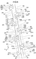
医療用長尺体10は、図1に示すように、長尺であって回転駆動されるシャフト部20と、シャフト部20を収容できる外シース30と、シャフト部20によって回転する破砕部40とを備えている。医療用長尺体10は、さらに、シャフト部20を回転させる駆動源(例えば、モータ)を備える回転駆動部50と、シャフト部20の近位側端部に設けられるハブ60とを備えている。破砕部40は、弾性的に変形可能な複数の線材である。なお、破砕部40の構成は、管腔内の物質を破砕できれば特に限定されない。管腔は血管、動脈、静脈、脈管等がある。物質は、血栓、プラーク、繊維状物質や石灰化物質、繊維状になった血管や石灰化した血管等があるが特に限定されない。
シャフト部20は、回転駆動部50により回転駆動される外管シャフト21と、外管シャフト21の内側に配置され、近位部にハブ60が固着される内管シャフト22とを備えている。外管シャフト21は、柔軟性を得つつ回転駆動力を伝達できるように、螺旋状のスリット71が設けられた管状体70を備えている。
管状体70は、図2~6に示すように、螺旋状のスリット71が設けられた先端側の柔軟部72と、スリット71が形成されていない基端側の高剛性部73とを備えている。スリット71は、レーザー加工等の一般的に行われる技術を用いてスパイラルスリット加工により形成される。
柔軟部72は、所定のピッチL1でスリット71が設けられている。スリット71は、管状体70の外周面から内周面へ貫通する線状の切り込みである。スリット71は、管状体70に後述する凸部や凹部を構成するように湾曲しつつ螺旋を描くように連続する。ピッチL1は、スリット71が、周方向に360度を巻回することで管状体70の軸方向Xに移動する距離を意味する。管状体70の柔軟部72は、スリット71が形成されることで、曲げ剛性が低減されて曲がりやすい柔軟な構造となっている。なお、螺旋状のスリットが複数設けられることで、管状体70は、多重螺旋構造で構成されてもよい。柔軟部72は、軸方向Xに並ぶスリット71の間に、帯状の板材である1つの帯部200を有している(図6を参照)。帯部200は、螺旋を描いて柔軟部72を構成している。なお、管状体70が多重螺旋構造である場合には、柔軟部は、複数の帯部により構成される。
スリット71は、対向して配置される対をなす対向面100、110により構成されている。対をなす対向面100、110の第1の側に、対向面100(または対向面110)が位置し、第2の側に、対向面110(または対向面100)が位置している。対向面の第1の側は、近位側、遠位側または周方向側であり得る。対向面の第2の側は、第1の側の反対側である。対向面100は、軸方向に並ぶ2つのスリット71の間に位置する螺旋状の構造体の、近位側の端面(第1の側)である。対向面100は、管状体70の内周面と外周面を繋ぐ面である。対向面100は、スリット71の間に位置する螺旋状の構造体に沿って、周方向に延びている。対向面110は、軸方向に並ぶ2つのスリット71の間に位置する螺旋状の構造体の、遠位側の端面(第2の側)である。対向面110は、管状体70の内周面と外周面を繋ぐ面である。対向面110は、スリット71の間に位置する螺旋状の構造体に沿って、周方向に延びている。対向面100と対向面110は、スリット71を挟んで隣接する(対面する)。遠位側の対向面100には、近位側へ突出する第1の凸部101および第3の凸部102が複数設けられている。近位側の対向面110には、第1の凸部101が入り込む第1の凹部111(凹部)と、第3の凸部102が入り込む第3の凹部112(凹部)が、複数設けられている。第1の凸部101は、第1の凹部111に引っ掛かり、管状体70の軸方向Xおよび周方向Yへの相対的な移動が制限される。第3の凸部102は、第3の凹部112に引っ掛かり、軸方向Xおよび周方向Yへの相対的な移動が制限される。
スリット71は、管状体70において湾曲しながら螺旋を描くことで、平行な3つの第1の螺旋81、第2の螺旋82または第3の螺旋83に位置することができる。第1の螺旋81、第2の螺旋82および第3の螺旋83の各々は、軸方向に沿って一定のピッチで螺旋を描いている。したがって、第1の螺旋81、第2の螺旋82および第3の螺旋83は、管状体70の軸心に対して一定の螺旋角度を有している。第1の螺旋81には、第3の凸部102の頂部102Aおよび第1の凸部101の基部101Bが位置する。第2の螺旋82には、第1の凸部101の頂部101Aが位置する。第3の螺旋83には、第3の凸部102の基部102Bが位置する。スリット71が複数の螺旋(第1の螺旋81、第2の螺旋82または第3の螺旋83)に位置することによって、管状体70は、螺旋のそれぞれを関節として曲がりやすくなり、柔軟となる。
また、第1の凸部101の頂部101Aには、直線状の第1の端面101Eが設けられる。周方向Yに並ぶ複数の第1の端面101Eは、第2の螺旋82に位置する。また、第3の凸部102の頂部102Aには、直線状の第3の端面102Eが設けられる。周方向Yに並ぶ複数の第3の端面102Eは、第1の螺旋81に位置する。
第1の凸部101は、突出側(近位側)で幅が広がる第1の幅広部101Fを有している。第1の幅広部101Fは、螺旋の延在方向(周方向Y)の両側へ突出する2つの第1の張出部101Cを有する。また、第1の凸部101は、一方の第1の張出部101Cと第3の螺旋83の間に、周方向の幅が段差状に変化する段差部101Dを有している。また、第3の凸部102は、突出側(近位側)で幅が広がる第3の幅広部102Fを有している。第3の幅広部102Fは、螺旋の延在方向(周方向Y)の両側へ突出する2つの第3の張出部102Cを有する。第1の凸部101や第3の凸部102の突出側は、遠位側や周方向側でもよい。
第1の凸部101の周方向Yの最大幅B1は、第3の凸部102の周方向Yの最小幅B2よりも短い。そして、第1の凸部101の突出側に隣接するスリット71に、第1の凸部101と軸方向Xに重なるように第3の凸部102が配置されている。このため、第1の凸部101の突出側に、周方向Yの長さが長い第3の凸部102が位置することになる。第1の凸部101の最大幅B1は、周方向Yにおいて、第1の凸部101の突出側に隣接する第3の凸部102の最小幅B2の範囲内に位置する。したがって、軸方向Xに隣接するスリット71とスリット71の間隔が部分的に狭くなることを抑制でき、破損の発生を抑制できる。また、管状体70は、スリット71とスリット71の間隔が部分的に狭くなることを抑制できるため、曲がりやすい位置が周方向Yに偏り難くなり、適切な強度を確保できる。
近位側の対向面110には、遠位側へ突出する第2の凸部113および第4の凸部114が複数設けられている。遠位側の対向面100には、第2の凸部113が入り込む第2の凹部103(凹部)と、第4の凸部114が入り込む第4の凹部104(凹部)が、複数設けられている。第2の凸部113は、第2の凹部103に引っ掛かり、軸方向Xおよび周方向Yへの相対的な移動が制限される。第4の凸部114は、第4の凹部104に引っ掛かり、軸方向Xおよび周方向Yへの相対的な移動が制限される。
第1の螺旋81には、第2の凸部113の基部113Bおよび第4の凸部114の頂部114Aが位置する。頂部114Aには、直線状の第4の端面114Eが設けられる。第3の螺旋83には、第2の凸部113の頂部113Aが位置する。頂部113Aには、直線状の第2の端面113Eが設けられる。第2の螺旋82には、第4の凸部114の基部114Bが位置する。
第2の凸部113は、突出側(遠位側)で幅が広がる第2の幅広部113Fを有している。第2の幅広部113Fは、螺旋の延在方向(周方向Y)の両側へ突出する2つの第2の張出部113Cを有する。また、第2の凸部113は、一方の第2の張出部113Cに、周方向の幅が段差状に変化する段差部113Dを有している。また、第4の凸部114は、突出側(遠位側)で幅が広がる第4の幅広部114Fを有している。第4の幅広部114Fは、螺旋の延在方向(周方向Y)の両側へ突出する2つの第4の張出部114Cを有する。
第1の螺旋81は、スリット71が存在する比率が最も高い螺旋(基本螺旋)である。スリット71が存在する比率が高い基本螺旋が存在することで、柔軟性に対する方向性の偏りを極力少なくすることができる。第2の螺旋82および第3の螺旋83は、第1の螺旋81を挟んでいる。第1の螺旋81と第2の螺旋82の間の軸方向Xへの距離L2は、第1の螺旋81と第3の螺旋83の間の軸方向Xへの距離L3と等しい。なお、距離L2および距離L3は、異なってもよい。距離L2および距離L3は、第1の螺旋81(基本螺旋)のピッチL1の半分以下であることが好ましいが、これに限定されない。距離L2および距離L3が基本螺旋のピッチL1の半分以下であると、軸方向Xに並ぶ2つのスリット71の間の間隔が狭くなり過ぎる部位が生じる可能性を抑制し、2つのスリット71の間の材料の幅を維持できる。これにより、管状体70は、適切な強度を確保できる。また、距離L2および距離L3は、第1の凸部101、第3の凸部102、第2の凸部113および第4の凸部114の強度を確保できるように、小さ過ぎずにある程度の長さが確保されることが好ましい。ピッチL1は、特に限定されないが、例えば0.5mm~2.5mmである。距離L2および距離L3は、特に限定されないが、例えば0.25mm~1.25mmである。
遠位側の対向面100において、2つの第1の凸部101のセットと、1つの第3の凸部102が、螺旋に沿って交互に並んで配置される。また、近位側の対向面110において、2つの第2の凸部113のセットと、1つの第4の凸部114が、螺旋に沿って交互に並んで配置される。
遠位側の対向面100の第1の凸部101と、近位側の対向面110の第2の凸部113は、周方向Yに隣接して対となって配置される。隣接する第1の凸部101および第2の凸部113により構成される凸部群120は、基本螺旋に沿って周方向Yに240度毎に設けられる。周方向Yに隣り合う凸部群120は、第1の凸部101および第2の凸部113の配置が周方向Yに入れ替わっている。したがって、周方向Yに隣り合う2つの凸部群120は、展開図において、2つの凸部群120の中央に位置して螺旋と直交する直交線Zに対して線対称となっている。
また、各凸部群120の隣接する第1の凸部101および第2の凸部113は、展開図において、段差部101Dの近傍に位置する点に対して点対称形状である。すなわち、第1の凸部101および第2の凸部113は、大きさおよび形状が同一であり、向きのみが異なる。したがって、第2の凸部113は、第1の凸部101と向きが異なる同様の構成を備えている。なお、大きさが同一とは、寸法が同一であることを意味する。また、形状が同一とは、展開図において形状が相似関係にあることを意味する。
凸部群120は、第1の螺旋81(基本螺旋)に沿って周方向Yに240度毎に位置する。このため、凸部群120は、巻回することで軸方向Xに隣り合う2つのスリット71において、軸方向Xに沿って並ばない。凸部群120は、周方向Yに240度毎に位置するため、軸方向Xに1つのスリット71を挟みつつ並ぶ。軸方向Xに1つのスリット71を挟んで並ぶ2つの凸部群120は、第1の凸部101および第2の凸部113の配置が周方向Yに逆となっている。
管状体70の構成材料は、比較的剛性の高い材質であることが好ましく、例えばNi-Ti、真鍮、SUS、アルミ等の金属を用いることが好ましい。なお、比較的剛性の高い材質であれば、管状体70の構成材料は特に限定されず、例えばポリイミド、塩化ビニル、ポリカーボネート等の樹脂であってもよい。
管状体70の寸法は、特に限定されない。例えば、管状体70の外径は約0.5mm~3.5mm、肉厚は約10μm~500μm、長さは約100mm~5000mmである。
スリット71の隙間(対向面100と対向面110の離間距離)は、特に限定されないが、例えば約0.01mm~0.05mmである。
次に、本実施形態に係る医療用長尺体10の使用方法を、静脈内の物質を破砕して吸引する場合を例として説明する。
本実施形態の医療用長尺体10を使用する際には、破砕部40を含むシャフト部20の遠位部が、外シース30に納められた状態の医療用長尺体10を準備する。破砕部40は、外シース30内で弾性的に変形して収縮している。
次に、ガイドワイヤ(図示せず)を血管内に挿入し、ガイドワイヤをガイドとして、医療用長尺体10を物質の近位側へ到達させる。この後、外シース30をシャフト部20に対して近位側へ移動させると、破砕部40が外シース30の外部に露出し、自己の弾性力により拡張する。
次に、破砕部40が物質の近傍まで進入した状態で、回転駆動部50によりシャフト部20を回転させると、破砕部40もそれに伴って回転する。この状態で破砕部40を血管内で移動させると、破砕部40が物質に接触し、破砕部40が血管内で固着した状態の物質を破砕する。破砕部40の回転は、往復回転であるが、一方向へ連続的に回転してもよい。
次に、ハブ60にシリンジを連結して押し子を引いて、シャフト部20の中空内部を負圧状態とする。これにより、シャフト部20の遠位部に位置する開口部23から、血管内を浮遊する破砕された物質を吸引して血管外に排出できる。物質の吸引が完了した後、回転駆動部50を操作して回転動を停止する。この後、破砕部40を外シース30に収容して収縮させ、医療用長尺体10を血管から抜去し、手技が完了する。
なお、外シース30の手元部に側孔を設けて、その側孔にシリンジを連結して外シース30の先端から物質を吸引することも可能である。また、物質を破砕した後、外シース30から破砕部40とシャフト部20を引き抜き、外シース30のハブにシリンジを連結して物質を吸引することも可能である。
以上のように、実施形態に係る医療用長尺体10は、螺旋状のスリット71が設けられた管状体70を有し、管状体70は、スリット71の両側に対をなす対向面100、110を有し、対向面は第1の側と前記第1の側に対してスリット71を挟んで反対側に第2の側を有し、第1の側から第1の凸部101が突出するとともに、第2の側から第2の凸部113が突出し、第1の凸部101および第2の凸部113は管状体70の周方向に隣接し、第1の凸部101および第2の凸部113の基部101B、113Bは共通の第1の螺旋81(螺旋)上に位置する。第1の螺旋81は、スリット71が存在する比率が最も高い螺旋(基本螺旋)である。第1の螺旋81は、管状体70の軸心に対して一定の螺旋角度を有している。なお、対向面の第1の側は、近位側、遠位側または周方向側であり得る。対向面の第2の側は、第1の側の反対側である。上記のように構成した医療用長尺体10は、第1の凸部101および第2の凸部113の基部101B、113Bが共通の第1の螺旋81上に位置するため柔軟性が高い。また、対向面100、110に、隣接する第1の凸部101および第2の凸部113が設けられることで、医療用長尺体10は、回転力が2つの第1の凸部101および第2の凸部113に分散して均一に作用する。このため、医療用長尺体10は、捩れを抑制してトルク伝達性が向上するとともに、応力を分散して破損の発生を抑制できる。特に、管状体70は、回転して回転力を伝達させるための部材であるため、捩れを抑制できることで、操作性を向上できる。また、医療用長尺体10は、トルク伝達能力が向上することで、破砕部40において破砕時に過度の抵抗を受けた場合に、抵抗が近位側へ効果的に伝わり、緊急停止することが可能である。
また、周方向に隣接する第1の凸部101および第2の凸部113は、周方向展開図において点対称形状である。これにより、医療用長尺体10は、回転力が第1の凸部101および第2の凸部113にバランス良く分散するため、トルク伝達性が向上するとともに、破損の発生をさらに抑制できる。
また、第1の凸部101および第2の凸部113は、突出側で周方向の幅が広がっている。これにより、第1の凸部101が対向面110側と引っ掛かり、第2の凸部113が対向面100側と引っ掛かる。このため、管状体70は、軸方向Xおよび周方向Yの両方向へ引っ掛かりが生じて伸びや捩れを抑制できる。
また、隣接する第1の凸部101および第2の凸部113を含む凸部群120は、周方向に並んで配置される他の凸部群120に対して、第1の凸部101および第2の凸部113の配置が周方向に逆となっている。これにより、第1の凸部101および第2の凸部113の配置の偏りを抑制し、周方向Yへの柔軟性の偏りを低減できる。
また、第1の凸部101および第2の凸部113は、突出方向に向かって2段階以上で段差的に幅が広がっている。これにより、第1の凸部101および第2の凸部113は、互いに引っ掛かりやすくなる。このため、医療用長尺体10は、伸びや捩れをさらに抑制できる。
また、第1の凸部101の突出側の第1の端面101Eおよび第2の凸部113の突出側の第2の端面113Eは、第1の凸部101および第2の凸部113の基部が共通して位置する第1の螺旋81(基本螺旋)と平行である。これにより、管状体70は、第1の螺旋81のみならず、第1の端面101E(第2の螺旋82)の位置と、第2の端面113E(第3の螺旋83)の位置でも曲がることが容易となる。したがって、管状体70は、柔軟性が増加するとともに操作性が向上する。
また、第1の凸部101および第2の凸部113は、軸方向Xに隣接するスリット71に設けられる他の第1の凸部101および第2の凸部113と周方向Yへ異なる位置に配置される。これにより、第1の凸部101および第2の凸部113が軸方向Xに連続して配置されない。このため、管状体70は、柔軟性が周方向Yに偏り難くなり、曲がる位置の調節が容易となって操作性が向上する。
また、第1の側は第2の側に向かって突出する第3の凸部102をさらに有し、第1の凸部101は第2の側に突出するとともに、突出側で幅が広がっている第1の幅広部101Fを有し、第3の凸部102は第2の側に突出するとともに、突出側で幅が広がっている第3の幅広部102Fを有し、対向面の第2の側は第1の凸部101および第3の凸部102を囲むように収容する第1の凹部111および第3の凹部112を有し、第1の凸部101および第3の凸部102は、大きさおよび形状の少なくとも一方が異なる。なお、対向面の第1の側は、近位側、遠位側または周方向側であり得る。対向面の第2の側は、第1の側の反対側である。これにより、医療用長尺体10は、第1の凸部101の第1の幅広部101Fおよび第3の凸部102の第3の幅広部102Fが、第1の凹部111および第3の凹部112に対して軸方向Xおよび周方向Yの両方向へ引っ掛かる。このため、医療用長尺体10は、軸方向Xへの伸びと捩れの発生を抑制してトルク伝達性が向上する。また、第1の凸部101および第3の凸部102は、大きさおよび形状の少なくとも一方が異なるため、形状の偏り(異方性)が少なくなり、周方向Yへの柔軟性の偏りを低減できる。特に、管状体70は、回転して回転力を伝達させるための部材であるため、周方向へ極力偏りのない柔軟性を保持することで、周方向によるトルク伝達性の異方性を極力抑えて操作性を向上できる。なお、ここでは、遠位側の対向面100の第1の凸部101および第3の凸部102が、近位側の対向面110の第1の凹部111および第3の凹部112に収容される構成について説明している。しかしながら、近位側の対向面110の第2の凸部113および第4の凸部114が、遠位側の対向面100の第2の凹部103および第4の凹部104に収容される構成についても、同様の効果を有する。また、医療用長尺体10は、トルク伝達能力が向上することで、破砕部40において破砕時に過度の抵抗を受けた場合に、抵抗が近位側へ効果的に伝わり、緊急停止することが容易となって安全性が向上する。なお、第1の幅広部101Fは、第3の幅広部102Fと同じ形状や大きさでもよく、異なってもよい。
また、周方向Yに隣接する第1の凸部101および第3の凸部102の突出方向端部は、管状体70に沿って巻回する異なる螺旋上に位置する。これにより、管状体70は、第1の凸部101の突出方向端部の位置と、第3の凸部102の突出方向端部の位置の両方で曲がることができ、柔軟性が増加する。
また、第1の凸部101の突出側の第1の端面101Eおよび第3の凸部102の突出側の第3の端面102Eは、第1の凸部101および第3の凸部102の少なくとも一方の基部が位置する螺旋状に巻回する第3の螺旋83(螺旋)と平行である。これにより、管状体70は、第1の端面101Eの位置と、第3の端面102Eの位置で曲がる際に抵抗が小さくなり、柔軟性が増加するとともに操作性が向上する。
また、複数の第1の端面101Eが並ぶ第2の螺旋82(螺旋)は、複数の第3の端面102Eが並ぶ第1の螺旋81(螺旋)と異なる位置に配置される。これにより、管状体70は、第1の端面101Eの位置と、第3の端面102Eの位置の両方で曲がることができ、柔軟性が増加する。
また、第1の凸部101は、軸方向Xに隣接するスリット71に設けられる他の第1の凸部101と周方向Yへ異なる位置に配置される。これにより、第1の凸部101が軸方向Xに連続して配置されないため、管状体70は、柔軟性が周方向Yに偏り難くなり、曲がる位置の調節が容易となって操作性が向上する。
また、第1の凸部101は、第3の凸部102よりも周方向Yの長さが短く、第1の凸部101の突出側に隣接するスリット71に、第1の凸部101と軸方向Xに重なるように第3の凸部102が位置する。これにより、第1の凸部101の突出側に周方向Yの長さが長い第3の凸部102が位置することになるため、軸方向Xに隣接する2つのスリット71の間隔が部分的に狭くなることを抑制できる。したがって、管状体70は、曲がりやすい位置が周方向Yに偏り難くなり、かつ適切な強度を確保できる。
また、第1の凸部101の周方向Yの最大幅B1は、第3の凸部102の周方向Yの最小幅B2よりも短く、第1の凸部101の突出側に隣接するスリット71に、第1の凸部101と軸方向Xに重なるように第3の凸部102が配置されている。これにより、第1の凸部101の突出側に周方向Yの長さが長い第3の凸部102が位置することになるため、軸方向Xに隣接するスリット71の間隔が部分的に狭くなることを抑制できる。したがって、管状体70は、曲がりやすい位置が周方向Yに偏り難くなり、かつ適切な強度を確保できる。
また、周方向に隣り合う第1の凸部101および第3の凸部102は、当該第1の凸部101および第3の凸部102の周方向Yの配置が交互に入れ替わりつつスリット71に沿って周方向Yに並んで配置されている。これにより、管状体70は、曲がりやすい位置が周方向Yに偏り難くなり、曲がる位置の調節が容易となって操作性が向上する。
また、実施形態に係る医療用長尺体10は、図6に示すように、螺旋状に延びる板材である帯部200が設けられた管状体70を有する医療用長尺体10であって、帯部200は、管状体70の内面側に位置する内周面、管状体70の外面側に位置する外周面、内周面および外周面を連結する2つの側面を有し、側面は、山形状201と、谷形状202と、直線形状203とを有し、山形状201および谷形状202は隣接し、隣接した山形状201および谷形状202を含む凸凹部204を複数有し、直線形状203が凸凹部204を結んでいる。上記のように構成した医療用長尺体10は、帯部200の側面に、隣接する山形状201および谷形状202が設けられることで、医療用長尺体10に作用する回転力が、2つの山形状201(山形状201および当該山形状201と隣接する谷形状202に収容される他の山形状201)に分散して均一に作用する。このため、医療用長尺体10は、捩れを抑制してトルク伝達性が向上するとともに、応力を分散して破損の発生を抑制できる。特に、管状体70は、回転して回転力を伝達させるための部材であるため、捩れを抑制できることで、操作性を向上できる。また、医療用長尺体10は、トルク伝達能力が向上することで、破砕部40において破砕時に過度の抵抗を受けた場合に、抵抗が近位側へ効果的に伝わり、緊急停止することが可能である。
また、山形状201および谷形状202は、山の頂部側または谷の底側で、帯部200の延在方向の幅が広がっている。このため、山形状201が、山形状201を収容する谷形状202に対して軸方向Xおよび周方向Yの両方向へ引っ掛かる。このため、医療用長尺体10は、軸方向Xへの伸びと捩れの発生を抑制してトルク伝達性が向上する。
また、山形状201および谷形状202は、帯部200が螺旋状に配置されることで嵌り合っている。このため、山形状201が、当該山形状201を収容する谷形状202に対して軸方向Xおよび周方向Yの両方向へ引っ掛かりやすい。このため、医療用長尺体10は、軸方向Xへの伸びと捩れの発生を抑制してトルク伝達性が向上する。
また、山形状201および谷形状202は、略同一形状である。このため、山形状201が谷形状202に対して良好に嵌合できる。したがって、山形状201および谷形状202は、軸方向Xおよび周方向Yの両方向へ引っ掛かりやすい。このため、医療用長尺体10は、軸方向Xへの伸びと捩れの発生を抑制してトルク伝達性が向上する。
また、山形状201は頂面201A、谷形状202は底面202Aを有し、管状体の周方向展開図において、直線形状203が位置する第1の線S1、頂面201Aが位置する第2の線S2、および底面202Aが位置する第3の線S3は、位置が異なる。これにより、管状体70は、第1の線S1、第2の線S2および第3の線S3の位置で曲がりやすくなり、柔軟性が増加する。なお、第1の線S1は、第1の螺旋81に対応する位置に設けられる。第2の線S2は、第2の螺旋82に対応する位置に設けられる。第3の線S3は、第3の螺旋83に対応する位置に設けられる。
なお、本発明は、上述した実施形態のみに限定されるものではなく、本発明の技術的思想内において当業者により種々変更が可能である。例えば、図7に示すように、第1の変形例である管状体130は、スリット131の巻回方向が上記の実施形態と逆方向であってもよい。
また、図8に示すように、第2の変形例である管状体140は、各々の第1の凸部141に設けられる2つの張出部142、143の形状が異なり、かつ第2の凸部144に設けられる2つの張出部145、146の形状が異なってもよい。なお、同様の機能を有する部位には同一の符号を付し、説明を省略する。
また、図9に示すように、第3の変形例である管状体150は、各々の第1の凸部151に2つではなく1つの張出部152を有し、第2の凸部153に1つの張出部154を有してもよい。
また、図10に示すように、第4の変形例である管状体160は、向かい合う対向面161、162に設けられて隣接する第1の凸部163および第2の凸部164の配置が、周方向に反転して配置されず、常に同じ配置であってもよい。
また、図11に示すように、第5の変形例である管状体170は、スリット171のピッチL1が軸方向Xに沿って変化してもよい。例えば、遠位側へ向かってスリット171のピッチL1を漸次的に狭くすることで、遠位側ほど曲げ剛性を低くすることができる。これにより、管状体170は、曲げ剛性が高い近位側の部位によって十分な押し込み性を確保できるとともに、柔軟な遠位側の部位によって、生体管腔の湾曲部位をも容易に通過でき、高い到達性および操作性を同時に得られる。第1の螺旋81、第2の螺旋82および第3の螺旋83は、スリット171と同様に、軸方向に沿って漸次的に変化する。また、軸方向Xの位置によって、第1の凸部172、第2の凸部174、第3の凸部173および第4の凸部175の大きさや形状が異なってもよい。例えば、ピッチL1の大きい近位部では、ピッチL1に余裕があるため、第1の凸部172、第2の凸部174、第3の凸部173および第4の凸部175を大きくすることができる。スリット171のピッチL1は、傾斜的に変化してもよい。これにより、管状体は、より高い到達性および操作性を得ることができ、かつ応力が1カ所に集中することがなく、破損やキンクの発生を低減できる。また、スリットのピッチL1は、近位側ほど短くてもよい。また、第1の凸部、第2の凸部、第3の凸部および第4の凸部の大きさや形状が、近位側ほど小さくてもよい。
また、図12に示すように、第6の変形例である管状体180は、第1の凸部181、第3の凸部182、第2の凸部183および第4の凸部184に、幅が広がる幅広部が設けられなくてもよい。
また、本実施形態に係る医療用長尺体10は、静脈内で血栓を除去するためのデバイスであるが、医療用の長尺体であれば特に限定されない。例えば、医療用長尺体は、動脈内で石灰化した病変部を削り取るためのアテレクトミーデバイスや、マイクロカテーテル、イメージングカテーテル等の他の用途のカテーテル、ガイドワイヤ等であってもよい。
また、管状体の第1の凸部および第3の凸部は、規則性を持って配置されなくてもよく、ランダムに配置されてもよい。これにより、管状体の曲げ剛性の周方向へ異方性を減少できる。なお、管状体の第1の凸部および第3の凸部は、規則性を持って配置されることで、曲げ方向を計画的に調節することができる。
さらに、本出願は、2016年7月20日に出願された日本特許出願番号2016-142312号および日本特許出願番号2016-142313号に基づいており、それらの開示内容は、参照され、全体として、組み入れられている。
10 医療用長尺体、
20 シャフト部、
70、130、140、150、160、170、180 管状体、
71 スリット、
81 第1の螺旋、
82 第2の螺旋、
83 第3の螺旋、
100、110、161、162 対向面、
101、141、151、163、172、181 第1の凸部、
102、173、182 第3の凸部、
101A、102A、113A、114A 頂部、
101B、102B、113B、114B 基部、
101D、113D 段差部、
101E 第1の端面、
101F 第1の幅広部、
102E 第3の端面、
102F 第3の幅広部、
103 第2の凹部(凹部、溝部)、
104 第4の凹部(凹部)、
111 第1の凹部(凹部)、
112 第3の凹部(凹部)、
113、144、153、164、174、183 第2の凸部、
113E 第2の端面、
113F 第2の幅広部、
114、175、184 第4の凸部、
114E 第4の端面、
114F 第4の幅広部、
120 凸部群、
131、171 スリット、
200 帯部、
201 山形状、
201A 頂面、
202 谷形状、
202A 底面、
203 直線形状、
204 凸凹部、
B1 最大幅、
B2 最小幅、
L1 ピッチ、
L2 距離、
L3 距離、
S1 第1の線、
S2 第2の線、
S3 第3の線、
X 軸方向、
Y 周方向、
Z 直交線。
Claims (18)
- 螺旋状のスリットが設けられた管状体を有する医療用長尺体であって、
前記管状体は、前記スリットの両側に対をなす対向面を有し、
前記対向面は第1の側と前記第1の側に対して前記スリットを挟んで反対側に位置する第2の側を有し、
前記第1の側から第1の凸部が突出するとともに、前記第2の側から第2の凸部が突出し、前記第1の凸部および第2の凸部は前記管状体の周方向に隣接し、前記第1の凸部および第2の凸部の基部は共通の螺旋上に位置する医療用長尺体。 - 周方向に隣接する前記第1の凸部および第2の凸部は、周方向展開図において点対称形状である請求項1に記載の医療用長尺体。
- 前記第1の凸部および第2の凸部は、突出側で周方向の幅が広がっている請求項1または2に記載の医療用長尺体。
- 隣接する前記第1の凸部および第2の凸部を含む凸部群は、周方向に並んで配置される他の凸部群に対して、前記第1の凸部および第2の凸部の配置が周方向に逆となっている請求項1~3のいずれか1項に記載の医療用長尺体。
- 前記第1の凸部および第2の凸部は、突出方向に向かって2段階以上で段差的に幅が広がっている請求項1~4のいずれか1項に記載の医療用長尺体。
- 前記第1の側は前記第2の側に向かって突出する第3の凸部をさらに有し、
前記第1の凸部は前記第2の側に突出するとともに、突出側で幅が広がっている第1の幅広部を有し、
前記第3の凸部は前記第2の側に突出するとともに、突出側で幅が広がっている第3の幅広部を有し、
前記対向面の第2の側は前記第1の凸部および第3の凸部を囲んで収容する凹部を有し、
前記第1の凸部および第3の凸部は、大きさおよび形状の少なくとも一方が異なる請求項1~5のいずれか1項に記載の医療用長尺体。 - 周方向に隣接する前記第1の凸部および第3の凸部の突出方向端部は、前記管状体に沿って巻回する異なる螺旋上に位置する請求項6に記載の医療用長尺体。
- 前記第1の凸部の突出側の第1の端面および前記第3の凸部の突出側の第3の端面は、前記第1の凸部および第3の凸部の少なくとも一方の基部が位置する螺旋状に巻回する螺旋と平行である請求項6または7に記載の医療用長尺体。
- 複数の前記第1の端面が並ぶ螺旋は、複数の前記第3の端面が並ぶ螺旋と異なる位置に配置される請求項8に記載の医療用長尺体。
- 前記第1の凸部は、軸方向に隣接するスリットに設けられる他の第1の凸部と周方向に異なる位置に配置される請求項6~9のいずれか1項に記載の医療用長尺体。
- 前記第1の凸部は、前記第3の凸部よりも周方向の長さが短く、前記第1の凸部の突出側に隣接するスリットに、前記第1の凸部と軸方向に重なる前記第3の凸部が設けられる請求項6~10のいずれか1項に記載の医療用長尺体。
- 前記第1の凸部の周方向の最大幅は、前記第3の凸部の周方向の最小幅よりも短く、前記第1の凸部の突出側に隣接するスリットに、前記第1の凸部と軸方向に重なるように第3の凸部が配置されている請求項11に記載の医療用長尺体。
- 周方向に隣り合う前記第1の凸部および第3の凸部は、当該第1の凸部および第3の凸部の周方向の配置が交互に入れ替わりつつ前記スリットに沿って周方向に並んで配置されている請求項6~12のいずれか1項に記載の医療用長尺体。
- 螺旋状に延びる板材である帯部が設けられた管状体を有する医療用長尺体であって、
前記帯部は、2つの側面を有し、
前記側面は、山形状と、谷形状と、直線形状と、を有し、
前記山形状および谷形状は隣接し、前記隣接した山形状および谷形状を含む凸凹部を複数有し、前記直線形状が前記凸凹部を結んでいる医療用長尺体。 - 前記山形状および谷形状は、山の頂部側または谷の底側で、前記帯部の延在方向の幅が広がっている請求項14に記載の医療用長尺体。
- 前記山形状および谷形状は、前記帯部が螺旋状に配置されることで嵌り合う請求項14または15に記載の医療用長尺体。
- 前記山形状および谷形状は、略同一形状である請求項14~16のいずれか1項に記載の医療用長尺体。
- 前記山形状は頂面、前記谷形状は底面を有し、
前記管状体の周方向展開図において、前記直線形状が位置する第1の線、前記頂面が位置する第2の線、および前記底面が位置する第3の線は、位置が異なる14~17のいずれか1項に記載の医療用長尺体。
Priority Applications (2)
| Application Number | Priority Date | Filing Date | Title |
|---|---|---|---|
| JP2018528834A JP6917372B2 (ja) | 2016-07-20 | 2017-07-19 | 医療用長尺体 |
| US16/251,528 US11013891B2 (en) | 2016-07-20 | 2019-01-18 | Medical elongated body |
Applications Claiming Priority (4)
| Application Number | Priority Date | Filing Date | Title |
|---|---|---|---|
| JP2016142313 | 2016-07-20 | ||
| JP2016-142313 | 2016-07-20 | ||
| JP2016-142312 | 2016-07-20 | ||
| JP2016142312 | 2016-07-20 |
Related Child Applications (1)
| Application Number | Title | Priority Date | Filing Date |
|---|---|---|---|
| US16/251,528 Continuation US11013891B2 (en) | 2016-07-20 | 2019-01-18 | Medical elongated body |
Publications (1)
| Publication Number | Publication Date |
|---|---|
| WO2018016529A1 true WO2018016529A1 (ja) | 2018-01-25 |
Family
ID=60992509
Family Applications (1)
| Application Number | Title | Priority Date | Filing Date |
|---|---|---|---|
| PCT/JP2017/026111 WO2018016529A1 (ja) | 2016-07-20 | 2017-07-19 | 医療用長尺体 |
Country Status (3)
| Country | Link |
|---|---|
| US (1) | US11013891B2 (ja) |
| JP (1) | JP6917372B2 (ja) |
| WO (1) | WO2018016529A1 (ja) |
Cited By (1)
| Publication number | Priority date | Publication date | Assignee | Title |
|---|---|---|---|---|
| WO2021065873A1 (ja) * | 2019-09-30 | 2021-04-08 | テルモ株式会社 | 医療デバイス |
Families Citing this family (3)
| Publication number | Priority date | Publication date | Assignee | Title |
|---|---|---|---|---|
| USD943743S1 (en) * | 2019-01-15 | 2022-02-15 | Olympus Corporation | Stone retrieval basket for medical device |
| US11478609B2 (en) * | 2019-09-26 | 2022-10-25 | Biosense Webster (Israel) Ltd. | Bendable guidewire |
| CN115104996A (zh) * | 2021-08-23 | 2022-09-27 | 深圳开立生物医疗科技股份有限公司 | 一种自适应弯曲管、内窥镜用弯曲管及内窥镜 |
Citations (4)
| Publication number | Priority date | Publication date | Assignee | Title |
|---|---|---|---|---|
| JPH11509752A (ja) * | 1995-07-18 | 1999-08-31 | エドワーズ,ガーランド,ユー. | 可撓性の軸 |
| JP2009540952A (ja) * | 2006-06-20 | 2009-11-26 | エーオーテックス, インコーポレイテッド | トルクシャフトおよびトルクドライブ |
| JP2014504890A (ja) * | 2010-10-05 | 2014-02-27 | ジンテス ゲゼルシャフト ミット ベシュレンクテル ハフツング | フレキシブル針を有する骨髄採取装置 |
| JP2015525611A (ja) * | 2012-06-28 | 2015-09-07 | エシコン・エンド−サージェリィ・インコーポレイテッドEthicon Endo−Surgery,Inc. | 可撓性駆動部材 |
Family Cites Families (1)
| Publication number | Priority date | Publication date | Assignee | Title |
|---|---|---|---|---|
| CN105142709B (zh) | 2013-04-26 | 2018-04-03 | 泰尔茂株式会社 | 医疗用长尺寸件 |
-
2017
- 2017-07-19 WO PCT/JP2017/026111 patent/WO2018016529A1/ja active Application Filing
- 2017-07-19 JP JP2018528834A patent/JP6917372B2/ja active Active
-
2019
- 2019-01-18 US US16/251,528 patent/US11013891B2/en active Active
Patent Citations (4)
| Publication number | Priority date | Publication date | Assignee | Title |
|---|---|---|---|---|
| JPH11509752A (ja) * | 1995-07-18 | 1999-08-31 | エドワーズ,ガーランド,ユー. | 可撓性の軸 |
| JP2009540952A (ja) * | 2006-06-20 | 2009-11-26 | エーオーテックス, インコーポレイテッド | トルクシャフトおよびトルクドライブ |
| JP2014504890A (ja) * | 2010-10-05 | 2014-02-27 | ジンテス ゲゼルシャフト ミット ベシュレンクテル ハフツング | フレキシブル針を有する骨髄採取装置 |
| JP2015525611A (ja) * | 2012-06-28 | 2015-09-07 | エシコン・エンド−サージェリィ・インコーポレイテッドEthicon Endo−Surgery,Inc. | 可撓性駆動部材 |
Cited By (1)
| Publication number | Priority date | Publication date | Assignee | Title |
|---|---|---|---|---|
| WO2021065873A1 (ja) * | 2019-09-30 | 2021-04-08 | テルモ株式会社 | 医療デバイス |
Also Published As
| Publication number | Publication date |
|---|---|
| JPWO2018016529A1 (ja) | 2019-05-09 |
| US11013891B2 (en) | 2021-05-25 |
| JP6917372B2 (ja) | 2021-08-11 |
| US20190151615A1 (en) | 2019-05-23 |
Similar Documents
| Publication | Publication Date | Title |
|---|---|---|
| WO2018016529A1 (ja) | 医療用長尺体 | |
| US10213578B2 (en) | Catheter assembly | |
| JP5013380B2 (ja) | 医療用チューブ、及び、これを用いたカテーテル | |
| JP2009528903A (ja) | 可変剛性の医療器具用シャフト | |
| EP2767303A1 (en) | Catheter | |
| JP6121077B1 (ja) | 可撓管及び可撓管を用いる内視鏡 | |
| JP5897237B1 (ja) | 内視鏡 | |
| EP3646916A1 (en) | Catheter, separator, and suction system | |
| JP2004283461A (ja) | 先端偏向操作可能カテーテル | |
| JP6271098B1 (ja) | 医療用オーバーチューブ | |
| WO2014024302A1 (ja) | 内視鏡湾曲部構造 | |
| WO2022264669A1 (ja) | ガイドワイヤ | |
| JP6192951B2 (ja) | 作動部材、および医療器具 | |
| JP2012223207A (ja) | バルーンカテーテル | |
| WO2017154749A1 (ja) | 医療デバイス | |
| WO2014162441A1 (ja) | 作動部材、および医療器具 | |
| JP2013176488A (ja) | ガイドワイヤ | |
| JP6276522B2 (ja) | 位置決め医療機器 | |
| WO2021045134A1 (ja) | 可動シャフト及び可動シャフトを有する医療器具 | |
| EP3777728A1 (en) | Medical device | |
| US11383067B2 (en) | Medical elongated body | |
| WO2018034307A1 (ja) | 医療用長尺体 | |
| JP6929020B2 (ja) | カテーテル | |
| US20220087505A1 (en) | Endoscope apparatus and bending member for endoscope | |
| JP2012196498A (ja) | 医療用チューブ |
Legal Events
| Date | Code | Title | Description |
|---|---|---|---|
| 121 | Ep: the epo has been informed by wipo that ep was designated in this application |
Ref document number: 17831045 Country of ref document: EP Kind code of ref document: A1 |
|
| ENP | Entry into the national phase |
Ref document number: 2018528834 Country of ref document: JP Kind code of ref document: A |
|
| NENP | Non-entry into the national phase |
Ref country code: DE |
|
| 122 | Ep: pct application non-entry in european phase |
Ref document number: 17831045 Country of ref document: EP Kind code of ref document: A1 |