WO2018016402A1 - 免震支持装置 - Google Patents
免震支持装置 Download PDFInfo
- Publication number
- WO2018016402A1 WO2018016402A1 PCT/JP2017/025433 JP2017025433W WO2018016402A1 WO 2018016402 A1 WO2018016402 A1 WO 2018016402A1 JP 2017025433 W JP2017025433 W JP 2017025433W WO 2018016402 A1 WO2018016402 A1 WO 2018016402A1
- Authority
- WO
- WIPO (PCT)
- Prior art keywords
- plate
- vibration damping
- stacking direction
- load
- hollow portion
- Prior art date
- Legal status (The legal status is an assumption and is not a legal conclusion. Google has not performed a legal analysis and makes no representation as to the accuracy of the status listed.)
- Ceased
Links
Images




Classifications
-
- F—MECHANICAL ENGINEERING; LIGHTING; HEATING; WEAPONS; BLASTING
- F16—ENGINEERING ELEMENTS AND UNITS; GENERAL MEASURES FOR PRODUCING AND MAINTAINING EFFECTIVE FUNCTIONING OF MACHINES OR INSTALLATIONS; THERMAL INSULATION IN GENERAL
- F16F—SPRINGS; SHOCK-ABSORBERS; MEANS FOR DAMPING VIBRATION
- F16F1/00—Springs
- F16F1/36—Springs made of rubber or other material having high internal friction, e.g. thermoplastic elastomers
- F16F1/40—Springs made of rubber or other material having high internal friction, e.g. thermoplastic elastomers consisting of a stack of similar elements separated by non-elastic intermediate layers
-
- F—MECHANICAL ENGINEERING; LIGHTING; HEATING; WEAPONS; BLASTING
- F16—ENGINEERING ELEMENTS AND UNITS; GENERAL MEASURES FOR PRODUCING AND MAINTAINING EFFECTIVE FUNCTIONING OF MACHINES OR INSTALLATIONS; THERMAL INSULATION IN GENERAL
- F16F—SPRINGS; SHOCK-ABSORBERS; MEANS FOR DAMPING VIBRATION
- F16F15/00—Suppression of vibrations in systems; Means or arrangements for avoiding or reducing out-of-balance forces, e.g. due to motion
- F16F15/02—Suppression of vibrations of non-rotating, e.g. reciprocating systems; Suppression of vibrations of rotating systems by use of members not moving with the rotating systems
-
- F—MECHANICAL ENGINEERING; LIGHTING; HEATING; WEAPONS; BLASTING
- F16—ENGINEERING ELEMENTS AND UNITS; GENERAL MEASURES FOR PRODUCING AND MAINTAINING EFFECTIVE FUNCTIONING OF MACHINES OR INSTALLATIONS; THERMAL INSULATION IN GENERAL
- F16F—SPRINGS; SHOCK-ABSORBERS; MEANS FOR DAMPING VIBRATION
- F16F15/00—Suppression of vibrations in systems; Means or arrangements for avoiding or reducing out-of-balance forces, e.g. due to motion
- F16F15/02—Suppression of vibrations of non-rotating, e.g. reciprocating systems; Suppression of vibrations of rotating systems by use of members not moving with the rotating systems
- F16F15/04—Suppression of vibrations of non-rotating, e.g. reciprocating systems; Suppression of vibrations of rotating systems by use of members not moving with the rotating systems using elastic means
Definitions
- the present invention is an apparatus for reducing the vibration acceleration to a structure, particularly for a seismic energy attenuation, which is arranged between two structures to absorb the energy of relative horizontal vibration between the two structures.
- the present invention relates to a seismic isolation support device that reduces input acceleration and prevents damage to structures such as buildings and bridges.
- Seismic support devices are known.
- Such a seismic isolation support device supports the vertical load of the structure with the laminated body and the lead plug and also causes the horizontal vibration of the structure against one end in the laminating direction of the laminated body due to the earthquake to generate plasticity of the lead plug. While it is damped by deformation (shear deformation), the transmission of horizontal vibration at one end of the stack in the stacking direction due to an earthquake to the structure is suppressed by elastic deformation (shear deformation) of the stack. Yes.
- lead is press-fitted and filled into the hollow portion of the laminated body to obtain a lead plug, but is press-fitted and filled to be surrounded by the inner peripheral surface of the rigid layer and the elastic layer of the laminated body.
- the lead plug thus pressed is partially pushed back by the elasticity of the elastic layer, and this pushback generates an internal pressure in the lead plug.
- the generated internal pressure of the lead plug is not sufficient in relation to the rigidity of the elastic layer, in the seismic isolation operation of the seismic isolation support device, there is a gap between the outer peripheral surface of the lead plug and the inner peripheral surface of the rigid layer and the elastic layer. May occur, and vibration may not be effectively damped by the lead plug.
- Such a problem occurs remarkably in a lead plug, but is not limited to such a lead plug, and is a vibration damping body made of a damping material such as lead, tin, or a non-lead low melting point alloy that absorbs vibration energy by plastic deformation. But it can happen.
- the present invention was made in view of the above points, and as a result of being able to constrain the vibration damping body arranged in the hollow portion of the laminated body without a predetermined gap, stable seismic isolation characteristics can be obtained,
- a seismic isolation support device includes a laminated body having alternately laminated elastic layers and rigid layers, an upper plate and a lower plate attached to an upper end surface and a lower end surface of the laminated body, an elastic layer and a rigid layer, and A load in the laminating direction applied to the upper plate and having a vibration damping body surrounded by an upper plate and a lower plate and extending in a hollow portion extending in the laminating direction from the lower surface of the upper plate to the upper surface of the lower plate Is supported by the laminated body and the vibration damping body, and the surface pressure Pr from the vibration damping body to the upper plate based on the load in the lamination direction to be supported and the pressure receiving surface against the load of the laminated body based on the load.
- the vibration damping body is arranged in the hollow portion so that the ratio Pr / P0 with the surface pressure P0 is 1.00 or more (ratio Pr / P0 ⁇ 1.00).
- the seismic isolation support device also includes a laminate having elastic layers and rigid layers alternately laminated, an upper plate and a lower plate attached to the upper end surface and the lower end surface of the laminate, an elastic layer, and rigidity.
- the hollow part that is surrounded by the layer and the upper and lower plates and extends in the stacking direction from the lower surface of the upper plate to the upper surface of the lower plate is arranged without any gap with respect to the elastic layer, the rigid layer, and the upper and lower plates.
- the load in the stacking direction applied to the upper plate is supported by the stack and the vibration damping body, and the vibration damping body is supported by the load in the stacking direction.
- the seismic isolation support device further includes a laminate having elastic layers and rigid layers alternately laminated, an upper plate and a lower plate attached to the upper end surface and the lower end surface of the laminate, an elastic layer, and A laminate that includes a rigid layer and a vibration damping body that is surrounded by a top plate and a bottom plate and that extends in a laminating direction from the bottom surface of the top plate to the top surface of the bottom plate and is applied to the top plate
- the load in the direction is supported by the laminated body and vibration damping body, and the vibration in the direction perpendicular to the lamination direction of the upper plate relative to the lower plate is attenuated by plastic deformation of the vibration damping body, while orthogonal to the lamination direction of the lower plate Transmission to the upper plate in the direction of vibration is suppressed by shear elastic deformation of the laminated body, and the surface pressure Pr from the vibration damping body to the upper plate based on the load in the laminated direction to be supported and the load With the pressure P0 at the pressure-re
- the seismic isolation support device includes a laminate having elastic layers and rigid layers alternately laminated, an upper plate and a lower plate attached to the upper end surface and the lower end surface of the laminate, an elastic layer, and
- the hollow portion surrounded by the rigid layer and the upper and lower plates and extending in the stacking direction from the lower surface of the upper plate to the upper surface of the lower plate has no gap with respect to the elastic layer, the rigid layer, and the upper and lower plates.
- a vibration attenuating body disposed on the upper plate and supporting the load in the laminating direction applied to the upper plate by the laminated body and the vibration attenuating body, and generating vibration in a direction perpendicular to the laminating direction of the upper plate relative to the lower plate.
- the vibration damping body While the vibration damping body is damped by plastic deformation, the transmission to the upper plate in the direction orthogonal to the lamination direction of the lower plate is suppressed by the shear elastic deformation of the laminate, and the load in the supporting lamination direction
- the surface pressure Pr from the vibration damping body to the upper plate based on The vibration damping body is arranged in the hollow portion so that the ratio Pr / P0 to the pressure P0 at the pressure-receiving surface with respect to the load of the laminate based on the weight is 1.00 or more (ratio Pr / P0 ⁇ 1.00). It becomes.
- the vibration attenuator presses the inner peripheral surface of the elastic layer and partially protrudes in the direction perpendicular to the laminating direction (horizontal direction, that is, the shearing direction) on the elastic layer.
- the vibration damping body disposed in the hollow portion is set to a predetermined value.
- the ratio Pr / P0 between the surface pressure Pr and the surface pressure P0 is 1.00 or more (ratio Pr / P0 ⁇ 1.00), preferably 1.00. More preferably, it exceeds 1.09 (ratio Pr / P0 ⁇ 1.09), and even more preferably, 2.02 or more (ratio Pr / P0 ⁇ 2.
- the vibration attenuator is preferably densely arranged in the hollow portion so as to be 2.50 or more (ratio Pr / P0 ⁇ 2.50), the direction perpendicular to the stacking direction
- the vibration damping body arranged in the hollow portion can be restrained by the elastic layer, the rigid layer, the upper plate, and the lower plate without a predetermined gap, so that stable seismic isolation characteristics can be obtained.
- fatigue and damage to the elastic layer and vibration damping body can be avoided, and durability And it is possible to provide a particularly good seismic isolation support device to a seismic isolation effect, as well as manufacturability.
- the surface pressure Pr from the vibration damping body to the upper plate depends on the magnitude of the load from the structure, the degree of filling of the vibration damping body into the hollow portion, and the elasticity or rigidity of the elastic layer.
- the inner circumferential surface of the laminated body that defines the hollow portion has the vibration damping body appropriately bite into the elastic layer, and the position of the elastic layer Becomes an annular concave surface, and becomes an annular convex surface at the position of the rigid layer.
- the elastic layer and the rigid layer which define the hollow portion, the upper plate and the lower plate, and the outer peripheral surface of the vibration damping body in contact therewith are provided.
- Unstable seismic isolation characteristics because gaps are easily generated, and therefore gaps are easily generated between the elastic and rigid layers, the upper and lower plates, and the outer peripheral surface of the vibration damping body during operation of the seismic isolation support device. Will be shown. This is presumably because the vibration attenuating body is not constrained to the laminate without any gap in at least the shearing direction (horizontal direction), and the vibration attenuating body undergoes deformation other than shear deformation.
- the vibration damping body greatly bites into the elastic layer, and the elastic layer
- the inner peripheral surface of the material becomes excessively concave, and the shear stress between the elastic layer and the rigid layer in the vicinity of this part becomes too large, which accelerates the deterioration of the elastic layer and deteriorates the durability of the elastic layer.
- the vibration damping body arranged in the hollow part can be restrained by the elastic layer and the rigid layer and the upper plate and the lower plate without a predetermined gap, and stable seismic isolation characteristics can be obtained.
- the ratio Pr / P0 that can avoid the fatigue and damage of the vibration attenuating body and can obtain a seismic isolation support device that is particularly excellent in durability, seismic isolation effect and manufacturability is the seismic isolation support device of the present invention.
- a small vibration input can provide a high rigidity
- a large vibration input can provide a function exhibiting a low rigidity, that is, a so-called trigger function, and can cope with a large-amplitude earthquake motion particularly favorably. Is extremely excellent.
- the vibration damping body is preferably made of a damping material that absorbs vibration energy by plastic deformation, and the damping material is made of lead, tin, or a lead-free low melting point alloy (for example, a tin-zinc based alloy).
- a tin-containing alloy selected from a tin-bismuth alloy and a tin-indium alloy, such as a tin-bismuth alloy containing 42-43 wt% tin and 57-58 wt% bismuth. It may be.
- the upper plate includes an upper flange plate having an upper through hole, and an upper blocking member fixed to the upper flange plate in the upper through hole.
- the upper end surface of the vibration damping body in the stacking direction is in contact with the lower end surface of the upper closing plate in the stacking direction without a gap, and the outer peripheral surface of the upper end portion of the vibration damping body in the stacking direction is
- the upper flange plate defining the upper through hole is in contact with the inner peripheral surface without a gap.
- the uppermost rigid layer in the stacking direction is open on the upper surface and in the stacking direction.
- the first recess has a diameter larger than the diameter of the upper portion of the hollow portion and communicates with the upper portion of the hollow portion, and the upper plate has an opening at the lower surface and a diameter of the first recess.
- An upper flange plate having a second recess facing one recess, and being fitted to the upper flange plate in the second recess, while the uppermost rigid layer in the first recess.
- the upper outer peripheral surface of the vibration damping body in the stacking direction is in contact with the inner peripheral surface of the uppermost rigid layer that defines the upper portion of the hollow portion without any gap. is doing.
- the lower plate includes a lower flange plate having a lower through hole, and a lower blocking member fixed to the lower flange plate in the lower through hole.
- the lower end surface of the vibration damping body in the stacking direction is in contact with the upper end surface of the lower closing plate in the stacking direction without a gap, and the outer peripheral surface of the lower end portion of the vibration damping body in the stacking direction is ,
- the lowermost rigid layer in the stacking direction is open on the lower surface and in the stacking direction.
- the upper flange plate and the lower flange plate may have a circular or elliptical outer edge, or alternatively, a rectangular or rectangular outer edge.
- examples of the material for the elastic layer include natural rubber, silicon rubber, high damping rubber, urethane rubber, chloroprene rubber, and the like, preferably natural rubber, and each layer of the elastic layer is preferably It has a thickness of about 1 mm to 30 mm in an unloaded state (a state in which the load in the supporting lamination direction is not applied to the upper plate), but is not limited to this, and the material of the rigid layer is a steel plate , A fiber reinforced synthetic resin plate such as carbon fiber, glass fiber or aramid fiber, or a fiber reinforced hard rubber plate, etc., and each layer of the rigid layer may have a thickness of about 1 mm to 6 mm, The uppermost layer and the lowermost rigid layer may have a thickness of about 10 mm to 50 mm, but are not limited thereto, and in addition, the elastic layer and the rigid layer are also particularly in their number.
- Stable seismic isolation characteristics are obtained from the viewpoint of the load of the supporting structure, the amount of shear deformation (horizontal strain), the elastic modulus of the elastic layer, and the predicted magnitude of vibration acceleration to the structure. Accordingly, the number of elastic layers and rigid layers may be determined.
- the elastic body and the vibration damping body are preferably an annular body and a cylindrical body, but may have other shapes, for example, an ellipse or a rectangular body and an ellipse or a rectangular body.
- the seismic isolation support device may have a plurality of hollow portions, and a vibration damping body is arranged in each of the plurality of hollow portions, and the seismic isolation support device. May be configured.
- the ratio Pr / P0 does not have to be the same for each of the plurality of hollow portions, and the ratio Pr / P0 may be different, and the ratio Pr / P0 for each of the plurality of hollow portions is different. As described above, it is preferably 1.00 or more, but the ratio Pr / P0 may be 1.00 or more only for a part of the plurality of hollow portions.
- the vibration damping body arranged in the hollow portion of the laminate can be constrained without a predetermined gap, so that stable seismic isolation characteristics can be obtained, and in addition, the elastic layer and vibration damping of the laminate can be obtained. It is possible to provide a seismic isolation support device that can avoid fatigue and damage of the body and that is particularly excellent in durability, seismic isolation effect, and manufacturability.
- FIG. 1 is a cross-sectional explanatory view taken along the line II in FIG. 2 of an example of a preferred embodiment of the present invention.
- FIG. 2 is a partial cross-sectional plan view of the example shown in FIG.
- FIG. 3 is a partially enlarged cross-sectional explanatory view of the example shown in FIG.
- FIG. 4 is an explanatory diagram of test results of hysteresis characteristics of horizontal displacement and horizontal stress in the preferred embodiment 1 of the present invention.
- FIG. 5 is an explanatory diagram of test results of hysteresis characteristics of horizontal displacement and horizontal stress in the preferred embodiment 2 of the present invention.
- FIG. 6 is an explanatory diagram of test results of hysteresis characteristics of horizontal displacement and horizontal stress in the preferred embodiment 3 of the present invention.
- FIG. 7 is an explanatory diagram of test results of hysteresis characteristics of horizontal displacement and horizontal stress in the comparative example.
- the seismic isolation support device 1 of this example shown in FIGS. 1 to 3 includes a cylindrical outer peripheral surface 4 of the elastic layer 2 and the rigid layer 3 in addition to the plurality of elastic layers 2 and the rigid layer 3 that are alternately stacked.
- a cylindrical laminated body 7 having a cylindrical covering layer 6 covered with 5 and an annular upper end face 8 and lower end face 9 of the laminated body 7 in the laminating direction (which is also the vertical direction in this example)
- the upper plate 10 and the lower plate 11, the elastic layer 2 and the rigid layer 3, and the upper plate 10 and the lower plate 11 are surrounded by the upper plate 10 and the lower plate 12 to the upper surface 13 of the lower plate 11 in the stacking direction V.
- the extended hollow portion 14 is arranged without a gap with respect to the inner peripheral surface 15 of the elastic layer 2, the cylindrical inner peripheral surface 16 of the rigid layer 3, the lower surface 12 of the upper plate 10, and the upper surface 13 of the lower plate 11. And a lead plug 17 as a vibration damping body.
- the lowermost rigid layer 3 communicates with the upper portion 25 of the hollow portion 14 and is defined by a cylindrical inner peripheral surface 27 having an opening at the lower surface 26 and having the same diameter as the inner peripheral surface 22. Open in the recess 28 and also in the lower surface 26 and in the circumferential direction R A plurality of screw holes 29 arranged at equal angular intervals, and a diameter larger than the diameter of the inner peripheral surface 16 of the lowermost rigid layer 3 that defines the lower portion 30 of the hollow portion 14 in the stacking direction V.
- the recess 28 defined by the inner peripheral surface 27 having a communication with the lower portion 30 of the hollow portion 14 is arranged between the uppermost rigid layer 3 and the lowermost rigid layer 3 in the stacking direction V.
- the covering layer 6 having a thickness of about 5 mm and made of the same natural rubber as the elastic layer 2 and having a cylindrical outer peripheral surface 31 and an annular upper end surface 32 and lower end surface 33 has a cylindrical inner peripheral surface. 34 is vulcanized and bonded to the outer peripheral surfaces 4 and 5.
- the upper plate 10 has a disk-shaped upper flange plate 43 having a recess 41 on the lower surface 42 that has the same diameter as the recess 23 and faces the recess 23 in the stacking direction V, and an upper flange in the recess 41.
- An upper shear key 45 fitted to the uppermost rigid layer 3 in the recess 23 and having a circular lower surface 44, and fitted to the plate 43.
- the upper flange plate 43 having 46 includes a plurality of through-holes 47 arranged at equal angular intervals in the circumferential direction R corresponding to the plurality of screw holes 24 in the stacking direction V.
- a plurality of through holes 48 arranged at equal angular intervals in the circumferential direction R in the vicinity of the outer peripheral surface 46, and inserted into each of the through holes 47 to be the highest in each of the screw holes 24.
- the lower surface 12 of the upper plate 10 having the upper flange plate 43 and the upper shear key 45 is composed of the lower surface 42 and the lower surface 44
- the upper end surface 8 composed of the upper surface 21 and the upper end surface 32 is the lower surface 12.
- the lead plug 17 is in contact with the lower surface 44 of the lower surface 12 without a gap at the circular upper end surface 51, and the lead plug 17 disposed in the upper portion 25 is laminated in the stacking direction.
- the outer peripheral surface 53 of the V upper end 52 is in contact with the inner peripheral surface 16 of the uppermost rigid layer 3 without a gap.
- the lower plate 11 has a disc-like lower flange plate 63 having a recess 61 on the upper surface 62 having the same diameter as the recess 28 and facing the recess 28 in the stacking direction V, and a lower flange in the recess 61.
- a lower shearing key 65 fitted to the lowermost rigid layer 3 in the recess 28 and having a circular upper surface 64, and fitted to the plate 63.
- the lower flange plate 63 having 66 has a plurality of through-holes 67 arranged at equal angular intervals in the circumferential direction R corresponding to the plurality of screw holes 29 in the stacking direction V.
- a plurality of through-holes 68 arranged at equal angular intervals in the circumferential direction R in the vicinity of the outer peripheral surface 66, and are inserted into the through-holes 67 to be the lowest in each of the screw holes 29.
- Bottom through bolt 69 screwed into rigid layer 3 While it is fixed to the rigid layer 3, and is fixed via the anchor bolt inserted into the through hole 68 in the lower part of the structure to be placed.
- the upper surface 13 of the lower plate 11 having the lower flange plate 63 and the lower shear key 65 is
- the lower end surface 8 composed of the upper surface 62 and the upper surface 64 and the lower surface 26 composed of the lower surface 26 and the lower end surface 33 is in contact with the upper surface 62 of the upper surface 13 without a gap, and the lead plug 17
- the outer peripheral surface 73 of the lower end portion 72 of the lead plug 17 disposed in the lower portion 30 in the stacking direction V has no clearance on the inner peripheral surface 16 of the lowermost rigid layer 3. Touching.
- the lead plug 17 is filled with the lower surface 44, the outer peripheral surfaces 4 and 5 and the upper surface even when the load W in the stacking direction V from the upper structure to be supported is not applied to the upper plate 10 (under no load).
- 64 with no gaps, and against the elastic force of the elastic layer 2 protrudes in the horizontal direction (shear direction) H toward the elastic layer 2 and slightly bites into the elastic layer 2.
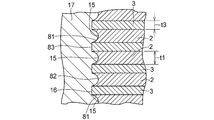
- the inner peripheral surface 82 of the laminate 7 composed of the inner peripheral surfaces 15 and 16 is a concave surface 81 at the position of the inner peripheral surface 15 of the elastic layer 2.
- 3 is a convex surface 83 and supports
- the elastic layer 2 is compressed in the stacking direction V, and the thickness t1 of the elastic layer 2 is less than 2.5 mm.
- the lead plug 17 that is press-fitted and filled in the hollow portion 14 is moved in the horizontal direction H by the elastic layer 2 against the elastic force of the elastic layer 2.
- the elastic layer 2 protrudes and bites into the elastic layer 2, and the inner peripheral surface 15 of the elastic layer 2 is made a concave surface 81 that is larger and recessed in the horizontal direction (shear direction) H.
- the lead plug 17 has an upper shearing of the upper plate 10 from the lead plug 17 in a state where a load W in the stacking direction V (downward force in the stacking direction V) W from the upper structure to be supported is applied to the upper plate 10.
- Reaction force on the key 45 upward force in the stacking direction V
- Fr surface pressure Pr Fr / (area of the upper end surface 51 of the lead plug 17) N / m 2 , where N is Newton, the same applies hereinafter)
- the above-described seismic isolation support device 1 is configured such that the lower flange plate 63 is connected to the lower structure via the anchor bolt inserted into the through hole 68 and the upper flange plate 43 is connected to the upper portion via the anchor bolt inserted into the through hole 48.
- Each of the structures is fixed between the lower structure and the upper structure, receives the load W of the upper structure, and applies the load W in the stacking direction V applied to the upper plate 10 by the stacked body 7 and the lead plug 17. While supporting, the vibration of the upper plate 10 in the horizontal direction H with respect to the lower plate 11 is damped by the plastic deformation of the lead plug 17, while the transmission of the vibration of the lower plate 11 in the horizontal direction H to the upper plate 10 is laminated. 7 is suppressed by shear elastic deformation in the horizontal direction H.
- the rigid layer 3 between the plurality of rubber plates having an annular thickness t 1 2.5 mm to be the elastic layer 2 and the uppermost and lowermost rigid layers 3.
- a laminated body 7 is formed by disposing steel plates and fixing them together by vulcanization adhesion under pressure in a mold, etc., and then comprises a lower shear key 65 and a lower flange plate 63 via bolts 69.
- the lower plate 11 is fixed to the lowermost rigid layer 3, and then lead is pressed into the hollow portion 14 in order to form the lead plug 17 in the hollow portion 14.
- the lead is pressed into the hollow portion 14 with a hydraulic ram or the like so that the lead plug 17 is constrained by the laminate 7 without a gap in the hollow portion 14.
- the upper plate 10 composed of the upper flange plate 43 and the upper shear key 45 is fixed to the uppermost rigid layer 3.
- the rubber sheet that covers the outer peripheral surfaces 4 and 5 of the elastic layer 2 and the rigid layer 3 and becomes the covering layer 6 is formed on the outer peripheral surfaces 4 and 5.
- the covering layer 6 bonded by vulcanization may be formed on the outer peripheral surfaces 4 and 5 of the elastic layer 2 and the rigid layer 3 simultaneously with the brazing and the vulcanization bonding. Further, in such a formation, a part of the inner peripheral side of the rubber plate that becomes the elastic layer 2 flows to cover the inner peripheral surface 16 of the rigid layer 3, and the covering is sufficiently thinner than the thickness 2 mm of the covering layer 6. A layer may be formed.
- the ratio Pr / P0 between the surface pressure Pr and the surface pressure P0 of the manufactured seismic isolation support device 1 is 1.00 or more, in other words, the ratio Pr between the surface pressure Pr and the surface pressure P0.
- the seismic isolation support device 1 In order to manufacture the seismic isolation support device 1 with / P0 of 1.00 or more, it corresponds to the upper flange plate 43 and the upper shear key 45 and from the upper shear key 45 fitted in the recess 41 and the recess 23.
- a load cell pressure sensor
- a load cell pressure sensor
- an electrical signal of the derived lead wire is measured in a state where a load W to be supported is applied, and a surface pressure Pr is detected from the measured electrical signal, and the detected surface pressure Pr and surface pressure P0 are detected. From this, the ratio Pr / P0 is obtained, and the ratio Pr / P0 is If it is 0.000 or more, the load W on the upper plate 10 is released, the upper flange plate 43 is removed, the temporary upper shear key is replaced with the upper shear key 45, and the upper flange plate 43 is moved to the uppermost position again. When it is fixed to the upper rigid layer 3 with bolts 49 and the ratio Pr / P0 is smaller than 1.00, the load W to be supported by the seismic isolation support device 1 on the upper plate 10 is loaded.
- the upper flange plate 43 and the temporary upper shear key are removed, and additional lead is press-fitted into the hollow portion 14.
- the press-fitting of the additional lead into the hollow portion 14 is performed by pushing the additional lead into the upper portion of the hollow portion 14 with a hydraulic ram or the like.
- the upper flange plate 43 and the temporary upper shear key, and the load cell (pressure sensor) between the upper flange plate 43 and the temporary upper shear key are placed on the uppermost rigid layer 3.
- the ratio Pr / P0 is obtained from the surface pressure Pr based on the electrical signal from the load cell and the surface pressure P0.
- the ratio Pr / P0 is equal to or greater than 1.00.
- the upper shear key 45 and the upper flange plate 43 are fixed to the uppermost rigid layer 3 with bolts 49, while the ratio Pr / P0 is smaller than 1.00. Until the ratio Pr / P0 becomes 1.00 or more, the press-fitting of the additional lead into the hollow portion 14 is repeated.
- the lead plug 17 disposed in the hollow portion 14 is provided without a predetermined gap.
- the elastic layer 2 and the rigid layer 3 and the upper plate 10 and the lower plate 11 stable seismic isolation characteristics can be obtained, and in addition, fatigue and damage of the elastic layer 2 and the lead plug 17 can be avoided. In particular, excellent durability, seismic isolation effect and manufacturability can be obtained.
Landscapes
- Engineering & Computer Science (AREA)
- General Engineering & Computer Science (AREA)
- Mechanical Engineering (AREA)
- Physics & Mathematics (AREA)
- Acoustics & Sound (AREA)
- Aviation & Aerospace Engineering (AREA)
- Architecture (AREA)
- Vibration Prevention Devices (AREA)
- Buildings Adapted To Withstand Abnormal External Influences (AREA)
- Springs (AREA)
Abstract
免震支持装置1は、交互に積層された弾性層2及び剛性層3を有する積層体7と、積層体7の積層方向Vの円環状の上端面8及び下端面9に取付けられた上板10及び下板11と、弾性層2及び剛性層3並びに上板10及び下板11で取り囲まれていると共に上板10の下面12から下板11の上面13まで積層方向Vに伸びた中空部14に配された鉛プラグ17とを具備している。
Description
本発明は、二つの構造物間に配されて両構造物間の相対的な水平振動のエネルギを吸収し、構造物への振動加速度を低減するための装置、特に地震エネルギを減衰して地震入力加速度を低減し、建築物、橋梁等の構造物の損壊を防止する免震支持装置に関する。
交互に積層された弾性層及び剛性層並びにこれら弾性層及び剛性層の内周面で規定された中空部を有する積層体と、この積層体の中空部に配された鉛プラグとを具備した免震支持装置は、知られている。
斯かる免震支持装置は、構造物の鉛直荷重を積層体及び鉛プラグで支持すると共に地震に起因する積層体の積層方向の一端に対しての構造物の水平方向の振動を鉛プラグの塑性変形(剪断変形)で減衰させる一方、同じく地震に起因する積層体の積層方向の一端の水平方向の振動の構造物への伝達を積層体の弾性変形(剪断変形)で抑制するようになっている。
ところで、この種の免震支持装置では、鉛プラグを得るべく積層体の中空部に鉛が圧入、充填されるが、圧入、充填されて積層体の剛性層及び弾性層の内周面に取り囲まれた鉛プラグは、弾性層の弾性により部分的に押し戻されることになるが、この押し戻により鉛プラグには内圧が発生する。
この発生した鉛プラグの内圧が弾性層の剛性との関連で充分でないと、免震支持装置の免震動作において、鉛プラグの外周面と剛性層及び弾性層の内周面との間に隙間が生じて、鉛プラグで効果的に振動を減衰させることができなくなる虞が生じる。
斯かる問題は、鉛プラグにおいて顕著に生じるのであるが、斯かる鉛プラグに限らず、塑性変形で振動エネルギを吸収する鉛、錫又は非鉛系低融点合金等の減衰材料からなる振動減衰体でも生じ得る。
本発明は、前記諸点に鑑みてなされたものであって、積層体の中空部に配された振動減衰体を所定に隙間なしに拘束し得る結果、安定な免震特性を得ることができ、加えて積層体の弾性層及び振動減衰体の疲労、損壊を回避することができ、耐久性及び免震効果並びに製造性に特に優れた免震支持装置を提供することを目的とする。
本発明による免震支持装置は、交互に積層された弾性層及び剛性層を有する積層体と、積層体の上端面及び下端面に取付けられた上板及び下板と、弾性層及び剛性層並びに上板及び下板で取り囲まれていると共に上板の下面から下板の上面まで積層方向に伸びた中空部に配された振動減衰体とを具備していると共に上板に加わる積層方向の荷重を積層体及び振動減衰体で支持するようになっており、支持する積層方向の荷重に基づく振動減衰体からの上板への面圧Prと当該荷重に基づく積層体の荷重に対する受圧面での面圧P0との比Pr/P0が1.00以上(比Pr/P0≧1.00)となるように、振動減衰体が中空部に配されてなる。
本発明による免震支持装置は、また、交互に積層された弾性層及び剛性層を有する積層体と、積層体の上端面及び下端面に取付けられた上板及び下板と、弾性層及び剛性層並びに上板及び下板で取り囲まれていると共に上板の下面から下板の上面まで積層方向に伸びた中空部に当該弾性層及び剛性層並びに上板及び下板に対して隙間なしに配された振動減衰体とを具備していると共に上板に加わる積層方向の荷重を積層体及び振動減衰体で支持するようになっており、支持する積層方向の荷重に基づく振動減衰体からの上板への面圧Prと当該荷重に基づく積層体の荷重に対する受圧面での面圧P0との比Pr/P0が1.00以上(比Pr/P0≧1.00)となるように、振動減衰体が中空部に配されてなる。
本発明による免震支持装置は、更にまた、交互に積層された弾性層及び剛性層を有する積層体と、積層体の上端面及び下端面に取付けられた上板及び下板と、弾性層及び剛性層並びに上板及び下板で取り囲まれていると共に上板の下面から下板の上面まで積層方向に伸びた中空部に配された振動減衰体とを具備していると共に上板に加わる積層方向の荷重を積層体及び振動減衰体で支持すると共に下板に対しての上板の積層方向に直交する方向の振動を振動減衰体の塑性変形で減衰させる一方、下板の積層方向に直交する方向の振動の上板への伝達を積層体の剪断弾性変形で抑制するようになっており、支持する積層方向の荷重に基づく振動減衰体からの上板への面圧Prと当該荷重に基づく積層体の荷重に対する受圧面での面圧P0との比Pr/P0が1.00以上(比Pr/P0≧1.00)となるように、振動減衰体が中空部に配されてなる。
加えて、本発明による免震支持装置は、交互に積層された弾性層及び剛性層を有する積層体と、積層体の上端面及び下端面に取付けられた上板及び下板と、弾性層及び剛性層並びに上板及び下板で取り囲まれていると共に上板の下面から下板の上面まで積層方向に伸びた中空部に当該弾性層及び剛性層並びに上板及び下板に対して隙間なしに配された振動減衰体とを具備していると共に上板に加わる積層方向の荷重を積層体及び振動減衰体で支持すると共に下板に対しての上板の積層方向に直交する方向の振動を振動減衰体の塑性変形で減衰させる一方、下板の積層方向に直交する方向の振動の上板への伝達を積層体の剪断弾性変形で抑制するようになっており、支持する積層方向の荷重に基づく振動減衰体からの上板への面圧Prと当該荷重に基づく積層体の荷重に対する受圧面での面圧P0との比Pr/P0が1.00以上(比Pr/P0≧1.00)となるように、振動減衰体が中空部に配されてなる。
本発明は、支持する構造物から上板に加えられた荷重(鉛直荷重)Wで弾性層が積層方向(鉛直方向)において圧縮されて中空部の高さ(積層方向の長さ)が低くなると、振動減衰体が弾性層の内周面を押圧して部分的に弾性層に積層方向に直交する方向(水平方向、即ち、剪断方向)に張り出し、この張り出し、言い換えると、振動減衰体による弾性層の内周面への押圧に起因する弾性層の弾性反力に基づく振動減衰体に生じる内圧であって振動減衰体からの上板への面圧Prと当該荷重に基づく積層体の荷重に対する受圧面での面圧P0との比Pr/P0が一定の関係となるように、振動減衰体が中空部に配されてなる免震支持装置では、中空部に配された振動減衰体を所定に隙間なしに拘束し得るという知見に基づいてなされたものである。
斯かる知見に基づく本発明の免震支持装置では、面圧Prと面圧P0との比Pr/P0が1.00以上(比Pr/P0≧1.00)、好ましくは、1.00を超える(比Pr/P0>1.00)ように、より好ましくは、1.09以上(比Pr/P0≧1.09)、更により好ましくは、2.02以上(比Pr/P0≧2.02)、最も好ましくは、2.50以上(比Pr/P0≧2.50)となるように、振動減衰体が中空部に好ましくは密に配されていると、積層方向に直交する方向の積層体の剪断弾性変形においても、中空部に配された振動減衰体を所定に隙間なしに弾性層及び剛性層並びに上板及び下板で拘束し得る結果、安定な免震特性を得ることができ、加えて弾性層及び振動減衰体の疲労、損壊を回避することができ、耐久性及び免震効果並びに製造性に特に優れた免震支持装置を提供することができる。
本発明において、振動減衰体からの上板への面圧Prは、構造物からの荷重の大きさと中空部への振動減衰体の充填の程度と弾性層の弾性率又は剛性率の高低とによって増減し、比Pr/P0が1.00以上である免震支持装置では、中空部を規定する積層体の内周面は、振動減衰体が弾性層に適切に食い込んで、当該弾性層の位置では環状の凹面になり、剛性層の位置では環状の凸面になる。
ところで、比Pr/P0が1.00よりも小さい免震支持装置では、中空部を規定する弾性層及び剛性層並びに上板及び下板と、これらに接する振動減衰体の外周面との間に隙間が生じ易くなり、したがって免震支持装置の作動中に、容易に弾性層及び剛性層並びに上板及び下板と振動減衰体の外周面との間に隙間が生じ、不安定な免震特性を示すことになる。これは、振動減衰体が積層体に少なくとも剪断方向(水平方向)において隙間なく拘束されず、振動減衰体に剪断変形以外の変形を生じることによるものと推測される。
一方、比Pr/P0が一定以上大きい免震支持装置、具体的には、比Pr/P0が5.90よりも大きい免震支持装置では、振動減衰体が大きく弾性層に食い込んで、弾性層の内周面が過度に凹面になり、この部位の近傍での弾性層と剛性層との間の剪断応力が大きくなり過ぎ、弾性層の劣化を早め、弾性層の耐久性が劣ることになり、また、比Pr/P0が斯かる5.90よりも大きい免震支持装置を得るには、振動減衰体の中空部への圧入を極めて大きくしなければならず、免震支持装置の製造が困難であることも判った。
そして、中空部に配された振動減衰体を所定に隙間なしに弾性層及び剛性層並びに上板及び下板で拘束し得て、安定な免震特性を得ることができ、加えて弾性層及び振動減衰体の疲労、損壊を回避することができ、耐久性及び免震効果並びに製造性に特に優れた免震支持装置を得ることのできる比Pr/P0は、本発明の免震支持装置で免震支持する建築物及び橋梁での各荷重Wで好ましい範囲が存在するが、該各免震支持装置は、比Pr/P0≧1.00であって、比Pr/P0≦5.90であると、小さな振動入力では、高い剛性を示し、大きな振動入力では、低い剛性を示す機能、いわゆるトリガ機能を得ることができる上に、大振幅の地震動に特に好ましく対応し得、しかも、製造性に極めて優れる。
本発明において、振動減衰体は、好ましい例では、塑性変形で振動エネルギを吸収する減衰材料からなり、斯かる減衰材料は、鉛、錫又は非鉛系低融点合金(例えば、錫-亜鉛系合金、錫-ビスマス系合金及び錫-インジウム系合金より選ばれる錫含有合金であって、具体的には、錫42~43重量%及びビスマス57~58重量%を含む錫-ビスマス合金等)からなっていてもよい。
本発明において、上板及び積層方向において最上位の剛性層に関して、好ましい例では、上板は、上部貫通孔を有した上部フランジ板と、この上部貫通孔において上部フランジ板に固着された上部閉塞板とを具備しており、振動減衰体の積層方向の上端面は、上部閉塞板の積層方向の下端面に隙間なしに接触しており、振動減衰体の積層方向の上端部の外周面は、上部貫通孔を規定する上部フランジ板の内周面に隙間なしに接触しており、他の好ましい例では、積層方向において最上位の剛性層は、その上面で開口していると共に積層方向における中空部の上部の径よりも大きな径をもって当該中空部の上部に連通した第一の凹所を有しており、上板は、その下面で開口していると共に第一の凹所の径と同一の径をもって積層方向において第一の凹所に対面した第二の凹所を有した上部フランジ板と、この第二の凹所において上部フランジ板に嵌着されている一方、第一の凹所において最上位の剛性層に嵌着されている上部剪断キーとを具備しており、振動減衰体の積層方向の上端部の外周面は、中空部の上部を規定する最上位の剛性層の内周面に隙間なしに接触している。
本発明において、下板及び積層方向において最下位の剛性層に関して、好ましい例では、下板は、下部貫通孔を有した下部フランジ板と、この下部貫通孔において下部フランジ板に固着された下部閉塞板とを具備しており、振動減衰体の積層方向の下端面は、下部閉塞板の積層方向の上端面に隙間なしに接触しており、振動減衰体の積層方向の下端部の外周面は、下部貫通孔を規定する下部フランジ板の内周面に隙間なしに接触しており、他の好ましい例では、積層方向において最下位の剛性層は、その下面で開口していると共に積層方向における中空部の下部の径よりも大きな径をもって当該中空部の下部に連通した第三の凹所を有しており、下板は、その上面で開口していると共に第三の凹所の径と同一の径をもって積層方向において第三の凹所に対面した第四の凹所を有した下部フランジ板と、この第四の凹所において下部フランジ板に嵌着されている一方、第三の凹所において最下位の剛性層に嵌着されている下部剪断キーとを具備しており、振動減衰体の積層方向の下端部の外周面は、中空部の下部を規定する最下位の剛性層の内周面に隙間なしに接触している。
上部フランジ板及び下部フランジ板は、外縁が円形若しくは楕円形であっても、これに代えて、外縁が矩形若しくは方形であってもよい。
本発明では、弾性層の素材としては、天然ゴム、シリコンゴム、高減衰ゴム、ウレタンゴム又はクロロプレンゴム等を挙げることができるが、好ましくは天然ゴムであり、弾性層の各層は、好ましくは、無負荷状態(支持する積層方向の荷重が上板に加えられていない状態)において1mm~30mm程度の厚みを有しているが、これに限定されず、また、剛性層の素材としては、鋼板、炭素繊維、ガラス繊維若しくはアラミド繊維等の繊維補強合成樹脂板又は繊維補強硬質ゴム板等を挙げることができ、剛性層の各層は、1mm~6mm程度の厚みを有していても、また、最上位及び最下位の剛性層は、10mm~50mm程度の厚みを有していてもよいが、これらに限定されず、加えて、弾性層及び剛性層は、その枚数においても特に限定されず、支持する構造物の荷重、剪断変形量(水平方向歪量)、弾性層の弾性率、予測される構造物への振動加速度の大きさの観点から、安定な免震特性を得るべく、弾性層及び剛性層の枚数を決定すればよい。
また、本発明では、弾性体及び振動減衰体は、円環状体及び円柱状体が好ましいが、他の形状のもの、例えば楕円若しくは方形体及び楕円若しくは方形体のものであってもよく、中空部は、一つでもよいが、これに代えて、免震支持装置は、複数の中空部を有していてもよく、この複数の中空部にそれぞれ振動減衰体を配して免震支持装置を構成してもよい。なお、これら複数の中空部の夫々に関して、比Pr/P0が同一である必要はなく、比Pr/P0がそれぞれ異なっていてもよく、また、これら複数の中空部の夫々に関して比Pr/P0が上記の通り、1.00以上であることが好ましいが、複数の中空部の一部に関してのみ比Pr/P0が1.00以上であってもよい。
本発明によれば、積層体の中空部に配された振動減衰体を所定に隙間なしに拘束し得る結果、安定な免震特性を得ることができ、加えて積層体の弾性層及び振動減衰体の疲労、損壊を回避することができ、耐久性及び免震効果並びに製造性に特に優れた免震支持装置を提供することができる。
以下、本発明及びその実施の形態を、図に示す好ましい具体例に基づいて説明する。なお、本発明は本具体例に何等限定されないのである。
図1から図3に示す本例の免震支持装置1は、交互に積層された複数の弾性層2及び剛性層3に加えて、弾性層2及び剛性層3の円筒状の外周面4及び5を被覆した円筒状の被覆層6を有する円筒状の積層体7と、積層体7の積層方向(本例では、鉛直方向でもある)Vの円環状の上端面8及び下端面9に取付けられた上板10及び下板11と、弾性層2及び剛性層3並びに上板10及び下板11で取り囲まれていると共に上板10の下面12から下板11の上面13まで積層方向Vに伸びた中空部14に、当該弾性層2の内周面15及び剛性層3の円筒状の内周面16並びに上板10の下面12及び下板11の上面13に対して隙間なしに配された振動減衰体としての鉛プラグ17とを具備している。
厚さt1=2.5mmの天然ゴム製の円環状のゴム板からなる弾性層2の夫々は、積層方向Vにおいて対面する剛性層3の積層方向Vの上面及び下面に加硫接着されている。
剛性層3において、積層方向Vにおいて最上位及び最下位の剛性層3の夫々は、厚さt2=20mmの円環状の互いに同一の鋼板からなり、最上位の剛性層3は、その上面21で開口していると共に円筒状の内周面22で規定された凹所23と、同じく上面21で開口していると共に円周方向Rにおいて等角度間隔に配された複数個の螺子穴24とを有しており、積層方向Vにおける中空部14の上部25を規定する最上位の剛性層3の内周面16の径よりも大きな径をもった内周面22で規定された凹所23は、当該中空部14の上部25に連通しており、最下位の剛性層3は、その下面26で開口していると共に内周面22と同径の円筒状の内周面27で規定された凹所28と、同じく下面26で開口していると共に円周方向Rにおいて等角度間隔に配された複数個の螺子穴29とを有しており、積層方向Vにおける中空部14の下部30を規定する最下位の剛性層3の内周面16の径よりも大きな径をもった内周面27で規定された凹所28は、当該中空部14の下部30に連通しており、積層方向Vにおいて最上位の剛性層3と最下位の剛性層3と間に配された剛性層3の夫々は、最上位及び最下位の剛性層3よりも薄い厚さt3=1.6mmの円環状の互いに同一の鋼板からなる。
厚さ5mm程度であって弾性層2と同一の天然ゴムからなると共に円筒状の外周面31並びに円環状の上端面32及び下端面33を有した被覆層6は、その円筒状の内周面34で外周面4及び5に加硫接着されている。
上板10は、凹所23の径と同一の径をもって積層方向Vにおいて凹所23に対面した凹所41を下面42に有した円板状の上部フランジ板43と、凹所41において上部フランジ板43に嵌着されている一方、凹所23において最上位の剛性層3に嵌着されていると共に円形の下面44を有した上部剪断キー45とを具備しており、円筒状の外周面46を有した上部フランジ板43は、凹所41に加えて、積層方向Vにおいて複数個の螺子穴24に対応して円周方向Rにおいて等角度間隔に配された複数個の貫通孔47と、外周面46の近傍に円周方向Rにおいて等角度間隔に配された複数個の貫通孔48とを有しており、貫通孔47の夫々に挿入されて螺子穴24の夫々において最上位の剛性層3に螺合されたボルト49を介して最上位の剛性層3に固定される一方、支持する上部の構造物に貫通孔48に挿入されるアンカーボルトを介して固定されるようになっている。
而して、上部フランジ板43と上部剪断キー45とを具備した上板10の下面12は、下面42と下面44とからなり、上面21と上端面32とからなる上端面8は、下面12における下面42に隙間なしに接触しており、鉛プラグ17は、その円形の上端面51で下面12における下面44に隙間なしに接触しており、上部25に配された鉛プラグ17の積層方向Vの上端部52の外周面53は、最上位の剛性層3の内周面16に隙間なしに接触している。
下板11は、凹所28の径と同一の径をもって積層方向Vにおいて凹所28に対面した凹所61を上面62に有した円板状の下部フランジ板63と、凹所61において下部フランジ板63に嵌着されている一方、凹所28において最下位の剛性層3に嵌着されていると共に円形の上面64を有した下部剪断キー65とを具備しており、円筒状の外周面66を有した下部フランジ板63は、凹所61に加えて、積層方向Vにおいて複数個の螺子穴29に対応して円周方向Rにおいて等角度間隔に配された複数個の貫通孔67と、外周面66の近傍に円周方向Rにおいて等角度間隔に配された複数個の貫通孔68とを有しており、貫通孔67の夫々に挿入されて螺子穴29の夫々において最下位の剛性層3に螺合されたボルト69を介して最下位の剛性層3に固定される一方、載置される下部の構造物に貫通孔68に挿入されるアンカーボルトを介して固定されるようになっている。
而して、下部フランジ板63と下部剪断キー65とを具備した下板11の上面13は、
上面62と上面64とからなり、下面26と下端面33とからなる下端面8は、上面13における上面62に隙間なしに接触しており、鉛プラグ17は、その円形の下端面71で上面13における上面64に隙間なしに接触しており、下部30に配された鉛プラグ17の積層方向Vの下端部72の外周面73は、最下位の剛性層3の内周面16に隙間なしに接触している。
上面62と上面64とからなり、下面26と下端面33とからなる下端面8は、上面13における上面62に隙間なしに接触しており、鉛プラグ17は、その円形の下端面71で上面13における上面64に隙間なしに接触しており、下部30に配された鉛プラグ17の積層方向Vの下端部72の外周面73は、最下位の剛性層3の内周面16に隙間なしに接触している。
塑性変形で振動エネルギを吸収する減衰材料である鉛からなる鉛プラグ17は、下面44、内周面15及び16並びに上面64によって規定された中空部14に圧入、充填されており、斯かる圧入、充填で鉛プラグ17は、支持する上部の構造物からの積層方向Vの荷重Wが上板10に加えられていない状態(無荷重下)でも、当該下面44、外周面4及び5並びに上面64に対して隙間なしに配されていると共に弾性層2の弾性力に抗して弾性層2に向って水平方向(剪断方向)Hに張り出して弾性層2に若干食い込み、弾性層2の内周面15を凹面81にする結果、内周面15及び16からなる積層体7の内周面82は、当該弾性層2の内周面15の位置で凹面81になっている一方、剛性層3の位置で凸面83になっており、支持する上部の構造物からの積層方向Vの荷重Wが上板10に加えられた状態(荷重下)では、弾性層2が積層方向Vにおいて圧縮されて弾性層2の厚みt1が2.5mmよりも小さくなって免震支持装置1の高さhが低くなる結果、中空部14に圧入、充填された鉛プラグ17は、弾性層2の弾性力に抗して当該弾性層2により水平方向Hに張り出して弾性層2に食い込み、弾性層2の内周面15をより大きく水平方向(剪断方向)Hに凹んだ凹面81にする。
鉛プラグ17は、支持する上部の構造物からの積層方向Vの荷重(積層方向Vの下向きの力)Wが上板10に加えられた状態での鉛プラグ17からの上板10の上部剪断キー45への反力(積層方向Vの上向きの力)Frによる面圧Pr(=Fr/(鉛プラグ17の上端面51の面積)N/m2、但しNはニュートン、以下、同じ)と当該荷重Wによる積層体7の受圧面での面圧P0(=W/(積層体7の荷重Wに対する受圧面積)N/m2)との比Pr/P0が1.00以上になるように、中空部14に密に配されている。
以上の免震支持装置1は、下部フランジ板63が貫通孔68に挿入されたアンカーボルトを介して下部の構造物に、上部フランジ板43が貫通孔48に挿入されたアンカーボルトを介して上部の構造物に夫々固定されて下部及び上部の構造物間に配され、上部の構造物の荷重Wを受けて、上板10に加わる積層方向Vの荷重Wを積層体7及び鉛プラグ17で支持すると共に下板11に対しての上板10の水平方向Hの振動を鉛プラグ17の塑性変形で減衰させる一方、下板11の水平方向Hの振動の上板10への伝達を積層体7の水平方向Hの剪断弾性変形で抑制するようになっている。
免震支持装置1を製造する場合には、まず、弾性層2となる円環状の厚さt1=2.5mmの複数枚のゴム板と最上位及び最下位の剛性層3間の剛性層3となる円環状の厚さt3=1.6mmの複数枚の鋼板とを交互に積層して、その下面及び上面に最上位及び最下位の剛性層3となる円環状の厚さt2=20mmの鋼板を配置し、型内における加圧下での加硫接着等によりこれらを相互に固定してなる積層体7を形成し、その後、ボルト69を介して下部剪断キー65及び下部フランジ板63からなる下板11を最下位の剛性層3に固定し、次に、鉛プラグ17を中空部14に形成すべく、中空部14に鉛を圧入する。鉛の圧入は、鉛プラグ17が積層体7により中空部14において隙間なしに拘束されるように、鉛を中空部14に油圧ラム等により押し込んで行い、鉛の圧入後、ボルト49を介して上部フランジ板43と上部剪断キー45とからなる上板10を最上位の剛性層3に固定する。なお、型内における加圧下での加硫接着による積層体7の形成において、弾性層2及び剛性層3の外周面4及び5を覆って被覆層6となるゴムシートを外周面4及び5に捲き付け、該加硫接着と同時に、弾性層2及び剛性層3の外周面4及び5に加硫接着された被覆層6を形成してもよい。また斯かる形成において、弾性層2となるゴム板の内周側の一部が流動して、剛性層3の内周面16を覆って、被覆層6の厚さ2mmよりも充分に薄い被覆層が形成されてもよい。
製造された免震支持装置1が面圧Prと面圧P0との比Pr/P0が1.00以上であることを確認するために、言い換えると、面圧Prと面圧P0との比Pr/P0が1.00以上である免震支持装置1を製造するために、上部フランジ板43と上部剪断キー45に相当すると共に凹所41及び凹所23に嵌着された上部剪断キー45よりも薄い仮の上部剪断キーとの間にロードセル(圧力センサ)を介在させ、ロードセルからのリード線を上部フランジ板43に形成された細孔から導出して、上板10に本免震支持装置1で支持する予定の荷重Wを加えた状態でこの導出されたリード線の電気信号を測定して、この測定した電気信号から面圧Prを検出し、この検出した面圧Prと面圧P0とから比Pr/P0を求め、比Pr/P0が1.00以上である場合には、上板10への荷重Wの負荷を解除して上部フランジ板43を取り外し、仮の上部剪断キーを上部剪断キー45に取り換え、再び、上部フランジ板43を最上位の剛性層3にボルト49を介して固定し、比Pr/P0が1.00よりも小さい場合には、上板10への本免震支持装置1で支持する予定の荷重Wの負荷を解除して上部フランジ板43及び仮の上部剪断キーを取り外し、中空部14に追加の鉛を圧入する。追加の鉛の中空部14への圧入は、追加の鉛を中空部14の上部に油圧ラム等により押し込んで行う。追加の鉛の中空部14への圧入後、上部フランジ板43と仮の上部剪断キーと、上部フランジ板43及び仮の上部剪断キー間のロードセル(圧力センサ)とを最上位の剛性層3にボルト49を介して固定し、ロードセルからの電気信号に基づく面圧Prと面圧P0とから比Pr/P0を求め、比Pr/P0が1.00以上である場合には、上記と同様にして仮の上部剪断キーに代えて上部剪断キー45と上部フランジ板43とを最上位の剛性層3にボルト49を介して固定する一方、比Pr/P0が1.00よりも小さい場合には、比Pr/P0が1.00以上になるまで、以上の追加の鉛の中空部14への圧入を繰り返す。
なお、比Pr/P0が1.00以上になる場合には、無荷重(W=0)で弾性層2の内周面15が凹面81に変形しなくてもよい。
こうして製造された免震支持装置1では、面圧Prと面圧P0との比Pr/P0が1.00以上であるために、中空部14に配された鉛プラグ17を所定に隙間なしに弾性層2及び剛性層3並びに上板10及び下板11で拘束し得る結果、安定な免震特性を得ることができ、加えて弾性層2及び鉛プラグ17の疲労、損壊を回避することができ、特に優れた耐久性及び免震効果並びに製造性を得ることができる。
実施例1から3の免震支持装置1
弾性層2:厚さt1=2.5mm、外周面4の径(外径)=250mm、変形前の円筒状の内周面15の径(内径)=50mmであって、せん断弾性率=G4の天然ゴムからなる円環状のゴム板を20枚使用
最上位及び最下位の剛性層3:夫々厚さt2=20mm、外周面5の径(外径)=250mm、内周面16の径(内径)=50mmの鋼板を使用
凹所23及び28の夫々の深さ=10mm
最上位及び最下位の剛性層3間の剛性層3:厚さt3=1.6mm、外周面5の径(外径)=250mm、内周面16の径(内径)=50mmの鋼板を19枚使用
被覆層6の厚さ=5mm
免震支持装置1において、支持する荷重W=600kNに対して、実施例1では、比Pr/P0=1.09となるように、実施例2では、比Pr/P0=2.02となるように、そして、実施例3では、比Pr/P0=2.50となるように、中空部14に鉛を充填した。
弾性層2:厚さt1=2.5mm、外周面4の径(外径)=250mm、変形前の円筒状の内周面15の径(内径)=50mmであって、せん断弾性率=G4の天然ゴムからなる円環状のゴム板を20枚使用
最上位及び最下位の剛性層3:夫々厚さt2=20mm、外周面5の径(外径)=250mm、内周面16の径(内径)=50mmの鋼板を使用
凹所23及び28の夫々の深さ=10mm
最上位及び最下位の剛性層3間の剛性層3:厚さt3=1.6mm、外周面5の径(外径)=250mm、内周面16の径(内径)=50mmの鋼板を19枚使用
被覆層6の厚さ=5mm
免震支持装置1において、支持する荷重W=600kNに対して、実施例1では、比Pr/P0=1.09となるように、実施例2では、比Pr/P0=2.02となるように、そして、実施例3では、比Pr/P0=2.50となるように、中空部14に鉛を充填した。
比較例の免震支持装置
支持する荷重W=600kNに対して、比Pr/P0=0.73となるように中空部14に鉛を充填した以外、実施例1から3と同様の免震支持装置を製造した。
支持する荷重W=600kNに対して、比Pr/P0=0.73となるように中空部14に鉛を充填した以外、実施例1から3と同様の免震支持装置を製造した。
実施例1から3の免震支持装置1と比較例の免震支持装置との夫々の上板10に荷重W=600kNを加えた状態で、最大±5mmの水平変位をもって上板10に対して下板11に水平方向Hに振動を加えた場合の水平変位-水平力(水平応力)の履歴特性を測定した結果を図4から図7に示す。図4から図6に示す履歴特性から明らかであるように、実施例1から3の免震支持装置1では、安定な免震特性を得ることができ、トリガ機能を有し、大振幅の地震に対して好ましく対応し得、また、図7に示す履歴特性から明らかであるように、比較例の免震支持装置では、矢印で示すように凹みが生じて不安定な免震特性となり、トリガ機能を好ましく得ることができないことが判る。なお、比Pr/P0が5.90以下であれば、製造において中空部14への鉛の圧入が容易であり、それほど困難を伴わないことが判明した。また、比Pr/P0が5.90を超えるように、中空部14へ鉛を圧入しようとしたが、弾性層2の内周面15の損壊なしに、これを行うことは困難であることも判明した。
図4と図7とに示す履歴特性の比較から明らかであるように、比Pr/P0が1.00となるように、鉛プラグ17が中空部14に配されていると、図4に示す履歴特性と同等の履歴特性が得られることも確認した。
1 免震支持装置
2 弾性層
3 剛性層
4、5 外周面
6 被覆層
7 積層体
8 上端面
9 下端面
10 上板
11 下板
12 下面
13 上面
14 中空部
15 内周面
16 内周面
17 鉛プラグ
2 弾性層
3 剛性層
4、5 外周面
6 被覆層
7 積層体
8 上端面
9 下端面
10 上板
11 下板
12 下面
13 上面
14 中空部
15 内周面
16 内周面
17 鉛プラグ
Claims (12)
- 交互に積層された弾性層及び剛性層を有する積層体と、積層体の上端面及び下端面に取付けられた上板及び下板と、弾性層及び剛性層並びに上板及び下板で取り囲まれていると共に上板の下面から下板の上面まで積層方向に伸びた中空部に配された振動減衰体とを具備していると共に上板に加わる積層方向の荷重を積層体及び振動減衰体で支持するようになっている免震支持装置であって、支持する積層方向の荷重に基づく振動減衰体からの上板への面圧Prと当該荷重に基づく積層体の荷重に対する受圧面での面圧P0との比Pr/P0が1.00以上(比Pr/P0≧1.00)となるように、振動減衰体が中空部に配されてなる免震支持装置。
- 交互に積層された弾性層及び剛性層を有する積層体と、積層体の上端面及び下端面に取付けられた上板及び下板と、弾性層及び剛性層並びに上板及び下板で取り囲まれていると共に上板の下面から下板の上面まで積層方向に伸びた中空部に当該弾性層及び剛性層並びに上板及び下板に対して隙間なしに配された振動減衰体とを具備していると共に上板に加わる積層方向の荷重を積層体及び振動減衰体で支持するようになっている免震支持装置であって、支持する積層方向の荷重に基づく振動減衰体からの上板への面圧Prと当該荷重に基づく積層体の荷重に対する受圧面での面圧P0との比Pr/P0が1.00以上(比Pr/P0≧1.00)となるように、振動減衰体が中空部に配されてなる免震支持装置。
- 交互に積層された弾性層及び剛性層を有する積層体と、積層体の上端面及び下端面に取付けられた上板及び下板と、弾性層及び剛性層並びに上板及び下板で取り囲まれていると共に上板の下面から下板の上面まで積層方向に伸びた中空部に配された振動減衰体とを具備していると共に上板に加わる積層方向の荷重を積層体及び振動減衰体で支持すると共に下板に対しての上板の積層方向に直交する方向の振動を振動減衰体の塑性変形で減衰させる一方、下板の積層方向に直交する方向の振動の上板への伝達を積層体の剪断弾性変形で抑制するようになっている免震支持装置であって、支持する積層方向の荷重に基づく振動減衰体からの上板への面圧Prと当該荷重に基づく積層体の荷重に対する受圧面での面圧P0との比Pr/P0が1.00以上(比Pr/P0≧1.00)となるように、振動減衰体が中空部に配されてなる免震支持装置。
- 交互に積層された弾性層及び剛性層を有する積層体と、積層体の上端面及び下端面に取付けられた上板及び下板と、弾性層及び剛性層並びに上板及び下板で取り囲まれていると共に上板の下面から下板の上面まで積層方向に伸びた中空部に当該弾性層及び剛性層並びに上板及び下板に対して隙間なしに配された振動減衰体とを具備していると共に上板に加わる積層方向の荷重を積層体及び振動減衰体で支持すると共に下板に対しての上板の積層方向に直交する方向の振動を振動減衰体の塑性変形で減衰させる一方、下板の積層方向に直交する方向の振動の上板への伝達を積層体の剪断弾性変形で抑制するようになっている免震支持装置であって、支持する積層方向の荷重に基づく振動減衰体からの上板への面圧Prと当該荷重に基づく積層体の荷重に対する受圧面での面圧P0との比Pr/P0が1.00以上(比Pr/P0≧1.00)となるように、振動減衰体が中空部に配されてなる免震支持装置。
- 比Pr/P0が、1.00を超える(比Pr/P0>1.00)ように又は1.09以上(比Pr/P0≧1.09)、2.02以上(比Pr/P0≧2.02)若しくは2.50以上(比Pr/P0≧2.50)となるように、振動減衰体が中空部に配されてなる請求項1から4のいずれか一項に記載の免震支持装置。
- 比Pr/P0が、5.90以下(比Pr/P0≦5.90)となるように、振動減衰体が中空部に配されてなる請求項1から5のいずれか一項に記載の免震支持装置。
- 振動減衰体は、塑性変形で振動エネルギを吸収する減衰材料からなる請求項1から6のいずれか一項に記載の免震支持装置。
- 減衰材料は、鉛、錫又は非鉛系低融点合金からなる請求項7に記載の免震支持装置。
- 中空部を規定する積層体の内周面は、振動減衰体が弾性層に食い込んで、当該弾性層の位置で凹面になっている請求項1から8のいずれか一項に記載の免震支持装置。
- 中空部を規定する積層体の内周面は、振動減衰体が弾性層に食い込んで、剛性層の位置で凸面になっている請求項1から9のいずれか一項に記載の免震支持装置。
- 積層方向において最上位の剛性層は、その上面で開口していると共に中空部の上部の径よりも大きな径をもって当該中空部の上部に連通した第一の凹所を有しており、上板は、第一の凹所の径と同一の径をもって積層方向において第一の凹所に対面した第二の凹所を下面に有した上部フランジ板と、この第二の凹所において上部フランジ板に嵌着されている一方、第一の凹所において最上位の剛性層に嵌着されている上部剪断キーとを具備しており、振動減衰体の上端部の外周面は、中空部の上部を規定する最上位の剛性層の内周面に隙間なしに接触している請求項1から10のいずれか一項に記載の免震支持装置。
- 積層方向において最下位の剛性層は、その下面で開口していると共に中空部の下部の径よりも大きな径をもって当該中空部の下部に連通した第三の凹所を有しており、下板は、第三の凹所の径と同一の径をもって積層方向において第三の凹所に対面した第四の凹所を上面に有した下部フランジ板と、この第四の凹所において下部フランジ板に嵌着されている一方、第三の凹所において最下位の剛性層に嵌着されている下部剪断キーとを具備しており、振動減衰体の下端部の外周面は、中空部の下部を規定する最下位の剛性層の内周面に隙間なしに接触している請求項1から11のいずれか一項に記載の免震支持装置。
Applications Claiming Priority (2)
| Application Number | Priority Date | Filing Date | Title |
|---|---|---|---|
| JP2016-142870 | 2016-07-20 | ||
| JP2016142870A JP2018013172A (ja) | 2016-07-20 | 2016-07-20 | 免震支持装置 |
Publications (1)
| Publication Number | Publication Date |
|---|---|
| WO2018016402A1 true WO2018016402A1 (ja) | 2018-01-25 |
Family
ID=60992999
Family Applications (1)
| Application Number | Title | Priority Date | Filing Date |
|---|---|---|---|
| PCT/JP2017/025433 Ceased WO2018016402A1 (ja) | 2016-07-20 | 2017-07-12 | 免震支持装置 |
Country Status (3)
| Country | Link |
|---|---|
| JP (1) | JP2018013172A (ja) |
| TW (1) | TW201805508A (ja) |
| WO (1) | WO2018016402A1 (ja) |
Families Citing this family (1)
| Publication number | Priority date | Publication date | Assignee | Title |
|---|---|---|---|---|
| CN110983959B (zh) * | 2019-11-21 | 2021-08-10 | 洛阳双瑞特种装备有限公司 | 一种隔震橡胶支座 |
Citations (5)
| Publication number | Priority date | Publication date | Assignee | Title |
|---|---|---|---|---|
| JP2001074096A (ja) * | 1999-09-07 | 2001-03-23 | Fujita Corp | 免震用積層ゴム装置の製造方法 |
| JP2006170233A (ja) * | 2004-12-13 | 2006-06-29 | Showa Electric Wire & Cable Co Ltd | 免震アイソレータと免震構造体 |
| JP2006242240A (ja) * | 2005-03-02 | 2006-09-14 | Sumitomo Metal Mining Co Ltd | エネルギー吸収装置 |
| JP2008292000A (ja) * | 1995-08-04 | 2008-12-04 | Oiles Ind Co Ltd | 免震装置 |
| JP2015007468A (ja) * | 2013-05-30 | 2015-01-15 | オイレス工業株式会社 | 減衰材料及びその減衰材料を用いた振動減衰部材並びにその振動減衰部材を組み込んだ免震装置 |
Family Cites Families (3)
| Publication number | Priority date | Publication date | Assignee | Title |
|---|---|---|---|---|
| NZ245378A (en) * | 1992-12-04 | 1997-04-24 | Damping Systems Ltd Substitute | Bearing with plastically deformable core and surround which hydrostatically pressures the material of the core at or beyond its shear yield stress and methods of making |
| JP3024562B2 (ja) * | 1995-08-04 | 2000-03-21 | オイレス工業株式会社 | 免震装置 |
| JPH11159573A (ja) * | 1997-12-01 | 1999-06-15 | Sumitomo Rubber Ind Ltd | 積層ゴム支承体の製造方法 |
-
2016
- 2016-07-20 JP JP2016142870A patent/JP2018013172A/ja active Pending
-
2017
- 2017-07-12 WO PCT/JP2017/025433 patent/WO2018016402A1/ja not_active Ceased
- 2017-07-17 TW TW106123771A patent/TW201805508A/zh unknown
Patent Citations (5)
| Publication number | Priority date | Publication date | Assignee | Title |
|---|---|---|---|---|
| JP2008292000A (ja) * | 1995-08-04 | 2008-12-04 | Oiles Ind Co Ltd | 免震装置 |
| JP2001074096A (ja) * | 1999-09-07 | 2001-03-23 | Fujita Corp | 免震用積層ゴム装置の製造方法 |
| JP2006170233A (ja) * | 2004-12-13 | 2006-06-29 | Showa Electric Wire & Cable Co Ltd | 免震アイソレータと免震構造体 |
| JP2006242240A (ja) * | 2005-03-02 | 2006-09-14 | Sumitomo Metal Mining Co Ltd | エネルギー吸収装置 |
| JP2015007468A (ja) * | 2013-05-30 | 2015-01-15 | オイレス工業株式会社 | 減衰材料及びその減衰材料を用いた振動減衰部材並びにその振動減衰部材を組み込んだ免震装置 |
Also Published As
| Publication number | Publication date |
|---|---|
| JP2018013172A (ja) | 2018-01-25 |
| TW201805508A (zh) | 2018-02-16 |
Similar Documents
| Publication | Publication Date | Title |
|---|---|---|
| WO2017183542A1 (ja) | 免震装置 | |
| JP6613930B2 (ja) | 免震装置 | |
| JP3205393U (ja) | 免震装置 | |
| WO2018194109A1 (ja) | 免震支持装置 | |
| JP6579026B2 (ja) | 橋梁用の免震支承及びそれを用いた橋梁 | |
| WO2018016402A1 (ja) | 免震支持装置 | |
| JP2019127994A (ja) | 免震支持装置 | |
| WO2018194107A1 (ja) | 免震支持装置 | |
| JP4061818B2 (ja) | 免震装置 | |
| JP5845130B2 (ja) | 積層ゴム支承体 | |
| JP2019127996A (ja) | 免震支持装置 | |
| JP7427578B2 (ja) | 免震装置 | |
| JP2019127999A (ja) | 免震支持装置 | |
| JP2019127998A (ja) | 免震支持装置 | |
| JP2023181816A (ja) | 免震装置 | |
| JP6354303B2 (ja) | 積層ゴム支承装置 | |
| JP5524683B2 (ja) | ゴム支承体 | |
| JP2006226414A (ja) | ハードニング特性を有する積層ゴム支承 | |
| JPH05295926A (ja) | 軽量建造物用免震装置 |
Legal Events
| Date | Code | Title | Description |
|---|---|---|---|
| 121 | Ep: the epo has been informed by wipo that ep was designated in this application |
Ref document number: 17830921 Country of ref document: EP Kind code of ref document: A1 |
|
| NENP | Non-entry into the national phase |
Ref country code: DE |
|
| 122 | Ep: pct application non-entry in european phase |
Ref document number: 17830921 Country of ref document: EP Kind code of ref document: A1 |