WO2018016375A1 - ガス供給装置及びガス供給方法 - Google Patents
ガス供給装置及びガス供給方法 Download PDFInfo
- Publication number
- WO2018016375A1 WO2018016375A1 PCT/JP2017/025214 JP2017025214W WO2018016375A1 WO 2018016375 A1 WO2018016375 A1 WO 2018016375A1 JP 2017025214 W JP2017025214 W JP 2017025214W WO 2018016375 A1 WO2018016375 A1 WO 2018016375A1
- Authority
- WO
- WIPO (PCT)
- Prior art keywords
- gas
- compound
- temperature
- storage container
- liquid
- Prior art date
Links
Images


Classifications
-
- F—MECHANICAL ENGINEERING; LIGHTING; HEATING; WEAPONS; BLASTING
- F17—STORING OR DISTRIBUTING GASES OR LIQUIDS
- F17C—VESSELS FOR CONTAINING OR STORING COMPRESSED, LIQUEFIED OR SOLIDIFIED GASES; FIXED-CAPACITY GAS-HOLDERS; FILLING VESSELS WITH, OR DISCHARGING FROM VESSELS, COMPRESSED, LIQUEFIED, OR SOLIDIFIED GASES
- F17C7/00—Methods or apparatus for discharging liquefied, solidified, or compressed gases from pressure vessels, not covered by another subclass
- F17C7/02—Discharging liquefied gases
- F17C7/04—Discharging liquefied gases with change of state, e.g. vaporisation
-
- C—CHEMISTRY; METALLURGY
- C23—COATING METALLIC MATERIAL; COATING MATERIAL WITH METALLIC MATERIAL; CHEMICAL SURFACE TREATMENT; DIFFUSION TREATMENT OF METALLIC MATERIAL; COATING BY VACUUM EVAPORATION, BY SPUTTERING, BY ION IMPLANTATION OR BY CHEMICAL VAPOUR DEPOSITION, IN GENERAL; INHIBITING CORROSION OF METALLIC MATERIAL OR INCRUSTATION IN GENERAL
- C23C—COATING METALLIC MATERIAL; COATING MATERIAL WITH METALLIC MATERIAL; SURFACE TREATMENT OF METALLIC MATERIAL BY DIFFUSION INTO THE SURFACE, BY CHEMICAL CONVERSION OR SUBSTITUTION; COATING BY VACUUM EVAPORATION, BY SPUTTERING, BY ION IMPLANTATION OR BY CHEMICAL VAPOUR DEPOSITION, IN GENERAL
- C23C16/00—Chemical coating by decomposition of gaseous compounds, without leaving reaction products of surface material in the coating, i.e. chemical vapour deposition [CVD] processes
- C23C16/44—Chemical coating by decomposition of gaseous compounds, without leaving reaction products of surface material in the coating, i.e. chemical vapour deposition [CVD] processes characterised by the method of coating
- C23C16/448—Chemical coating by decomposition of gaseous compounds, without leaving reaction products of surface material in the coating, i.e. chemical vapour deposition [CVD] processes characterised by the method of coating characterised by the method used for generating reactive gas streams, e.g. by evaporation or sublimation of precursor materials
- C23C16/4485—Chemical coating by decomposition of gaseous compounds, without leaving reaction products of surface material in the coating, i.e. chemical vapour deposition [CVD] processes characterised by the method of coating characterised by the method used for generating reactive gas streams, e.g. by evaporation or sublimation of precursor materials by evaporation without using carrier gas in contact with the source material
-
- C—CHEMISTRY; METALLURGY
- C23—COATING METALLIC MATERIAL; COATING MATERIAL WITH METALLIC MATERIAL; CHEMICAL SURFACE TREATMENT; DIFFUSION TREATMENT OF METALLIC MATERIAL; COATING BY VACUUM EVAPORATION, BY SPUTTERING, BY ION IMPLANTATION OR BY CHEMICAL VAPOUR DEPOSITION, IN GENERAL; INHIBITING CORROSION OF METALLIC MATERIAL OR INCRUSTATION IN GENERAL
- C23C—COATING METALLIC MATERIAL; COATING MATERIAL WITH METALLIC MATERIAL; SURFACE TREATMENT OF METALLIC MATERIAL BY DIFFUSION INTO THE SURFACE, BY CHEMICAL CONVERSION OR SUBSTITUTION; COATING BY VACUUM EVAPORATION, BY SPUTTERING, BY ION IMPLANTATION OR BY CHEMICAL VAPOUR DEPOSITION, IN GENERAL
- C23C16/00—Chemical coating by decomposition of gaseous compounds, without leaving reaction products of surface material in the coating, i.e. chemical vapour deposition [CVD] processes
- C23C16/44—Chemical coating by decomposition of gaseous compounds, without leaving reaction products of surface material in the coating, i.e. chemical vapour deposition [CVD] processes characterised by the method of coating
- C23C16/448—Chemical coating by decomposition of gaseous compounds, without leaving reaction products of surface material in the coating, i.e. chemical vapour deposition [CVD] processes characterised by the method of coating characterised by the method used for generating reactive gas streams, e.g. by evaporation or sublimation of precursor materials
-
- F—MECHANICAL ENGINEERING; LIGHTING; HEATING; WEAPONS; BLASTING
- F17—STORING OR DISTRIBUTING GASES OR LIQUIDS
- F17C—VESSELS FOR CONTAINING OR STORING COMPRESSED, LIQUEFIED OR SOLIDIFIED GASES; FIXED-CAPACITY GAS-HOLDERS; FILLING VESSELS WITH, OR DISCHARGING FROM VESSELS, COMPRESSED, LIQUEFIED, OR SOLIDIFIED GASES
- F17C13/00—Details of vessels or of the filling or discharging of vessels
- F17C13/02—Special adaptations of indicating, measuring, or monitoring equipment
- F17C13/025—Special adaptations of indicating, measuring, or monitoring equipment having the pressure as the parameter
-
- F—MECHANICAL ENGINEERING; LIGHTING; HEATING; WEAPONS; BLASTING
- F17—STORING OR DISTRIBUTING GASES OR LIQUIDS
- F17C—VESSELS FOR CONTAINING OR STORING COMPRESSED, LIQUEFIED OR SOLIDIFIED GASES; FIXED-CAPACITY GAS-HOLDERS; FILLING VESSELS WITH, OR DISCHARGING FROM VESSELS, COMPRESSED, LIQUEFIED, OR SOLIDIFIED GASES
- F17C13/00—Details of vessels or of the filling or discharging of vessels
- F17C13/02—Special adaptations of indicating, measuring, or monitoring equipment
- F17C13/026—Special adaptations of indicating, measuring, or monitoring equipment having the temperature as the parameter
-
- F—MECHANICAL ENGINEERING; LIGHTING; HEATING; WEAPONS; BLASTING
- F17—STORING OR DISTRIBUTING GASES OR LIQUIDS
- F17C—VESSELS FOR CONTAINING OR STORING COMPRESSED, LIQUEFIED OR SOLIDIFIED GASES; FIXED-CAPACITY GAS-HOLDERS; FILLING VESSELS WITH, OR DISCHARGING FROM VESSELS, COMPRESSED, LIQUEFIED, OR SOLIDIFIED GASES
- F17C9/00—Methods or apparatus for discharging liquefied or solidified gases from vessels not under pressure
- F17C9/02—Methods or apparatus for discharging liquefied or solidified gases from vessels not under pressure with change of state, e.g. vaporisation
-
- C—CHEMISTRY; METALLURGY
- C23—COATING METALLIC MATERIAL; COATING MATERIAL WITH METALLIC MATERIAL; CHEMICAL SURFACE TREATMENT; DIFFUSION TREATMENT OF METALLIC MATERIAL; COATING BY VACUUM EVAPORATION, BY SPUTTERING, BY ION IMPLANTATION OR BY CHEMICAL VAPOUR DEPOSITION, IN GENERAL; INHIBITING CORROSION OF METALLIC MATERIAL OR INCRUSTATION IN GENERAL
- C23C—COATING METALLIC MATERIAL; COATING MATERIAL WITH METALLIC MATERIAL; SURFACE TREATMENT OF METALLIC MATERIAL BY DIFFUSION INTO THE SURFACE, BY CHEMICAL CONVERSION OR SUBSTITUTION; COATING BY VACUUM EVAPORATION, BY SPUTTERING, BY ION IMPLANTATION OR BY CHEMICAL VAPOUR DEPOSITION, IN GENERAL
- C23C16/00—Chemical coating by decomposition of gaseous compounds, without leaving reaction products of surface material in the coating, i.e. chemical vapour deposition [CVD] processes
- C23C16/44—Chemical coating by decomposition of gaseous compounds, without leaving reaction products of surface material in the coating, i.e. chemical vapour deposition [CVD] processes characterised by the method of coating
- C23C16/455—Chemical coating by decomposition of gaseous compounds, without leaving reaction products of surface material in the coating, i.e. chemical vapour deposition [CVD] processes characterised by the method of coating characterised by the method used for introducing gases into reaction chamber or for modifying gas flows in reaction chamber
- C23C16/45561—Gas plumbing upstream of the reaction chamber
-
- F—MECHANICAL ENGINEERING; LIGHTING; HEATING; WEAPONS; BLASTING
- F17—STORING OR DISTRIBUTING GASES OR LIQUIDS
- F17C—VESSELS FOR CONTAINING OR STORING COMPRESSED, LIQUEFIED OR SOLIDIFIED GASES; FIXED-CAPACITY GAS-HOLDERS; FILLING VESSELS WITH, OR DISCHARGING FROM VESSELS, COMPRESSED, LIQUEFIED, OR SOLIDIFIED GASES
- F17C2205/00—Vessel construction, in particular mounting arrangements, attachments or identifications means
- F17C2205/03—Fluid connections, filters, valves, closure means or other attachments
- F17C2205/0302—Fittings, valves, filters, or components in connection with the gas storage device
- F17C2205/0352—Pipes
-
- F—MECHANICAL ENGINEERING; LIGHTING; HEATING; WEAPONS; BLASTING
- F17—STORING OR DISTRIBUTING GASES OR LIQUIDS
- F17C—VESSELS FOR CONTAINING OR STORING COMPRESSED, LIQUEFIED OR SOLIDIFIED GASES; FIXED-CAPACITY GAS-HOLDERS; FILLING VESSELS WITH, OR DISCHARGING FROM VESSELS, COMPRESSED, LIQUEFIED, OR SOLIDIFIED GASES
- F17C2223/00—Handled fluid before transfer, i.e. state of fluid when stored in the vessel or before transfer from the vessel
- F17C2223/01—Handled fluid before transfer, i.e. state of fluid when stored in the vessel or before transfer from the vessel characterised by the phase
- F17C2223/0146—Two-phase
- F17C2223/0153—Liquefied gas, e.g. LPG, GPL
-
- F—MECHANICAL ENGINEERING; LIGHTING; HEATING; WEAPONS; BLASTING
- F17—STORING OR DISTRIBUTING GASES OR LIQUIDS
- F17C—VESSELS FOR CONTAINING OR STORING COMPRESSED, LIQUEFIED OR SOLIDIFIED GASES; FIXED-CAPACITY GAS-HOLDERS; FILLING VESSELS WITH, OR DISCHARGING FROM VESSELS, COMPRESSED, LIQUEFIED, OR SOLIDIFIED GASES
- F17C2223/00—Handled fluid before transfer, i.e. state of fluid when stored in the vessel or before transfer from the vessel
- F17C2223/03—Handled fluid before transfer, i.e. state of fluid when stored in the vessel or before transfer from the vessel characterised by the pressure level
- F17C2223/033—Small pressure, e.g. for liquefied gas
-
- F—MECHANICAL ENGINEERING; LIGHTING; HEATING; WEAPONS; BLASTING
- F17—STORING OR DISTRIBUTING GASES OR LIQUIDS
- F17C—VESSELS FOR CONTAINING OR STORING COMPRESSED, LIQUEFIED OR SOLIDIFIED GASES; FIXED-CAPACITY GAS-HOLDERS; FILLING VESSELS WITH, OR DISCHARGING FROM VESSELS, COMPRESSED, LIQUEFIED, OR SOLIDIFIED GASES
- F17C2225/00—Handled fluid after transfer, i.e. state of fluid after transfer from the vessel
- F17C2225/01—Handled fluid after transfer, i.e. state of fluid after transfer from the vessel characterised by the phase
- F17C2225/0107—Single phase
- F17C2225/0123—Single phase gaseous, e.g. CNG, GNC
-
- F—MECHANICAL ENGINEERING; LIGHTING; HEATING; WEAPONS; BLASTING
- F17—STORING OR DISTRIBUTING GASES OR LIQUIDS
- F17C—VESSELS FOR CONTAINING OR STORING COMPRESSED, LIQUEFIED OR SOLIDIFIED GASES; FIXED-CAPACITY GAS-HOLDERS; FILLING VESSELS WITH, OR DISCHARGING FROM VESSELS, COMPRESSED, LIQUEFIED, OR SOLIDIFIED GASES
- F17C2227/00—Transfer of fluids, i.e. method or means for transferring the fluid; Heat exchange with the fluid
- F17C2227/03—Heat exchange with the fluid
- F17C2227/0302—Heat exchange with the fluid by heating
- F17C2227/0304—Heat exchange with the fluid by heating using an electric heater
-
- F—MECHANICAL ENGINEERING; LIGHTING; HEATING; WEAPONS; BLASTING
- F17—STORING OR DISTRIBUTING GASES OR LIQUIDS
- F17C—VESSELS FOR CONTAINING OR STORING COMPRESSED, LIQUEFIED OR SOLIDIFIED GASES; FIXED-CAPACITY GAS-HOLDERS; FILLING VESSELS WITH, OR DISCHARGING FROM VESSELS, COMPRESSED, LIQUEFIED, OR SOLIDIFIED GASES
- F17C2227/00—Transfer of fluids, i.e. method or means for transferring the fluid; Heat exchange with the fluid
- F17C2227/03—Heat exchange with the fluid
- F17C2227/0302—Heat exchange with the fluid by heating
- F17C2227/0309—Heat exchange with the fluid by heating using another fluid
- F17C2227/0311—Air heating
-
- F—MECHANICAL ENGINEERING; LIGHTING; HEATING; WEAPONS; BLASTING
- F17—STORING OR DISTRIBUTING GASES OR LIQUIDS
- F17C—VESSELS FOR CONTAINING OR STORING COMPRESSED, LIQUEFIED OR SOLIDIFIED GASES; FIXED-CAPACITY GAS-HOLDERS; FILLING VESSELS WITH, OR DISCHARGING FROM VESSELS, COMPRESSED, LIQUEFIED, OR SOLIDIFIED GASES
- F17C2227/00—Transfer of fluids, i.e. method or means for transferring the fluid; Heat exchange with the fluid
- F17C2227/03—Heat exchange with the fluid
- F17C2227/0302—Heat exchange with the fluid by heating
- F17C2227/0309—Heat exchange with the fluid by heating using another fluid
- F17C2227/0316—Water heating
-
- F—MECHANICAL ENGINEERING; LIGHTING; HEATING; WEAPONS; BLASTING
- F17—STORING OR DISTRIBUTING GASES OR LIQUIDS
- F17C—VESSELS FOR CONTAINING OR STORING COMPRESSED, LIQUEFIED OR SOLIDIFIED GASES; FIXED-CAPACITY GAS-HOLDERS; FILLING VESSELS WITH, OR DISCHARGING FROM VESSELS, COMPRESSED, LIQUEFIED, OR SOLIDIFIED GASES
- F17C2227/00—Transfer of fluids, i.e. method or means for transferring the fluid; Heat exchange with the fluid
- F17C2227/03—Heat exchange with the fluid
- F17C2227/0337—Heat exchange with the fluid by cooling
-
- F—MECHANICAL ENGINEERING; LIGHTING; HEATING; WEAPONS; BLASTING
- F17—STORING OR DISTRIBUTING GASES OR LIQUIDS
- F17C—VESSELS FOR CONTAINING OR STORING COMPRESSED, LIQUEFIED OR SOLIDIFIED GASES; FIXED-CAPACITY GAS-HOLDERS; FILLING VESSELS WITH, OR DISCHARGING FROM VESSELS, COMPRESSED, LIQUEFIED, OR SOLIDIFIED GASES
- F17C2250/00—Accessories; Control means; Indicating, measuring or monitoring of parameters
- F17C2250/04—Indicating or measuring of parameters as input values
- F17C2250/0404—Parameters indicated or measured
- F17C2250/043—Pressure
-
- F—MECHANICAL ENGINEERING; LIGHTING; HEATING; WEAPONS; BLASTING
- F17—STORING OR DISTRIBUTING GASES OR LIQUIDS
- F17C—VESSELS FOR CONTAINING OR STORING COMPRESSED, LIQUEFIED OR SOLIDIFIED GASES; FIXED-CAPACITY GAS-HOLDERS; FILLING VESSELS WITH, OR DISCHARGING FROM VESSELS, COMPRESSED, LIQUEFIED, OR SOLIDIFIED GASES
- F17C2250/00—Accessories; Control means; Indicating, measuring or monitoring of parameters
- F17C2250/04—Indicating or measuring of parameters as input values
- F17C2250/0404—Parameters indicated or measured
- F17C2250/0439—Temperature
-
- F—MECHANICAL ENGINEERING; LIGHTING; HEATING; WEAPONS; BLASTING
- F17—STORING OR DISTRIBUTING GASES OR LIQUIDS
- F17C—VESSELS FOR CONTAINING OR STORING COMPRESSED, LIQUEFIED OR SOLIDIFIED GASES; FIXED-CAPACITY GAS-HOLDERS; FILLING VESSELS WITH, OR DISCHARGING FROM VESSELS, COMPRESSED, LIQUEFIED, OR SOLIDIFIED GASES
- F17C2250/00—Accessories; Control means; Indicating, measuring or monitoring of parameters
- F17C2250/06—Controlling or regulating of parameters as output values
- F17C2250/0605—Parameters
- F17C2250/0626—Pressure
-
- F—MECHANICAL ENGINEERING; LIGHTING; HEATING; WEAPONS; BLASTING
- F17—STORING OR DISTRIBUTING GASES OR LIQUIDS
- F17C—VESSELS FOR CONTAINING OR STORING COMPRESSED, LIQUEFIED OR SOLIDIFIED GASES; FIXED-CAPACITY GAS-HOLDERS; FILLING VESSELS WITH, OR DISCHARGING FROM VESSELS, COMPRESSED, LIQUEFIED, OR SOLIDIFIED GASES
- F17C2250/00—Accessories; Control means; Indicating, measuring or monitoring of parameters
- F17C2250/06—Controlling or regulating of parameters as output values
- F17C2250/0605—Parameters
- F17C2250/0631—Temperature
-
- F—MECHANICAL ENGINEERING; LIGHTING; HEATING; WEAPONS; BLASTING
- F17—STORING OR DISTRIBUTING GASES OR LIQUIDS
- F17C—VESSELS FOR CONTAINING OR STORING COMPRESSED, LIQUEFIED OR SOLIDIFIED GASES; FIXED-CAPACITY GAS-HOLDERS; FILLING VESSELS WITH, OR DISCHARGING FROM VESSELS, COMPRESSED, LIQUEFIED, OR SOLIDIFIED GASES
- F17C2270/00—Applications
- F17C2270/05—Applications for industrial use
- F17C2270/0518—Semiconductors
Definitions
- the present invention relates to a gas supply device and a gas supply method for supplying a gas compound vaporized from a liquid compound to a target location.
- a raw material is supplied to a CVD apparatus as gas. Further, when a thin film or the like is etched using an etching apparatus, an etching agent is supplied to the etching apparatus as a gas. When these raw materials and etching agents are liquid, the liquid is vaporized and supplied to a CVD apparatus, an etching apparatus, or the like.
- Various techniques for vaporizing liquid and supplying it to various devices are known.
- Patent Document 1 discloses a material supply apparatus for a CVD apparatus that vaporizes a liquid-phase raw material and supplies it to a growth / synthesis apparatus, in which a vacuum generator is disposed downstream of the raw material container, Describes a raw material supply apparatus provided with a gas introduction means for introducing a carrier gas into the pipe downstream of the vacuum generator.
- Patent Document 2 describes an apparatus that feeds a carrier gas to a container enclosing a liquid organometallic compound and supplies the liquid organometallic compound together with the carrier gas.
- Patent Document 3 describes a vaporization supply method in which a raw material is heated and vaporized and supplied to a gas flow rate control unit, and the flow rate is controlled by the gas flow rate control unit and supplied to a semiconductor manufacturing apparatus without accompanying gas. ing.
- Patent Documents 4 and 5 it is known to use hexafluorobenzene as an etching gas.
- JP 2003-268551 A Japanese Patent Laid-Open No. 7-161638 JP 2003-332327 A Japanese Patent Publication No. 1-60938 JP 2008-172184 A
- Patent Document 1 When the raw material is heated and vaporized as in Patent Document 1, when the vaporized raw material gas is supplied to the CVD apparatus, there is a problem that the raw material gas is cooled and condensed in the transport pipe and the pipe is blocked. For this reason, in Patent Document 1, a line heater is laid in the transportation pipe to prevent the material from adhering to the inside of the pipe. However, there are cases where the heater installation cost and operation cost are incurred and condensation cannot be prevented. It was. When the carrier gas is bubbled into the raw material liquid as in Patent Document 2, there is a problem that the supply amount of the raw material gas is not stable.
- the present invention has been made in view of the above points. Regardless of whether or not the piping is provided with a condensation prevention means such as a heater, the liquid compound can be contained in the piping without using a carrier gas.
- a condensation prevention means such as a heater
- the liquid compound can be contained in the piping without using a carrier gas.
- a gas supply device and a gas supply method that can be supplied without condensation.
- the present inventors have found that the above problem can be solved by controlling the temperature of the liquid compound in the storage container or the gas compound vaporized from the liquid compound to be equal to or lower than the temperature around the gas compound supply pipe. It was. That is, the present invention relates to the following [1] to [21].
- a gas supply device for supplying a gas compound vaporized from a liquid compound to a target location, the storage container capable of storing the liquid compound, one end connected to the storage container, and the other end A gas compound supply pipe that can be arranged at the target location, and a temperature control device that controls the temperature of the gas compound or liquid compound in the storage container to be equal to or lower than the temperature around the gas compound supply pipe.
- Gas supply device for supplying a gas compound vaporized from a liquid compound to a target location, the storage container capable of storing the liquid compound, one end connected to the storage container, and the other end A gas compound supply pipe that can be arranged at the target location, and a temperature control device that controls the temperature of the gas compound or
- the temperature control device receives a liquid temperature measurement device that measures the temperature of the liquid compound in the storage container, and a signal related to the measurement temperature measured by the liquid temperature measurement device, and the measurement temperature is
- the gas supply device according to [1] further including a heat transfer device that transfers heat to and from the storage container so as to be equal to or lower than a temperature around the gas compound supply pipe.
- the temperature control device receives a gas temperature measuring device that measures the temperature of the gas compound in the storage container, and a signal related to a measured temperature measured by the gas temperature measuring device, and the measured temperature is
- the gas supply device according to [1] or [2], further including a heat transfer device that transfers heat to the storage container so as to be equal to or lower than a temperature around the gas compound supply pipe.
- the temperature control device receives a pressure measurement device that measures the pressure of the gas compound in the storage container, and a signal related to the measurement pressure measured by the pressure measurement device, and the measurement pressure is the gas [1] to [3], comprising a heat transfer device that transfers heat to the storage container so as to be equal to or lower than a saturated vapor pressure of the gas compound at the same temperature as the ambient temperature of the compound supply pipe.
- the gas supply apparatus in any one.
- the storage container includes a storage container main body, a connection pipe connecting the region where the gas compound is present in the storage container main body, and the gas compound supply pipe.
- the gas supply device according to any one of [1] to [5], wherein the gas supply device is inclined upward from the horizontal toward the gas compound supply pipe side from the storage container main body side.
- the gas supply device according to any one of [1] to [7] wherein the pressure of the gas compound in the storage container is higher than the pressure of the target portion.
- the gas supply device according to any one of [1] to [8], further including a storage container or a storage chamber that stores the storage container, the temperature control device, and the gas compound supply pipe.
- the storage container or the storage chamber includes an air conditioner that controls a temperature of an internal space of the storage container or the storage chamber.
- the gas supply method according to [11] which includes the following initial operation step. Initial operation step: After cooling the storage container and controlling the temperature of the liquid compound or gas compound in the storage container to be equal to or lower than the temperature around the gas compound supply pipe, the gas compound in the storage container is The process of supplying to an object location via the said gas compound supply piping.
- the gas supply method according to [11] or [12] which includes the following steady operation step.
- Steady operation step a step of supplying the gas compound in the storage container to a target location via the gas compound supply pipe and replenishing the storage container with thermal energy consumed by vaporization of the liquid compound.
- a gas supply method for controlling a temperature of the liquid compound or gas compound in the storage container within a set temperature range, wherein an upper limit value of the set temperature range is equal to or lower than a temperature around the gas compound supply pipe The gas supply method according to any one of [11] to [13], wherein the specific value is.
- the upper limit value of the set temperature range is a specific value within a range of 5 to 40 ° C.
- the lower limit value of the set temperature range is a specific value within a range of 5 to 40 ° C.
- Method. [17] The temperature of the liquid compound stored in the storage container is measured, and heat is transferred to the liquid compound based on the measured temperature, so that the measurement temperature of the liquid compound is set within a set temperature range.
- the temperature of the gas compound existing in the storage container is measured, and the measured temperature of the gas compound is set within a set temperature range by transferring heat to the liquid compound based on the measured temperature.
- condensation prevention means such as a heater is provided in the pipe, and without using a carrier gas, the gas that can be supplied without condensing the liquid compound in the pipe
- a supply device and a gas supply method can be provided.
- the gas supply device is a gas supply device for supplying a gas compound vaporized from a liquid compound to a target location, the storage container capable of storing the liquid compound, and one end of the gas supply device in the storage container.
- a gas compound supply pipe connected and having the other end arranged at the target location, and the temperature of the gas compound or liquid compound in the storage container is equal to or lower than the temperature around the gas compound supply pipe (for example, And a temperature control device that controls the temperature to be less than the ambient temperature).
- the temperature of the gas compound or liquid compound in the storage container can be controlled to be equal to or lower than the temperature around the gas compound supply pipe (for example, less than the ambient temperature).
- the gas compound lower than the temperature around the gas compound supply pipe is heated by flowing through the gas compound supply pipe.
- the gas compound in the storage container is prevented from condensing when flowing in the supply pipe.
- the difference between the temperature of the liquid compound in the storage container and the temperature around the gas compound supply pipe is preferably within 10 ° C., and within 5 ° C. Is more preferable.
- the difference between the temperature of the liquid compound in the storage container and the temperature around the gas compound supply pipe is preferably 0 to 10 ° C., more preferably 1 to 10 ° C., and in some embodiments 2 to 10 ° C. In this case, the temperature is 2 to 8 ° C, and in another embodiment 3 to 5 ° C.
- the temperature control device receives a liquid temperature measuring device for measuring the temperature of the liquid compound in the storage container, and a signal related to a measured temperature measured by the liquid temperature measuring device, and the measured temperature is supplied to the gas compound.
- You may have the heat-transfer apparatus which transfers heat
- the heat transfer device based on the temperature of the liquid compound in the storage container, the temperature of the liquid compound in the storage container can be controlled more stably.
- the temperature control device receives a gas temperature measuring device for measuring the temperature of the gas compound in the storage container, and a signal related to a measured temperature measured by the gas temperature measuring device, and the measured temperature is supplied to the gas compound.
- You may have a heat-transfer apparatus which gives and receives heat with respect to the said storage container so that it may become below the ambient temperature of piping (for example, less than ambient temperature).
- the temperature control device receives a pressure measurement device that measures the pressure of the gas compound in the storage container, and a signal related to a measurement pressure measured by the pressure measurement device, and the measurement pressure is the gas compound supply pipe. It may have a heat transfer device that transfers heat to the storage container so as to be equal to or lower than the saturated vapor pressure of the gas compound at the same temperature as the ambient temperature of the gas.
- the gas in the storage container In order to make the pressure of the gas compound in the storage container equal to or lower than the saturated vapor pressure of the gas compound at the same temperature as the ambient temperature of the gas compound supply pipe (for example, less than the saturated vapor pressure), the gas in the storage container The temperature of the compound needs to be lower than the ambient temperature of the gas compound supply pipe.
- the temperature of the gas compound in a storage container can be made lower than the ambient temperature of gas compound supply piping by controlling the pressure of the gas compound in a storage container. This prevents the gas compound in the storage container from condensing when flowing in the supply pipe.
- the gas supply device may include an ambient temperature measurement device that measures a temperature around the gas compound supply pipe and transmits a signal related to the ambient temperature to the temperature control device. Thereby, even when the ambient temperature of the gas compound supply pipe changes, the temperature of the gas compound or the liquid compound in the storage container is set to be equal to or lower than the ambient temperature of the gas compound supply pipe (for example, less than the ambient temperature). Can be controlled.
- an ambient temperature measurement device that measures a temperature around the gas compound supply pipe and transmits a signal related to the ambient temperature to the temperature control device.
- the storage container includes a storage container body, a connection pipe that connects the gas compound supply area of the storage container body and the gas compound supply pipe, and the connection pipe includes the storage container body.
- a mass flow controller may be installed in the middle of the gas compound supply pipe. Thereby, supply_amount
- the gas supply device preferably includes a storage container or a storage chamber that stores the storage container, the temperature control device, and the gas compound supply pipe. Thereby, the temperature or pressure of the gas compound or liquid compound in the storage container can be controlled with high accuracy.
- the storage container or the storage chamber preferably includes an air conditioner that controls the temperature of the internal space of the storage container or the storage chamber. Thereby, it can prevent that the temperature around gas compound supply piping changes greatly.
- the gas supply method is a gas supply method for supplying a gas compound vaporized from a liquid compound contained in a storage container to a target location via a gas compound supply pipe, and the inside of the storage container Is a gas supply method in which the temperature of the liquid compound or gas compound is controlled to be equal to or lower than the temperature around the gas compound supply pipe (for example, less than the ambient temperature).
- the temperature of the gas compound or liquid compound in the storage container can be controlled to be equal to or lower than the temperature around the gas compound supply pipe (for example, less than the ambient temperature). This prevents the gas compound in the storage container from condensing when flowing in the supply pipe.
- the gas supply method may have the following initial operation process.
- Initial operation step cooling the storage container and controlling the temperature of the liquid compound or gas compound in the storage container to be equal to or lower than the ambient temperature of the gas compound supply pipe (for example, less than the ambient temperature), and then storing Supplying the gas compound in the container to a target location via the gas compound supply pipe. That is, before starting operation, since the liquid compound is sealed in the storage container, the liquid-liquid equilibrium is established in the storage container. Therefore, the temperature in the storage container does not decrease due to vaporization of the liquid compound. Therefore, at the start of operation, the temperature in the storage container is considered to be approximately the same as the temperature around the gas compound supply pipe.
- the storage container is cooled, and the temperature of the liquid compound or gas compound in the storage container is controlled to be equal to or lower than the temperature around the gas compound supply pipe (for example, less than the ambient temperature), and then the gas compound is targeted.
- the temperature around the gas compound supply pipe for example, less than the ambient temperature
- the gas supply method may include the following steady operation process.
- Steady operation step a step of supplying the gas compound in the storage container to a target location via the gas compound supply pipe and replenishing the storage container with thermal energy consumed by vaporization of the liquid compound. That is, in the steady operation process, the gas compound in the storage container is supplied to the target location, and the liquid compound is vaporized by the amount of the supplied gas compound. Since the thermal energy is consumed by the vaporization of the liquid compound, the temperature of the gas compound and the liquid compound in the storage container can be kept constant by replenishing the storage energy to that extent. Thereby, it is prevented that the supply amount of the gas compound to a target location falls due to the temperature fall of the gas compound and liquid compound in a storage container.
- the gas supply method is a gas supply method for controlling the temperature of the liquid compound or gas compound in the storage container within a set temperature range, and the upper limit value of the set temperature range is the gas
- the gas supply method may be a specific value that is equal to or lower than the ambient temperature of the compound supply pipe (for example, less than the ambient temperature).
- the gas supply pipe can be reliably prevented from being blocked by increasing the temperature difference between the upper limit value of the set temperature range and the temperature around the gas compound supply pipe.
- the supply amount of the gas compound to the target location can be increased by reducing the temperature difference.
- the same amount of gas compound as that supplied to the target location is generated by vaporization of the liquid compound in the storage container. Due to the heat of vaporization at this time, the temperature in the storage container decreases. Therefore, when the temperature of the liquid compound or gas compound in the storage container reaches the upper limit of the set temperature range, the amount of heat energy replenished in the storage container is made smaller than the heat of vaporization, thereby The temperature of the liquid compound or gas compound in the storage container can be returned to the set temperature range (for example, less than the upper limit value of the set temperature). However, the storage container may be cooled when the temperature of the liquid compound or gas compound in the storage container reaches the upper limit of the set temperature range. Thereby, since the temperature of the said liquid compound or gas compound in a storage container can be returned in the said preset temperature range earlier, obstruction
- the storage container is first cooled, and the temperature of the liquid compound or gas compound in the storage container is controlled to be within the set temperature range (for example, less than the upper limit value of the set temperature). It is preferable to supply a gas compound to a target location. Thereby, even at the start of operation (initial operation), the temperature of the liquid compound or gas compound in the storage container is controlled within a set temperature range that is equal to or lower than the ambient temperature of the gas compound supply pipe (for example, less than the ambient temperature). can do. Therefore, it is possible to prevent the gas supply pipe from being blocked when the gas compound in the storage container is supplied to the gas supply pipe.
- the upper limit value of the set temperature range is a specific value within a range of 5 to 40 ° C.
- the lower limit value of the set temperature range is a specific value within a range of 5 to 40 ° C.
- the atmospheric pressure in the storage container The boiling point of the liquid compound may be higher than the upper limit value, and the melting point of the liquid compound at the atmospheric pressure in the storage container may be lower than the lower limit value.
- the liquid compound is measured by measuring the temperature of the liquid compound contained in the storage container, and transferring heat to the liquid compound based on the measured temperature.
- the upper limit value of the set temperature range is a specific value equal to or lower than the ambient temperature of the gas compound supply pipe (for example, less than the ambient temperature). It may be a gas supply method.
- the gas supply method measures the temperature of the gas compound existing in the storage container, and transfers heat to the liquid compound based on the measured temperature, whereby the gas is supplied.
- the upper limit value of the set temperature range is a specific value equal to or lower than the ambient temperature of the gas compound supply pipe (for example, less than the ambient temperature). It may be a gas supply method.
- the saturated vapor of the liquid compound is measured when the pressure of the gas compound existing in the storage container is measured and set to the same temperature as the temperature around the gas supply pipe.
- the measurement temperature of the gas compound or liquid compound is within the set temperature range.
- the gas supply method may be controlled to
- the method for controlling the temperature of the gas compound in the storage container to be equal to or lower than the ambient temperature of the gas supply pipe (for example, less than the ambient temperature) based on the measurement result of the pressure of the gas compound existing in the storage container as described above As described above, a method for controlling the temperature of the liquid compound in the storage container to be equal to or lower than the ambient temperature of the gas supply pipe (for example, less than the ambient temperature) based on the measurement result of the temperature of the liquid compound existing in the storage container, and the storage container Two or more methods of controlling the temperature of the gas compound in the storage container to be lower than or equal to the ambient temperature of the gas supply pipe (for example, less than the ambient temperature) based on the measurement result of the temperature of the gas compound existing in the storage container. You may use together. The combined use can more reliably prevent the condensation of the gas compound in the gas supply pipe.
- the gas supply method according to this embodiment is preferably performed using the above-described gas supply apparatus. Moreover, it is preferable that the above-mentioned object location is a CVD apparatus or an etching apparatus.
- the liquid compound applied to the gas supply apparatus and the gas supply method according to the present embodiment is not particularly limited. Examples of the liquid compound include halogen-containing compounds, aliphatic compounds, aromatic compounds, epoxy compounds, ether compounds, nitrile compounds, aldehyde compounds, carboxylic acid compounds, ester compounds, amine compounds, nitrogen oxides, water, alcohols.
- the melting point of the liquid compound is preferably 40 ° C. or lower, more preferably 20 ° C. or lower, and further preferably 5 ° C. or lower. When it is 5 ° C. or less, it can be handled as a liquid at room temperature (25 ° C.), and when the liquid compound is controlled to be below the ambient temperature (for example, below the ambient temperature), the liquid state can be maintained. A stable vapor pressure can be obtained.
- the saturated vapor pressure of the liquid compound at room temperature (25 ° C.) is preferably 0.1 KPa or higher, more preferably 1 KPa or higher, still more preferably 5 KPa or higher, preferably 200 KPa or lower, more preferably 150 KPa or lower, Preferably it is 100 KPa or less. If it is 200 KPa or more, there is a high possibility that it exists as a gas instead of a liquid, and if it is 0.1 KPa or less, the vapor pressure is low, so that it is difficult to supply as a gas.
- liquid compounds that can be applied to the present embodiment, for example, in the case of aliphatic compounds, 2-methyl-1,3-butadiene, 2-methylbutane, cyclohexane, cyclohexene, cis-2- Hexene, trans-2-hexene, normal hexane, normal heptane, normal pentane, 1-hexene, 1-pentene, 3-methyl-1-butene, 1-pentadecene, 2-ethyl-1-butene, etc.
- an aromatic compound ethylbenzene, orthoxylene, styrene, toluene, paraxylene, benzene, metaxylene, ethynylbenzene and the like
- the epoxy compound include ethylene oxide, propylene oxide, 1,2-butylene oxide, 2,3-butylene oxide, cyclohexeneoxy , Styrene oxide, glycidol, epichlorohydrin, 3-chloro-oxetane, and the like.
- Specific liquid compounds that can be applied to the present embodiment include, for example, in the case of ether compounds, diethyl ether, diisopropyl ether, dibutyl ether, methyl tert-butyl ether, ethyl tert-butyl ether, dipentyl ether, dihexyl.
- Examples include ethers, diheptyl ethers, dioctyl ethers, and the like, for example, in the case of nitrile compounds, hydrogen cyanide, acetonitrile, propionitrile, acrylonitrile, butyronitrile, benzonitrile, benzylnitrile, malononitrile, adiponitrile, ethyl cyanoacetate, etc.
- aldehyde compound acetaldehyde, propionaldehyde, acrolein, butyraldehyde, crotonaldehyde, pentanal, Kisanaru, heptanal, octanal, nonanal, decanal, benzaldehyde, cinnamaldehyde, perillaldehyde, glyoxal and the like.
- liquid compound for example, in the case of a carboxylic acid compound, formic acid, acetic acid, propionic acid, acrylic acid, butanoic acid, methacrylic acid, pentanoic acid, hexanoic acid, Heptanoic acid, octanoic acid, nonanoic acid, decanoic acid, etc.
- ester compounds include ethyl formate, methyl formate, methyl acetate, ethyl acetate, vinyl acetate, allyl acetate, propyl acetate, butyl acetate, pentyl acetate, hexyl acetate , Methyl propionate, ethyl propionate, propyl propionate, butyl propionate, pentyl propionate, methyl butanoate, ethyl butanoate, propyl butanoate, butyl butanoate, pentyl butanoate, hexyl butanoate, methyl acrylate, acrylic Ethyl acetate, propyl acrylate, butyric acrylate , Methyl methacrylate, ethyl methacrylate, butyl methallyl acid.
- liquid compounds that can be applied to the present embodiment, for example, in the case of amine compounds, ethylamine, diethylamine, triethylamine, propylamine, isopropylamine, dipropylamine, diisopropylamine, tripropylamine, Triisopropylamine, butylamine, dibutylamine, tributylamine, pentylamine, dipentylamine, tripentylamine, hexylamine, dihexylamine, trihexylamine, pentylamine, dipentylamine, tripentylamine, octylamine, dioctylamine, trioctyl Amine, nonylamine, 1-pentadecylamine, cyclohexylamine, dicyclohexylamine, benzylamine, N, N-dimethylbenzylamine, etc. That.
- liquid compounds that can be applied to the present embodiment include, for example, nitrogen dioxide in the case of nitrogen oxides, water, for example, methyl alcohol in the case of alcohol compounds, Ethyl alcohol, 1-propanol, 2-propanol, n-butyl alcohol, isobutyl alcohol, 2-butanol, 2-methyl-2-propanol, 1-pentanol, 1-hexanol, 1-heptanol, 1-octanol, 1- Nonanol, 1-decanol, 1-undecanol, 1-dodecanol, 1-tridecanol, 1-tetradecanol, 1-pentadecanol, benzyl alcohol, propylene glycol, 1,3-propanediol, 1,4-butanediol, 1,3-butanediol, 1,6-hexanediol Glycerin and the like, for example, in the case of a ketone compound, acetone, methylurethan
- liquid compounds that can be applied to the present embodiment, for example, in the case of a Group 4 to 12 metal-containing compound, TiCl 4 , Ti (OC 3 H 7 ) 4 , Ti [OCH (CH 3) 2] 4, Ti ( OC 4 H 9) 4, Ti [OCH 2 CH (CH 3) 2] 4, Ti [OCH 2 CH (CH 3) 2] 4, Ti [OCH (CH 3) (C 2 H 5)] 4, Ti [OC (CH 3) 3] 4, Zr [N (CH 3) (C 2 H 5) CH 3] 4, HfCl 4, Hf [N (CH 3) (C 2 H 5 ) (CH 3 )] 4 , Hf [N (CH 3 ) 2 ] 4 , Hf [N (C 2 H 5 ) 2 ] 4 , Ta (OC 2 H 5 ) 5 , MoF 6 , WF 6 , Fe ( CO) 5, Zn (CH 3 ) 2, Zn (C 2 H 5) 2 and the like, examples In the case of a boron
- liquid compounds that can be applied to the present embodiment, for example, in the case of phosphorus compounds, PH (C 2 H 5 ) 2 , P (C 4 H 9 ) 3 , P [C (CH 3 ) 3 ] 3 , P (OCH 3 ) 3 , PO (OC 2 H 5 ) 3 , PCl 3 , PBr 3 , POCl 3 , etc., for example, As (CH 3 ) 3 , As (C 2 H 5 ) 3 , As [C (CH 3 ) 3 ] 3 , AsCl 3 , etc., for example, antimony compounds include SbF 5 , SbCl 5, etc.
- benzene selenol, dimethyl selenium examples include diethyl selenium, selenophene, 2-formyl selenophene and the like.
- halogen-containing compounds Group 4 to 12 metal-containing compounds, Group 13 element-containing compounds, Group 14 element-containing compounds, Group 15 element-containing compounds, and Group 16 element-containing compounds are exemplified.
- FIG. 1 is a schematic diagram illustrating a gas supply apparatus and a gas supply method according to the first embodiment.
- a gas supply apparatus 1 is a gas supply apparatus for supplying a gas compound 3 vaporized from a liquid compound 2 to a target location (an etching apparatus in the present embodiment) 100, the liquid A storage container 10 that can contain the compound 2, a gas compound supply pipe 20 that has one end connected to the storage container 10 and the other end that can be placed in the target location (etching apparatus) 100, and the storage A temperature controller 30 that controls the temperature of the liquid compound 2 in the container 10 to be equal to or lower than the ambient temperature of the gas compound supply pipe 20 (for example, less than the ambient temperature).
- the other end of the gas compound supply pipe 20 is connected to a target location (etching apparatus) 100.
- the target portion (etching apparatus) 100 is used in a vacuum. For this reason, the gas compound can be supplied from the gas supply device 1 to the target portion (etching apparatus) 100 by the pressure difference between the pressure of the target portion (etching apparatus) 100 and the pressure in the gas supply device 1.
- the temperature controller 30 receives a liquid temperature measuring device 31 that measures the temperature of the liquid compound 2 in the storage container 10, and a signal related to the measured temperature measured by the liquid temperature measuring device 31, and the measured temperature Has a heat transfer device 40 that transfers heat to and from the storage container 10 so that the temperature is equal to or lower than the ambient temperature of the gas compound supply pipe 20 (for example, less than the ambient temperature).
- the gas supply device 1 further includes an ambient temperature measurement device 32 that measures the temperature around the gas compound supply pipe 20 and transmits the measurement result to the heat transfer device 40.
- the heat transfer device 40 includes a heat retaining container 41 that houses the storage container 10, a heat medium supply device 42 that supplies a heat medium to the heat retaining container 41, and a heat medium supply pipe 43 that connects the heat retaining container 41 and the heat medium supplying device 42. And a heat medium return pipe 44 and a control device 45 for controlling the temperature of the heat medium in the heat medium supply device 42.
- the heat medium may be a liquid such as water or a gas such as air.
- the control device 45 receives a signal related to the liquid temperature measured by the liquid temperature measuring device 31 and a signal related to the ambient temperature measured by the ambient temperature measuring device 32, and the liquid temperature is equal to or lower than the ambient temperature (for example, ambient temperature).
- the output of the heat medium supply device 42 can be controlled.
- the controller 45 sets the temperature lower by a predetermined temperature than the ambient temperature as an upper limit value, and sets the temperature lower by the predetermined temperature than the upper limit value.
- the set temperature range can be set as the lower limit value.
- the control device 45 can receive a signal related to the liquid temperature measured by the liquid temperature measurement device 31 via the wire 31a, and can receive a signal related to the ambient temperature measured by the ambient temperature measurement device 32 via the wire 32a.
- the output signal can be transmitted to the heat medium supply device 42 via the wire 42a.
- these wires 31a, 32a, 42a may be wireless.
- the gas supply device 1 has a storage chamber 50.
- the storage container 10 In the storage chamber 50, the storage container 10, the gas compound supply pipe 20, and the temperature control device 30 are stored.
- a target portion (etching apparatus) 100 is also stored in the storage chamber 50.
- the storage chamber 50 has an air conditioner 51 that controls the temperature of the internal space of the storage chamber 50.
- the storage container 10 includes a storage container main body 11, and a connection pipe 12 that connects the gas compound supply pipe 20 to a region where the gas compound exists in the storage container main body 11.
- This connection pipe 12 has an on-off valve 13.
- the connection pipe 12 is inclined above the horizontal from the storage container body 11 side toward the gas compound supply pipe 20 side. Thereby, in the unlikely event that the gas compound is condensed in the connection pipe 12 to become a liquid compound, the liquid compound flows down into the storage container body 11 along the inclination of the connection pipe 12.
- the inclination angle of the connection pipe 12 with respect to the horizontal line is preferably 10 to 90 °, and more preferably 20 to 80 °.
- a mass flow controller (MFC) 21 is installed in the middle of the gas compound supply pipe 20, and pressure gauges 22 and 23 are installed upstream and downstream thereof. Further, a pressure regulating valve 24 is installed upstream of the pressure gauge 22 in the middle of the gas compound supply pipe 20.
- the air conditioner 51 controls the inside of the accommodation room 50 to a predetermined temperature.
- the ambient temperature measuring device 32 measures the temperature around the gas compound supply pipe 20.
- the liquid temperature measuring device 31 measures the temperature of the liquid compound 2 in the storage container 10.
- the liquid temperature measuring device 31 transmits a signal related to the liquid temperature to the control device 45 via the wire 31a.
- the ambient temperature measuring device 32 transmits a signal related to the ambient temperature to the control device 45 via the wire 32a.
- the control device 45 receives a signal related to the liquid temperature from the liquid temperature measurement device 31 and a signal related to the ambient temperature from the ambient temperature measurement device 32, and transmits an output signal to the heat medium supply device 42 based on these signals. Based on the output signal, the heat medium supply device 42 cools or heats the heat medium in the heat medium supply device 42. Thereby, the temperature of the heat medium in the heat medium supply device 42 is controlled.
- the heat medium supply device 42 supplies the heat medium whose temperature is controlled in this way to the heat retaining container 41 via the heat medium supply pipe 43.
- the heat medium supplied into the heat retaining container 41 exchanges heat with the liquid compound 2 or the gas compound 3 in the storage container 10 via the storage container 10.
- the temperature of the liquid compound 2 in the storage container 10 is controlled within the set temperature range.
- the heat medium in the heat retaining container 41 is returned to the heat medium supply device 42 via the heat medium return pipe 44.
- the temperature of the gas compound 3 in the storage container 10 is supplied to the gas compound by controlling the temperature of the liquid compound 2 in the storage container 10 to the set temperature range by the heat of the heat medium.
- the temperature is controlled within a set temperature range equal to or lower than the ambient temperature of the pipe 20 (for example, less than the ambient temperature).
- the gas compound 3 in the storage container 10 is supplied to the target location (etching apparatus) 100 via the connection pipe 12 and the gas compound supply pipe 20 and is used in the target location (etching apparatus) 100.
- the flow rate of the gas compound 3 in the gas compound supply pipe 20 is controlled by the mass flow controller 21.
- the temperature of the gas compound 3 in the storage container 10 is controlled to be equal to or lower than the temperature around the gas compound supply pipe 20 (for example, less than the ambient temperature). Therefore, when the gas compound 3 in the storage container 10 is supplied to the gas compound supply pipe 20, it is prevented from being cooled and condensed in the gas compound supply pipe 20.
- the liquid compound 2 is measured by measuring the temperature of the liquid compound 2 accommodated in the storage container 10 and transferring heat to the liquid compound 2 based on the measured temperature.
- the measured temperature is controlled within the set temperature range.
- the upper limit value of the set temperature range is a specific value equal to or lower than the ambient temperature of the gas compound supply pipe 20 (for example, less than the ambient temperature).
- the amount of heat supplied to the liquid compound 2 or the gas compound 3 in the storage container 10 via the heat medium is changed to liquid.
- the amount of heat consumed by the vaporization of Compound 2 may be set to be equal to or less.
- the temperature of the liquid compound 2 can be reduced below an upper limit.
- the storage container 10 may be cooled when the temperature of the liquid compound 2 in the storage container 10 reaches the upper limit of the set temperature range. Thereby, the temperature of the liquid compound 2 in the storage container 10 can be rapidly reduced below the upper limit value.
- the temperature of the heat medium in the heat transfer device 40 may be set lower than the temperature of the liquid compound 2 in the storage container 10, and the heat medium may be supplied into the heat retaining container 41.
- the upper limit value of the set temperature range is a specific value in the range of 5 to 40 ° C.
- the lower limit value of the set temperature range is a specific value in the range of 5 to 40 ° C.
- the liquid compound at atmospheric pressure in the storage container 10 3 has a boiling point higher than the upper limit
- the melting point of the liquid compound 3 at the atmospheric pressure in the storage container 10 is preferably lower than the lower limit.
- the initial operation step refers to adjusting the temperature of the storage container 10 (for example, cooling), and setting the temperature of the liquid compound 2 in the storage container 10 to be equal to or lower than the ambient temperature of the gas compound supply pipe 20 (for example, the ambient temperature).
- the temperature in the storage container 10 is often about the same as the temperature around the gas compound supply pipe 20.
- the storage container 10 is cooled, and the temperature of the liquid compound 2 or the gas compound 3 in the storage container 10 is equal to or lower than the ambient temperature of the gas compound supply pipe 20 (for example, less than the ambient temperature). Then, by supplying the gas compound 3 to the target portion (etching apparatus) 100, blockage in the gas compound supply pipe 20 is reliably prevented. Further, if necessary, before the initial operation step, the inside of the pipe from the storage container 10 to the target location 100 is depressurized or vacuum-treated, so that air in the pipe or an inert gas such as nitrogen, helium, argon, etc. Can be exhausted in advance.
- an inert gas such as nitrogen, helium, argon, etc.
- the steady operation process is that the gas compound 3 in the storage container 10 is supplied to the target location (etching apparatus) 100 via the gas compound supply pipe 20 and is consumed by vaporization of the liquid compound 2.
- This is a step of replenishing the storage container 10 with the thermal energy.
- the temperature of the gas compound 3 and the liquid compound 2 in the storage container 10 can be kept constant.
- it can prevent that the vaporization amount of the liquid compound 2 reduces by the temperature fall of the gas compound 3 in the storage container 10, and the liquid compound 2, Therefore, the gas compound 3 to the object location (etching apparatus) 100 can be prevented. It is possible to prevent a decrease in the supply amount.
- FIG. 2 is a schematic diagram illustrating a gas supply device and a gas supply method according to the second embodiment.
- 1 A of gas supply apparatuses which concern on 2nd Embodiment replace with the liquid temperature measurement apparatus 31, and provide the gas temperature measurement apparatus 33 in the connection piping 12 in the gas supply apparatus 1 of FIG.
- the gas temperature measuring device 33 is connected to the control device 45A via a wire 33a.
- the gas supply apparatus 1A is a gas supply apparatus 1A for supplying the gas compound 3 vaporized from the liquid compound 2 to the target location (etching apparatus) 100, and the liquid compound 2 ,
- a gas compound supply pipe 20 whose one end is connected to the storage container 10 and whose other end can be arranged in the target location (etching apparatus) 100, and the storage container 10.
- the temperature control device 30A receives a gas temperature measurement device 33 that measures the temperature of the gas compound 3 in the storage container 10, and a signal related to a measurement temperature measured by the gas temperature measurement device 33, and the measurement temperature Has a heat transfer device 40A that transfers heat to the storage container 10 so that the temperature is lower than or equal to the ambient temperature of the gas compound supply pipe 20 (for example, less than the ambient temperature).
- This gas supply device 1A further includes an ambient temperature measurement device 32 that measures the temperature around the gas compound supply pipe 20 and transmits the measurement result to the heat transfer device 40A.
- the heat transfer device 40 ⁇ / b> A includes a heat retaining container 41 that houses the storage container 10, a heat medium supply device 42 that supplies a heat medium to the heat retaining container 41, and a heat medium supply pipe 43 that connects the heat retaining container 41 and the heat medium supplying device 42. And a heat medium return pipe 44 and a control device 45A for controlling the temperature of the heat medium in the heat medium supply device 42.
- the control device 45A receives a signal related to the temperature of the gas compound measured by the gas temperature measurement device 33 and the ambient temperature measured by the ambient temperature measurement device 32, and the temperature of the gas compound is equal to or lower than the ambient temperature (for example, ambient temperature).
- the output of the heat medium supply device 42 can be controlled so that the temperature is lower than the temperature of the heat medium supply device 42.
- the control device 45A can receive a signal related to the gas temperature measured by the gas temperature measuring device 33 via the wire 33a, and can receive a signal related to the ambient temperature measured by the ambient temperature measuring device 32 via the wire 32a.
- the output signal can be transmitted to the heat medium supply device 42 via the wire 42a.
- some or all of these wires 31a, 32a, 42a may be wireless.
- the gas supply device 1 has a storage chamber 50. The configuration of the storage chamber 50 is the same as that of the first embodiment.
- the storage container 10 has the same configuration as that of the first embodiment. That is, the storage container 10 includes a storage container main body 11, and a connection pipe 12 that connects the gas compound supply pipe 20 to a region where the gas compound exists in the storage container main body 11.
- This connection pipe 12 has an on-off valve 13.
- a gas temperature measuring device 33 is installed in the connection pipe 12.
- the installation position of the gas temperature measuring device 33 is preferably as close to the gas compound supply pipe 20 as possible. Thereby, since the temperature of the latest gas compound 3 supplied to the gas compound supply pipe 20 can be measured, the gas compound supply pipe 20 is more reliably prevented from being blocked with the liquid compound 3. From this viewpoint, the installation position is preferably closer to the gas compound supply pipe 20 than the intermediate position of the length of the connection pipe 12. Further, the installation position is preferably within 100 cm, more preferably within 50 cm from the connection point with the gas compound supply pipe 20.
- the configuration of the gas compound supply pipe 20 is the same as that of the first embodiment.
- the gas supply method using the gas supply device 1A configured as described above is the same as that in the first embodiment except that the gas temperature measurement device 33 is used instead of the liquid temperature measurement device 31. . That is, the gas temperature measuring device 33 transmits a signal related to the gas temperature to the control device 45A via the wire 33a. In addition, the ambient temperature measuring device 32 transmits a signal related to the ambient temperature to the control device 45A via the wire 32a.
- the control device 45A receives a signal related to the gas compound temperature from the gas temperature measurement device 33 and a signal related to the ambient temperature from the ambient temperature measurement device 32, and transmits an output signal to the heat medium supply device 42 based on these signals. Based on the output signal, the heat medium supply device 42 cools or heats the heat medium in the heat medium supply device 42. Thereby, the temperature of the heat medium in the heat medium supply device 42 is controlled.
- the heat medium supply device 42 supplies the heat medium whose temperature is controlled in this way to the heat retaining container 41 via the heat medium supply pipe 43.
- the heat medium supplied into the heat retaining container 41 exchanges heat with the liquid compound 2 or the gas compound 3 in the storage container 10 via the storage container 10. In this way, the temperature of the liquid compound 2 in the storage container 10 is controlled within the set temperature range. Thereafter, the heat medium in the heat retaining container 41 is returned to the heat medium supply device 42 via the heat medium return pipe 44.
- the temperature of the gas compound 3 in the storage container 10 is controlled within a set temperature range equal to or lower than the temperature around the gas compound supply pipe 20 (for example, less than the ambient temperature).
- the gas supply method according to the present embodiment is the same as the gas supply method according to the first embodiment.
- the upper limit value of the set temperature range is a specific value within a range of 5 to 40 ° C.
- the lower limit value of the set temperature range is a specific value within a range of 5 to 40 ° C.
- the atmospheric pressure in the storage container 10 It is preferable that the liquid compound 2 has a boiling point higher than the upper limit, and the melting point of the liquid compound 2 at the atmospheric pressure in the storage container 10 is lower than the lower limit. As a result, the liquid compound 2 that is liquid at room temperature of 5 to 40 ° C. can be supplied to the target portion (etching apparatus) 100.
- FIG. 3 is a schematic diagram illustrating a gas supply device and a gas supply method according to the third embodiment.
- a pressure measurement device 34 is provided in the connection pipe 12 instead of the gas temperature measurement device 33, and the pressure measurement device 34 is Are connected to the control device 45B via the wire 34a.
- the gas supply apparatus 1B is a gas supply apparatus 1B for supplying the gas compound 3 vaporized from the liquid compound 2 to the target location (etching apparatus) 100, and the liquid compound 2 , A gas compound supply pipe 20 whose one end is connected to the storage container 10 and whose other end can be arranged in the target location (etching apparatus) 100, and the storage container 10. And a temperature control device 30B for controlling the temperature of the gas compound 3 or the liquid compound 2 in the inside to be equal to or lower than the temperature around the gas compound supply pipe 20 (for example, less than the ambient temperature). In the present embodiment, as will be described later, the temperature of the gas compound 3 or the liquid compound 2 in the storage container 10 is controlled by controlling the pressure of the gas compound 3 in the storage container 10. Control below the ambient temperature (eg, below ambient temperature).
- the temperature control device 30B receives a pressure measurement device 34 that measures the pressure of the gas compound 3 in the storage container 10, and a signal related to the measurement pressure measured by the pressure measurement device 34, and the measurement pressure is A heat transfer device 40B for transferring heat to the storage container 10 so as to be equal to or lower than the saturated vapor pressure of the gas compound at the same temperature as the ambient temperature of the gas compound supply pipe 20 (for example, less than the saturated vapor pressure); Have.
- the gas supply device 1B further includes an ambient temperature measurement device 32 that measures the temperature around the gas compound supply pipe 20 and transmits the measurement result to the heat transfer device 40B.
- the heat transfer device 40B includes a heat retaining container 41 that houses the storage container 10, a heat medium supply device 42 that supplies a heat medium to the heat retaining container 41, and a heat medium supply pipe 43 that connects the heat retaining container 41 and the heat medium supplying device 42. And a heat medium return pipe 44 and a control device 45B for controlling the temperature of the heat medium in the heat medium supply device 42.
- the control device 45B receives a signal related to the gas pressure measured by the pressure measuring device 34 and the ambient temperature measured by the ambient temperature measuring device 32, and the measured pressure is a saturated vapor of a gas compound at the same temperature as the ambient temperature.
- the output of the heat medium supply device 42 can be controlled so as to be equal to or lower than the pressure (for example, less than the saturated vapor pressure).
- the control apparatus 45B has a memory
- the control device 45B can receive a signal related to the gas pressure measured by the pressure measuring device 34 via the wire 34a, and can receive a signal related to the ambient temperature measured by the ambient temperature measuring device 32 via the wire 32a.
- the output signal can be transmitted to the heat medium supply device 42 via the wire 42a.
- some or all of the wires 34a, 32a, 42a may be wireless.
- the gas supply device 1 has a storage chamber 50. The configuration of the storage chamber 50 is the same as that of the first embodiment.
- the storage container 10 has the same configuration as that of the first embodiment. That is, the storage container 10 includes a storage container main body 11, and a connection pipe 12 that connects the gas compound supply pipe 20 to a region where the gas compound exists in the storage container main body 11.
- This connection pipe 12 has an on-off valve 13.
- the connection pipe 12 extends vertically, but as shown in FIGS. 1 and 2, the connection pipe 12 is installed so as to be inclined obliquely upward from the storage container body 11 side toward the gas compound supply pipe 20 side. It may be.
- a pressure measuring device 34 is installed in the connection pipe 12. The installation position of the pressure measuring device 34 is preferably as close to the gas compound supply pipe 20 as possible.
- the installation position is preferably closer to the gas compound supply pipe 20 than the intermediate position of the length of the connection pipe 12. Further, the installation position is preferably within 100 cm, more preferably within 50 cm from the connection point with the gas compound supply pipe 20.
- the configuration of the gas compound supply pipe 20 is the same as that of the first embodiment.
- the pressure measuring device 34 transmits a signal related to the pressure of the gas compound 3 in the storage container 10 to the control device 45B via the wire 34a.
- the ambient temperature measuring device 32 transmits a signal related to the ambient temperature to the control device 45B via the wire 32a. Based on the signal related to the ambient temperature, the control device 45B obtains the pressure (saturated vapor pressure) when the gas compound 3 is set to the same temperature as the ambient temperature. Then, an output signal is transmitted to the heat medium supply device 42 so that the pressure of the gas compound 3 received from the pressure measuring device 34 is lower than the pressure (saturated vapor pressure).
- the output signal is determined so that the pressure of the gas compound 3 received from the pressure measuring device 34 is within a set pressure range lower than the pressure (saturated vapor pressure) when set to the same temperature as the ambient temperature,
- the output signal is transmitted to the heat medium supply device 42.
- the heat transfer device 40B cools or heats the heat medium in the heat medium supply device. Thereby, the temperature of the heat medium in the heat medium supply device 42 is controlled.
- the heat medium supply device 42 supplies the heat medium whose temperature is controlled in this way to the heat retaining container 41 via the heat medium supply pipe 43.
- the gas compound 3 supplied into the heat retaining container 41 exchanges heat with the liquid compound 2 or the gas compound 3 in the storage container 10 via the storage container 10.
- the pressure of the gas compound 3 in the storage container 10 is controlled to be equal to or lower than the pressure (saturated vapor pressure) (for example, less than the saturated vapor pressure) when set to the same temperature as the ambient temperature of the gas supply pipe 20. .
- the gas compound 3 in the heat retaining container 41 is returned to the heat medium supply device 42 via the heat medium return pipe 44.
- the temperature of the gas compound 3 in the storage container 10 is controlled around the gas compound supply pipe 20 by controlling the pressure of the gas compound 3 in the storage container 10 to the set pressure range. Control within a set temperature range below the temperature (eg, below ambient temperature).
- the gas compound 3 in the storage container 10 is supplied to the target location (etching apparatus) 100 via the connection pipe 12 and the gas compound supply pipe 20 and is used in the target location (etching apparatus) 100.
- the flow rate of the gas compound 3 in the gas compound supply pipe 20 is controlled by the mass flow controller 21.
- the temperature of the gas compound 3 in the storage container 10 is controlled to be equal to or lower than the temperature around the gas compound supply pipe 20 (for example, less than the ambient temperature). Therefore, the gas compound 3 supplied to the gas compound supply pipe 20 is prevented from being cooled and condensed in the pipe.
- the pressure of the gas compound 3 accommodated in the storage container 10 is measured, and heat is transferred to the liquid compound 2 in the storage container 10 based on the measurement pressure.
- the measurement pressure of the gas compound 3 is controlled within the set pressure range.
- the upper limit value of the set pressure range is a specific value equal to or lower than the saturated vapor pressure (for example, less than the saturated vapor pressure) at the temperature around the gas compound supply pipe 20.
- the amount of heat supplied to the liquid compound 2 or the gas compound 3 in the storage container 10 via the heat medium is changed to liquid.
- the amount of heat consumed by the vaporization of Compound 2 may be set to be equal to or less. Thereby, the temperature of the liquid compound 2 can be reduced below an upper limit.
- the storage container 10 may be cooled when the temperature of the liquid compound 2 in the storage container 10 reaches the upper limit of the set temperature range. Thereby, the temperature of the liquid compound 2 in the storage container 10 can be rapidly reduced below the upper limit value. In that case, the temperature of the heat medium may be lowered in the heat medium supply device 42 and the heat medium may be supplied into the heat retaining container 41.
- the pressure of the gas compound 3 received from the pressure measuring device 34 is controlled so as to be within a set pressure range equal to or lower than the pressure (saturated vapor pressure) when set to the same temperature as the ambient temperature. did.
- the present invention is not limited to this mode.
- Control may be performed so that the differential pressure obtained by subtraction is within the set differential pressure range.
- the set differential pressure range is preferably 0.01 to 100 KPa, more preferably 0.1 to 90 KPa, and still more preferably 1.0 to 80 KPa.
- the initial operation process and the steady operation process are the same as those in the first embodiment.
- FIG. 4 is a schematic diagram illustrating a gas supply device and a gas supply method according to the fourth embodiment.
- the gas supply device 1 ⁇ / b> C according to the fourth embodiment is adjacent to an adjacent room (clean room) 60 provided with an air conditioner 61.
- the adjacent room 60 is adjacent to the accommodation room 50.
- a target location 100 is installed in the adjacent room 60.
- the gas supply pipe 20 of the gas supply device 1 ⁇ / b> C has one end connected to the storage container 10 and the other end connected to the target location 100. Therefore, the gas supply pipe 20 extends from the accommodation chamber 50 to the adjacent chamber 60.
- An ambient temperature measuring device 62 is installed around the gas supply pipe 20 in the adjacent chamber 60.
- the ambient temperature measuring device 62 is connected to the control device 45C of the heat transfer device 40C via a wire 62a.
- the control device 45C outputs a signal related to the liquid temperature measured by the liquid temperature measuring device 31, a signal related to the ambient temperature X measured by the ambient temperature measuring device 32, and a signal related to the ambient temperature Y measured by the ambient temperature measuring device 62.
- the output of the heat medium supply device 42 can be controlled so that the liquid temperature is lower than the ambient temperature X and lower than the ambient temperature Y.
- the other configuration of the gas supply device 1C according to the present embodiment is the same as that of the gas supply device 1, and the same reference numerals denote the same parts.
- the control device 45C receives a signal related to the liquid temperature from the liquid temperature measurement device 31, a signal related to the ambient temperature X from the ambient temperature measurement device 32, and a signal related to the ambient temperature Y from the ambient temperature measurement device 62. Based on these signals, an output signal is transmitted to the heat medium supply device 42. Based on the output signal, the heat medium supply device 42 cools or heats the heat medium in the heat medium supply device 42. Thereby, the temperature of the heat medium in the heat medium supply device 42 is controlled. The heat medium supply device 42 supplies the heat medium whose temperature is controlled in this way to the heat retaining container 41 via the heat medium supply pipe 43.
- the heat medium supplied into the heat retaining container 41 exchanges heat with the liquid compound 2 or the gas compound 3 in the storage container 10 via the storage container 10. In this way, the temperature of the liquid compound 2 in the storage container 10 is controlled within the set temperature range. Thereafter, the heat medium in the heat retaining container 41 is returned to the heat medium supply device 42 via the heat medium return pipe 44.
- the temperature of the gas compound 3 in the storage container 10 is controlled around the gas compound supply pipe 20 by controlling the temperature of the liquid compound 2 in the storage container 10 to the set temperature range. The temperature is controlled within a set temperature range below the temperature X and below the temperature Y around the gas compound supply pipe 20.
- one of the ambient temperature measuring devices 32 and 62 may be omitted.
- the ambient temperature measuring device 32 may be omitted.
- the ambient temperature measuring device 62 may be omitted.
- the present invention is not limited to the above embodiment.
- the storage chamber 50 and the air conditioner 51 may be omitted.
- the one having the storage chamber 50 and the air conditioner 51 can more reliably prevent the gas compound from condensing in the gas supply pipe 20.
- the ambient temperature measuring device 32 may be omitted when the ambient temperature of the gas supply pipe is constant, for example, by installing the air conditioner 51 in the accommodation chamber 50. . If the ambient temperature of the gas supply pipe is constant, for example, by installing an air conditioner 61 in the adjacent chamber 60, the ambient temperature measuring device 62 may be omitted.
- any two or all of the liquid temperature measuring device 31, the gas temperature measuring device 33, and the pressure measuring device 34 are installed, and based on these two or all of them.
- the temperature of the gas compound or liquid compound in the storage container 10 may be controlled to be equal to or lower than the ambient temperature of the gas supply pipe (for example, less than the ambient temperature).
- the ambient temperature measuring device 32 may be installed or omitted.
- the ambient temperature measuring device 62 may be installed or omitted.
- the mass flow controller 21 may be omitted, at least one of the pressure gauges 22 and 23 on both sides thereof may be omitted, and the pressure regulating valve 24 may be omitted.
- the heat transfer devices 40, 40 A, 40 B, and 40 C may be installed outside the storage chamber 50.
- the heat medium may be liquid or gas.
- a heater may be installed.
- a cooling refrigerant pipe may be wound around the outside of the heat retaining container 41.
- the material of the gas compound supply piping 20 can endure pressure reduction, there will be no restriction
- the gas compound 3 can be prevented from condensing in the gas compound supply pipe 20.
- the target portion 100 is an etching device, but it may be a semiconductor manufacturing device such as a CVD device, or any other device that uses gas under reduced pressure.
- FIG. 1 A gas supply device 1 shown in FIG. 1 was used. However, a vacuum pump equipped with a gas compound trap was connected to the tip of the gas compound supply pipe 20 of the gas supply device 1 instead of the target portion (etching device) 100.
- the said trap consists of a container which receives a gas compound, and a refrigerant tank which accommodates the said container. By the refrigerant tank, the container is cooled from the surroundings, whereby the gas compound in the container is liquefied and collected in the container.
- the details of the gas compound supply apparatus 1 are as follows.
- Examples 1 to 13 and Comparative Examples 1 to 2 Using the above gas supply apparatus, the liquid compound was supplied under the conditions shown in Table 1. The results are shown in Table 1. Examples 14 to 16 Using the above gas supply device, the liquid compound was supplied under the conditions shown in Table 2. The results are shown in Table 2. In Examples 14 to 16, MFC was fully opened (setting value: 50 sccm).
- the temperature of the liquid compound in the storage container 10 is equal to or lower than the temperature around the gas compound supply pipe 20, so that the gas compound supply pipe 20 is clogged. It was possible to supply even a trap.
- Comparative Examples 1 and 2 since the temperature of the liquid compound in the storage container 10 exceeds the temperature around the gas compound supply pipe 20, the gas compound is condensed in the gas compound supply pipe 20, and the gas compound Supply pipe 20 is clogged.
Landscapes
- Engineering & Computer Science (AREA)
- Chemical & Material Sciences (AREA)
- Mechanical Engineering (AREA)
- General Engineering & Computer Science (AREA)
- General Chemical & Material Sciences (AREA)
- Chemical Kinetics & Catalysis (AREA)
- Materials Engineering (AREA)
- Metallurgy (AREA)
- Organic Chemistry (AREA)
- Filling Or Discharging Of Gas Storage Vessels (AREA)
- Chemical Vapour Deposition (AREA)
- Drying Of Semiconductors (AREA)
Abstract
Description
これら原料やエッチング剤が液体である場合、当該液体を気化させてCVD装置、エッチング装置等に供給する。このように液体を気化させて各種装置に供給する技術としては、種々のものが知られている。
例えば、特許文献1には、液相状態の原料を気化して成長・合成装置に供給するCVD装置の原料供給装置であって、原料容器の下流側に真空発生装置を配置し、真空発生装置の内部から真空発生装置の下流側の配管にキャリアガスを導入するガス導入手段を設けた原料供給装置が記載されている。
特許文献2には、液体有機金属化合物を封入した容器にキャリアガスを送り、液体有機金属化合物をキャリアガスと共に供給する装置が記載されている。
特許文献3には、原料を加熱し気化させて気体流量制御部に供給し、該気体流量制御部により流量制御して、同伴ガスを伴うことなく半導体製造装置へ供給する気化供給方法が記載されている。
特許文献2のようにキャリアガスを原料液体中にバブリングさせる場合、原料ガスの供給量が安定しないという問題がある。
特許文献3のように原料容器をヒータ等で加熱させる場合、特許文献1と同様に、気化された原料ガスを半導体製造装置に供給する際に輸送配管内で原料ガスが冷却されて凝縮し、配管が閉塞するという問題がある。
すなわち本発明は、以下の[1]~[21]に関する。
[1]液体化合物から気化したガス化合物を対象箇所まで供給するためのガス供給装置であって、前記液体化合物を収容可能な貯蔵容器と、一端が前記貯蔵容器に接続されており、他端が前記対象箇所に配置可能となっているガス化合物供給配管と、前記貯蔵容器内における前記ガス化合物又は液体化合物の温度を前記ガス化合物供給配管の周囲の温度以下に制御する温度制御装置と、を有するガス供給装置。
[2]前記温度制御装置は、前記貯蔵容器内の前記液体化合物の温度を測定する液体温度測定装置、及び前記液体温度測定装置で測定される測定温度に関する信号を受信し、前記測定温度が前記ガス化合物供給配管の周囲の温度以下になるように、前記貯蔵容器に対して熱の授受を行う伝熱装置、を有する、上記[1]に記載のガス供給装置。
[4]前記温度制御装置は、前記貯蔵容器内の前記ガス化合物の圧力を測定する圧力測定装置、及び前記圧力測定装置で測定される測定圧力に関する信号を受信し、前記測定圧力が、前記ガス化合物供給配管の周囲温度と同一温度における前記ガス化合物の飽和蒸気圧以下になるように、前記貯蔵容器に対して熱の授受を行う伝熱装置、を有する、上記[1]~[3]のいずれかに記載のガス供給装置。
[5]前記ガス化合物供給配管の周囲の温度を測定し、前記周囲の温度に関する信号を前記伝熱装置に送信する周囲温度測定装置を有する、[1]~[4]のいずれかに記載のガス供給装置。
[7]前記ガス化合物供給配管の途中に、マスフローコントローラーが設置されている、上記[1]~[6]のいずれかに記載のガス供給装置。
[8]前記貯蔵容器内におけるガス化合物の圧力は、前記対象箇所の圧力よりも高い、上記[1]~[7]のいずれかに記載のガス供給装置。
[9]前記貯蔵容器、前記温度制御装置及び前記ガス化合物供給配管を収容する、収納容器又は収容室を有する、上記[1]~[8]のいずれかに記載のガス供給装置。
[10]前記収納容器又は収容室は、前記収納容器又は収容室の内部空間の温度を制御する空調装置を有する、上記[9]に記載のガス供給装置。
[12]下記の初期運転工程を有する、上記[11]に記載のガス供給方法。
初期運転工程:前記貯蔵容器を冷却して、前記貯蔵容器内の前記液体化合物又はガス化合物の温度を前記ガス化合物供給配管の周囲の温度以下に制御した後、前記貯蔵容器内の前記ガス化合物を、前記ガス化合物供給配管を介して対象箇所まで供給する工程。
[13]下記の定常運転工程を有する、上記[11]又は[12]に記載のガス供給方法。
定常運転工程:前記貯蔵容器内の前記ガス化合物を、前記ガス化合物供給配管を介して対象箇所まで供給すると共に、前記液体化合物の気化によって消費された熱エネルギーを前記貯蔵容器内に補給する工程。
[14]前記貯蔵容器内の前記液体化合物又はガス化合物の温度を設定温度範囲内に制御するガス供給方法であって、前記設定温度範囲の上限値は、前記ガス化合物供給配管の周囲の温度以下の特定値である、上記[11]~[13]のいずれかに記載のガス供給方法。
[15]前記貯蔵容器内の前記液体化合物又はガス化合物の温度が前記設定温度範囲の上限値に達したときに、前記貯蔵容器を冷却する、上記[14]に記載のガス供給方法。
[17]前記貯蔵容器内に収容された前記液体化合物の温度を測定し、前記測定温度に基づいて、前記液体化合物への熱の授受を行うことにより、前記液体化合物の測定温度を設定温度範囲内に制御するガス供給方法であって、前記設定温度範囲の上限値は、前記ガス化合物供給配管の周囲の温度以下の特定値である、上記[11]~[16]のいずれかに記載のガス供給方法。
[18]前記貯蔵容器内に存在するガス化合物の温度を測定し、前記測定温度に基づいて、前記液体化合物への熱の授受を行うことにより、前記ガス化合物の測定温度を設定温度範囲内に制御するガス供給方法であって、前記設定温度範囲の上限値は、前記ガス化合物供給配管の周囲の温度以下の特定値である、上記[11]~[17]のいずれかに記載のガス供給方法。
[20]上記[1]~[10]のいずれかに記載のガス供給装置を用いた、上記[11]~[19]のいずれかに記載のガス供給方法。
[21]対象箇所が、CVD装置又はエッチング装置である、上記[11]~[20]のいずれかに記載のガス供給方法。
当該ガス供給装置によると、貯蔵容器内におけるガス化合物又は液体化合物の温度をガス化合物供給配管の周囲の温度以下(例えば周囲の温度未満)に制御することができる。このため、ガス化合物供給配管の周囲の温度よりも低いガス化合物はガス化合物供給配管を流れることによって加熱される。これにより、ガス化合物供給配管内の環境が貯蔵容器内の環境より凝縮し難くなるので、貯蔵容器内のガス化合物が供給配管内を流れる際に凝縮することが防止される。
ここで、前記ガス化合物の供給量を高く維持するためには、前記貯蔵容器内の液体化合物の温度と前記ガス化合物供給配管の周囲の温度との差は、10℃以内が好ましく、5℃以内がより好ましい。前記貯蔵容器内の液体化合物の温度と前記ガス化合物供給配管の周囲の温度との差は、好ましくは0~10℃、より好ましくは1~10℃、ある態様では2~10℃、別の態様では2~8℃、更別の態様では3~5℃である。
このように、貯蔵容器内の液体化合物の温度に基づいて伝熱装置を制御することにより、貯蔵容器内における液体化合物の温度をより安定的に制御を行うことができる。
ここで、貯蔵容器内のガス化合物の圧力を、ガス化合物供給配管の周囲温度と同一温度におけるガス化合物の飽和蒸気圧以下(例えば飽和蒸気圧未満)にするためには、貯蔵容器内の前記ガス化合物の温度を、ガス化合物供給配管の周囲温度よりも低温にする必要がある。したがって、当該温度制御装置によると、貯蔵容器内のガス化合物の圧力を制御することにより、貯蔵容器内のガス化合物の温度をガス化合物供給配管の周囲温度よりも低温にすることができる。これにより、貯蔵容器内のガス化合物が供給配管内を流れる際に凝縮することが防止される。
これにより、ガス化合物供給配管の周囲の温度が変化する場合にあっても、貯蔵容器内におけるガス化合物又は液体化合物の温度を、ガス化合物供給配管の周囲の温度以下(例えば周囲の温度未満)に制御することができる。
これにより、仮にガス化合物の一部が接続配管内で凝縮して液体化合物になった場合でも、当該液体化合物は、接続配管の傾斜に沿って貯蔵容器内に流れ落ちるため、接続配管が詰まることを防止することができる。
また、前記貯蔵容器内におけるガス化合物の圧力は、前記対象箇所の圧力よりも高いことが好ましい。この圧力差により、貯蔵容器内のガス化合物が対象箇所に供給される。
本実施の形態に係るガス供給装置は、前記貯蔵容器、前記温度制御装置及び前記ガス化合物供給配管を収容する収納容器又は収容室を有することが好ましい。これにより、貯蔵容器内のガス化合物又は液体化合物の温度又は圧力を精度よく制御することができる。
前記収納容器又は収容室は、前記収納容器又は収容室の内部空間の温度を制御する空調装置を有することが好ましい。これにより、ガス化合物供給配管の周囲の温度が大きく変化することを防止することができる。
当該ガス供給方法によると、貯蔵容器内におけるガス化合物又は液体化合物の温度をガス化合物供給配管の周囲の温度以下(例えば周囲の温度未満)に制御することができる。これにより、貯蔵容器内のガス化合物が供給配管内を流れる際に凝縮することが防止される。
初期運転工程:前記貯蔵容器を冷却して、前記貯蔵容器内の前記液体化合物又はガス化合物の温度を前記ガス化合物供給配管の周囲の温度以下(例えば周囲の温度未満)に制御した後、前記貯蔵容器内の前記ガス化合物を、前記ガス化合物供給配管を介して対象箇所まで供給する工程。
すなわち、運転開始前には、液体化合物は貯蔵容器内に密閉されているため、貯蔵容器内で気液平衡になっている。したがって、液体化合物の気化によって貯蔵容器内の温度が低下することはない。よって、運転開始時には、貯蔵容器内の温度は、ガス化合物供給配管の周囲の温度と同程度であると考えられる。そのため、運転開始時には、貯蔵容器を冷却して、貯蔵容器内の液体化合物又はガス化合物の温度をガス化合物供給配管の周囲の温度以下(例えば周囲の温度未満)に制御した後、ガス化合物を対象箇所まで供給することにより、ガス化合物供給配管内の閉塞が確実に防止される。
定常運転工程:前記貯蔵容器内の前記ガス化合物を、前記ガス化合物供給配管を介して対象箇所まで供給すると共に、前記液体化合物の気化によって消費された熱エネルギーを前記貯蔵容器内に補給する工程。
すなわち、定常運転工程では、貯蔵容器内のガス化合物は対象箇所に供給され、また、供給されたガス化合物の分だけ、液体化合物が気化する。この液体化合物の気化によって熱エネルギーが消費されるため、その分だけ熱エネルギーを貯蔵容器内に補給することにより、貯蔵容器内のガス化合物及び液体化合物の温度を一定に保つことができる。これにより、貯蔵容器内のガス化合物及び液体化合物の温度低下に起因して、対象箇所へのガス化合物の供給量が低下することが防止される。
この場合、設定温度範囲の上限値とガス化合物供給配管の周囲の温度との間の温度差を大きくすることにより、ガス供給配管の閉塞を確実に防止することができる。また、当該温度差を小さくすることにより、対象箇所へのガス化合物の供給量を多くすることができる。
したがって、前記貯蔵容器内の前記液体化合物又はガス化合物の温度が前記設定温度範囲の上限値に達したときには、貯蔵容器内に補給する熱エネルギー量を当該気化熱よりも少量にすることにより、前記貯蔵容器内の前記液体化合物又はガス化合物の温度を前記設定温度範囲内(例えば設定温度の上限値未満)に戻すことができる。
ただし、貯蔵容器内の前記液体化合物又はガス化合物の温度が前記設定温度範囲の上限値に達したときに、前記貯蔵容器を冷却してもよい。これにより、より早期に貯蔵容器内の前記液体化合物又はガス化合物の温度が前記設定温度範囲内に戻すことができるため、ガス供給配管の閉塞をより確実に防止することができる。
これにより、5~40℃という室温付近で液体である液体化合物を、対象箇所に供給することができる。
このように、貯蔵容器内の液体化合物及びガス化合物のうち液体化合物の測定温度に基づいて温度制御するため、より安定的に制御を行うことができる。
また、前述の対象箇所は、CVD装置又はエッチング装置であることが好ましい。
本実施の形態に係るガス供給装置及びガス供給方法に適用される液体化合物は、特に限定されるものではない。当該液体化合物としては、例えば、ハロゲン含有化合物、脂肪族化合物、芳香族化合物、エポキシ化合物、エーテル化合物、二トリル化合物、アルデヒド化合物、カルボン酸化合物、エステル化合物、アミン化合物、窒素酸化物、水、アルコール化合物、ケトン化合物、第4~第12族金属含有化合物、13族元素化合物であるホウ素化合物、アルミニウム化合物、ガリウム化合物、インジウム化合物、14族元素含有化合物である珪素化合物、ゲルマニウム化合物、スズ化合物、鉛化合物、15族元素含有化合物であるリン化合物、ヒ素化合物、アンチモン化合物、16族元素含有化合物である硫黄化合物、セレン化合物等が挙げられる。
[第1の実施の形態(図1)]
<ガス供給装置1>
図1は、第1の実施の形態に係るガス供給装置及びガス供給方法を説明する模式図である。
第1の実施の形態に係るガス供給装置1は、液体化合物2から気化したガス化合物3を対象箇所(本実施の形態ではエッチング装置)100まで供給するためのガス供給装置であって、前記液体化合物2を収容可能な貯蔵容器10と、一端が前記貯蔵容器10に接続されており、他端が前記対象箇所(エッチング装置)100に配置可能となっているガス化合物供給配管20と、前記貯蔵容器10内における液体化合物2の温度を前記ガス化合物供給配管20の周囲の温度以下(例えば周囲の温度未満)に制御する温度制御装置30と、を有する。
このガス化合物供給配管20の当該他端が、対象箇所(エッチング装置)100に接続されている。また、当該対象箇所(エッチング装置)100は、真空にて使用される。このため、対象箇所(エッチング装置)100の圧力とガス供給装置1内の圧力との圧力差により、ガス供給装置1から対象箇所(エッチング装置)100に、ガス化合物が供給可能とされている。
このガス供給装置1は、ガス化合物供給配管20の周囲の温度を測定し、測定結果を伝熱装置40に送信する周囲温度測定装置32を更に有する。
熱媒体は、水等の液体でもよく、また、空気等の気体でもよい。
この制御装置45は、有線31aを介して液体温度測定装置31で測定された液体温度に関する信号を受信可能とされ、有線32aを介して周囲温度測定装置32で測定される周囲温度に関する信号を受信可能とされ、有線42aを介して熱媒体供給装置42に出力信号を送信可能とされている。
但し、これら有線31a、32a、42aのうちの一部又は全部は無線としてもよい。
この収容室50は、収容室50の内部空間の温度を制御する空調装置51を有する
この前記接続配管12は、前記貯蔵容器本体11側から前記ガス化合物供給配管20側に向かって、水平よりも上方に傾斜している。これにより、万一接続配管12内でガス化合物が凝縮して液体化合物になった場合、当該液体化合物が接続配管12の傾斜に沿って貯蔵容器本体11内に流れ落ちる。
この接続配管12の水平線に対する傾斜角度は、好ましくは10~90°であり、より好ましくは20~80°である。
次に、上記のとおり構成されたガス供給装置1を用いたガス供給方法を説明する。
収容室50内において、空調装置51が、収容室50内を所定の温度に制御する。
この収容室50内において、周囲温度測定装置32が、ガス化合物供給配管20の周囲の温度を測定する。また、液体温度測定装置31が、貯蔵容器10内の液体化合物2の温度を測定する。
このように本実施の形態では、貯蔵容器10内の液体化合物2の温度を熱媒体の熱によって設定温度範囲に制御することを介して、貯蔵容器10内のガス化合物3の温度をガス化合物供給配管20の周囲の温度以下(例えば周囲の温度未満)の設定温度範囲内に制御する。
このガス化合物供給配管20内におけるガス化合物3の流量は、マスフローコントローラー21によって制御される。
なお、この貯蔵容器10内の液体化合物2の温度が当該設定温度範囲の上限値に達したときには、熱媒体を介して貯蔵容器10内の液体化合物2又はガス化合物3に供給する熱量を、液体化合物2の気化により消費される熱量以下にすればよい。これにより、液体化合物2の温度を上限値以下に低下させることができる。
但し、貯蔵容器10内の液体化合物2の温度が当該設定温度範囲の上限値に達したときに、貯蔵容器10を冷却してもよい。これにより、貯蔵容器10内の液体化合物2の温度を早急に上限値以下に低下させることができる。その場合、伝熱装置40内で熱媒体の温度を貯蔵容器10内の液体化合物2の温度よりも低温にし、当該熱媒体を保温容器41内に供給すればよい。
本実施の形態に係るガス供給装置1を用いて運転を開始する際には、次の初期運転工程を行うことが好ましい。
すなわち、初期運転工程とは、前記貯蔵容器10の温度を調節(例えば冷却)して、前記貯蔵容器10内の液体化合物2の温度を前記ガス化合物供給配管20の周囲の温度以下(例えば周囲の温度未満)に制御した後、前記貯蔵容器10内の前記ガス化合物3を、前記ガス化合物供給配管20を介して対象箇所(エッチング装置)100まで供給する工程である。
運転開始時には、貯蔵容器10内の温度は、ガス化合物供給配管20の周囲の温度と同程度であることが多い。このような場合は、運転開始時には、貯蔵容器10を冷却して、貯蔵容器10内の液体化合物2又はガス化合物3の温度をガス化合物供給配管20の周囲の温度以下(例えば周囲の温度未満)に制御した後、ガス化合物3を対象箇所(エッチング装置)100まで供給することにより、ガス化合物供給配管20内の閉塞が確実に防止される。
また、必要に応じて、初期運転工程の前に、前記貯蔵容器10から対象箇所100までの配管内を減圧または真空処理することにより、配管内の空気や窒素、ヘリウム、アルゴン等の不活性ガスを予め排気することも可能である。
また、上記の初期運転工程の後に、次の定常運転工程を行うことが好ましい。
すなわち、定常運転工程とは、前記貯蔵容器10内の前記ガス化合物3を、前記ガス化合物供給配管20を介して対象箇所(エッチング装置)100まで供給すると共に、前記液体化合物2の気化によって消費された熱エネルギーを前記貯蔵容器10内に補給する工程である。
これにより、貯蔵容器10内のガス化合物3及び液体化合物2の温度を一定に保つことができる。これにより、貯蔵容器10内のガス化合物3及び液体化合物2の温度低下によって液体化合物2の気化量が減少することを防止することができ、したがって、対象箇所(エッチング装置)100へのガス化合物3の供給量が低下することを防止することができる。
<ガス供給装置1A>
図2は、第2の実施の形態に係るガス供給装置及びガス供給方法を説明する模式図である。
第2の実施の形態に係るガス供給装置1Aは、図1のガス供給装置1において、液体温度測定装置31に代えて、接続配管12にガス温度測定装置33を設けたものである。このガス温度測定装置33は、有線33aを介して制御装置45Aに接続されている。
このガス供給装置1Aは、ガス化合物供給配管20の周囲の温度を測定し、測定結果を伝熱装置40Aに送信する周囲温度測定装置32を更に有する。
この制御装置45Aは、ガス温度測定装置33で測定されるガス化合物の温度及び周囲温度測定装置32で測定される周囲温度に関する信号を受信し、当該ガス化合物の温度が当該周囲温度以下(例えば周囲の温度未満)になるように、熱媒体供給装置42の出力を制御可能となっている。
但し、これら有線31a、32a、42aのうちの一部又は全部は無線としてもよい。
更に、このガス供給装置1は、収容室50を有する。この収容室50の構成は、第1の実施の形態と同様である。
この接続配管12に、ガス温度測定装置33が設置されている。このガス温度測定装置33の設置位置は、できるだけガス化合物供給配管20に近い位置であることが好ましい。これにより、ガス化合物供給配管20に供給される直近のガス化合物3の温度を測定することができるため、より確実にガス化合物供給配管20内が液体化合物3で閉塞することが防止される。
当該観点から、当該設置位置は、接続配管12の長さの中間位置よりもガス化合物供給配管20側であることが好ましい。また、当該設置位置は、ガス化合物供給配管20との接続箇所から100cm以内であることが好ましく、50cm以内であることがより好ましい。
前記ガス化合物供給配管20の構成は、第1の実施の形態と同様である。
上記のとおり構成されたガス供給装置1Aを用いたガス供給方法は、液体温度測定装置31に代えてガス温度測定装置33を用いたこと以外は、第1の実施の形態の場合と同様である。
すなわち、ガス温度測定装置33が、ガス温度に関する信号を、有線33aを介して制御装置45Aに送信する。また、周囲温度測定装置32が、周囲温度に関する信号を、有線32aを介して制御装置45Aに送信する。制御装置45Aは、ガス温度測定装置33からガス化合物温度に関する信号及び周囲温度測定装置32から周囲温度に関する信号を受信し、これらの信号に基づいて、熱媒体供給装置42に出力信号を送信する。当該出力信号に基づき、熱媒体供給装置42は、当該熱媒体供給装置42内の熱媒体を冷却又は加熱する。これにより、熱媒体供給装置42内における熱媒体の温度が制御される。
このように本実施の形態では、貯蔵容器10内のガス化合物3の温度をガス化合物供給配管20の周囲の温度以下(例えば周囲の温度未満)の設定温度範囲内に制御する。
上記の点以外は、本実施の形態に係るガス供給方法は、第1の実施の形態に係るガス供給方法と同様である。
これにより、5~40℃という室温近辺で液体である液体化合物2を、対象箇所(エッチング装置)100に供給することができる。
<ガス供給装置1B>
図3は、第3の実施の形態に係るガス供給装置及びガス供給方法を説明する模式図である。
第3の実施の形態に係るガス供給装置1Bは、図2のガス供給装置1Aにおいて、接続配管12に、ガス温度測定装置33に代えて圧力測定装置34を設け、また、圧力測定装置34が、有線34aを介して制御装置45Bに接続されたものである。
なお、後述するとおり本実施の形態では、貯蔵容器10内におけるガス化合物3の圧力を制御することを通じて、前記貯蔵容器10内における前記ガス化合物3又は液体化合物2の温度を前記ガス化合物供給配管20の周囲の温度以下(例えば周囲の温度未満)に制御する。
このガス供給装置1Bは、ガス化合物供給配管20の周囲の温度を測定し、測定結果を伝熱装置40Bに送信する周囲温度測定装置32を更に有する。
なお、予め制御装置45Bは、使用する液体化合物2の温度と飽和蒸気圧との関係を、計算式、表等として記憶している記憶部を有していることが好ましい。
この制御装置45Bは、有線34aを介して圧力測定装置34で測定されたガス圧力に関する信号を受信可能とされ、有線32aを介して周囲温度測定装置32で測定される周囲温度に関する信号を受信可能とされ、有線42aを介して熱媒体供給装置42に出力信号を送信可能とされている。但し、これら有線34a、32a、42aのうちの一部又は全部は無線としてもよい。
更に、このガス供給装置1は、収容室50を有する。この収容室50の構成は、第1の実施の形態と同様である。
この接続配管12に、圧力測定装置34が設置されている。この圧力測定装置34の設置位置は、できるだけガス化合物供給配管20に近い位置であることが好ましい。これにより、ガス化合物供給配管20に供給される直近のガス化合物3の圧力を測定することができるため、より確実にガス化合物供給配管20内が液体化合物3で閉塞することが防止される。当該観点から、当該設置位置は、接続配管12の長さの中間位置よりもガス化合物供給配管20側であることが好ましい。また、当該設置位置は、ガス化合物供給配管20との接続箇所から100cm以内であることが好ましく、50cm以内であることがより好ましい。
前記ガス化合物供給配管20の構成は、第1の実施の形態と同様である。
次に、上記のとおり構成されたガス供給装置1Bを用いたガス供給方法を説明する。
圧力測定装置34が、貯蔵容器10内におけるガス化合物3の圧力に関する信号を、有線34aを介して制御装置45Bに送信する。また、周囲温度測定装置32が、周囲温度に関する信号を、有線32aを介して制御装置45Bに送信する。
制御装置45Bは、当該周囲温度に関する信号に基づいて、ガス化合物3が当該周囲温度と同一温度に設定された場合における圧力(飽和蒸気圧)を得る。そして、当該圧力(飽和蒸気圧)よりも、圧力測定装置34から受信したガス化合物3の圧力が低圧になるように、熱媒体供給装置42に出力信号を送信する。例えば、圧力測定装置34から受信したガス化合物3の圧力が、周囲温度と同一温度に設定した場合における圧力(飽和蒸気圧)よりも低い設定圧力範囲内になるように、出力信号を決定し、当該出力信号を熱媒体供給装置42に送信する。
当該出力信号に基づき、伝熱装置40Bは、当該熱媒体供給装置42内の熱媒体を冷却又は加熱する。これにより、熱媒体供給装置42内における熱媒体の温度が制御される。
このようにして、貯蔵容器10内のガス化合物3の圧力が、ガス供給配管20の周囲温度と同一温度に設定した場合における圧力(飽和蒸気圧)以下(例えば飽和蒸気圧未満)に制御される。
その後、保温容器41内のガス化合物3は、熱媒体返送配管44を介して熱媒体供給装置42に返送される。
このように本実施の形態では、貯蔵容器10内のガス化合物3の圧力を設定圧力範囲に制御することを介して、貯蔵容器10内のガス化合物3の温度をガス化合物供給配管20の周囲の温度以下(例えば周囲の温度未満)の設定温度範囲内に制御する。
このガス化合物供給配管20内におけるガス化合物3の流量は、マスフローコントローラー21によって制御される。
但し、貯蔵容器10内の液体化合物2の温度が当該設定温度範囲の上限値に達したときに、貯蔵容器10を冷却してもよい。これにより、貯蔵容器10内の液体化合物2の温度を早急に上限値以下に低下させることができる。その場合、熱媒体供給装置42内で熱媒体の温度を低温にし、当該熱媒体を保温容器41内に供給すればよい。
しかし、当該態様に限定されるものではなく、例えば、ガス化合物3が当該周囲温度と同一温度に設定した場合における圧力(飽和蒸気圧)から、圧力測定装置34から受信したガス化合物3の圧力を引き算してなる差圧が、設定差圧範囲内になるように制御してもよい。
その場合、当該設定差圧範囲は、好ましくは0.01~100KPa、より好ましくは0.1~90KPa、更に好ましくは1.0~80KPaである。
なお、初期運転工程及び定常運転工程については、第1の実施の形態の場合と同様である。
<ガス供給装置1C>
図4は、第4の実施の形態に係るガス供給装置及びガス供給方法を説明する模式図である。
第4の実施の形態に係るガス供給装置1Cは、空調装置61を備えた隣室(クリーンルーム)60と隣接している。この隣室60は、収容室50と隣接している。当該隣室60内に、対象箇所100が設置されている。
ガス供給装置1Cのガス供給配管20は、一端が貯蔵容器10に接続され、他端が対象箇所100に接続されている。したがって、ガス供給配管20は、収容室50から隣室60にわたって延在している。
制御装置45Cは、液体温度測定装置31で測定される液体温度に関する信号、周囲温度測定装置32で測定される周囲温度Xに関する信号、及び周囲温度測定装置62で測定される周囲温度Yに関する信号を受信し、当該液体温度が当該周囲温度X以下かつ周囲温度Y以下になるように、熱媒体供給装置42の出力を制御可能となっている。
本実施の形態に係るガス供給装置1Cの上記以外の構成は、ガス供給装置1と同様であり、同一符号は同一部分を示す。
本実施の形態においては、制御装置45Cが、液体温度測定装置31から液体温度に関する信号、周囲温度測定装置32から周囲温度Xに関する信号、及び周囲温度測定装置62から周囲温度Yに関する信号を受信し、これらの信号に基づいて、熱媒体供給装置42に出力信号を送信する。
当該出力信号に基づき、熱媒体供給装置42は、当該熱媒体供給装置42内の熱媒体を冷却又は加熱する。これにより、熱媒体供給装置42内における熱媒体の温度が制御される。
熱媒体供給装置42は、このようにして温度制御された熱媒体を、熱媒体供給配管43を介して保温容器41に供給する。保温容器41内に供給された熱媒体は、貯蔵容器10を介して、貯蔵容器10内の液体化合物2又は気体化合物3との間で熱の授受を行う。このようにして、貯蔵容器10内の液体化合物2の温度が設定温度範囲に制御される。その後、保温容器41内の熱媒体は、熱媒体返送配管44を介して熱媒体供給装置42に返送される。
このように本実施の形態では、貯蔵容器10内の液体化合物2の温度を設定温度範囲に制御することを介して、貯蔵容器10内のガス化合物3の温度をガス化合物供給配管20の周囲の温度X以下かつガス化合物供給配管20の周囲の温度Y以下の設定温度範囲内に制御する。
本発明は、上記実施の形態に限定されるものではない。
例えば、第1~第4の実施の形態において、収容室50や空調装置51は省略されていてもよい。但し、収容室50及び空調装置51を有する方が、より確実にガス供給配管20内におけるガス化合物の凝縮を防止することができる。
第1~第4の実施の形態において、収容室50内に空調装置51を設置する等により、ガス供給配管の周囲温度が一定である場合には、周囲温度測定装置32を省略してもよい。隣室60内に空調装置61を設置する等により、ガス供給配管の周囲温度が一定である場合には、周囲温度測定装置62を省略してもよい。
第1~第4の実施の形態において、液温測定装置31、ガス温度測定装置33、及び圧力測定装置34のいずれか二つ、又は全てを設置し、これらの二つ、又は全てに基づいて、貯蔵容器10内におけるガス化合物又は液体化合物の温度をガス供給配管の周囲温度以下(例えば周囲の温度未満)に制御してもよい。その場合、周囲温度測定装置32は設置しても省略してもよい。周囲温度測定装置62は設置しても省略してもよい。
第1~第4の実施の形態において、伝熱装置40、40A、40B、40Cは、収容室50の外側に設置されてもよい。また、熱媒体は液体でも気体でもよい。
貯蔵容器10を保温容器41内に収容することに代えて、金属容器内に収容してもよい。その場合、金属容器内に貯蔵容器10を収容すると共に、金属容器を外側から加熱又は冷却するようにしてもよい。
伝熱装置40、40A、40B、40Cに代えて、ヒーターを設置してもよい。また、保温容器41の外側に、冷却用の冷媒配管を巻き付けてもよい。
上記実施の形態では、対象箇所100はエッチング装置であったが、CVD装置等の半導体製造装置であってもよく、その他、減圧下でガスを使用する装置であれば特に限定は無い。
なお、ガス供給装置としては、次のものを用いた。
<ガス供給装置>
図1に示すガス供給装置1を用いた。但し、ガス供給装置1のガス化合物供給配管20の先端には、対象箇所(エッチング装置)100に代えて、ガス化合物のトラップを備えた真空ポンプを接続した。当該トラップは、ガス化合物を受け入れる容器と、当該容器を収容する冷媒槽とからなる。この冷媒槽により、当該容器が周りから冷却されることにより、容器内のガス化合物が液化して容器内に補集される。
なお、当該ガス化合物供給装置1の詳細は、次の通りである。
口径:1/8インチ、長さ:10m、材質:SUS304
(2)収容室50
温度:20℃
(3)液体化合物
ヘキサフルオロベンゼン(飽和蒸気圧:10.7kPa(20℃)、融点:5℃、沸点:81℃)
(4)貯蔵容器10
容量:1L、液体化合物充填量:0.7L
上記のガス供給装置を用い、表1に示す条件にて、液体化合物の供給を行った。その結果を表1に示す。
実施例14~16
上記のガス供給装置を用い、表2に示す条件にて、液体化合物の供給を行った。その結果を表2に示す。なお、実施例14~16では、MFCを全開(設定値:50sccm)とした。
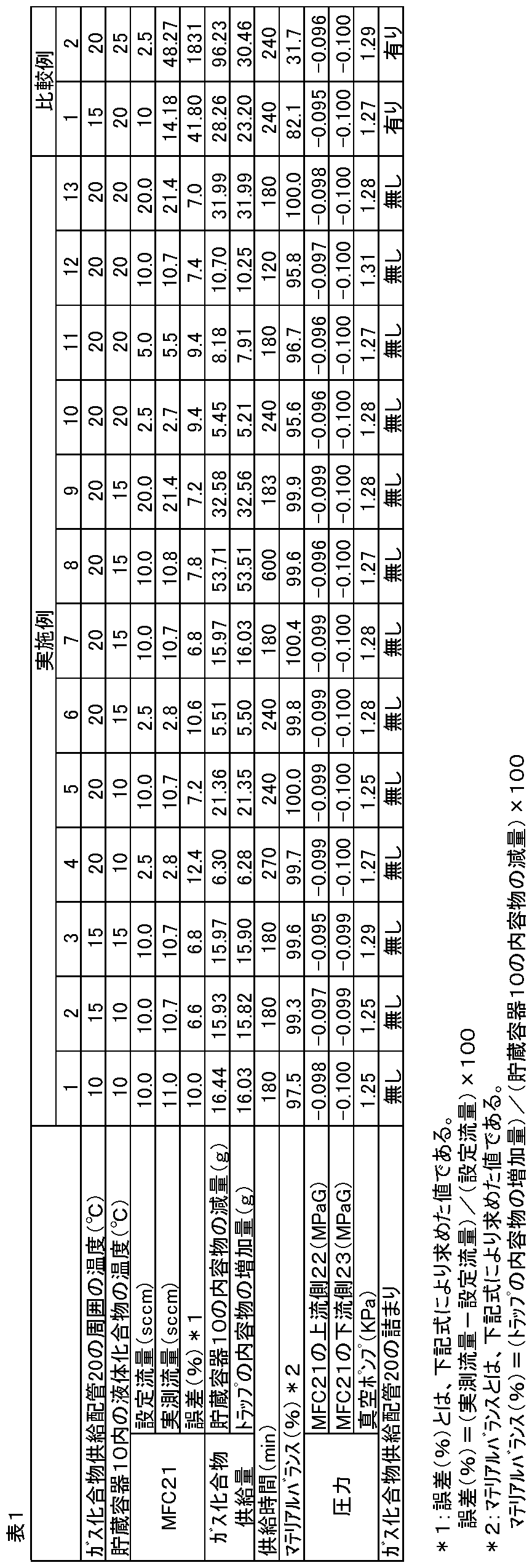
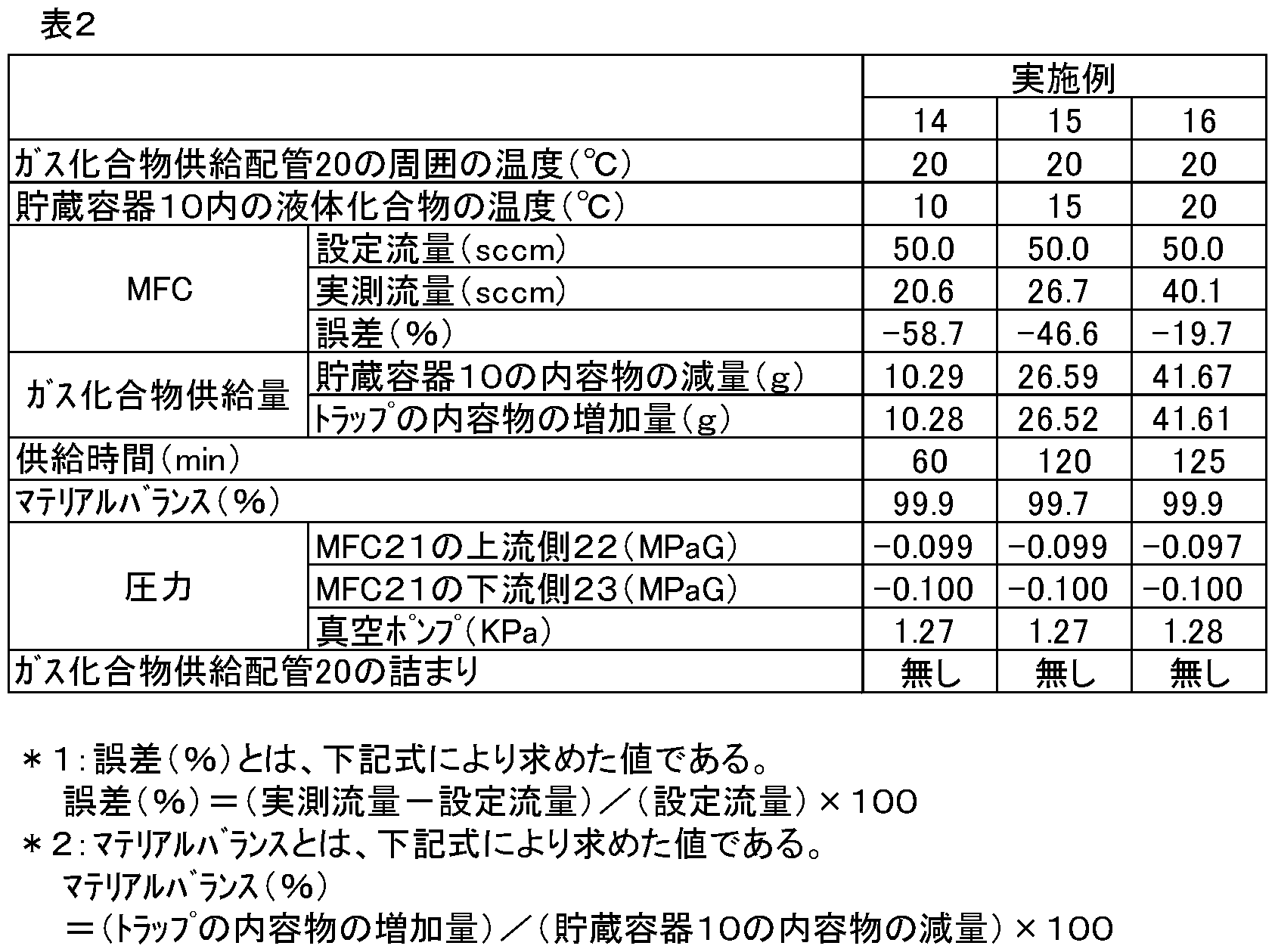
一方、比較例1~2によると、貯蔵容器10内の液体化合物の温度がガス化合物供給配管20の周囲の温度を超えているため、ガス化合物供給配管20内でガス化合物が凝縮し、ガス化合物供給配管20が詰まった。
10 貯蔵容器
11 貯蔵容器本体
12 接続配管
20 ガス化合物供給配管
21 マスフローコントローラー(MFC)
30、30A、30B、30C 温度制御装置
31 液体温度測定装置
32 周囲温度測定装置
33 液体温度測定装置
34 圧力測定装置
40、40A、40B、40C 伝熱装置
41 保温容器
42 熱媒体供給装置
45,45A,45B,45C 制御装置
50 収容室
100 対象箇所
Claims (21)
- 液体化合物から気化したガス化合物を対象箇所まで供給するためのガス供給装置であって、
前記液体化合物を収容可能な貯蔵容器と、
一端が前記貯蔵容器に接続されており、他端が前記対象箇所に配置可能となっているガス化合物供給配管と、
前記貯蔵容器内における前記ガス化合物又は液体化合物の温度を前記ガス化合物供給配管の周囲の温度以下に制御する温度制御装置と、
を有するガス供給装置。 - 前記温度制御装置は、
前記貯蔵容器内の前記液体化合物の温度を測定する液体温度測定装置、及び
前記液体温度測定装置で測定される測定温度に関する信号を受信し、前記測定温度が前記ガス化合物供給配管の周囲の温度以下になるように、前記貯蔵容器に対して熱の授受を行う伝熱装置、
を有する、請求項1に記載のガス供給装置。 - 前記温度制御装置は、
前記貯蔵容器内の前記ガス化合物の温度を測定するガス温度測定装置、及び
前記ガス温度測定装置で測定される測定温度に関する信号を受信し、前記測定温度が前記ガス化合物供給配管の周囲の温度以下になるように、前記貯蔵容器に対して熱の授受を行う伝熱装置、
を有する、請求項1又は2に記載のガス供給装置。 - 前記温度制御装置は、
前記貯蔵容器内の前記ガス化合物の圧力を測定する圧力測定装置、及び
前記圧力測定装置で測定される測定圧力に関する信号を受信し、前記測定圧力が、前記ガス化合物供給配管の周囲温度と同一温度における前記ガス化合物の飽和蒸気圧以下になるように、前記貯蔵容器に対して熱の授受を行う伝熱装置、
を有する、請求項1~3のいずれか1項に記載のガス供給装置。 - 前記ガス化合物供給配管の周囲の温度を測定し、前記周囲の温度に関する信号を前記伝熱装置に送信する周囲温度測定装置を有する、請求項1~4のいずれか1項に記載のガス供給装置。
- 前記貯蔵容器は、貯蔵容器本体と、前記貯蔵容器本体の前記ガス化合物が存在する領域と前記ガス化合物供給配管とを接続する接続配管とを有しており、
前記接続配管は、前記貯蔵容器本体側から前記ガス化合物供給配管側に向かって、水平よりも上方に傾斜している、請求項1~5のいずれか1項に記載のガス供給装置。 - 前記ガス化合物供給配管の途中に、マスフローコントローラーが設置されている、請求項1~6のいずれか1項に記載のガス供給装置。
- 前記貯蔵容器内におけるガス化合物の圧力は、前記対象箇所の圧力よりも高い、請求項1~7のいずれか1項に記載のガス供給装置。
- 前記貯蔵容器、前記温度制御装置及び前記ガス化合物供給配管を収容する、収納容器又は収容室を有する、請求項1~8のいずれか1項に記載のガス供給装置。
- 前記収納容器又は収容室は、前記収納容器又は収容室の内部空間の温度を制御する空調装置を有する、請求項9に記載のガス供給装置。
- 貯蔵容器内に収容された液体化合物から気化したガス化合物を、ガス化合物供給配管を介して対象箇所まで供給するガス供給方法であって、
前記貯蔵容器内の液体化合物又はガス化合物の温度を、前記ガス化合物供給配管の周囲の温度以下に制御する、ガス供給方法。 - 下記の初期運転工程を有する、請求項11に記載のガス供給方法。
初期運転工程:前記貯蔵容器を冷却して、前記貯蔵容器内の前記液体化合物又はガス化合物の温度を前記ガス化合物供給配管の周囲の温度以下に制御した後、前記貯蔵容器内の前記ガス化合物を、前記ガス化合物供給配管を介して対象箇所まで供給する工程。 - 下記の定常運転工程を有する、請求項11又は12に記載のガス供給方法。
定常運転工程:前記貯蔵容器内の前記ガス化合物を、前記ガス化合物供給配管を介して対象箇所まで供給すると共に、前記液体化合物の気化によって消費された熱エネルギーを前記貯蔵容器内に補給する工程。 - 前記貯蔵容器内の前記液体化合物又はガス化合物の温度を設定温度範囲内に制御するガス供給方法であって、
前記設定温度範囲の上限値は、前記ガス化合物供給配管の周囲の温度以下の特定値である、請求項11~13のいずれか1項に記載のガス供給方法。 - 前記貯蔵容器内の前記液体化合物又はガス化合物の温度が前記設定温度範囲の上限値に達したときに、前記貯蔵容器を冷却する、請求項14に記載のガス供給方法。
- 前記設定温度範囲の上限値は5~40℃の範囲内の特定値であり、
前記設定温度範囲の下限値は5~40℃の範囲内の特定値であり、
前記貯蔵容器内の気圧における前記液体化合物の沸点が、前記上限値よりも高く、
前記貯蔵容器内の気圧における前記液体化合物の融点が、前記下限値よりも低い、請求項14又は15に記載のガス供給方法。 - 前記貯蔵容器内に収容された前記液体化合物の温度を測定し、前記測定温度に基づいて、前記液体化合物への熱の授受を行うことにより、前記液体化合物の測定温度を設定温度範囲内に制御するガス供給方法であって、
前記設定温度範囲の上限値は、前記ガス化合物供給配管の周囲の温度以下の特定値である、請求項11~16のいずれか1項に記載のガス供給方法。 - 前記貯蔵容器内に存在するガス化合物の温度を測定し、前記測定温度に基づいて、前記液体化合物への熱の授受を行うことにより、前記ガス化合物の測定温度を設定温度範囲内に制御するガス供給方法であって、
前記設定温度範囲の上限値は、前記ガス化合物供給配管の周囲の温度以下の特定値である、請求項11~17のいずれか1項に記載のガス供給方法。 - 前記貯蔵容器内に存在するガス化合物の圧力を測定し、
前記貯蔵容器内に存在するガス化合物の圧力が、前記ガス供給配管の周囲の温度と同一温度に設定した場合における前記液体化合物の飽和蒸気圧以下となるように、前記液体化合物への熱の授受を制御することにより、前記ガス化合物又は液体化合物の測定温度を設定温度範囲内に制御する、請求項11~18のいずれか1項に記載のガス供給方法。 - 請求項1~10のいずれか1項に記載のガス供給装置を用いた、請求項11~19のいずれか1項に記載のガス供給方法。
- 対象箇所が、CVD装置又はエッチング装置である、請求項11~20のいずれか1項に記載のガス供給方法。
Priority Applications (6)
| Application Number | Priority Date | Filing Date | Title |
|---|---|---|---|
| US16/318,645 US11427907B2 (en) | 2016-07-20 | 2017-07-11 | Gas supply apparatus and gas supply method |
| CN201780044746.4A CN109477613B (zh) | 2016-07-20 | 2017-07-11 | 气体供给装置和气体供给方法 |
| KR1020197001592A KR102259628B1 (ko) | 2016-07-20 | 2017-07-11 | 가스 공급 장치 및 가스 공급 방법 |
| EP17830895.3A EP3489569B1 (en) | 2016-07-20 | 2017-07-11 | Gas supply apparatus and gas supply method |
| JP2018528496A JP6958914B2 (ja) | 2016-07-20 | 2017-07-11 | ガス供給装置及びガス供給方法 |
| US17/725,655 US20220251703A1 (en) | 2016-07-20 | 2022-04-21 | Gas supply apparatus and gas supply method |
Applications Claiming Priority (2)
| Application Number | Priority Date | Filing Date | Title |
|---|---|---|---|
| JP2016142652 | 2016-07-20 | ||
| JP2016-142652 | 2016-07-20 |
Related Child Applications (2)
| Application Number | Title | Priority Date | Filing Date |
|---|---|---|---|
| US16/318,645 A-371-Of-International US11427907B2 (en) | 2016-07-20 | 2017-07-11 | Gas supply apparatus and gas supply method |
| US17/725,655 Division US20220251703A1 (en) | 2016-07-20 | 2022-04-21 | Gas supply apparatus and gas supply method |
Publications (1)
| Publication Number | Publication Date |
|---|---|
| WO2018016375A1 true WO2018016375A1 (ja) | 2018-01-25 |
Family
ID=60992981
Family Applications (1)
| Application Number | Title | Priority Date | Filing Date |
|---|---|---|---|
| PCT/JP2017/025214 WO2018016375A1 (ja) | 2016-07-20 | 2017-07-11 | ガス供給装置及びガス供給方法 |
Country Status (7)
| Country | Link |
|---|---|
| US (2) | US11427907B2 (ja) |
| EP (1) | EP3489569B1 (ja) |
| JP (1) | JP6958914B2 (ja) |
| KR (1) | KR102259628B1 (ja) |
| CN (1) | CN109477613B (ja) |
| TW (1) | TWI671803B (ja) |
| WO (1) | WO2018016375A1 (ja) |
Cited By (2)
| Publication number | Priority date | Publication date | Assignee | Title |
|---|---|---|---|---|
| US11896918B2 (en) | 2020-04-24 | 2024-02-13 | Central Glass Company, Limited | Composition supply method, composition, supply device, and composition filling method |
| JP7485922B2 (ja) | 2020-04-24 | 2024-05-17 | セントラル硝子株式会社 | 組成物の供給方法、組成物、供給装置及び組成物の充填方法 |
Families Citing this family (1)
| Publication number | Priority date | Publication date | Assignee | Title |
|---|---|---|---|---|
| CN115493082B (zh) * | 2022-09-15 | 2023-08-01 | 四川红华实业有限公司 | 电子级别三氟化氯供料系统和方法、收料系统和方法 |
Citations (7)
| Publication number | Priority date | Publication date | Assignee | Title |
|---|---|---|---|---|
| JPH0160938B2 (ja) | 1981-03-20 | 1989-12-26 | Sharp Kk | |
| JPH04132300U (ja) * | 1991-05-27 | 1992-12-07 | 京セラ株式会社 | 液化ガス気化装置 |
| JPH07161638A (ja) | 1993-12-03 | 1995-06-23 | Fuji Electric Co Ltd | 気相成長装置の有機金属化合物ガス供給装置 |
| JP2003268551A (ja) | 2002-03-14 | 2003-09-25 | Furukawa Co Ltd | Cvd装置の原料供給装置 |
| JP2003332327A (ja) | 2002-05-16 | 2003-11-21 | Japan Pionics Co Ltd | 気化供給方法 |
| JP2008172184A (ja) | 2006-02-23 | 2008-07-24 | Tokyo Electron Ltd | プラズマエッチング方法、プラズマエッチング装置、制御プログラム及びコンピュータ記憶媒体 |
| JP2013113151A (ja) * | 2011-11-25 | 2013-06-10 | Toyota Motor Corp | エンジンの暖機装置 |
Family Cites Families (18)
| Publication number | Priority date | Publication date | Assignee | Title |
|---|---|---|---|---|
| US3031887A (en) * | 1960-12-01 | 1962-05-01 | Herrick L Johnston Inc | Device for measurement of liquid level or volume of liquefied gases |
| JPS6460938A (en) | 1987-09-01 | 1989-03-08 | Hitachi Ltd | Cathode for electron tube |
| US6076359A (en) * | 1996-11-25 | 2000-06-20 | American Air Liquide Inc. | System and method for controlled delivery of liquified gases |
| US6004433A (en) | 1997-02-03 | 1999-12-21 | L'air Liquide Societe Anonyme Pour L'etude Et L'exploitation Des Procedes George Claude | Purification of electronic specialty gases by vapor phase transfilling |
| US6199384B1 (en) * | 1999-07-09 | 2001-03-13 | American Air Liquide Inc. | System and method for controlled delivery of liquefied gases including control aspects |
| JP2001023974A (ja) | 1999-07-12 | 2001-01-26 | Sony Corp | 半導体装置の製造装置 |
| US6581623B1 (en) * | 1999-07-16 | 2003-06-24 | Advanced Technology Materials, Inc. | Auto-switching gas delivery system utilizing sub-atmospheric pressure gas supply vessels |
| US6363728B1 (en) * | 2000-06-20 | 2002-04-02 | American Air Liquide Inc. | System and method for controlled delivery of liquefied gases from a bulk source |
| US6443435B1 (en) * | 2000-10-23 | 2002-09-03 | Applied Materials, Inc. | Vaporization of precursors at point of use |
| US20020124575A1 (en) * | 2001-01-05 | 2002-09-12 | Atul Pant | Gas delivery at high flow rates |
| AUPR728501A0 (en) * | 2001-08-27 | 2001-09-20 | Johns, Bradley Charles | Apparatus for dispensing a vapour into an air flow |
| CN101230948A (zh) | 2007-01-24 | 2008-07-30 | 力晶半导体股份有限公司 | 气柜温度控制系统及其控制方法 |
| US20110225986A1 (en) * | 2010-03-22 | 2011-09-22 | Justin Cole Germond | Systems and methods for gas supply and usage |
| US9347614B2 (en) * | 2010-04-21 | 2016-05-24 | Honda Motor Co., Ltd. | Method and system for tank refilling using active fueling speed control |
| KR101287113B1 (ko) | 2010-06-30 | 2013-07-17 | 삼성디스플레이 주식회사 | 증착 장치용 캐니스터 및 이를 이용한 증착 장치 |
| KR101883360B1 (ko) | 2011-03-28 | 2018-07-30 | 어플라이드 머티어리얼스, 인코포레이티드 | 에피택셜 게르마늄 스트레서 합금들의 선택적 증착을 위한 방법 및 장치 |
| US8776821B2 (en) | 2011-05-24 | 2014-07-15 | Rohm And Haas Electronic Materials Llc | Vapor delivery device, methods of manufacture and methods of use thereof |
| US9970108B2 (en) | 2014-08-01 | 2018-05-15 | Lam Research Corporation | Systems and methods for vapor delivery in a substrate processing system |
-
2017
- 2017-07-11 EP EP17830895.3A patent/EP3489569B1/en active Active
- 2017-07-11 WO PCT/JP2017/025214 patent/WO2018016375A1/ja active Application Filing
- 2017-07-11 US US16/318,645 patent/US11427907B2/en active Active
- 2017-07-11 JP JP2018528496A patent/JP6958914B2/ja active Active
- 2017-07-11 CN CN201780044746.4A patent/CN109477613B/zh active Active
- 2017-07-11 KR KR1020197001592A patent/KR102259628B1/ko active IP Right Grant
- 2017-07-13 TW TW106123430A patent/TWI671803B/zh active
-
2022
- 2022-04-21 US US17/725,655 patent/US20220251703A1/en active Pending
Patent Citations (7)
| Publication number | Priority date | Publication date | Assignee | Title |
|---|---|---|---|---|
| JPH0160938B2 (ja) | 1981-03-20 | 1989-12-26 | Sharp Kk | |
| JPH04132300U (ja) * | 1991-05-27 | 1992-12-07 | 京セラ株式会社 | 液化ガス気化装置 |
| JPH07161638A (ja) | 1993-12-03 | 1995-06-23 | Fuji Electric Co Ltd | 気相成長装置の有機金属化合物ガス供給装置 |
| JP2003268551A (ja) | 2002-03-14 | 2003-09-25 | Furukawa Co Ltd | Cvd装置の原料供給装置 |
| JP2003332327A (ja) | 2002-05-16 | 2003-11-21 | Japan Pionics Co Ltd | 気化供給方法 |
| JP2008172184A (ja) | 2006-02-23 | 2008-07-24 | Tokyo Electron Ltd | プラズマエッチング方法、プラズマエッチング装置、制御プログラム及びコンピュータ記憶媒体 |
| JP2013113151A (ja) * | 2011-11-25 | 2013-06-10 | Toyota Motor Corp | エンジンの暖機装置 |
Non-Patent Citations (1)
| Title |
|---|
| See also references of EP3489569A4 |
Cited By (2)
| Publication number | Priority date | Publication date | Assignee | Title |
|---|---|---|---|---|
| US11896918B2 (en) | 2020-04-24 | 2024-02-13 | Central Glass Company, Limited | Composition supply method, composition, supply device, and composition filling method |
| JP7485922B2 (ja) | 2020-04-24 | 2024-05-17 | セントラル硝子株式会社 | 組成物の供給方法、組成物、供給装置及び組成物の充填方法 |
Also Published As
| Publication number | Publication date |
|---|---|
| EP3489569A1 (en) | 2019-05-29 |
| JPWO2018016375A1 (ja) | 2019-05-09 |
| KR20190020063A (ko) | 2019-02-27 |
| US20190292660A1 (en) | 2019-09-26 |
| KR102259628B1 (ko) | 2021-06-02 |
| EP3489569B1 (en) | 2023-01-18 |
| CN109477613B (zh) | 2021-11-19 |
| EP3489569A4 (en) | 2020-03-25 |
| US11427907B2 (en) | 2022-08-30 |
| TWI671803B (zh) | 2019-09-11 |
| CN109477613A (zh) | 2019-03-15 |
| US20220251703A1 (en) | 2022-08-11 |
| TW201810381A (zh) | 2018-03-16 |
| JP6958914B2 (ja) | 2021-11-02 |
Similar Documents
| Publication | Publication Date | Title |
|---|---|---|
| US20220251703A1 (en) | Gas supply apparatus and gas supply method | |
| KR102410536B1 (ko) | 원자 층 식각 공정 | |
| CN103180275B (zh) | 2,3,3,3-四氟丙烯的制备方法 | |
| CN112105594B (zh) | 1,2-二氟乙烯和/或1,1,2-三氟乙烷的制造方法 | |
| JP5059831B2 (ja) | 反応性の液を基にしたガス貯蔵及び送給装置 | |
| KR101620588B1 (ko) | 2,3,3,3-테트라플루오로프로펜 제조 방법 | |
| TW201738954A (zh) | 使用電漿與蒸氣處理組合之al2o3的原子層蝕刻 | |
| CN105742157A (zh) | 氧化锗预清洁模块和方法 | |
| US20050020071A1 (en) | Method and apparatus for cleaning and method and apparatus for etching | |
| CN105026348A (zh) | 用于生产氯化烷烃的方法 | |
| CN105037080A (zh) | 延长氢氟化过程中的催化剂寿命的方法 | |
| JP5780007B2 (ja) | 含フッ素プロペンの製造方法 | |
| CN103937460A (zh) | 包含1,1,1,2,3-五氟丙烷或2,3,3,3-四氟丙烯的组合物 | |
| KR20070094924A (ko) | 할로카본 제조방법, 할로카본 분리방법, 및 할로카본제조시스템 | |
| KR102234857B1 (ko) | Hcfc-244bb로의 hcfo-1233xf 불화수소화 동안 hfc-245cb 형성을 완화시키는 방법 | |
| US20220144729A1 (en) | Process for manufacture of 2-chloro-1,1,1-trifluoropropene | |
| TW201331155A (zh) | 製造2,3,3,3-四氟丙烯之方法 | |
| US20230242466A1 (en) | Methods for producing halogenated alkene compound and fluorinated alkyne compound | |
| CN103180276A (zh) | 通过五氯丙烷的气相氟化制造2-氯-3,3,3-三氟丙烯的方法 | |
| JP2021138705A (ja) | ハロゲン化アルケン化合物及びフッ化アルキン化合物の製造方法 | |
| US9029616B2 (en) | Process for 1-chloro-3,3,3-trifluoropropene from trifluoromethane | |
| US9150480B2 (en) | Synthesis of fluorinated ethers | |
| CN113661154A (zh) | 用于制备z-1,1,1,4,4,4-六氟丁-2-烯的方法以及用于制备其的中间体 | |
| TWI836011B (zh) | 鹵化炔化合物之製造方法及鹵化烯化合物之製造方法 | |
| JP2017178897A (ja) | クロロプロパン類の製造方法 |
Legal Events
| Date | Code | Title | Description |
|---|---|---|---|
| WWE | Wipo information: entry into national phase |
Ref document number: 2018528496 Country of ref document: JP |
|
| 121 | Ep: the epo has been informed by wipo that ep was designated in this application |
Ref document number: 17830895 Country of ref document: EP Kind code of ref document: A1 |
|
| ENP | Entry into the national phase |
Ref document number: 20197001592 Country of ref document: KR Kind code of ref document: A |
|
| NENP | Non-entry into the national phase |
Ref country code: DE |
|
| ENP | Entry into the national phase |
Ref document number: 2017830895 Country of ref document: EP Effective date: 20190220 |