WO2018012146A1 - 電力変換装置、及び電力変換装置の制御方法 - Google Patents
電力変換装置、及び電力変換装置の制御方法 Download PDFInfo
- Publication number
- WO2018012146A1 WO2018012146A1 PCT/JP2017/020950 JP2017020950W WO2018012146A1 WO 2018012146 A1 WO2018012146 A1 WO 2018012146A1 JP 2017020950 W JP2017020950 W JP 2017020950W WO 2018012146 A1 WO2018012146 A1 WO 2018012146A1
- Authority
- WO
- WIPO (PCT)
- Prior art keywords
- voltage
- power conversion
- value
- unit
- current
- Prior art date
- Legal status (The legal status is an assumption and is not a legal conclusion. Google has not performed a legal analysis and makes no representation as to the accuracy of the status listed.)
- Ceased
Links
Images



Classifications
-
- H—ELECTRICITY
- H02—GENERATION; CONVERSION OR DISTRIBUTION OF ELECTRIC POWER
- H02M—APPARATUS FOR CONVERSION BETWEEN AC AND AC, BETWEEN AC AND DC, OR BETWEEN DC AND DC, AND FOR USE WITH MAINS OR SIMILAR POWER SUPPLY SYSTEMS; CONVERSION OF DC OR AC INPUT POWER INTO SURGE OUTPUT POWER; CONTROL OR REGULATION THEREOF
- H02M3/00—Conversion of DC power input into DC power output
- H02M3/02—Conversion of DC power input into DC power output without intermediate conversion into AC
- H02M3/04—Conversion of DC power input into DC power output without intermediate conversion into AC by static converters
- H02M3/10—Conversion of DC power input into DC power output without intermediate conversion into AC by static converters using discharge tubes with control electrode or semiconductor devices with control electrode
- H02M3/145—Conversion of DC power input into DC power output without intermediate conversion into AC by static converters using discharge tubes with control electrode or semiconductor devices with control electrode using devices of a triode or transistor type requiring continuous application of a control signal
- H02M3/155—Conversion of DC power input into DC power output without intermediate conversion into AC by static converters using discharge tubes with control electrode or semiconductor devices with control electrode using devices of a triode or transistor type requiring continuous application of a control signal using semiconductor devices only
- H02M3/156—Conversion of DC power input into DC power output without intermediate conversion into AC by static converters using discharge tubes with control electrode or semiconductor devices with control electrode using devices of a triode or transistor type requiring continuous application of a control signal using semiconductor devices only with automatic control of output voltage or current, e.g. switching regulators
-
- H—ELECTRICITY
- H02—GENERATION; CONVERSION OR DISTRIBUTION OF ELECTRIC POWER
- H02M—APPARATUS FOR CONVERSION BETWEEN AC AND AC, BETWEEN AC AND DC, OR BETWEEN DC AND DC, AND FOR USE WITH MAINS OR SIMILAR POWER SUPPLY SYSTEMS; CONVERSION OF DC OR AC INPUT POWER INTO SURGE OUTPUT POWER; CONTROL OR REGULATION THEREOF
- H02M1/00—Details of apparatus for conversion
- H02M1/32—Means for protecting converters other than automatic disconnection
-
- H—ELECTRICITY
- H02—GENERATION; CONVERSION OR DISTRIBUTION OF ELECTRIC POWER
- H02M—APPARATUS FOR CONVERSION BETWEEN AC AND AC, BETWEEN AC AND DC, OR BETWEEN DC AND DC, AND FOR USE WITH MAINS OR SIMILAR POWER SUPPLY SYSTEMS; CONVERSION OF DC OR AC INPUT POWER INTO SURGE OUTPUT POWER; CONTROL OR REGULATION THEREOF
- H02M1/00—Details of apparatus for conversion
- H02M1/36—Means for starting or stopping converters
-
- H—ELECTRICITY
- H02—GENERATION; CONVERSION OR DISTRIBUTION OF ELECTRIC POWER
- H02M—APPARATUS FOR CONVERSION BETWEEN AC AND AC, BETWEEN AC AND DC, OR BETWEEN DC AND DC, AND FOR USE WITH MAINS OR SIMILAR POWER SUPPLY SYSTEMS; CONVERSION OF DC OR AC INPUT POWER INTO SURGE OUTPUT POWER; CONTROL OR REGULATION THEREOF
- H02M7/00—Conversion of AC power input into DC power output; Conversion of DC power input into AC power output
- H02M7/42—Conversion of DC power input into AC power output without possibility of reversal
- H02M7/44—Conversion of DC power input into AC power output without possibility of reversal by static converters
- H02M7/48—Conversion of DC power input into AC power output without possibility of reversal by static converters using discharge tubes with control electrode or semiconductor devices with control electrode
-
- H—ELECTRICITY
- H02—GENERATION; CONVERSION OR DISTRIBUTION OF ELECTRIC POWER
- H02M—APPARATUS FOR CONVERSION BETWEEN AC AND AC, BETWEEN AC AND DC, OR BETWEEN DC AND DC, AND FOR USE WITH MAINS OR SIMILAR POWER SUPPLY SYSTEMS; CONVERSION OF DC OR AC INPUT POWER INTO SURGE OUTPUT POWER; CONTROL OR REGULATION THEREOF
- H02M7/00—Conversion of AC power input into DC power output; Conversion of DC power input into AC power output
- H02M7/42—Conversion of DC power input into AC power output without possibility of reversal
- H02M7/44—Conversion of DC power input into AC power output without possibility of reversal by static converters
- H02M7/48—Conversion of DC power input into AC power output without possibility of reversal by static converters using discharge tubes with control electrode or semiconductor devices with control electrode
- H02M7/53—Conversion of DC power input into AC power output without possibility of reversal by static converters using discharge tubes with control electrode or semiconductor devices with control electrode using devices of a triode or transistor type requiring continuous application of a control signal
- H02M7/537—Conversion of DC power input into AC power output without possibility of reversal by static converters using discharge tubes with control electrode or semiconductor devices with control electrode using devices of a triode or transistor type requiring continuous application of a control signal using semiconductor devices only, e.g. single switched pulse inverters
- H02M7/5387—Conversion of DC power input into AC power output without possibility of reversal by static converters using discharge tubes with control electrode or semiconductor devices with control electrode using devices of a triode or transistor type requiring continuous application of a control signal using semiconductor devices only, e.g. single switched pulse inverters in a bridge configuration
- H02M7/53871—Conversion of DC power input into AC power output without possibility of reversal by static converters using discharge tubes with control electrode or semiconductor devices with control electrode using devices of a triode or transistor type requiring continuous application of a control signal using semiconductor devices only, e.g. single switched pulse inverters in a bridge configuration with automatic control of output voltage or current
-
- H—ELECTRICITY
- H02—GENERATION; CONVERSION OR DISTRIBUTION OF ELECTRIC POWER
- H02M—APPARATUS FOR CONVERSION BETWEEN AC AND AC, BETWEEN AC AND DC, OR BETWEEN DC AND DC, AND FOR USE WITH MAINS OR SIMILAR POWER SUPPLY SYSTEMS; CONVERSION OF DC OR AC INPUT POWER INTO SURGE OUTPUT POWER; CONTROL OR REGULATION THEREOF
- H02M1/00—Details of apparatus for conversion
- H02M1/0067—Converter structures employing plural converter units, other than for parallel operation of the units on a single load
- H02M1/007—Plural converter units in cascade
Definitions
- the present invention relates to a power conversion device and a method for controlling the power conversion device.
- This application claims priority based on Japanese Patent Application No. 2016-140442 filed on July 15, 2016, and incorporates all the descriptions described in the above Japanese application.
- a solar power generation system or a secondary battery system installed in a general home or the like includes a power conversion device that performs power conversion from direct current to alternating current (see, for example, Patent Document 1).
- a power conversion device includes a power conversion unit that is provided between a DC power source and an AC circuit, performs DC / AC power conversion, and a control unit that controls the power conversion unit,
- the control unit includes a determination unit that determines whether or not a starting current flows in the AC electric circuit, and an adjustment unit that adjusts the AC voltage by the power conversion unit based on a determination result of the determination unit.
- a method for controlling a power conversion device is a method for controlling a power conversion device including a power conversion unit that is provided between a DC power source and an AC circuit and performs DC / AC power conversion. And a determination step for determining whether or not a starting current has flowed through the AC circuit, and an adjustment step for adjusting the AC voltage by the power converter based on the determination result of the determination step.
- the present invention in addition to the power conversion device and the method for controlling the power conversion device, the present invention can also be realized as a computer program for causing a computer to execute.
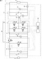
- FIG. 1 is an example of a circuit diagram of a power converter.
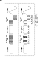
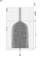
- FIG. 2 is a waveform diagram (horizontal writing) schematically showing the characteristics of the operation of the DC / DC converter and the inverter in the minimum switching conversion system.
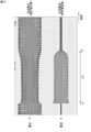
- FIG. 3 is a waveform diagram (vertical writing) schematically showing the operation characteristics of the DC / DC converter and the inverter in the minimum switching conversion system.
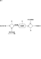
- FIG. 4 is a block diagram illustrating functions of the control unit.
- FIG. 5 is a control block diagram illustrating an aspect when the output voltage control unit controls the effective value of the AC voltage output from the power conversion unit.
- FIG. 1 is an example of a circuit diagram of a power converter.
- FIG. 2 is a waveform diagram (horizontal writing) schematically showing the characteristics of the operation of the DC / DC converter and the inverter in the minimum switching conversion system.
- FIG. 3 is a waveform diagram (vertical writing) schematically showing the operation characteristics of the DC / DC converter and the inverter in the minimum
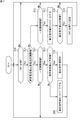
- FIG. 6 is a flowchart illustrating a start-up current suppression process performed by the determination unit and the adjustment unit of the control unit, and illustrates a process for detecting the start-up current and starting the start-up current suppression process.
- FIG. 7 is a flowchart illustrating the suppression process for the starting current performed by the determination unit and the adjustment unit of the control unit, and shows the execution of the starting current suppression process and the process up to the end.
- FIG. 8 is a graph showing a measurement result of the starting current flowing in the power conversion device in the verification.
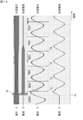
- FIG. 9 is an example of a graph showing the AC voltage output by the power converter when the starting current shown in FIG. 8 flows and the current flowing in the AC circuit.
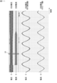
- FIG. 10 is an enlarged graph of the vicinity of the start timing Ts in FIG.
- FIG. 11 is an enlarged graph of the central portion of the period ⁇ T in FIG.
- FIG. 12 is an enlarged graph of the vicinity of the end timing Tf in FIG.
- an object is to provide a technique capable of suppressing the starting current.
- the starting current can be suppressed.
- a power conversion device includes a power conversion unit that is provided between a DC power supply and an AC circuit, and performs DC / AC power conversion, and a control unit that controls the power conversion unit.
- the control unit includes: a determination unit that determines whether or not a starting current has flowed through the AC circuit; and an adjustment unit that adjusts an AC voltage by the power conversion unit based on a determination result of the determination unit. I have.
- the AC voltage can be adjusted to be lowered by the power conversion unit, and the starting current can be suppressed.
- the power conversion unit is a DC / DC that is provided between the DC power source and a DC bus and boosts the DC voltage of the DC power source to a predetermined intermediate voltage.
- a converter, and an inverter connected between the DC bus and the AC circuit and converting the intermediate voltage into an AC voltage waveform, and the adjustment unit is configured to determine the DC / DC based on a determination result of the determination unit. It is preferable to adjust the voltage of the DC bus by the DC converter and the AC voltage. In this case, the AC voltage can be adjusted so as to suppress the starting current without increasing the DC voltage more than necessary.
- the control unit boosts the DC voltage by the DC / DC converter in one cycle of AC when generating the AC voltage from the DC voltage, and the inverter When to perform either non-inverted pass or inverted pass of polarity, and when to stop the DC / DC converter and step down by the inverter and perform either non-inverted pass or inverted pass of polarity
- the power conversion unit may be controlled to appear alternately. Even in this case, the AC voltage can be adjusted so as to suppress the starting current without increasing the DC voltage more than necessary.
- the said adjustment part controls the said power converter part so that the said alternating voltage may be adjusted in the zero cross vicinity. In this case, voltage fluctuation caused by adjusting the AC voltage can be suppressed.
- the determination unit determines whether or not the starting current flows based on a current flowing between the power conversion unit and the AC circuit, and the adjustment unit includes the determination
- the AC voltage by the power conversion unit may be adjusted based on a comparison result between the current and a preset overcurrent protection threshold together with the determination result of the unit. In this case, the starting current can be suppressed while considering the overcurrent.
- control method of the power converter device which is one Embodiment is provided between the direct-current power supply and the alternating current circuit, and the control method of the power converter device provided with the power converter part which performs direct current / alternate power conversion
- the method includes a determination step for determining whether or not a starting current has flowed through the AC circuit, and an adjustment step for adjusting the AC voltage by the power converter based on the determination result of the determination step. According to the determination method of the power conversion device having the above configuration, the starting current can be suppressed.
- the method for controlling the power conversion device can be realized by causing a computer included in the power conversion device to execute a computer program.
- the computer program is a computer program that is provided between a DC power supply and an AC power circuit, and causes the computer to execute control of a power conversion device including a power conversion unit that performs DC / AC power conversion.
- FIG. 1 is an example of a circuit diagram of a power converter.
- a power conversion device 1 is provided between a DC power source 2 and an AC circuit 3, and in a state where the DC voltage of the DC power source 2 is lower than the peak value (peak value) of the AC voltage of the AC circuit 3.
- the power converter 1 can supply, for example, AC power generated based on the DC power source 2 to the load 4 connected to the AC circuit 3 as an independent output.
- the power conversion device 1 includes a DC-side capacitor 5, a power conversion unit 20, an intermediate capacitor 9, and a filter circuit 11 as main circuit components.
- the power conversion unit 20 includes a DC / DC converter 6 and an inverter 10.
- the DC / DC converter 6 includes a DC reactor 7, a high-side switching element Q1, and a low-side switching element Q2, and constitutes a DC chopper circuit.
- the MOSFET switching elements Q1, Q2 have diodes (body diodes) d1, d2, respectively. Each switching element Q1, Q2 is controlled by the control unit 14.
- the high voltage side of the DC / DC converter 6 is connected to the DC bus 8.
- the intermediate capacitor 9 connected between the two lines of the DC bus 8 has a small capacity (100 ⁇ F or less, for example, several tens of ⁇ F), and exhibits a smoothing action for a voltage switched at a high frequency (for example, 20 kHz). However, it does not exert a smoothing action on a voltage that changes at a frequency (100 Hz or 120 Hz) that is about twice the commercial frequency.
- the inverter 10 connected to the DC bus 8 includes switching elements Q3 to Q6 that constitute a full bridge circuit.
- These switching elements Q3 to Q6 are, for example, MOSFETs.
- the switching elements Q3 to Q6 have diodes (body diodes) d3 to d6, respectively.
- the switching elements Q3 to Q6 are controlled by the control unit 14.
- a filter circuit 11 is provided between the inverter 10 and the AC circuit 3.
- the filter circuit 11 includes an AC reactor 12 and an AC side capacitor 13 provided on the load 4 side (right side in the figure) from the AC reactor 12.
- the filter circuit 11 prevents passage of high-frequency noise generated in the inverter 10 so as not to leak to the AC electric circuit 3 side.
- a voltage sensor 15 and a current sensor 16 are provided on the low voltage side (left side in the figure) of the DC / DC converter 6.
- the voltage sensor 15 is connected in parallel with the DC power supply 2 and detects the voltage across the DC power supply 2. Information on the detected voltage is provided to the control unit 14.
- the current sensor 16 detects a current flowing through the DC / DC converter 6. Information on the detected current is provided to the control unit 14.
- a voltage sensor 21 is provided on the high voltage side (right side in the figure) of the DC / DC converter 6.
- the voltage sensor 21 detects the voltage of the DC bus 8. Information on the detected voltage is provided to the control unit 14.
- a current sensor 17 for detecting a current flowing through the AC reactor 12 is provided on the AC side. Information on the current detected by the current sensor 17 is provided to the control unit 14.
- a voltage sensor 18 is provided in parallel with the AC capacitor 13.
- the current sensor 19 is provided in the electric circuit that connects the load 4 and the power conversion device 1. Information on the voltage detected by the voltage sensor 18 and information on the current detected by the current sensor 19 are respectively provided to the control unit 14.
- the said power converter device 1 performs only conversion from direct current
- the power conversion device 1 can charge the storage battery by performing conversion from AC to DC in addition to conversion from DC to AC. That is, the inverter 10 and the DC / DC converter 6 can each perform an operation of sending power in both directions.
- FIG. 2 and FIG. 3 are waveform diagrams simply showing the characteristics of the operation of the DC / DC converter 6 and the inverter 10 in the minimum switching conversion method. Although both figures show the same contents, FIG. 2 particularly displays the amplitude relationship from the DC input to the AC output so that it can be easily seen, and FIG. 3 particularly shows the control timing so that it can be easily seen.
- the upper part of FIG. 2 and the left column of FIG. 3 are waveform diagrams representing traditional switching control that is not the minimum switching conversion method, for comparison.
- 2 and the right column of FIG. 3 are waveform diagrams showing the operation of the minimum switching conversion method.
- the output at the interconnection point of the pair of switching elements of the DC / DC converter and the DC reactor with respect to the input DC voltage is It is in the form of an equidistant pulse train having a value higher than the DC voltage.
- This output is smoothed by an intermediate capacitor and appears as a voltage on the DC bus.
- the inverter performs PWM (Pulse Width Modulation) controlled switching while inverting the polarity in a half cycle. As a result, a sinusoidal AC voltage is obtained through final smoothing.
- PWM Pulse Width Modulation
- V ac * is a voltage target value at the AC output terminal of the inverter 10 in consideration of the influence of the filter circuit 11 on the current / voltage.
- V dc is a value that takes into account the voltage drop due to the DC reactor 7 to the voltage across the DC power supply 2.
- the intermediate capacitor 9 has a small capacity, a part of the waveform around the peak of the absolute value of the AC waveform remains without being smoothed. That is, the smoothing works to the extent that the trace of the high frequency switching by the DC / DC converter 6 is erased, but the intermediate capacitor 9 has a small capacity so that the low frequency about twice the commercial frequency cannot be smoothed. It has become.
- the inverter 10
- High-frequency switching is performed (“OP” in the figure), and when
- the inverter 10 When the high frequency switching is stopped, the inverter 10 has the switching elements Q3 and Q6 on, Q4 and Q5 off (non-inverted), the switching elements Q3 and Q6 off and Q4 and Q5 on ( By selecting one of (inversion), only necessary polarity inversion is performed.
- the output of the inverter 10 is smoothed by the AC reactor 12 and the AC side capacitor 13, and a desired AC output is obtained.
- the DC / DC converter 6 and the inverter 10 are alternately performing high-frequency switching operation, and when the DC / DC converter 6 is performing a boosting operation, The inverter 10 stops high-frequency switching and performs only necessary polarity inversion with respect to the voltage of the DC bus 8. Conversely, when the inverter 10 performs high-frequency switching operation, the DC / DC converter 6 stops and the voltage across the DC-side capacitor 5 appears on the DC bus 8 via the DC reactor 7 and the diode d1.
- Such a power conversion device 1 can reduce the overall number of high-frequency switching operations by generating a pause in the high-frequency switching of the switching elements Q1 to Q6. Thereby, the efficiency of power conversion can be improved significantly.
- FIG. 4 is a block diagram illustrating functions of the control unit 14.
- the control unit 14 controls the power conversion unit 20 (the DC / DC converter 6 and the inverter 10) by controlling the switching elements Q1 to Q6.
- the control unit 14 controls the power conversion unit 20 to perform power conversion by the minimum switching method.
- the control unit 14 can be configured by a computer including a CPU (Central Processing Unit), a storage unit, and the like, for example.
- the computer realizes each function, which will be described later, included in the control unit 14 by executing the computer program.
- the computer program is stored in the storage unit.
- the control unit 14 can be configured by a hardware-only circuit that does not include a computer.
- the control unit 14 includes a determination unit 25, an adjustment unit 26, and an output voltage control unit 27 as functional units realized by executing the computer program.
- the determination unit 25 has a function of determining whether or not a starting current has flowed through the AC circuit 3 (FIG. 1) based on current information provided from at least one of the current sensor 17 and the current sensor 19.
- the determination unit 25 obtains a measured value (measured current value) of the current flowing through the AC circuit 3 from the current information.
- the determination unit 25 determines whether or not the starting current has flowed through the AC circuit 3 by comparing the obtained measured current value with a preset starting current threshold value.
- the determination part 25 calculates
- the determination part 25 calculates
- the adjustment unit 26 has a function of adjusting the effective value of the AC voltage by the power conversion unit 20 based on the determination result of the determination unit 25.
- the output voltage control unit 27 has a function of controlling the effective value of the AC voltage output from the power conversion unit 20 based on the command value of the AC voltage to be output.
- FIG. 5 is a control block diagram illustrating an aspect when the output voltage control unit 27 controls the effective value of the AC voltage output from the power conversion unit 20.
- the output voltage control unit 27 includes a first adder 28, a compensator 29, and a second adder 30 as functional units for controlling the power conversion unit 20.
- the output voltage control unit 27 gives the first adder 28 the voltage command value related to the AC voltage and the measured effective value for the AC voltage output by the power conversion unit 20.
- the first adder 28 obtains an error amount that is a difference between the voltage command value and the measured effective value that is a feedback value.
- the voltage command value is a command value related to the effective value of the AC voltage.
- the first adder 28 provides the compensator 29 with an error amount between the voltage command value and the measured effective value.
- the compensator 29 outputs a control command for the power converter 20 based on the error amount.
- the compensator 29 outputs a control command that can converge the error amount and set the effective value of the AC voltage output from the power converter 1 as the voltage command value.
- the compensator 29 gives a control command to the second adder 30.
- a disturbance compensation value is given to the second adder 30 together with a control command.
- the disturbance compensation value is a value for previously compensating for an error that occurs in the control command due to disturbance in the control of the power conversion unit 20.
- the second adder 30 outputs a control command obtained by adding the disturbance compensation value.
- the output voltage control unit 27 controls the effective value of the AC voltage output by the power conversion unit 20 by giving the control command output by the second adder 30 to the power conversion unit 20.
- the adjustment unit 26 adjusts the AC voltage by the power conversion unit 20 by giving a voltage command value to the output voltage control unit 27 as necessary.
- the output voltage control unit 27 adopts the given voltage command value instead of the voltage command value used for the current control, and outputs the alternating current output from the power conversion unit 20. Controls the effective value of voltage.
- control command given to the power converter 20 by the output voltage controller 27 is given to each of the DC / DC converter 6 and the inverter 10.
- the DC / DC converter 6 outputs the voltage of the DC bus based on the given control command.
- the inverter 10 outputs an alternating voltage based on the given control command. Therefore, when the adjustment unit 26 gives the voltage command value to the output voltage control unit 27, a control command from the output voltage control unit 27 is given to each of the DC / DC converter 6 and the inverter 10. Therefore, the adjustment unit 26 adjusts the voltage of the DC bus by the DC / DC converter 6 and the AC voltage by the inverter 10.
- FIG. 6 and 7 are flowcharts showing a suppression process for the starting current, which is performed by the determination unit 25 and the adjustment unit 26 of the control unit 14.
- FIG. 6 shows a process for detecting the start current generation and starting the start current suppressing process.
- the control unit 14 determines whether or not a flag indicating whether or not the starting current suppression process is in an execution state in step S1 is OFF (step S1).
- This flag is memorize
- the flag is set to ON, it indicates that the starting current suppression process is in an execution state. Further, when the flag is set to OFF, it indicates that the starting current suppression process is not in an execution state.
- step S1 When it is determined in step S1 that the flag is not OFF (ON), the control unit 14 returns to step S1. Therefore, when the starting current suppression process is in the execution state, the control unit 14 repeats step S1 until the flag is set to ON and the starting current suppression process ends.
- the determination unit 25 of the control unit 14 compares the measured current value for the current flowing through the AC circuit 3 with the starting current threshold value, and the measured current value is the starting current. It is determined whether or not the threshold value is exceeded (step S2).
- the starting current threshold is a threshold for determining whether or not the starting current is flowing in the AC circuit 3, and is set to a value that can be determined that the starting current is flowing in the AC circuit 3. Therefore, the determination unit 25 can determine whether or not a starting current has flowed through the AC circuit 3.
- the starting current threshold is set to, for example, at least twice the rated current value. In the present embodiment, if the rating of the power conversion device 1 is 10 amperes, the starting current threshold is set to 23 amperes.
- step S2 If it is determined in step S2 that the measured current value is not equal to or greater than the starting current threshold, the determination unit 25 returns to step S1 again. Therefore, when the flag is set to OFF, the determination unit 25 repeats the determination of whether or not the measured current value is greater than or equal to the starting current threshold until it is determined that the measured current value is greater than or equal to the starting current threshold.
- the output voltage control unit 27 controls the effective value of the AC voltage output from the power conversion unit 20 using the initial value of the voltage command value.
- the initial value of the voltage command value is set to 101 volts, for example.
- the adjustment unit 26 gives the first set value, which is a value lower than the initial value, to the output voltage control unit 27 as a voltage command value (step S3). ).
- the output voltage control unit 27 changes the voltage command value used for control from the initial value to the first set value, and controls the effective value of the AC voltage output from the power conversion unit 20 to be the first set value. To do.
- the power converter device 1 can adjust so that the effective value of the alternating voltage which the power converter 20 outputs may be reduced, and can suppress the starting current generated immediately before.
- the first set value is set to a value that is lower than the initial value and that can effectively suppress the starting current when the starting current flows. In the present embodiment, the first set value is set to 80 volts, for example.
- step S4 sets the flag to ON (step S4), and returns to step S1. After the flag is set to ON, the determination in step S1 is repeated until the flag is set to OFF.
- control part 14 determines with the measured current value about the electric current which flows into the AC circuit 3 in step S2 being more than a starting current threshold value, it will reduce an alternating voltage by changing a voltage command value, and promptly Starting current suppression processing is started.
- the flowchart shown in FIG. 6 is a process for detecting the generation of the starting current and starting the starting current suppressing process. Therefore, it is necessary to execute processing at a relatively high frequency in order to quickly detect the occurrence of the starting current. For example, the processing shown in FIG. 6 is executed at 20 kHz (0.05 millisecond cycle).
- FIG. 7 is a flowchart showing the execution of the starting current suppression process and the process up to the end.
- the control unit 14 determines whether or not the flag is ON in step S10 (step S10). If the flag is not ON (is OFF), the starting current suppression process is not in the execution state, and therefore the control unit 14 returns to step S10 again and does not execute the processes after step S11.
- the determination unit 25 of the control unit 14 proceeds to step S11, the measured current value for the current flowing through the AC circuit 3, the overcurrent protection threshold value, Are compared to determine whether or not the measured current value is greater than or equal to the overcurrent protection threshold (step S11).
- the overcurrent protection threshold value is a threshold value for determining whether or not a current larger than the rating of the power conversion device 1 flows, and is set to a value slightly larger than the rated current value of the power conversion device 1. . In this embodiment, if the rating of the power conversion device 1 is 10 amperes as described above, the starting current threshold is set to 12 amperes.
- step S11 determines whether or not the state in which it is determined that the measured current value is greater than or equal to the overcurrent protection threshold continues for a certain period. (Step S12). In step S11, the determination unit 25 determines that the measured current value is equal to or greater than the overcurrent protection threshold based on the number of continuous determinations in which the measured current value is continuously determined to be equal to or greater than the overcurrent protection threshold. It is determined whether or not has continued for a certain period.
- the determination unit 25 determines that the predetermined period has not been continued, and returns to step S1.
- the determination unit 25 determines that the continuous determination has continued for a certain period, and proceeds to step S13.
- the predetermined number of times is set to the number of times that can ensure a period in which the measured current value can be stably obtained.
- the determination unit 25 includes the power conversion unit 20 (power conversion device 1). ) Determines whether or not the measured effective value for the AC voltage output is equal to or lower than a preset lower limit value (step S13). If it is determined in step S13 that the measured effective value is equal to or lower than the lower limit value, the adjustment unit 26 returns to step S1 without giving a voltage command value to the output voltage control unit 27 (step S15). Thereby, the output voltage control part 27 uses the voltage command value currently used for control as it is for control. Therefore, the voltage command value is maintained as it is, and the effective value of the AC voltage output from the power conversion unit 20 is also maintained as it is (step S15).
- step S13 If it is determined in step S13 that the measured effective value is not less than or equal to the lower limit value (the measured effective value is greater than the lower limit value), the adjustment unit 26 sets the voltage value to 1 from the current voltage command value given to the output voltage control unit 27.
- the voltage command value lowered by the step is given to the output voltage control unit 27, and the process returns to step S1 (step S14).
- the output voltage control unit 27 uses a voltage command value that is lower in voltage value by one step than the voltage command value that has been used for control so far.
- the voltage command value is adjusted so that the voltage value is lowered by one step, and the effective value of the AC voltage output from the power conversion unit 20 is also adjusted to be lowered by one step (step S14).
- the control unit 14 performs control so that the voltage command value is decreased step by step until the measured effective value is equal to or lower than the lower limit value (steps S11 to S15). ). If the voltage command value is lowered, the load 4 connected to the AC circuit 3 may be adversely affected such as insufficient input voltage. For this reason, a lower limit value is provided for the measured effective value, and control is performed so that the measured effective value does not fall below the lower limit value. Therefore, the lower limit value is set to a voltage value that does not affect the load 4. In this embodiment, it is set to 75 volts.
- one step which is an adjustment range for adjusting the voltage value of the voltage command value, is set to 2 volts, for example. Therefore, the adjustment unit 26 decreases the voltage command value by 2 volts in step S14.
- the adjustment unit 26 Immediately after it is determined that the starting current has flowed in the AC circuit 3, the adjustment unit 26 gives the first set value as the voltage command value to the output voltage control unit 27, and sets the voltage command value of the output voltage control unit 27 from the initial value to the first value. Change to 1 set value. When the voltage command value is further decreased from the first set value, the adjustment unit 26 performs control so as to decrease step by step as described above.
- the adjustment unit 26 adjusts the effective value of the AC voltage output from the power conversion unit 20 in step S14, the adjustment value of the AC voltage is adjusted in the vicinity of the zero cross in the AC waveform of the AC voltage.
- the power converter 20 is controlled. Thereby, the voltage fluctuation which arises by adjusting an alternating voltage can be suppressed.
- the “near zero cross” means a period before and after the zero cross timing including the zero cross timing in the AC waveform of the AC voltage and indicating an AC voltage that can be regarded as 0 volts.
- step S11 If it is determined in step S11 that the measured current value for the current flowing through the AC circuit 3 is not equal to or greater than the overcurrent protection threshold (is smaller than the overcurrent protection threshold), the determination unit 25 does not exceed the overcurrent protection threshold. It is determined whether or not the state determined to be continued for a certain period (step S16). In step S11, the determination unit 25 is in a constant state in which it is determined that the measured current value is not equal to or greater than the overcurrent protection threshold based on the number of continuous determinations that are continuously determined that the measured current value is not equal to or greater than the overcurrent protection threshold. It is determined whether or not the period continues.
- the determination unit 25 determines that the continuous determination has not been continued for a certain period, and returns to step S1.
- the determination unit 25 determines that the continuous determination has continued for a certain period, and proceeds to step S17.
- the predetermined number of times is the same as that in step S12, and is set to the number of times that a period can be secured so that the measured current value can be stably obtained.
- step S16 it is determined that the state in which the measured current value is not equal to or greater than the overcurrent protection threshold continues for a certain period, and when the process proceeds to step S17, the adjustment unit 26 supplies the output voltage control unit 27 with the current state.
- a voltage command value obtained by raising the voltage value by one step from the voltage command value is provided to the output voltage control unit 27 (step S17).
- the output voltage control unit 27 uses a voltage command value that is higher in voltage by one step than the voltage command value that has been used for control so far.
- the voltage command value is increased by one step, and the effective value of the AC voltage output from the power conversion unit 20 is adjusted so that the voltage value is increased by one step (step S17).
- the adjustment unit 26 also adjusts the effective value of the AC voltage output from the power conversion unit 20 in Step S17, as in Step S14, in the vicinity of the zero cross in the AC waveform of the AC voltage.
- the power conversion unit 20 is controlled so as to be adjusted.
- step S18 the determination unit 25 proceeds to step S18, and the voltage command value given to the output voltage control unit 27 is greater than or equal to the initial value. It is determined whether or not there is (step S18).
- step S18 When determining that the voltage command value given to the output voltage control unit 27 in step S18 is not equal to or greater than the initial value (smaller than the initial value), the determination unit 25 returns to step S1.
- step S18 When determining in step S18 that the voltage command value given to the output voltage control unit 27 is equal to or greater than the initial value, the control unit 14 proceeds to step S19, sets the flag to OFF, and returns to step S1.
- control unit 14 performs control so that the voltage command value is increased step by step until the voltage command value becomes equal to or greater than the initial value (steps S11, S16 to S16). S19).
- control unit 14 determines that the starting current flows in the AC circuit 3
- the control unit 14 adjusts the effective value of the AC voltage output from the power conversion unit 20 to be lowered. Further, the control unit 14 compares the measured current value with the overcurrent protection threshold value in Step S11, and sets the effective value of the AC voltage so that the measured current value does not exceed the overcurrent protection threshold value in Steps S11 to S19. Control to keep as high as possible.
- step S11 If the measured current value is not equal to or greater than the overcurrent protection threshold (step S11) and the voltage command value is equal to or greater than the initial value (step S18), it is determined that the starting current is not already flowing in the AC circuit 3. Can do. Therefore, when the control unit 14 determines that the voltage command value given to the output voltage control unit 27 in step S18 is greater than or equal to the initial value, the control unit 14 proceeds to step S19, sets the flag to OFF, and performs the starting current suppression process. End (step S19). Moreover, the adjustment part 26 makes the output voltage control part 27 control the effective value of the alternating voltage which the power converter part 20 outputs using the initial value of a voltage command value, when a starting current suppression process is complete
- the adjustment unit 26 determines that the starting current has flown through the AC circuit 3, the adjustment unit 26 adjusts the effective value of the AC voltage output from the power conversion unit 20 to be lowered.
- the measurement current value is adjusted.
- the overcurrent protection threshold value it is determined whether the effective value of the AC voltage output from the power converter 20 is adjusted to be lowered or adjusted to be raised.
- the power converter device 1 can suppress the starting current in consideration of the overcurrent flowing through the own device.
- the flowchart shown in FIG. 7 is a process showing the execution of the starting current suppression process and the process up to the end. That is, the process after the generation of the starting current is detected by the process of FIG. Therefore, there is no need to execute the process as frequently as the flowchart shown in FIG. For this reason, the process shown in FIG. 7 is performed at 50 Hz (0.02 second cycle).
- the adjustment unit 26 gives the first set value as the voltage command value to the output voltage control unit 27, and the output voltage control unit 27 The voltage command value is changed from the initial value to the first set value. Thereby, it can adjust so that the effective value of the alternating voltage which the power conversion part 20 outputs may be lowered
- the adjustment part 26 adjusts the voltage of the DC bus by the DC / DC converter 6, and the alternating voltage by the inverter 10, it suppresses starting current, without raising DC voltage more than necessary. AC voltage can be adjusted to
- the power conversion device 1 of the above embodiment employs the minimum switching conversion method, the AC voltage can be adjusted so as to suppress the starting current without increasing the DC voltage more than necessary.
- the adjustment unit 26 may adjust so as to increase the effective value of the AC voltage output from the power conversion unit 20.
- the predetermined period is set to a time sufficient to eliminate the starting current once generated.
- FIG. 8 is a graph showing a measurement result of the starting current flowing through the power conversion device 1 in the verification.
- the horizontal axis represents time, and the vertical axis represents current.
- the starting current flowing through the power conversion device 1 was generated by starting an electric motor (rated about 365 W) connected to the power conversion device 1 as a load. The starting current flows during a period ⁇ T in FIG. The period ⁇ T is about 3.2 seconds. After the elapse of the period ⁇ T, the electric motor is in a rated operation state, and a current of about 4 amperes flows. In the period ⁇ T in which the starting current flows, a current of 25 amperes flows at the peak current.
- FIG. 9 is an example of a graph showing the AC voltage output from the power converter 20 and the current flowing in the AC circuit 3 when the starting current shown in FIG. 8 flows.
- the upper stage shows the AC voltage output from the power conversion unit 20, and the lower stage shows the current flowing in the AC circuit 3.
- the horizontal axis indicates time, and a graph indicating AC voltage and a graph indicating current correspond to the time direction.
- the graph indicating the AC voltage indicates the measured voltage value for the AC voltage output from the power conversion unit 20. As described above, the measured voltage value is obtained based on the voltage information supplied from the voltage sensor 18.
- the graph indicating the current indicates the measured current value of the current flowing through the AC circuit 3. As described above, the measured current value is obtained based on the current information provided from at least one of the current sensor 17 and the current sensor 19.
- the starting current flows in the period ⁇ T. That is, the start current starts flowing at the start timing Ts of the period ⁇ T, and the start current flows at the end timing Tf of the period ⁇ T.
- the power conversion device 1 When determining that the measured current value is equal to or greater than the starting current threshold (step S2 in FIG. 6), the power conversion device 1 lowers the voltage command value from the initial value of 101 volts to the first set value of 80 volts (step S2). S3), starting current suppression processing is started. After that, the power conversion device 1 adjusts the effective value of the AC voltage output from the power conversion unit 20 by adjusting the voltage command value according to the measured current value. As a result, the effective value of the AC voltage is adjusted to gradually increase as the current value of the starting current gradually decreases.
- the AC voltage suddenly decreases at the start timing Ts. Thereafter, the AC voltage is maintained at a constant voltage, and it can be seen that the AC voltage gradually increases as the current (measured current value) decreases in the period before the end timing Tf. At the end timing Tf, the AC voltage has substantially the same value as the period before the start timing Ts.
- FIG. 10 is an enlarged graph of the vicinity of the start timing Ts in FIG.
- the upper part shows the entire graph showing the AC voltage and the current shown in FIG. 9 in the upper part
- the lower part shows the vicinity of the square portion C1 (start) in the graph showing the entire upper part.
- the graph which expanded the timing Ts vicinity) is shown.
- the voltage value shown in the graph indicating the AC voltage indicates a voltage command value used by the output voltage control unit 27 for control.
- the starting current starts to flow from the start timing Ts.
- the voltage command value at this time is 100 volts as shown in FIG.
- the voltage command value is lowered from 100 volts to 80 volts at timing T1.
- the power conversion device 1 determines that the measured current value is equal to or greater than the starting current threshold (step S2 in FIG. 6), and the voltage command value is first set from 100 volts at the timing T1. This is because the value is lowered to 80 volts, which is the value (step S3 in FIG. 6), and the starting current suppression process is started.
- the voltage command value is lowered from 80 volts to 78 volts in the vicinity of timing T2, which is the timing of zero crossing when the graph indicating the AC voltage changes from negative to positive.
- the voltage command value is lowered from 78 volts to 76 volts in the vicinity of timing T3 which is the zero cross timing, and the voltage command value is changed from 76 volts to 74 volts in the vicinity of timing T4 which is the zero cross timing.
- the power converter 1 adjusts so that the effective value of the alternating voltage output from the power converter 20 may be lowered by reducing the voltage command value as described above, and suppresses the starting current.
- the power conversion device 1 is configured such that the effective value of the AC voltage is adjusted in the vicinity of the zero-cross timing. For this reason, as shown in FIG. 10, at the timing when the voltage command value is lowered by 2 volts in the graph showing the alternating voltage, it is possible to confirm that the waveform is not disturbed and voltage fluctuation does not occur.
- FIG. 11 is a graph in which the central portion of the period ⁇ T in FIG. 9 is enlarged.
- the upper part shows the entire graph showing the AC voltage and the current shown in FIG. 9 in the upper part
- the lower part shows the vicinity of the square portion C2 (period) in the graph showing the entire upper part.
- the graph which expanded (center part of (DELTA) T) is shown.
- the graph showing the AC voltage has an effective value of 75 volts.
- the graph showing the current has a peak value of 12 amps.
- the power conversion device 1 adjusts the voltage command value so as to decrease (step S14 in FIG. 7) and performs measurement.
- the voltage command value is adjusted to increase (step S17 in FIG. 7). For this reason, the power conversion device 1 outputs from the power conversion unit 20 so that the measured current value becomes constant at the overcurrent protection threshold (12 amperes) as shown in FIG. 11 while the starting current flows.
- the effective value of the AC voltage to be adjusted is adjusted.
- the power converter device 1 maintains the voltage command value at that time, without changing a voltage command value, when a measurement effective value becomes below a lower limit (75 volts) (step S13 in FIG. 7) (FIG. 7). 7, step S15).
- the measured current value is the overcurrent protection threshold (12 amperes) when the effective value of the AC voltage is 75 V, which is the lower limit.
- the power conversion device 1 can suppress the starting current by adjusting the effective value of the AC voltage output from the power conversion unit 20 even when the starting current flows through the AC circuit 3. Furthermore, the power converter 1 adjusts the effective value of the alternating voltage output from the power converter 20 so that the measured current value becomes constant at 12 amperes. As a result, the starting current can be continuously suppressed.
- FIG. 12 is an enlarged graph of the vicinity of the end timing Tf in FIG.
- the upper part shows the entire graph showing the AC voltage and the current shown in FIG. 9 in the upper part
- the lower part shows the vicinity of the square part C2 (end) in the graph showing the entire upper part.
- the graph which expanded the timing Tf vicinity) is shown.
- the voltage value shown in the graph which shows an alternating voltage in FIG. 12 has shown the voltage command value which the output voltage control part 27 uses for control.
- the voltage command value is increased from 86 volts to 88 volts at timing T10, which is in the vicinity of the zero-cross timing when the graph indicating the AC voltage changes from negative to positive.
- the voltage command value is maintained at 88 volts at timing T11, which is the zero-cross timing, and the voltage command value is increased from 88 volts to 90 volts in the vicinity of timing T12, which is the zero-cross timing.
- step S11 in FIG. 7 the power conversion device 1 adjusts the voltage command value so as to increase by one step (2 volts) (FIG. 7). 7, step S17).
- the power converter 1 gradually increases the effective value of the AC voltage as the measured current value decreases as shown in FIG. Adjust as follows.
- the power conversion device 1 adjusts the effective value of the AC voltage in the vicinity of the zero-crossing timing, a disturbance or the like appears in the waveform at the timing when the voltage command value is increased by 2 volts in the graph showing the AC voltage in FIG. It can be confirmed that no voltage fluctuation occurs.
- the power converter 1 can be adjusted to reduce the effective value of the AC voltage output from the power converter 20 and can suppress the starting current.
- the power converter 1 thereafter adjusts the effective value of the AC voltage output from the power converter 20 so that the measured current value becomes constant at the overcurrent protection threshold (12 amperes). Thereby, it has also confirmed that the power converter device 1 can suppress a starting current continuously.
Landscapes
- Engineering & Computer Science (AREA)
- Power Engineering (AREA)
- Inverter Devices (AREA)
Abstract
直流電源2と交流電路3との間に設けられ、直流/交流の電力変換を行う電力変換部20と、電力変換部20を制御する制御部14と、を備えている。制御部14は、交流電路3に始動電流が流れたか否かを判定する判定部25と、判定部25の判定結果に基づいて、電力変換部20による交流電圧を調整する調整部26と、を備えている。
Description
本発明は、電力変換装置、及び電力変換装置の制御方法に関する。
本出願は、2016年7月15日出願の日本出願第2016-140442号に基づく優先権を主張し、前記日本出願に記載された全ての記載内容を援用するものである。
本出願は、2016年7月15日出願の日本出願第2016-140442号に基づく優先権を主張し、前記日本出願に記載された全ての記載内容を援用するものである。
一般家庭等に設置される太陽光発電システムや、2次電池システムは、直流から交流への電力変換を行う電力変換装置を備えている(例えば特許文献1参照)。
一実施形態である電力変換装置は、直流電源と交流電路との間に設けられ、直流/交流の電力変換を行う電力変換部と、前記電力変換部を制御する制御部と、を備え、前記制御部は、前記交流電路に始動電流が流れたか否かを判定する判定部と、前記判定部の判定結果に基づいて、前記電力変換部による交流電圧を調整する調整部と、を備えている。
また、一実施形態である電力変換装置の制御方法は、直流電源と交流電路との間に設けられ、直流/交流の電力変換を行う電力変換部を備えた電力変換装置の制御方法であって、前記交流電路に始動電流が流れたか否かを判定する判定ステップと、前記判定ステップの判定結果に基づいて、前記電力変換部による交流電圧を調整する調整ステップと、を含む。
また、一実施形態として、上記電力変換装置や電力変換装置の制御方法以外に、コンピュータに実行させるためのコンピュータプログラムとして実現することもできる。
[本開示が解決しようとする課題]
例えば、モータ等の負荷を交流電源に接続した場合、その瞬間に当該負荷を定格運転する場合よりも数倍から10倍の大きな電流、いわゆる始動電流が流れることがある。
上記電力変換装置の交流出力を電力系統等の外部交流電源に連系しないで、単独で負荷に電力を給電する自立運転を行う場合には、上記始動電流も電力変換装置から流れる。
これに対し、始動電流が流れることを許容しうる仕様で電力変換装置を構成しようとすると、半導体デバイスやケーブル等について必要以上に過剰な品質のものを選定することとなり、コストの上昇を招いてしまう。
このため、始動電流を抑制するための方法が望まれる。
例えば、モータ等の負荷を交流電源に接続した場合、その瞬間に当該負荷を定格運転する場合よりも数倍から10倍の大きな電流、いわゆる始動電流が流れることがある。
上記電力変換装置の交流出力を電力系統等の外部交流電源に連系しないで、単独で負荷に電力を給電する自立運転を行う場合には、上記始動電流も電力変換装置から流れる。
これに対し、始動電流が流れることを許容しうる仕様で電力変換装置を構成しようとすると、半導体デバイスやケーブル等について必要以上に過剰な品質のものを選定することとなり、コストの上昇を招いてしまう。
このため、始動電流を抑制するための方法が望まれる。
そこで、始動電流を抑制することができる技術を提供することを目的とする。
[本開示の効果]
本開示によれば、始動電流を抑制することができる。
本開示によれば、始動電流を抑制することができる。
以下、好ましい実施形態について図面を参照しながら説明する。
[実施形態の概要]
(1)一実施形態である電力変換装置は、直流電源と交流電路との間に設けられ、直流/交流の電力変換を行う電力変換部と、前記電力変換部を制御する制御部と、を備え、前記制御部は、前記交流電路に始動電流が流れたか否かを判定する判定部と、前記判定部の判定結果に基づいて、前記電力変換部による交流電圧を調整する調整部と、を備えている。
(1)一実施形態である電力変換装置は、直流電源と交流電路との間に設けられ、直流/交流の電力変換を行う電力変換部と、前記電力変換部を制御する制御部と、を備え、前記制御部は、前記交流電路に始動電流が流れたか否かを判定する判定部と、前記判定部の判定結果に基づいて、前記電力変換部による交流電圧を調整する調整部と、を備えている。
上記構成の電力変換装置によれば、交流電路に始動電流が流れたと判定すれば、電力変換部による交流電圧を下げるように調整することができ、始動電流を抑制することができる。
(2)上記電力変換装置において、前記電力変換部は、前記電力変換部は、前記直流電源とDCバスとの間に設けられ前記直流電源の直流電圧を所定の中間電圧に昇圧するDC/DCコンバータと、前記DCバスと前記交流電路との間に接続され前記中間電圧を交流電圧波形に変換するインバータと、を備え、前記調整部は、前記判定部の判定結果に基づいて、前記DC/DCコンバータによる前記DCバスの電圧と、前記交流電圧とを調整することが好ましい。
この場合、直流電圧を必要以上に昇圧させずに、始動電流を抑制するように交流電圧を調整することができる。
この場合、直流電圧を必要以上に昇圧させずに、始動電流を抑制するように交流電圧を調整することができる。
(3)また、上記電力変換装置において、前記制御部は、前記直流電圧から前記交流電圧を生成するにあたって、交流1サイクル内で、前記DC/DCコンバータにより前記直流電圧を昇圧し、前記インバータは極性の非反転通過及び反転通過のいずれか一方を行う時期、及び、前記DC/DCコンバータを停止して、前記インバータにより降圧並びに、極性の非反転通過及び反転通過のいずれか一方を行う時期が、交互に出現するよう前記電力変換部を制御するものであってもよい。
この場合においても、直流電圧を必要以上に昇圧させずに、始動電流を抑制するように交流電圧を調整することができる。
この場合においても、直流電圧を必要以上に昇圧させずに、始動電流を抑制するように交流電圧を調整することができる。
(4)また、前記調整部は、ゼロクロス近傍で前記交流電圧が調整されるように前記電力変換部を制御することが好ましい。
この場合、交流電圧を調整することにより生じる電圧変動を抑制することができる。
この場合、交流電圧を調整することにより生じる電圧変動を抑制することができる。
(5)上記電力変換装置において、前記判定部は、前記電力変換部と前記交流電路との間を流れる電流に基づいて前記始動電流が流れたか否かを判定し、前記調整部は、前記判定部の判定結果とともに、前記電流と、予め設定された過電流保護閾値との比較結果に基づいて前記電力変換部による交流電圧を調整するものであってもよい。
この場合、過電流を考慮しつつ始動電流を抑制することができる。
この場合、過電流を考慮しつつ始動電流を抑制することができる。
(6)また、一実施形態である電力変換装置の制御方法は、直流電源と交流電路との間に設けられ、直流/交流の電力変換を行う電力変換部を備えた電力変換装置の制御方法であって、前記交流電路に始動電流が流れたか否かを判定する判定ステップと、前記判定ステップの判定結果に基づいて、前記電力変換部による交流電圧を調整する調整ステップと、を含む。
上記構成の電力変換装置の判定方法によれば、始動電流を抑制することができる。
上記構成の電力変換装置の判定方法によれば、始動電流を抑制することができる。
また、上記電力変換装置の制御方法は、電力変換装置が備えるコンピュータにコンピュータプログラムを実行させることで実現することもできる。
すなわち、前記コンピュータプログラムは、直流電源と交流電路との間に設けられ、直流/交流の電力変換を行う電力変換部を備えた電力変換装置の制御をコンピュータに実行させるためのコンピュータプログラムであって、コンピュータに、前記交流電路に始動電流が流れたか否かを判定する判定ステップと、前記判定ステップの判定結果に基づいて、前記電力変換部が出力する交流電圧を調整する調整ステップと、を実行させるコンピュータプログラムである。
すなわち、前記コンピュータプログラムは、直流電源と交流電路との間に設けられ、直流/交流の電力変換を行う電力変換部を備えた電力変換装置の制御をコンピュータに実行させるためのコンピュータプログラムであって、コンピュータに、前記交流電路に始動電流が流れたか否かを判定する判定ステップと、前記判定ステップの判定結果に基づいて、前記電力変換部が出力する交流電圧を調整する調整ステップと、を実行させるコンピュータプログラムである。
[実施形態の詳細]
以下、好ましい実施形態について図面を参照しつつ説明する。
なお、以下に記載する各実施形態の少なくとも一部を任意に組み合わせてもよい。
〔電力変換装置の構成について〕
図1は、電力変換装置の回路図の一例である。図において、電力変換装置1は、直流電源2と交流電路3との間に設けられ、直流電源2の直流電圧が交流電路3の交流電圧のピーク値(波高値)より低い状態で、直流/交流の電力変換を行う。この電力変換装置1は、例えば、直流電源2に基づいて生成した交流電力を、自立出力として、交流電路3に接続された負荷4に供給することができる。
以下、好ましい実施形態について図面を参照しつつ説明する。
なお、以下に記載する各実施形態の少なくとも一部を任意に組み合わせてもよい。
〔電力変換装置の構成について〕
図1は、電力変換装置の回路図の一例である。図において、電力変換装置1は、直流電源2と交流電路3との間に設けられ、直流電源2の直流電圧が交流電路3の交流電圧のピーク値(波高値)より低い状態で、直流/交流の電力変換を行う。この電力変換装置1は、例えば、直流電源2に基づいて生成した交流電力を、自立出力として、交流電路3に接続された負荷4に供給することができる。
電力変換装置1は、主回路構成要素として、直流側コンデンサ5、電力変換部20、中間コンデンサ9、及び、フィルタ回路11を備えている。
電力変換部20は、DC/DCコンバータ6と、インバータ10とを含んでいる。
DC/DCコンバータ6は、直流リアクトル7と、ハイサイドのスイッチング素子Q1と、ローサイドのスイッチング素子Q2とを備え、直流チョッパ回路を構成している。スイッチング素子Q1,Q2としては例えば、MOSFET(Metal-Oxide-Semiconductor Field Effect Transistor)を使用することができる。MOSFETのスイッチング素子Q1,Q2はそれぞれ、ダイオード(ボディダイオード)d1,d2を有している。各スイッチング素子Q1,Q2は、制御部14により制御される。
電力変換部20は、DC/DCコンバータ6と、インバータ10とを含んでいる。
DC/DCコンバータ6は、直流リアクトル7と、ハイサイドのスイッチング素子Q1と、ローサイドのスイッチング素子Q2とを備え、直流チョッパ回路を構成している。スイッチング素子Q1,Q2としては例えば、MOSFET(Metal-Oxide-Semiconductor Field Effect Transistor)を使用することができる。MOSFETのスイッチング素子Q1,Q2はそれぞれ、ダイオード(ボディダイオード)d1,d2を有している。各スイッチング素子Q1,Q2は、制御部14により制御される。
DC/DCコンバータ6の高圧側は、DCバス8に接続されている。DCバス8の2線間に接続されている中間コンデンサ9は、小容量(100μF以下、例えば数十μF)であり、高周波(例えば20kHz)でスイッチングされた電圧に対しては平滑作用を発揮するが、商用周波数の2倍程度の周波数(100Hz又は120Hz)で変化する電圧に対しては平滑作用を発揮しない。
DCバス8に接続されたインバータ10は、フルブリッジ回路を構成するスイッチング素子Q3~Q6を備えている。これらスイッチング素子Q3~Q6は、例えば、MOSFETである。MOSFETの場合は、スイッチング素子Q3~Q6がそれぞれ、ダイオード(ボディダイオード)d3~d6を有している。各スイッチング素子Q3~Q6は、制御部14により制御される。
インバータ10と交流電路3との間には、フィルタ回路11が設けられている。フィルタ回路11は、交流リアクトル12と、交流リアクトル12より負荷4側(図の右側)に設けられた交流側コンデンサ13とを備えている。フィルタ回路11は、インバータ10で発生する高周波ノイズが交流電路3側へ漏れ出ないように、通過を阻止している。
計測用の回路要素としては、DC/DCコンバータ6の低圧側(図の左側)に、電圧センサ15及び電流センサ16が設けられている。電圧センサ15は直流電源2と並列接続され、直流電源2の両端電圧を検出する。検出された電圧の情報は、制御部14に提供される。電流センサ16は、DC/DCコンバータ6に流れる電流を検出する。検出された電流の情報は、制御部14に提供される。
また、DC/DCコンバータ6の高圧側(図の右側)に、電圧センサ21が設けられている。電圧センサ21はDCバス8の電圧を検出する。検出された電圧の情報は、制御部14に提供される。
また、DC/DCコンバータ6の高圧側(図の右側)に、電圧センサ21が設けられている。電圧センサ21はDCバス8の電圧を検出する。検出された電圧の情報は、制御部14に提供される。
一方、交流側には、交流リアクトル12に流れる電流を検出する電流センサ17が設けられている。電流センサ17によって検出された電流の情報は、制御部14に提供される。また、交流側コンデンサ13と並列に、電圧センサ18が設けられている。さらに、電流センサ19が、負荷4と電力変換装置1とを接続する電路に設けられている。電圧センサ18によって検出された電圧の情報、及び、電流センサ19によって検出された電流の情報は、それぞれ、制御部14に提供される。
なお、上記電力変換装置1は、直流電源2が太陽光発電パネルである場合には直流から交流への変換のみを行う。直流電源2が蓄電池である場合は、電力変換装置1は、直流から交流への変換のほか、交流から直流への変換を行って蓄電池を充電することができる。すなわち、インバータ10及びDC/DCコンバータ6は、それぞれ、双方向に電力を送る動作が可能である。
〔最小スイッチング変換方式〕
次に、上記の電力変換装置1において実行される最小スイッチング方式の動作について、その概要を説明する。
図2及び図3は、最小スイッチング変換方式における、DC/DCコンバータ6及びインバータ10の動作の特徴を簡略に示す波形図である。両図は同じ内容を示しているが、図2は特に、直流入力から交流出力までの振幅の関係が見やすいように表示し、図3は特に、制御のタイミングが見やすいように表示している。図2の上段及び図3の左欄はそれぞれ、比較のために、最小スイッチング変換方式ではない伝統的なスイッチング制御を表す波形図である。また、図2の下段及び図3の右欄はそれぞれ、最小スイッチング変換方式の動作を示す波形図である。
次に、上記の電力変換装置1において実行される最小スイッチング方式の動作について、その概要を説明する。
図2及び図3は、最小スイッチング変換方式における、DC/DCコンバータ6及びインバータ10の動作の特徴を簡略に示す波形図である。両図は同じ内容を示しているが、図2は特に、直流入力から交流出力までの振幅の関係が見やすいように表示し、図3は特に、制御のタイミングが見やすいように表示している。図2の上段及び図3の左欄はそれぞれ、比較のために、最小スイッチング変換方式ではない伝統的なスイッチング制御を表す波形図である。また、図2の下段及び図3の右欄はそれぞれ、最小スイッチング変換方式の動作を示す波形図である。
まず、図2の上段(又は図3の左欄)において、伝統的なスイッチング制御では、入力される直流電圧に対する、DC/DCコンバータの一対のスイッチング素子及び直流リアクトルの相互接続点での出力は、直流電圧よりも高い値の等間隔のパルス列状である。この出力は中間コンデンサによって平滑化され、DCバスの電圧として現れる。これに対してインバータは、PWM(Pulse Width Modulation)制御されたスイッチングを半周期で極性反転しながら行う。この結果、最終的な平滑化を経て、正弦波の交流電圧が得られる。
次に、図2の下段(又は図3の右欄)の最小スイッチング変換方式では、交流波形の電圧目標値Vac
*の瞬時値の絶対値と、入力である直流電圧Vdcとの比較結果に応じて、DC/DCコンバータ6とインバータ10とが動作する。ここで、Vac
*は、フィルタ回路11が電流・電圧に及ぼす影響を考慮した、インバータ10の交流側出力端での電圧目標値とする。Vdcは、直流電源2の両端電圧に、直流リアクトル7による電圧降下を考慮した値とする。電圧目標値Vac
*の絶対値において|Vac
*|<Vdc(又は|Vac
*|≦Vdc)のときは、DC/DCコンバータ6は停止し(図中の「ST」)、|Vac
*|≧Vdc(又は|Vac
*|>Vdc)のときは、DC/DCコンバータ6が昇圧動作を行う(図中の「OP」)。DC/DCコンバータ6の出力は中間コンデンサ9により平滑化され、DCバス8に、図示の電圧Vbusとして現れる。
ここで、中間コンデンサ9が小容量であることにより、交流波形の絶対値のピーク前後となる一部の波形が平滑化されずにそのまま残る。すなわち、平滑は、DC/DCコンバータ6による高周波のスイッチングの痕跡を消す程度には作用するが、商用周波数の2倍程度の低周波を平滑化することはできないように、中間コンデンサ9が小容量になっている。
これに対してインバータ10は、電圧目標値Vac
*の絶対値と、直流電圧Vdcとの比較結果に応じて、|Vac
*|<Vdc(又は|Vac
*|≦Vdc)のときは、高周波スイッチングを行い(図中の「OP」)、|Vac
*|≧Vdc(又は|Vac
*|>Vdc)のときは、高周波スイッチングを停止する(図中の「ST」)。高周波スイッチングを停止しているときのインバータ10は、スイッチング素子Q3,Q6がオン、Q4,Q5がオフの状態(非反転)と、スイッチング素子Q3,Q6がオフ、Q4,Q5がオンの状態(反転)のいずれかを選択することにより、必要な極性反転のみを行う。インバータ10の出力は交流リアクトル12及び交流側コンデンサ13により平滑化され、所望の交流出力が得られる。
ここで、図3の右欄に示すように、DC/DCコンバータ6とインバータ10とは、交互に高周波スイッチングの動作をしており、DC/DCコンバータ6が昇圧の動作をしているときは、インバータ10は高周波スイッチングを停止し、DCバス8の電圧に対して必要な極性反転のみを行っている。逆に、インバータ10が高周波スイッチング動作するときは、DC/DCコンバータ6は停止して、直流側コンデンサ5の両端電圧が、直流リアクトル7及びダイオードd1を介してDCバス8に現れる。
以上のようにして、DC/DCコンバータ6とインバータ10とによる最小スイッチング変換方式の動作が行われる。このような電力変換装置1は、スイッチング素子Q1~Q6の高周波スイッチングに休止期間が生じることによって、全体的な高周波スイッチング回数を減らすことができる。これにより、電力変換の効率を、大幅に改善することができる。
〔交流電圧の制御について〕
図4は、制御部14の機能を示すブロック図である。
制御部14は、スイッチング素子Q1~Q6を制御することで電力変換部20(DC/DCコンバータ6、及びインバータ10)を制御する。
制御部14は、上記最小スイッチング方式により電力変換を行うように電力変換部20を制御する。
図4は、制御部14の機能を示すブロック図である。
制御部14は、スイッチング素子Q1~Q6を制御することで電力変換部20(DC/DCコンバータ6、及びインバータ10)を制御する。
制御部14は、上記最小スイッチング方式により電力変換を行うように電力変換部20を制御する。
制御部14は例えば、CPU(Central Processing Unit)や記憶部等を含んだコンピュータによって構成することができる。この場合、コンピュータは、コンピュータプログラムを実行することにより、制御部14が有する後述する各機能を実現する。コンピュータプログラムは、前記記憶部に記憶される。また、例えば、コンピュータを含まないハードウェアのみの回路で制御部14を構成することも可能である。
制御部14は、上記コンピュータプログラムを実行することで実現される機能部として、判定部25と、調整部26と、出力電圧制御部27とを備えている。
判定部25は、電流センサ17及び電流センサ19の少なくとも一方から与えられる電流の情報に基づいて、交流電路3(図1)に始動電流が流れたか否かを判定する機能を有している。判定部25は、電流の情報から交流電路3に流れる電流の測定値(測定電流値)を求める。判定部25は、求めた測定電流値と、予め設定された始動電流閾値とを比較することで、交流電路3に始動電流が流れたか否かを判定する。
また判定部25は、電圧センサ18から与えられる電圧の情報に基づいて電力変換部20(電力変換装置1)が出力する交流電圧についての測定値(測定電圧値)を求める。さらに判定部25は、測定電圧値の実効値(測定実効値)を求める。
判定部25は、この測定実効値を後述する始動電流抑制処理に用いる。
判定部25は、この測定実効値を後述する始動電流抑制処理に用いる。
調整部26は、判定部25の判定結果に基づいて、電力変換部20による交流電圧の実効値を調整する機能を有している。
出力電圧制御部27は、出力すべき交流電圧の指令値に基づいて、電力変換部20が出力する交流電圧の実効値を制御する機能を有している。
出力電圧制御部27は、出力すべき交流電圧の指令値に基づいて、電力変換部20が出力する交流電圧の実効値を制御する機能を有している。
図5は、出力電圧制御部27が、電力変換部20が出力する交流電圧の実効値を制御する際の態様を示した制御ブロック図である。
出力電圧制御部27は、電力変換部20を制御するための機能部として、第1加算器28と、補償器29と、第2加算器30とを備えている。
出力電圧制御部27は、第1加算器28に、交流電圧に関する電圧指令値と、電力変換部20が出力する交流電圧についての測定実効値とを与える。
第1加算器28は、前記電圧指令値と、フィードバック値である前記測定実効値とが与えられると、これらの差である誤差量を求める。なお、前記電圧指令値は、交流電圧の実効値に関する指令値である。
出力電圧制御部27は、電力変換部20を制御するための機能部として、第1加算器28と、補償器29と、第2加算器30とを備えている。
出力電圧制御部27は、第1加算器28に、交流電圧に関する電圧指令値と、電力変換部20が出力する交流電圧についての測定実効値とを与える。
第1加算器28は、前記電圧指令値と、フィードバック値である前記測定実効値とが与えられると、これらの差である誤差量を求める。なお、前記電圧指令値は、交流電圧の実効値に関する指令値である。
第1加算器28は、前記電圧指令値と前記測定実効値との誤差量を補償器29に与える。
補償器29は、前記誤差量に基づいて電力変換部20に対する制御命令を出力する。補償器29は、前記誤差量が与えられると、当該誤差量を収束させて電力変換装置1が出力する交流電圧の実効値を電圧指令値にし得る制御命令を出力する。
補償器29は、制御命令を第2加算器30に与える。
補償器29は、前記誤差量に基づいて電力変換部20に対する制御命令を出力する。補償器29は、前記誤差量が与えられると、当該誤差量を収束させて電力変換装置1が出力する交流電圧の実効値を電圧指令値にし得る制御命令を出力する。
補償器29は、制御命令を第2加算器30に与える。
第2加算器30には、制御命令とともに、外乱補償値が与えられる。外乱補償値は、予め電力変換部20の制御において外乱により制御命令に生じる誤差を補償するための値である。
第2加算器30は、外乱補償値を加算した制御命令を出力する。
第2加算器30は、外乱補償値を加算した制御命令を出力する。
出力電圧制御部27は、第2加算器30が出力する制御命令を電力変換部20に与えることで、電力変換部20が出力する交流電圧の実効値を制御する。
図4に戻って、調整部26は、必要に応じて出力電圧制御部27に電圧指令値を与えることで、電力変換部20による交流電圧を調整する。
出力電圧制御部27は、調整部26から電圧指令値が与えられると、現状制御に用いている電圧指令値に代えて、与えられた電圧指令値を採用し、電力変換部20が出力する交流電圧の実効値を制御する。
出力電圧制御部27は、調整部26から電圧指令値が与えられると、現状制御に用いている電圧指令値に代えて、与えられた電圧指令値を採用し、電力変換部20が出力する交流電圧の実効値を制御する。
なお、出力電圧制御部27が電力変換部20に与える制御命令は、DC/DCコンバータ6及びインバータ10それぞれに与えられる。
DC/DCコンバータ6は、与えられた制御命令に基づいてDCバスの電圧を出力する。インバータ10は、与えられた制御命令に基づいて交流電圧を出力する。
よって、調整部26が電圧指令値を出力電圧制御部27に与えると、出力電圧制御部27による制御命令がDC/DCコンバータ6及びインバータ10それぞれに与えられる。
よって、調整部26は、DC/DCコンバータ6によるDCバスの電圧と、インバータ10による交流電圧とを調整する。
DC/DCコンバータ6は、与えられた制御命令に基づいてDCバスの電圧を出力する。インバータ10は、与えられた制御命令に基づいて交流電圧を出力する。
よって、調整部26が電圧指令値を出力電圧制御部27に与えると、出力電圧制御部27による制御命令がDC/DCコンバータ6及びインバータ10それぞれに与えられる。
よって、調整部26は、DC/DCコンバータ6によるDCバスの電圧と、インバータ10による交流電圧とを調整する。
図6及び図7は、制御部14の判定部25及び調整部26が行う、始動電流に対する抑制処理を示すフローチャートである。
図6は、始動電流の発生を検出し、始動電流の抑制処理を開始するための処理を示している。
図6は、始動電流の発生を検出し、始動電流の抑制処理を開始するための処理を示している。
まず、制御部14は、ステップS1において始動電流の抑制処理が実行状態にあるか否かを示すフラグがOFFであるか否かを判定する(ステップS1)。このフラグは、判定部25及び調整部26が始動電流抑制処理を実行しているか否かを示す情報として制御部14に記憶されている。
フラグは、ONに設定されている場合、始動電流抑制処理が実行状態であることを示している。また、フラグは、OFFに設定されている場合、始動電流抑制処理が実行状態ではないことを示している。
フラグは、ONに設定されている場合、始動電流抑制処理が実行状態であることを示している。また、フラグは、OFFに設定されている場合、始動電流抑制処理が実行状態ではないことを示している。
ステップS1においてフラグがOFFでない(ONである)と判定された場合、制御部14はステップS1に戻る。よって、制御部14は、始動電流抑制処理が実行状態にある場合、フラグがONに設定され、始動電流抑制処理が終了するまで、ステップS1を繰り返す。
ステップS1においてフラグがOFFであると判定された場合、制御部14の判定部25は、交流電路3に流れる電流についての測定電流値と、始動電流閾値とを比較し、測定電流値が始動電流閾値以上であるか否かを判定する(ステップS2)。
なお、始動電流閾値は、交流電路3に始動電流が流れているか否かを判定するための閾値であり、交流電路3に始動電流が流れていると判定可能な値に設定されている。よって、判定部25は、交流電路3に始動電流が流れたか否かを判定することができる。
具体的に、始動電流閾値は、例えば、定格電流値の2倍以上に設定される。本実施形態では、電力変換装置1の定格が10アンペアであるとすると、始動電流閾値は23アンペアに設定される。
なお、始動電流閾値は、交流電路3に始動電流が流れているか否かを判定するための閾値であり、交流電路3に始動電流が流れていると判定可能な値に設定されている。よって、判定部25は、交流電路3に始動電流が流れたか否かを判定することができる。
具体的に、始動電流閾値は、例えば、定格電流値の2倍以上に設定される。本実施形態では、電力変換装置1の定格が10アンペアであるとすると、始動電流閾値は23アンペアに設定される。
ステップS2において測定電流値が始動電流閾値以上でないと判定すると、判定部25は再度ステップS1に戻る。よって、判定部25は、フラグがOFFに設定されている場合、測定電流値が始動電流閾値以上であると判定するまで、測定電流値が始動電流閾値以上であるか否かの判定を繰り返す。
なお、フラグがOFFに設定されている場合、電力変換装置1は、上述したように、始動電流抑制処理を実行していない通常の運転状態である。この場合、出力電圧制御部27は、電圧指令値の初期値を用いて電力変換部20が出力する交流電圧の実効値を制御する。本実施形態において、電圧指令値の初期値として、例えば、101ボルトに設定されている。
ステップS2において測定電流値が始動電流閾値以上であると判定すると、調整部26は、前記初期値よりも低い値である第1設定値を電圧指令値として出力電圧制御部27に与える(ステップS3)。これにより、出力電圧制御部27は、制御に用いる電圧指令値を初期値から第1設定値に変更し、電力変換部20が出力する交流電圧の実効値が第1設定値となるように制御する。これにより、電力変換装置1は、電力変換部20が出力する交流電圧の実効値を下げるように調整することができ、直前に発生した始動電流を抑制することができる。
なお、第1設定値としては、前記初期値よりも低く、始動電流が流れたときに、当該始動電流を効果的に抑制することができる値に設定される。本実施形態において、第1設定値として、例えば、80ボルトに設定されている。
なお、第1設定値としては、前記初期値よりも低く、始動電流が流れたときに、当該始動電流を効果的に抑制することができる値に設定される。本実施形態において、第1設定値として、例えば、80ボルトに設定されている。
調整部26が第1設定値を電圧指令値として出力電圧制御部27に与えた後、制御部14はステップS4に進み、フラグをONに設定し(ステップS4)、ステップS1に戻る。フラグがONに設定された後は、フラグがOFFに設定されるまで、ステップS1の判定を繰り返す。
このように、制御部14は、ステップS2において交流電路3に流れる電流についての測定電流値が始動電流閾値以上であると判定すると、電圧指令値を変更することで交流電圧を低下させ、速やかに始動電流抑制処理を開始する。
なお、図6にて示したフローチャートは、始動電流の発生を検出し、始動電流の抑制処理を開始するための処理である。よって、始動電流の発生を速やかに検出するために比較的高い頻度で処理を実行する必要がある。例えば、図6に示す処理は、20kHz(0.05ミリ秒周期)で実行される。
図7は、始動電流抑制処理の実行、及び終了までの処理を示したフローチャートである。
制御部14は、ステップS10においてフラグがONであるか否かを判定する(ステップS10)。
フラグがONでない(OFFある)場合、始動電流抑制処理が実行状態ではないので、制御部14は、再度ステップS10に戻り、ステップS11以降の処理を実行しない。
フラグがONである場合、始動電流抑制処理が実行状態であるので、制御部14の判定部25は、ステップS11に進み、交流電路3に流れる電流についての測定電流値と、過電流保護閾値とを比較し、測定電流値が過電流保護閾値以上であるか否かを判定する(ステップS11)。
制御部14は、ステップS10においてフラグがONであるか否かを判定する(ステップS10)。
フラグがONでない(OFFある)場合、始動電流抑制処理が実行状態ではないので、制御部14は、再度ステップS10に戻り、ステップS11以降の処理を実行しない。
フラグがONである場合、始動電流抑制処理が実行状態であるので、制御部14の判定部25は、ステップS11に進み、交流電路3に流れる電流についての測定電流値と、過電流保護閾値とを比較し、測定電流値が過電流保護閾値以上であるか否かを判定する(ステップS11)。
なお、過電流保護閾値は、電力変換装置1の定格よりも大きな電流が流れたか否かを判定するための閾値であり、電力変換装置1の定格電流値よりもやや大きい値に設定されている。本実施形態では、電力変換装置1の定格が上述のように10アンペアであるとすると、始動電流閾値は12アンペアに設定される。
ステップS11において測定電流値が過電流保護閾値以上であると判定すると、判定部25は、測定電流値が過電流保護閾値以上であると判定される状態が一定期間継続しているか否かを判定する(ステップS12)。
判定部25は、ステップS11において、測定電流値が過電流保護閾値以上であると連続して判定された連続判定回数に基づいて、測定電流値が過電流保護閾値以上であると判定される状態が一定期間継続しているか否かを判定する。
判定部25は、ステップS11において、測定電流値が過電流保護閾値以上であると連続して判定された連続判定回数に基づいて、測定電流値が過電流保護閾値以上であると判定される状態が一定期間継続しているか否かを判定する。
判定部25は、前記連続判定回数が所定回数未満である場合、一定期間継続していないと判定し、ステップS1に戻る。
前記連続判定回数が所定回数以上である場合、判定部25は、一定期間継続していると判定し、ステップS13に進む。
なお、前記所定回数は、測定電流値が安定して得られる程度の期間を確保できる回数に設定される。
前記連続判定回数が所定回数以上である場合、判定部25は、一定期間継続していると判定し、ステップS13に進む。
なお、前記所定回数は、測定電流値が安定して得られる程度の期間を確保できる回数に設定される。
ステップS12において測定電流値が過電流保護閾値以上であると判定される状態が一定期間継続していると判定し、ステップS13に進むと、判定部25は、電力変換部20(電力変換装置1)が出力する交流電圧についての測定実効値が、予め設定された下限値以下であるか否かを判定する(ステップS13)。
ステップS13において測定実効値が下限値以下であると判定する場合、調整部26は出力電圧制御部27に電圧指令値を与えることなく、ステップS1に戻る(ステップS15)。これにより、出力電圧制御部27は、現状制御に用いている電圧指令値をそのまま制御に用いる。よって、電圧指令値は現状維持され、電力変換部20が出力する交流電圧の実効値も現状維持される(ステップS15)。
ステップS13において測定実効値が下限値以下であると判定する場合、調整部26は出力電圧制御部27に電圧指令値を与えることなく、ステップS1に戻る(ステップS15)。これにより、出力電圧制御部27は、現状制御に用いている電圧指令値をそのまま制御に用いる。よって、電圧指令値は現状維持され、電力変換部20が出力する交流電圧の実効値も現状維持される(ステップS15)。
ステップS13において測定実効値が下限値以下でない(測定実効値が下限値より大きい)と判定する場合、調整部26は、出力電圧制御部27に与えている現状の電圧指令値から電圧値を1ステップだけ下げた電圧指令値を出力電圧制御部27に与え、ステップS1に戻る(ステップS14)。これにより、出力電圧制御部27は、それまで制御に用いていた電圧指令値よりも1ステップだけ電圧値の低い電圧指令値を制御に用いる。このように、電圧指令値は1ステップだけ電圧値が下げられ、電力変換部20が出力する交流電圧の実効値も1ステップだけ電圧値が低くなるように調整される(ステップS14)。
以上より、制御部14は、測定電流値が過電流保護閾値以上である場合、測定実効値が下限値以下となるまで電圧指令値を1ステップずつ下げていくように制御する(ステップS11~S15)。
なお、電圧指令値を下げていけば、交流電路3に接続された負荷4に対して、入力電圧不足等の影響を与えることがあり好ましくない。このため、測定実効値に対して下限値を設け、測定実効値が下限値以下とならないように制御している。
よって、下限値は、負荷4に影響を与えない電圧値に設定されている。本実施形態では、75ボルトに設定されている。
なお、電圧指令値を下げていけば、交流電路3に接続された負荷4に対して、入力電圧不足等の影響を与えることがあり好ましくない。このため、測定実効値に対して下限値を設け、測定実効値が下限値以下とならないように制御している。
よって、下限値は、負荷4に影響を与えない電圧値に設定されている。本実施形態では、75ボルトに設定されている。
また、電圧指令値の電圧値を調整するための調整幅である1ステップは、例えば、2ボルトに設定されている。よって、調整部26は、ステップS14において電圧指令値を2ボルトずつ下げる。
調整部26は、交流電路3において始動電流が流れたと判定された直後に電圧指令値として第1設定値を出力電圧制御部27に与え、出力電圧制御部27の電圧指令値を初期値から第1設定値に変更させる。
調整部26は、第1設定値からさらに電圧指令値を下げる場合には、上述のように、1ステップずつ下げるように制御する。
調整部26は、第1設定値からさらに電圧指令値を下げる場合には、上述のように、1ステップずつ下げるように制御する。
また、調整部26は、ステップS14において、電力変換部20が出力する交流電圧の実効値を調整する場合、当該交流電圧の交流波形におけるゼロクロス近傍で交流電圧の実効値が調整されるように、電力変換部20を制御する。
これにより、交流電圧を調整することにより生じる電圧変動を抑制することができる。
なお、ゼロクロス近傍とは、交流電圧の交流波形において、ゼロクロスのタイミングを含む当該ゼロクロスのタイミング前後の期間であって、0ボルトとみなすことができる交流電圧を示す期間をいう。
これにより、交流電圧を調整することにより生じる電圧変動を抑制することができる。
なお、ゼロクロス近傍とは、交流電圧の交流波形において、ゼロクロスのタイミングを含む当該ゼロクロスのタイミング前後の期間であって、0ボルトとみなすことができる交流電圧を示す期間をいう。
ステップS11において、交流電路3に流れる電流についての測定電流値が過電流保護閾値以上でない(過電流保護閾値よりも小さい)と判定すると、判定部25は、測定電流値が過電流保護閾値以上でないと判定される状態が一定期間継続しているか否かを判定する(ステップS16)。
判定部25は、ステップS11において、測定電流値が過電流保護閾値以上でないと連続して判定された連続判定回数に基づいて、測定電流値が過電流保護閾値以上でないと判定される状態が一定期間継続しているか否かを判定する。
判定部25は、ステップS11において、測定電流値が過電流保護閾値以上でないと連続して判定された連続判定回数に基づいて、測定電流値が過電流保護閾値以上でないと判定される状態が一定期間継続しているか否かを判定する。
判定部25は、前記連続判定回数が所定回数未満である場合、一定期間継続していないと判定し、ステップS1に戻る。
前記連続判定回数が所定回数以上である場合、判定部25は、一定期間継続していると判定し、ステップS17に進む。
なお、前記所定回数は、ステップS12と同様であり、測定電流値が安定して得られる程度の期間を確保できる回数に設定される。
前記連続判定回数が所定回数以上である場合、判定部25は、一定期間継続していると判定し、ステップS17に進む。
なお、前記所定回数は、ステップS12と同様であり、測定電流値が安定して得られる程度の期間を確保できる回数に設定される。
ステップS16において測定電流値が過電流保護閾値以上でないと判定される状態が一定期間継続していると判定され、ステップS17に進むと、調整部26は、出力電圧制御部27に与えている現状の電圧指令値から電圧値を1ステップだけ上げた電圧指令値を出力電圧制御部27に与える(ステップS17)。これにより、出力電圧制御部27は、それまで制御に用いていた電圧指令値よりも1ステップだけ電圧値の高い電圧指令値を制御に用いる。このように、電圧指令値は1ステップだけ電圧値が上げられ、電力変換部20が出力する交流電圧の実効値も1ステップだけ電圧値が高くなるように調整される(ステップS17)。
なお、調整部26は、ステップS17において、電力変換部20が出力する交流電圧の実効値を調整する場合においても、ステップS14と同様、当該交流電圧の交流波形におけるゼロクロス近傍で交流電圧の実効値が調整されるように、電力変換部20を制御する。
ステップS17において電圧値を1ステップだけ上げた電圧指令値を出力電圧制御部27に与えると、判定部25は、ステップS18に進み、出力電圧制御部27に与えた電圧指令値が初期値以上であるか否かを判定する(ステップS18)。
ステップS18において出力電圧制御部27に与えた電圧指令値が初期値以上でない(初期値より小さい)と判定する場合、判定部25は、ステップS1に戻る。
ステップS18において出力電圧制御部27に与えた電圧指令値が初期値以上であると判定する場合、制御部14は、ステップS19に進み、フラグをOFFに設定してステップS1に戻る。
ステップS18において出力電圧制御部27に与えた電圧指令値が初期値以上であると判定する場合、制御部14は、ステップS19に進み、フラグをOFFに設定してステップS1に戻る。
以上より、制御部14は、測定電流値が過電流保護閾値以上でない場合、電圧指令値が初期値以上となるまで電圧指令値を1ステップずつ上げていくように制御する(ステップS11,S16~S19)。
このように、制御部14は、交流電路3に始動電流が流れたと判定すると、電力変換部20が出力する交流電圧の実効値を下げるように調整する。さらに、制御部14は、ステップS11において、測定電流値と過電流保護閾値とを比較し、ステップS11~S19によって、測定電流値が過電流保護閾値を超えないように、交流電圧の実効値をできるだけ高く維持するように制御する。
測定電流値が過電流保護閾値以上でなく(ステップS11)、かつ、電圧指令値が初期値以上(ステップS18)である場合、すでに、交流電路3には始動電流が流れていないと判断することができる。よって、制御部14は、ステップS18において出力電圧制御部27に与えた電圧指令値が初期値以上であると判定する場合、ステップS19に進み、フラグをOFFに設定して、始動電流抑制処理を終了させる(ステップS19)。
また、調整部26は、始動電流抑制処理が終了すると、出力電圧制御部27に電圧指令値の初期値を用いて電力変換部20が出力する交流電圧の実効値を制御させる。
また、調整部26は、始動電流抑制処理が終了すると、出力電圧制御部27に電圧指令値の初期値を用いて電力変換部20が出力する交流電圧の実効値を制御させる。
以上のように、調整部26は、交流電路3に始動電流が流れたと判定すると、電力変換部20が出力する交流電圧の実効値を下げるように調整し、さらに、ステップS11において、測定電流値と過電流保護閾値とを比較し、その比較結果に基づいて電力変換部20が出力する交流電圧の実効値を下げるように調整するのか、又は上げるように調整するのかを決定する。
これにより、電力変換装置1は、自装置に流れる過電流を考慮しつつ始動電流を抑制することができる。
これにより、電力変換装置1は、自装置に流れる過電流を考慮しつつ始動電流を抑制することができる。
なお、図7にて示したフローチャートは、始動電流抑制処理の実行、及び終了までの処理を示した処理である。つまり、図6の処理によって、始動電流の発生が検出された後の処理を示している。よって、図6に示したフローチャートほどの頻度で処理を実行する必要性はない。このため、図7に示す処理は、50Hz(0.02秒周期)で実行される。
上記構成の電力変換装置1によれば、交流電路3に始動電流が流れたと判定すると、調整部26が電圧指令値として第1設定値を出力電圧制御部27に与え、出力電圧制御部27の電圧指令値を初期値から第1設定値に変更させる。これにより、電力変換部20が出力する交流電圧の実効値を下げるように調整し、始動電流を抑制することができる。
また、上記実施形態では、調整部26は、DC/DCコンバータ6によるDCバスの電圧と、インバータ10による交流電圧とを調整するので、直流電圧を必要以上に昇圧させずに、始動電流を抑制するように交流電圧を調整することができる。
また、上記実施形態の電力変換装置1では、最小スイッチング変換方式を採用したので、直流電圧を必要以上に昇圧させずに、始動電流を抑制するように交流電圧を調整することができる。
なお、上記実施形態では、判定部25の判定結果に基づいて、電力変換部20が出力する交流電圧の実効値を下げるように調整した場合を例示したが、例えば、判定部25が交流電路3に始動電流が流れている旨の判定をしたことによって電力変換部20が出力する交流電圧の実効値を下げた後、交流電路3に始動電流が流れていない旨の判定結果が一定期間以上続いた場合、調整部26は、電力変換部20が出力する交流電圧の実効値を上げるように調整してもよい。この場合、前記一定期間は、一度発生した始動電流が無くなるのに十分な時間に設定される。
〔検証試験について〕
次に、上記電力変換装置1による、始動電流の抑制効果について検証した結果について説明する。
実施例品としては、上述の電力変換装置1を用い、始動電流が流れたときの測定電圧値と、測定電流値とをモニタすることで評価を行った。
次に、上記電力変換装置1による、始動電流の抑制効果について検証した結果について説明する。
実施例品としては、上述の電力変換装置1を用い、始動電流が流れたときの測定電圧値と、測定電流値とをモニタすることで評価を行った。
図8は、検証において電力変換装置1に流れる始動電流の測定結果を示すグラフである。図8において、横軸は時間、縦軸は電流を示している。
検証において、電力変換装置1に流れる始動電流は、負荷として電力変換装置1に接続した電動機(定格約365W)を起動させることで生じさせた。
始動電流は、図8中、期間ΔTの間で流れている。期間ΔTは、約3.2秒である。期間ΔTの経過後においては、電動機は定格運転の状態であり、約4アンペアの電流が流れている。
始動電流が流れている期間ΔTでは、ピーク電流で25アンペアの電流が流れている。
検証において、電力変換装置1に流れる始動電流は、負荷として電力変換装置1に接続した電動機(定格約365W)を起動させることで生じさせた。
始動電流は、図8中、期間ΔTの間で流れている。期間ΔTは、約3.2秒である。期間ΔTの経過後においては、電動機は定格運転の状態であり、約4アンペアの電流が流れている。
始動電流が流れている期間ΔTでは、ピーク電流で25アンペアの電流が流れている。
図9は、図8に示す始動電流が流れたときに電力変換部20が出力する交流電圧と、交流電路3に流れる電流とを示したグラフの一例である。
図9中、上段に電力変換部20が出力する交流電圧を示しており、下段に交流電路3に流れる電流を示している。横軸は時間を示しており、交流電圧を示すグラフと、電流を示すグラフとは、時間方向に対応して示している。
図9中、上段に電力変換部20が出力する交流電圧を示しており、下段に交流電路3に流れる電流を示している。横軸は時間を示しており、交流電圧を示すグラフと、電流を示すグラフとは、時間方向に対応して示している。
交流電圧を示すグラフは、電力変換部20が出力する交流電圧についての測定電圧値を示している。測定電圧値は、上述したように、電圧センサ18から与えられる電圧の情報に基づいて得られる。
電流を示すグラフは、交流電路3に流れる電流の測定電流値を示している。測定電流値は、上述したように、電流センサ17及び電流センサ19の少なくとも一方から与えられる電流の情報に基づいて得られる。
電流を示すグラフは、交流電路3に流れる電流の測定電流値を示している。測定電流値は、上述したように、電流センサ17及び電流センサ19の少なくとも一方から与えられる電流の情報に基づいて得られる。
図9の電流を示すグラフに現れているように、期間ΔTにおいて始動電流が流れていることが判る。つまり、期間ΔTの開始タイミングTsにおいて始動電流が流れるのが開始され、期間ΔTの終了タイミングTfにおいて始動電流が流れるのが終了している。
電力変換装置1は、測定電流値が始動電流閾値以上であると判定すると(図6中、ステップS2)、電圧指令値を初期値の101ボルトから第1設定値である80ボルトに下げ(ステップS3)、始動電流抑制処理を開始する。
電力変換装置1は、その後、測定電流値に応じて電圧指令値を調整することで、電力変換部20が出力する交流電圧の実効値を調整する。これにより、始動電流の電流値が徐々に低下していくのに従って交流電圧の実効値も徐々に高くなるように調整される。
電力変換装置1は、その後、測定電流値に応じて電圧指令値を調整することで、電力変換部20が出力する交流電圧の実効値を調整する。これにより、始動電流の電流値が徐々に低下していくのに従って交流電圧の実効値も徐々に高くなるように調整される。
このため、図9の交流電圧を示すグラフに示されるように、開始タイミングTsにおいては、急激に交流電圧が低下しているのが判る。その後、交流電圧は、一定の電圧を維持し、終了タイミングTfよりも前の期間では、電流(測定電流値)の減少に応じて徐々に交流電圧が高くなっていることも判る。
終了タイミングTfでは、交流電圧は、開始タイミングTsの前の期間とほぼ同じ値となっている。
終了タイミングTfでは、交流電圧は、開始タイミングTsの前の期間とほぼ同じ値となっている。
図10は、図9中の開始タイミングTs近傍を拡大したグラフである。図10中、上段には、図9にて示した交流電圧を示すグラフ及び電流を示すグラフの全体を示しており、下段には、上段の全体を示すグラフの内、四角部分C1付近(開始タイミングTs近傍)を拡大したグラフを示している。
また、図10中、交流電圧を示すグラフにおいて示している電圧値は、出力電圧制御部27が制御に用いる電圧指令値を示している。
また、図10中、交流電圧を示すグラフにおいて示している電圧値は、出力電圧制御部27が制御に用いる電圧指令値を示している。
図10の電流を示すグラフにおいて、開始タイミングTsより始動電流が流れるのが開始されていることが判る。なお、このときの電圧指令値は、図10に示すように100ボルトである。
その後、交流電圧を示すグラフ中、タイミングT1において、電圧指令値は100ボルトから80ボルトに下げられている。
これは、開始タイミングTsの後、電力変換装置1は、測定電流値が始動電流閾値以上であると判定し(図6中、ステップS2)、タイミングT1において電圧指令値を100ボルトから第1設定値である80ボルトに下げ(図6中、ステップS3)、始動電流抑制処理を開始したためである。
その後、交流電圧を示すグラフ中、タイミングT1において、電圧指令値は100ボルトから80ボルトに下げられている。
これは、開始タイミングTsの後、電力変換装置1は、測定電流値が始動電流閾値以上であると判定し(図6中、ステップS2)、タイミングT1において電圧指令値を100ボルトから第1設定値である80ボルトに下げ(図6中、ステップS3)、始動電流抑制処理を開始したためである。
タイミングT1の後、交流電圧を示すグラフが負から正となるときのゼロクロスのタイミングであるタイミングT2の近傍において、電圧指令値は80ボルトから78ボルトに下げられている。
同様に、ゼロクロスのタイミングであるタイミングT3の近傍においては、電圧指令値は78ボルトから76ボルトに下げられ、ゼロクロスのタイミングであるタイミングT4の近傍においては、電圧指令値は76ボルトから74ボルトに下げられている。
これは、電力変換装置1は、測定電流値が過電流保護閾値以上である場合(図7中、ステップS11)、測定電流値が過電流保護閾値よりも小さくなるまで電圧指令値を1ステップ(2ボルト)ずつ下げるように調整するからである(図7中、ステップS14)。
同様に、ゼロクロスのタイミングであるタイミングT3の近傍においては、電圧指令値は78ボルトから76ボルトに下げられ、ゼロクロスのタイミングであるタイミングT4の近傍においては、電圧指令値は76ボルトから74ボルトに下げられている。
これは、電力変換装置1は、測定電流値が過電流保護閾値以上である場合(図7中、ステップS11)、測定電流値が過電流保護閾値よりも小さくなるまで電圧指令値を1ステップ(2ボルト)ずつ下げるように調整するからである(図7中、ステップS14)。
電力変換装置1は、上記のように電圧指令値を下げることで、電力変換部20から出力される交流電圧の実効値を下げるように調整し、始動電流を抑制している。
また、電力変換装置1は、ゼロクロスのタイミングの近傍で交流電圧の実効値が調整されるように構成されている。このため、図10に示すように、交流電圧を示すグラフにおいて電圧指令値を2ボルトずつ下げたタイミングにおいては、波形に乱れ等が現れておらず、電圧変動が生じていないことが確認できる。
また、電力変換装置1は、ゼロクロスのタイミングの近傍で交流電圧の実効値が調整されるように構成されている。このため、図10に示すように、交流電圧を示すグラフにおいて電圧指令値を2ボルトずつ下げたタイミングにおいては、波形に乱れ等が現れておらず、電圧変動が生じていないことが確認できる。
図11は、図9中の期間ΔTの中央部分を拡大したグラフである。図11中、上段には、図9にて示した交流電圧を示すグラフ及び電流を示すグラフの全体を示しており、下段には、上段の全体を示すグラフの内、四角部分C2付近(期間ΔTの中央部分)を拡大したグラフを示している。
図11中、交流電圧を示すグラフは、実効値で75ボルトとなっている。また、電流を示すグラフは、ピーク値が12アンペアとなっている。
電力変換装置1は、測定電流値が過電流保護閾値(12アンペア)以上である場合(図7中、ステップS11)、電圧指令値を下げるように調整し(図7中、ステップS14)、測定電流値が過電流保護閾値(12アンペア)より小さい場合(図7中、ステップS11)、電圧指令値を上げるように調整する(図7中、ステップS17)。
このため、電力変換装置1は、始動電流が流れている間は、図11に示すように、測定電流値が過電流保護閾値(12アンペア)で一定になるように、電力変換部20から出力される交流電圧の実効値を調整する。
電力変換装置1は、測定電流値が過電流保護閾値(12アンペア)以上である場合(図7中、ステップS11)、電圧指令値を下げるように調整し(図7中、ステップS14)、測定電流値が過電流保護閾値(12アンペア)より小さい場合(図7中、ステップS11)、電圧指令値を上げるように調整する(図7中、ステップS17)。
このため、電力変換装置1は、始動電流が流れている間は、図11に示すように、測定電流値が過電流保護閾値(12アンペア)で一定になるように、電力変換部20から出力される交流電圧の実効値を調整する。
また、電力変換装置1は、測定実効値が下限値(75ボルト)以下となる場合(図7中、ステップS13)、電圧指令値を変更せず、そのときの電圧指令値を維持する(図7中、ステップS15)。
図11では、交流電路3に流れる電流値は、始動電流の電流値24アンペアに対して、12アンペアにまで抑制されていることが確認できる。
なお、この検証試験では、交流電圧の実効値が下限値である75ボルトのときに、測定電流値が過電流保護閾値(12アンペア)となっている。
なお、この検証試験では、交流電圧の実効値が下限値である75ボルトのときに、測定電流値が過電流保護閾値(12アンペア)となっている。
このように、電力変換装置1は、交流電路3に始動電流が流れたとしても、電力変換部20が出力する交流電圧の実効値を下げるように調整し、始動電流を抑制することができる。
さらに、電力変換装置1は、その後、測定電流値が12アンペアで一定になるように、電力変換部20から出力される交流電圧の実効値を調整する。これにより、始動電流を継続的に抑制することができる。
さらに、電力変換装置1は、その後、測定電流値が12アンペアで一定になるように、電力変換部20から出力される交流電圧の実効値を調整する。これにより、始動電流を継続的に抑制することができる。
図12は、図9中の終了タイミングTf近傍を拡大したグラフである。図12中、上段には、図9にて示した交流電圧を示すグラフ及び電流を示すグラフの全体を示しており、下段には、上段の全体を示すグラフの内、四角部分C2付近(終了タイミングTf近傍)を拡大したグラフを示している。
また、図12中、交流電圧を示すグラフにおいて示している電圧値は、出力電圧制御部27が制御に用いる電圧指令値を示している。
また、図12中、交流電圧を示すグラフにおいて示している電圧値は、出力電圧制御部27が制御に用いる電圧指令値を示している。
図12中、交流電圧を示すグラフが負から正となるときのゼロクロスのタイミングの近傍であるタイミングT10において、電圧指令値は86ボルトから88ボルトに上げられている。
ゼロクロスのタイミングであるタイミングT11においては、電圧指令値は88ボルトを維持し、ゼロクロスのタイミングであるタイミングT12の近傍においては、電圧指令値は88ボルトから90ボルトに上げられている。
ゼロクロスのタイミングであるタイミングT11においては、電圧指令値は88ボルトを維持し、ゼロクロスのタイミングであるタイミングT12の近傍においては、電圧指令値は88ボルトから90ボルトに上げられている。
これは、電力変換装置1は、測定電流値が過電流保護閾値より小さい場合(図7中、ステップS11)、電圧指令値を1ステップ(2ボルト)ずつ上げるように調整するためである(図7中、ステップS17)。
これにより、測定電流値(始動電流の電流値)が徐々に低下していくと、電力変換装置1は、図12に示すように測定電流値の低下に従って交流電圧の実効値も徐々に高くなるように調整する。
これにより、測定電流値(始動電流の電流値)が徐々に低下していくと、電力変換装置1は、図12に示すように測定電流値の低下に従って交流電圧の実効値も徐々に高くなるように調整する。
また、電力変換装置1は、ゼロクロスのタイミングの近傍で交流電圧の実効値を調整するので、図12の交流電圧を示すグラフにおいて電圧指令値を2ボルトずつ上げたタイミングにおいて波形に乱れ等が現れておらず、電圧変動が生じていないことが確認できる。
以上、検証試験の結果から、電力変換装置1は、交流電路3に始動電流が流れたとしても、電力変換部20が出力する交流電圧の実効値を下げるように調整し、始動電流を抑制できることを確認できた。
さらに、電力変換装置1は、その後、測定電流値が過電流保護閾値(12アンペア)で一定になるように、電力変換部20から出力される交流電圧の実効値を調整する。これにより、電力変換装置1は、始動電流を継続的に抑制できることも確認できた。
さらに、電力変換装置1は、その後、測定電流値が過電流保護閾値(12アンペア)で一定になるように、電力変換部20から出力される交流電圧の実効値を調整する。これにより、電力変換装置1は、始動電流を継続的に抑制できることも確認できた。
なお、今回開示された実施の形態はすべての点で例示であって制限的なものではないと考えられるべきである。本発明の範囲は、上記した意味ではなく、特許請求の範囲によって示され、特許請求の範囲と均等の意味、及び範囲内でのすべての変更が含まれることが意図される。
1 電力変換装置
2 直流電源
3 交流電路
4 負荷
5 直流側コンデンサ
6 DC/DCコンバータ
7 直流リアクトル
8 DCバス
9 中間コンデンサ
10 インバータ
11 フィルタ回路
12 交流リアクトル
13 交流側コンデンサ
14 制御部
15 電圧センサ
16 電流センサ
17 電流センサ
18 電圧センサ
19 電流センサ
20 電力変換部
24 電流値
25 判定部
26 調整部
27 出力電圧制御部
28 第1加算器
29 補償器
30 第2加算器
d1 ダイオード
Q1~Q6 スイッチング素子
2 直流電源
3 交流電路
4 負荷
5 直流側コンデンサ
6 DC/DCコンバータ
7 直流リアクトル
8 DCバス
9 中間コンデンサ
10 インバータ
11 フィルタ回路
12 交流リアクトル
13 交流側コンデンサ
14 制御部
15 電圧センサ
16 電流センサ
17 電流センサ
18 電圧センサ
19 電流センサ
20 電力変換部
24 電流値
25 判定部
26 調整部
27 出力電圧制御部
28 第1加算器
29 補償器
30 第2加算器
d1 ダイオード
Q1~Q6 スイッチング素子
Claims (6)
- 直流電源と交流電路との間に設けられ、直流/交流の電力変換を行う電力変換部と、
前記電力変換部を制御する制御部と、を備え、
前記制御部は、
前記交流電路に始動電流が流れたか否かを判定する判定部と、
前記判定部の判定結果に基づいて、前記電力変換部による交流電圧を調整する調整部と、
を備えている電力変換装置。 - 前記電力変換部は、
前記直流電源とDCバスとの間に設けられ前記直流電源の直流電圧を所定の中間電圧に昇圧するDC/DCコンバータと、
前記DCバスと前記交流電路との間に接続され前記中間電圧を交流電圧波形に変換するインバータと、を備え、
前記調整部は、前記判定部の判定結果に基づいて、前記DC/DCコンバータによる前記DCバスの電圧と、前記交流電圧とを調整する
請求項1に記載の電力変換装置。 - 前記制御部は、前記直流電圧から前記交流電圧を生成するにあたって、交流1サイクル内で、前記DC/DCコンバータにより前記直流電圧を昇圧し、前記インバータは極性の非反転通過及び反転通過のいずれか一方を行う時期、及び、前記DC/DCコンバータを停止して、前記インバータにより降圧並びに、極性の非反転通過及び反転通過のいずれか一方を行う時期が、交互に出現するよう前記電力変換部を制御する
請求項2に記載の電力変換装置。 - 前記調整部は、ゼロクロス近傍で前記交流電圧が調整されるように前記電力変換部を制御する請求項1から請求項3のいずれか一項に記載の電力変換装置。
- 前記判定部は、前記電力変換部と前記交流電路との間を流れる電流に基づいて前記始動電流が流れたか否かを判定し、
前記調整部は、前記判定部の判定結果とともに、前記電流と、予め設定された過電流保護閾値との比較結果に基づいて前記電力変換部による交流電圧を調整する請求項1から請求項4のいずれか一項に記載の電力変換装置。 - 直流電源と交流電路との間に設けられ、直流/交流の電力変換を行う電力変換部を備えた電力変換装置の制御方法であって、
前記交流電路に始動電流が流れたか否かを判定する判定ステップと、
前記判定ステップの判定結果に基づいて、前記電力変換部による交流電圧を調整する調整ステップと、
を含む電力変換装置の制御方法。
Priority Applications (2)
| Application Number | Priority Date | Filing Date | Title |
|---|---|---|---|
| US16/314,043 US10917022B2 (en) | 2016-07-15 | 2017-06-06 | Power conversion device and control method for power conversion device |
| CN201780040185.0A CN109463035B (zh) | 2016-07-15 | 2017-06-06 | 电力转换装置和用于电力转换装置的控制方法 |
Applications Claiming Priority (2)
| Application Number | Priority Date | Filing Date | Title |
|---|---|---|---|
| JP2016140442A JP6642317B2 (ja) | 2016-07-15 | 2016-07-15 | 電力変換装置、及び電力変換装置の制御方法 |
| JP2016-140442 | 2016-07-15 |
Publications (1)
| Publication Number | Publication Date |
|---|---|
| WO2018012146A1 true WO2018012146A1 (ja) | 2018-01-18 |
Family
ID=60952958
Family Applications (1)
| Application Number | Title | Priority Date | Filing Date |
|---|---|---|---|
| PCT/JP2017/020950 Ceased WO2018012146A1 (ja) | 2016-07-15 | 2017-06-06 | 電力変換装置、及び電力変換装置の制御方法 |
Country Status (4)
| Country | Link |
|---|---|
| US (1) | US10917022B2 (ja) |
| JP (1) | JP6642317B2 (ja) |
| CN (1) | CN109463035B (ja) |
| WO (1) | WO2018012146A1 (ja) |
Cited By (1)
| Publication number | Priority date | Publication date | Assignee | Title |
|---|---|---|---|---|
| JP7498456B2 (ja) | 2021-08-20 | 2024-06-12 | 国立大学法人京都大学 | 電力変換装置およびその制御方法ならびに交流電車用電源回路 |
Families Citing this family (5)
| Publication number | Priority date | Publication date | Assignee | Title |
|---|---|---|---|---|
| JP6969433B2 (ja) * | 2018-02-21 | 2021-11-24 | 住友電気工業株式会社 | 電力変換装置、電源システム、及び、電力変換装置の制御方法 |
| JP6981369B2 (ja) * | 2018-06-06 | 2021-12-15 | 住友電気工業株式会社 | 蓄電システム |
| CN112114180B (zh) * | 2019-06-20 | 2024-04-26 | 株式会社电装 | 电力转换装置 |
| JP7408401B2 (ja) * | 2020-01-09 | 2024-01-05 | 東芝テック株式会社 | カート給電装置 |
| JP7463420B2 (ja) | 2022-03-10 | 2024-04-08 | 矢崎総業株式会社 | 電力変換装置 |
Citations (3)
| Publication number | Priority date | Publication date | Assignee | Title |
|---|---|---|---|---|
| JPH10285701A (ja) * | 1997-04-08 | 1998-10-23 | Toshiba Transport Eng Kk | 車両用電源装置 |
| JP2008035633A (ja) * | 2006-07-28 | 2008-02-14 | Tdk Corp | インバータ装置 |
| JP2014096899A (ja) * | 2012-11-08 | 2014-05-22 | Mitsubishi Electric Corp | 電力変換装置及び系統連系システム |
Family Cites Families (6)
| Publication number | Priority date | Publication date | Assignee | Title |
|---|---|---|---|---|
| JP2000316282A (ja) | 1999-04-28 | 2000-11-14 | Toshiba Fa Syst Eng Corp | 太陽光発電用パワーコンディショナ装置 |
| TW200414270A (en) * | 2002-09-19 | 2004-08-01 | Int Rectifier Corp | Adaptive CFL control circuit |
| US6914418B2 (en) * | 2003-04-21 | 2005-07-05 | Phoenixtec Power Co., Ltd. | Multi-mode renewable power converter system |
| JP5316514B2 (ja) * | 2010-11-02 | 2013-10-16 | 株式会社日本自動車部品総合研究所 | 電力変換装置 |
| JP5267589B2 (ja) * | 2011-02-03 | 2013-08-21 | 株式会社日本自動車部品総合研究所 | 電力変換装置 |
| CN204967651U (zh) * | 2015-09-09 | 2016-01-13 | 中国电力工程顾问集团华东电力设计院有限公司 | Gtr光伏逆变器 |
-
2016
- 2016-07-15 JP JP2016140442A patent/JP6642317B2/ja active Active
-
2017
- 2017-06-06 US US16/314,043 patent/US10917022B2/en not_active Expired - Fee Related
- 2017-06-06 WO PCT/JP2017/020950 patent/WO2018012146A1/ja not_active Ceased
- 2017-06-06 CN CN201780040185.0A patent/CN109463035B/zh not_active Expired - Fee Related
Patent Citations (3)
| Publication number | Priority date | Publication date | Assignee | Title |
|---|---|---|---|---|
| JPH10285701A (ja) * | 1997-04-08 | 1998-10-23 | Toshiba Transport Eng Kk | 車両用電源装置 |
| JP2008035633A (ja) * | 2006-07-28 | 2008-02-14 | Tdk Corp | インバータ装置 |
| JP2014096899A (ja) * | 2012-11-08 | 2014-05-22 | Mitsubishi Electric Corp | 電力変換装置及び系統連系システム |
Cited By (1)
| Publication number | Priority date | Publication date | Assignee | Title |
|---|---|---|---|---|
| JP7498456B2 (ja) | 2021-08-20 | 2024-06-12 | 国立大学法人京都大学 | 電力変換装置およびその制御方法ならびに交流電車用電源回路 |
Also Published As
| Publication number | Publication date |
|---|---|
| JP6642317B2 (ja) | 2020-02-05 |
| US10917022B2 (en) | 2021-02-09 |
| JP2018011478A (ja) | 2018-01-18 |
| CN109463035B (zh) | 2020-09-22 |
| CN109463035A (zh) | 2019-03-12 |
| US20190238064A1 (en) | 2019-08-01 |
Similar Documents
| Publication | Publication Date | Title |
|---|---|---|
| JP6642317B2 (ja) | 電力変換装置、及び電力変換装置の制御方法 | |
| CN104242660B (zh) | 开关电源设备、开关电源控制方法和电子装置 | |
| US8879285B2 (en) | Power converter for outputting power to a system | |
| US20140211515A1 (en) | Dc-dc converter and power supply device having dc-dc converter | |
| CN104508967B (zh) | 转换器控制装置、方法、程序及空气调节器 | |
| JP5382552B2 (ja) | Dcdcコンバータ及びdcdcコンバータの制御方法 | |
| WO2015011781A1 (ja) | 太陽光発電用インバータの制御装置 | |
| JP5523508B2 (ja) | 電力変換装置 | |
| JP5527638B2 (ja) | 電源回生コンバータ、モータ駆動システム | |
| US10348190B2 (en) | Conversion device for converting voltage in a non-insulated manner and method for controlling the same | |
| WO2017163473A1 (ja) | 電力変換装置及びその制御方法 | |
| CN112544033A (zh) | 具有有效中性平衡的ac逆变器 | |
| JP6983289B1 (ja) | 電力変換装置 | |
| JP6405906B2 (ja) | 交流−直流変換器の制御装置 | |
| JP2010273490A (ja) | 直流電源装置 | |
| CN107241029A (zh) | 一种窄脉冲控制方法、装置及系统 | |
| JP2019004585A (ja) | 電力変換装置及びその制御方法 | |
| JP2015107027A (ja) | 電力変換装置 | |
| JP4893219B2 (ja) | 電力変換装置 | |
| JP5166112B2 (ja) | モータ駆動用インバータ制御装置 | |
| JP5950970B2 (ja) | 電力変換装置 | |
| JP2011200069A (ja) | 電源装置 | |
| JP5734626B2 (ja) | 電源装置および空気調和機 | |
| WO2017145242A1 (ja) | コンバータ回路、インバータ回路および空気調和機の電力変換装置 | |
| JP6220634B2 (ja) | 電源装置 |
Legal Events
| Date | Code | Title | Description |
|---|---|---|---|
| 121 | Ep: the epo has been informed by wipo that ep was designated in this application |
Ref document number: 17827278 Country of ref document: EP Kind code of ref document: A1 |
|
| NENP | Non-entry into the national phase |
Ref country code: DE |
|
| 122 | Ep: pct application non-entry in european phase |
Ref document number: 17827278 Country of ref document: EP Kind code of ref document: A1 |