WO2018012055A1 - 情報処理装置、情報処理システム、充電方法 - Google Patents
情報処理装置、情報処理システム、充電方法 Download PDFInfo
- Publication number
- WO2018012055A1 WO2018012055A1 PCT/JP2017/013969 JP2017013969W WO2018012055A1 WO 2018012055 A1 WO2018012055 A1 WO 2018012055A1 JP 2017013969 W JP2017013969 W JP 2017013969W WO 2018012055 A1 WO2018012055 A1 WO 2018012055A1
- Authority
- WO
- WIPO (PCT)
- Prior art keywords
- battery
- charge
- time
- charging
- information processing
- Prior art date
Links
- 230000010365 information processing Effects 0.000 title claims abstract description 96
- 238000000034 method Methods 0.000 title description 46
- 230000001629 suppression Effects 0.000 claims abstract description 111
- 238000001514 detection method Methods 0.000 claims abstract description 20
- 238000007599 discharging Methods 0.000 claims abstract description 19
- 238000012545 processing Methods 0.000 claims description 20
- 230000002265 prevention Effects 0.000 abstract description 2
- 230000006870 function Effects 0.000 description 33
- 238000010586 diagram Methods 0.000 description 31
- 230000008569 process Effects 0.000 description 24
- 230000000694 effects Effects 0.000 description 17
- 230000009471 action Effects 0.000 description 8
- 230000010267 cellular communication Effects 0.000 description 5
- 238000005401 electroluminescence Methods 0.000 description 4
- 230000001133 acceleration Effects 0.000 description 3
- 238000013459 approach Methods 0.000 description 3
- 230000008859 change Effects 0.000 description 3
- 238000004891 communication Methods 0.000 description 3
- 239000004973 liquid crystal related substance Substances 0.000 description 3
- 230000006399 behavior Effects 0.000 description 2
- 230000001151 other effect Effects 0.000 description 2
- 239000013589 supplement Substances 0.000 description 2
- 230000009286 beneficial effect Effects 0.000 description 1
- 239000003086 colorant Substances 0.000 description 1
- 238000004590 computer program Methods 0.000 description 1
- 230000007423 decrease Effects 0.000 description 1
- 230000006866 deterioration Effects 0.000 description 1
- 238000005516 engineering process Methods 0.000 description 1
- 230000007774 longterm Effects 0.000 description 1
- 238000010295 mobile communication Methods 0.000 description 1
- 238000012986 modification Methods 0.000 description 1
- 230000004048 modification Effects 0.000 description 1
- 230000006855 networking Effects 0.000 description 1
- 238000010079 rubber tapping Methods 0.000 description 1
- 239000000725 suspension Substances 0.000 description 1
Images


Classifications
-
- H—ELECTRICITY
- H02—GENERATION; CONVERSION OR DISTRIBUTION OF ELECTRIC POWER
- H02J—CIRCUIT ARRANGEMENTS OR SYSTEMS FOR SUPPLYING OR DISTRIBUTING ELECTRIC POWER; SYSTEMS FOR STORING ELECTRIC ENERGY
- H02J7/00—Circuit arrangements for charging or depolarising batteries or for supplying loads from batteries
- H02J7/0069—Charging or discharging for charge maintenance, battery initiation or rejuvenation
-
- H—ELECTRICITY
- H02—GENERATION; CONVERSION OR DISTRIBUTION OF ELECTRIC POWER
- H02J—CIRCUIT ARRANGEMENTS OR SYSTEMS FOR SUPPLYING OR DISTRIBUTING ELECTRIC POWER; SYSTEMS FOR STORING ELECTRIC ENERGY
- H02J7/00—Circuit arrangements for charging or depolarising batteries or for supplying loads from batteries
- H02J7/0029—Circuit arrangements for charging or depolarising batteries or for supplying loads from batteries with safety or protection devices or circuits
- H02J7/00302—Overcharge protection
-
- G—PHYSICS
- G06—COMPUTING; CALCULATING OR COUNTING
- G06N—COMPUTING ARRANGEMENTS BASED ON SPECIFIC COMPUTATIONAL MODELS
- G06N5/00—Computing arrangements using knowledge-based models
- G06N5/04—Inference or reasoning models
-
- H—ELECTRICITY
- H01—ELECTRIC ELEMENTS
- H01M—PROCESSES OR MEANS, e.g. BATTERIES, FOR THE DIRECT CONVERSION OF CHEMICAL ENERGY INTO ELECTRICAL ENERGY
- H01M10/00—Secondary cells; Manufacture thereof
- H01M10/42—Methods or arrangements for servicing or maintenance of secondary cells or secondary half-cells
- H01M10/44—Methods for charging or discharging
-
- H—ELECTRICITY
- H01—ELECTRIC ELEMENTS
- H01M—PROCESSES OR MEANS, e.g. BATTERIES, FOR THE DIRECT CONVERSION OF CHEMICAL ENERGY INTO ELECTRICAL ENERGY
- H01M10/00—Secondary cells; Manufacture thereof
- H01M10/42—Methods or arrangements for servicing or maintenance of secondary cells or secondary half-cells
- H01M10/48—Accumulators combined with arrangements for measuring, testing or indicating the condition of cells, e.g. the level or density of the electrolyte
-
- H—ELECTRICITY
- H02—GENERATION; CONVERSION OR DISTRIBUTION OF ELECTRIC POWER
- H02J—CIRCUIT ARRANGEMENTS OR SYSTEMS FOR SUPPLYING OR DISTRIBUTING ELECTRIC POWER; SYSTEMS FOR STORING ELECTRIC ENERGY
- H02J7/00—Circuit arrangements for charging or depolarising batteries or for supplying loads from batteries
- H02J7/0047—Circuit arrangements for charging or depolarising batteries or for supplying loads from batteries with monitoring or indicating devices or circuits
- H02J7/0048—Detection of remaining charge capacity or state of charge [SOC]
-
- H—ELECTRICITY
- H02—GENERATION; CONVERSION OR DISTRIBUTION OF ELECTRIC POWER
- H02J—CIRCUIT ARRANGEMENTS OR SYSTEMS FOR SUPPLYING OR DISTRIBUTING ELECTRIC POWER; SYSTEMS FOR STORING ELECTRIC ENERGY
- H02J7/00—Circuit arrangements for charging or depolarising batteries or for supplying loads from batteries
- H02J7/0068—Battery or charger load switching, e.g. concurrent charging and load supply
-
- H—ELECTRICITY
- H02—GENERATION; CONVERSION OR DISTRIBUTION OF ELECTRIC POWER
- H02J—CIRCUIT ARRANGEMENTS OR SYSTEMS FOR SUPPLYING OR DISTRIBUTING ELECTRIC POWER; SYSTEMS FOR STORING ELECTRIC ENERGY
- H02J7/00—Circuit arrangements for charging or depolarising batteries or for supplying loads from batteries
- H02J7/007—Regulation of charging or discharging current or voltage
- H02J7/0071—Regulation of charging or discharging current or voltage with a programmable schedule
-
- H—ELECTRICITY
- H02—GENERATION; CONVERSION OR DISTRIBUTION OF ELECTRIC POWER
- H02J—CIRCUIT ARRANGEMENTS OR SYSTEMS FOR SUPPLYING OR DISTRIBUTING ELECTRIC POWER; SYSTEMS FOR STORING ELECTRIC ENERGY
- H02J7/00—Circuit arrangements for charging or depolarising batteries or for supplying loads from batteries
- H02J7/007—Regulation of charging or discharging current or voltage
- H02J7/00712—Regulation of charging or discharging current or voltage the cycle being controlled or terminated in response to electric parameters
-
- H—ELECTRICITY
- H01—ELECTRIC ELEMENTS
- H01M—PROCESSES OR MEANS, e.g. BATTERIES, FOR THE DIRECT CONVERSION OF CHEMICAL ENERGY INTO ELECTRICAL ENERGY
- H01M10/00—Secondary cells; Manufacture thereof
- H01M10/05—Accumulators with non-aqueous electrolyte
- H01M10/052—Li-accumulators
- H01M10/0525—Rocking-chair batteries, i.e. batteries with lithium insertion or intercalation in both electrodes; Lithium-ion batteries
-
- H—ELECTRICITY
- H02—GENERATION; CONVERSION OR DISTRIBUTION OF ELECTRIC POWER
- H02J—CIRCUIT ARRANGEMENTS OR SYSTEMS FOR SUPPLYING OR DISTRIBUTING ELECTRIC POWER; SYSTEMS FOR STORING ELECTRIC ENERGY
- H02J2310/00—The network for supplying or distributing electric power characterised by its spatial reach or by the load
- H02J2310/10—The network having a local or delimited stationary reach
- H02J2310/20—The network being internal to a load
- H02J2310/22—The load being a portable electronic device
-
- H—ELECTRICITY
- H02—GENERATION; CONVERSION OR DISTRIBUTION OF ELECTRIC POWER
- H02J—CIRCUIT ARRANGEMENTS OR SYSTEMS FOR SUPPLYING OR DISTRIBUTING ELECTRIC POWER; SYSTEMS FOR STORING ELECTRIC ENERGY
- H02J7/00—Circuit arrangements for charging or depolarising batteries or for supplying loads from batteries
- H02J7/00032—Circuit arrangements for charging or depolarising batteries or for supplying loads from batteries characterised by data exchange
- H02J7/00036—Charger exchanging data with battery
-
- H—ELECTRICITY
- H02—GENERATION; CONVERSION OR DISTRIBUTION OF ELECTRIC POWER
- H02J—CIRCUIT ARRANGEMENTS OR SYSTEMS FOR SUPPLYING OR DISTRIBUTING ELECTRIC POWER; SYSTEMS FOR STORING ELECTRIC ENERGY
- H02J7/00—Circuit arrangements for charging or depolarising batteries or for supplying loads from batteries
- H02J7/0042—Circuit arrangements for charging or depolarising batteries or for supplying loads from batteries characterised by the mechanical construction
- H02J7/0044—Circuit arrangements for charging or depolarising batteries or for supplying loads from batteries characterised by the mechanical construction specially adapted for holding portable devices containing batteries
-
- H—ELECTRICITY
- H02—GENERATION; CONVERSION OR DISTRIBUTION OF ELECTRIC POWER
- H02J—CIRCUIT ARRANGEMENTS OR SYSTEMS FOR SUPPLYING OR DISTRIBUTING ELECTRIC POWER; SYSTEMS FOR STORING ELECTRIC ENERGY
- H02J7/00—Circuit arrangements for charging or depolarising batteries or for supplying loads from batteries
- H02J7/007—Regulation of charging or discharging current or voltage
- H02J7/00712—Regulation of charging or discharging current or voltage the cycle being controlled or terminated in response to electric parameters
- H02J7/007182—Regulation of charging or discharging current or voltage the cycle being controlled or terminated in response to electric parameters in response to battery voltage
-
- H—ELECTRICITY
- H02—GENERATION; CONVERSION OR DISTRIBUTION OF ELECTRIC POWER
- H02J—CIRCUIT ARRANGEMENTS OR SYSTEMS FOR SUPPLYING OR DISTRIBUTING ELECTRIC POWER; SYSTEMS FOR STORING ELECTRIC ENERGY
- H02J7/00—Circuit arrangements for charging or depolarising batteries or for supplying loads from batteries
- H02J7/007—Regulation of charging or discharging current or voltage
- H02J7/007188—Regulation of charging or discharging current or voltage the charge cycle being controlled or terminated in response to non-electric parameters
-
- H—ELECTRICITY
- H04—ELECTRIC COMMUNICATION TECHNIQUE
- H04M—TELEPHONIC COMMUNICATION
- H04M1/00—Substation equipment, e.g. for use by subscribers
- H04M1/72—Mobile telephones; Cordless telephones, i.e. devices for establishing wireless links to base stations without route selection
- H04M1/724—User interfaces specially adapted for cordless or mobile telephones
- H04M1/72403—User interfaces specially adapted for cordless or mobile telephones with means for local support of applications that increase the functionality
-
- Y—GENERAL TAGGING OF NEW TECHNOLOGICAL DEVELOPMENTS; GENERAL TAGGING OF CROSS-SECTIONAL TECHNOLOGIES SPANNING OVER SEVERAL SECTIONS OF THE IPC; TECHNICAL SUBJECTS COVERED BY FORMER USPC CROSS-REFERENCE ART COLLECTIONS [XRACs] AND DIGESTS
- Y02—TECHNOLOGIES OR APPLICATIONS FOR MITIGATION OR ADAPTATION AGAINST CLIMATE CHANGE
- Y02E—REDUCTION OF GREENHOUSE GAS [GHG] EMISSIONS, RELATED TO ENERGY GENERATION, TRANSMISSION OR DISTRIBUTION
- Y02E60/00—Enabling technologies; Technologies with a potential or indirect contribution to GHG emissions mitigation
- Y02E60/10—Energy storage using batteries
Definitions
- the present disclosure relates to an information processing apparatus, an information processing system, and a charging method.
- Patent Document 1 discloses a battery charge / discharge control device that controls the amount of charge of a battery so that the battery is not maintained in the overcharge state described above.
- the battery charge / discharge control device disclosed in Patent Literature 1 determines that a charger is connected and the amount of charge of the battery.
- the battery charge / discharge control device disclosed in Patent Document 1 determines whether or not to charge the battery according to the determined result.
- a charge amount detection unit that detects a charge amount of a battery
- a charge control unit that controls a charging circuit
- a specifying unit that specifies when discharge of the battery is started
- the charge control unit charges the battery to a preparation charge amount smaller than a full charge amount of the battery based on the charge amount detected by the charge amount detection unit, and the charge amount of the battery has reached the preparation charge amount
- An information processing device that controls charging circuit to perform charging suppression control, stopping charging of the battery sometimes, and restarting charging of the battery from the preparatory charge amount before the discharging of the battery is started Is provided.
- a charge amount detection unit that detects a charge amount of a battery
- a charge control unit that controls a charging circuit
- a specifying unit that specifies when discharge of the battery is started.
- the charge control unit charges the battery to a preparation charge amount that is less than a full charge amount of the battery based on the charge amount detected by the charge amount detection unit, and the charge amount of the battery becomes the preparation charge amount.
- Control the charging circuit to perform charge suppression control, stopping charging of the battery when reached, resuming charging of the battery from the preparatory charge amount before starting discharging of the battery, information
- a processing system is provided.
- detecting the charge amount of the battery specifying when the discharge of the battery is started, and satisfying the battery charge based on the detected charge amount of the battery. Charging the battery to a reserve charge amount less than the charge amount; stopping charging the battery when the battery charge amount reaches the reserve charge amount; and before starting the battery discharge And charging the battery from the preparatory charge amount, and controlling the charging circuit to perform charge suppression control.
- a battery charging method that suppresses overcharging of the battery and is highly convenient for the user is provided.
- FIG. 1 is a diagram illustrating an example of an appearance of an information processing apparatus according to an embodiment of the present disclosure.
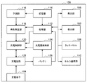
- FIG. 2 is a block diagram illustrating an example of the configuration of the information processing apparatus according to the embodiment of the present disclosure.
- FIG. 3 is a diagram illustrating an example of a conventional charging method.
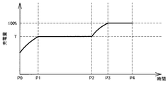
- FIG. 4 is a diagram illustrating an example of charge suppression control executed in the information processing apparatus according to the embodiment of the present disclosure.
- FIG. 5 is a diagram illustrating an example of the time when charging starts and the time when discharging starts in a mobile phone.
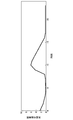
- FIG. 6 is a diagram illustrating an example of a chargeable time predicted in the information processing apparatus according to the embodiment of the present disclosure.
- FIG. 1 is a diagram illustrating an example of an appearance of an information processing apparatus according to an embodiment of the present disclosure.
- FIG. 2 is a block diagram illustrating an example of the configuration of the information processing apparatus according to the embodiment of the present disclosure.
- FIG. 3 is a diagram illustrating an example of
- FIG. 7 is a diagram illustrating an example of a process in which the estimated chargeable time is learned in the information processing apparatus according to the embodiment of the present disclosure.
- FIG. 8 is a diagram illustrating an example of a process in which the estimated chargeable time is learned in the information processing apparatus according to the embodiment of the present disclosure.
- FIG. 9 is a diagram illustrating an example of a process in which the estimated chargeable time is learned in the information processing apparatus according to the embodiment of the present disclosure.
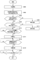
- FIG. 10 is a flowchart illustrating an example of charge suppression control executed in the information processing apparatus according to the embodiment of the present disclosure.
- FIG. 11 is a diagram illustrating an example of a display screen displayed in the information processing apparatus according to the embodiment of the present disclosure.
- FIG. 12 is a diagram illustrating another example of the charge suppression control executed in the information processing apparatus according to the embodiment of the present disclosure.
- FIG. 13 is a diagram illustrating an example of a display screen displayed in the information processing apparatus according to the embodiment of the present disclosure.
- FIG. 14 is a diagram illustrating an example of processing performed when the charge suppression control executed in the information processing apparatus according to the embodiment of the present disclosure is canceled.
- FIG. 15 is a diagram illustrating another example of the charge suppression control executed in the information processing apparatus according to the embodiment of the present disclosure.
- FIG. 16 is a flowchart illustrating another example of the charge suppression control process performed in the information processing apparatus according to the embodiment of the present disclosure.
- FIG. 17 is a flowchart illustrating another example of the charge suppression control process performed in the information processing apparatus according to the embodiment of the present disclosure.
- FIG. 18 is a diagram illustrating an example in which an information processing apparatus according to an embodiment of the present disclosure and another information processing apparatus are wirelessly connected.
- FIG. 19 is a diagram illustrating an example of a user activity amount calculated in another information processing apparatus according to the embodiment of the present disclosure.
- FIG. 1 is a diagram illustrating an appearance of a mobile phone 100 that is an example of an information processing apparatus according to an embodiment of the present disclosure.
- the mobile phone 100 according to the embodiment of the present disclosure includes a speaker and a microphone, and can communicate with other terminals by communicating with a base station included in the mobile communication network.
- the mobile phone 100 includes a display unit 102 that displays information, and a touch panel formed on the display unit 102. The user performs operations related to various functions or applications of the mobile phone 100 by operating using the touch panel.
- the mobile phone 100 also includes a charging terminal 104 to which a charger such as a USB (Universal Serial Bus) terminal is connected.
- a charger such as a USB (Universal Serial Bus) terminal
- the battery provided in the mobile phone 100 is charged by connecting a charger to the charging terminal 104.
- the charger is not limited to the USB terminal, and may be a charger specially prepared for the mobile phone 100.
- the mobile phone 100 includes a light emitting unit 106 that indicates the state of the mobile phone 100.
- the light emitting unit 106 emits light when the battery of the mobile phone 100 is charged, thereby indicating that the battery is charged.
- the information processing apparatus to which the charging control according to the present disclosure is applied is not limited to the mobile phone 100 as long as it is an apparatus that controls charging to a rechargeable battery.
- the information processing apparatus may be a personal computer including a rechargeable battery, a digital camera, or a wearable terminal.
- FIG. 2 is a block diagram showing the configuration of the mobile phone 100.
- a mobile phone 100 according to the present disclosure includes the display unit 102, the light emitting unit 106, and the touch panel 108 described above, and further includes a cellular communication unit 110.
- the display unit 102 displays information related to the function of the mobile phone 100 and the application executed on the mobile phone 100.
- the display unit 102 may be a liquid crystal display or an organic EL (Electro Luminescence) display.
- the touch panel 108 is used for the user to operate the functions and applications of the mobile phone 100.
- the touch panel 108 may be externally attached on the liquid crystal display or the organic EL display, or may be formed integrally with the liquid crystal display or the organic EL display.
- the light emitting unit 106 is used to indicate the state of the mobile phone 100.
- the light emitting unit 106 may emit light in different colors depending on the state of the mobile phone 100.
- the light emission part 106 may be formed using LED (Light Emitting Diode).
- the cellular communication unit 110 is used to communicate with other devices. For example, when the cellular communication unit 110 communicates with a base station of a mobile network, the mobile phone 100 is connected to a mobile phone network or the Internet. Note that the cellular communication unit 110 may be a wireless communication interface formulated in 3GPP such as LTE (Long Term Evolution).
- the mobile phone 100 includes a processing unit 112, a storage unit 114, a prediction unit 116, and a time specifying unit 118.
- the processing unit 112 is connected to each unit of the mobile phone 100 and executes various processes.
- the processing unit 112 executes functions and applications that the mobile phone 100 has.
- the functions and applications of the mobile phone 100 include, for example, mail, short message, social networking service, photography, music playback, browsing function, map display, alarm function, calendar function, and the like.
- the processing unit 112 generates information to be displayed on the display unit 102 and processes a signal from the touch panel 108.
- the storage unit 114 stores various data.
- the storage unit 114 stores, for example, information on an OS (Operating System) used in the mobile phone 100, data used by the prediction unit 116, information on an application executed on the mobile phone 100, and the like.
- the prediction unit 116 predicts a chargeable time from when the charger is connected to the mobile phone 100 to when the battery 126 starts discharging.
- the time specifying unit 118 specifies the time (timing) at which discharge from the battery 126 is started based on the chargeable time predicted by the prediction unit 116. A method for predicting the chargeable time will be described later.
- the mobile phone 100 includes a charge control unit 120, a charging circuit 122, a charge amount detection unit 124, and a battery 126.
- the charge control unit 120 controls the charging circuit 122 to perform charge suppression control, which will be described later, based on the discharge start time specified by the time specifying unit 118 and the charge amount of the battery 126 detected by the charge amount detection unit 124.
- the charge amount detection unit 124 may determine the charge amount of the battery 126 by detecting the voltage and current of the battery 126, and measure the charge amount of the battery 126 by measuring the current flowing into and out of the battery 126. May be determined.
- the charging circuit 122 switches the power feeding path based on the control from the charging control unit 120. That is, the charging circuit 122 charges the battery 126 by providing a power feeding path on the battery side under the control of the charging control unit 120, and stops charging the battery 126 by cutting the power feeding path to the battery 126. In addition, the charging circuit 122 supplies the power supplied from the charging terminal 104 to each unit of the mobile phone 100 without passing through the battery 126 by providing a power supply path on the charge control unit 120 side.
- FIG. 3 is a diagram illustrating a normal charging method compared with the charge suppression control of the present disclosure.
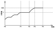
- charge suppression control as illustrated in FIG. 4 is executed.
- the charging suppression control in the present disclosure when a charger is connected to the charging terminal 104 of the mobile phone 100 at P0, the time when the charger is removed from the charging terminal 104 of the mobile phone 100 indicated by P4 is specified.
- the battery 126 is charged from the initial value to a predetermined charge amount represented by T (for example, 90% of full charge). Then, when the battery 126 is charged to the preparatory charge amount, charging to the battery 126 is stopped. At this time, the charging control unit 120 controls the charging circuit 122 so as to cut the power supply path to the battery 126. As a result, the power supplied from the charger is directly supplied to each part of the mobile phone 100 via the charging control unit 120.
- T for example, 90% of full charge
- the charge amount of the battery 126 is a predetermined charge threshold (threshold value) from the specified discharge start time to the time point P2 that is the time required for the charge amount to become fully charged from T and the time when the margin is subtracted. T). At time P2, charging of the battery 126 is resumed.
- the time required for the amount of charge to reach full charge from T and the time obtained by subtracting the margin may be calculated from a fixed value from the battery characteristics or from the battery history during use.
- the battery 126 When the charging of the battery 126 is resumed at P2, the battery 126 is fully charged at the point of P3.
- the time from P3 to P4 is a margin provided so that the battery 126 is reliably charged from the reserve charge amount to the full charge. This margin is provided to cope with a change in the time during which the battery 126 is charged from the preparation charge amount to the full charge depending on the state (temperature, etc.) of the mobile phone 100.
- the time for which the battery 126 is charged from the preparation charge amount to the full charge varies depending on the mode in which the battery 126 is charged.
- the mode for charging the battery 126 is, for example, rapid charging, and is a mode in which charging is performed gradually as the amount of charge of the battery 126 approaches 100%.
- charging suppression control is performed in which charging of the battery 126 is stopped at the preparatory charge amount and charging is resumed based on the specified discharge start time.
- the time during which the battery 126 is maintained in the overcharged state is shortened, and the battery 126 is fully charged when the user wants to use the information processing apparatus, so that a charging method that is highly convenient for the user is provided.
- the above-described charging suppression control whether or not there is a predetermined time or more from the point in time when charging is started (P0) to the time (P4) at which the charger is expected to be removed from the charging terminal 104. May be determined.
- the charge control as described above may be performed when the chargeable time predicted to be chargeable from P0 to P4 is a predetermined time or more.
- the above-described charging suppression control is not performed and normal charging is performed. As a result, it is possible to reduce the possibility that the battery 126 is not fully charged due to the suspension of charging. This chargeable time will be described in detail later.
- FIG. 5 is a diagram illustrating an example of a relationship between times when the user starts charging and using the mobile phone 100.
- the user starts charging at 10:00 on Monday and ends charging the mobile phone 100 at 16:00. That is, in FIG. 5, “charging start” means that the user has connected a charger to the charging terminal 104 of the mobile phone 100 for charging, and “discharge starting” means that the user uses the mobile phone 100. Therefore, it means that the charger is removed from the charging terminal 104 of the mobile phone 100.
- the predicting unit 116 can charge based on charging / discharging time information regarding the time when the charger is connected to the charging terminal 104 of the mobile phone 100 and the time when the charger is removed from the charging terminal 104 as shown in FIG. Predict time.
- the prediction unit 116 causes the storage unit 114 to store charge / discharge time information related to the charge start time and the discharge start time shown in FIG. Based on the stored charge / discharge time information, the prediction unit 116 predicts that the discharge from the battery 126 starts at 16:00 on Monday, and predicts the chargeable time based on this information. To do.
- the prediction unit 116 stores the charge / discharge time information in the storage unit 114 for one week or more for each day of the week, and predicts the chargeable time based on the charge / discharge time information of the corresponding day of the week.
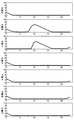
- FIG. 6 is a diagram illustrating an example of the chargeable time derived by the prediction unit 116.
- FIG. 6 shows how long charging is possible when charging of the mobile phone 100 is started at each “time” indicated by the horizontal axis.
- FIG. 6 shows the chargeable time derived by the prediction unit 116 when charging is started at around 10:00 and discharging is often started from the battery 126 at around 16:00.
- the predicting unit 116 predicts that the chargeable time is 6 hours.
- the chargeable time is shortened as the charging start time approaches 16:00 when discharging from the battery 126 is predicted.
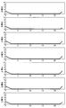
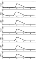
- FIGS. 7 to 9 are diagrams showing a process of learning the chargeable time shown in FIG.
- FIG. 7 is a diagram illustrating the state of each day of the week before starting learning.
- FIG. 8 is a diagram illustrating data related to the chargeable time after two days have elapsed since the prediction unit 116 started learning the chargeable time.
- FIG. 9 is a diagram illustrating data related to the chargeable time after one week has elapsed since the prediction unit 116 started learning the chargeable time. As can be seen from FIGS. 8 and 9, the prediction unit 116 derives a chargeable time for each day of the week.
- the storage unit 114 stores data related to the chargeable time as shown in FIG.
- the prediction unit 116 predicts how long charging is possible based on the time when the charger is connected to the mobile phone 100 and the data related to the chargeable time stored in the storage unit 114.
- the charge control part 120 may perform charge suppression control of this indication, when this chargeable time is more than predetermined time. By using the chargeable time in this way, it is avoided that the battery 126 is not sufficiently charged when the charge suppression control is performed because the chargeable time is too short.
- the prediction unit 116 may learn the chargeable time using the charge / discharge time information for two weeks. This is because the battery of recent years has a large capacity, and for example, it is considered that the user charges the battery 126 once every two days. That is, when the chargeable time is learned using the charge / discharge time information for one week, there are days (days of the week) when the charge / discharge time information cannot be obtained. In order to prevent this, for example, for the charge / discharge time information on the day when the charge / discharge time information is not obtained, the chargeable / discharge time information of the corresponding day of the previous week is used to learn the chargeable time. Good.
- the prediction unit 116 may learn the chargeable time using the charge / discharge time information for four weeks.
- the prediction unit 116 may derive the chargeable time by performing different weighting on the charge / discharge time information of different weeks. For example, the prediction unit 116 multiplies the charge / discharge time information of Tuesday four weeks ago by a coefficient 1, multiplies the charge / discharge time information of Tuesday three weeks ago by a coefficient 2, and adds a coefficient to the charge / discharge time information of Tuesday two weeks ago.
- the chargeable time may be derived by multiplying the charge / discharge time information of the last Tuesday by a coefficient of 4 and multiplying by 3.
- the prediction unit 116 may learn the chargeable time using information on holidays stored in the storage unit 114.
- the user's behavior often differs between a holiday and a weekday. For example, the user may wake up at different times on weekdays and holidays. Since it is preferable to use similar information in order to accurately predict the chargeable time, the prediction unit 116 learns the chargeable time on holidays using the charge / discharge time information on holidays and can be charged on weekdays. The time is learned using the charge / discharge time information on weekdays.
- whether or not it is a holiday may be determined based on information on a day of the week (for example, Saturday and Sunday) or a holiday that is set as a normal holiday in the calendar. Moreover, since a holiday changes with users, a user may be able to set a holiday. Moreover, since holidays, especially holidays, vary depending on the country, the prediction unit 116 may determine the country using the acquired position information, and learn the chargeable time using information related to holidays in that country. Thereby, the chargeable time according to the user's action on a holiday or the user's action on a weekday is accurately predicted.
- the prediction unit 116 predicts the chargeable time and sends the predicted chargeable time to the time specifying unit 118. Specifically, the prediction unit 116 predicts the chargeable time using the data related to the chargeable time described with reference to FIGS.
- the time specifying unit 118 receives the predicted chargeable time from the prediction unit 116, and specifies the discharge start time by adding the received chargeable time to the current time.
- the charge control unit 120 determines whether or not the chargeable time is a predetermined time or longer (for example, 4 hours or longer) based on the chargeable time predicted by the prediction unit 116.
- the charging control unit 120 controls the charging circuit 122 to perform normal charging (S108).
- the process proceeds to S106.
- the charge control unit 120 determines whether or not the charge amount of the battery 126 has reached the preparation charge amount.
- the charging control unit 120 controls the charging circuit 122 so as to temporarily stop the charging of the battery 126 in S110.
- the time specifying unit 118 determines whether or not the current time is a predetermined time before the discharge start time (for example, 90 minutes). If the time specifying unit 118 determines in S112 that the current time is a predetermined time before the predicted discharge start time, the charging control unit 120 controls the charging circuit 122 to resume charging of the battery 126 in S114.
- the charge control unit 120 determines whether or not the battery 126 is fully charged based on the charge amount of the battery 126 detected by the charge amount detection unit 124. If the charging control unit 120 determines in S116 that the battery 126 is fully charged, the charging control unit 120 controls the charging circuit 122 to stop charging the battery 126, and the process ends.
- the time specifying unit 118 may specify the time for recharging the battery 126 based on the state of the mobile phone 100.
- the state of the mobile phone 100 is a state based on a temperature measured by a temperature sensor of the mobile phone 100, for example.
- the time specifying unit 118 may specify the time at which charging of the battery 126 is resumed based on the charging mode of the mobile phone 100. This is performed in order to shorten the margin (time from P3 to P4 in FIG. 4) provided to ensure that the battery 126 is charged from the preparatory charge amount to full charge.
- the mode for charging the battery 126 is, for example, rapid charging, and is a mode in which charging is performed gradually as the amount of charge of the battery 126 approaches 100%. That is, the time for which the battery 126 is maintained in the overcharged state can be further shortened by changing the time at which the time specifying unit 118 resumes charging based on the state of the mobile phone 100 or the charging mode.
- the time specifying unit 118 increases the above-described margin.
- the time specifying unit 118 shortens the above-described margin.
- the storage unit 114 may store the time until the battery 126 is fully charged from the preparation charge amount and the temperature measured by the temperature sensor of the mobile phone 100 in association with each other. You may specify the time which restarts charge using this data. Accordingly, a margin suitable for the mobile phone 100 or the ambient temperature of the mobile phone 100 is set.
- the processing unit 112 may display a display indicating that the above-described charging suppression control is performed on the display unit 102.
- FIG. 11 is a diagram illustrating a charge mode display icon 130 indicating that charge suppression control is being performed.
- the charging mode display icon 130 may be displayed in the status bar 128 displayed on the display unit 102.
- a dialog indicating that charge suppression control is being performed may be displayed on the display unit 102.
- the fact that the above-described charge suppression control is being performed may be indicated using the light emitting unit 106.
- the light emitting unit 106 may change the color of the emitted light according to the currently executed charging mode. For example, when normal charging without performing the charge suppression control of the present disclosure is performed, the light emitting unit 106 may emit red light. In addition, when charging using the charging suppression control according to the present disclosure is performed, the light emitting unit 106 may emit green light. With this configuration, the user can easily check the charged mode even when the display unit 102 is not lit (for example, in a sleep state).
- the prediction of the chargeable time and the specification of the discharge start time are performed at the time when charging is started.
- the prediction of the chargeable time and the specification of the discharge start time may be performed when the charge amount of the battery 126 reaches the preparation charge amount. That is, normal charging is performed until the battery 126 reaches the preparation charge amount. Then, when the charge amount of the battery 126 reaches the preparatory charge amount, prediction of the chargeable time and identification of the discharge start time may be performed.
- FIG. 12 is a diagram illustrating another control example of the charge suppression control according to the present disclosure. Comparing FIG. 12 and FIG. 4, it can be seen that the process in which the battery 126 is charged from the initial value to the preparation charge amount (threshold value T) is different. That is, in FIG. 4, the battery 126 is continuously charged from the initial value to the preparation charge amount, while in FIG. 12, the battery 126 is charged stepwise from the initial value to the preparation charge amount.
- the charging method of the battery 126 from the initial value to the preparation charge amount may be a method of repeatedly stopping and restarting charging every predetermined time (for example, every hour). Further, the charging method of the battery 126 from the initial value to the preparatory charge amount may be a method of repeatedly stopping and restarting the charge every time the predetermined charge amount is reached.
- the charging control unit 120 may perform control so that charging is stopped every time the charging amount of the battery 126 increases by 10%, and charging is resumed after a predetermined time. That is, when the initial value of the charge amount of the battery 126 is 38%, the charge control unit 120 may temporarily stop the charge when the charge amount reaches 48%, 58%, and 68%.
- the charging control unit 120 may repeatedly stop and restart charging every time a predetermined amount of charge is charged. For example, the charging control unit 120 may perform control so that charging is stopped every time the battery 126 is charged 10% and charging is resumed after a predetermined time. That is, when the initial value of the charge amount of the battery 126 is 38%, the charge control unit 120 may temporarily stop the charge when the charge amount becomes 40%, 50%, or 60%.
- the battery 126 is charged in a stepwise manner from the initial value to the preparation charge amount, so that the battery 126 is maintained in a state where the charge amount is low for a longer time. In other words, a long period of time for which the battery 126 is maintained at a charge amount equal to or less than the preparatory charge amount that is the predetermined threshold T is secured. Thereby, deterioration of the battery 126 can be prevented more effectively.
- FIG. 13 is a diagram illustrating an example of a display screen used to cancel the charge suppression control of the present disclosure described above.
- the display similar to the charging mode display icon 130 demonstrated using FIG. 11 is displayed on the area
- the specified discharge start time is displayed in area 132. The user can cancel the charge suppression control by tapping the region 132 and can charge the battery 126 in the normal charging mode.
- FIG. 14 is a diagram illustrating charge control when the charge suppression control according to the present disclosure is canceled.
- FIG. 14 illustrates an example in which the user cancels the charge suppression control at the time point P5.
- the control when the charge suppression control is continuously performed by the solid line is shown, and the control when the charge suppression control is canceled by the dotted line is shown.
- the charge suppression control when the battery 126 is charged up to the preparatory charge amount, the charging is temporarily stopped at the time point P1.
- the charge amount of the battery 126 is maintained at the preparatory charge amount until the time point P5, and the charge suppression control is released at the time point P5.
- the charge suppression control is released, charging is resumed from the time of release (time P5), and the battery 126 is fully charged at time P6.
- the charging suppression control is canceled when the user shakes the mobile phone 100 at a predetermined acceleration or more. May be.
- the user can release the charge suppression control more quickly without operating the display content displayed on the display unit 102. This is very beneficial for users who have to deal with sudden schedule changes.
- a display for example, a message
- the light emitting unit 106 may emit light of a different color as described above to notify the user that the charge suppression control has been released.
- the user may be notified by voice that the charge suppression control has been released.
- the user may intentionally remove the charger from the mobile phone 100, or the user may unintentionally remove the charger from the mobile phone 100.
- the user intentionally removes the charger from the mobile phone 100 may be that the user activates an application of the mobile phone 100 in order to check a message from another person during charging.
- an example in which the charger is unintentionally removed from the mobile phone 100 by the user may be that the user accidentally drops the mobile phone 100 from the charger.
- FIG. 15 illustrates an example in which the charger is detached from the charging terminal 104 of the mobile phone 100 at the time point P7.
- the control when the charger is removed from the charging terminal 104 of the mobile phone 100 before the completion of the full charge during the charging suppression control with the dotted line is shown, and the control when the charger is not removed with the solid line Is shown.
- the charge suppression control The charging control unit 120 may be configured to return to step S2. By configuring the mobile phone 100 in this way, charge suppression control can be performed even if the charger is once removed.
- the battery 126 is charged from the time point P8 in FIG. 15 until the charge amount of the battery 126 reaches the preparatory charge amount (threshold value T), and at a predetermined time before the discharge start time first specified by the time specifying unit 118. Charging is stopped until a certain point P2. Also, at P8 when the charger is reconnected to the mobile phone 100, the prediction unit 116 predicts the chargeable time again, and the charge control unit 120 performs charge suppression control again based on the predicted chargeable time. May be.
- Charge suppression control using accuracy The processing when the charger is removed from the charging terminal 104 of the mobile phone 100 before the completion of full charging has been described above during the charging suppression control of the present disclosure. Hereinafter, the charge suppression control using the accuracy will be described.
- the accuracy is calculated, for example, by comparing the discharge start time specified by the time specifying unit 118 with the time when the user actually removed the charger from the mobile phone 100.
- the charge control unit 120 determines whether or not to perform the above-described charge suppression control using the accuracy of the discharge start time specified by the time specifying unit 118.
- the predicting unit 116 determines that the discharge start time specified by the time specifying unit 118 and the time when the user actually removed the charger from the mobile phone 100 are a predetermined time or longer (for example, 30 minutes or longer). It is determined whether or not there is a shift. When the discharge start time specified here and the time when the user actually removed the charger from the mobile phone 100 are different from each other by a predetermined time or more, it is determined that the prediction of the chargeable time is incorrect. Moreover, when the specified discharge start time and the time when the user actually removed the charger from the mobile phone 100 are within a predetermined time, it is determined that the prediction of the chargeable time is correct.
- the prediction unit 116 performs the above-described time comparison for one week, and the charge control unit 120 is configured to perform charge suppression control when the correct answer rate of the comparison becomes a predetermined value or more (for example, 80% or more). May be.
- FIG. 16 is a flowchart showing the operation of the charge suppression control using the accuracy.
- S200 to S204 correspond to S100 to S104 in FIG.
- the charging control unit 120 receives the accuracy from the prediction unit 116, and determines whether the accuracy is equal to or greater than a predetermined value. If the accuracy is equal to or higher than the predetermined value, the process proceeds to S210, and the charge control unit 120 performs the charge suppression control of the present disclosure. On the other hand, if it is determined in S206 that the accuracy is less than the predetermined value, the process proceeds to S212, and the charging control unit 120 performs normal charging. By configuring the information processing apparatus in this manner, charge suppression control is performed when a chargeable time having a certain accuracy is predicted.
- the application executed on the mobile phone 100 includes an application for which time or schedule is set.
- the application for which the time is set includes, for example, an application having a wake-up function, and an application having a calendar function for inputting a user's schedule.
- the time when the alarm function is set can be regarded as the time when the user starts using the mobile phone 100. That is, the time when the alarm function is set can be regarded as the time when the mobile phone 100 is detached from the charger and the battery 126 starts to be discharged.
- the calendar function when a specific schedule such as “going out” or “going home” is set, the start time of the specific schedule is also removed from the charger and the battery 126 is discharged. Can be considered to be the start time.
- the time specification unit 118 prioritizes the time at which the alarm function is set or the time at which a specific schedule is set over the discharge start time based on the chargeable time predicted by the prediction unit 116. It may be specified as a discharge start time for performing the charge suppression control.
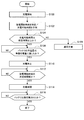
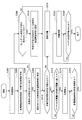
- FIG. 17 is a flowchart showing processing of charge suppression control using information from the application.
- charging is started by connecting a charger to the charging terminal 104 of the mobile phone 100.
- the prediction unit 116 predicts a chargeable time.
- the time specifying unit 118 receives the chargeable time predicted from the prediction unit 116 and specifies the discharge start time.
- the time specifying unit 118 determines whether or not there is a time set for executing the alarm function in the application having the alarm function.
- the process proceeds to S306.
- the time specifying unit 118 specifies the time set for executing the alarm function as the discharge start time.
- the charging control unit 120 determines whether or not the chargeable time is a predetermined time or more based on the discharge start time specified using the information from the application having an alarm function in S ⁇ b> 306.
- the process proceeds to S308.
- the time specifying unit 118 determines whether or not a specific schedule is set in the application having the calendar function.
- the process proceeds to S310.
- the time specifying unit 118 specifies the set start time of the specific schedule as the discharge start time.
- the charging control unit 120 determines whether or not the chargeable time is a predetermined time or more based on the discharge start time specified using the information from the application having the calendar function in S310.
- the process proceeds to S312.
- the charge control unit 120 determines whether or not the chargeable time is equal to or longer than a predetermined time based on the chargeable time predicted by the prediction unit 116 in S302. In the following process, the same process as the charge suppression control described in FIG. 10 is performed.
- the time set in the application is given priority over the discharge start time based on the chargeable time predicted by the prediction unit 116. It may be used as the start time.
- the charge suppression control according to the present disclosure is performed based on the time or schedule set by the user who seems to be more reliable.
- Charge suppression control based on information from other information processing devices >> The charging suppression control based on the application information for which a specific time or schedule is set has been described above. Below, the charge suppression control based on information from another information processing apparatus will be described.
- FIG. 18 is a diagram showing a wristband type small terminal 200 connected to the mobile phone 100 by short-range wireless communication.
- the small terminal 200 is connected to the mobile phone 100 using a short-range wireless communication interface such as Bluetooth (registered trademark).
- the small terminal 200 includes a sensor that detects the movement of the user to which the small terminal 200 is attached.
- the sensor that detects the movement of the user is, for example, an acceleration sensor or a gyro sensor.
- the small terminal 200 can also calculate the amount of activity of the user based on the information from the sensor that detects the movement of the user described above.
- FIG. 19 is a diagram illustrating an example of a user activity amount calculated by the small terminal 200. In the example shown in FIG. 19, the amount of activity of the user is large at around 7 o'clock, 12 o'clock and 18 o'clock.
- the amount of activity has increased around 7 o'clock due to the user getting up. Moreover, it is considered that the amount of activity increased around 12:00 because the user went out for lunch. In addition, it is considered that the amount of activity increased around 18:00 when the user came home.
- Such user actions such as getting up, going out, and returning home are actions that are closely related to the action of the user removing the mobile phone 100 from the charger.
- the prediction unit 116 may learn the chargeable time by using the above-described time when the user's activity amount calculated by the small terminal 200 becomes large instead of the time when discharging from the battery 126 is started. At this time, the calculated activity amount is stored in the mobile phone 100. Then, the prediction unit 116 learns the chargeable time by using the time when the activity amount becomes large as the time when the discharge from the battery 126 is started. Moreover, the prediction part 116 may learn chargeable time using the data of activity amount for one week or more similarly to the example mentioned above.
- charge suppression control is performed based on user behavior.
- the battery 126 is fully charged when the user performs an action that is expected to remove the charger from the mobile phone 100 while overcharging is suppressed.
- the chargeable time is predicted when the charging terminal 104 of the mobile phone 100 is connected to the charger (at time P0 in FIG. 4), and further when the battery 126 is charged to the preparatory charge amount (in FIG. 4). It may be predicted again at time P1). That is, the prediction unit 116 may predict the chargeable time multiple times. Accordingly, for example, the first user starts charging at a time when it is determined that the chargeable time is short (for example, 5 o'clock in FIG. 6), and it is determined that charging is continued and the chargeable time is equal to or longer than a predetermined time. The charging suppression control is performed when the operation is continued until the time (for example, 10:00 in FIG. 6).
- the prediction unit 116 predicted the chargeable time using data related to the chargeable time stored in the storage unit 114. However, the prediction unit 116 predicts the discharge start time instead of the chargeable time, and compares the time with the predicted discharge start time when the charger is connected to the charging terminal 104 of the mobile phone 100. May be used to predict the chargeable time. At this time, the time specifying unit 118 may specify the discharge start time using the discharge start time predicted by the prediction unit 116.
- an example in which an application having an alarm function and an application having a calendar function is used has been described.
- the application for which the time or schedule is set is not limited to these.
- the application having the alarm function is used to specify the discharge start time in preference to the application having the calendar function.
- the priority order of the application to be considered is not limited to the example described above.
- the priority of the application used for specifying the discharge start time may be set by the user.
- the mobile phone 100 may be configured to display a setting screen for setting the priority order of the application described above.
- a computer program for operating the prediction unit 116 and the charging control unit 120 as described above may be provided.
- a storage medium storing such a program may be provided.
- the charge suppression control is performed in which charging of the battery 126 is stopped at the preparatory charge amount and charging is resumed based on the specified discharge start time.
- the time during which the battery 126 is maintained in the overcharged state is shortened, and the battery 126 is fully charged when the user wants to use the information processing apparatus, so that a charging method that is highly convenient for the user is provided.
- the discharge start time is specified based on information from the application for which the time is set.
- the charge suppression control according to the present disclosure is performed based on the time set by the user who seems to be more reliable.
- the discharge start time is specified based on the activity amount of the user obtained from information of another information processing apparatus. Thereby, charge suppression control based on a user's action is performed.
- a charge amount detection unit for detecting the charge amount of the battery;
- a charge control unit for controlling the charging circuit;
- a specific unit that identifies when the battery starts to be discharged, and
- the charge control unit charges the battery to a preparatory charge amount less than a full charge amount of the battery based on the charge amount detected by the charge amount detection unit, Stop charging the battery when the amount of charge of the battery reaches the amount of reserve charge,
- An information processing apparatus that controls the charging circuit to perform charge suppression control in which charging of the battery is resumed from the preparatory charge amount before discharging of the battery is started.
- the specifying unit specifies a time at which discharging of the battery is started based on the chargeable time predicted by the prediction unit.
- the prediction unit derives the chargeable time based on the charge / discharge time information of one or more weeks.
- the information processing apparatus derives the chargeable time based on the charge / discharge time information of a corresponding day of the week in the one or more weeks.
- the prediction unit derives the chargeable time by performing different weighting on the charge / discharge time information of different weeks of the one or more weeks, according to (4) or (5), Information processing device.
- the charge control unit performs the charge suppression control when the chargeable time is equal to or longer than a predetermined time.
- the specifying unit changes a time at which charging is resumed from the preliminary charge amount based on a state of the information processing apparatus.
- the information processing apparatus controls the charging circuit so as to charge the battery in a stepwise manner up to the preliminary charge amount.
- the charging control unit controls the charging circuit to charge the battery every predetermined time when charging the battery up to the preparatory charge amount.
- the charging control unit controls the charging circuit to charge the battery for each predetermined charging amount when the battery is charged up to the preparation charging amount.
- a processing unit for executing the application The information processing apparatus according to any one of (1) to (12), wherein the specifying unit specifies a time at which discharging of the battery is started based on information from the application.
- the application is an application having an alarm function, The information processing apparatus according to (13), wherein the specifying unit specifies a time at which the alarm function is executed as a time at which the battery starts to be discharged.
- the application is an application having a calendar function, When a specific schedule is set in the application having the calendar function, the specifying unit specifies the time at which the specific schedule is set as the time at which the battery starts to be discharged (13) The information processing apparatus described in 1.
- the information processing apparatus further including a prediction unit that predicts a chargeable time based on information from another information processing apparatus.
- a prediction unit that predicts a chargeable time based on information from another information processing apparatus.
- the information from the other information processing apparatus is information based on a sensor that detects a movement of the other information processing apparatus included in the other information processing apparatus.
- a charge amount detection unit for detecting the charge amount of the battery; A charge control unit for controlling the charging circuit; A time specifying unit for specifying when the discharge of the battery is started, and The charge control unit charges the battery to a preparatory charge amount less than a full charge amount of the battery based on the charge amount detected by the charge amount detection unit, Stop charging the battery when the amount of charge of the battery reaches the amount of reserve charge, An information processing system for controlling the charging circuit to perform charge suppression control for restarting charging of the battery from the preparatory charge amount before discharging of the battery is started.
Landscapes
- Engineering & Computer Science (AREA)
- Power Engineering (AREA)
- Manufacturing & Machinery (AREA)
- Chemical & Material Sciences (AREA)
- Chemical Kinetics & Catalysis (AREA)
- Electrochemistry (AREA)
- General Chemical & Material Sciences (AREA)
- Theoretical Computer Science (AREA)
- Evolutionary Computation (AREA)
- Data Mining & Analysis (AREA)
- Computational Linguistics (AREA)
- Physics & Mathematics (AREA)
- Computing Systems (AREA)
- General Engineering & Computer Science (AREA)
- General Physics & Mathematics (AREA)
- Mathematical Physics (AREA)
- Software Systems (AREA)
- Artificial Intelligence (AREA)
- Charge And Discharge Circuits For Batteries Or The Like (AREA)
- Telephone Function (AREA)
Priority Applications (5)
| Application Number | Priority Date | Filing Date | Title |
|---|---|---|---|
| JP2018527393A JP6926081B2 (ja) | 2016-07-13 | 2017-04-03 | 情報処理装置、情報処理システム、充電方法 |
| CN202310354944.8A CN116470609A (zh) | 2016-07-13 | 2017-04-03 | 信息处理装置和充电方法 |
| EP17827189.6A EP3484010A4 (de) | 2016-07-13 | 2017-04-03 | Informationsverarbeitungsvorrichtung, informationsverarbeitungssystem und ladeverfahren |
| US16/314,667 US11336107B2 (en) | 2016-07-13 | 2017-04-03 | Information processing device, information processing system, and charging method |
| CN201780041764.7A CN109417300B (zh) | 2016-07-13 | 2017-04-03 | 信息处理装置和充电方法 |
Applications Claiming Priority (2)
| Application Number | Priority Date | Filing Date | Title |
|---|---|---|---|
| JP2016138673 | 2016-07-13 | ||
| JP2016-138673 | 2016-07-13 |
Publications (1)
| Publication Number | Publication Date |
|---|---|
| WO2018012055A1 true WO2018012055A1 (ja) | 2018-01-18 |
Family
ID=60952013
Family Applications (1)
| Application Number | Title | Priority Date | Filing Date |
|---|---|---|---|
| PCT/JP2017/013969 WO2018012055A1 (ja) | 2016-07-13 | 2017-04-03 | 情報処理装置、情報処理システム、充電方法 |
Country Status (5)
| Country | Link |
|---|---|
| US (1) | US11336107B2 (de) |
| EP (1) | EP3484010A4 (de) |
| JP (1) | JP6926081B2 (de) |
| CN (2) | CN109417300B (de) |
| WO (1) | WO2018012055A1 (de) |
Cited By (1)
| Publication number | Priority date | Publication date | Assignee | Title |
|---|---|---|---|---|
| EP3518380A1 (de) * | 2018-01-25 | 2019-07-31 | Samsung Electronics Co., Ltd. | Elektronische vorrichtung mit batterie und verfahren zur steuerung der aufladung derselben |
Families Citing this family (9)
| Publication number | Priority date | Publication date | Assignee | Title |
|---|---|---|---|---|
| CN107681713B (zh) * | 2017-09-13 | 2021-10-22 | 惠州Tcl移动通信有限公司 | 一种多模式充电控制方法、移动终端及存储介质 |
| US11862772B2 (en) * | 2018-03-29 | 2024-01-02 | Canal Electronics LLC | User-defined battery recharging systems and methods |
| US20220247196A1 (en) * | 2019-07-22 | 2022-08-04 | Hewlett-Packard Development Company, L.P. | Schedule-based charging of batteries |
| CN111564877A (zh) * | 2020-04-30 | 2020-08-21 | 华为技术有限公司 | 用于充电管控的方法和装置 |
| CN113839427A (zh) * | 2020-06-05 | 2021-12-24 | 华为技术有限公司 | 一种充电管理方法、电子设备和系统 |
| WO2022081190A1 (en) * | 2020-10-13 | 2022-04-21 | Google Llc | Charging electronic device up to derated maximum charging level |
| CA3217299A1 (en) * | 2021-05-04 | 2022-11-10 | Tung Nguyen | Battery control systems and methods |
| CA3159864A1 (en) | 2021-05-13 | 2022-11-13 | Exro Technologies Inc. | Method and apparatus to drive coils of a multiphase electric machine |
| CN113659655B (zh) * | 2021-07-26 | 2024-05-10 | 珠海格力电器股份有限公司 | 电子设备的充电方法、装置、电子设备和存储介质 |
Citations (8)
| Publication number | Priority date | Publication date | Assignee | Title |
|---|---|---|---|---|
| JP2002142378A (ja) * | 2000-10-31 | 2002-05-17 | Canon Inc | 充電装置、方法及び記憶媒体 |
| JP2004236426A (ja) | 2003-01-30 | 2004-08-19 | Fujitsu Support & Service Kk | バッテリー充放電制御装置 |
| WO2012093638A1 (ja) * | 2011-01-06 | 2012-07-12 | 日本電気株式会社 | 充電制御装置、充電制御方法、及びプログラム |
| JP2013031232A (ja) * | 2009-11-16 | 2013-02-07 | Sanyo Electric Co Ltd | 充電装置及び充電方法 |
| JP2014176104A (ja) * | 2013-03-05 | 2014-09-22 | Funai Electric Co Ltd | 機器および充電制御方法 |
| JP2014176260A (ja) * | 2013-03-12 | 2014-09-22 | Sharp Corp | 充電システムおよび自走式機器 |
| JP2015104139A (ja) * | 2013-11-20 | 2015-06-04 | 株式会社Wave Technology | 二次電池の充電方法およびそれを用いた充電装置 |
| WO2016052100A1 (ja) * | 2014-09-29 | 2016-04-07 | シャープ株式会社 | 情報処理装置、情報処理装置の制御方法、および制御プログラム |
Family Cites Families (22)
| Publication number | Priority date | Publication date | Assignee | Title |
|---|---|---|---|---|
| CN1076889C (zh) * | 1994-08-09 | 2001-12-26 | 日本电池株式会社 | 制备镍-氢电池的方法 |
| JPH09168240A (ja) * | 1995-12-12 | 1997-06-24 | Toyota Motor Corp | バッテリ充電装置 |
| JP2005027435A (ja) * | 2003-07-02 | 2005-01-27 | Sony Corp | 充電装置 |
| US7446509B2 (en) * | 2004-05-08 | 2008-11-04 | Gem Power, Llc | Intelligent battery charging system |
| US20060226807A1 (en) * | 2005-03-30 | 2006-10-12 | Simpson Russell L | Method and apparatus for maximizing battery charge |
| US7991513B2 (en) * | 2007-05-08 | 2011-08-02 | Ecodog, Inc. | Electric energy bill reduction in dynamic pricing environments |
| US7782021B2 (en) * | 2007-07-18 | 2010-08-24 | Tesla Motors, Inc. | Battery charging based on cost and life |
| WO2009047918A1 (ja) * | 2007-10-11 | 2009-04-16 | Panasonic Corporation | 高電圧発生回路、穿刺装置及び血液検査装置 |
| US20090289603A1 (en) * | 2008-05-21 | 2009-11-26 | Apple Inc. | Method and apparatus for maintaining a battery in a partially charged state |
| JP4932810B2 (ja) * | 2008-10-20 | 2012-05-16 | マツダ株式会社 | 電動車両用バッテリの充電方法およびその装置 |
| US20100123436A1 (en) * | 2008-11-14 | 2010-05-20 | Symbol Technologies, Inc. | Optimized lithium-ion battery charging |
| US8922329B2 (en) * | 2009-07-23 | 2014-12-30 | Qualcomm Incorporated | Battery charging to extend battery life and improve efficiency |
| CN102549875B (zh) * | 2009-08-11 | 2014-10-22 | 索尼公司 | 电子设备、对电子设备充电的方法、程序、充电控制装置以及充电控制方法 |
| JP2011151891A (ja) * | 2010-01-19 | 2011-08-04 | Sony Corp | 二次電池の充電方法および充電装置 |
| US8638070B2 (en) * | 2010-05-21 | 2014-01-28 | Qnovo Inc. | Method and circuitry to adaptively charge a battery/cell |
| JP5982736B2 (ja) * | 2011-03-30 | 2016-08-31 | ソニー株式会社 | 蓄電装置、蓄電方法およびプログラム |
| JP5516550B2 (ja) * | 2011-05-09 | 2014-06-11 | 株式会社デンソー | 車両用ナビゲーション装置 |
| JP5919506B2 (ja) * | 2011-09-20 | 2016-05-18 | パナソニックIpマネジメント株式会社 | 充電式電気機器 |
| US20140099614A1 (en) * | 2012-10-08 | 2014-04-10 | Lark Technologies, Inc. | Method for delivering behavior change directives to a user |
| WO2015056312A1 (ja) * | 2013-10-16 | 2015-04-23 | 一般財団法人日本自動車研究所 | リチウムイオン電池の劣化推定装置及び劣化推定方法 |
| US20160380440A1 (en) * | 2015-06-26 | 2016-12-29 | TEQ Charging, Inc. | Electric charging power management |
| US10250052B2 (en) * | 2015-12-03 | 2019-04-02 | Qualcomm Incorporated | Charge rate optimization for enhanced battery cycle life |
-
2017
- 2017-04-03 US US16/314,667 patent/US11336107B2/en active Active
- 2017-04-03 JP JP2018527393A patent/JP6926081B2/ja active Active
- 2017-04-03 CN CN201780041764.7A patent/CN109417300B/zh active Active
- 2017-04-03 CN CN202310354944.8A patent/CN116470609A/zh active Pending
- 2017-04-03 EP EP17827189.6A patent/EP3484010A4/de active Pending
- 2017-04-03 WO PCT/JP2017/013969 patent/WO2018012055A1/ja unknown
Patent Citations (8)
| Publication number | Priority date | Publication date | Assignee | Title |
|---|---|---|---|---|
| JP2002142378A (ja) * | 2000-10-31 | 2002-05-17 | Canon Inc | 充電装置、方法及び記憶媒体 |
| JP2004236426A (ja) | 2003-01-30 | 2004-08-19 | Fujitsu Support & Service Kk | バッテリー充放電制御装置 |
| JP2013031232A (ja) * | 2009-11-16 | 2013-02-07 | Sanyo Electric Co Ltd | 充電装置及び充電方法 |
| WO2012093638A1 (ja) * | 2011-01-06 | 2012-07-12 | 日本電気株式会社 | 充電制御装置、充電制御方法、及びプログラム |
| JP2014176104A (ja) * | 2013-03-05 | 2014-09-22 | Funai Electric Co Ltd | 機器および充電制御方法 |
| JP2014176260A (ja) * | 2013-03-12 | 2014-09-22 | Sharp Corp | 充電システムおよび自走式機器 |
| JP2015104139A (ja) * | 2013-11-20 | 2015-06-04 | 株式会社Wave Technology | 二次電池の充電方法およびそれを用いた充電装置 |
| WO2016052100A1 (ja) * | 2014-09-29 | 2016-04-07 | シャープ株式会社 | 情報処理装置、情報処理装置の制御方法、および制御プログラム |
Cited By (6)
| Publication number | Priority date | Publication date | Assignee | Title |
|---|---|---|---|---|
| EP3518380A1 (de) * | 2018-01-25 | 2019-07-31 | Samsung Electronics Co., Ltd. | Elektronische vorrichtung mit batterie und verfahren zur steuerung der aufladung derselben |
| KR20190090474A (ko) * | 2018-01-25 | 2019-08-02 | 삼성전자주식회사 | 배터리를 포함하는 전자 장치 및 이의 충전구간을 제어하는 방법 |
| CN111433999A (zh) * | 2018-01-25 | 2020-07-17 | 三星电子株式会社 | 包括电池的电子装置及控制其充电的方法 |
| US11056903B2 (en) | 2018-01-25 | 2021-07-06 | Samsung Electronics Co., Ltd. | Electronic device including battery and method of controlling charging thereof |
| EP3972076A1 (de) * | 2018-01-25 | 2022-03-23 | Samsung Electronics Co., Ltd. | Elektronische vorrichtung mit batterie und verfahren zur steuerung ihrer aufladung |
| KR102544462B1 (ko) * | 2018-01-25 | 2023-06-19 | 삼성전자 주식회사 | 배터리를 포함하는 전자 장치 및 이의 충전구간을 제어하는 방법 |
Also Published As
| Publication number | Publication date |
|---|---|
| JP6926081B2 (ja) | 2021-08-25 |
| EP3484010A1 (de) | 2019-05-15 |
| EP3484010A4 (de) | 2020-01-08 |
| US20190334354A1 (en) | 2019-10-31 |
| CN116470609A (zh) | 2023-07-21 |
| US11336107B2 (en) | 2022-05-17 |
| CN109417300B (zh) | 2023-04-28 |
| CN109417300A (zh) | 2019-03-01 |
| JPWO2018012055A1 (ja) | 2019-04-25 |
Similar Documents
| Publication | Publication Date | Title |
|---|---|---|
| WO2018012055A1 (ja) | 情報処理装置、情報処理システム、充電方法 | |
| EP3574546B1 (de) | Steuerungsverfahren und elektronische vorrichtung auf basis eines batterieleckzustands | |
| US20190069244A1 (en) | Electronic device for providing mode switching and a method thereof | |
| US7548767B2 (en) | Low power warning in a portable communication device based on predicted device utilization | |
| US20150123595A1 (en) | Intelligent context based battery charging | |
| US9350188B2 (en) | Electronic device and power-source device | |
| US9391466B2 (en) | Method and device for battery-charging management | |
| EP2416243A1 (de) | Einrichtung zum aktualisieren von software, die in einem fahrzeug angebracht ist | |
| US11122510B2 (en) | Power and notification management for a wearable device | |
| JP5555533B2 (ja) | 制御装置、端末装置及びプログラム | |
| WO2013112599A1 (en) | Power management for electronic devices | |
| US20130119942A1 (en) | Method and system for determining a charge rate for a rechargeable battery | |
| EP2595269A1 (de) | Verfahren und System zur Bestimmung einer Laderate für wiederaufladbare Batterien | |
| CN109471516B (zh) | 一种终端及其耗电控制方法、装置、计算机可读存储介质 | |
| CN114977343A (zh) | 一种充电方法、装置、电子设备及存储介质 | |
| KR20160055906A (ko) | 컨텍스트 전력 관리 | |
| US11177674B2 (en) | Communication apparatus with charging reminder, and method | |
| KR20060042644A (ko) | 이동 통신 단말기의 알람 서비스 제어 방법 | |
| JP4990612B2 (ja) | 充電制御装置、携帯端末装置、および充電制御方法 | |
| US11397456B2 (en) | Selective notification based on charge history | |
| JP2011062028A (ja) | 充電可能な装置及びその充電方法 | |
| EP2880707A1 (de) | Verfahren und vorrichtung zur batterieladungsverwaltung | |
| US20210088593A1 (en) | Charging reminding method for rechargeable device and memory | |
| US20180375344A1 (en) | Situational battery charging | |
| JP6523073B2 (ja) | 電源管理システム |
Legal Events
| Date | Code | Title | Description |
|---|---|---|---|
| ENP | Entry into the national phase |
Ref document number: 2018527393 Country of ref document: JP Kind code of ref document: A |
|
| 121 | Ep: the epo has been informed by wipo that ep was designated in this application |
Ref document number: 17827189 Country of ref document: EP Kind code of ref document: A1 |
|
| NENP | Non-entry into the national phase |
Ref country code: DE |
|
| ENP | Entry into the national phase |
Ref document number: 2017827189 Country of ref document: EP Effective date: 20190206 |