WO2018011982A1 - プレス装置及びロータリープレス盤 - Google Patents
プレス装置及びロータリープレス盤 Download PDFInfo
- Publication number
- WO2018011982A1 WO2018011982A1 PCT/JP2016/071017 JP2016071017W WO2018011982A1 WO 2018011982 A1 WO2018011982 A1 WO 2018011982A1 JP 2016071017 W JP2016071017 W JP 2016071017W WO 2018011982 A1 WO2018011982 A1 WO 2018011982A1
- Authority
- WO
- WIPO (PCT)
- Prior art keywords
- press
- wheel
- contact portion
- head
- central axis
- Prior art date
- Legal status (The legal status is an assumption and is not a legal conclusion. Google has not performed a legal analysis and makes no representation as to the accuracy of the status listed.)
- Ceased
Links
Images





Classifications
-
- B—PERFORMING OPERATIONS; TRANSPORTING
- B30—PRESSES
- B30B—PRESSES IN GENERAL
- B30B11/00—Presses specially adapted for forming shaped articles from material in particulate or plastic state, e.g. briquetting presses, tabletting presses
-
- B—PERFORMING OPERATIONS; TRANSPORTING
- B30—PRESSES
- B30B—PRESSES IN GENERAL
- B30B13/00—Methods of pressing not special to the use of presses of any one of the preceding main groups
Definitions
- the present invention relates to a press device that presses a powder sandwiched between an upper plate and a lower plate through the upper plate and the lower plate, and also relates to a rotary press machine used in the press device.
- Patent Document 1 discloses a powder compression molding apparatus (A) that solidifies by compressing powder using a mortar (4), an upper punch (5), and a lower punch (6).
- a powder compression molding apparatus A
- a plurality of upper collars (5) are attached to the outer peripheral portion of the upper part (31) of the turntable (3) so as to be arranged at equal intervals in the circumferential direction. Are provided so that they can be raised and lowered individually.
- a plurality of lower cages (6) that can be raised and lowered are attached to the lower part (32) of the turntable (3) so as to be arranged at equal intervals in the circumferential direction.
- the mortar (4) is attached to the intermediate portion (33) in the height direction of the rotating disk (3) so as to be arranged at equal intervals in the circumferential direction.
- a powder supply device (7) and a pair of upper and lower pressure rolls (84, 85) are arranged. During the rotation of the rotating disk (3), when the die (3) passes through the powder supply device (7), the powder is supplied to the die (3) by the powder supply device (7).
- These pressure rolls (84, 85) are rotatably provided around their respective horizontal central axes, and the intervals between the pressure rolls (84, 85) are kept constant.
- the upper collar (5) is pressed against the upper pressure roll (84)
- the lower collar (6) is pressed against the lower pressure roll (85)
- these pressure rolls (84, 85) are It rotates following the movement of heel (5) and lower heel (6).
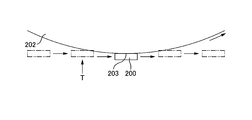
- FIG. 13 shows the movement of the head of the upper collar and the upper pressure roll when the upper collar and the lower collar pass between the pair of pressure rolls.
- the upper eyelid 200 moves from the left to the right in the figure, and the pressure roll 202 rotates counterclockwise in the figure.
- the upper collar 200 contacts a position of the outer circumferential surface of the pressure roll 202 that is displaced from the lowermost portion 203.
- the pressure roll 202 rotates following the movement of the upper eyelid 200.
- the problem to be solved by the present invention is to prevent lateral loads from being applied to the bag.
- a press device that sequentially presses a plurality of upper eyelids sequentially passing a predetermined press position and a plurality of lower eyelids on the lower side of the upper eyelid at the press position is an upper side of the press position.
- a lower wheel that is rotatably provided below the press position, and a plurality of lower wheels that are attached to the lower wheel so as to be arranged along a circumferential direction of the lower wheel and press-contact with a lower end head portion of the lower collar A lower pressure contact portion.
- a press device that sequentially presses a plurality of upper eyelids that sequentially pass a predetermined press position and a plurality of lower eyelids on the lower side of the upper eyelid at the press position, an upper provided rotatably above the press position A wheel, a plurality of upper pressure contact portions that are attached to the upper wheel so as to be arranged along a circumferential direction of the upper wheel, and that are pressed against the head of the upper end of the upper collar, and rotate at a lower side of the press position A lower wheel provided in a possible manner, and a plurality of lower press-contact portions that are attached to the lower wheel so as to be arranged along a circumferential direction of the lower wheel and press-contact with a lower end head portion of the lower collar.
- a rotary press machine comprising a rotatable wheel and a press contact portion that is attached to the wheel at a position shifted from the central axis of the wheel and presses against the head of the scissors that strikes the powder with a scissors tip becomes clear.
- the press apparatus and the rotary press panel as described above, when the upper wheel and the lower wheel rotate, the upper press contact portion and the lower press contact portion turn, and the upper press contact portion and the lower press contact portion draw a circular locus. Therefore, immediately before the upper arm passes the press position and the upper pressure contact portion passes the lowermost part, the upper pressure contact portion approaches the head portion of the upper eyelid downward and in accordance with the movement of the head portion of the upper eyelid. Move horizontally. For this reason, the upper pressure contact portion comes into contact with the upper head portion from directly above the upper head portion. Therefore, a lateral load is not applied to the upper eyelid. Similarly, since the lower pressure contact portion comes into contact with the head of the lower eyelid from directly under the head of the lower eyelid, a lateral load is not applied to the lower eyelid.
- the upper press contact portion is attached to the upper wheel so as to be rotatable about an axis parallel to the central axis of the upper wheel
- the lower press contact portion is attached to the central axis of the lower wheel. It is attached to the lower wheel so as to be rotatable about a parallel axis.
- the upper press contact portion has an outer peripheral surface formed in a cylindrical surface shape around its axis
- the lower press contact portion has an outer peripheral surface formed in a cylindrical surface shape around its axis.
- the press contact portion is attached to the wheel so as to be rotatable around an axis parallel to a central axis of the wheel. More preferably, the press contact portion has an outer peripheral surface formed in a cylindrical surface around its axis.
- the upper press contact portion and the upper punch head are rotated by the rotation of the upper press contact portion pressed against the upper punch head when the upper punch passes the press position. No slip occurs between the parts. Therefore, the load in the direction in which the upper eyelid falls is not applied to the upper eyelid. The same applies to the lower collar and the lower press-contact portion.
- the press device further includes an upper elastic member and a lower elastic member, and the upper pressure contact portion is attached to the upper wheel so as to be movable in a direction parallel to a central axis of the upper wheel.
- An elastic member holds the upper press-contact portion against movement of the upper press-contact portion, and the lower press-contact portion is movable in a direction parallel to the central axis of the lower wheel and is attached to the lower wheel.
- the lower elastic member holds the lower press-contact portion against movement of the lower press-contact portion.
- the press device when the trajectory when the upper eyelid and the lower eyelid pass through the press position is a curve, the upper pressure contact portion pressed against the head portion of the upper eyelid moves in the axial direction, No slip occurs between the upper pressure contact part and the upper head. Therefore, the load in the direction in which the upper eyelid falls is not applied to the upper eyelid. The same applies to the lower collar and the lower press-contact portion. Further, after the upper pressure contact portion moves in the axial direction, the upper pressure contact portion returns to the original position by the elastic force of the upper elastic member. The same applies to the lower pressure contact portion.
- a peripheral pitch between the upper press contact portions is equal to an interval between the upper punches, and a peripheral pitch between the lower press contact portions is an interval between the lower presses. equal.
- the upper pressure contact portion comes into contact with the head portion of the upper collar from directly above the head portion of the upper collar, and the movement of the upper pressure contact section can be adjusted to the movement of the upper collar.
- the lower pressure contact portion comes into contact with the head portion of the lower eyelid from directly below the head portion of the lower eyelid, and the movement of the lower eyelid pressure contact portion can be adjusted to the movement of the upper eyelid. For this reason, it is possible to more efficiently suppress the generation of a load in the direction in which the upper and lower eyelids fall.
- the press device further includes a rotary driving machine that rotationally drives the upper wheel and the lower wheel. More preferably, the rotary drive rotates the upper wheel so that the upper press contact portion passes through the press position in synchronization with the timing when the upper guide passes through the press position, and the lower guide Synchronously with the timing of passing through the press position, the rotary drive rotates the lower wheel so that the lower pressure contact portion passes through the press position.
- a rotary driving machine that rotationally drives the upper wheel and the lower wheel. More preferably, the rotary drive rotates the upper wheel so that the upper press contact portion passes through the press position in synchronization with the timing when the upper guide passes through the press position, and the lower guide Synchronously with the timing of passing through the press position, the rotary drive rotates the lower wheel so that the lower pressure contact portion passes through the press position.
- the rotary drive unit drives the upper wheel to rotate so that the peripheral speed of the upper pressure contact portion around the central axis of the upper wheel is equal to the moving speed of the upper rod, and the center of the lower wheel
- the rotary drive rotates the lower wheel so that the peripheral speed of the lower pressure contact portion around the axis is equal to the moving speed of the lower rod.
- the upper pressure contact portion comes into contact with the head portion of the upper collar from directly above the head portion of the upper collar, and the movement of the upper pressure contact section can be adjusted to the movement of the upper collar.
- the lower pressure contact portion comes into contact with the head portion of the lower eyelid from directly below the head portion of the lower eyelid, and the movement of the lower pressure contact portion can be adjusted to the movement of the lower eyelid. For this reason, it is possible to more efficiently suppress the generation of a load in the direction in which the upper and lower eyelids fall.
- the press device further includes a pressurizer that applies a load in a direction in which the upper wheel and the lower wheel approach each other to at least one of the upper wheel and the lower wheel. More preferably, the pressurizer applies a constant load to at least one of the upper wheel and the lower wheel.
- an appropriate pressure can be applied to the powder, and the powder can be solidified satisfactorily.
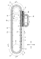
- FIG. 1 is a perspective view of a compression molding apparatus 1.
- FIG. 2 is a plan view of the compression molding apparatus 1.
- FIG. 3 is a perspective view of the tableting machine row 20.
- the compression molding apparatus 1 includes a travel guide 10, a tableting machine row 20, a tableting operation cam 70, a travel drive apparatus 80, a powder supply apparatus 90, a rotary press apparatus 100, and the like. Prepare.
- the travel guide 10 is a closed route.
- the travel guide 10 includes an upper rail 11 and a lower rail 12 that are formed in an oval shape as a closed curve.
- the upper rail 11 and the lower rail 12 are provided in parallel with each other in a horizontal manner with a vertical interval therebetween.
- the oval shape refers to an ellipse or a shape similar thereto, and in addition to an ellipse, an oval, a rounded rectangle, and an oval are a kind of oval.
- a rounded rectangle is one in which corners of a rectangle are formed in an arc shape.
- the upper rail 11 has a rounded rectangular shape, in particular, an entire short side portion having an arc shape.
- the upper rail 11 has two straight portions 11a and 11b that are equal in length and parallel to each other, and one semicircular arc portion 11c connected between one ends of the straight portions 11a and 11b. And the other semicircular arc portion 11d connected between the other ends of the straight portions 11a and 11b.
- the lower rail 12 is the same as the upper rail 11.
- the tableting machine row 20 has a plurality of tableting machines 21 that are modularized. These tableting machines 21 are arranged at equal intervals along the travel guide 10 to form a tableting machine row 20. These tableting machines 21 are arranged over the entire circumference of the travel guide 10, but in order to make the travel guide 10 and the tableting operation cam 70 easier to see in FIGS. 1 and 2, some tableting machines 21. Is illustrated. In FIG. 2, the illustration of the traveling drive device 80 is omitted.
- these tableting machines 21 are supported by the travel guide 10 and guided along the travel guide 10.
- the travel drive device 80 applies power to the tableting machine 21 to cause the tableting machine 21 to travel in a counterclockwise direction (see arrow A in FIG. 2) when viewed from above. Thereby, the tableting machine 21 is circulated along the traveling guide 10.
- the tableting operation cam 70 causes the tableting machine 21 to perform a tableting operation as the tableting machine 21 travels.
- the powder supply device 90 provided at a predetermined position on the travel path of the tableting machine 21 (especially the side of the straight portion 11b of the upper rail 11) is used to pulverize the powder into a plurality of tableting machines 21 (particularly, a die 30 described later). Are sequentially supplied to the mortar 31).
- the rotary press device 100 provided at a predetermined position on the travel path of the tableting machine 21 (particularly the side of the straight portion 11b of the upper rail 11) presses the powder struck by the tableting machine 21 to produce powder. To solidify. Tablets are formed from the compressed powder. Since the plurality of tablet presses 21 sequentially pass through the press device 100, the powder supplied to the tablet press 21 is sequentially pressed by the press device 100.
- a plurality of powder supply devices 90 may be provided, and these powder supply devices 90 may be arranged along the straight portions 11 b of the upper rail 11, and these powder supply devices 90 may supply different powders to the tableting machine 21.
- the small piece transfer device is arranged in parallel with the powder supply device 90, and small pieces (for example, electronic components such as IC chips, active elements, passive elements, and solid agents) supplied to the small piece transfer device are driven by the small piece transfer device. It may be transferred to the lock machine 21 (particularly, the mortar 31 of the mortar 30 described later).
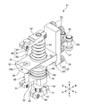
- FIG. 4 is a perspective view showing the tableting machine 21 as viewed from the front side, the upper side, and the right side.
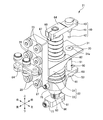
- FIG. 5 is a perspective view showing the tableting machine 21 as viewed from the rear side, the upper side, and the left side.
- FIG. 6 is a right side view of the tableting machine 21.
- FIG. 7 is a plan view of the tableting machine 21.
- FIG. 8 is a cross-sectional view showing a part of the tableting machine 21 cut along the line VIII-VIII shown in FIG.
- the front surface of the tableting machine 21 refers to the surface facing the outside of the travel guide 10
- the rear surface of the tableting machine 21 refers to the surface facing the inside of the travel guide 10.
- the tableting machine 21 includes a traveling carriage 22, a die 30, an upper punch 40, a lower punch 50, a linear motion guide mechanism 60, brackets 64 to 66, cam followers 77 and 78, and the like.
- the traveling carriage 22 is provided in a horizontal T shape when viewed from the left side or the right side. That is, the traveling carriage 22 has a rectangular plate-shaped roller support plate 23 and a holding plate 24, and the roller support plate 23 is supported by the traveling guide 10 in a standing state, and the holding plate 24 is placed on the front surface of the roller support plate 23. Extends forward from the middle in the height direction.
- traveling rollers 25 to 28 are rotatably provided on the rear surface of the roller support plate 23.
- the rotation shafts of the traveling rollers 25 to 28 extend rearward from the rear surface of the roller support plate 23.
- These travel rollers 25 to 28 are provided in four upper and lower stages.
- the roller support plate 23 is disposed outside the rails 11 and 12 (see FIGS. 1, 2, and 6), and the holding plate 24 extends outward from the rails 11 and 12.
- the traveling roller 22 and the traveling roller 26 sandwich the upper rail 11 between them, so that the traveling carriage 22 is supported by the upper rail 11.
- the traveling carriage 22 is supported on the lower rail 12 by the traveling rollers 27 and 28.
- the traveling rollers 25 and 26 roll with respect to the upper rail 11, and the traveling rollers 27 and 28 roll with respect to the lower rail 12, whereby the traveling carriage 22 extends along the rails 11 and 12 outside the rails 11 and 12. And run.
- the travel rollers 25 to 28 make the travel of the travel carriage 22 smooth and stable.
- a mortar 30 is provided at the tip side of the holding plate 24.
- the mounting hole 24a is provided so as to penetrate the tip side portion of the holding plate 24 vertically, the die 30 is fitted into the mounting hole 24a, and the die 30 is fixed to the holding plate 24 by the set screw 34. Yes.
- the set screw 34 is tightened from the front end surface of the holding plate 24 toward the mounting hole 24 a, and the front end of the set screw 34 is pressed against the outer peripheral surface of the die 30.
- a mortar hole 31 is formed in the mortar 30. The mortar 31 penetrates the mortar 30 up and down.
- An upper punch 40 is arranged on the upper side of the die 30, a lower punch 50 is placed on the lower side of the die 30, and the upper punch 40, the lower punch 50 and the mortar hole 31 are arranged concentrically.
- the upper collar 40 has a body 41, a tip 42 and a head 43.
- the body portion 41 forms a main body portion of the upper collar 40.
- drum 41 is provided in column shape, and the axis line of the trunk
- a heel 42 is provided at the lower end of the body 41, and a head 43 is provided at the upper end of the body 41.
- the tip 42 is provided in a columnar shape that is thinner than the body portion 41, and the axis of the tip 42 extends in the vertical direction.
- the head 43 is provided in a disk shape having a larger diameter than the body 41.
- the top surface of the head 43 is formed flat and is orthogonal to the axes of the upper collar 40 and the body 41.
- the lower rod 50 has a body 51, a flange 52, and a head 53, and has a vertically symmetrical configuration with the upper rod 40.
- the axis of the columnar body 51 extends in the vertical direction
- a columnar heel 52 that is thinner than the body 51 is provided at the upper end of the body 51
- a head 53 having a larger diameter than the body 51 is formed on the body. 51 is provided at the lower end.
- the upper rod 40 and the lower rod 50 can be moved up and down by the linear motion guide mechanism 60 and are assembled to the traveling carriage 22.
- the linear motion guide mechanism 60 individually guides the upper rod 40 and the lower rod 50, and guides the upper rod 40 in the vertical direction by the linear motion guide mechanism 60 and the vertical direction of the lower rod 50 by the linear motion guide mechanism 60.
- Guidance is independent.
- the linear motion guide mechanism 60 is a ball spline type guide mechanism.
- the linear motion guide mechanism 60 includes a shaft 61, a holding body 62, a moving body 63, and a large number of balls.
- the shaft 61 is a spline shaft, and a plurality of grooves parallel to the axis of the shaft 61 are formed on the outer peripheral surface of the shaft 61.
- the holding body 62 and the moving body 63 are provided in a cylindrical shape, the shaft 61 is inserted into the holding body 62 and the moving body 63, and the radial load of the shaft 61 is received by the holding body 62 and the moving body 63.
- a plurality of balls are rotatably held on the inner peripheral surface of the holding body 62, these balls are accommodated in grooves on the outer peripheral surface of the shaft 61, and the circumferential load of the shaft 61 is received by the holding body 62 via the balls. It is done.
- the moving body 63 is assembled to the shaft 61 with a plurality of balls interposed between the outer peripheral surface of the shaft 61 and the inner peripheral surface of the moving body 63. Therefore, the moving body 63 and the holding body 62 can move linearly relative to the shaft 61 along the axial direction, but the rotation of the moving body 63 and the holding body 62 around the axis is restricted by the shaft 61 and the ball. ing.
- the linear motion guide mechanism 60 as described above is assembled to the traveling carriage 22.
- the holding hole 24 b is provided so as to vertically penetrate the intermediate portion of the holding plate 24, the holding body 62 is fitted into the holding hole 24 b, and the holding body 62 is fixed to the holding plate 24.
- the shaft 61 penetrates the holding plate 24 in the vertical direction, and the moving body 63 is disposed below the holding plate 24.
- the shaft 61 and the moving body 63 can move up and down relatively with respect to the holding plate 24.
- the upper bracket 64 is assembled to the upper end portion of the shaft 61, and the upper bracket 64 extends forward from the upper end portion of the shaft 61.
- the upper bracket 64 and the shaft 61 are fixed by screws or the like.
- the upper collar 40 is assembled to the tip of the upper bracket 64. Specifically, the body 41 of the upper collar 40 penetrates the tip of the upper bracket 64 up and down, the upper bracket 64 clamps the body 41 of the upper collar 40 to the left and right, and the head 43 of the upper collar 40. Comes into contact with the upper surface of the upper bracket 64, and the tip 42 of the upper collar 40 projects downward from the upper bracket 64. In this state, the body 41 is fastened to the upper bracket 64 with screws or the like. Therefore, the upper collar 40, the upper bracket 64, and the shaft 61 move up and down together.
- the lower bracket 65 is assembled to the moving body 63, and the lower bracket 65 extends forward from the moving body 63.
- the lower bracket 65 and the moving body 63 are fixed by screws or the like.
- the shaft 61 is partially covered with the upper telescopic tube 67 by inserting the shaft 61 into the bellows-shaped upper telescopic tube (upper cover) 67 above the holding plate 24.
- the upper end of the upper telescopic tube 67 is connected to the upper bracket 64, and the lower end of the upper telescopic tube 67 is connected to the holding body 62 or the holding plate 24.
- the upper bracket 64 moves up and down, the upper telescopic tube 67 expands and contracts.
- the shaft 61 is protected by the upper telescopic tube 67, and dust and powder can be prevented from entering the gap between the shaft 61 and the holding body 62.
- the shaft 61 is partially covered with the lower telescopic tube 68 by inserting the shaft 61 into the bellows-shaped lower telescopic tube (lower cover) 68 below the holding plate 24.
- the upper end of the lower telescopic tube 68 is connected to the holding body 62 or the holding plate 24, and the lower end of the lower telescopic tube 68 is connected to the moving body 63 or the lower bracket 65.
- the lower bracket 65 moves up and down, the lower telescopic tube 68 expands and contracts.
- the lower telescopic tube 68 can prevent dust and powder from entering.
- a lower rod 50 is assembled to the tip of the lower bracket 65. Specifically, the body 51 of the lower rod 50 penetrates the tip of the lower bracket 65 vertically, the lower bracket 64 clamps the body 51 of the lower rod 50 right and left, and the head 53 of the lower rod 50 Comes into contact with the bottom surface of the lower bracket 65, and the tip 52 of the lower collar 50 projects upward from the lower bracket 65. In this state, the body 51 is fastened to the lower bracket 65 with screws or the like. Accordingly, the lower rod 50, the lower bracket 65, and the moving body 65 move up and down together.
- a bracket 66 is fixed to the lower end portion of the shaft 61.
- a cam follower 77 is attached to the rear surface of the bracket 66.
- a cam follower 78 is also attached to the rear surface of the lower bracket 65. The cam followers 77 and 78 are moved up and down by a tableting operation cam 70.
- a bellows-like expansion / contraction tube (cover) is also provided between the bracket 66 and the lower bracket 65, the shaft 61 is inserted into the expansion / contraction tube, and the upper end of the expansion / contraction tube is connected to the lower bracket 65 or the moving body 63.
- the lower end of the telescopic tube may be connected to the bracket 66.
- a cam follower 77 may be provided on the rear surface of the upper bracket 64.
- the travel drive device 80 transmits power to the travel carriage 22 of the tableting machine 21 to cause the travel carriage 22 to travel.
- the travel drive device 80 is a chain drive device having a motor 81, a drive sprocket 82, a driven sprocket 83, a roller chain 84, and the like.
- the output shaft of the motor 81 is connected to the drive sprocket 82.
- the drive sprocket 82 is disposed inside one semicircular portion of the traveling guide 10
- the driven sprocket 83 is disposed inside the other semicircular portion of the traveling guide 10.
- the roller chain 84 is provided in an endless shape (closed curve shape) and is stretched between the drive sprocket 82 and the driven sprocket 83. As shown in FIGS. 4 to 8, the rear surface of the roller support plate 23 of the traveling carriage 22 is connected to the roller chain 84, and the traveling carriages 22 are connected by the roller chain 84.
- the roller chain 84 circulates by the motor 81 and the power of the motor 81 is transmitted to the traveling carriage 22 by the roller chain 84, so that the traveling carriage 22 travels.
- the motor 81 is controlled at a constant speed by a constant speed control circuit 85, whereby the traveling carriage 22 travels at a constant speed.
- the traveling drive device 80 may be a belt drive device by employing an endless belt instead of the roller chain 84 and employing a pulley instead of the sprockets 82 and 83.
- the tableting operation cam 70 converts the power during travel of the tableting machine 21 into the power of the up and down movement of the upper punch 40 and the lower punch 50.
- the tableting operation cam 70 includes an upper punch operation cam 71 and a lower punch operation cam 74.
- the upper heel operation cam 71 has a pair of upper and lower strip cams 72 and a slit 73.
- a pair of strip plate cams 72 is provided along the traveling guide 10 in the circumferential direction and in parallel with each other with a vertical gap therebetween, and a slit portion 73 is formed between the strip plate cams 72.
- a cam follower 77 is inserted into the slit 73 and sandwiched between the upper and lower strip cams 72.
- the position of the slit portion 73 in the vertical direction is not constant, and the vertical position is set according to the circumferential position. Therefore, the cam follower 77 is displaced in the vertical direction by sliding in the circumferential direction along the strip plate cam 72. Therefore, the upper punch 40 moves up and down with the rotation of the tableting machine 21.
- the lower arm operation cam 74 also has a pair of upper and lower strip plate cams 75 and a slit portion 76, and the cam follower 78 inserted into the slit portion 76 slides in the circumferential direction along the strip plate cam 75, so that the vertical direction It is displaced to. Accordingly, the lower punch 50 moves up and down as the tableting machine 21 turns.
- the strip cam 72 of the upper rod operation cam 71 is not endless, but is interrupted at the press position P (see FIGS. 1 and 9) of the rotary press device 100, and the cam follower 77 is stripped at that portion. Not supported by.
- the strip plate cam 75 of the lower heel operation cam 74 is also interrupted at the press position P of the rotary press device 100.
- the press position P refers to a portion between the center axis of the upper wheel 101 and the center axis of the lower wheel 106 described later.
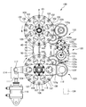
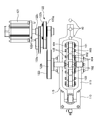
- FIG. 9 is a front view of the rotary press apparatus 100
- FIG. 10 is a plan view of the rotary press apparatus 100.
- the rotary press device 100 sequentially presses the upper punch 40 and the lower punch 50 of the plurality of tablet presses 21 that sequentially pass through the press position P.
- the rotary press device 100 includes a machine frame (not shown), a pair of upper wheels 101, a plurality of upper press rollers (upper pressure contact portions) 102, a pair of lower wheels 106, a plurality of lower press rollers (lower pressure contact portions) 107, A pressure actuator 110 and a rotary drive machine 120 are provided.
- the pair of upper wheels 101 are disposed on the upper side of the movement trajectory of the upper rod 40 along the straight portion 11 b of the upper rail 11. These upper wheels 101 are opposed to each other with a gap therebetween, and are arranged coaxially.
- the upper wheel 101 is attached to the machine frame of the rotary press apparatus 100 and is rotatably provided around a central axis extending in the front-rear direction. Moreover, the center part of a pair of upper wheel 101 is being fixed to the drum 102a (refer FIG. 1) pinched
- a pair of lower wheels 106 are disposed below the upper wheel 101. These lower wheels 106 are arranged below the movement locus of the lower rod 50 along the straight portion 11b of the upper rail 11. These lower wheels 106 are opposed to each other with a gap therebetween and are arranged coaxially. And the lower wheel 106 is rotatably attached to the intermediate part of the link member 115 extended in the left-right direction in FIG.9 and FIG.10. The central axis of the lower wheel 106 is parallel to the central axis of the upper wheel 101. Moreover, the center part of a pair of lower wheel 106 is being fixed to the drum 106a (refer FIG. 1) pinched
- the right end portion 116 of the link member 115 is rotatably attached to the machine frame of the rotary press apparatus 100, and the link member 115 swings up and down with the right end portion 116 as a fulcrum.
- the left end 117 of the link member 115 is connected to the plunger 111 of the pressure actuator 110.
- the pressure actuator 110 is a direct drive source such as a hydraulic cylinder, an air cylinder, or an electromagnetic solenoid.
- the pressure actuator 110 is attached to the machine frame. Accordingly, the pressure actuator 110 pushes up the lower wheel 106 by moving the plunger 111 upward, so that an upward load is applied to the link member 115 and the lower wheel 106.
- the driving method of the pressure actuator 110 is a load control method, and the pressure actuator 110 is controlled so that the load of the pressure actuator 110 is constant. Further, with the load of the pressure actuator 110, a reaction force is generated from the lower wheel 106 to the pressure actuator 110, and when the reaction force exceeds a certain level, the plunger 111 moves backward. Therefore, the load of the pressure actuator 110 does not exceed a certain level.
- a downward load may be applied to the upper wheel 101 by the pressure actuator and the link member in the same manner as an upward load is applied to the lower wheel 106 by the pressure actuator 110 and the link member 115. Further, when a downward load is applied to the upper wheel 101, the pressure actuator 110 and the link member 115 may be omitted, and the lower wheel 106 may be rotatably attached to the machine frame of the rotary press device 100.
- the vertical displacement of the plunger 111 is detected by a displacement sensor 114, and the displacement sensor 114 outputs an output signal representing the detected displacement.
- the output signal of the displacement sensor 114 is used for feedback control of the powder supply device 90. That is, the feedback control circuit inputs the output signal of the displacement sensor 114, and based on the output signal when the tableting machine 21 passes the press position P, the powder supply amount by the powder supply device 90 is set to a constant target value.
- the powder supply apparatus 90 is controlled to maintain.
- the upper wheel 101 and the lower wheel 106 are rotationally driven by a rotational driving machine 120 attached to the machine frame.
- the rotational drive unit 120 transmits a motor 121, a first transmission mechanism 122 that transmits the power of the motor 121 to the upper wheel 101 to rotate the upper wheel 101, and a power of the motor 121 to the lower wheel 106 to transmit the lower wheel 106.
- a second transmission mechanism 123 that rotates the second transmission mechanism 123.
- the first transmission mechanism 122 is a combination of a gear train and a belt transmission mechanism.
- the second transmission mechanism 123 is a belt transmission mechanism.
- the motor 121 is controlled at a constant speed by a constant speed control circuit 124.
- the first transmission mechanism 122 includes a gear 122a, a gear 122b, a pulley 122c, a timing belt 122d, a two-stage pulley 122e, a timing belt 122f, a two-stage pulley 122g, a timing belt 122h, and a pulley 122i.
- a gear 122 a is directly connected to the output shaft of the motor 121.
- the gear 122b meshes with the gear 122a.
- a timing belt 122d is stretched between a pulley 122c provided coaxially with the gear 122b and a large pulley of the two-stage pulley 122e.
- a timing belt 122f is stretched between a small pulley of the two-stage pulley 122e and a large pulley of the two-stage pulley 122g.
- a timing belt 122h is stretched between a pulley 122i provided coaxially with the upper wheel 101 and a small pulley of the two-stage pulley 122g.
- the second transmission mechanism 123 includes a pulley 123a, a timing belt 123b, a two-stage pulley 123c, a timing belt 123d, a two-stage pulley 123f, a timing belt 123g, and a pulley 123i.
- a pulley 123 a is directly connected to the output shaft of the motor 121.
- a timing belt 123b is stretched between the pulley 123a and the large pulley of the two-stage pulley 123c.
- a timing belt 123d is stretched between the small pulley of the two-stage pulley 123c and the large pulley of the two-stage pulley 123f.
- a timing belt 123g is stretched between a small pulley of the two-stage pulley 123f and the pulley 123i.
- the pulley 123 i is provided coaxially with the lower wheel 106.
- a pulley 123f is rotatably attached to the right end portion 116 of the link member 115.
- a drive source for rotationally driving the upper wheel 101 and the lower wheel 106 may be provided separately. Further, the drive source of the rotary drive device 120 and the drive source of the travel drive device 80 are made common, and either the motor 121 or the motor 81 is omitted, and the upper wheel 101, the lower wheel 106, and the tablet press 21 are driven by the other. May be driven.
- a plurality of columnar upper press rollers (upper pressure contact portions) 102 are arranged at equal intervals along the circumferential direction around the central axis of the upper wheel 101.
- These upper press rollers 102 are rotatably attached to the upper wheel 101.
- both ends of a plurality of rotating shafts 103 parallel to the central axis of the upper wheel 101 are respectively fixed to the pair of upper wheels 101, and these rotating shafts 103 are respectively inserted into the upper press rollers 102, A radial load of the press roller 102 is received by the rotating shaft 103.
- the outer peripheral surface of the upper press roller 102 is formed in a cylindrical surface that is coaxial with the rotating shaft 103, and a part of the outer peripheral surface protrudes outward from the outer peripheral surface of the upper wheel 101.
- a disc spring (upper elastic member) 104 is sandwiched between one end surface of the upper press roller 102 and one upper wheel 101, and also between the other end surface of the upper press roller 102 and the other upper wheel 101.
- a disc spring (upper elastic member) 105 is sandwiched.
- a rotating shaft 103 is passed through these disc springs 104 and 105.
- the upper press roller 102 is held by the disc springs 104 and 105 so as to be centered between the pair of upper wheels 101, and the upper press roller 102 moves along the rotation shaft 103 against the elastic force of the disc springs 104 and 105. It is movable.
- a combination of a plurality of upper press rollers 102, a rotating shaft 103, and disc springs 104 and 105 on a pair of upper wheels 101 is referred to as an upper rotary press panel.
- the plurality of cylindrical lower press rollers (lower press contact portions) 107 have their respective rotation shafts.
- a disc spring (lower elastic member), a lower press roller 107 and a disc spring (lower elastic member) are sandwiched between a pair of lower wheels 106.
- the circumferential pitch of the adjacent lower press rollers 107 is equal to the circumferential pitch of the adjacent upper press rollers 102.
- a structure in which a plurality of lower press rollers 107, a shaft 108, and a disc spring are assembled to a pair of lower wheels 106 is referred to as a lower rotary press machine.
- the upper press roller 102 turns around the central axis of the upper wheel 101, and the lower press roller 107 rotates around the central axis of the lower wheel 106.
- the peripheral speeds of the press rollers 102 and 106 are set equal to each other.
- peripheral pitch of the upper press roller 102 is equal to the interval between the upper punches 40 of the adjacent tableting machines 21, and the peripheral pitch of the lower press roller 107 is equal to the interval between the lower punches 50 of the adjacent tableting machines 21. Further, the peripheral speeds of the press rollers 102 and 107 are controlled to be equal to the traveling speed of the tableting machine 21 by the constant speed control circuit 124.
- the powder supply device 90 While the tableting machine 21 is running, the powder supply device 90 performs a periodic powder supply operation. Specifically, in synchronization with the timing when the tableting machine 21 passes through the powder supply device 90, the powder is supplied from the top of the die 30 to the mortar 31 by the powder supply device 90. The position where the powder is supplied by the powder supply device 90 is not in the arc portions 11c and 11d but in the straight portion 11b. Therefore, it is possible to suppress the powder in the mortar hole 31 from being biased by centrifugal force.
- the motor 121 of the rotary drive machine 120 is controlled at a constant speed by a constant speed control circuit 124. Then, the upper wheel 101 and the lower wheel 106 rotate, and the upper press roller 102 and the lower press roller 107 rotate. Further, an upward load is applied to the lower wheel 106 by the pressure actuator 110.
- the timing at which 50 passes the press position P is synchronized.
- the punches 40 and 50 of the tableting machine 21 are pressed so as to be sandwiched between the press rollers 102 and 107 of the rotary press device 100, Tablets are formed from the powder.
- the cam follower 78 of the tablet press 21 is pushed up by the lower punch operation cam 74 and then lowered. It is done.
- the lower punch 50 inserted into the mortar 31 of the mortar 30 is raised and then lowered.
- the tip 52 of the lower punch 50 penetrates upward from the mortar 31 or the tip surface of the tip 52 is aligned with the upper end surface of the die 30, so that the formed tablet is the lower punch 50. It is protruded from the mortar hole 31 by the tip 52. Thereby, the tablets can be collected by a pickup device or the like.
- the position of the lower punch 50 is maintained by the lower punch operation cam 74 until the tableting machine 21 reaches the press position P of the rotary press device 100. Be drunk.
- the powder supply device 90 the powder is supplied to the mortar 31 by the powder supply device 90, and the powder is deposited on the distal end surface of the tip 52 of the lower punch 50.
- the cam follower 77 of the tableting machine 21 is pulled down by the upper punching operation cam 71 after the tableting machine 21 passes through the powder supply device 90 and reaches the rotary press device 100. Thereby, the upper punch 40 is lowered, and the tip 42 of the upper punch 40 is inserted into the mortar 31 of the mortar 30. Then, the powder deposited on the tip 52 of the lower rod 50 is hit from above by the tip 42 of the upper rod 40, and the powder is hit from below by the tip 52 of the lower rod 50. In this way, the powder is preliminarily compressed by the tips 42 and 52.
- the position of the upper punch 40 is maintained by the upper punch operation cam 71 until the tableting machine 21 reaches the press position P of the rotary press device 100. Be drunk.
- the upper press roller 102 passes the lowest point and the lower press roller 107 passes the highest point.
- the upper press roller 102 is pressed against the head 43 of the upper punch 40
- the lower press roller 107 is pressed against the head 53 of the lower punch 50
- the powder sandwiched between the upper punch 40 and the lower punch 50 is removed. It is compressed by the load of the pressure actuator 110. Thereby, powder is solidified.
- the cam follower 77 passes through the interrupted portion of the upper punching operation cam 71 and the cam follower 78 passes through the interrupted portion of the lower punching operation cam 74. Therefore, the load of the pressure actuator 110 does not act on these cams 71 and 74.
- the peripheral speed of the upper press rollers 102 and 106 is equal to the traveling speed of the tableting machine 21, the upper press roller 102 moves from almost right above the head 43 of the upper punch 40 to the head 43 at the pressurization start timing.
- the lower press roller 107 comes into contact with the head 53 almost directly below the head 53 of the lower rod 50. Therefore, the lateral load hardly acts on the flanges 40 and 50. Therefore, pressure is applied to the powder without waste, and the powder is solidified satisfactorily. Moreover, it is not necessary to apply stress to the compression molding apparatus 1.
- the upper press roller 102 contacts the head 43 of the upper collar 40 at a position close to the lowest point. Further, the lowermost part or the vicinity thereof on the outer peripheral surface of the upper press roller 102 is in contact with the head 43 of the upper punch 40, and the upper press roller from the contact portion between the outer peripheral surface of the upper press roller 102 and the head 43 of the upper punch 40.
- a plane connecting up to the central axis 102 is substantially parallel to the vertical direction. Therefore, the tangential component force at the contact portion between the upper press roller 102 and the upper collar 40 is very small, and a lateral load hardly acts on the upper collar 40. Therefore, pressure is applied to the powder without waste, and the powder is solidified satisfactorily.
- the lower press roller 107 contacts the head 53 of the lower punch 50 at a position close to the uppermost point, and from the contact portion between the outer peripheral surface of the lower press roller 107 and the head 53 of the lower punch 50.
- a plane connecting up to the central axis of the lower press roller 107 is substantially parallel to the vertical direction. Therefore, the lateral load hardly acts on the lower eyelid 50.
- the upper press roller 102 comes into contact with the top surface of the head 53 from directly above the head 43 of the upper collar 40, and the lower press roller 107 moves on the head 53 of the lower collar 50. Since the head top surface of the head 53 is contacted from directly below, the head top surfaces of the heads 43 and 53 can be flat surfaces perpendicular to the axes of the upper eyelid 40 and the lower eyelid 50. If the top surfaces of the heads 43 and 53 are flat, almost no component force in the tangential direction is generated even by a load from the press rollers 102 and 107 to the top surfaces of the heads 43 and 53. Therefore, the lateral load hardly acts on the flanges 40 and 50.
- the pressurization actuator 110 applies a constant pressure from 40, 50 to the powder. This is because the pressure actuator 110 is controlled so that the load is constant.
- the upper press roller 102 moves in the circumferential direction around the axis of the upper wheel 101, and the upper rod 40 moves downstream. Since the upper press roller 102 is pressed against the head 43 of the upper punch 40, the upper press roller 102 and the upper presser 40 are moved at the contact portion between the upper press roller 102 and the upper press 40 as the upper press roller 102 moves. There is a risk of tangential loads. However, when the upper press roller 102 rotates around the rotation shaft 103, no slip occurs between the upper press roller 102 and the head 43 of the upper collar 40, and the tangential load is released. Therefore, the lateral load does not act on the upper eyelid 40, and the powder is solidified satisfactorily.
- the lower press roller 107 moves in the circumferential direction and the lower punch 50 moves downstream from the pressurization start timing to the pressurization end timing. As in the case of the upper press roller 102, the lower press roller 107 rotates about the rotation shaft 108, so that a lateral load does not act on the lower rod 50.
- the tablet 30 is modularized by assembling the mortar 30, the upper punch 40, the lower punch 50, the linear motion guide mechanism 60, and the like to the traveling carriage 22. Therefore, there is a degree of freedom in the arrangement shape of these tableting machines 21, and the shape of the locus of the tableting machine 21 is not restricted. Therefore, it is possible to provide the compression molding apparatus 1 in which a plurality of tableting machines 21 are arranged along the oval-shaped rails 11 and 12.
- the rails 11 and 12 can be formed in an oval shape, the rails 11 and 12 have straight portions, and the powder supply device 90 and the rotary press device 100 can be arranged beside the straight portions. In addition, an increase in the area of the region surrounded by the rails 11 and 12 can be minimized while increasing the overall length of the rails 11 and 12.
- the powder supply device 90 and the rotary press device 100 can be arranged along the plurality of rails 11 and 12. Devices other than the powder supply device 90 and the rotary press device 100 are arranged beside the rails 11 and 12, and various processing (for example, cleaning of the die 30, picking up tablets, liquid and solid in the die hole 31) Etc.) can also be performed.
- the linear motion guide mechanism 60 is not provided directly above or directly below the mortar 31, but is provided at a position shifted in the horizontal direction from the mortar 31 of the mortar 30. Therefore, the lubricating oil of the linear motion guide mechanism 60 does not leak into the mortar hole 31.
- the linear motion guide mechanism 60 can be protected from dust and powder by the telescopic pipes 67 and 68.
- the powder supply device 90 and the rotary press device 100 are arranged beside the straight portions of the rails 11 and 12, the powder supply device 90 can supply the powder favorably and pressurize by the rotary press device 100. Can also be performed well.
- the head 43 of the upper collar 40 is pressurized by the upper press roller 102 from directly above, and the head 53 of the lower collar 50 is pressed by the lower press roller 107 from almost immediately below. Pressed.
- the holding body 62 is fixed to the holding plate 24 of the traveling carriage 22, and the shaft 61 can be moved up and down.
- the holding body 62 may not be provided, and the shaft 61 may be fixed to the holding plate 24 so as to vertically penetrate the holding plate 24 of the traveling carriage 22.
- an upper moving body similar to the moving body 63 is disposed on the upper side of the holding plate 24, the shaft 61 is inserted into the upper moving body, and the upper moving body can move up and down along the shaft 61.
- the upper bracket 64 is not assembled to the upper end of the shaft 61 but is assembled to the upper moving body.
- the cam follower 77 is not provided on the bracket 66 but on the rear surface of the upper bracket 64. Therefore, the bracket 66 is not provided.
- the upper rod 40 and the shaft 61 are moved up and down integrally, and the lower rod 50 is moved up and down separately from the shaft 61.
- the lower rod 50 and the shaft 61 may move up and down integrally, and the upper rod 40 may move up and down separately from the shaft 61.
- the moving body 63 and the bracket 66 are not provided, and the lower bracket 65 is assembled to the lower end portion of the shaft 61. Thereby, the lower eyelid 50 and the shaft 61 move up and down integrally.
- an upper moving body similar to the moving body 63 is arranged on the upper side of the holding plate 24, the shaft 61 is inserted into the upper moving body, and the upper moving body can move up and down along the shaft 61.
- the upper bracket 64 is not assembled to the upper end of the shaft 61 but is assembled to the upper moving body. Thereby, the upper collar 40 moves up and down separately from the shaft 61.
- the cam follower 77 is provided on the rear surface of the upper bracket 64.
- the lower punch 50 is lowered after the tablet press 21 has passed through the rotary press device 100 and before the tablet press 21 reaches the powder supply device 90.
- the cam follower 78 of the tableting machine 21 is used for the lower punch operation after the tableting machine 21 passes through the rotary press device 100 and before the tableting machine 21 reaches the powder supply device 90. It may be pushed up later after being pulled down by the cam 74.
- the lower punch 50 that has been inserted into the mortar 31 of the mortar 30 at the time when the tableting machine 21 passes through the rotary press device 100 rises.
- the tip 52 of the lower punch 50 is pulled down from the mortar hole 31, so that the formed tablet falls from the mortar hole 31.
- the tip 52 of the lower punch 50 is inserted into the mortar 31.
- the travel drive device 80 is a chain drive device, but may be a linear motor, a screw drive device, or other drive devices.
- the screw drive device shown in the plan view of FIG. 12 may be applied to the travel drive device 80.
- the lead screw 87 is provided along the straight portion 11 b so as to be parallel to the straight portion 11 b of the upper rail 11.
- the lead screw 87 is rotatably supported by a bearing or the like.
- a spiral groove 88 is formed on the outer peripheral surface of the lead screw 87.
- sliding pieces 89 are provided on the rear surface of the roller support plate 23 of each tableting machine 21, and these sliding pieces 89 are inserted into the grooves 88.
- the tableting machine 21 runs.
- a lead screw similar to the lead screw 87 may be provided along the opposite linear portion 11a, and the tableting machine 21 may be driven by the rotation of the lead screw.
- the installation position of the rotary press device 100 is beside the linear portion 11b of the upper rail 11, but may be beside the circular arc portion 11d of the upper rail 11. Since the tableting machine 21 draws an arc-shaped trajectory in the arc portion 11d, it is effective that the upper press roller 102 is movable along the rotation shaft 103. That is, from the time when the upper press roller 102 comes into contact with the head 43 of the upper collar 40 at the pressurization start timing until the upper press roller 102 reaches the lowest point, the upper press is performed by the head 43 that draws an arc-shaped locus. The roller 102 is moved in the direction of the rotation shaft 103, and the disc spring 104 (or disc spring 105) is compressed.
- the upper press roller 102 From the time when the upper press roller 102 reaches the lowest point until the upper press roller 102 moves away from the head 43 of the upper collar 40 at the end of pressurization, the upper press roller 102 is opposed by the head 43 that draws an arcuate path.
- the disc spring 104 (or disc spring 105) is restored.
- Such movement of the upper press roller 102 prevents slippage between the upper press roller 102 and the head 43 of the upper collar 40 and prevents the upper press roller 102 and the upper wheel 101 from being overloaded. be able to.
- the rails 11 and 12 have an oval shape.
- the rails 11 and 12 are not limited to the oval shape as long as the rails 11 and 12 have a closed curve shape.
- roller chain 85 ... constant speed control path, 90 ... Powder supply device, 100 ... rotary press device, 101 ... upper wheel, 102 ... upper press roller (upper pressure contact portion), 103 ... rotating shaft, 104 ... disc spring (upper elastic member), 105 ... disc spring (upper elastic member) 106: Lower wheel, 107: Lower press roller (lower pressure contact part), 108: Rotating shaft, 110: Pressurization act Eta (pressurizer), 111 ... plunger, 114 ... displacement sensor, 115 ... link member, 116 ... right end of link member, 117 ... left end of link member, 120 ... rotary drive, 121 ... motor, 122 ... first One transmission mechanism, 122a ... gear, 122b ...
Landscapes
- Engineering & Computer Science (AREA)
- Mechanical Engineering (AREA)
- Medical Preparation Storing Or Oral Administration Devices (AREA)
Abstract
杵が倒れる方向の荷重をその杵に与えないようにする。 プレス位置Pを順次通過する複数の上杵40及び複数の下杵50をプレス位置Pにおいて順次プレスするプレス装置100は、プレス位置Pの上側の中心軸回りに回転可能に設けられたアッパーホイール101と、アッパーホイール101の中心軸回りの周方向に沿って配列されるようにアッパーホイール101に取り付けられ、上杵40の上端43の頭部に圧接する複数の上部プレスローラー102と、プレス位置Pの下側の中心軸回りに回転可能に設けられたロアホイール106と、ロアホイール106の中心軸回りの周方向に沿って配列されるようにロアホイール106に取り付けられ、下杵50の下端の頭部に圧接する複数の下部プレスローラー107と、を備える。
Description
本発明は、上杵と下杵の間に挟まれた粉末を前記上杵及び前記下杵を通じてプレスするプレス装置に関するとともに、そのプレス装置に利用されるロータリープレス盤に関する。
特許文献1で用いられた符号を括弧書きで表記し、特許文献1に記載の技術について説明する。特許文献1には、臼(4)、上杵(5)及び下杵(6)を用いて粉末を圧縮することによって固形化する粉末圧縮成形装置(A)が開示されている。臼(4)、上杵(5)及び下杵(6)は複数あり、鉛直な軸回りに回転する回転盤(3)に複数の臼(4)、上杵(5)及び下杵(6)が組み付けられている。具体的には、回転盤(3)の上部(31)の外周部には、複数の上杵(5)が周方向に等間隔で配列されるようにして取り付けられ、これら上杵(5)が個別に昇降可能に設けられている。また、上杵(5)の場合と同様に、昇降可能な複数の下杵(6)が周方向に等間隔で配列されるようにして回転盤(3)の下部(32)に取り付けられている。更に、臼(4)は周方向に等間隔で配列されるようにして回転盤(3)の高さ方向中間部(33)に取り付けられている。回転盤(3)の周囲には、粉末供給装置(7)及び上下一対の加圧ロール(84,85)が配置されている。そして、回転盤(3)の回転中に、臼(3)が粉末供給装置(7)を通過する際に、その粉末供給装置(7)によって粉末が臼(3)に供給され、その後、臼(3)、上杵(5)及び下杵(6)が一対の加圧ロール(84,85)の間を通過する際に、上杵(5)及び下杵(6)が一対の加圧ロール(84,85)の間に挟み込まれ、上杵(5)及び下杵(6)によって臼(4)内の粉末が圧縮される。
これら加圧ロール(84,85)はそれぞれの水平な中心軸回りに回転可能に設けられ、これら加圧ロール(84,85)の間隔は一定に保たれている。そして、上杵(5)は上側の加圧ロール(84)に圧接され、下杵(6)は下側の加圧ロール(85)に圧接され、これら加圧ロール(84,85)は上杵(5)及び下杵(6)の移動に従動して回転する。
ここで、図13は、上杵及び下杵が一対の加圧ロールの間を通過する際の上杵の頭部及び上側の加圧ロールの動きを示したものである。図13に示すように、上杵200が図中左から右へ移動し、加圧ロール202が図中反時計回りに回転するものとする。上杵200が加圧ロール202の外周面の最下部203に到達する前に(矢印T参照)、上杵200が加圧ロール202の外周面のうち最下部203からずれた位置に接触する。そして、加圧ロール202は、上杵200の移動に従動して回転する。
そのため、上杵200が加圧ロール202に圧接されている際に、上杵200と加圧ロール202の間の摩擦によって横方向の荷重が上杵200に作用する。このような荷重は装置にストレスを与えるものであるとともに、粉末の固形化に悪影響を及ぼす。
同様に、下杵が下側の加圧ロールの外周面の最下部に到達する前に、下杵が下側の加圧ロールに接触し、下杵の移動に従動して下側の加圧ロールが回転し、下杵にも同様な横方向の荷重が作用する。
そのため、上杵200が加圧ロール202に圧接されている際に、上杵200と加圧ロール202の間の摩擦によって横方向の荷重が上杵200に作用する。このような荷重は装置にストレスを与えるものであるとともに、粉末の固形化に悪影響を及ぼす。
同様に、下杵が下側の加圧ロールの外周面の最下部に到達する前に、下杵が下側の加圧ロールに接触し、下杵の移動に従動して下側の加圧ロールが回転し、下杵にも同様な横方向の荷重が作用する。
そこで、本発明は、上記事情に鑑みてなされたものである。本発明が解決しようとする課題は、横方向の荷重を杵に与えないようにすることである。
以上の課題を解決するべく、所定のプレス位置を順次通過する複数の上杵及び前記上杵の下側にある複数の下杵をそのプレス位置において順次プレスするプレス装置は、前記プレス位置の上側において回転可能に設けられたアッパーホイールと、前記アッパーホイールの周方向に沿って配列されるように前記アッパーホイールに取り付けられ、前記上杵の上端の頭部に圧接する複数の上部圧接部と、前記プレス位置の下側において回転可能に設けられたロアホイールと、前記ロアホイールの周方向に沿って配列されるように前記ロアホイールに取り付けられ、前記下杵の下端の頭部に圧接する複数の下部圧接部と、を備える。
本発明の他の特徴については、後述する明細書及び図面の記載により明らかにする。
本発明の他の特徴については、後述する明細書及び図面の記載により明らかにする。
本発明によれば、杵が倒れる方向の荷重が杵に付与されないようにすることができる。
後述する明細書及び図面の記載から、少なくとも以下の事項が明らかとなる。
所定のプレス位置を順次通過する複数の上杵及び前記上杵の下側にある複数の下杵をそのプレス位置において順次プレスするプレス装置において、前記プレス位置の上側において回転可能に設けられたアッパーホイールと、前記アッパーホイールの周方向に沿って配列されるように前記アッパーホイールに取り付けられ、前記上杵の上端の頭部に圧接する複数の上部圧接部と、前記プレス位置の下側において回転可能に設けられたロアホイールと、前記ロアホイールの周方向に沿って配列されるように前記ロアホイールに取り付けられ、前記下杵の下端の頭部に圧接する複数の下部圧接部と、を備えるプレス装置が明らかとなる。
また、回転可能なホイールと、前記ホイールの中心軸からずれた位置において前記ホイールに取り付けられ、杵先で粉末を打つ杵の頭部に圧接する圧接部と、を備えるロータリープレス盤が明らかとなる。
所定のプレス位置を順次通過する複数の上杵及び前記上杵の下側にある複数の下杵をそのプレス位置において順次プレスするプレス装置において、前記プレス位置の上側において回転可能に設けられたアッパーホイールと、前記アッパーホイールの周方向に沿って配列されるように前記アッパーホイールに取り付けられ、前記上杵の上端の頭部に圧接する複数の上部圧接部と、前記プレス位置の下側において回転可能に設けられたロアホイールと、前記ロアホイールの周方向に沿って配列されるように前記ロアホイールに取り付けられ、前記下杵の下端の頭部に圧接する複数の下部圧接部と、を備えるプレス装置が明らかとなる。
また、回転可能なホイールと、前記ホイールの中心軸からずれた位置において前記ホイールに取り付けられ、杵先で粉末を打つ杵の頭部に圧接する圧接部と、を備えるロータリープレス盤が明らかとなる。
以上のようなプレス装置及びロータリープレス盤によれば、アッパーホイール及びロアホイールが回転すると、上部圧接部及び下部圧接部が旋回し、上部圧接部及び下部圧接部が円状の軌跡を描く。そのため、上杵がプレス位置を通過するとともに上部圧接部が最下部を通過する直前においては、上部圧接部は下方に向けて上杵の頭部に近づきつつ、上杵の頭部の移動に合わせて横方向に移動する。そのため、上部圧接部が上杵の頭部の直上から上杵の頭部に接触する。そのため、横方向の荷重が上杵に付与されない。
同様に、下部圧接部が下杵の頭部の直下から下杵の頭部に接触するので、横方向の荷重が下杵に付与されない。
同様に、下部圧接部が下杵の頭部の直下から下杵の頭部に接触するので、横方向の荷重が下杵に付与されない。
好ましくは、前記プレス装置において、前記上部圧接部が前記アッパーホイールの中心軸に対して平行な軸の回りに回転可能に前記アッパーホイールに取り付けられ、前記下部圧接部が前記ロアホイールの中心軸に対して平行な軸の回りに回転可能に前記ロアホイールに取り付けられている。より好ましくは、前記上部圧接部がその軸回りの円柱面状に形成された外周面を有し、前記下部圧接部がその軸回りの円柱面状に形成された外周面を有する。
好ましくは、前記ロータリープレス盤において、前記圧接部が前記ホイールの中心軸に対して平行な軸の回りに回転可能に前記ホイールに取り付けられている。より好ましくは、前記圧接部がその軸回りの円柱面状に形成された外周面を有する。
好ましくは、前記ロータリープレス盤において、前記圧接部が前記ホイールの中心軸に対して平行な軸の回りに回転可能に前記ホイールに取り付けられている。より好ましくは、前記圧接部がその軸回りの円柱面状に形成された外周面を有する。
以上のようなプレス装置及びロータリープレス盤によれば、上杵がプレス位置を通過する際に、上杵の頭部に圧接した上部圧接部が回転することによって、上部圧接部と上杵の頭部との間で滑りが発生しない。そのため、上杵が倒れる方向の荷重は上杵に付与されない。下杵と下部圧接部についても同様である。
好ましくは、前記プレス装置が上部弾性部材及び下部弾性部材を更に備え、前記上部圧接部が前記アッパーホイールの中心軸に対して平行な方向に移動可能となって前記アッパーホイールに取り付けられ、前記上部弾性部材が前記上部圧接部の移動に抗して前記上部圧接部を保持し、前記下部圧接部が前記ロアホイールの中心軸に対して平行な方向に移動可能となって前記ロアホイールに取り付けられ、前記下部弾性部材が前記下部圧接部の移動に抗して前記下部圧接部を保持する。
以上のようなプレス装置によれば、上杵及び下杵がプレス位置を通過する際の軌跡が曲線である場合、上杵の頭部に圧接した上部圧接部が軸方向に移動することによって、上部圧接部と上杵の頭部との間で滑りが発生しない。そのため、上杵が倒れる方向の荷重は上杵に付与されない。下杵と下部圧接部についても同様である。
また、上部圧接部が軸方向に移動した後、上部弾性部材の弾性力によって上部圧接部が元の位置に戻る。下部圧接部についても同様である。
また、上部圧接部が軸方向に移動した後、上部弾性部材の弾性力によって上部圧接部が元の位置に戻る。下部圧接部についても同様である。
好ましくは、前記プレス装置において、前記上部圧接部の隣同士の周ピッチが上記上杵の隣同士の間隔に等しく、前記下部圧接部の隣同士の周ピッチが上記下杵の隣同士の間隔に等しい。
以上のようなプレス装置によれば、上部圧接部が上杵の頭部の直上から上杵の頭部に接触し、上部圧接部の動きを上杵の移動に合わせることができる。下部圧接部が下杵の頭部の直下から下杵の頭部に接触し、下杵圧接部の動きを上杵の移動に合わせることができる。そのため、上杵及び下杵が倒れる方向の荷重の発生をより効率よく抑えることができる。
好ましくは、前記プレス装置が、前記アッパーホイール及び前記ロアホイールを回転駆動する回転駆動機を更に備える。
更に好ましくは、前記上杵が前記プレス位置を通過するタイミングに同期して、前記上部圧接部が前記プレス位置を通過するように、前記回転駆動機が前記アッパーホイールを回転駆動し、前記下杵が前記プレス位置を通過するタイミングに同期して、前記下部圧接部が前記プレス位置を通過するように、前記回転駆動機が前記ロアホイールを回転駆動する。
更に好ましくは、前記アッパーホイールの中心軸回りの前記上部圧接部の周速度が前記上杵の移動速度と等しくなるように、前記回転駆動機が前記アッパーホイールを回転駆動し、前記ロアホイールの中心軸回りの前記下部圧接部の周速度が前記下杵の移動速度と等しくなるように、前記回転駆動機が前記ロアホイールを回転駆動する。
更に好ましくは、前記上杵が前記プレス位置を通過するタイミングに同期して、前記上部圧接部が前記プレス位置を通過するように、前記回転駆動機が前記アッパーホイールを回転駆動し、前記下杵が前記プレス位置を通過するタイミングに同期して、前記下部圧接部が前記プレス位置を通過するように、前記回転駆動機が前記ロアホイールを回転駆動する。
更に好ましくは、前記アッパーホイールの中心軸回りの前記上部圧接部の周速度が前記上杵の移動速度と等しくなるように、前記回転駆動機が前記アッパーホイールを回転駆動し、前記ロアホイールの中心軸回りの前記下部圧接部の周速度が前記下杵の移動速度と等しくなるように、前記回転駆動機が前記ロアホイールを回転駆動する。
以上のようなプレス装置によれば、上部圧接部が上杵の頭部の直上から上杵の頭部に接触し、上部圧接部の動きを上杵の移動に合わせることができる。下部圧接部が下杵の頭部の直下から下杵の頭部に接触し、下部圧接部の動きを下杵の移動に合わせることができる。そのため、上杵及び下杵が倒れる方向の荷重の発生をより効率よく抑えることができる。
好ましくは、前記プレス装置が、前記アッパーホイールと前記ロアホイールが近づく方向の負荷を前記アッパーホイールと前記ロアホイールの少なくとも一方に付与する加圧機を更に備える。
更に好ましくは、前記加圧機が一定の負荷を前記アッパーホイールと前記ロアホイールの少なくとも一方に付与する。
更に好ましくは、前記加圧機が一定の負荷を前記アッパーホイールと前記ロアホイールの少なくとも一方に付与する。
以上のようなプレス装置によれば、粉末に適切な圧力を付与することができ、粉末の固形化を良好に行える。
〔実施の形態〕
以下、図面を参照して、本発明の実施形態について説明する。但し、以下に述べる実施形態には、本発明を実施するために技術的に好ましい種々の限定が付されているので、本発明の範囲を以下の実施形態及び図示例に限定するものではない。
以下、図面を参照して、本発明の実施形態について説明する。但し、以下に述べる実施形態には、本発明を実施するために技術的に好ましい種々の限定が付されているので、本発明の範囲を以下の実施形態及び図示例に限定するものではない。
1. 圧縮成形装置の概要
図1は、圧縮成形装置1の斜視図である。図2は、圧縮成形装置1の平面図である。図3は、打錠機列20の斜視図である。
図1及び図2に示すように、圧縮成形装置1は、走行ガイド10、打錠機列20、打錠動作用カム70、走行用駆動装置80、粉末供給装置90及び回転プレス装置100等を備える。
図1は、圧縮成形装置1の斜視図である。図2は、圧縮成形装置1の平面図である。図3は、打錠機列20の斜視図である。
図1及び図2に示すように、圧縮成形装置1は、走行ガイド10、打錠機列20、打錠動作用カム70、走行用駆動装置80、粉末供給装置90及び回転プレス装置100等を備える。
走行ガイド10は、閉じた経路である。この走行ガイド10は、閉曲線状としてのオーバル形状に形作られたアッパーレール11及びロアレール12を有する。これらアッパーレール11及びロアレール12は、水平に、且つ、これらの間に上下に間隔を置いて互いに平行に設けられている。ここで、オーバル形状とは、楕円形又はそれに近似した形状をいい、楕円のほかに長円形、角丸長方形、卵形もオーバル形状の一種である。角丸長方形とは、長方形の角部が円弧状に形成されたものである。アッパーレール11は、角丸長方形の中でも特に短辺部全体が円弧状になったものである。つまり、アッパーレール11は、互いに長さが等しく互いに平行な二本の直線部11a,11bと、これら直線部11a,11bの一方の端部間に連結された一方の半円状の円弧部11cと、これら直線部11a,11bの他方の端部間に連結された他方の半円状の円弧部11dとからなる。ロアレール12についてもアッパーレール11と同様である。
図3に示すように、打錠機列20は、モジュール化された複数の打錠機21を有する。これら打錠機21が走行ガイド10に沿って等間隔で配列されることによって、打錠機列20が構成される。これら打錠機21は走行ガイド10の全周に渡って配列されているが、図1及び図2において走行ガイド10及び打錠用動作カム70を見やすくするために、一部の打錠機21を図示する。また、図2において、走行用駆動装置80の図示を省略する。
図1に示すように、これら打錠機21は、走行ガイド10に支持されているとともに、走行ガイド10に沿って案内される。走行用駆動装置80は、打錠機21に動力を付与して、上から見て反時計回りの方向(図2の矢印A参照)へ打錠機21を走行させる。これにより、打錠機21が走行ガイド10に沿って周回される。打錠動作用カム70は、打錠機21の走行に伴って、打錠機21に打錠動作を行わせるものである。打錠機21の走行経路上の所定の位置(特に、アッパーレール11の直線部11bの脇)に設けられた粉末供給装置90は、粉末を複数の打錠機21(特に、後述の臼30の臼孔31)に順次供給する。打錠機21の走行経路上の所定の位置(特に、アッパーレール11の直線部11bの脇)に設けられた回転プレス装置100は、打錠機21に打たれた粉末をプレスして、粉末を固形化する。圧縮された粉末から錠剤が成形される。複数の打錠機21がプレス装置100を順次通過するので、これら打錠機21に供給された粉末がプレス装置100によって順次プレスされる。
なお、粉末供給装置90が複数設けられ、これら粉末供給装置90がアッパーレール11の直線部11bに沿って配列され、これら粉末供給装置90が異なる粉体を打錠機21に供給してもよい。また、小片移載装置が粉末供給装置90に並列され、小片移載装置に供給される小片(例えばICチップ、能動素子、受動素子等の電子部品や、固形剤)が小片移載装置によって打錠機21(特に、後述の臼30の臼孔31)に移載されてもよい。
2. 打錠機の構成
図4~図8を参照して、打錠機21について詳細に説明する。図4は、打錠機21を前側、上側且つ右側から見て示した斜視図である。図5は、打錠機21を後ろ側、上側且つ左側から見て示した斜視図である。図6は、打錠機21の右側面図である。図7は、打錠機21の平面図である。図8は、図7に示すVIII-VIIIに沿って打錠機21の一部を切断して示した断面図である。なお、打錠機21の前面とは、走行ガイド10の外側を向く面をいい、打錠機21の後面とは、走行ガイド10の内側を向く面をいう。
図4~図8を参照して、打錠機21について詳細に説明する。図4は、打錠機21を前側、上側且つ右側から見て示した斜視図である。図5は、打錠機21を後ろ側、上側且つ左側から見て示した斜視図である。図6は、打錠機21の右側面図である。図7は、打錠機21の平面図である。図8は、図7に示すVIII-VIIIに沿って打錠機21の一部を切断して示した断面図である。なお、打錠機21の前面とは、走行ガイド10の外側を向く面をいい、打錠機21の後面とは、走行ガイド10の内側を向く面をいう。
打錠機21は走行キャリッジ22、臼30、上杵40、下杵50、直動案内機構60、ブラケット64~66及びカムフォロワー77,78等を備える。
走行キャリッジ22は、左側又は右側から見て、横T字型に設けられている。つまり、走行キャリッジ22が矩形板状のローラー支持盤23及び保持盤24を有し、ローラー支持盤23が立てられた状態で走行ガイド10に支持され、保持盤24がローラー支持盤23の前面の高さ方向中間部から前方に延出する。
ローラー支持盤23の後面には、それぞれ二輪の走行ローラー25~28が回転可能に設けられている。これら走行ローラー25~28の回転軸はローラー支持盤23の後面から後方へ延びる。これら走行ローラー25~28は上下四段に設けられている。
ローラー支持盤23がレール11,12の外側に配置され(図1、図2及び図6等参照)、保持盤24がレール11,12の外方へ延出する。そして、走行ローラー25と走行ローラー26がこれらの間にアッパーレール11を挟み込むことによって、走行キャリッジ22がアッパーレール11に支持される。同様に、走行キャリッジ22が走行ローラー27,28によってロアレール12に支持される。走行ローラー25,26がアッパーレール11に対して転動し、走行ローラー27,28がロアレール12に対して転動し、これにより走行キャリッジ22がレール11,12の外側においてレール11,12に沿って走行する。走行ローラー25~28によって走行キャリッジ22の走行が滑らかになるとともに、安定する。
保持盤24の先端側部位には、臼30が設けられている。具体的には、装着孔24aが保持盤24の先端側部位を上下に貫通するように設けられ、臼30が装着孔24aに嵌め込まれ、止めねじ34によって臼30が保持盤24に固定されている。止めねじ34は保持盤24の先端面から装着孔24aに向けて締め付けられ、止めねじ34の先端が臼30の外周面に押し付けられている。臼30には臼孔31が形成されている。臼孔31は、臼30を上下に貫通している。
臼30の上側に上杵40が配置され、臼30の下側に下杵50が配置され、上杵40、下杵50及び臼孔31が同心状に配列されている。
上杵40は胴部41、杵先42及び頭部43を有する。胴部41は上杵40の本体部分を成す。胴部41が柱状に設けられ、胴部41の軸線が上下方向に延びる。杵先42が胴部41の下端に設けられ、頭部43が胴部41の上端に設けられている。杵先42が胴部41よりも細い柱状に設けられ、杵先42の軸線が上下方向に延びる。頭部43が胴部41よりも径の大きな円盤状に設けられている。頭部43の頭頂面は平坦に形成されているとともに、上杵40及び胴部41の軸線に対して直交する。
下杵50は胴部51、杵先52及び頭部53を有し、上杵40と上下対称の構成を有している。つまり、柱状の胴部51の軸線が上下方向に延び、胴部51よりも細い柱状の杵先52が胴部51の上端に設けられ、胴部51よりも大径の頭部53が胴部51の下端に設けられている。
下杵50は胴部51、杵先52及び頭部53を有し、上杵40と上下対称の構成を有している。つまり、柱状の胴部51の軸線が上下方向に延び、胴部51よりも細い柱状の杵先52が胴部51の上端に設けられ、胴部51よりも大径の頭部53が胴部51の下端に設けられている。
上杵40及び下杵50は、直動案内機構60によって上下動可能となって走行キャリッジ22に組み付けられている。直動案内機構60は上杵40と下杵50を個別に案内するものであり、直動案内機構60による上杵40の上下方向の案内と直動案内機構60による下杵50の上下方向の案内は独立している。上杵40が直動案内機構60によって下方に案内されると、上杵40の杵先42が臼孔31に挿入され、下杵50が直動案内機構60によって上方に案内されると、下杵50の杵先52が臼孔31に挿入される。
直動案内機構60はボールスプライン型案内機構である。直動案内機構60はシャフト61、保持体62、移動体63及び多数のボール等を有する。シャフト61がスプライン軸であり、シャフト61の軸線に対して平行な複数の溝がシャフト61の外周面に形成されている。保持体62及び移動体63が筒状に設けられ、シャフト61が保持体62及び移動体63に挿入され、シャフト61のラジアル荷重が保持体62及び移動体63に受けられる。保持体62の内周面には複数のボールが転動可能に保持され、それらボールがシャフト61の外周面の溝に収容され、シャフト61の周方向荷重がボールを介して保持体62に受けられる。同様にして、シャフト61の外周面と移動体63の内周面との間に複数のボールが介在した状態で、移動体63がシャフト61に組み付けられている。従って、移動体63及び保持体62はシャフト61に対して相対的に軸方向に沿って直線移動可能であるが、移動体63及び保持体62の軸回りの回転がシャフト61及びボールによって規制されている。
以上のような直動案内機構60は走行キャリッジ22に組み付けられている。具体的には、保持孔24bが保持盤24の中間部位を上下に貫通するように設けられ、保持体62が保持孔24bに嵌め込まれ、その保持体62が保持盤24に固定されている。直動案内機構60が走行キャリッジ22に組み付けられた状態では、シャフト61が保持盤24を上下方向に貫通し、移動体63が保持盤24の下方に配置される。そして、シャフト61及び移動体63が保持盤24に対して相対的に上下動可能である。
シャフト61の上端部に上部ブラケット64が組み付けられ、その上部ブラケット64がシャフト61の上端部から前方に延出する。上部ブラケット64とシャフト61はねじ等によって固定されている。
上部ブラケット64の先端部には上杵40が組み付けられている。具体的には、上杵40の胴部41が上部ブラケット64の先端部を上下に貫通して、上部ブラケット64が上杵40の胴部41を左右にクランプし、上杵40の頭部43が上部ブラケット64に上面に当接し、上杵40の杵先42が上部ブラケット64から下方に突き出て、この状態で胴部41がねじ等によって上部ブラケット64に締結されている。従って、上杵40と上部ブラケット64とシャフト61は一体となって上下動する。
移動体63には下部ブラケット65が組み付けられ、その下部ブラケット65が移動体63から前方に延出する。下部ブラケット65と移動体63はねじ等によって固定されている。
保持盤24よりも上側において、シャフト61が蛇腹状の上部伸縮管(上部カバー)67に挿入されることによって、シャフト61が部分的に上部伸縮管67によって覆われている。上部伸縮管67の上端が上部ブラケット64に連結され、上部伸縮管67の下端が保持体62又は保持盤24に連結されている。上部ブラケット64の昇降に伴って、上部伸縮管67が伸縮する。上部伸縮管67によってシャフト61が保護され、塵埃や粉体等がシャフト61と保持体62の間の隙間等に進入することを防止することができる。
保持盤24よりも下側において、シャフト61が蛇腹状の下部伸縮管(下部カバー)68に挿入されることによって、シャフト61が部分的に下部伸縮管68によって覆われている。下部伸縮管68の上端が保持体62又は保持盤24に連結され、下部伸縮管68の下端が移動体63又は下部ブラケット65に連結されている。下部ブラケット65の昇降に伴って、下部伸縮管68が伸縮する。下部伸縮管68によって塵埃や粉体等の進入を防止することができる。
下部ブラケット65の先端部には下杵50が組み付けられている。具体的には、下杵50の胴部51が下部ブラケット65の先端部を上下に貫通して、下部ブラケット64が下杵50の胴部51を左右にクランプし、下杵50の頭部53が下部ブラケット65に下面に当接し、下杵50の杵先52が下部ブラケット65から上方に突き出て、この状態で胴部51がねじ等によって下部ブラケット65に締結されている。従って、下杵50と下部ブラケット65と移動体65は一体となって上下動する。
シャフト61の下端部には、ブラケット66が固定されている。ブラケット66の後面には、カムフォロワー77が取り付けられている。また、下部ブラケット65の後面にも、カムフォロワー78が取り付けられている。カムフォロワー77,78は打錠動作用カム70によって昇降される。
なお、蛇腹状の伸縮管(カバー)がブラケット66と下部ブラケット65との間にも設けられ、シャフト61がその伸縮管に挿入され、その伸縮管の上端が下部ブラケット65又は移動体63に連結され、その伸縮管の下端がブラケット66に連結されてもよい。また、カムフォロワー77が上部ブラケット64の後面に設けられてもよい。
なお、蛇腹状の伸縮管(カバー)がブラケット66と下部ブラケット65との間にも設けられ、シャフト61がその伸縮管に挿入され、その伸縮管の上端が下部ブラケット65又は移動体63に連結され、その伸縮管の下端がブラケット66に連結されてもよい。また、カムフォロワー77が上部ブラケット64の後面に設けられてもよい。
3. 打錠機の動力
続いて、図2を参照して、走行用駆動装置80について詳細に説明する。
走行用駆動装置80は、動力を打錠機21の走行キャリッジ22に伝達して、走行キャリッジ22を走行させるものである。走行用駆動装置80は、モーター81、駆動スプロケット82、従動スプロケット83及びローラーチェーン84等を有するチェーン駆動装置である。モーター81の出力軸が駆動スプロケット82に連結されている。駆動スプロケット82が走行ガイド10の一方の半円部の内側に配され、従動スプロケット83が走行ガイド10の他方の半円部の内側に配されている。ローラーチェーン84が無端状(閉曲線状)に設けられていて、駆動スプロケット82と従動スプロケット83との間に掛け渡されている。図4~図8に示すように走行キャリッジ22のローラー支持盤23の後面がローラーチェーン84に連結されており、各走行キャリッジ22がローラーチェーン84によって連なっている。モーター81によってローラーチェーン84が周回され、モーター81の動力がローラーチェーン84によって走行キャリッジ22に伝達することによって、走行キャリッジ22が走行する。モーター81が定速制御回路85によって定速制御され、これにより走行キャリッジ22が定速走行する。なお、ローラーチェーン84の代わりに無端状ベルトを採用し、スプロケット82,83の代わりにプーリーを採用することで、走行用駆動装置80をベルト駆動装置としてもよい。
続いて、図2を参照して、走行用駆動装置80について詳細に説明する。
走行用駆動装置80は、動力を打錠機21の走行キャリッジ22に伝達して、走行キャリッジ22を走行させるものである。走行用駆動装置80は、モーター81、駆動スプロケット82、従動スプロケット83及びローラーチェーン84等を有するチェーン駆動装置である。モーター81の出力軸が駆動スプロケット82に連結されている。駆動スプロケット82が走行ガイド10の一方の半円部の内側に配され、従動スプロケット83が走行ガイド10の他方の半円部の内側に配されている。ローラーチェーン84が無端状(閉曲線状)に設けられていて、駆動スプロケット82と従動スプロケット83との間に掛け渡されている。図4~図8に示すように走行キャリッジ22のローラー支持盤23の後面がローラーチェーン84に連結されており、各走行キャリッジ22がローラーチェーン84によって連なっている。モーター81によってローラーチェーン84が周回され、モーター81の動力がローラーチェーン84によって走行キャリッジ22に伝達することによって、走行キャリッジ22が走行する。モーター81が定速制御回路85によって定速制御され、これにより走行キャリッジ22が定速走行する。なお、ローラーチェーン84の代わりに無端状ベルトを採用し、スプロケット82,83の代わりにプーリーを採用することで、走行用駆動装置80をベルト駆動装置としてもよい。
続いて、図1を参照して、打錠動作用カム70について詳細に説明する。
打錠動作用カム70は、打錠機21の走行時の動力を上杵40及び下杵50の昇降運動の動力に変換するものである。打錠動作用カム70は上杵動作用カム71及び下杵動作用カム74を有する。
打錠動作用カム70は、打錠機21の走行時の動力を上杵40及び下杵50の昇降運動の動力に変換するものである。打錠動作用カム70は上杵動作用カム71及び下杵動作用カム74を有する。
上杵動作用カム71は上下一対の帯板カム72及びスリット部73を有する。一対の帯板カム72が走行ガイド10に沿って周方向に、且つ上下に間隔を置いて互いに平行に設けられ、これら帯板カム72の間にスリット部73が形成されている。カムフォロワー77がスリット部73に挿入されて、上下の帯板カム72の間に挟まれている。スリット部73は上下方向の位置が一定ではなく、周方向の位置に応じて上下方向の位置が設定されている。そのため、カムフォロワー77が帯板カム72に沿って周方向に摺動することによって上下方向に変位する。従って、打錠機21の周回に伴って、上杵40が昇降する。
下杵動作用カム74も上下一対の帯板カム75及びスリット部76を有し、スリット部76に挿入されたカムフォロワー78が帯板カム75に沿って周方向に摺動することによって上下方向に変位する。従って、打錠機21の周回に伴って、下杵50が昇降する。
上杵動作用カム71の帯板カム72は、無端状ではなく、回転プレス装置100のプレス位置P(図1、図9参照)において途切れており、その部分ではカムフォロワー77が帯板カム72に支持されない。同様に、下杵動作用カム74の帯板カム75も回転プレス装置100のプレス位置Pにおいて途切れている。ここで、プレス位置Pとは、後述するアッパーホイール101の中心軸とロアホイール106の中心軸との間の部位をいう。
4. 回転プレス装置の構成
続いて、図1、図9及び図10を参照して、回転プレス装置100について詳細に説明する。ここで、図9は回転プレス装置100の正面図であり、図10は回転プレス装置100の平面図である。
回転プレス装置100は、プレス位置Pを順次通過する複数の打錠機21の上杵40と下杵50を順次プレスするものである。回転プレス装置100は、機枠(図示略)、一対のアッパーホイール101、複数の上部プレスローラー(上部圧接部)102、一対のロアホイール106、複数の下部プレスローラー(下部圧接部)107、加圧アクチュエータ110及び回転駆動機120等を備える。
続いて、図1、図9及び図10を参照して、回転プレス装置100について詳細に説明する。ここで、図9は回転プレス装置100の正面図であり、図10は回転プレス装置100の平面図である。
回転プレス装置100は、プレス位置Pを順次通過する複数の打錠機21の上杵40と下杵50を順次プレスするものである。回転プレス装置100は、機枠(図示略)、一対のアッパーホイール101、複数の上部プレスローラー(上部圧接部)102、一対のロアホイール106、複数の下部プレスローラー(下部圧接部)107、加圧アクチュエータ110及び回転駆動機120等を備える。
一対のアッパーホイール101は、アッパーレール11の直線部11bに沿った上杵40の移動軌跡の上側に配置されている。これらアッパーホイール101は、それらの間に間隔を置いて前後に対向するとともに、同軸状に配置されている。そして、アッパーホイール101は回転プレス装置100の機枠に取り付けられているとともに、前後方向に延びた中心軸回りに回転可能に設けられている。また、一対のアッパーホイール101の中心部がそれらの間に挟まれたドラム102a(図1参照)に固定されている。
アッパーホイール101の下方には、一対のロアホイール106が配置されている。これらロアホイール106は、アッパーレール11の直線部11bに沿った下杵50の移動軌跡の下側に配置されている。これらロアホイール106は、それらの間に間隔を置いて前後に対向するとともに、同軸状に配置されている。そして、ロアホイール106は、図9及び図10中の左右方向に延びたリンク部材115の中間部に回転可能に取り付けられている。ロアホイール106の中心軸はアッパーホイール101の中心軸に対して平行である。また、一対のロアホイール106の中心部がそれらの間に挟まれたドラム106a(図1参照)に固定されている。
リンク部材115の右端部116が回転プレス装置100の機枠に回転可能に取り付けられ、リンク部材115が右端部116を支点として上下に揺動する。リンク部材115の左端部117は加圧アクチュエータ110のプランジャー111に連結されている。加圧アクチュエータ110は油圧シリンダー、エアシリンダー又は電磁ソレノイド等の直動式駆動源である。加圧アクチュエータ110は機枠に取り付けられている。従って、加圧アクチュエータ110がプランジャー111を上方に進出させることによってロアホイール106を押し上げるので、上向きの荷重がリンク部材115及びロアホイール106に付与される。また、加圧アクチュエータ110の駆動方式は荷重制御方式であり、加圧アクチュエータ110の荷重が一定になるように加圧アクチュエータ110が制御される。また、加圧アクチュエータ110の荷重に伴って、ロアホイール106から加圧アクチュエータ110に反力が生じ、その反力が一定レベル以上になると、プランジャー111が下方に後退する。従って、加圧アクチュエータ110の荷重は一定レベル以上にならない。
なお、加圧アクチュエータ110及びリンク部材115によって上向きの荷重をロアホイール106に付与するのと同様に、加圧アクチュエータ及びリンク部材によって下向きの荷重をアッパーホイール101に付与してもよい。また、アッパーホイール101に下向きの荷重を付与する場合、加圧アクチュエータ110及びリンク部材115を省略し、ロアホイール106が回転プレス装置100の機枠に回転可能に取り付けられていてもよい。
プランジャー111の上下方向の変位は変位センサー114によって検出され、その変位センサー114は検出変位を表す出力信号を出力する。変位センサー114の出力信号は粉末供給装置90のフィードバック制御に利用される。つまり、フィードバック制御回路が、変位センサー114の出力信号を入力するとともに、打錠機21がプレス位置Pを通過する時の出力信号に基づいて粉末供給装置90による粉末供給量を一定の目標値に維持するように粉末供給装置90を制御する。
アッパーホイール101及びロアホイール106は、機枠に取り付けられた回転駆動機120によって回転駆動される。回転駆動機120は、モーター121と、モーター121の動力をアッパーホイール101に伝達してアッパーホイール101を回転させる第一伝動機構122と、モーター121の動力をロアホイール106に伝達してロアホイール106を回転させる第二伝動機構123と、を備える。第一伝動機構122は、ギア列とベルト伝動機構の組み合わせである。第二伝動機構123は、ベルト伝動機構である。モーター121は定速制御回路124によって定速制御される。
ここで、第一伝動機構122は歯車122a、歯車122b、プーリー122c、タイミングベルト122d、二段プーリー122e、タイミングベルト122f、二段プーリー122g、タイミングベルト122h及びプーリー122iを備える。歯車122aがモーター121の出力軸に直結されている。この歯車122aに歯車122bが噛み合う。この歯車122bと同軸に設けられたプーリー122cと二段プーリー122eの大プーリーとの間には、タイミングベルト122dが掛け渡されている。二段プーリー122eの小プーリーと二段プーリー122gの大プーリーとの間には、タイミングベルト122fが掛け渡されている。アッパーホイール101と同軸に設けられたプーリー122iと二段プーリー122gの小プーリーとの間には、タイミングベルト122hが掛け渡されている。
第二伝動機構123はプーリー123a、タイミングベルト123b、二段プーリー123c、タイミングベルト123d、二段プーリー123f、タイミングベルト123g及びプーリー123iを備える。プーリー123aがモーター121の出力軸に直結されている。そのプーリー123aと二段プーリー123cの大プーリーとの間には、タイミングベルト123bが掛け渡されている。その二段プーリー123cの小プーリーと二段プーリー123fの大プーリーとの間には、タイミングベルト123dが掛け渡されている。その二段プーリー123fの小プーリーとプーリー123iとの間には、タイミングベルト123gが掛け渡されている。そのプーリー123iがロアホイール106と同軸に設けられている。また、プーリー123fがリンク部材115の右端部116に回転可能に取り付けられている。
なお、アッパーホイール101とロアホイール106を回転駆動するための駆動源が個別に設けられてもよい。また、回転駆動機120の駆動源と走行用駆動装置80の駆動源を共通化して、モーター121とモーター81のどちらか一方を省略し、他方によってアッパーホイール101、ロアホイール106及び打錠機21を駆動してもよい。
一対のアッパーホイール101の間において、円柱状の複数の上部プレスローラー(上部圧接部)102がアッパーホイール101の中心軸を中心とした円周方向に沿って等間隔で配列されている。これら上部プレスローラー102はアッパーホイール101に回転可能に取り付けられている。具体的には、アッパーホイール101の中心軸に対して平行な複数の回転軸103の両端部が一対のアッパーホイール101にそれぞれ固定され、これら回転軸103が上部プレスローラー102にそれぞれ挿入され、上部プレスローラー102のラジアル荷重が回転軸103に受けられる。
また、上部プレスローラー102の外周面が回転軸103と同軸回りの円柱面状に形成され、その外周面の一部がアッパーホイール101の外周面から外方にはみ出ている。
また、上部プレスローラー102の外周面が回転軸103と同軸回りの円柱面状に形成され、その外周面の一部がアッパーホイール101の外周面から外方にはみ出ている。
上部プレスローラー102の一方の端面と一方のアッパーホイール101との間には皿バネ(上部弾性部材)104が挟まれ、上部プレスローラー102の他方の端面と他方のアッパーホイール101との間にも皿バネ(上部弾性部材)105が挟まれている。これら皿バネ104,105に回転軸103が通されている。上部プレスローラー102は皿バネ104,105によって一対のアッパーホイール101の間にセンタリングされるように保持され、上部プレスローラー102が皿バネ104,105の弾性力に抗して回転軸103に沿って移動可能となっている。ここで、一対のアッパーホイール101に複数の上部プレスローラー102、回転軸103及び皿バネ104,105が組み付けられたものを上部ロータリープレス盤という。
以上のように複数の上部プレスローラー102がそれぞれの回転軸103によってアッパーホイール101に取り付けられているのと同様にして、円柱状の複数の下部プレスローラー(下部圧接部)107がそれぞれの回転軸108によってロアホイール106に取り付けられ、一対のロアホイール106の間に皿バネ(下部弾性部材)、下部プレスローラー107及び皿バネ(下部弾性部材)が挟まれている。隣同士の下部プレスローラー107の周ピッチは、隣同士の上部プレスローラー102の周ピッチに等しい。一対のロアホイール106に複数の下部プレスローラー107、軸108及び皿バネが組み付けられたものを下部ロータリープレス盤という。
ホイール101,106が回転駆動機120によって回転駆動されることによって、上部プレスローラー102がアッパーホイール101の中心軸を中心にして旋回し、下部プレスローラー107がロアホイール106の中心軸を中心にして旋回する。プレスローラー102,106の周速度は互いに等しく設定されている。
また、上部プレスローラー102の周ピッチが隣同士の打錠機21の上杵40の間隔に等しく、下部プレスローラー107の周ピッチが隣同士の打錠機21の下杵50の間隔に等しい。更に、プレスローラー102,107の周速度は、定速制御回路124によって打錠機21の走行速度に等しく制御される。
5. 圧縮成形装置の動作
続いて、圧縮成形装置1の動作について説明する。
走行駆動装置80のモーター81が定速制御回路85によって定速制御される。そうすると、打錠機21がアッパーレール11及びロアレール12に沿って走行して、周回する。直線部11bを走行中の打錠機21は粉末供給装置90、回転プレス装置100の順にこれら粉末供給装置90と回転プレス装置100を通過する。
続いて、圧縮成形装置1の動作について説明する。
走行駆動装置80のモーター81が定速制御回路85によって定速制御される。そうすると、打錠機21がアッパーレール11及びロアレール12に沿って走行して、周回する。直線部11bを走行中の打錠機21は粉末供給装置90、回転プレス装置100の順にこれら粉末供給装置90と回転プレス装置100を通過する。
打錠機21の走行中、粉末供給装置90が周期的な粉末供給動作を行う。具体的には、打錠機21が粉末供給装置90を通過するタイミングに同期して、粉末が粉末供給装置90によって臼30の上から臼孔31に供給される。粉末供給装置90によって粉末が供給される位置は円弧部11c,11dにあるのではなく、直線部11bにある。そのため、臼孔31内の粉末が遠心力によって偏ることを抑えることができる。
回転駆動機120のモーター121が定速制御回路124によって定速制御される。そうすると、アッパーホイール101及びロアホイール106が回転し、上部プレスローラー102及び下部プレスローラー107が旋回する。また、加圧アクチュエータ110によってロアホイール106に上向きの荷重が負荷される。
ここで、旋回中の上部プレスローラー102が最下点を通過するタイミングと、旋回中の下部プレスローラー107が最上点を通過するタイミングと、走行中の打錠機21の上杵40及び下杵50がプレス位置Pを通過するタイミングとは同期する。打錠機21の上杵40及び下杵50がプレス位置Pを通過する時に、打錠機21の杵40,50が回転プレス装置100のプレスローラー102,107によって挟み込まれるようにしてプレスされ、粉末から錠剤が成形される。
以下に、打錠機21がレール11,12に沿って一周する間のその打錠機21の動作について詳細に説明する。
打錠機21が回転プレス装置100を通過してから粉末供給装置90に到達するまでの間に、その打錠機21のカムフォロワー77が上杵動作用カム71によって押し上げられる。これにより、上杵40が上昇し、上杵40の杵先42が臼30の臼孔31から上へ抜ける。上杵40の杵先42が臼孔31から上へ抜けた状態は、打錠機21が粉末供給装置90を通過する後まで、上杵動作用カム71によって保たれる。
打錠機21が回転プレス装置100を通過してから粉末供給装置90に到達するまでの間に、その打錠機21のカムフォロワー77が上杵動作用カム71によって押し上げられる。これにより、上杵40が上昇し、上杵40の杵先42が臼30の臼孔31から上へ抜ける。上杵40の杵先42が臼孔31から上へ抜けた状態は、打錠機21が粉末供給装置90を通過する後まで、上杵動作用カム71によって保たれる。
一方、打錠機21が回転プレス装置100を通過してから粉末供給装置90に到達するまでの間に、その打錠機21のカムフォロワー78が下杵動作用カム74によって押し上げられた後に引き下げられる。これにより、打錠機21が回転プレス装置100を通過する時点で臼30の臼孔31に挿入されていた下杵50が上昇した後に下降する。下杵50が上昇することによって、下杵50の杵先52が臼孔31から上へ突き抜けるか、杵先52の先端面が臼30の上端面に揃うので、成形された錠剤が下杵50の杵先52によって臼孔31から突き出される。これにより、その錠剤がピックアップ装置等により回収可能となる。上昇後に下杵50が下降することによって、下杵50の杵先52が臼孔31に引き込むが、臼孔31から下には抜けない。なお、以上のような下杵50の上昇動作は、上述の上杵40の上昇動作と同時に又は遅れて行われる。
下杵50の杵先52が臼孔31に引き込まれた後、下杵50の位置は、打錠機21が回転プレス装置100のプレス位置Pに到達するまで、下杵動作用カム74によって保たれる。
打錠機21が粉末供給装置90を通過する時に、粉末供給装置90によって粉末が臼孔31に供給され、その粉末が下杵50の杵先52の先端面上に堆積される。
打錠機21が粉末供給装置90を通過する時に、粉末供給装置90によって粉末が臼孔31に供給され、その粉末が下杵50の杵先52の先端面上に堆積される。
打錠機21が粉末供給装置90を通過してから回転プレス装置100に到達するまでの間に、その打錠機21のカムフォロワー77が上杵動作用カム71によって引き下げられる。これにより、上杵40が下降し、上杵40の杵先42が臼30の臼孔31に挿入される。そうすると、下杵50の杵先52に堆積された粉末が上杵40の杵先42によって上から打たれ、その粉末が下杵50の杵先52によって下から打たれる。こうして、粉末が杵先42,52によって予備的に圧縮される。
上杵40の杵先42が臼孔31に挿入された後、上杵40の位置は、打錠機21が回転プレス装置100のプレス位置Pに到達するまで、上杵動作用カム71によって保たれる。
その後、打錠機21がプレス位置Pを通過する時に、上部プレスローラー102が最下点を通過するとともに、下部プレスローラー107が最上点を通過する。この際、上部プレスローラー102が上杵40の頭部43に圧接され、下部プレスローラー107が下杵50の頭部53に圧接され、上杵40と下杵50の間に挟まれた粉末が加圧アクチュエータ110の荷重によって圧縮される。これにより、粉末が固形化される。打錠機21がプレス位置Pを通過する際には、カムフォロワー77が上杵動作用カム71の途切れ部を通過するとともに、カムフォロワー78が下杵動作用カム74の途切れ部を通過する。そのため、加圧アクチュエータ110の荷重がこれらカム71,74に作用しない。
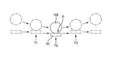
図11を参照して、打錠機21が回転プレス装置100を通過する時の挙動について詳細に説明する。
上部プレスローラー102が最下点に到達する直前に、上部プレスローラー102の外周面が上杵40の頭部43の頭頂面に接触し、下部プレスローラー107が最上点に到達する直前に、下部プレスローラー107の外周面が下杵50の頭部53の頭頂面に接触する(図11の矢印T1参照)。これにより、上杵40の杵先42と下杵50の杵先52との間に挟まれた粉末に対する加圧が開始される。以下、このタイミングを加圧開始タイミングという。
上部プレスローラー102が最下点に到達する直前に、上部プレスローラー102の外周面が上杵40の頭部43の頭頂面に接触し、下部プレスローラー107が最上点に到達する直前に、下部プレスローラー107の外周面が下杵50の頭部53の頭頂面に接触する(図11の矢印T1参照)。これにより、上杵40の杵先42と下杵50の杵先52との間に挟まれた粉末に対する加圧が開始される。以下、このタイミングを加圧開始タイミングという。
ここで、上部プレスローラー102,106の周速度が打錠機21の走行速度に等しいので、加圧開始タイミングにおいては上部プレスローラー102が上杵40の頭部43のほぼ直上から頭部43に接触し、下部プレスローラー107が下杵50の頭部53のほぼ直下から頭部53に接触する。そのため、横向きの荷重は杵40、50に殆ど作用しない。よって、粉末に無駄なく圧力が掛かり、粉末が良好に固形化する。また、圧縮成形装置1にストレスを与えずに済む。
また、加圧開始タイミングにおいて、上部プレスローラー102は最下点に近い位置で上杵40の頭部43に接触する。更に、上部プレスローラー102の外周面のうち最下部又はその近傍が上杵40の頭部43に接触し、上部プレスローラー102の外周面と上杵40の頭部43の接触部分から上部プレスローラー102の中心軸までを結ぶ面は鉛直方向に対してほぼ平行である。そのため、上部プレスローラー102と上杵40との接触部分における接線方向の分力が非常に小さく、横向きの荷重が上杵40に殆ど作用しない。よって、粉末に無駄なく圧力が掛かり、粉末が良好に固形化する。
同様に、加圧開始タイミングにおいて、下部プレスローラー107が最上点に近い位置で下杵50の頭部53に接触し、下部プレスローラー107の外周面と下杵50の頭部53の接触部分から下部プレスローラー107の中心軸までを結ぶ面は鉛直方向に対してほぼ平行である。そのため、横向きの荷重が下杵50に殆ど作用しない。
同様に、加圧開始タイミングにおいて、下部プレスローラー107が最上点に近い位置で下杵50の頭部53に接触し、下部プレスローラー107の外周面と下杵50の頭部53の接触部分から下部プレスローラー107の中心軸までを結ぶ面は鉛直方向に対してほぼ平行である。そのため、横向きの荷重が下杵50に殆ど作用しない。
上述のように、加圧開始タイミングにおいて、上部プレスローラー102が上杵40の頭部43のほぼ直上から頭部53の頭頂面に接触し、下部プレスローラー107が下杵50の頭部53の直下から頭部53の頭頂面に接触するので、頭部43,53の頭頂面を上杵40及び下杵50の軸線に対して垂直な平坦面とすることができる。頭部43,53の頭頂面が平坦面であれば、プレスローラー102,107から頭部43,53の頭頂面への荷重によっても接線方向の分力が殆ど発生しない。そのため、横向きの荷重が杵40,50に殆ど作用しない。
その後、上部プレスローラー102が最下点に到達するとともに、下部プレスローラー107が最上点に到達する(図11の矢印T2参照)。その直後に、上部プレスローラー102の外周面が上杵40の頭部43の頭頂面から離れ、下部プレスローラー107の外周面が下杵50の頭部53の頭頂面から離れる(図11の矢印T3参照)。これにより、粉末に対する加圧が終了する。以下、このタイミングを加圧終了タイミングという。
加圧開始タイミングから加圧終了タイミングまでの間、加圧アクチュエータ110によって一定の圧力が杵40,50から粉末に掛かる。これは、加圧アクチュエータ110が荷重一定となるように制御されているためである。
加圧開始タイミングから加圧終了タイミングまでの間、上部プレスローラー102がアッパーホイール101の軸回りの周方向に移動するともに、上杵40が下流へ移動する。上部プレスローラー102が上杵40の頭部43に圧接されているので、上杵40の頭部43及び上部プレスローラー102の移動に伴って、上部プレスローラー102と上杵40との接触部分における接線方向の荷重が発生する虞がある。しかし、上部プレスローラー102が回転軸103を中心にして回転することによって、上部プレスローラー102と上杵40の頭部43との間で滑りが発生せず、接線方向の荷重が解放される。そのため、横向きの荷重が上杵40に作用せず、粉末が良好に固形化する。
加圧開始タイミングから加圧終了タイミングまでの間、下部プレスローラー107が周方向に移動するともに、下杵50が下流へ移動する。上部プレスローラー102の場合と同様に、下部プレスローラー107が回転軸108を中心にして回転することによって、横向きの荷重が下杵50に作用しない。
6. 効果・利点
以上の実施形態には次のような効果・利点がある。
(1) 臼30、上杵40、下杵50及び直動案内機構60等を走行キャリッジ22に組み付けて、打錠機21がモジュール化されている。そのため、これら打錠機21の配列形状に自由度があり、打錠機21の軌跡に形状的な制約を受けない。従って、複数の打錠機21がオーバル形状のレール11,12に沿って配列されているような圧縮成形装置1を提供することができる。
以上の実施形態には次のような効果・利点がある。
(1) 臼30、上杵40、下杵50及び直動案内機構60等を走行キャリッジ22に組み付けて、打錠機21がモジュール化されている。そのため、これら打錠機21の配列形状に自由度があり、打錠機21の軌跡に形状的な制約を受けない。従って、複数の打錠機21がオーバル形状のレール11,12に沿って配列されているような圧縮成形装置1を提供することができる。
(2) レール11,12をオーバル形状とすることができるので、レール11,12には直線部があり、その直線部の脇に粉末供給装置90及び回転プレス装置100を配置することができる。また、レール11,12の全長を長くしつつ、レール11,12によって囲まれた領域の面積の増大を最小限に抑えることができる。レール11,12の全長を長くすることによって、粉末供給装置90や回転プレス装置100を複数レール11,12に沿って配列することもできる。粉末供給装置90や回転プレス装置100以外の装置をレール11,12の脇に配置して、その装置で各種の処理(例えば、臼30のクリーニング、錠剤のピックアップ、臼孔31への液体や固体の供給等)を行うこともできる。
(3) 臼30、上杵40、下杵50及び直動案内機構60が走行キャリッジ22に組み付けられているので、臼30、上杵40及び下杵50の同軸度を高い状態とすることができる。打錠機21の走行や動作によって臼30、上杵40及び下杵50の同軸度が低下することも抑えることができる。
(4) 直動案内機構60が臼孔31の直上や直下に設けられているのではなく、臼30の臼孔31から水平方向にずれた位置に設けられている。そのため、直動案内機構60の潤滑油が臼孔31に漏れるようなことがない。
(5) 伸縮管67,68によって直動案内機構60を塵埃や粉末から保護することができる。
(6) 上杵40の頭部43が上部ブラケット64に上面に引っ掛かっているので、上杵40の位置決めを行うことができるとともに、上部プレスローラー102が上部ブラケット64に直接圧接することを防止することができる。また、上部プレスローラー102が上杵40に直接圧接するので、粉末を適切に加圧することができる。下杵50、下部ブラケット65及び下部プレスローラー107についても同様である。
(7) レール11,12の直線部の脇に粉末供給装置90及び回転プレス装置100が配置されているので、粉末供給装置90による粉末の供給を良好に行えるとともに、回転プレス装置100による加圧も良好に行うことができる。
(8) 上杵40の頭部43がほぼ直上から上部プレスローラー102によって加圧され、下杵50の頭部53がほぼ直下から下部プレスローラー107によって加圧されるので、横向きの荷重が杵40、50に殆ど作用しない。
(9) プレスローラー102,107が杵40,50の頭部43,53により従動的に回転するものとしても、ホイール101,106が回転駆動機120によって回転駆動されるので、プレスローラー102,107を旋回させることができる。上部プレスローラー102,107が旋回するからこそ、加圧開始タイミングから加圧終了タイミングまで上部プレスローラー102と上杵40の頭部43が圧接状態で移動し、加圧開始タイミングから加圧終了タイミングまで下部プレスローラー107と下杵50の頭部53が圧接状態で移動する。そのため、加圧開始タイミングから加圧終了タイミングまで、上杵40の頭部43がほぼ直上から上部プレスローラー102によって加圧され、下杵50の頭部53がほぼ直下から下部プレスローラー107によって加圧される。
(10) 加圧アクチュエータ110による粉末の圧縮中の圧力が一定であるので、錠剤が良好に形成される。更に、プランジャー111の上下方向の変位を変位センサー114によって検出することによって、臼孔31内の粉末の圧縮状態や量等を監視することができる。また、変位センサー114はロードセル等と比較しても正確な検出を行えるので、変位センサー114の出力信号を利用して正確なフィードバック制御を行うことができる。
7. 変更例
以上、本発明を実施するための形態について説明したが、上記実施形態は本発明の理解を容易にするためのものであり、本発明を限定して解釈するためのものではない。本発明はその趣旨を逸脱することなく変更、改良され得るとともに、本発明にはその等価物も含まれる。以上の実施形態からの変更点について以下に説明する。以下に説明する各変更点を組み合わせて適用してもよい。
以上、本発明を実施するための形態について説明したが、上記実施形態は本発明の理解を容易にするためのものであり、本発明を限定して解釈するためのものではない。本発明はその趣旨を逸脱することなく変更、改良され得るとともに、本発明にはその等価物も含まれる。以上の実施形態からの変更点について以下に説明する。以下に説明する各変更点を組み合わせて適用してもよい。
上述の実施の形態では、図6に示すように保持体62が走行キャリッジ22の保持盤24に固定され、シャフト61が昇降可能である。それに対して、保持体62を設けず、シャフト61が走行キャリッジ22の保持盤24を上下に貫通するようにして保持盤24に固定されていてもよい。この場合、移動体63と同様な上部移動体が保持盤24の上側に配され、シャフト61がその上部移動体に挿入され、その上部移動体がシャフト61に沿って上下に移動可能となっている。また、上部ブラケット64がシャフト61の上端に組み付けられるのではなく、上部移動体に組み付けられている。更に、カムフォロワー77はブラケット66に設けられているのではなく、上部ブラケット64の後面に設けられている。そのため、ブラケット66も設けない。
上述の実施の形態では、図6に示すように上杵40とシャフト61が一体的に昇降し、下杵50がシャフト61とは別に昇降するものである。それに対して、下杵50とシャフト61が一体的に昇降し、上杵40がシャフト61とは別に昇降してもよい。具体的には、移動体63及びブラケット66を設けず、下部ブラケット65がシャフト61の下端部に組み付けられる。これにより、下杵50とシャフト61が一体的に昇降する。一方、移動体63と同様な上部移動体が保持盤24の上側に配され、シャフト61がその上部移動体に挿入され、その上部移動体がシャフト61に沿って上下に移動可能となっている。また、上部ブラケット64がシャフト61の上端に組み付けられるのではなく、上部移動体に組み付けられている。これにより、上杵40がシャフト61とは別に昇降する。また、カムフォロワー77は上部ブラケット64の後面に設けられている。
上述の実施の形態では、打錠機21が回転プレス装置100を通過してからその打錠機21が粉末供給装置90に到達するまでの間に、下杵50が上昇した後に下降する。それに対して、打錠機21が回転プレス装置100を通過してからその打錠機21が粉末供給装置90に到達するまでの間に、その打錠機21のカムフォロワー78が下杵動作用カム74によって引き下げられた後に後に押し上げられてもよい。これにより、打錠機21が回転プレス装置100を通過する時点で臼30の臼孔31に挿入されていた下杵50が下降した後に上昇する。下杵50が下降することによって、下杵50の杵先52が臼孔31から下へ抜けるので、成形された錠剤が臼孔31から落下する。下降後に下杵50が上昇することによって、下杵50の杵先52が臼孔31に挿入される。
上述の実施の形態では、走行用駆動装置80がチェーン駆動装置であったが、リニアモーター、スクリュー駆動装置その他の駆動装置であってもよい。例えば、図12の平面図に示すスクリュー駆動装置を走行用駆動装置80に適用してもよい。図12に示すように、リードスクリュー87がアッパーレール11の直線部11bと平行となるよう直線部11bに沿って設けられている。そして、リードスクリュー87は軸受等によって回転可能に支持されている。リードスクリュー87の外周面には螺旋状の溝88が形成されている。一方、各打錠機21のローラー支持板23の後面には摺動駒89が設けられ、これら摺動駒89が溝88に差し込まれている。モーター等の動力源によってリードスクリュー87が回転駆動されると、打錠機21が走行する。なお、リードスクリュー87と同様なリードスクリューが反対側の直線部11aに沿って設けられ、そのリードスクリューの回転によって打錠機21が走行するものとしてもよい。
上述の実施の形態では、回転プレス装置100の設置位置がアッパーレール11の直線部11bの脇であったが、アッパーレール11の円弧部11dの脇であってもよい。円弧部11dでは打錠機21が円弧状の軌跡を描くので、上部プレスローラー102が回転軸103に沿って移動可能となっていることが有効的である。つまり、加圧開始タイミングにおいて上部プレスローラー102が上杵40の頭部43に接触してから、上部プレスローラー102が最下点に至るまでの間、円弧状軌跡を描く頭部43によって上部プレスローラー102が回転軸103の方向に移動され、皿バネ104(又は皿バネ105)が圧縮される。上部プレスローラー102が最下点に至ってから、加圧終了タイミングにおいて上部プレスローラー102が上杵40の頭部43から離れるまでの間、円弧状軌跡を描く頭部43によって上部プレスローラー102が反対方向に移動し、皿バネ104(又は皿バネ105)が復元する。このような上部プレスローラー102の動きによって、上部プレスローラー102と上杵40の頭部43との間で滑りが発生せず、上部プレスローラー102及びアッパーホイール101に過負荷が掛からないようにすることができる。下側の下部プレスローラー107についても同様である。
上述の実施の形態では、レール11,12の形状がオーバル形状であるものとしたが、レール11,12の形状が閉曲線状であれば、オーバル形状に限るものではない。
1…圧縮成形装置, 10…走行ガイド, 11…アッパーレール, 11a…直線部, 11b…直線部, 11c…円弧部, 11d…円弧部, 12…ロアレール, 20…打錠機列, 21…打錠機, 22…走行キャリッジ, 23…ローラー支持盤, 24…保持盤, 24a…装着孔, 24b…保持孔, 25…走行ローラー, 26…走行ローラー, 27…走行ローラー, 28…走行ローラー, 30…臼, 31…臼孔, 34…止めねじ, 40…上杵, 41…胴部, 42…杵先, 43…頭部, 50…下杵, 51…胴部, 52…杵先, 53…頭部, 60…直動案内機構, 61…シャフト, 62…保持体, 63…移動体, 64…上部ブラケット, 65…下部ブラケット, 66…ブラケット, 67…上部伸縮管, 68…下部伸縮管, 70…打錠動作用カム, 71…上杵動作用カム, 72…帯板カム, 73…スリット部, 74…下杵動作用カム, 75…帯板カム, 76…スリット部, 77…カムフォロワー, 78…カムフォロワー, 80…走行用駆動装置, 81…モーター, 82…スプロケット, 84…ローラーチェーン, 85…定速制御路, 90…粉末供給装置, 100…回転プレス装置, 101…アッパーホイール, 102…上部プレスローラー(上部圧接部), 103…回転軸, 104…皿バネ(上部弾性部材), 105…皿バネ(上部弾性部材), 106…ロアホイール, 107…下部プレスローラー(下部圧接部), 108…回転軸, 110…加圧アクチュエータ(加圧機), 111…プランジャー, 114…変位センサー, 115…リンク部材, 116…リンク部材の右端部, 117…リンク部材の左端部, 120…回転駆動機, 121…モーター, 122…第一伝動機構, 122a…歯車, 122b…歯車, 122c…プーリー, 122d…タイミングベルト, 122e…二段プーリー, 122f…タイミングベルト, 122g…二段プーリー, 122h…タイミングベルト, 122i…プーリー, 123…第二伝動機構, 123a…プーリー, 123b…タイミングベルト, 123c…二段プーリー, 123c…二段プーリー, 123d…タイミングベルト, 123f…二段プーリー, 123g…タイミングベルト, 123i…プーリー, 124…定速制御回路
Claims (13)
- 所定のプレス位置を順次通過する複数の上杵及び前記上杵の下側にある複数の下杵をそのプレス位置において順次プレスするプレス装置であって、
前記プレス位置の上側において回転可能に設けられたアッパーホイールと、
前記アッパーホイールの周方向に沿って配列されるように前記アッパーホイールに取り付けられ、前記上杵の上端の頭部に圧接する複数の上部圧接部と、
前記プレス位置の下側において回転可能に設けられたロアホイールと、
前記ロアホイールの周方向に沿って配列されるように前記ロアホイールに取り付けられ、前記下杵の下端の頭部に圧接する複数の下部圧接部と、を備えるプレス装置。 - 前記上部圧接部が前記アッパーホイールの中心軸に対して平行な軸の回りに回転可能に前記アッパーホイールに取り付けられ、前記下部圧接部が前記ロアホイールの中心軸に対して平行な軸の回りに回転可能に前記ロアホイールに取り付けられている請求項1に記載のプレス装置。
- 前記上部圧接部がその軸回りの円柱面状に形成された外周面を有し、
前記下部圧接部がその軸回りの円柱面状に形成された外周面を有する請求項2に記載のプレス装置。 - 上部弾性部材及び下部弾性部材を更に備え、
前記上部圧接部が前記アッパーホイールの中心軸に対して平行な方向に移動可能となって前記アッパーホイールに取り付けられ、前記上部弾性部材が前記上部圧接部の移動に抗して前記上部圧接部を保持し、
前記下部圧接部が前記ロアホイールの中心軸に対して平行な方向に移動可能となって前記ロアホイールに取り付けられ、前記下部弾性部材が前記下部圧接部の移動に抗して前記下部圧接部を保持する請求項1から3の何れか一項に記載のプレス装置。 - 前記上部圧接部の隣同士の周ピッチが上記上杵の隣同士の間隔に等しく、前記下部圧接部の隣同士の周ピッチが上記下杵の隣同士の間隔に等しい請求項1から4の何れか一項に記載のプレス装置。
- 前記アッパーホイール及び前記ロアホイールを回転駆動する回転駆動機を更に備える請求項1から5の何れか一項に記載のプレス装置。
- 前記上杵が前記プレス位置を通過するタイミングに同期して、前記上部圧接部が前記プレス位置を通過するように、前記回転駆動機が前記アッパーホイールを回転駆動し、
前記下杵が前記プレス位置を通過するタイミングに同期して、前記下部圧接部が前記プレス位置を通過するように、前記回転駆動機が前記ロアホイールを回転駆動する請求項6に記載のプレス装置。 - 前記アッパーホイールの中心軸回りの前記上部圧接部の周速度が前記上杵の移動速度と等しくなるように、前記回転駆動機が前記アッパーホイールを回転駆動し、前記ロアホイールの中心軸回りの前記下部圧接部の周速度が前記下杵の移動速度と等しくなるように、前記回転駆動機が前記ロアホイールを回転駆動する請求項6又は7に記載のプレス装置。
- 前記アッパーホイールと前記ロアホイールが近づく方向の荷重を前記アッパーホイールと前記ロアホイールの少なくとも一方に付与する加圧機を更に備える請求項1から8の何れか一項に記載のプレス装置。
- 前記加圧機が一定の荷重を前記アッパーホイールと前記ロアホイールの少なくとも一方に付与する請求項9に記載のプレス装置。
- 回転可能なホイールと、
前記ホイールの中心軸からずれた位置において前記ホイールに取り付けられ、杵先で粉末を打つ杵の頭部に圧接する圧接部と、を備えるロータリープレス盤。 - 前記圧接部が前記ホイールの中心軸に対して平行な軸の回りに回転可能に前記ホイールに取り付けられている請求項11に記載のロータリープレス盤。
- 前記圧接部がその軸回りの円柱面状に形成された外周面を有する請求項12に記載のロータリープレス盤。
Priority Applications (1)
| Application Number | Priority Date | Filing Date | Title |
|---|---|---|---|
| PCT/JP2016/071017 WO2018011982A1 (ja) | 2016-07-15 | 2016-07-15 | プレス装置及びロータリープレス盤 |
Applications Claiming Priority (1)
| Application Number | Priority Date | Filing Date | Title |
|---|---|---|---|
| PCT/JP2016/071017 WO2018011982A1 (ja) | 2016-07-15 | 2016-07-15 | プレス装置及びロータリープレス盤 |
Publications (1)
| Publication Number | Publication Date |
|---|---|
| WO2018011982A1 true WO2018011982A1 (ja) | 2018-01-18 |
Family
ID=60952906
Family Applications (1)
| Application Number | Title | Priority Date | Filing Date |
|---|---|---|---|
| PCT/JP2016/071017 Ceased WO2018011982A1 (ja) | 2016-07-15 | 2016-07-15 | プレス装置及びロータリープレス盤 |
Country Status (1)
| Country | Link |
|---|---|
| WO (1) | WO2018011982A1 (ja) |
Citations (4)
| Publication number | Priority date | Publication date | Assignee | Title |
|---|---|---|---|---|
| JPH11114698A (ja) * | 1997-10-08 | 1999-04-27 | Kikusui Seisakusho Ltd | 回転式粉末圧縮成形機 |
| JPH11207500A (ja) * | 1998-01-22 | 1999-08-03 | Hata Tekkosho:Kk | 回転式粉末圧縮成型機 |
| JP2014213350A (ja) * | 2013-04-25 | 2014-11-17 | 伊藤工具株式会社 | 錠剤の製造方法 |
| JP2015534539A (ja) * | 2012-07-23 | 2015-12-03 | プロテウス デジタル ヘルス, インコーポレイテッド | 摂取可能構成要素を備える摂取可能事象マーカーを製造するための技法 |
-
2016
- 2016-07-15 WO PCT/JP2016/071017 patent/WO2018011982A1/ja not_active Ceased
Patent Citations (4)
| Publication number | Priority date | Publication date | Assignee | Title |
|---|---|---|---|---|
| JPH11114698A (ja) * | 1997-10-08 | 1999-04-27 | Kikusui Seisakusho Ltd | 回転式粉末圧縮成形機 |
| JPH11207500A (ja) * | 1998-01-22 | 1999-08-03 | Hata Tekkosho:Kk | 回転式粉末圧縮成型機 |
| JP2015534539A (ja) * | 2012-07-23 | 2015-12-03 | プロテウス デジタル ヘルス, インコーポレイテッド | 摂取可能構成要素を備える摂取可能事象マーカーを製造するための技法 |
| JP2014213350A (ja) * | 2013-04-25 | 2014-11-17 | 伊藤工具株式会社 | 錠剤の製造方法 |
Similar Documents
| Publication | Publication Date | Title |
|---|---|---|
| CN101422802B (zh) | 片材馈送设备 | |
| CN106347923B (zh) | 板材输送装置 | |
| JP2567800Y2 (ja) | ねじ軸用中間サポート装置 | |
| TWI611962B (zh) | 門懸吊裝置 | |
| JP3869115B2 (ja) | 加工機械 | |
| KR101535469B1 (ko) | 장력 유지 유닛을 구비한 와이어 구동형 리니어 이송장치 | |
| JP6499902B2 (ja) | 打錠機、打錠機列及び圧縮成形装置 | |
| JPH1128636A (ja) | 産業機械の送り装置およびこれを用いた産業機械 | |
| WO2018011982A1 (ja) | プレス装置及びロータリープレス盤 | |
| JP7241630B2 (ja) | 張力付与装置、金属製品の製造装置及び金属製品の製造方法 | |
| JP2016198795A (ja) | プレス装置及びロータリープレス盤 | |
| US2860686A (en) | Component-lead straightening machinery | |
| TW201801899A (zh) | 沖壓裝置及旋轉沖壓盤 | |
| CN106975938B (zh) | 无冲击滚珠丝杠辅助支撑装置 | |
| CN107107368B (zh) | 用于片材元件的横向定位装置 | |
| JPH10263729A (ja) | 高速プレス送りユニットのための零力ロール解除 | |
| JP5741953B2 (ja) | 抜き加工装置 | |
| KR102058551B1 (ko) | 벤딩기 및 이를 이용한 u 형 벤딩 방법 | |
| WO2017064742A1 (ja) | 直線駆動装置 | |
| JP5399135B2 (ja) | ヘミング加工装置 | |
| CN107600877A (zh) | 传送装置 | |
| KR950703479A (ko) | 버클 폴딩 머신(buckle folding machine) | |
| JPS62264897A (ja) | 押抜き装置 | |
| JP2608159B2 (ja) | プラテンプレス装置 | |
| US1529054A (en) | Blank-feeding mechanism |
Legal Events
| Date | Code | Title | Description |
|---|---|---|---|
| 121 | Ep: the epo has been informed by wipo that ep was designated in this application |
Ref document number: 16908883 Country of ref document: EP Kind code of ref document: A1 |
|
| NENP | Non-entry into the national phase |
Ref country code: DE |
|
| 122 | Ep: pct application non-entry in european phase |
Ref document number: 16908883 Country of ref document: EP Kind code of ref document: A1 |
|
| NENP | Non-entry into the national phase |
Ref country code: JP |