WO2018008507A1 - 熱電発電装置 - Google Patents
熱電発電装置 Download PDFInfo
- Publication number
- WO2018008507A1 WO2018008507A1 PCT/JP2017/023900 JP2017023900W WO2018008507A1 WO 2018008507 A1 WO2018008507 A1 WO 2018008507A1 JP 2017023900 W JP2017023900 W JP 2017023900W WO 2018008507 A1 WO2018008507 A1 WO 2018008507A1
- Authority
- WO
- WIPO (PCT)
- Prior art keywords
- side portion
- fluid
- thermal resistance
- upstream
- layer
- Prior art date
- Legal status (The legal status is an assumption and is not a legal conclusion. Google has not performed a legal analysis and makes no representation as to the accuracy of the status listed.)
- Ceased
Links
Images


Classifications
-
- F—MECHANICAL ENGINEERING; LIGHTING; HEATING; WEAPONS; BLASTING
- F01—MACHINES OR ENGINES IN GENERAL; ENGINE PLANTS IN GENERAL; STEAM ENGINES
- F01N—GAS-FLOW SILENCERS OR EXHAUST APPARATUS FOR MACHINES OR ENGINES IN GENERAL; GAS-FLOW SILENCERS OR EXHAUST APPARATUS FOR INTERNAL-COMBUSTION ENGINES
- F01N5/00—Exhaust or silencing apparatus combined or associated with devices profiting by exhaust energy
- F01N5/02—Exhaust or silencing apparatus combined or associated with devices profiting by exhaust energy the devices using heat
-
- H—ELECTRICITY
- H02—GENERATION; CONVERSION OR DISTRIBUTION OF ELECTRIC POWER
- H02N—ELECTRIC MACHINES NOT OTHERWISE PROVIDED FOR
- H02N11/00—Generators or motors not provided for elsewhere; Alleged perpetua mobilia obtained by electric or magnetic means
-
- H—ELECTRICITY
- H10—SEMICONDUCTOR DEVICES; ELECTRIC SOLID-STATE DEVICES NOT OTHERWISE PROVIDED FOR
- H10N—ELECTRIC SOLID-STATE DEVICES NOT OTHERWISE PROVIDED FOR
- H10N10/00—Thermoelectric devices comprising a junction of dissimilar materials, i.e. devices exhibiting Seebeck or Peltier effects
- H10N10/10—Thermoelectric devices comprising a junction of dissimilar materials, i.e. devices exhibiting Seebeck or Peltier effects operating with only the Peltier or Seebeck effects
- H10N10/13—Thermoelectric devices comprising a junction of dissimilar materials, i.e. devices exhibiting Seebeck or Peltier effects operating with only the Peltier or Seebeck effects characterised by the heat-exchanging means at the junction
-
- H—ELECTRICITY
- H10—SEMICONDUCTOR DEVICES; ELECTRIC SOLID-STATE DEVICES NOT OTHERWISE PROVIDED FOR
- H10N—ELECTRIC SOLID-STATE DEVICES NOT OTHERWISE PROVIDED FOR
- H10N10/00—Thermoelectric devices comprising a junction of dissimilar materials, i.e. devices exhibiting Seebeck or Peltier effects
- H10N10/10—Thermoelectric devices comprising a junction of dissimilar materials, i.e. devices exhibiting Seebeck or Peltier effects operating with only the Peltier or Seebeck effects
- H10N10/17—Thermoelectric devices comprising a junction of dissimilar materials, i.e. devices exhibiting Seebeck or Peltier effects operating with only the Peltier or Seebeck effects characterised by the structure or configuration of the cell or thermocouple forming the device
-
- Y—GENERAL TAGGING OF NEW TECHNOLOGICAL DEVELOPMENTS; GENERAL TAGGING OF CROSS-SECTIONAL TECHNOLOGIES SPANNING OVER SEVERAL SECTIONS OF THE IPC; TECHNICAL SUBJECTS COVERED BY FORMER USPC CROSS-REFERENCE ART COLLECTIONS [XRACs] AND DIGESTS
- Y02—TECHNOLOGIES OR APPLICATIONS FOR MITIGATION OR ADAPTATION AGAINST CLIMATE CHANGE
- Y02T—CLIMATE CHANGE MITIGATION TECHNOLOGIES RELATED TO TRANSPORTATION
- Y02T10/00—Road transport of goods or passengers
- Y02T10/10—Internal combustion engine [ICE] based vehicles
- Y02T10/12—Improving ICE efficiencies
Definitions
- thermoelectric generator that converts thermal energy into electric energy by the Seebeck effect.
- the thermoelectric power generation device of Patent Document 1 includes a thermal stress relaxation material interposed between a high temperature side surface of a module composed of a thermoelectric conversion element and a high temperature side member having a high temperature medium passage.
- the thermal stress relaxation material is made of conductive graphite.
- the thermal stress relieving material is a sheet-like member formed integrally with strip-like graphite materials arranged in parallel on one plane.
- the thermal stress relaxation material interposed between the high-temperature medium and the high-temperature side surface of the thermoelectric conversion element has no interlayer in the direction orthogonal to the front and back surfaces, so that the heat conduction in the orthogonal direction is good.
- the thermal resistance between the high temperature medium and the high temperature side surface of the thermoelectric conversion element can be reduced.
- the thermal stress relaxation material of Patent Document 1 does not consider how heat is transmitted in the flow direction of the high-temperature medium.
- the thermal stress relaxation material of Patent Document 1 has sufficient room for improvement in order to efficiently generate power in the entire flow direction of the high-temperature medium that applies heat to the high-temperature side surface of the thermoelectric conversion element.
- an object of the present disclosure is to provide a thermoelectric power generation apparatus that performs efficient power generation.
- thermoelectric power generation device includes a first fluid passage through which a first fluid flows, and a second fluid that is hotter than the first fluid and discharged from an engine.
- a first fluid passage a thermoelectric generator having a thermoelectric conversion element and generating electricity by a temperature difference between the one side and the other side, and the first fluid passage and the one side,
- a low temperature side member forming at least a part of a heat transfer path between the fluid and the one side part, and interposed between the second fluid passage and the other side part, and between the second fluid and the other side part.
- a high-temperature side member that forms at least a part of the heat transfer path, and the high-temperature side member has an upstream side portion and an upstream side portion that are provided upstream with thermal resistance to heat that moves along the flow direction of the second fluid. Configured so that one is larger than the other at the downstream side provided downstream It has been.
- thermoelectric generator when the upstream side portion of the high temperature side member is configured to have a smaller thermal resistance in the flow direction of the second fluid than the downstream side portion, a thermoelectric power in a range corresponding to the upstream side portion is obtained.
- the conversion element since the degree of temperature decrease toward the downstream is small, high-temperature exhaust heat can be recovered. As a result, the amount of power generation can be improved in the thermoelectric conversion element in the range corresponding to the upstream side portion. Further, in the thermoelectric conversion element in the range corresponding to the downstream side portion, the temperature decrease degree is large toward the downstream, so that the low-temperature exhaust heat can be recovered, and in the thermoelectric conversion element in the range corresponding to the downstream side portion, The amount of power generation can be improved.
- thermoelectric conversion element corresponding to the upstream of the side portion tends to be high.
- the power generation amount can be improved in the upstream thermoelectric conversion element.
- the temperature decrease degree toward the downstream is small, so that the temperature difference between the elements in the flow direction can be increased.
- the amount of power generation can be improved in the thermoelectric conversion element in the range corresponding to the downstream side portion.
- thermoelectric generator of 1st Embodiment a cooling water, and waste gas.
- thermoelectric power generator of 1st Embodiment It is the figure which showed the structure of the thermoelectric generator of 1st Embodiment. It is the perspective view which showed the thermal resistance adjustment layer of 1st Embodiment.
- thermoelectric generator of a 1st embodiment it is a graph which showed temperature distribution of an exhaust gas flow direction about each of element high temperature end, element low temperature end, and exhaust gas.
- thermoelectric generator of a 2nd embodiment it is a graph which showed temperature distribution of an exhaust gas flow direction about each of a device high temperature end, a device low temperature end, and exhaust gas. It is the figure which showed the structure of the thermoelectric power generating apparatus of 3rd Embodiment. It is the figure which showed the structure of the thermoelectric power generating apparatus of 4th Embodiment. It is the perspective view which showed the thermal resistance adjustment layer of 4th Embodiment. It is the perspective view which showed the thermal resistance adjustment layer of 5th Embodiment. It is the perspective view which showed the thermal resistance adjustment layer of 6th Embodiment.
- thermoelectric generator 1 is a device that converts thermal energy into electric energy by the Seebeck effect using a temperature difference between the exhaust gas as the second fluid discharged from the engine 20 and the first fluid that is lower in temperature than the exhaust gas. is there.
- a temperature difference is given between the low-temperature side part 10a that is one side and the high-temperature side part 10b that is the other side in the thermoelectric power generation part 10 having a thermoelectric conversion element
- the thermoelectric power generation apparatus 1 generates a potential difference and electrons are generated. Electricity is generated using the flowing phenomenon.
- Any fluid capable of giving a temperature difference from the exhaust gas can be adopted as the first fluid. In this embodiment, a case where cooling water of an automobile engine 20 is used as an example of an arbitrarily selectable low-temperature fluid will be described.
- An engine 20 which is an internal combustion engine is connected to an intake pipe for sucking combustion air and an exhaust pipe 3 for discharging exhaust gas after combustion.
- a throttle valve whose opening is variable according to the amount of depression of an accelerator pedal provided in the vehicle is provided in the intake pipe.
- the engine 20 is controlled for optimal operation by an engine control device.
- An engine speed signal, a throttle valve opening signal, a vehicle speed signal, and the like are input to the engine control device.
- the engine control device stores in advance a control map in which the fuel injection amount is associated with the engine speed signal and the throttle valve opening signal.
- the engine control device controls the fuel injection amount required at a predetermined timing on the intake pipe side based on the control map.
- the engine control device is connected to the control device 5 of the thermoelectric generator 1 so as to be able to communicate with each other for transmission and reception of signals.
- the cooling water circuit 2 is connected to the engine 20.
- the cooling water circuit 2 is a circuit through which cooling water in the engine 20 circulates to cool the engine 20. Cooling water passes through the radiator 21 from the outlet 20b through the water pump 24 and circulates through the inlet 20a.
- the water pump 24 is, for example, an engine-driven pump that operates by receiving the driving force of the engine 20. Since the cooling water circulating through the cooling water circuit 2 is cooled by the heat radiation of the radiator 21, the operating temperature of the engine 20 can be controlled appropriately.
- the cooling water circuit 2 is provided with a bypass passage 26 that bypasses the radiator 21 and a thermostat 22 that adjusts the flow rate of the cooling water to the radiator 21 side or the bypass passage 26 side.
- a bypass passage 26 that bypasses the radiator 21
- a thermostat 22 that adjusts the flow rate of the cooling water to the radiator 21 side or the bypass passage 26 side.
- the cooling water circuit 2 is provided with a heater core 23 and a heater hot water circuit 25 forming a part of the cooling water circuit 2 so as to be in parallel with the radiator 21.
- the heater core 23 is a heat exchanger for a heating device that heats air for air conditioning using cooling water as a heat source.
- the thermoelectric generator 1 includes a thermoelectric generator 10 and a controller 5 that controls the operation of the thermoelectric generator 10.
- the thermoelectric power generation unit 10 is provided with a branch passage 31 that is a second fluid passage and a circulation passage 27 that is a first fluid passage with respect to the thermoelectric conversion element 100 that generates power using the Seebeck effect. It is configured.
- the branch passage 31 constitutes a passage formed so as to branch from the exhaust pipe 3 of the engine 20 and merge with the exhaust pipe 3 again, and is configured such that a part of the exhaust gas is diverted.
- the branch passage 31 comes into contact with the thermoelectric conversion element 100 or the high temperature side portion 10 b that is the other side surface of the thermoelectric power generation unit 10, and the exhaust gas becomes a high temperature side heat source of the thermoelectric conversion element 100.
- An on-off valve 30 for opening and closing the branch passage 31 is provided on the upstream side of the exhaust gas with respect to the thermoelectric conversion element 100 in the branch passage 31.
- the circulation passage 27 is a passage closer to the engine 20 than the bypass passage 26, and is a passage connecting the thermostat 22 and the inlet portion 20 a on the downstream side of the radiator 21.
- the circulation passage 27 is in contact with the thermoelectric conversion element 100 or the low temperature side portion 10 a that is one side surface of the thermoelectric power generation unit 10.
- the cooling water flowing through the thermostat 22 from the bypass passage 26 or the cooling water passing through the radiator 21 and flowing through the thermostat 22 is supplied to the thermoelectric conversion element 100 side, and this cooling water becomes a low temperature side heat source of the thermoelectric conversion element 100.
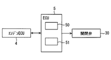
- the control device 5 includes a device such as a microcomputer that operates according to a program as a main hardware element. As illustrated in FIG. 2, the control device 5 includes an interface unit 50 (hereinafter also referred to as an I / F unit 50) to which various devices and various sensors are connected, and an arithmetic processing unit 51.
- the arithmetic processing unit 51 performs determination processing and arithmetic processing according to a predetermined program using information acquired from various sensors and various measuring devices through the I / F unit 50 and various data stored in the storage unit.
- the storage unit includes a writable storage medium, and temporarily stores information based on the signal output from each detector in the storage medium.
- the storage unit is a non-transitory tangible storage medium.
- the arithmetic processing unit 51 is a determination unit in the control device 5.
- the I / F unit 50 operates various devices based on the determination result and the calculation result by the calculation processing unit 51. Therefore, the I / F unit 50 is an input unit and a control output unit in the control device 5.
- the control device 5 may be integrated with the engine control device 4 and constitute a part of the engine control device.
- the I / F unit 50 acquires engine speed, engine load information, and the like from the engine control device as engine information signals.
- the engine load information is a torque value of the engine 20, for example.
- the arithmetic processing unit 51 performs arithmetic processing on various engine information signals from the engine control device according to a preset program.
- the control device 5 controls the on-off valve 30 and the like based on the calculation result by the calculation processing unit 51.
- the control device 5 stores in advance a shaft torque map, a cooling loss heat amount map of the engine 20, a water flow rate map of the engine 20, a reference heat release amount map of the radiator 21, an opening degree map of the on-off valve 30, and various arithmetic expressions. .
- the control device 5 controls the opening degree of the on-off valve 30 based on these maps and arithmetic expressions.
- the I / F unit 50 operates devices such as the on-off valve 30 based on the calculation result by the calculation processing unit 51.
- the I / F unit 50 is connected to a terminal device serving as a user interface, such as a control panel and a portable terminal. The user can check the current driving state output from the I / F unit 50 through the display screen of the control panel, the terminal device, or the like.
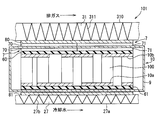
- the configuration of the thermoelectric generator 1 will be described with reference to FIGS. 3 and 4.
- the thermoelectric generator 1 includes a first fluid passage, a second fluid passage, a thermoelectric power generation unit 10, a low temperature side member interposed between the first fluid passage and the low temperature side portion 10a, and the second fluid passage.
- a high temperature side member interposed between the other side portion.
- the low temperature side member is a component that forms at least a part of the heat transfer path between the first fluid and the low temperature side portion 10 a, and is, for example, the heat transfer layer 81 and the insulating layer 61.
- the high temperature side member is a component that forms at least a part of the heat transfer path between the second fluid and the high temperature side portion 10b, and is, for example, the heat transfer layer 80, the thermal resistance adjustment layer 7, and the insulating layer 60.
- the low temperature side portion 10a and the high temperature side portion 10b have conductivity and constitute an electrode portion that electrically connects the thermoelectric conversion elements 100 adjacent in the flow direction of the exhaust gas.
- the circulation path 27 side and the branch path 31 side are alternately connected to each other so that the plurality of thermoelectric conversion elements 100 included in the thermoelectric power generation unit 10 are connected in series.
- An insulating layer 61 that insulates the electrode portion from the electrode portion is provided on the first fluid passage side of the low temperature side portion 10a.
- the insulating layer 61 is a thin plate-like member having thermal conductivity and electrical insulation, and is in contact with all of the plurality of electrode portions arranged along the exhaust gas flow direction.
- a heat transfer layer 81 having thermal conductivity is provided on the first fluid passage side of the insulating layer 61.
- the heat transfer layer 81 is a thin plate-like member that is sandwiched between the low-temperature passage member 27a that forms the circulation passage 27 therein and the insulating layer 61 and is in contact with both surfaces.
- the insulating layer 61 insulates the low temperature side portion 10a and the heat transfer layer 81 from each other.
- the low-temperature passage member 27a, the heat transfer layer 81, the insulating layer 61, and the thermoelectric conversion element 100 are in close contact with each other without forming an air layer and are integrally fixed.
- a fin 27b extending in the flow direction of the exhaust gas is provided as an accelerating portion that promotes heat transfer.
- the fins 27 b are members that can promote heat transfer from the low-temperature fluid flowing through the circulation passage 27 to the heat transfer layer 81.
- An insulating layer 60 that insulates the electrode part from the electrode part is provided on the second fluid passage side of the high temperature side part 10b.
- the insulating layer 60 is a thin plate-like member having thermal conductivity and electrical insulation, and is in contact with all of the plurality of electrode portions arranged along the exhaust gas flow direction.
- a heat resistance adjusting layer 7 having thermal conductivity is provided on the second fluid passage side of the insulating layer 60.
- the thermal resistance adjustment layer 7 is a member including a material such as metal or graphite.
- the thermal resistance adjusting layer 7 is preferably made of a material having a low stress relaxation rate, and can suppress a decrease in sealing performance due to a decrease in fixing force, thereby allowing close contact between each portion between the high temperature passage member 310 and the high temperature side portion 10b. Can maintain sex.
- the thermal resistance adjusting layer 7 is preferably made of a material that can also function as a thermal stress relaxation member such as graphite.
- the thermal resistance adjusting layer 7 is a member that is provided between the second fluid passage and the high temperature side portion 10b and constitutes a part of a heat path that moves between the second fluid and the high temperature side portion 10b. . Therefore, the heat of the second fluid moves to the high temperature side portion 10b through the thermal resistance adjusting layer 7.
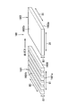
- the thermal resistance adjusting layer 7 is configured such that the thermal resistance to heat moving along the flow direction of the second fluid is different between the upstream side portion and the downstream side portion.
- the thermal resistance adjustment layer 7 includes an upstream adjustment layer 70 provided upstream and a downstream adjustment layer 71 provided downstream of the upstream adjustment layer 70. That is, the heat resistance adjusting layer 7 is configured to include at least two members having a difference in heat transfer rate along the flow direction of the exhaust gas.
- the thermal resistance adjustment layer 7 is configured such that one of the upstream adjustment layer 70 and the downstream adjustment layer 71 has a higher thermal resistance to heat moving along the flow direction of the second fluid than the other. .
- the thermal resistance adjustment layer 7 is configured such that the thermal resistance in the downstream adjustment layer 71 is greater than the thermal resistance in the upstream adjustment layer 70.
- a heat transfer layer 80 having heat conductivity is provided on the second fluid passage side of the heat resistance adjusting layer 7.
- the heat transfer layer 80 is a thin plate-like member that is sandwiched between the high-temperature passage member 310 that forms the branch passage 31 therein and the heat resistance adjusting layer 7 and is in contact with the surfaces of both.
- the insulating layer 60 insulates the high temperature side portion 10b from the thermal resistance adjusting layer 7 and the heat transfer layer 80.
- the high-temperature passage member 310, the heat transfer layer 80, the heat resistance adjusting layer 7, the insulating layer 60, and the thermoelectric conversion element 100 are in close contact with each other without forming an air layer, and are fixed integrally.
- fins 311 extending in the flow direction of the exhaust gas are provided as promotion portions that promote heat transfer.
- the fin 311 is a member that can promote heat transfer from the high-temperature fluid flowing through the branch passage 31 to the heat transfer layer 80.
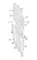
- the upstream adjustment layer 70 is configured by integrally joining a plurality of elongated graphite pieces 700 extending along the flow direction of the second fluid.
- the plurality of graphite pieces 700 are integrated in a state where the adjacent pieces are joined to each other, thereby forming the upstream adjustment layer 70.
- the graphite piece 700 has good thermal conductivity in each of the thickness direction, the longitudinal direction, and the short direction. Therefore, each of the graphite pieces 700 has good heat in both the direction D2 orthogonal to both the one side surface 70a and the other side surface 70b, the exhaust gas flow direction D1, and the direction D3 orthogonal to both the direction D2 and the direction D1. Demonstrate conductivity.
- the thermal resistance in the direction D3 is greater than the thermal resistance in each of the direction D2 and the direction D1.
- the downstream adjustment layer 71 is formed by integrally joining a plurality of elongated graphite pieces 710 extending along the direction D3.
- the plurality of graphite pieces 710 are integrated with each other adjacent to each other to form the downstream adjustment layer 71.
- the graphite piece 710 has good thermal conductivity in each of the thickness direction, the longitudinal direction, and the short direction. Therefore, each of the graphite pieces 710 has good thermal conductivity in any of the direction D2 orthogonal to both the one side surface 71a and the other side surface 71b, the flow direction D1, and the direction D3 orthogonal to both the direction D2 and the direction D1. Demonstrate.
- the thermal resistance in the flow direction D1 is larger than the thermal resistance in each of the direction D2 and the direction D3.
- the downstream adjusting layer 71 whose thermal resistance in the flow direction D1 is larger than that of the upstream adjusting layer 70 is configured by arranging a plurality of graphite pieces 710 along the flow direction D1.
- the upstream adjusting layer 70 whose thermal resistance in the flow direction D ⁇ b> 1 is smaller than the downstream adjusting layer 71 is formed by joining a plurality of graphite pieces 700 each having an elongated shape in the flow direction D ⁇ b> 1. It is configured integrally in a state.
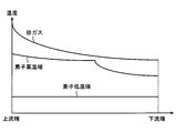
- the horizontal axis indicates the displacement in the flow direction D1.
- the vertical axis indicates the temperature of each part described above.
- the exhaust gas has the highest temperature at the upstream end, the temperature rapidly decreases from the upstream end, and gradually decreases toward the downstream end.
- the low temperature side part 10a in the thermoelectric conversion element 100 exhibits a substantially constant temperature in the flow direction.
- the temperature change rate in the exhaust gas flow direction in the high temperature side portion 10 b of the thermoelectric conversion element 100 is different between a range corresponding to the upstream adjustment layer 70 and a range corresponding to the downstream adjustment layer 71.
- the thermal resistance in the flow direction D1 is small.
- the heat absorbed on the upstream side smoothly conducts to the downstream side, so that the temperature on the downstream side is the upstream side.
- the temperature does not drop greatly with respect to the temperature. Therefore, as shown in FIG.
- thermoelectric conversion element 100 of the range corresponding to the upstream adjustment layer 70 can be raised.
- the joining surface of the graphite piece portion 710 and the graphite piece portion 710 is aligned in the flow direction D1, so that the thermal resistance in the flow direction D1 is large.
- the heat absorbed on the upstream side does not smoothly conduct to the downstream side, so that the heat tends to stagnate on the upstream side and the temperature on the downstream side is upstream.
- the temperature greatly decreases with respect to the temperature. Accordingly, as shown in FIG. 5, the high temperature side portion 10 b has a large temperature decrease degree from the upstream to the downstream, and therefore, low temperature exhaust heat can be recovered.
- thermoelectric conversion element 100 of the range corresponding to the downstream adjustment layer 71 the electric power generation amount with respect to low-temperature exhaust heat can be raised.
- the thermal resistance adjusting layer 7 is effective in terms of the amount of power generation in the thermoelectric conversion element 100 in a range corresponding to each of the upstream adjusting layer 70 and the downstream adjusting layer 71.
- the thermoelectric generator 1 includes a first fluid passage through which a first fluid flows, a second fluid passage through which a second fluid discharged from the engine 20 at a temperature higher than that of the first fluid, and a thermoelectric conversion element 100. And a thermoelectric power generation unit 10 that generates power by a temperature difference between the portion 10a and the high temperature side portion 10b.
- the thermoelectric generator 1 includes at least one of a heat transfer path between the low temperature side member forming at least a part of the heat transfer path between the first fluid and the low temperature side part 10a and the second fluid and the high temperature side part 10b. And a high temperature side member forming a part.
- the high temperature side member is configured such that the thermal resistance to heat moving along the flow direction D1 of the second fluid is greater in the downstream side portion provided downstream than the upstream side portion provided upstream. .
- thermoelectric conversion element 100 in the range corresponding to the upstream side portion According to the configuration in which the thermal resistance in the flow direction D1 of the second fluid is smaller in the upstream side portion of the high temperature side member than in the downstream side portion, heat is easily transmitted downstream in the thermoelectric conversion element 100 in the range corresponding to the upstream side portion.
- the degree of temperature decrease toward the downstream is small.
- the thermoelectric conversion element 100 in the range corresponding to the upstream side portion can recover high-temperature exhaust heat. Therefore, the thermoelectric conversion element 100 in the range corresponding to the upstream side portion has an effect of increasing the power generation amount.
- the downstream heat transmission is not smooth in the downstream side portion as compared with the upstream side portion, and thus the degree of temperature decrease is large toward the downstream side.
- thermoelectric conversion element 100 in the range corresponding to the downstream side portion has an effect of increasing the amount of power generation with respect to low temperature exhaust heat.
- efficient power generation can be realized.
- the high temperature side member is a thermal resistance adjustment layer 7 provided between the second fluid passage and the high temperature side portion 10b and formed of a material containing graphite.
- the upstream side adjusting layer 70 and the downstream side adjusting layer 71 having the larger thermal resistance in the flow direction D ⁇ b> 1 have a plurality of elongated graphite pieces 710 arranged along the flow direction D ⁇ b> 1. It is constituted by. According to this, a joining surface or a gap is formed between the adjacent graphite piece portions 710 and the graphite piece portions 710 in the adjustment layer having the higher thermal resistance. For this reason, thermal resistance is generated when heat moves between adjacent graphite pieces 710. Therefore, by arranging a plurality of graphite piece portions 710 at intervals or by laminating them together, it is possible to configure an adjustment layer having a higher thermal resistance without adopting a complicated structure.
- the plurality of graphite pieces 710 are integrally formed in a state where the adjacent pieces are joined to each other. According to this, since the bonding surface is formed between the adjacent graphite piece portions 710 and the graphite piece portions 710 in the adjustment layer having the larger thermal resistance, the heat is generated between the adjacent graphite piece portions 710. Thermal resistance is generated when moving. Therefore, by laminating a plurality of graphite piece portions 710 integrally, an adjustment layer having a stable shape and a higher thermal resistance can be configured.
- the upstream adjusting layer 70 having the smaller thermal resistance is integrally formed with a plurality of elongated graphite pieces 700 in the flow direction D1 joined together.
- the downstream side adjustment layer 71 having the larger thermal resistance and the upstream side adjustment layer 70 having the smaller thermal resistance can be manufactured in the same shape and configuration, and installed by changing the orientation.
- the upstream adjustment layer 70 and the downstream adjustment layer 71 that exhibit different functions can be provided. Therefore, it can contribute to reducing the manufacturing cost of the thermal resistance adjusting layer 7.
- the thermal resistance adjustment layer 107 will be described with reference to FIGS. 6 and 7.
- the second embodiment differs from the first embodiment only in the thermal resistance adjustment layer 107.
- the thermal resistance adjustment layer 107 is another form of the thermal resistance adjustment layer 7 of the first embodiment.
- the configuration, processing, action, and effect that are not particularly described in the second embodiment are the same as those in the first embodiment, and differences from the first embodiment will be described below.
- the thermal resistance adjusting layer 107 is configured so that the thermal resistance against heat moving along the flow direction D1 is different between the upstream side portion and the downstream side portion.
- the thermal resistance adjustment layer 107 includes an upstream adjustment layer 170 provided upstream and a downstream adjustment layer 171 provided downstream from the upstream adjustment layer 170. That is, the thermal resistance adjusting layer 107 is configured to include at least two members having a difference in heat transfer rate along the flow direction of the exhaust gas.
- the thermal resistance adjustment layer 107 is configured such that the thermal resistance in the upstream adjustment layer 170 is larger than the thermal resistance in the downstream adjustment layer 171.
- the downstream adjustment layer 171 is configured by integrally joining a plurality of elongated graphite pieces 700 extending along the flow direction D1.
- the plurality of graphite pieces 700 are integrated in a state where the adjacent pieces are joined to each other, thereby forming the downstream adjustment layer 171.
- the upstream adjustment layer 170 is configured by integrally joining a plurality of elongated graphite pieces 710 extending along the direction D3.
- the plurality of graphite pieces 710 are integrated with each other adjacent to each other to form the upstream adjustment layer 170. Since the plurality of graphite pieces 710 forming the upstream adjustment layer 170 are arranged along the flow direction D1, they form a joint surface aligned along the flow direction D1. For this reason, in the upstream adjustment layer 170, the thermal resistance in the flow direction D1 is larger than the thermal resistance in each of the direction D2 and the direction D3.
- the upstream adjustment layer 170 in which the thermal resistance in the flow direction D1 is larger than that in the downstream adjustment layer 171 is configured by arranging a plurality of graphite pieces 700 along the flow direction D1.
- the downstream adjusting layer 171 whose thermal resistance in the flow direction D1 is smaller than that of the upstream adjusting layer 170 is formed by joining a plurality of graphite pieces 700 each having an elongated shape in the flow direction D1. It is configured integrally in a state.
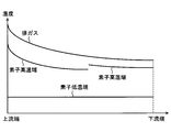
- the temperature distribution in the exhaust gas flow direction of each of the element high temperature end, the element low temperature end, and the exhaust gas in the thermoelectric generator will be described with reference to the graph of FIG.
- the horizontal axis indicates the displacement in the flow direction D1
- the vertical axis indicates the temperature of each part described above.
- the temperature change rate in the exhaust gas flow direction at the high temperature side portion 10b of the thermoelectric conversion element 100 differs between a range corresponding to the upstream adjustment layer 170 and a range corresponding to the downstream adjustment layer 171.
- the thermal resistance in the flow direction D1 is large.
- the heat absorbed on the upstream side does not smoothly conduct to the downstream side, so the heat tends to stagnate on the upstream side and the temperature on the downstream side is upstream.
- the temperature greatly decreases with respect to the temperature.
- thermoelectric conversion element 100 corresponding to the upstream side of the upstream adjustment layer 170 tends to be high in the high temperature side portion 10 b. Thereby, there exists an effect which raises the electric power generation amount in the thermoelectric conversion element 100 located upstream.
- the thermal resistance in the flow direction D1 is small.
- the heat absorbed on the upstream side is easily conducted to the downstream side smoothly, so the downstream temperature is larger than the upstream temperature. It does not decline. Therefore, as shown in FIG. 7, in the high temperature side portion 10b, since the degree of temperature decrease from the upstream to the downstream is small, a large amount of exhaust heat of the high temperature fluid can be recovered on the downstream side. Thereby, the electric power generation amount in the whole thermoelectric conversion element 100 of the range corresponding to the downstream adjustment layer 171 can be raised.
- the thermal resistance adjustment layer 107 is effective in terms of the amount of power generation in the thermoelectric conversion element 100 in the range corresponding to each of the upstream adjustment layer 170 and the downstream adjustment layer 171.
- the high temperature side member is configured such that the thermal resistance to heat moving along the second fluid flow direction D1 is greater in the upstream side than in the downstream side. ing.
- thermoelectric conversion element 100 According to the configuration in which the upstream side portion of the high temperature side member has a larger thermal resistance in the flow direction D1 than the downstream side portion, the heat is stagnant in the upstream side portion so that it does not easily flow toward the downstream side. The temperature of the thermoelectric conversion element 100 is likely to rise. For this reason, the upstream thermoelectric conversion element 100 has an effect of increasing the power generation amount. Furthermore, in the thermoelectric conversion element 100 in a range corresponding to the downstream side portion, heat is easily transmitted to the downstream side, so that the degree of temperature decrease toward the downstream side is small. For this reason, it becomes possible to enlarge the high-low temperature difference of the thermoelectric conversion element 100 over the flow direction D1.
- thermoelectric conversion element 100 the temperature difference between the high temperature side portion 10b and the low temperature side portion 10ba is large, and this temperature difference does not decrease greatly on the downstream side in the flow direction D1. Thereby, there exists an effect which raises electric power generation amount in the thermoelectric conversion element 100 of the range corresponding to a downstream side part. As described above, according to the thermoelectric generator 1, efficient power generation can be realized.
- thermoelectric generator 101 (Third embodiment) A thermoelectric generator 101 according to a third embodiment will be described with reference to FIG. Compared to the thermoelectric generator 1 described above, the thermoelectric generator 101 includes a thermoelectric generator 10, an insulating layer 60, an insulating layer 61, a thermal resistance adjusting layer 7 from the thermoelectric generator, and the like inside the case 9. Is different.
- the configuration, processing, operation, and effects that are not particularly described in the third embodiment are the same as those in the above-described embodiment, and differences from the above-described embodiment will be described below.
- the inside of the case 9 is preferably set to a vacuum state.
- the case 9 has a structure in which the thermal resistance adjusting layer 7, the insulating layer 60, the high temperature side portion 10b, the thermoelectric conversion element 100, the low temperature side portion 10a, and the insulating layer 61 are arranged in this order from the high temperature fluid passage side to the low temperature fluid passage side. Built in one. Therefore, the case 9 holds the integrated structure in a state in which adhesion is maintained so that no gap is generated between the respective parts.
- a heat transfer layer 80 is interposed between the outer surface of the case 9 in the range corresponding to the insulating layer 61 and the low-temperature passage member 27a, and the outer surface of the case 9 in the range corresponding to the thermal resistance adjusting layer 7 Between the high temperature passage member 310, the heat transfer layer 80 and the thermal resistance adjusting layer 7 are interposed.
- the case 9, the thermal resistance adjusting layer 7, the heat transfer layer 80, and the high temperature passage member 310 are integrated in a state in which adhesion is ensured so that no gap is generated between the respective parts.
- the case 9, the heat transfer layer 81, and the low-temperature passage member 27a are integrated in a state in which adhesion is ensured so that no gap is generated between the respective parts.
- thermoelectric generator 201 having an insulating layer 160 having different thermal resistance in the flow direction D1 between the upstream side portion and the downstream side portion will be described with reference to FIGS. 9 and 10.
- the configuration, processing, operation, and effects not particularly described in the fourth embodiment are the same as those in the first embodiment, and differences from the first embodiment will be described below.
- the insulating layer 160 is configured such that the thermal resistance to heat moving along the flow direction D1 is different between the upstream side portion and the downstream side portion.
- the insulating layer 160 includes an upstream layer 1601 provided upstream and a downstream layer 1602 provided downstream from the upstream layer 1601. That is, the insulating layer 160 includes at least two members having different heat transfer rates along the flow direction of the exhaust gas.
- the insulating layer 160 is configured such that the thermal resistance in the flow direction D1 in the upstream layer 1601 is greater than the thermal resistance in the flow direction D1 in the downstream layer 1602.
- the insulating layer 160 is made of the same material as the insulating layer 60.
- the high-temperature passage member 310, the heat transfer layer 80, the graphite layer 407, the insulating layer 160, and the thermoelectric conversion element 100 are in close contact with each other without forming an air layer and are integrally fixed.
- the graphite layer 407 is a thin plate-like member that is formed of a material containing graphite and is provided so as to fill the space between the heat transfer layer 80 and the insulating layer 160.
- the upstream layer 1601 is configured by arranging a plurality of elongated pieces 1600 extending along the direction D3 at intervals along the flow direction D1. Each of the pieces 1600 has thermal conductivity in both the direction D2 orthogonal to both the one side surface 1601a and the other side surface 1601b, the flow direction D1, and the direction D3 orthogonal to both the direction D2 and the direction D1.
- the thermal resistance of the upstream layer 1601 in the flow direction D1 in which the plurality of pieces 1600 is arranged is changed in the direction D3 that is the longitudinal direction of the piece 1600 and in the thickness direction. It becomes larger than a certain direction D2.
- the upstream layer 1601 whose thermal resistance in the flow direction D1 is larger than that of the downstream layer 1602 is configured by arranging a plurality of pieces 1600 along the flow direction D1.
- the downstream layer 1602 whose thermal resistance in the flow direction D1 is smaller than that of the upstream layer 1601 is a thin plate-like member having a volume equivalent to that of the upstream layer 1601.
- the downstream layer 1602 has thermal conductivity in any of the direction D2 orthogonal to both the one side surface 1602a and the other side surface 1602b, the flow direction D1, and the direction D3 orthogonal to both the direction D2 and the direction D1.
- thermoelectric generator 201 the temperature distribution in the exhaust gas flow direction of each of the element high temperature end, element low temperature end, and exhaust gas is as shown in the graph of FIG.
- the temperature change rate in the exhaust gas flow direction in the high temperature side portion 10b of the thermoelectric conversion element 100 is different between a range corresponding to the upstream layer 1601 and a range corresponding to the downstream layer 1602.
- the thermal resistance in the flow direction D1 is large.
- the heat absorbed on the upstream side does not conduct smoothly to the downstream side, so heat tends to stagnate on the upstream side and the temperature on the downstream side is on the upstream side. Decreases significantly with temperature.
- the temperature of the thermoelectric conversion element 100 corresponding to the upstream of the upstream layer 1601 tends to be high.
- the upstream layer 1601 has an effect of increasing the amount of power generation in the thermoelectric conversion element 100 located upstream.
- the thermal resistance in the flow direction D1 is small.
- the heat absorbed on the upstream side is easy to conduct smoothly to the downstream side, so the temperature on the downstream side greatly decreases with respect to the temperature on the upstream side. do not do. Therefore, in the high temperature side portion 10b, since the degree of temperature decrease from upstream to downstream is small, a large amount of exhaust heat of the high temperature fluid can be recovered on the downstream side. Thereby, the electric power generation amount in the whole thermoelectric conversion element 100 of the range corresponding to the downstream layer 1602 can be raised.
- the insulating layer 160 is effective in terms of power generation in the thermoelectric conversion elements 100 in the ranges corresponding to the upstream layer 1601 and the downstream layer 1602, respectively.
- the upstream layer 1601 having the higher thermal resistance in the insulating layer 160 may have a configuration in which pieces 1600 adjacent in the flow direction of the second fluid are integrally joined without a gap. Also in this case, the thermal resistance of the insulating layer 160 in the arrangement direction of the plurality of pieces 1600 is larger than the longitudinal direction and the thickness direction of the pieces 1600 as in the above-described embodiment.
- the insulating layer 160 which is one form of the high temperature side member, has a thermal resistance to heat that moves along the flow direction D1 of the second fluid on the upstream side of the downstream side. It is configured to be larger.
- the upstream layer 1601 stagnates in such a way that heat hardly flows downstream, and therefore corresponds to the upstream of the upstream layer 1601.
- the temperature of the thermoelectric conversion element 100 is likely to rise.
- the thermoelectric conversion element 100 in the range corresponding to the downstream side layer 1602 since heat is easily transmitted to the downstream, the degree of temperature decrease toward the downstream is small. Thereby, the high-low temperature difference of the thermoelectric conversion element 100 can be enlarged over the flow direction D1. Therefore, the thermoelectric conversion element 100 in the range corresponding to the downstream layer 1602 has an effect of increasing the power generation amount.
- efficient power generation can be realized.
- the insulating layer 160 has a larger thermal resistance in the flow direction D1, and is configured by arranging a plurality of elongated pieces 1600 along the flow direction D1. ing. According to this, a bonding surface or a gap is formed between the adjacent piece 1600 and the piece 1600 in the layer having the higher thermal resistance. For this reason, thermal resistance is generated when heat moves between adjacent pieces 1600. Therefore, by arranging a plurality of pieces 1600 at intervals or by stacking them together, a thermal resistance adjusting layer having a higher thermal resistance can be configured without adopting a complicated structure.
- the thermal resistance adjustment layer 207 will be described with reference to FIG.
- the fifth embodiment differs from the first embodiment only in the thermal resistance adjustment layer 207.
- the thermal resistance adjustment layer 207 is another form of the thermal resistance adjustment layer 7 of the first embodiment.
- the configuration, processing, operation, and effects not particularly described in the fifth embodiment are the same as those in the first embodiment, and differences from the first embodiment will be described below.
- the thermal resistance adjusting layer 207 is configured such that the thermal resistance against heat moving along the flow direction D1 is different between the upstream side portion and the downstream side portion.
- the thermal resistance adjustment layer 207 includes an upstream adjustment layer 270 provided upstream and a downstream adjustment layer 271 provided downstream from the upstream adjustment layer 270.
- the thermal resistance adjustment layer 207 is configured such that the thermal resistance in the downstream adjustment layer 271 is larger than the thermal resistance in the upstream adjustment layer 270.
- the downstream adjustment layer 271 has the same configuration as the downstream adjustment layer 71 of the first embodiment. Therefore, in the downstream adjustment layer 271, the thermal resistance related to the flow direction D1 is larger than the thermal resistance related to each of the direction D2 and the direction D3 orthogonal to both the one side surface 271a and the other side surface 271b.
- the upstream adjustment layer 270 is a thin plate-like member and exhibits good thermal conductivity in any of the flow direction D1, the direction D2 perpendicular to both the one side surface 270a and the other side surface 270b, and the direction D3. Therefore, the upstream adjustment layer 270 has no significant difference in thermal resistance in that direction.
- the thermal resistance adjustment layer 307 will be described with reference to FIG.
- the sixth embodiment differs from the second embodiment only in the thermal resistance adjustment layer 307.
- the thermal resistance adjustment layer 307 is another form with respect to the thermal resistance adjustment layer 107 of the second embodiment.
- the configuration, processing, action, and effects that are not particularly described in the sixth embodiment are the same as those in the second embodiment, and differences from the second embodiment will be described below.
- the thermal resistance adjusting layer 307 is configured such that the thermal resistance to heat moving along the flow direction D1 is different between the upstream side portion and the downstream side portion.
- the thermal resistance adjustment layer 307 includes an upstream adjustment layer 170 provided upstream and a downstream adjustment layer 370 provided downstream of the upstream adjustment layer 170.
- the thermal resistance adjustment layer 307 is configured such that the thermal resistance in the upstream adjustment layer 170 is larger than the thermal resistance in the downstream adjustment layer 370.
- the thermal resistance related to the flow direction D1 in the upstream adjustment layer 170 is larger than the thermal resistance related to each of the direction D2 and the direction D3 perpendicular to both the one side surface 170a and the other side surface 170b.
- the downstream adjustment layer 370 is a thin plate-like member, and exhibits good thermal conductivity in any of the flow direction D1, the direction D2 perpendicular to both the one side surface 370a and the other side surface 370b, and the direction D3. Accordingly, the downstream adjustment layer 370 has no significant difference in thermal resistance in that direction.
- the plurality of graphite pieces 700 constituting the upstream adjustment layer and the downstream adjustment layer may be formed such that a gap is formed between the adjacent graphite pieces 700 and 700. Good. Also in this case, the thermal resistance of the thermal resistance adjusting layer in the arrangement direction of the plurality of graphite pieces 700 is larger than the longitudinal direction and the thickness direction of the graphite pieces 700 as in the above-described embodiment.
- the plurality of graphite piece portions 710 constituting the upstream adjustment layer and the downstream adjustment layer have gaps between the graphite piece portions 710 and the graphite piece portions 710 adjacent in the flow direction of the second fluid. May be formed. Also in this case, the thermal resistance of the thermal resistance adjusting layer in the arrangement direction of the plurality of graphite pieces 710 is larger than the longitudinal direction and the thickness direction of the graphite pieces 710, as in the above-described embodiment.
- a plurality of heat resistance adjusting layers may be provided between the high temperature side portion 10b and the high temperature passage member 310.
- the insulating layer 160 of the fourth embodiment has a configuration in which the upstream layer 1601 has a higher thermal resistance in the flow direction D1 than the downstream layer 1602, but the downstream layer 1602 has a heat in the flow direction D1 higher than the upstream layer 1601. It is good also as a structure with large resistance. In this case, the same operation and effect as the thermal resistance adjustment layer 7 of the first embodiment are exhibited.
- the first fluid and the second fluid may form counterflows that flow in opposite directions.
Landscapes
- Engineering & Computer Science (AREA)
- Chemical & Material Sciences (AREA)
- Combustion & Propulsion (AREA)
- Mechanical Engineering (AREA)
- General Engineering & Computer Science (AREA)
- Exhaust Silencers (AREA)
Applications Claiming Priority (2)
| Application Number | Priority Date | Filing Date | Title |
|---|---|---|---|
| JP2016132840A JP6597501B2 (ja) | 2016-07-04 | 2016-07-04 | 熱電発電装置 |
| JP2016-132840 | 2016-07-04 |
Publications (1)
| Publication Number | Publication Date |
|---|---|
| WO2018008507A1 true WO2018008507A1 (ja) | 2018-01-11 |
Family
ID=60912725
Family Applications (1)
| Application Number | Title | Priority Date | Filing Date |
|---|---|---|---|
| PCT/JP2017/023900 Ceased WO2018008507A1 (ja) | 2016-07-04 | 2017-06-29 | 熱電発電装置 |
Country Status (2)
| Country | Link |
|---|---|
| JP (1) | JP6597501B2 (enExample) |
| WO (1) | WO2018008507A1 (enExample) |
Cited By (2)
| Publication number | Priority date | Publication date | Assignee | Title |
|---|---|---|---|---|
| CN108711588A (zh) * | 2018-04-16 | 2018-10-26 | 西北工业大学 | 一种具有多级调温层的高效率热电模块 |
| CN118900614A (zh) * | 2024-10-09 | 2024-11-05 | 江苏锦立冷链科技有限公司 | 半导体制冷模组及制备方法、制冷设备 |
Citations (4)
| Publication number | Priority date | Publication date | Assignee | Title |
|---|---|---|---|---|
| JP2003124532A (ja) * | 2001-10-12 | 2003-04-25 | Sango Co Ltd | 熱電変換モジュール用の熱応力緩和材およびそれを用いた熱電変換ユニット |
| WO2005093864A1 (ja) * | 2004-03-25 | 2005-10-06 | National Institute Of Advanced Industrial Science And Technology | 熱電変換素子及び熱電変換モジュール |
| JP2012114290A (ja) * | 2010-11-25 | 2012-06-14 | Fujitsu Ltd | 熱電変換モジュールおよび熱電変換モジュールの製造方法 |
| JP2013038219A (ja) * | 2011-08-08 | 2013-02-21 | Toyota Motor Corp | 熱電発電装置 |
Family Cites Families (9)
| Publication number | Priority date | Publication date | Assignee | Title |
|---|---|---|---|---|
| JPH0638560A (ja) * | 1992-07-20 | 1994-02-10 | Aisin Seiki Co Ltd | 排気ガス発電装置 |
| JPH06151979A (ja) * | 1992-11-10 | 1994-05-31 | Matsushita Electric Ind Co Ltd | 熱電装置 |
| JPH10290590A (ja) * | 1997-04-15 | 1998-10-27 | Honda Motor Co Ltd | 排熱エネルギー回収装置 |
| JP2000352313A (ja) * | 1999-06-09 | 2000-12-19 | Nissan Motor Co Ltd | 自動車用排熱発電装置 |
| JP2002199762A (ja) * | 2000-12-21 | 2002-07-12 | Kishino Shoji | 排熱熱電変換装置、それを使用した排気ガス排出システム、およびそれを使用した車両 |
| US6539725B2 (en) * | 2001-02-09 | 2003-04-01 | Bsst Llc | Efficiency thermoelectrics utilizing thermal isolation |
| JP4637200B2 (ja) * | 2008-04-04 | 2011-02-23 | 株式会社日立製作所 | エンジンシステム |
| US20160020376A1 (en) * | 2013-03-27 | 2016-01-21 | Jfe Steel Corporation | Thermoelectric power generation device and thermoelectric power generation method |
| JP6417949B2 (ja) * | 2015-01-14 | 2018-11-07 | 株式会社デンソー | 熱電発電装置 |
-
2016
- 2016-07-04 JP JP2016132840A patent/JP6597501B2/ja not_active Expired - Fee Related
-
2017
- 2017-06-29 WO PCT/JP2017/023900 patent/WO2018008507A1/ja not_active Ceased
Patent Citations (4)
| Publication number | Priority date | Publication date | Assignee | Title |
|---|---|---|---|---|
| JP2003124532A (ja) * | 2001-10-12 | 2003-04-25 | Sango Co Ltd | 熱電変換モジュール用の熱応力緩和材およびそれを用いた熱電変換ユニット |
| WO2005093864A1 (ja) * | 2004-03-25 | 2005-10-06 | National Institute Of Advanced Industrial Science And Technology | 熱電変換素子及び熱電変換モジュール |
| JP2012114290A (ja) * | 2010-11-25 | 2012-06-14 | Fujitsu Ltd | 熱電変換モジュールおよび熱電変換モジュールの製造方法 |
| JP2013038219A (ja) * | 2011-08-08 | 2013-02-21 | Toyota Motor Corp | 熱電発電装置 |
Cited By (3)
| Publication number | Priority date | Publication date | Assignee | Title |
|---|---|---|---|---|
| CN108711588A (zh) * | 2018-04-16 | 2018-10-26 | 西北工业大学 | 一种具有多级调温层的高效率热电模块 |
| CN108711588B (zh) * | 2018-04-16 | 2019-12-20 | 西北工业大学 | 一种具有多级调温层的高效率热电模块 |
| CN118900614A (zh) * | 2024-10-09 | 2024-11-05 | 江苏锦立冷链科技有限公司 | 半导体制冷模组及制备方法、制冷设备 |
Also Published As
| Publication number | Publication date |
|---|---|
| JP2018006609A (ja) | 2018-01-11 |
| JP6597501B2 (ja) | 2019-10-30 |
Similar Documents
| Publication | Publication Date | Title |
|---|---|---|
| JP4023472B2 (ja) | 熱電発電装置 | |
| CN103241101B (zh) | 热介质加热装置及具备其的车辆用空调装置 | |
| Attar et al. | Designing and testing the optimum design of automotive air-to-air thermoelectric air conditioner (TEAC) system | |
| US20050194034A1 (en) | Thermoelectric generator | |
| US20090151342A1 (en) | Exhaust Gas Waste Heat Recovery | |
| US20100243346A1 (en) | Battery pack for a vehicle | |
| CN103384605B (zh) | 热介质加热装置及具备其的车辆用空调装置 | |
| JP2011530270A (ja) | 可変熱出力源用の熱電発電機 | |
| CN115675003A (zh) | 用于在电动车辆中提供冷却的热架构 | |
| US9954157B2 (en) | Thermoelectric generator for exhaust systems and contact member for a thermoelectric generator | |
| JP6417949B2 (ja) | 熱電発電装置 | |
| JP6597501B2 (ja) | 熱電発電装置 | |
| CN105089752A (zh) | 热电发电机 | |
| CN117996285A (zh) | 一种集成热电发电和制冷装置的电池热管理系统 | |
| JP5788941B2 (ja) | 熱電ヒートポンプの配置構造 | |
| WO2018083912A1 (ja) | 熱電発電熱交換器 | |
| JP2002009477A (ja) | 電動機制御用パワーモジュール冷却装置 | |
| JP6500685B2 (ja) | 熱電発電装置 | |
| JP6390463B2 (ja) | 熱電発電装置 | |
| KR101689379B1 (ko) | 열전발전 및 배기열회수 통합 모듈 및 시스템 | |
| JP4315070B2 (ja) | 内燃機関の排熱回収装置 | |
| Gürcan et al. | Improving the performance of a thermoelectric generator system utilizing the thermal energy of air compressed in the compressor of a turbocharged tractor based on different-sized modules | |
| US20180345754A1 (en) | Heat exchanger | |
| CN105552204A (zh) | 水冷和风冷式热电装置 | |
| Wang et al. | Design and analysis of a thermoelectric HVAC system for passenger vehicles |
Legal Events
| Date | Code | Title | Description |
|---|---|---|---|
| 121 | Ep: the epo has been informed by wipo that ep was designated in this application |
Ref document number: 17824112 Country of ref document: EP Kind code of ref document: A1 |
|
| NENP | Non-entry into the national phase |
Ref country code: DE |
|
| 122 | Ep: pct application non-entry in european phase |
Ref document number: 17824112 Country of ref document: EP Kind code of ref document: A1 |