WO2018008507A1 - Thermoelectric power generation device - Google Patents
Thermoelectric power generation device Download PDFInfo
- Publication number
- WO2018008507A1 WO2018008507A1 PCT/JP2017/023900 JP2017023900W WO2018008507A1 WO 2018008507 A1 WO2018008507 A1 WO 2018008507A1 JP 2017023900 W JP2017023900 W JP 2017023900W WO 2018008507 A1 WO2018008507 A1 WO 2018008507A1
- Authority
- WO
- WIPO (PCT)
- Prior art keywords
- side portion
- fluid
- thermal resistance
- upstream
- layer
- Prior art date
Links
Images


Classifications
-
- F—MECHANICAL ENGINEERING; LIGHTING; HEATING; WEAPONS; BLASTING
- F01—MACHINES OR ENGINES IN GENERAL; ENGINE PLANTS IN GENERAL; STEAM ENGINES
- F01N—GAS-FLOW SILENCERS OR EXHAUST APPARATUS FOR MACHINES OR ENGINES IN GENERAL; GAS-FLOW SILENCERS OR EXHAUST APPARATUS FOR INTERNAL COMBUSTION ENGINES
- F01N5/00—Exhaust or silencing apparatus combined or associated with devices profiting from exhaust energy
- F01N5/02—Exhaust or silencing apparatus combined or associated with devices profiting from exhaust energy the devices using heat
-
- H—ELECTRICITY
- H02—GENERATION; CONVERSION OR DISTRIBUTION OF ELECTRIC POWER
- H02N—ELECTRIC MACHINES NOT OTHERWISE PROVIDED FOR
- H02N11/00—Generators or motors not provided for elsewhere; Alleged perpetua mobilia obtained by electric or magnetic means
-
- H—ELECTRICITY
- H10—SEMICONDUCTOR DEVICES; ELECTRIC SOLID-STATE DEVICES NOT OTHERWISE PROVIDED FOR
- H10N—ELECTRIC SOLID-STATE DEVICES NOT OTHERWISE PROVIDED FOR
- H10N10/00—Thermoelectric devices comprising a junction of dissimilar materials, i.e. devices exhibiting Seebeck or Peltier effects
- H10N10/10—Thermoelectric devices comprising a junction of dissimilar materials, i.e. devices exhibiting Seebeck or Peltier effects operating with only the Peltier or Seebeck effects
- H10N10/13—Thermoelectric devices comprising a junction of dissimilar materials, i.e. devices exhibiting Seebeck or Peltier effects operating with only the Peltier or Seebeck effects characterised by the heat-exchanging means at the junction
-
- H—ELECTRICITY
- H10—SEMICONDUCTOR DEVICES; ELECTRIC SOLID-STATE DEVICES NOT OTHERWISE PROVIDED FOR
- H10N—ELECTRIC SOLID-STATE DEVICES NOT OTHERWISE PROVIDED FOR
- H10N10/00—Thermoelectric devices comprising a junction of dissimilar materials, i.e. devices exhibiting Seebeck or Peltier effects
- H10N10/10—Thermoelectric devices comprising a junction of dissimilar materials, i.e. devices exhibiting Seebeck or Peltier effects operating with only the Peltier or Seebeck effects
- H10N10/17—Thermoelectric devices comprising a junction of dissimilar materials, i.e. devices exhibiting Seebeck or Peltier effects operating with only the Peltier or Seebeck effects characterised by the structure or configuration of the cell or thermocouple forming the device
-
- Y—GENERAL TAGGING OF NEW TECHNOLOGICAL DEVELOPMENTS; GENERAL TAGGING OF CROSS-SECTIONAL TECHNOLOGIES SPANNING OVER SEVERAL SECTIONS OF THE IPC; TECHNICAL SUBJECTS COVERED BY FORMER USPC CROSS-REFERENCE ART COLLECTIONS [XRACs] AND DIGESTS
- Y02—TECHNOLOGIES OR APPLICATIONS FOR MITIGATION OR ADAPTATION AGAINST CLIMATE CHANGE
- Y02T—CLIMATE CHANGE MITIGATION TECHNOLOGIES RELATED TO TRANSPORTATION
- Y02T10/00—Road transport of goods or passengers
- Y02T10/10—Internal combustion engine [ICE] based vehicles
- Y02T10/12—Improving ICE efficiencies
Definitions
- thermoelectric generator that converts thermal energy into electric energy by the Seebeck effect.
- the thermoelectric power generation device of Patent Document 1 includes a thermal stress relaxation material interposed between a high temperature side surface of a module composed of a thermoelectric conversion element and a high temperature side member having a high temperature medium passage.
- the thermal stress relaxation material is made of conductive graphite.
- the thermal stress relieving material is a sheet-like member formed integrally with strip-like graphite materials arranged in parallel on one plane.
- the thermal stress relaxation material interposed between the high-temperature medium and the high-temperature side surface of the thermoelectric conversion element has no interlayer in the direction orthogonal to the front and back surfaces, so that the heat conduction in the orthogonal direction is good.
- the thermal resistance between the high temperature medium and the high temperature side surface of the thermoelectric conversion element can be reduced.
- the thermal stress relaxation material of Patent Document 1 does not consider how heat is transmitted in the flow direction of the high-temperature medium.
- the thermal stress relaxation material of Patent Document 1 has sufficient room for improvement in order to efficiently generate power in the entire flow direction of the high-temperature medium that applies heat to the high-temperature side surface of the thermoelectric conversion element.
- an object of the present disclosure is to provide a thermoelectric power generation apparatus that performs efficient power generation.
- thermoelectric power generation device includes a first fluid passage through which a first fluid flows, and a second fluid that is hotter than the first fluid and discharged from an engine.
- a first fluid passage a thermoelectric generator having a thermoelectric conversion element and generating electricity by a temperature difference between the one side and the other side, and the first fluid passage and the one side,
- a low temperature side member forming at least a part of a heat transfer path between the fluid and the one side part, and interposed between the second fluid passage and the other side part, and between the second fluid and the other side part.
- a high-temperature side member that forms at least a part of the heat transfer path, and the high-temperature side member has an upstream side portion and an upstream side portion that are provided upstream with thermal resistance to heat that moves along the flow direction of the second fluid. Configured so that one is larger than the other at the downstream side provided downstream It has been.
- thermoelectric generator when the upstream side portion of the high temperature side member is configured to have a smaller thermal resistance in the flow direction of the second fluid than the downstream side portion, a thermoelectric power in a range corresponding to the upstream side portion is obtained.
- the conversion element since the degree of temperature decrease toward the downstream is small, high-temperature exhaust heat can be recovered. As a result, the amount of power generation can be improved in the thermoelectric conversion element in the range corresponding to the upstream side portion. Further, in the thermoelectric conversion element in the range corresponding to the downstream side portion, the temperature decrease degree is large toward the downstream, so that the low-temperature exhaust heat can be recovered, and in the thermoelectric conversion element in the range corresponding to the downstream side portion, The amount of power generation can be improved.
- thermoelectric conversion element corresponding to the upstream of the side portion tends to be high.
- the power generation amount can be improved in the upstream thermoelectric conversion element.
- the temperature decrease degree toward the downstream is small, so that the temperature difference between the elements in the flow direction can be increased.
- the amount of power generation can be improved in the thermoelectric conversion element in the range corresponding to the downstream side portion.
- thermoelectric generator of 1st Embodiment a cooling water, and waste gas.
- thermoelectric power generator of 1st Embodiment It is the figure which showed the structure of the thermoelectric generator of 1st Embodiment. It is the perspective view which showed the thermal resistance adjustment layer of 1st Embodiment.
- thermoelectric generator of a 1st embodiment it is a graph which showed temperature distribution of an exhaust gas flow direction about each of element high temperature end, element low temperature end, and exhaust gas.
- thermoelectric generator of a 2nd embodiment it is a graph which showed temperature distribution of an exhaust gas flow direction about each of a device high temperature end, a device low temperature end, and exhaust gas. It is the figure which showed the structure of the thermoelectric power generating apparatus of 3rd Embodiment. It is the figure which showed the structure of the thermoelectric power generating apparatus of 4th Embodiment. It is the perspective view which showed the thermal resistance adjustment layer of 4th Embodiment. It is the perspective view which showed the thermal resistance adjustment layer of 5th Embodiment. It is the perspective view which showed the thermal resistance adjustment layer of 6th Embodiment.
- thermoelectric generator 1 is a device that converts thermal energy into electric energy by the Seebeck effect using a temperature difference between the exhaust gas as the second fluid discharged from the engine 20 and the first fluid that is lower in temperature than the exhaust gas. is there.
- a temperature difference is given between the low-temperature side part 10a that is one side and the high-temperature side part 10b that is the other side in the thermoelectric power generation part 10 having a thermoelectric conversion element
- the thermoelectric power generation apparatus 1 generates a potential difference and electrons are generated. Electricity is generated using the flowing phenomenon.
- Any fluid capable of giving a temperature difference from the exhaust gas can be adopted as the first fluid. In this embodiment, a case where cooling water of an automobile engine 20 is used as an example of an arbitrarily selectable low-temperature fluid will be described.
- An engine 20 which is an internal combustion engine is connected to an intake pipe for sucking combustion air and an exhaust pipe 3 for discharging exhaust gas after combustion.
- a throttle valve whose opening is variable according to the amount of depression of an accelerator pedal provided in the vehicle is provided in the intake pipe.
- the engine 20 is controlled for optimal operation by an engine control device.
- An engine speed signal, a throttle valve opening signal, a vehicle speed signal, and the like are input to the engine control device.
- the engine control device stores in advance a control map in which the fuel injection amount is associated with the engine speed signal and the throttle valve opening signal.
- the engine control device controls the fuel injection amount required at a predetermined timing on the intake pipe side based on the control map.
- the engine control device is connected to the control device 5 of the thermoelectric generator 1 so as to be able to communicate with each other for transmission and reception of signals.
- the cooling water circuit 2 is connected to the engine 20.
- the cooling water circuit 2 is a circuit through which cooling water in the engine 20 circulates to cool the engine 20. Cooling water passes through the radiator 21 from the outlet 20b through the water pump 24 and circulates through the inlet 20a.
- the water pump 24 is, for example, an engine-driven pump that operates by receiving the driving force of the engine 20. Since the cooling water circulating through the cooling water circuit 2 is cooled by the heat radiation of the radiator 21, the operating temperature of the engine 20 can be controlled appropriately.
- the cooling water circuit 2 is provided with a bypass passage 26 that bypasses the radiator 21 and a thermostat 22 that adjusts the flow rate of the cooling water to the radiator 21 side or the bypass passage 26 side.
- a bypass passage 26 that bypasses the radiator 21
- a thermostat 22 that adjusts the flow rate of the cooling water to the radiator 21 side or the bypass passage 26 side.
- the cooling water circuit 2 is provided with a heater core 23 and a heater hot water circuit 25 forming a part of the cooling water circuit 2 so as to be in parallel with the radiator 21.
- the heater core 23 is a heat exchanger for a heating device that heats air for air conditioning using cooling water as a heat source.
- the thermoelectric generator 1 includes a thermoelectric generator 10 and a controller 5 that controls the operation of the thermoelectric generator 10.
- the thermoelectric power generation unit 10 is provided with a branch passage 31 that is a second fluid passage and a circulation passage 27 that is a first fluid passage with respect to the thermoelectric conversion element 100 that generates power using the Seebeck effect. It is configured.
- the branch passage 31 constitutes a passage formed so as to branch from the exhaust pipe 3 of the engine 20 and merge with the exhaust pipe 3 again, and is configured such that a part of the exhaust gas is diverted.
- the branch passage 31 comes into contact with the thermoelectric conversion element 100 or the high temperature side portion 10 b that is the other side surface of the thermoelectric power generation unit 10, and the exhaust gas becomes a high temperature side heat source of the thermoelectric conversion element 100.
- An on-off valve 30 for opening and closing the branch passage 31 is provided on the upstream side of the exhaust gas with respect to the thermoelectric conversion element 100 in the branch passage 31.
- the circulation passage 27 is a passage closer to the engine 20 than the bypass passage 26, and is a passage connecting the thermostat 22 and the inlet portion 20 a on the downstream side of the radiator 21.
- the circulation passage 27 is in contact with the thermoelectric conversion element 100 or the low temperature side portion 10 a that is one side surface of the thermoelectric power generation unit 10.
- the cooling water flowing through the thermostat 22 from the bypass passage 26 or the cooling water passing through the radiator 21 and flowing through the thermostat 22 is supplied to the thermoelectric conversion element 100 side, and this cooling water becomes a low temperature side heat source of the thermoelectric conversion element 100.
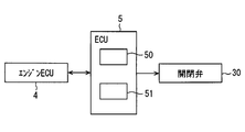
- the control device 5 includes a device such as a microcomputer that operates according to a program as a main hardware element. As illustrated in FIG. 2, the control device 5 includes an interface unit 50 (hereinafter also referred to as an I / F unit 50) to which various devices and various sensors are connected, and an arithmetic processing unit 51.
- the arithmetic processing unit 51 performs determination processing and arithmetic processing according to a predetermined program using information acquired from various sensors and various measuring devices through the I / F unit 50 and various data stored in the storage unit.
- the storage unit includes a writable storage medium, and temporarily stores information based on the signal output from each detector in the storage medium.
- the storage unit is a non-transitory tangible storage medium.
- the arithmetic processing unit 51 is a determination unit in the control device 5.
- the I / F unit 50 operates various devices based on the determination result and the calculation result by the calculation processing unit 51. Therefore, the I / F unit 50 is an input unit and a control output unit in the control device 5.
- the control device 5 may be integrated with the engine control device 4 and constitute a part of the engine control device.
- the I / F unit 50 acquires engine speed, engine load information, and the like from the engine control device as engine information signals.
- the engine load information is a torque value of the engine 20, for example.
- the arithmetic processing unit 51 performs arithmetic processing on various engine information signals from the engine control device according to a preset program.
- the control device 5 controls the on-off valve 30 and the like based on the calculation result by the calculation processing unit 51.
- the control device 5 stores in advance a shaft torque map, a cooling loss heat amount map of the engine 20, a water flow rate map of the engine 20, a reference heat release amount map of the radiator 21, an opening degree map of the on-off valve 30, and various arithmetic expressions. .
- the control device 5 controls the opening degree of the on-off valve 30 based on these maps and arithmetic expressions.
- the I / F unit 50 operates devices such as the on-off valve 30 based on the calculation result by the calculation processing unit 51.
- the I / F unit 50 is connected to a terminal device serving as a user interface, such as a control panel and a portable terminal. The user can check the current driving state output from the I / F unit 50 through the display screen of the control panel, the terminal device, or the like.
- the configuration of the thermoelectric generator 1 will be described with reference to FIGS. 3 and 4.
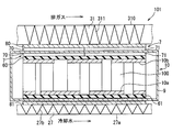
- the thermoelectric generator 1 includes a first fluid passage, a second fluid passage, a thermoelectric power generation unit 10, a low temperature side member interposed between the first fluid passage and the low temperature side portion 10a, and the second fluid passage.
- a high temperature side member interposed between the other side portion.
- the low temperature side member is a component that forms at least a part of the heat transfer path between the first fluid and the low temperature side portion 10 a, and is, for example, the heat transfer layer 81 and the insulating layer 61.
- the high temperature side member is a component that forms at least a part of the heat transfer path between the second fluid and the high temperature side portion 10b, and is, for example, the heat transfer layer 80, the thermal resistance adjustment layer 7, and the insulating layer 60.
- the low temperature side portion 10a and the high temperature side portion 10b have conductivity and constitute an electrode portion that electrically connects the thermoelectric conversion elements 100 adjacent in the flow direction of the exhaust gas.
- the circulation path 27 side and the branch path 31 side are alternately connected to each other so that the plurality of thermoelectric conversion elements 100 included in the thermoelectric power generation unit 10 are connected in series.
- An insulating layer 61 that insulates the electrode portion from the electrode portion is provided on the first fluid passage side of the low temperature side portion 10a.
- the insulating layer 61 is a thin plate-like member having thermal conductivity and electrical insulation, and is in contact with all of the plurality of electrode portions arranged along the exhaust gas flow direction.
- a heat transfer layer 81 having thermal conductivity is provided on the first fluid passage side of the insulating layer 61.
- the heat transfer layer 81 is a thin plate-like member that is sandwiched between the low-temperature passage member 27a that forms the circulation passage 27 therein and the insulating layer 61 and is in contact with both surfaces.
- the insulating layer 61 insulates the low temperature side portion 10a and the heat transfer layer 81 from each other.
- the low-temperature passage member 27a, the heat transfer layer 81, the insulating layer 61, and the thermoelectric conversion element 100 are in close contact with each other without forming an air layer and are integrally fixed.
- a fin 27b extending in the flow direction of the exhaust gas is provided as an accelerating portion that promotes heat transfer.
- the fins 27 b are members that can promote heat transfer from the low-temperature fluid flowing through the circulation passage 27 to the heat transfer layer 81.
- An insulating layer 60 that insulates the electrode part from the electrode part is provided on the second fluid passage side of the high temperature side part 10b.
- the insulating layer 60 is a thin plate-like member having thermal conductivity and electrical insulation, and is in contact with all of the plurality of electrode portions arranged along the exhaust gas flow direction.
- a heat resistance adjusting layer 7 having thermal conductivity is provided on the second fluid passage side of the insulating layer 60.
- the thermal resistance adjustment layer 7 is a member including a material such as metal or graphite.
- the thermal resistance adjusting layer 7 is preferably made of a material having a low stress relaxation rate, and can suppress a decrease in sealing performance due to a decrease in fixing force, thereby allowing close contact between each portion between the high temperature passage member 310 and the high temperature side portion 10b. Can maintain sex.
- the thermal resistance adjusting layer 7 is preferably made of a material that can also function as a thermal stress relaxation member such as graphite.
- the thermal resistance adjusting layer 7 is a member that is provided between the second fluid passage and the high temperature side portion 10b and constitutes a part of a heat path that moves between the second fluid and the high temperature side portion 10b. . Therefore, the heat of the second fluid moves to the high temperature side portion 10b through the thermal resistance adjusting layer 7.
- the thermal resistance adjusting layer 7 is configured such that the thermal resistance to heat moving along the flow direction of the second fluid is different between the upstream side portion and the downstream side portion.
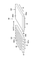
- the thermal resistance adjustment layer 7 includes an upstream adjustment layer 70 provided upstream and a downstream adjustment layer 71 provided downstream of the upstream adjustment layer 70. That is, the heat resistance adjusting layer 7 is configured to include at least two members having a difference in heat transfer rate along the flow direction of the exhaust gas.
- the thermal resistance adjustment layer 7 is configured such that one of the upstream adjustment layer 70 and the downstream adjustment layer 71 has a higher thermal resistance to heat moving along the flow direction of the second fluid than the other. .
- the thermal resistance adjustment layer 7 is configured such that the thermal resistance in the downstream adjustment layer 71 is greater than the thermal resistance in the upstream adjustment layer 70.
- a heat transfer layer 80 having heat conductivity is provided on the second fluid passage side of the heat resistance adjusting layer 7.
- the heat transfer layer 80 is a thin plate-like member that is sandwiched between the high-temperature passage member 310 that forms the branch passage 31 therein and the heat resistance adjusting layer 7 and is in contact with the surfaces of both.
- the insulating layer 60 insulates the high temperature side portion 10b from the thermal resistance adjusting layer 7 and the heat transfer layer 80.
- the high-temperature passage member 310, the heat transfer layer 80, the heat resistance adjusting layer 7, the insulating layer 60, and the thermoelectric conversion element 100 are in close contact with each other without forming an air layer, and are fixed integrally.
- fins 311 extending in the flow direction of the exhaust gas are provided as promotion portions that promote heat transfer.
- the fin 311 is a member that can promote heat transfer from the high-temperature fluid flowing through the branch passage 31 to the heat transfer layer 80.
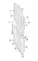
- the upstream adjustment layer 70 is configured by integrally joining a plurality of elongated graphite pieces 700 extending along the flow direction of the second fluid.
- the plurality of graphite pieces 700 are integrated in a state where the adjacent pieces are joined to each other, thereby forming the upstream adjustment layer 70.
- the graphite piece 700 has good thermal conductivity in each of the thickness direction, the longitudinal direction, and the short direction. Therefore, each of the graphite pieces 700 has good heat in both the direction D2 orthogonal to both the one side surface 70a and the other side surface 70b, the exhaust gas flow direction D1, and the direction D3 orthogonal to both the direction D2 and the direction D1. Demonstrate conductivity.
- the thermal resistance in the direction D3 is greater than the thermal resistance in each of the direction D2 and the direction D1.
- the downstream adjustment layer 71 is formed by integrally joining a plurality of elongated graphite pieces 710 extending along the direction D3.
- the plurality of graphite pieces 710 are integrated with each other adjacent to each other to form the downstream adjustment layer 71.
- the graphite piece 710 has good thermal conductivity in each of the thickness direction, the longitudinal direction, and the short direction. Therefore, each of the graphite pieces 710 has good thermal conductivity in any of the direction D2 orthogonal to both the one side surface 71a and the other side surface 71b, the flow direction D1, and the direction D3 orthogonal to both the direction D2 and the direction D1. Demonstrate.
- the thermal resistance in the flow direction D1 is larger than the thermal resistance in each of the direction D2 and the direction D3.
- the downstream adjusting layer 71 whose thermal resistance in the flow direction D1 is larger than that of the upstream adjusting layer 70 is configured by arranging a plurality of graphite pieces 710 along the flow direction D1.
- the upstream adjusting layer 70 whose thermal resistance in the flow direction D ⁇ b> 1 is smaller than the downstream adjusting layer 71 is formed by joining a plurality of graphite pieces 700 each having an elongated shape in the flow direction D ⁇ b> 1. It is configured integrally in a state.
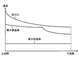
- the horizontal axis indicates the displacement in the flow direction D1.
- the vertical axis indicates the temperature of each part described above.
- the exhaust gas has the highest temperature at the upstream end, the temperature rapidly decreases from the upstream end, and gradually decreases toward the downstream end.
- the low temperature side part 10a in the thermoelectric conversion element 100 exhibits a substantially constant temperature in the flow direction.
- the temperature change rate in the exhaust gas flow direction in the high temperature side portion 10 b of the thermoelectric conversion element 100 is different between a range corresponding to the upstream adjustment layer 70 and a range corresponding to the downstream adjustment layer 71.
- the thermal resistance in the flow direction D1 is small.
- the heat absorbed on the upstream side smoothly conducts to the downstream side, so that the temperature on the downstream side is the upstream side.
- the temperature does not drop greatly with respect to the temperature. Therefore, as shown in FIG.
- thermoelectric conversion element 100 of the range corresponding to the upstream adjustment layer 70 can be raised.
- the joining surface of the graphite piece portion 710 and the graphite piece portion 710 is aligned in the flow direction D1, so that the thermal resistance in the flow direction D1 is large.
- the heat absorbed on the upstream side does not smoothly conduct to the downstream side, so that the heat tends to stagnate on the upstream side and the temperature on the downstream side is upstream.
- the temperature greatly decreases with respect to the temperature. Accordingly, as shown in FIG. 5, the high temperature side portion 10 b has a large temperature decrease degree from the upstream to the downstream, and therefore, low temperature exhaust heat can be recovered.
- thermoelectric conversion element 100 of the range corresponding to the downstream adjustment layer 71 the electric power generation amount with respect to low-temperature exhaust heat can be raised.
- the thermal resistance adjusting layer 7 is effective in terms of the amount of power generation in the thermoelectric conversion element 100 in a range corresponding to each of the upstream adjusting layer 70 and the downstream adjusting layer 71.
- the thermoelectric generator 1 includes a first fluid passage through which a first fluid flows, a second fluid passage through which a second fluid discharged from the engine 20 at a temperature higher than that of the first fluid, and a thermoelectric conversion element 100. And a thermoelectric power generation unit 10 that generates power by a temperature difference between the portion 10a and the high temperature side portion 10b.
- the thermoelectric generator 1 includes at least one of a heat transfer path between the low temperature side member forming at least a part of the heat transfer path between the first fluid and the low temperature side part 10a and the second fluid and the high temperature side part 10b. And a high temperature side member forming a part.
- the high temperature side member is configured such that the thermal resistance to heat moving along the flow direction D1 of the second fluid is greater in the downstream side portion provided downstream than the upstream side portion provided upstream. .
- thermoelectric conversion element 100 in the range corresponding to the upstream side portion According to the configuration in which the thermal resistance in the flow direction D1 of the second fluid is smaller in the upstream side portion of the high temperature side member than in the downstream side portion, heat is easily transmitted downstream in the thermoelectric conversion element 100 in the range corresponding to the upstream side portion.
- the degree of temperature decrease toward the downstream is small.
- the thermoelectric conversion element 100 in the range corresponding to the upstream side portion can recover high-temperature exhaust heat. Therefore, the thermoelectric conversion element 100 in the range corresponding to the upstream side portion has an effect of increasing the power generation amount.
- the downstream heat transmission is not smooth in the downstream side portion as compared with the upstream side portion, and thus the degree of temperature decrease is large toward the downstream side.
- thermoelectric conversion element 100 in the range corresponding to the downstream side portion has an effect of increasing the amount of power generation with respect to low temperature exhaust heat.
- efficient power generation can be realized.
- the high temperature side member is a thermal resistance adjustment layer 7 provided between the second fluid passage and the high temperature side portion 10b and formed of a material containing graphite.
- the upstream side adjusting layer 70 and the downstream side adjusting layer 71 having the larger thermal resistance in the flow direction D ⁇ b> 1 have a plurality of elongated graphite pieces 710 arranged along the flow direction D ⁇ b> 1. It is constituted by. According to this, a joining surface or a gap is formed between the adjacent graphite piece portions 710 and the graphite piece portions 710 in the adjustment layer having the higher thermal resistance. For this reason, thermal resistance is generated when heat moves between adjacent graphite pieces 710. Therefore, by arranging a plurality of graphite piece portions 710 at intervals or by laminating them together, it is possible to configure an adjustment layer having a higher thermal resistance without adopting a complicated structure.
- the plurality of graphite pieces 710 are integrally formed in a state where the adjacent pieces are joined to each other. According to this, since the bonding surface is formed between the adjacent graphite piece portions 710 and the graphite piece portions 710 in the adjustment layer having the larger thermal resistance, the heat is generated between the adjacent graphite piece portions 710. Thermal resistance is generated when moving. Therefore, by laminating a plurality of graphite piece portions 710 integrally, an adjustment layer having a stable shape and a higher thermal resistance can be configured.
- the upstream adjusting layer 70 having the smaller thermal resistance is integrally formed with a plurality of elongated graphite pieces 700 in the flow direction D1 joined together.
- the downstream side adjustment layer 71 having the larger thermal resistance and the upstream side adjustment layer 70 having the smaller thermal resistance can be manufactured in the same shape and configuration, and installed by changing the orientation.
- the upstream adjustment layer 70 and the downstream adjustment layer 71 that exhibit different functions can be provided. Therefore, it can contribute to reducing the manufacturing cost of the thermal resistance adjusting layer 7.
- the thermal resistance adjustment layer 107 will be described with reference to FIGS. 6 and 7.
- the second embodiment differs from the first embodiment only in the thermal resistance adjustment layer 107.
- the thermal resistance adjustment layer 107 is another form of the thermal resistance adjustment layer 7 of the first embodiment.
- the configuration, processing, action, and effect that are not particularly described in the second embodiment are the same as those in the first embodiment, and differences from the first embodiment will be described below.
- the thermal resistance adjusting layer 107 is configured so that the thermal resistance against heat moving along the flow direction D1 is different between the upstream side portion and the downstream side portion.
- the thermal resistance adjustment layer 107 includes an upstream adjustment layer 170 provided upstream and a downstream adjustment layer 171 provided downstream from the upstream adjustment layer 170. That is, the thermal resistance adjusting layer 107 is configured to include at least two members having a difference in heat transfer rate along the flow direction of the exhaust gas.
- the thermal resistance adjustment layer 107 is configured such that the thermal resistance in the upstream adjustment layer 170 is larger than the thermal resistance in the downstream adjustment layer 171.
- the downstream adjustment layer 171 is configured by integrally joining a plurality of elongated graphite pieces 700 extending along the flow direction D1.
- the plurality of graphite pieces 700 are integrated in a state where the adjacent pieces are joined to each other, thereby forming the downstream adjustment layer 171.
- the upstream adjustment layer 170 is configured by integrally joining a plurality of elongated graphite pieces 710 extending along the direction D3.
- the plurality of graphite pieces 710 are integrated with each other adjacent to each other to form the upstream adjustment layer 170. Since the plurality of graphite pieces 710 forming the upstream adjustment layer 170 are arranged along the flow direction D1, they form a joint surface aligned along the flow direction D1. For this reason, in the upstream adjustment layer 170, the thermal resistance in the flow direction D1 is larger than the thermal resistance in each of the direction D2 and the direction D3.
- the upstream adjustment layer 170 in which the thermal resistance in the flow direction D1 is larger than that in the downstream adjustment layer 171 is configured by arranging a plurality of graphite pieces 700 along the flow direction D1.
- the downstream adjusting layer 171 whose thermal resistance in the flow direction D1 is smaller than that of the upstream adjusting layer 170 is formed by joining a plurality of graphite pieces 700 each having an elongated shape in the flow direction D1. It is configured integrally in a state.
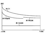
- the temperature distribution in the exhaust gas flow direction of each of the element high temperature end, the element low temperature end, and the exhaust gas in the thermoelectric generator will be described with reference to the graph of FIG.
- the horizontal axis indicates the displacement in the flow direction D1
- the vertical axis indicates the temperature of each part described above.
- the temperature change rate in the exhaust gas flow direction at the high temperature side portion 10b of the thermoelectric conversion element 100 differs between a range corresponding to the upstream adjustment layer 170 and a range corresponding to the downstream adjustment layer 171.
- the thermal resistance in the flow direction D1 is large.
- the heat absorbed on the upstream side does not smoothly conduct to the downstream side, so the heat tends to stagnate on the upstream side and the temperature on the downstream side is upstream.
- the temperature greatly decreases with respect to the temperature.
- thermoelectric conversion element 100 corresponding to the upstream side of the upstream adjustment layer 170 tends to be high in the high temperature side portion 10 b. Thereby, there exists an effect which raises the electric power generation amount in the thermoelectric conversion element 100 located upstream.
- the thermal resistance in the flow direction D1 is small.
- the heat absorbed on the upstream side is easily conducted to the downstream side smoothly, so the downstream temperature is larger than the upstream temperature. It does not decline. Therefore, as shown in FIG. 7, in the high temperature side portion 10b, since the degree of temperature decrease from the upstream to the downstream is small, a large amount of exhaust heat of the high temperature fluid can be recovered on the downstream side. Thereby, the electric power generation amount in the whole thermoelectric conversion element 100 of the range corresponding to the downstream adjustment layer 171 can be raised.
- the thermal resistance adjustment layer 107 is effective in terms of the amount of power generation in the thermoelectric conversion element 100 in the range corresponding to each of the upstream adjustment layer 170 and the downstream adjustment layer 171.
- the high temperature side member is configured such that the thermal resistance to heat moving along the second fluid flow direction D1 is greater in the upstream side than in the downstream side. ing.
- thermoelectric conversion element 100 According to the configuration in which the upstream side portion of the high temperature side member has a larger thermal resistance in the flow direction D1 than the downstream side portion, the heat is stagnant in the upstream side portion so that it does not easily flow toward the downstream side. The temperature of the thermoelectric conversion element 100 is likely to rise. For this reason, the upstream thermoelectric conversion element 100 has an effect of increasing the power generation amount. Furthermore, in the thermoelectric conversion element 100 in a range corresponding to the downstream side portion, heat is easily transmitted to the downstream side, so that the degree of temperature decrease toward the downstream side is small. For this reason, it becomes possible to enlarge the high-low temperature difference of the thermoelectric conversion element 100 over the flow direction D1.
- thermoelectric conversion element 100 the temperature difference between the high temperature side portion 10b and the low temperature side portion 10ba is large, and this temperature difference does not decrease greatly on the downstream side in the flow direction D1. Thereby, there exists an effect which raises electric power generation amount in the thermoelectric conversion element 100 of the range corresponding to a downstream side part. As described above, according to the thermoelectric generator 1, efficient power generation can be realized.
- thermoelectric generator 101 (Third embodiment) A thermoelectric generator 101 according to a third embodiment will be described with reference to FIG. Compared to the thermoelectric generator 1 described above, the thermoelectric generator 101 includes a thermoelectric generator 10, an insulating layer 60, an insulating layer 61, a thermal resistance adjusting layer 7 from the thermoelectric generator, and the like inside the case 9. Is different.
- the configuration, processing, operation, and effects that are not particularly described in the third embodiment are the same as those in the above-described embodiment, and differences from the above-described embodiment will be described below.
- the inside of the case 9 is preferably set to a vacuum state.
- the case 9 has a structure in which the thermal resistance adjusting layer 7, the insulating layer 60, the high temperature side portion 10b, the thermoelectric conversion element 100, the low temperature side portion 10a, and the insulating layer 61 are arranged in this order from the high temperature fluid passage side to the low temperature fluid passage side. Built in one. Therefore, the case 9 holds the integrated structure in a state in which adhesion is maintained so that no gap is generated between the respective parts.
- a heat transfer layer 80 is interposed between the outer surface of the case 9 in the range corresponding to the insulating layer 61 and the low-temperature passage member 27a, and the outer surface of the case 9 in the range corresponding to the thermal resistance adjusting layer 7 Between the high temperature passage member 310, the heat transfer layer 80 and the thermal resistance adjusting layer 7 are interposed.
- the case 9, the thermal resistance adjusting layer 7, the heat transfer layer 80, and the high temperature passage member 310 are integrated in a state in which adhesion is ensured so that no gap is generated between the respective parts.
- the case 9, the heat transfer layer 81, and the low-temperature passage member 27a are integrated in a state in which adhesion is ensured so that no gap is generated between the respective parts.
- thermoelectric generator 201 having an insulating layer 160 having different thermal resistance in the flow direction D1 between the upstream side portion and the downstream side portion will be described with reference to FIGS. 9 and 10.
- the configuration, processing, operation, and effects not particularly described in the fourth embodiment are the same as those in the first embodiment, and differences from the first embodiment will be described below.
- the insulating layer 160 is configured such that the thermal resistance to heat moving along the flow direction D1 is different between the upstream side portion and the downstream side portion.
- the insulating layer 160 includes an upstream layer 1601 provided upstream and a downstream layer 1602 provided downstream from the upstream layer 1601. That is, the insulating layer 160 includes at least two members having different heat transfer rates along the flow direction of the exhaust gas.
- the insulating layer 160 is configured such that the thermal resistance in the flow direction D1 in the upstream layer 1601 is greater than the thermal resistance in the flow direction D1 in the downstream layer 1602.
- the insulating layer 160 is made of the same material as the insulating layer 60.
- the high-temperature passage member 310, the heat transfer layer 80, the graphite layer 407, the insulating layer 160, and the thermoelectric conversion element 100 are in close contact with each other without forming an air layer and are integrally fixed.
- the graphite layer 407 is a thin plate-like member that is formed of a material containing graphite and is provided so as to fill the space between the heat transfer layer 80 and the insulating layer 160.
- the upstream layer 1601 is configured by arranging a plurality of elongated pieces 1600 extending along the direction D3 at intervals along the flow direction D1. Each of the pieces 1600 has thermal conductivity in both the direction D2 orthogonal to both the one side surface 1601a and the other side surface 1601b, the flow direction D1, and the direction D3 orthogonal to both the direction D2 and the direction D1.
- the thermal resistance of the upstream layer 1601 in the flow direction D1 in which the plurality of pieces 1600 is arranged is changed in the direction D3 that is the longitudinal direction of the piece 1600 and in the thickness direction. It becomes larger than a certain direction D2.
- the upstream layer 1601 whose thermal resistance in the flow direction D1 is larger than that of the downstream layer 1602 is configured by arranging a plurality of pieces 1600 along the flow direction D1.
- the downstream layer 1602 whose thermal resistance in the flow direction D1 is smaller than that of the upstream layer 1601 is a thin plate-like member having a volume equivalent to that of the upstream layer 1601.
- the downstream layer 1602 has thermal conductivity in any of the direction D2 orthogonal to both the one side surface 1602a and the other side surface 1602b, the flow direction D1, and the direction D3 orthogonal to both the direction D2 and the direction D1.
- thermoelectric generator 201 the temperature distribution in the exhaust gas flow direction of each of the element high temperature end, element low temperature end, and exhaust gas is as shown in the graph of FIG.
- the temperature change rate in the exhaust gas flow direction in the high temperature side portion 10b of the thermoelectric conversion element 100 is different between a range corresponding to the upstream layer 1601 and a range corresponding to the downstream layer 1602.
- the thermal resistance in the flow direction D1 is large.
- the heat absorbed on the upstream side does not conduct smoothly to the downstream side, so heat tends to stagnate on the upstream side and the temperature on the downstream side is on the upstream side. Decreases significantly with temperature.
- the temperature of the thermoelectric conversion element 100 corresponding to the upstream of the upstream layer 1601 tends to be high.
- the upstream layer 1601 has an effect of increasing the amount of power generation in the thermoelectric conversion element 100 located upstream.
- the thermal resistance in the flow direction D1 is small.
- the heat absorbed on the upstream side is easy to conduct smoothly to the downstream side, so the temperature on the downstream side greatly decreases with respect to the temperature on the upstream side. do not do. Therefore, in the high temperature side portion 10b, since the degree of temperature decrease from upstream to downstream is small, a large amount of exhaust heat of the high temperature fluid can be recovered on the downstream side. Thereby, the electric power generation amount in the whole thermoelectric conversion element 100 of the range corresponding to the downstream layer 1602 can be raised.
- the insulating layer 160 is effective in terms of power generation in the thermoelectric conversion elements 100 in the ranges corresponding to the upstream layer 1601 and the downstream layer 1602, respectively.
- the upstream layer 1601 having the higher thermal resistance in the insulating layer 160 may have a configuration in which pieces 1600 adjacent in the flow direction of the second fluid are integrally joined without a gap. Also in this case, the thermal resistance of the insulating layer 160 in the arrangement direction of the plurality of pieces 1600 is larger than the longitudinal direction and the thickness direction of the pieces 1600 as in the above-described embodiment.
- the insulating layer 160 which is one form of the high temperature side member, has a thermal resistance to heat that moves along the flow direction D1 of the second fluid on the upstream side of the downstream side. It is configured to be larger.
- the upstream layer 1601 stagnates in such a way that heat hardly flows downstream, and therefore corresponds to the upstream of the upstream layer 1601.
- the temperature of the thermoelectric conversion element 100 is likely to rise.
- the thermoelectric conversion element 100 in the range corresponding to the downstream side layer 1602 since heat is easily transmitted to the downstream, the degree of temperature decrease toward the downstream is small. Thereby, the high-low temperature difference of the thermoelectric conversion element 100 can be enlarged over the flow direction D1. Therefore, the thermoelectric conversion element 100 in the range corresponding to the downstream layer 1602 has an effect of increasing the power generation amount.
- efficient power generation can be realized.
- the insulating layer 160 has a larger thermal resistance in the flow direction D1, and is configured by arranging a plurality of elongated pieces 1600 along the flow direction D1. ing. According to this, a bonding surface or a gap is formed between the adjacent piece 1600 and the piece 1600 in the layer having the higher thermal resistance. For this reason, thermal resistance is generated when heat moves between adjacent pieces 1600. Therefore, by arranging a plurality of pieces 1600 at intervals or by stacking them together, a thermal resistance adjusting layer having a higher thermal resistance can be configured without adopting a complicated structure.
- the thermal resistance adjustment layer 207 will be described with reference to FIG.
- the fifth embodiment differs from the first embodiment only in the thermal resistance adjustment layer 207.
- the thermal resistance adjustment layer 207 is another form of the thermal resistance adjustment layer 7 of the first embodiment.
- the configuration, processing, operation, and effects not particularly described in the fifth embodiment are the same as those in the first embodiment, and differences from the first embodiment will be described below.
- the thermal resistance adjusting layer 207 is configured such that the thermal resistance against heat moving along the flow direction D1 is different between the upstream side portion and the downstream side portion.
- the thermal resistance adjustment layer 207 includes an upstream adjustment layer 270 provided upstream and a downstream adjustment layer 271 provided downstream from the upstream adjustment layer 270.
- the thermal resistance adjustment layer 207 is configured such that the thermal resistance in the downstream adjustment layer 271 is larger than the thermal resistance in the upstream adjustment layer 270.
- the downstream adjustment layer 271 has the same configuration as the downstream adjustment layer 71 of the first embodiment. Therefore, in the downstream adjustment layer 271, the thermal resistance related to the flow direction D1 is larger than the thermal resistance related to each of the direction D2 and the direction D3 orthogonal to both the one side surface 271a and the other side surface 271b.
- the upstream adjustment layer 270 is a thin plate-like member and exhibits good thermal conductivity in any of the flow direction D1, the direction D2 perpendicular to both the one side surface 270a and the other side surface 270b, and the direction D3. Therefore, the upstream adjustment layer 270 has no significant difference in thermal resistance in that direction.
- the thermal resistance adjustment layer 307 will be described with reference to FIG.
- the sixth embodiment differs from the second embodiment only in the thermal resistance adjustment layer 307.
- the thermal resistance adjustment layer 307 is another form with respect to the thermal resistance adjustment layer 107 of the second embodiment.
- the configuration, processing, action, and effects that are not particularly described in the sixth embodiment are the same as those in the second embodiment, and differences from the second embodiment will be described below.
- the thermal resistance adjusting layer 307 is configured such that the thermal resistance to heat moving along the flow direction D1 is different between the upstream side portion and the downstream side portion.
- the thermal resistance adjustment layer 307 includes an upstream adjustment layer 170 provided upstream and a downstream adjustment layer 370 provided downstream of the upstream adjustment layer 170.
- the thermal resistance adjustment layer 307 is configured such that the thermal resistance in the upstream adjustment layer 170 is larger than the thermal resistance in the downstream adjustment layer 370.
- the thermal resistance related to the flow direction D1 in the upstream adjustment layer 170 is larger than the thermal resistance related to each of the direction D2 and the direction D3 perpendicular to both the one side surface 170a and the other side surface 170b.
- the downstream adjustment layer 370 is a thin plate-like member, and exhibits good thermal conductivity in any of the flow direction D1, the direction D2 perpendicular to both the one side surface 370a and the other side surface 370b, and the direction D3. Accordingly, the downstream adjustment layer 370 has no significant difference in thermal resistance in that direction.
- the plurality of graphite pieces 700 constituting the upstream adjustment layer and the downstream adjustment layer may be formed such that a gap is formed between the adjacent graphite pieces 700 and 700. Good. Also in this case, the thermal resistance of the thermal resistance adjusting layer in the arrangement direction of the plurality of graphite pieces 700 is larger than the longitudinal direction and the thickness direction of the graphite pieces 700 as in the above-described embodiment.
- the plurality of graphite piece portions 710 constituting the upstream adjustment layer and the downstream adjustment layer have gaps between the graphite piece portions 710 and the graphite piece portions 710 adjacent in the flow direction of the second fluid. May be formed. Also in this case, the thermal resistance of the thermal resistance adjusting layer in the arrangement direction of the plurality of graphite pieces 710 is larger than the longitudinal direction and the thickness direction of the graphite pieces 710, as in the above-described embodiment.
- a plurality of heat resistance adjusting layers may be provided between the high temperature side portion 10b and the high temperature passage member 310.
- the insulating layer 160 of the fourth embodiment has a configuration in which the upstream layer 1601 has a higher thermal resistance in the flow direction D1 than the downstream layer 1602, but the downstream layer 1602 has a heat in the flow direction D1 higher than the upstream layer 1601. It is good also as a structure with large resistance. In this case, the same operation and effect as the thermal resistance adjustment layer 7 of the first embodiment are exhibited.
- the first fluid and the second fluid may form counterflows that flow in opposite directions.
Abstract
A thermoelectric power generation device is provided with: a first fluid passageway (27) through which a first fluid flows; a second fluid passageway (31) through which a second fluid having a higher temperature than the first fluid and being discharged from an engine (20) flows; a thermoelectric power generation unit (10) which includes a thermoelectric conversion element (100) and which generates electric power using a temperature difference between one side portion (10a) and another side portion (10b); a lower temperature side member (61, 81) which is interposed between the first fluid passageway and the one side portion and constitutes at least a part of a thermal transfer path between the first fluid and the one side portion; and a higher temperature side member (7; 107; 160; 207; 307) which is interposed between the second fluid passageway and the other side portion and constitutes at least a part of a thermal transfer path between the second fluid and the other side portion. The higher temperature side member is configured such that the thermal resistance to heat moving in the direction of the flow of the second fluid is greater in one than the other of an upstream side portion (70; 170; 1601; 170; 270) provided upstream and a downstream side portion (71; 171; 1602; 271; 370) provided downstream of the upstream side portion.
Description
本出願は、2016年7月4日に出願された日本特許出願番号2016-132840号に基づくもので、ここにその記載内容を援用する。
This application is based on Japanese Patent Application No. 2016-132840 filed on July 4, 2016, the contents of which are incorporated herein by reference.
本開示は、ゼーベック効果により熱エネルギを電力エネルギに変換する熱電発電装置に関する。
This disclosure relates to a thermoelectric generator that converts thermal energy into electric energy by the Seebeck effect.
特許文献1の熱電発電装置は、熱電変換素子からなるモジュールの高温側面と、高温媒体通路を備えた高温側部材との間に介在する熱応力緩和材を備えている。熱応力緩和材は電導性を有するグラファイトによって形成されている。熱応力緩和材は、一平面において多数並列した短冊状のグラファイト材を一体に形成したシート状の部材である。
The thermoelectric power generation device of Patent Document 1 includes a thermal stress relaxation material interposed between a high temperature side surface of a module composed of a thermoelectric conversion element and a high temperature side member having a high temperature medium passage. The thermal stress relaxation material is made of conductive graphite. The thermal stress relieving material is a sheet-like member formed integrally with strip-like graphite materials arranged in parallel on one plane.
特許文献1によると、高温媒体と熱電変換素子の高温側面との間に介在する熱応力緩和材について、その表裏面に直交する方向に層間が存在しないため、この直交方向の熱伝導が良好になり、高温媒体と熱電変換素子の高温側面との熱抵抗を小さくできる。
According to Patent Document 1, the thermal stress relaxation material interposed between the high-temperature medium and the high-temperature side surface of the thermoelectric conversion element has no interlayer in the direction orthogonal to the front and back surfaces, so that the heat conduction in the orthogonal direction is good. Thus, the thermal resistance between the high temperature medium and the high temperature side surface of the thermoelectric conversion element can be reduced.
しかしながら、特許文献1の熱応力緩和材には、高温媒体の流れ方向に関する熱の伝わり方が考慮されていない。特許文献1の熱応力緩和材には、熱電変換素子の高温側面に熱を与える高温媒体の流れ方向全体について効率的な発電を実施するために改良の余地が十分ある。
However, the thermal stress relaxation material of Patent Document 1 does not consider how heat is transmitted in the flow direction of the high-temperature medium. The thermal stress relaxation material of Patent Document 1 has sufficient room for improvement in order to efficiently generate power in the entire flow direction of the high-temperature medium that applies heat to the high-temperature side surface of the thermoelectric conversion element.
このような課題に鑑み、本開示の目的は、効率的な発電を図る熱電発電装置を提供することである。
In view of such a problem, an object of the present disclosure is to provide a thermoelectric power generation apparatus that performs efficient power generation.
上記目的を達成するために、本開示のひとつの態様の熱電発電装置は、第1流体が流れる第1流体通路と、第1流体よりも高温であり、エンジンから排出される第2流体が流れる第2流体通路と、熱電変換素子を有し、一方側部と他方側部との温度差によって発電する熱電発電部と、第1流体通路と一方側部との間に介在して、第1流体と一方側部との間の熱移動経路の少なくとも一部をなす低温側部材と、第2流体通路と他方側部との間に介在して、第2流体と他方側部との間の熱移動経路の少なくとも一部をなす高温側部材と、を備え、高温側部材は、第2流体の流れ方向に沿って移動する熱に対する熱抵抗が、上流に設けられる上流側部と上流側部よりも下流に設けられる下流側部とにおいて一方が他方よりも大きくなるように構成されている。
In order to achieve the above object, a thermoelectric power generation device according to one aspect of the present disclosure includes a first fluid passage through which a first fluid flows, and a second fluid that is hotter than the first fluid and discharged from an engine. A first fluid passage, a thermoelectric generator having a thermoelectric conversion element and generating electricity by a temperature difference between the one side and the other side, and the first fluid passage and the one side, A low temperature side member forming at least a part of a heat transfer path between the fluid and the one side part, and interposed between the second fluid passage and the other side part, and between the second fluid and the other side part. A high-temperature side member that forms at least a part of the heat transfer path, and the high-temperature side member has an upstream side portion and an upstream side portion that are provided upstream with thermal resistance to heat that moves along the flow direction of the second fluid. Configured so that one is larger than the other at the downstream side provided downstream It has been.
この熱電発電装置によれば、高温側部材の上流側部が下流側部よりも第2流体の流れ方向の熱抵抗が小さくなるように構成した場合には、上流側部に対応する範囲の熱電変換素子では、下流に向けての温度低下度合いが小さいので高温の排熱が回収可能になる。これによって、上流側部に対応する範囲の熱電変換素子において発電量の向上が図れる。さらに下流側部に対応する範囲の熱電変換素子では、下流に向けて温度低下度合いが大きいので低温の排熱が回収可能になり、下流側部に対応する範囲の熱電変換素子において低温排熱に対する発電量の向上が図れる。
According to this thermoelectric generator, when the upstream side portion of the high temperature side member is configured to have a smaller thermal resistance in the flow direction of the second fluid than the downstream side portion, a thermoelectric power in a range corresponding to the upstream side portion is obtained. In the conversion element, since the degree of temperature decrease toward the downstream is small, high-temperature exhaust heat can be recovered. As a result, the amount of power generation can be improved in the thermoelectric conversion element in the range corresponding to the upstream side portion. Further, in the thermoelectric conversion element in the range corresponding to the downstream side portion, the temperature decrease degree is large toward the downstream, so that the low-temperature exhaust heat can be recovered, and in the thermoelectric conversion element in the range corresponding to the downstream side portion, The amount of power generation can be improved.
また、高温側部材の上流側部が下流側部よりも第2流体の流れ方向の熱抵抗が大きくなるように構成した場合には、上流側部において熱が下流に向けて流れにくいため、上流側部の上流に対応する熱電変換素子の温度が高くなりやすい。これにより、上流の熱電変換素子において発電量の向上が図れる。さらに下流側部に対応する範囲の熱電変換素子では、下流に向けての温度低下度合いが小さいので、流れ方向にわたって素子の高低温度差を大きくすることが可能になる。これによって、下流側部に対応する範囲の熱電変換素子において発電量の向上が図れる。以上により、この熱電発電装置によれば、効率的な発電を提供できる。
In addition, when the upstream side portion of the high temperature side member is configured to have a greater thermal resistance in the flow direction of the second fluid than the downstream side portion, heat does not easily flow downstream in the upstream side portion. The temperature of the thermoelectric conversion element corresponding to the upstream of the side portion tends to be high. Thereby, the power generation amount can be improved in the upstream thermoelectric conversion element. Further, in the thermoelectric conversion element in the range corresponding to the downstream side portion, the temperature decrease degree toward the downstream is small, so that the temperature difference between the elements in the flow direction can be increased. As a result, the amount of power generation can be improved in the thermoelectric conversion element in the range corresponding to the downstream side portion. As described above, according to this thermoelectric power generator, efficient power generation can be provided.
本開示についての上記目的およびその他の目的、特徴や利点は、添付の図面を参照しながら下記の詳細な記述により、より明確になる。その図面は、
第1実施形態の熱電発電装置と冷却水および排ガスとの関係を示した概要図である。
第1実施形態の熱電発電装置に関する制御構成図である。
第1実施形態の熱電発電装置の構成を示した図である。
第1実施形態の熱抵抗調整層を示した斜視図である。
第1実施形態の熱電発電装置において、素子高温端、素子低温端、および排ガスのそれぞれについて排ガス流れ方向の温度分布を示したグラフである。
第2実施形態の熱抵抗調整層を示した斜視図である。
第2実施形態の熱電発電装置において、素子高温端、素子低温端、および排ガスのそれぞれについて排ガス流れ方向の温度分布を示したグラフである。
第3実施形態の熱電発電装置の構成を示した図である。
第4実施形態の熱電発電装置の構成を示した図である。
第4実施形態の熱抵抗調整層を示した斜視図である。
第5実施形態の熱抵抗調整層を示した斜視図である。
第6実施形態の熱抵抗調整層を示した斜視図である。
The above and other objects, features and advantages of the present disclosure will become more apparent from the following detailed description with reference to the accompanying drawings. The drawing
It is the schematic which showed the relationship between the thermoelectric generator of 1st Embodiment, a cooling water, and waste gas. It is a control block diagram regarding the thermoelectric power generator of 1st Embodiment. It is the figure which showed the structure of the thermoelectric generator of 1st Embodiment. It is the perspective view which showed the thermal resistance adjustment layer of 1st Embodiment. In the thermoelectric generator of a 1st embodiment, it is a graph which showed temperature distribution of an exhaust gas flow direction about each of element high temperature end, element low temperature end, and exhaust gas. It is the perspective view which showed the thermal resistance adjustment layer of 2nd Embodiment. In the thermoelectric generator of a 2nd embodiment, it is a graph which showed temperature distribution of an exhaust gas flow direction about each of a device high temperature end, a device low temperature end, and exhaust gas. It is the figure which showed the structure of the thermoelectric power generating apparatus of 3rd Embodiment. It is the figure which showed the structure of the thermoelectric power generating apparatus of 4th Embodiment. It is the perspective view which showed the thermal resistance adjustment layer of 4th Embodiment. It is the perspective view which showed the thermal resistance adjustment layer of 5th Embodiment. It is the perspective view which showed the thermal resistance adjustment layer of 6th Embodiment.
以下に、図面を参照しながら本開示を実施するための複数の形態を説明する。各形態において先行する形態で説明した事項に対応する部分には同一の参照符号を付して重複する説明を省略する場合がある。各形態において構成の一部のみを説明している場合は、構成の他の部分については先行して説明した他の形態を適用することができる。各実施形態で具体的に組み合わせが可能であることを明示している部分同士の組み合わせばかりではなく、特に組み合わせに支障が生じなければ、明示していなくても実施形態同士を部分的に組み合せることも可能である。
Hereinafter, a plurality of modes for carrying out the present disclosure will be described with reference to the drawings. In each embodiment, parts corresponding to the matters described in the preceding embodiment may be denoted by the same reference numerals, and redundant description may be omitted. When only a part of the configuration is described in each mode, the other modes described above can be applied to the other parts of the configuration. Not only combinations of parts that clearly indicate that the combination is possible in each embodiment, but also a combination of the embodiments even if they are not clearly specified unless there is a problem with the combination. It is also possible.
(第1実施形態)
第1実施形態の熱電発電装置1について、図1~図5を参照して説明する。熱電発電装置1は、エンジン20から排出される第2流体としての排ガスと排ガスよりも低温である第1流体との温度差を利用して、ゼーベック効果により熱エネルギを電力エネルギに変換する装置である。熱電発電装置1は、熱電変換素子を有する熱電発電部10において一方側部である低温側部10aと他方側部である高温側部10bとに温度差が与えられると、電位差が生じて電子が流れる現象を利用して発電する。第1流体には排ガスと温度差を与えることが可能な任意の流体を採用することができる。この実施形態では、任意に選択可能な低温流体の一例として、自動車のエンジン20の冷却水を用いる場合について説明する。 (First embodiment)
Athermoelectric generator 1 according to a first embodiment will be described with reference to FIGS. The thermoelectric generator 1 is a device that converts thermal energy into electric energy by the Seebeck effect using a temperature difference between the exhaust gas as the second fluid discharged from the engine 20 and the first fluid that is lower in temperature than the exhaust gas. is there. When a temperature difference is given between the low-temperature side part 10a that is one side and the high-temperature side part 10b that is the other side in the thermoelectric power generation part 10 having a thermoelectric conversion element, the thermoelectric power generation apparatus 1 generates a potential difference and electrons are generated. Electricity is generated using the flowing phenomenon. Any fluid capable of giving a temperature difference from the exhaust gas can be adopted as the first fluid. In this embodiment, a case where cooling water of an automobile engine 20 is used as an example of an arbitrarily selectable low-temperature fluid will be described.
第1実施形態の熱電発電装置1について、図1~図5を参照して説明する。熱電発電装置1は、エンジン20から排出される第2流体としての排ガスと排ガスよりも低温である第1流体との温度差を利用して、ゼーベック効果により熱エネルギを電力エネルギに変換する装置である。熱電発電装置1は、熱電変換素子を有する熱電発電部10において一方側部である低温側部10aと他方側部である高温側部10bとに温度差が与えられると、電位差が生じて電子が流れる現象を利用して発電する。第1流体には排ガスと温度差を与えることが可能な任意の流体を採用することができる。この実施形態では、任意に選択可能な低温流体の一例として、自動車のエンジン20の冷却水を用いる場合について説明する。 (First embodiment)
A
内燃機関であるエンジン20には、燃焼用の空気を吸入する吸気管と、燃焼後の排ガスを排出する排気管3が接続されている。吸気管内には、車両に設けられたアクセルペダルの踏み込み量に応じて開度が可変されるスロットルバルブが設けられている。エンジン20は、エンジン制御装置によって最適な作動に制御される。エンジン制御装置には、エンジン回転数信号、スロットルバルブ開度信号、および車速信号等が入力される。エンジン制御装置は、エンジン回転数信号およびスロットルバルブ開度信号に対する燃料噴射量を対応付けた制御マップを予め記憶している。エンジン制御装置は、制御マップに基づいて吸気管側に所定のタイミングで必要とされる燃料噴射量を制御する。エンジン制御装置は、熱電発電装置1の制御装置5と互いの信号の授受が通信可能となるように接続されている。
An engine 20 which is an internal combustion engine is connected to an intake pipe for sucking combustion air and an exhaust pipe 3 for discharging exhaust gas after combustion. A throttle valve whose opening is variable according to the amount of depression of an accelerator pedal provided in the vehicle is provided in the intake pipe. The engine 20 is controlled for optimal operation by an engine control device. An engine speed signal, a throttle valve opening signal, a vehicle speed signal, and the like are input to the engine control device. The engine control device stores in advance a control map in which the fuel injection amount is associated with the engine speed signal and the throttle valve opening signal. The engine control device controls the fuel injection amount required at a predetermined timing on the intake pipe side based on the control map. The engine control device is connected to the control device 5 of the thermoelectric generator 1 so as to be able to communicate with each other for transmission and reception of signals.
エンジン20には冷却水回路2が接続されている。冷却水回路2は、エンジン20を冷却するためエンジン20内の冷却水が循環する回路である。冷却水は、ウォータポンプ24によって出口部20bからラジエータ21を通過して入口部20aに流通して循環する。ウォータポンプ24は、例えば、エンジン20の駆動力を受けて作動するエンジン駆動式のポンプである。冷却水回路2を循環する冷却水は、ラジエータ21の放熱によって冷却されるので、エンジン20の作動温度を適切に制御することができる。
The cooling water circuit 2 is connected to the engine 20. The cooling water circuit 2 is a circuit through which cooling water in the engine 20 circulates to cool the engine 20. Cooling water passes through the radiator 21 from the outlet 20b through the water pump 24 and circulates through the inlet 20a. The water pump 24 is, for example, an engine-driven pump that operates by receiving the driving force of the engine 20. Since the cooling water circulating through the cooling water circuit 2 is cooled by the heat radiation of the radiator 21, the operating temperature of the engine 20 can be controlled appropriately.
冷却水回路2には、ラジエータ21をバイパスするバイパス通路26と、ラジエータ21側あるいはバイパス通路26側への冷却水流量を調節するサーモスタット22とが設けられている。冷却水温度が第1所定温度以下においては、サーモスタット22によってラジエータ21側が閉じられ、冷却水がバイパス通路26側を流通することで冷却水の過冷却を防止できる。これは、例えばエンジン20の始動直後のように冷却水が充分に昇温していない場合に対応し、エンジン20の暖機を促進することができる。さらにサーモスタット22は、エンジン20の暖機が終了して冷却水温度が第1所定温度を超えると、ラジエータ21側を開き始め、第2所定温度以上でバイパス通路26側を閉じ、ラジエータ21側を全開にする。冷却水回路2には、ラジエータ21に対して並列となるようにヒータコア23と、冷却水回路2の一部を成すヒータ温水回路25と、が設けられている。ヒータコア23は、冷却水を熱源として空調用空気を加熱する暖房装置用の熱交換器である。
The cooling water circuit 2 is provided with a bypass passage 26 that bypasses the radiator 21 and a thermostat 22 that adjusts the flow rate of the cooling water to the radiator 21 side or the bypass passage 26 side. When the cooling water temperature is equal to or lower than the first predetermined temperature, the radiator 21 side is closed by the thermostat 22 and the cooling water flows through the bypass passage 26 side, thereby preventing the cooling water from being overcooled. This corresponds to a case where the cooling water is not sufficiently heated, for example, immediately after the engine 20 is started, and warm-up of the engine 20 can be promoted. Further, when the warm-up of the engine 20 is finished and the coolant temperature exceeds the first predetermined temperature, the thermostat 22 starts to open the radiator 21 side, closes the bypass passage 26 side at the second predetermined temperature or higher, and closes the radiator 21 side. Fully open. The cooling water circuit 2 is provided with a heater core 23 and a heater hot water circuit 25 forming a part of the cooling water circuit 2 so as to be in parallel with the radiator 21. The heater core 23 is a heat exchanger for a heating device that heats air for air conditioning using cooling water as a heat source.
熱電発電装置1は、熱電発電部10と、熱電発電部10の作動を制御する制御装置5と、を備えている。熱電発電部10は、ゼーベック効果を利用して発電を行う熱電変換素子100に対して、第2流体通路である分岐通路31と、第1流体通路である循環通路27と、が配設されて構成されている。分岐通路31は、エンジン20の排気管3から分岐して再び排気管3に合流するように形成された通路を構成し、排ガスの一部が分流するように構成されている。分岐通路31は、熱電変換素子100、あるいは熱電発電部10の他方側面である高温側部10bに接触し、排ガスが熱電変換素子100の高温側熱源となる。分岐通路31の熱電変換素子100に対する排ガスの上流側には、分岐通路31を開閉する開閉弁30が設けられている。
The thermoelectric generator 1 includes a thermoelectric generator 10 and a controller 5 that controls the operation of the thermoelectric generator 10. The thermoelectric power generation unit 10 is provided with a branch passage 31 that is a second fluid passage and a circulation passage 27 that is a first fluid passage with respect to the thermoelectric conversion element 100 that generates power using the Seebeck effect. It is configured. The branch passage 31 constitutes a passage formed so as to branch from the exhaust pipe 3 of the engine 20 and merge with the exhaust pipe 3 again, and is configured such that a part of the exhaust gas is diverted. The branch passage 31 comes into contact with the thermoelectric conversion element 100 or the high temperature side portion 10 b that is the other side surface of the thermoelectric power generation unit 10, and the exhaust gas becomes a high temperature side heat source of the thermoelectric conversion element 100. An on-off valve 30 for opening and closing the branch passage 31 is provided on the upstream side of the exhaust gas with respect to the thermoelectric conversion element 100 in the branch passage 31.
循環通路27は、バイパス通路26よりもエンジン20側となる通路であり、ラジエータ21の下流側で、サーモスタット22と入口部20aとを繋ぐ通路である。循環通路27は、熱電変換素子100、あるいは熱電発電部10の一方側面である低温側部10aに接触している。バイパス通路26からサーモスタット22を流れる冷却水、あるいは、ラジエータ21を通過しサーモスタット22を流れる冷却水は、熱電変換素子100側に供給され、この冷却水が熱電変換素子100の低温側熱源となる。
The circulation passage 27 is a passage closer to the engine 20 than the bypass passage 26, and is a passage connecting the thermostat 22 and the inlet portion 20 a on the downstream side of the radiator 21. The circulation passage 27 is in contact with the thermoelectric conversion element 100 or the low temperature side portion 10 a that is one side surface of the thermoelectric power generation unit 10. The cooling water flowing through the thermostat 22 from the bypass passage 26 or the cooling water passing through the radiator 21 and flowing through the thermostat 22 is supplied to the thermoelectric conversion element 100 side, and this cooling water becomes a low temperature side heat source of the thermoelectric conversion element 100.
制御装置5は、プログラムに従って動作するマイコンのようなデバイスを主なハードウェア要素として備える。制御装置5は、図2に図示するように、各種装置と各種センサとが接続されるインターフェース部50(以下、I/F部50ともいう)と演算処理部51とを備える。演算処理部51は、I/F部50を通して各種センサ、各種測定装置から取得した情報と、記憶部に格納した各種データとを用いて所定のプログラムにしたがった判定処理や演算処理を行う。
The control device 5 includes a device such as a microcomputer that operates according to a program as a main hardware element. As illustrated in FIG. 2, the control device 5 includes an interface unit 50 (hereinafter also referred to as an I / F unit 50) to which various devices and various sensors are connected, and an arithmetic processing unit 51. The arithmetic processing unit 51 performs determination processing and arithmetic processing according to a predetermined program using information acquired from various sensors and various measuring devices through the I / F unit 50 and various data stored in the storage unit.
記憶部は、書き込み可能な記憶媒体を備えており、その記憶媒体に、各検出器から出力された信号に基づく情報を一時的に記憶する。記憶部は、非遷移的実体的記録媒体(non-transitory tangible storage media)である。演算処理部51は、制御装置5における判定部である。I/F部50は、演算処理部51による判定結果、演算結果に基づいて各種装置を操作する。したがって、I/F部50は制御装置5における入力部および制御出力部である。また、制御装置5は、エンジン制御装置4と一体化され、エンジン制御装置の一部を構成するものでもよい。
The storage unit includes a writable storage medium, and temporarily stores information based on the signal output from each detector in the storage medium. The storage unit is a non-transitory tangible storage medium. The arithmetic processing unit 51 is a determination unit in the control device 5. The I / F unit 50 operates various devices based on the determination result and the calculation result by the calculation processing unit 51. Therefore, the I / F unit 50 is an input unit and a control output unit in the control device 5. The control device 5 may be integrated with the engine control device 4 and constitute a part of the engine control device.
I/F部50は、エンジン情報信号としてエンジン回転数、エンジン負荷情報等をエンジン制御装置から取得する。エンジン負荷情報とは、例えばエンジン20のトルク値である。演算処理部51は、予め設定されたプログラムにしたがって、エンジン制御装置からの各種のエンジン情報信号等に対する演算処理を行う。制御装置5は演算処理部51による演算結果に基づいて開閉弁30等の制御を行う。制御装置5は、軸トルクマップ、エンジン20の冷却損失熱量マップ、エンジン20の通水流量マップ、ラジエータ21の基準放熱量マップ、開閉弁30の開度マップや各種演算式を予め記憶している。制御装置5は、これらのマップや演算式に基づいて開閉弁30の開度を制御する。
The I / F unit 50 acquires engine speed, engine load information, and the like from the engine control device as engine information signals. The engine load information is a torque value of the engine 20, for example. The arithmetic processing unit 51 performs arithmetic processing on various engine information signals from the engine control device according to a preset program. The control device 5 controls the on-off valve 30 and the like based on the calculation result by the calculation processing unit 51. The control device 5 stores in advance a shaft torque map, a cooling loss heat amount map of the engine 20, a water flow rate map of the engine 20, a reference heat release amount map of the radiator 21, an opening degree map of the on-off valve 30, and various arithmetic expressions. . The control device 5 controls the opening degree of the on-off valve 30 based on these maps and arithmetic expressions.
I/F部50は、演算処理部51による演算結果に基づいて開閉弁30等の機器を操作する。I/F部50には、ユーザインターフェイスとなる端末装置、例えば、コントロールパネル、携帯用端末機等が接続される。使用者は、コントロールパネルの表示部、端末装置等の表示画面を通じて、I/F部50から出力された現在の運転状態を確認することができる。
The I / F unit 50 operates devices such as the on-off valve 30 based on the calculation result by the calculation processing unit 51. The I / F unit 50 is connected to a terminal device serving as a user interface, such as a control panel and a portable terminal. The user can check the current driving state output from the I / F unit 50 through the display screen of the control panel, the terminal device, or the like.
熱電発電装置1の構成について図3および図4を参照して説明する。熱電発電装置1は、第1流体通路と、第2流体通路と、熱電発電部10と、第1流体通路と低温側部10aとの間に介在する低温側部材と、前記第2流体通路と前記他方側部との間に介在する高温側部材と、を備える。低温側部材は、第1流体と低温側部10aとの間の熱移動経路の少なくとも一部をなす構成要素であり、例えば伝熱層81、絶縁層61である。高温側部材は、第2流体と高温側部10bとの間の熱移動経路の少なくとも一部をなす構成要素であり、例えば伝熱層80、熱抵抗調整層7、絶縁層60である。
The configuration of the thermoelectric generator 1 will be described with reference to FIGS. 3 and 4. The thermoelectric generator 1 includes a first fluid passage, a second fluid passage, a thermoelectric power generation unit 10, a low temperature side member interposed between the first fluid passage and the low temperature side portion 10a, and the second fluid passage. A high temperature side member interposed between the other side portion. The low temperature side member is a component that forms at least a part of the heat transfer path between the first fluid and the low temperature side portion 10 a, and is, for example, the heat transfer layer 81 and the insulating layer 61. The high temperature side member is a component that forms at least a part of the heat transfer path between the second fluid and the high temperature side portion 10b, and is, for example, the heat transfer layer 80, the thermal resistance adjustment layer 7, and the insulating layer 60.
低温側部10a、高温側部10bは、導電性を有し、排ガスの流れ方向に隣接する熱電変換素子100を電気的に接続する電極部を構成する。熱電発電部10において電極部は、熱電発電部10に含まれる複数個の熱電変換素子100が直列に接続されるように、循環通路27側と分岐通路31側とが交互に接続されている。
The low temperature side portion 10a and the high temperature side portion 10b have conductivity and constitute an electrode portion that electrically connects the thermoelectric conversion elements 100 adjacent in the flow direction of the exhaust gas. In the thermoelectric power generation unit 10, the circulation path 27 side and the branch path 31 side are alternately connected to each other so that the plurality of thermoelectric conversion elements 100 included in the thermoelectric power generation unit 10 are connected in series.
低温側部10aの第1流体通路側には、電極部と電極部とを絶縁する絶縁層61が設けられている。絶縁層61は、熱伝導性および電気絶縁性を有する薄板状の部材であり、排ガスの流れ方向に沿って並ぶ複数個の電極部のすべてに接触している。絶縁層61の第1流体通路側には、熱伝導性を有する伝熱層81が設けられている。伝熱層81は、内部に循環通路27を形成する低温通路部材27aと絶縁層61とに挟持されて両者の表面に接触している薄板状の部材である。絶縁層61は、低温側部10aと伝熱層81とを絶縁している。低温通路部材27a、伝熱層81、絶縁層61および熱電変換素子100は、各部間に空気層を形成することなく密着し、一体に固定されている。低温通路部材27aの内部には、伝熱を促進する促進部として、排ガスの流れ方向に延びるフィン27bが設けられている。フィン27bは、循環通路27を流通する低温流体から伝熱層81への伝熱を促進可能な部材である。
An insulating layer 61 that insulates the electrode portion from the electrode portion is provided on the first fluid passage side of the low temperature side portion 10a. The insulating layer 61 is a thin plate-like member having thermal conductivity and electrical insulation, and is in contact with all of the plurality of electrode portions arranged along the exhaust gas flow direction. A heat transfer layer 81 having thermal conductivity is provided on the first fluid passage side of the insulating layer 61. The heat transfer layer 81 is a thin plate-like member that is sandwiched between the low-temperature passage member 27a that forms the circulation passage 27 therein and the insulating layer 61 and is in contact with both surfaces. The insulating layer 61 insulates the low temperature side portion 10a and the heat transfer layer 81 from each other. The low-temperature passage member 27a, the heat transfer layer 81, the insulating layer 61, and the thermoelectric conversion element 100 are in close contact with each other without forming an air layer and are integrally fixed. Inside the low temperature passage member 27a, a fin 27b extending in the flow direction of the exhaust gas is provided as an accelerating portion that promotes heat transfer. The fins 27 b are members that can promote heat transfer from the low-temperature fluid flowing through the circulation passage 27 to the heat transfer layer 81.
高温側部10bの第2流体通路側には、電極部と電極部とを絶縁する絶縁層60が設けられている。絶縁層60は、熱伝導性および電気絶縁性を有する薄板状の部材であり、排ガスの流れ方向に沿って並ぶ複数個の電極部のすべてに接触している。絶縁層60の第2流体通路側には、熱伝導性を有する熱抵抗調整層7が設けられている。熱抵抗調整層7は、例えば、金属、グラファイト等の材質を含んだ部材である。熱抵抗調整層7は、応力緩和率が小さい材質で構成することが好ましく、固定力低下によるシール性の低下を抑制できることで、高温通路部材310と高温側部10bとの間の各部間の密着性を維持できる。また、熱抵抗調整層7には、例えば、グラファイト等の熱応力緩和部材としても機能できる材質を用いることが好ましい。熱抵抗調整層7は、第2流体通路と高温側部10bとの間に設けられて、第2流体と高温側部10bとの間で移動する熱の経路の一部を構成する部材である。したがって、第2流体の熱は、熱抵抗調整層7を介して高温側部10bへ移動する。
An insulating layer 60 that insulates the electrode part from the electrode part is provided on the second fluid passage side of the high temperature side part 10b. The insulating layer 60 is a thin plate-like member having thermal conductivity and electrical insulation, and is in contact with all of the plurality of electrode portions arranged along the exhaust gas flow direction. A heat resistance adjusting layer 7 having thermal conductivity is provided on the second fluid passage side of the insulating layer 60. The thermal resistance adjustment layer 7 is a member including a material such as metal or graphite. The thermal resistance adjusting layer 7 is preferably made of a material having a low stress relaxation rate, and can suppress a decrease in sealing performance due to a decrease in fixing force, thereby allowing close contact between each portion between the high temperature passage member 310 and the high temperature side portion 10b. Can maintain sex. The thermal resistance adjusting layer 7 is preferably made of a material that can also function as a thermal stress relaxation member such as graphite. The thermal resistance adjusting layer 7 is a member that is provided between the second fluid passage and the high temperature side portion 10b and constitutes a part of a heat path that moves between the second fluid and the high temperature side portion 10b. . Therefore, the heat of the second fluid moves to the high temperature side portion 10b through the thermal resistance adjusting layer 7.
熱抵抗調整層7は、第2流体の流れ方向に沿って移動する熱に対する熱抵抗が上流側部と下流側部とで異なるように構成されている。熱抵抗調整層7は、上流に設けられる上流側調整層70と、上流側調整層70よりも下流に設けられる下流側調整層71と、を備えている。すなわち、熱抵抗調整層7は、排ガスの流れ方向に沿う熱移動率に差のある少なくとも二つの部材を有して構成されている。
The thermal resistance adjusting layer 7 is configured such that the thermal resistance to heat moving along the flow direction of the second fluid is different between the upstream side portion and the downstream side portion. The thermal resistance adjustment layer 7 includes an upstream adjustment layer 70 provided upstream and a downstream adjustment layer 71 provided downstream of the upstream adjustment layer 70. That is, the heat resistance adjusting layer 7 is configured to include at least two members having a difference in heat transfer rate along the flow direction of the exhaust gas.
熱抵抗調整層7は、第2流体の流れ方向に沿って移動する熱に対する熱抵抗が、上流側調整層70と下流側調整層71とにおいて一方が他方よりも大きくなるように構成されている。この実施形態では、熱抵抗調整層7は、下流側調整層71における当該熱抵抗が上流側調整層70における当該熱抵抗よりも大きくなるように構成されている。
The thermal resistance adjustment layer 7 is configured such that one of the upstream adjustment layer 70 and the downstream adjustment layer 71 has a higher thermal resistance to heat moving along the flow direction of the second fluid than the other. . In this embodiment, the thermal resistance adjustment layer 7 is configured such that the thermal resistance in the downstream adjustment layer 71 is greater than the thermal resistance in the upstream adjustment layer 70.
熱抵抗調整層7の第2流体通路側には、熱伝導性を有する伝熱層80が設けられている。伝熱層80は、内部に分岐通路31を形成する高温通路部材310と熱抵抗調整層7とに挟持されて両者の表面に接触している薄板状の部材である。絶縁層60は、高温側部10bと熱抵抗調整層7および伝熱層80とを絶縁している。高温通路部材310、伝熱層80、熱抵抗調整層7、絶縁層60および熱電変換素子100は、各部間に空気層を形成することなく密着し、一体に固定されている。高温通路部材310の内部には、伝熱を促進する促進部として、排ガスの流れ方向に延びるフィン311が設けられている。フィン311は、分岐通路31を流通する高温流体から伝熱層80への伝熱を促進可能な部材である。
A heat transfer layer 80 having heat conductivity is provided on the second fluid passage side of the heat resistance adjusting layer 7. The heat transfer layer 80 is a thin plate-like member that is sandwiched between the high-temperature passage member 310 that forms the branch passage 31 therein and the heat resistance adjusting layer 7 and is in contact with the surfaces of both. The insulating layer 60 insulates the high temperature side portion 10b from the thermal resistance adjusting layer 7 and the heat transfer layer 80. The high-temperature passage member 310, the heat transfer layer 80, the heat resistance adjusting layer 7, the insulating layer 60, and the thermoelectric conversion element 100 are in close contact with each other without forming an air layer, and are fixed integrally. Inside the high-temperature passage member 310, fins 311 extending in the flow direction of the exhaust gas are provided as promotion portions that promote heat transfer. The fin 311 is a member that can promote heat transfer from the high-temperature fluid flowing through the branch passage 31 to the heat transfer layer 80.
図4に図示するように、上流側調整層70は、第2流体の流れ方向に沿って延びる細長状のグラファイト片部700が複数個一体に結合されて構成されている。複数個のグラファイト片部700は隣同士が互いに接合された状態で一体になっていることで上流側調整層70を形成する。グラファイト片部700は、その厚み方向、長手方向および短手方向のそれぞれについて良好な熱伝導性を有する。したがって、グラファイト片部700のそれぞれは、一方側面70aと他方側面70bの両方に直交する方向D2、排ガスの流れ方向D1、方向D2と方向D1の両方に直交する方向D3のいずれにおいても良好な熱伝導性を発揮する。上流側調整層70を形成する複数個のグラファイト片部700は、方向D3に沿って配列するため、方向D3に沿って並ぶ接合面を形成する。これらの接合面は、隣り合うグラファイト片部700とグラファイト片部700との間を伝わる熱に対して熱抵抗となる。このため、上流側調整層70において方向D3に関する熱抵抗は、方向D2、方向D1のそれぞれに関する熱抵抗よりも大きくなる。
As shown in FIG. 4, the upstream adjustment layer 70 is configured by integrally joining a plurality of elongated graphite pieces 700 extending along the flow direction of the second fluid. The plurality of graphite pieces 700 are integrated in a state where the adjacent pieces are joined to each other, thereby forming the upstream adjustment layer 70. The graphite piece 700 has good thermal conductivity in each of the thickness direction, the longitudinal direction, and the short direction. Therefore, each of the graphite pieces 700 has good heat in both the direction D2 orthogonal to both the one side surface 70a and the other side surface 70b, the exhaust gas flow direction D1, and the direction D3 orthogonal to both the direction D2 and the direction D1. Demonstrate conductivity. Since the plurality of graphite pieces 700 forming the upstream adjustment layer 70 are arranged along the direction D3, they form a joint surface aligned along the direction D3. These joining surfaces become a thermal resistance to the heat transmitted between the adjacent graphite piece portions 700 and the graphite piece portions 700. For this reason, in the upstream adjustment layer 70, the thermal resistance in the direction D3 is greater than the thermal resistance in each of the direction D2 and the direction D1.
図4に図示するように、下流側調整層71は、方向D3に沿って延びる細長状のグラファイト片部710が複数個一体に結合されて構成されている。複数個のグラファイト片部710は隣同士が互いに接合された状態で一体になっていることで下流側調整層71を形成する。グラファイト片部710は、その厚み方向、長手方向および短手方向のそれぞれについて良好な熱伝導性を有する。したがって、グラファイト片部710のそれぞれは、一方側面71aと他方側面71bの両方に直交する方向D2、流れ方向D1、方向D2と方向D1の両方に直交する方向D3のいずれにおいても良好な熱伝導性を発揮する。下流側調整層71を形成する複数個のグラファイト片部710は、流れ方向D1に沿って配列するため、流れ方向D1に沿って並ぶ接合面を形成する。これらの接合面は、隣り合うグラファイト片部710とグラファイト片部710との間を伝わる熱に対して熱抵抗となる。このため、下流側調整層71において流れ方向D1に関する熱抵抗は、方向D2、方向D3のそれぞれに関する熱抵抗よりも大きくなる。
As shown in FIG. 4, the downstream adjustment layer 71 is formed by integrally joining a plurality of elongated graphite pieces 710 extending along the direction D3. The plurality of graphite pieces 710 are integrated with each other adjacent to each other to form the downstream adjustment layer 71. The graphite piece 710 has good thermal conductivity in each of the thickness direction, the longitudinal direction, and the short direction. Therefore, each of the graphite pieces 710 has good thermal conductivity in any of the direction D2 orthogonal to both the one side surface 71a and the other side surface 71b, the flow direction D1, and the direction D3 orthogonal to both the direction D2 and the direction D1. Demonstrate. Since the plurality of graphite pieces 710 that form the downstream adjustment layer 71 are arranged along the flow direction D1, they form a joint surface that is aligned along the flow direction D1. These joint surfaces have a thermal resistance to heat transmitted between the adjacent graphite piece portions 710 and the graphite piece portions 710. For this reason, in the downstream adjustment layer 71, the thermal resistance in the flow direction D1 is larger than the thermal resistance in each of the direction D2 and the direction D3.
このように熱抵抗調整層7において、流れ方向D1の熱抵抗が上流側調整層70よりも大きい下流側調整層71は、複数個のグラファイト片部710が流れ方向D1に沿って配列されて構成されている。熱抵抗調整層7において、流れ方向D1の熱抵抗が下流側調整層71よりも小さい上流側調整層70は、それぞれ流れ方向D1に細長状である複数個のグラファイト片部700が互いに接合された状態で一体に構成されている。
As described above, in the thermal resistance adjusting layer 7, the downstream adjusting layer 71 whose thermal resistance in the flow direction D1 is larger than that of the upstream adjusting layer 70 is configured by arranging a plurality of graphite pieces 710 along the flow direction D1. Has been. In the thermal resistance adjusting layer 7, the upstream adjusting layer 70 whose thermal resistance in the flow direction D <b> 1 is smaller than the downstream adjusting layer 71 is formed by joining a plurality of graphite pieces 700 each having an elongated shape in the flow direction D <b> 1. It is configured integrally in a state.
次に熱電発電装置1における、素子高温端、素子低温端、および排ガスのそれぞれの排ガス流れ方向の温度分布について、図5のグラフを参照して説明する。図5において横軸は、流れ方向D1に関する変位を示している。縦軸は、前述した各部の温度を示している。排ガスは、上流端で最も高温であり、上流端から急激に温度低下し、下流端に向かうにつれて徐々に温度低下する。熱電変換素子100における低温側部10aは、流れ方向に関してほぼ一定の温度を呈する。
Next, the temperature distribution in the exhaust gas flow direction of each of the element high temperature end, element low temperature end, and exhaust gas in the thermoelectric generator 1 will be described with reference to the graph of FIG. In FIG. 5, the horizontal axis indicates the displacement in the flow direction D1. The vertical axis indicates the temperature of each part described above. The exhaust gas has the highest temperature at the upstream end, the temperature rapidly decreases from the upstream end, and gradually decreases toward the downstream end. The low temperature side part 10a in the thermoelectric conversion element 100 exhibits a substantially constant temperature in the flow direction.
熱電変換素子100の高温側部10bにおける排ガス流れ方向の温度変化率は、上流側調整層70に対応する範囲と下流側調整層71に対応する範囲とで異なる。上流側調整層70では、流れ方向D1における熱抵抗が小さい。このため、上流側調整層70に対応する範囲における、素子高温端に相当する高温側部10bでは、上流側で吸収した熱が円滑に下流側に熱伝導するので、下流側の温度が上流側の温度に対して大きく低下しない。したがって、図5に図示するように高温側部10bでは、上流から下流に向けての温度低下度合いが小さいため、高温流体から高温の排熱を回収することができる。これにより、上流側調整層70に対応する範囲の熱電変換素子100全体における発電量を高めることができる。
The temperature change rate in the exhaust gas flow direction in the high temperature side portion 10 b of the thermoelectric conversion element 100 is different between a range corresponding to the upstream adjustment layer 70 and a range corresponding to the downstream adjustment layer 71. In the upstream adjustment layer 70, the thermal resistance in the flow direction D1 is small. For this reason, in the high temperature side portion 10b corresponding to the element high temperature end in the range corresponding to the upstream adjustment layer 70, the heat absorbed on the upstream side smoothly conducts to the downstream side, so that the temperature on the downstream side is the upstream side. The temperature does not drop greatly with respect to the temperature. Therefore, as shown in FIG. 5, in the high temperature side portion 10b, since the degree of temperature decrease from upstream to downstream is small, high temperature exhaust heat can be recovered from the high temperature fluid. Thereby, the electric power generation amount in the whole thermoelectric conversion element 100 of the range corresponding to the upstream adjustment layer 70 can be raised.
下流側調整層71では、グラファイト片部710とグラファイト片部710との接合面が流れ方向D1に並ぶため、流れ方向D1における熱抵抗が大きい。このため、下流側調整層71に対応する範囲の高温側部10bでは、上流側で吸収した熱が下流側に円滑に熱伝導しないので、上流側に熱が滞りやすく下流側の温度が上流側の温度に対して大きく低下する。したがって、図5に図示するように高温側部10bでは、上流から下流に向けての温度低下度合いが大きいため、低温の排熱を回収することができる。これにより、下流側調整層71に対応する範囲の熱電変換素子100全体において、低温排熱に対する発電量を高めることができる。以上のように、熱抵抗調整層7は、上流側調整層70と下流側調整層71のそれぞれに対応する範囲の熱電変換素子100において、発電量の点で効果を奏している。
In the downstream adjustment layer 71, the joining surface of the graphite piece portion 710 and the graphite piece portion 710 is aligned in the flow direction D1, so that the thermal resistance in the flow direction D1 is large. For this reason, in the high temperature side portion 10b in the range corresponding to the downstream adjustment layer 71, the heat absorbed on the upstream side does not smoothly conduct to the downstream side, so that the heat tends to stagnate on the upstream side and the temperature on the downstream side is upstream. The temperature greatly decreases with respect to the temperature. Accordingly, as shown in FIG. 5, the high temperature side portion 10 b has a large temperature decrease degree from the upstream to the downstream, and therefore, low temperature exhaust heat can be recovered. Thereby, in the whole thermoelectric conversion element 100 of the range corresponding to the downstream adjustment layer 71, the electric power generation amount with respect to low-temperature exhaust heat can be raised. As described above, the thermal resistance adjusting layer 7 is effective in terms of the amount of power generation in the thermoelectric conversion element 100 in a range corresponding to each of the upstream adjusting layer 70 and the downstream adjusting layer 71.
次に、第1実施形態の熱電発電装置1がもたらす作用効果について説明する。熱電発電装置1は、第1流体が流れる第1流体通路と、第1流体よりも高温でエンジン20から排出される第2流体が流れる第2流体通路と、熱電変換素子100を有し低温側部10aと高温側部10bとの温度差によって発電する熱電発電部10と、を備える。熱電発電装置1は、第1流体と低温側部10aとの間の熱移動経路の少なくとも一部をなす低温側部材と、第2流体と高温側部10bとの間の熱移動経路の少なくとも一部をなす高温側部材と、を備える。高温側部材は、第2流体の流れ方向D1に沿って移動する熱に対する熱抵抗が、上流に設けられる上流側部よりも下流に設けられる下流側部の方が大きくなるように構成されている。
Next, the operational effects brought about by the thermoelectric generator 1 of the first embodiment will be described. The thermoelectric generator 1 includes a first fluid passage through which a first fluid flows, a second fluid passage through which a second fluid discharged from the engine 20 at a temperature higher than that of the first fluid, and a thermoelectric conversion element 100. And a thermoelectric power generation unit 10 that generates power by a temperature difference between the portion 10a and the high temperature side portion 10b. The thermoelectric generator 1 includes at least one of a heat transfer path between the low temperature side member forming at least a part of the heat transfer path between the first fluid and the low temperature side part 10a and the second fluid and the high temperature side part 10b. And a high temperature side member forming a part. The high temperature side member is configured such that the thermal resistance to heat moving along the flow direction D1 of the second fluid is greater in the downstream side portion provided downstream than the upstream side portion provided upstream. .
高温側部材の上流側部が下流側部よりも第2流体の流れ方向D1の熱抵抗が小さい構成によれば、上流側部に対応する範囲の熱電変換素子100では熱が下流へ伝わりやすいので下流に向けての温度低下度合いが小さい。このため、上流側部に対応する範囲の熱電変換素子100は高温の排熱が回収可能である。したがって、上流側部に対応する範囲の熱電変換素子100では発電量を高める効果を奏する。さらに下流側部に対応する範囲の熱電変換素子100では、下流側部における下流への熱の伝わりが上流側部に比べて円滑でないため、下流に向けて温度低下度合いが大きい。このため、下流側部は低温の排熱が回収可能になり、下流側部に対応する範囲の熱電変換素子100において低温排熱に対する発電量を高める効果を奏する。以上により、熱電発電装置1によれば、効率的な発電を実現できる。
According to the configuration in which the thermal resistance in the flow direction D1 of the second fluid is smaller in the upstream side portion of the high temperature side member than in the downstream side portion, heat is easily transmitted downstream in the thermoelectric conversion element 100 in the range corresponding to the upstream side portion. The degree of temperature decrease toward the downstream is small. For this reason, the thermoelectric conversion element 100 in the range corresponding to the upstream side portion can recover high-temperature exhaust heat. Therefore, the thermoelectric conversion element 100 in the range corresponding to the upstream side portion has an effect of increasing the power generation amount. Further, in the thermoelectric conversion element 100 in the range corresponding to the downstream side portion, the downstream heat transmission is not smooth in the downstream side portion as compared with the upstream side portion, and thus the degree of temperature decrease is large toward the downstream side. For this reason, low temperature exhaust heat can be collected at the downstream side portion, and the thermoelectric conversion element 100 in the range corresponding to the downstream side portion has an effect of increasing the amount of power generation with respect to low temperature exhaust heat. As described above, according to the thermoelectric generator 1, efficient power generation can be realized.
また、高温側部材は、第2流体通路と高温側部10bとの間に設けられて、グラファイトを含む材質で形成された熱抵抗調整層7である。熱抵抗調整層7において、上流側調整層70および下流側調整層71のうち流れ方向D1の熱抵抗が大きい方は、細長状のグラファイト片部710の複数個が流れ方向D1に沿って配列されることにより構成されている。これによれば、熱抵抗が大きい方の調整層には、隣り合うグラファイト片部710とグラファイト片部710との間に、接合面または隙間が形成されることになる。このため、隣り合うグラファイト片部710の間を熱が移動するときに熱抵抗が発生する。したがって、複数個のグラファイト片部710を間隔をあけて配列したり一体に積層したりすることによって、複雑な構造を採用することなく熱抵抗が大きい方の調整層を構成することができる。
Further, the high temperature side member is a thermal resistance adjustment layer 7 provided between the second fluid passage and the high temperature side portion 10b and formed of a material containing graphite. In the thermal resistance adjusting layer 7, the upstream side adjusting layer 70 and the downstream side adjusting layer 71 having the larger thermal resistance in the flow direction D <b> 1 have a plurality of elongated graphite pieces 710 arranged along the flow direction D <b> 1. It is constituted by. According to this, a joining surface or a gap is formed between the adjacent graphite piece portions 710 and the graphite piece portions 710 in the adjustment layer having the higher thermal resistance. For this reason, thermal resistance is generated when heat moves between adjacent graphite pieces 710. Therefore, by arranging a plurality of graphite piece portions 710 at intervals or by laminating them together, it is possible to configure an adjustment layer having a higher thermal resistance without adopting a complicated structure.
また、複数個のグラファイト片部710は隣同士が互いに接合された状態で一体に形成されている。これによれば、熱抵抗が大きい方の調整層には、隣り合うグラファイト片部710とグラファイト片部710との間に、接合面が形成されるので、隣り合うグラファイト片部710の間を熱が移動するときに熱抵抗が発生する。したがって、複数個のグラファイト片部710を一体に積層することによって、安定した形状で、熱抵抗が大きい方の調整層を構成することができる。
Further, the plurality of graphite pieces 710 are integrally formed in a state where the adjacent pieces are joined to each other. According to this, since the bonding surface is formed between the adjacent graphite piece portions 710 and the graphite piece portions 710 in the adjustment layer having the larger thermal resistance, the heat is generated between the adjacent graphite piece portions 710. Thermal resistance is generated when moving. Therefore, by laminating a plurality of graphite piece portions 710 integrally, an adjustment layer having a stable shape and a higher thermal resistance can be configured.
さらに熱抵抗調整層7において、熱抵抗が小さい方の上流側調整層70は、流れ方向D1に細長状である複数個のグラファイト片部700が互いに接合された状態で一体に構成されている。これによれば、熱抵抗が大きい方の下流側調整層71と熱抵抗が小さい方の上流側調整層70とを同様の形状、構成で製造することができ、向きを変えて設置することによって、別々の機能を発揮する上流側調整層70と下流側調整層71を提供することができる。したがって、熱抵抗調整層7の製造コストを低減することに貢献できる。
Further, in the thermal resistance adjusting layer 7, the upstream adjusting layer 70 having the smaller thermal resistance is integrally formed with a plurality of elongated graphite pieces 700 in the flow direction D1 joined together. According to this, the downstream side adjustment layer 71 having the larger thermal resistance and the upstream side adjustment layer 70 having the smaller thermal resistance can be manufactured in the same shape and configuration, and installed by changing the orientation. The upstream adjustment layer 70 and the downstream adjustment layer 71 that exhibit different functions can be provided. Therefore, it can contribute to reducing the manufacturing cost of the thermal resistance adjusting layer 7.
(第2実施形態)
第2実施形態では、熱抵抗調整層107について図6および図7を参照して説明する。第2実施形態は、第1実施形態に対して熱抵抗調整層107のみが異なる。熱抵抗調整層107は、第1実施形態の熱抵抗調整層7に対する他の形態である。第2実施形態において特に説明しない構成、処理、作用、効果については、第1実施形態と同様であり、以下、第1実施形態と異なる点について説明する。 (Second Embodiment)
In the second embodiment, the thermalresistance adjustment layer 107 will be described with reference to FIGS. 6 and 7. The second embodiment differs from the first embodiment only in the thermal resistance adjustment layer 107. The thermal resistance adjustment layer 107 is another form of the thermal resistance adjustment layer 7 of the first embodiment. The configuration, processing, action, and effect that are not particularly described in the second embodiment are the same as those in the first embodiment, and differences from the first embodiment will be described below.
第2実施形態では、熱抵抗調整層107について図6および図7を参照して説明する。第2実施形態は、第1実施形態に対して熱抵抗調整層107のみが異なる。熱抵抗調整層107は、第1実施形態の熱抵抗調整層7に対する他の形態である。第2実施形態において特に説明しない構成、処理、作用、効果については、第1実施形態と同様であり、以下、第1実施形態と異なる点について説明する。 (Second Embodiment)
In the second embodiment, the thermal
熱抵抗調整層107は、流れ方向D1に沿って移動する熱に対する熱抵抗が上流側部と下流側部とで異なるように構成されている。熱抵抗調整層107は、上流に設けられる上流側調整層170と、上流側調整層170よりも下流に設けられる下流側調整層171と、を備えている。すなわち、熱抵抗調整層107は、排ガスの流れ方向に沿う熱移動率に差のある少なくとも二つの部材を有して構成されている。熱抵抗調整層107は、上流側調整層170における当該熱抵抗が下流側調整層171における当該熱抵抗よりも大きくなるように構成されている。
The thermal resistance adjusting layer 107 is configured so that the thermal resistance against heat moving along the flow direction D1 is different between the upstream side portion and the downstream side portion. The thermal resistance adjustment layer 107 includes an upstream adjustment layer 170 provided upstream and a downstream adjustment layer 171 provided downstream from the upstream adjustment layer 170. That is, the thermal resistance adjusting layer 107 is configured to include at least two members having a difference in heat transfer rate along the flow direction of the exhaust gas. The thermal resistance adjustment layer 107 is configured such that the thermal resistance in the upstream adjustment layer 170 is larger than the thermal resistance in the downstream adjustment layer 171.
高温通路部材310、伝熱層80、熱抵抗調整層107、絶縁層60および熱電変換素子100は、各部間に空気層を形成することなく密着し、一体に固定されている。図6に図示するように、下流側調整層171は、流れ方向D1に沿って延びる細長状のグラファイト片部700が複数個一体に結合されて構成されている。複数個のグラファイト片部700は隣同士が互いに接合された状態で一体になっていることで下流側調整層171を形成する。
The high-temperature passage member 310, the heat transfer layer 80, the heat resistance adjusting layer 107, the insulating layer 60, and the thermoelectric conversion element 100 are in close contact with each other without forming an air layer and are integrally fixed. As shown in FIG. 6, the downstream adjustment layer 171 is configured by integrally joining a plurality of elongated graphite pieces 700 extending along the flow direction D1. The plurality of graphite pieces 700 are integrated in a state where the adjacent pieces are joined to each other, thereby forming the downstream adjustment layer 171.
図6に図示するように、上流側調整層170は、方向D3に沿って延びる細長状のグラファイト片部710が複数個一体に結合されて構成されている。複数個のグラファイト片部710は隣同士が互いに接合された状態で一体になっていることで上流側調整層170を形成する。上流側調整層170を形成する複数個のグラファイト片部710は、流れ方向D1に沿って配列するため、流れ方向D1に沿って並ぶ接合面を形成する。このため、上流側調整層170において流れ方向D1に関する熱抵抗は、方向D2、方向D3のそれぞれに関する熱抵抗よりも大きくなる。
As shown in FIG. 6, the upstream adjustment layer 170 is configured by integrally joining a plurality of elongated graphite pieces 710 extending along the direction D3. The plurality of graphite pieces 710 are integrated with each other adjacent to each other to form the upstream adjustment layer 170. Since the plurality of graphite pieces 710 forming the upstream adjustment layer 170 are arranged along the flow direction D1, they form a joint surface aligned along the flow direction D1. For this reason, in the upstream adjustment layer 170, the thermal resistance in the flow direction D1 is larger than the thermal resistance in each of the direction D2 and the direction D3.
このように熱抵抗調整層107において、流れ方向D1の熱抵抗が下流側調整層171よりも大きい上流側調整層170は、複数個のグラファイト片部700が流れ方向D1に沿って配列されて構成されている。熱抵抗調整層107において、流れ方向D1の熱抵抗が上流側調整層170よりも小さい下流側調整層171は、それぞれ流れ方向D1に細長状である複数個のグラファイト片部700が互いに接合された状態で一体に構成されている。
As described above, in the thermal resistance adjustment layer 107, the upstream adjustment layer 170 in which the thermal resistance in the flow direction D1 is larger than that in the downstream adjustment layer 171 is configured by arranging a plurality of graphite pieces 700 along the flow direction D1. Has been. In the thermal resistance adjusting layer 107, the downstream adjusting layer 171 whose thermal resistance in the flow direction D1 is smaller than that of the upstream adjusting layer 170 is formed by joining a plurality of graphite pieces 700 each having an elongated shape in the flow direction D1. It is configured integrally in a state.
次に熱電発電装置における、素子高温端、素子低温端、および排ガスのそれぞれの排ガス流れ方向の温度分布について、図7のグラフを参照して説明する。図7において横軸は、流れ方向D1に関する変位を示し、縦軸は前述した各部の温度を示している。
Next, the temperature distribution in the exhaust gas flow direction of each of the element high temperature end, the element low temperature end, and the exhaust gas in the thermoelectric generator will be described with reference to the graph of FIG. In FIG. 7, the horizontal axis indicates the displacement in the flow direction D1, and the vertical axis indicates the temperature of each part described above.
熱電変換素子100の高温側部10bにおける排ガス流れ方向の温度変化率は、上流側調整層170に対応する範囲と下流側調整層171に対応する範囲とで異なる。上流側調整層170では、グラファイト片部710とグラファイト片部710との接合面が流れ方向D1に並ぶため、流れ方向D1における熱抵抗が大きい。このため、上流側調整層170に対応する範囲の高温側部10bでは、上流側で吸収した熱が下流側に円滑に熱伝導しないので、上流側に熱が滞りやすく下流側の温度が上流側の温度に対して大きく低下する。したがって、図7に図示するように高温側部10bでは、上流側調整層170の上流に対応する熱電変換素子100の温度が高くなりやすい。これにより、上流に位置する熱電変換素子100において発電量を高める効果を奏する。
The temperature change rate in the exhaust gas flow direction at the high temperature side portion 10b of the thermoelectric conversion element 100 differs between a range corresponding to the upstream adjustment layer 170 and a range corresponding to the downstream adjustment layer 171. In the upstream adjustment layer 170, since the joining surface of the graphite piece portion 710 and the graphite piece portion 710 is aligned in the flow direction D1, the thermal resistance in the flow direction D1 is large. For this reason, in the high temperature side portion 10b in the range corresponding to the upstream adjustment layer 170, the heat absorbed on the upstream side does not smoothly conduct to the downstream side, so the heat tends to stagnate on the upstream side and the temperature on the downstream side is upstream. The temperature greatly decreases with respect to the temperature. Therefore, as shown in FIG. 7, the temperature of the thermoelectric conversion element 100 corresponding to the upstream side of the upstream adjustment layer 170 tends to be high in the high temperature side portion 10 b. Thereby, there exists an effect which raises the electric power generation amount in the thermoelectric conversion element 100 located upstream.
下流側調整層171では、流れ方向D1における熱抵抗が小さい。このため、下流側調整層171に対応する範囲における高温側部10bでは、上流側で吸収した熱が円滑に下流側に熱伝導しやすいので、下流側の温度が上流側の温度に対して大きく低下しない。したがって、図7に図示するように高温側部10bでは、上流から下流に向けての温度低下度合いが小さいため、下流側において高温流体の排熱を多く回収することができる。これにより、下流側調整層171に対応する範囲の熱電変換素子100全体における発電量を高めることができる。以上のように、熱抵抗調整層107は、上流側調整層170と下流側調整層171のそれぞれに対応する範囲の熱電変換素子100において、発電量の点で効果を奏している。
In the downstream adjustment layer 171, the thermal resistance in the flow direction D1 is small. For this reason, in the high temperature side portion 10b in the range corresponding to the downstream adjustment layer 171, the heat absorbed on the upstream side is easily conducted to the downstream side smoothly, so the downstream temperature is larger than the upstream temperature. It does not decline. Therefore, as shown in FIG. 7, in the high temperature side portion 10b, since the degree of temperature decrease from the upstream to the downstream is small, a large amount of exhaust heat of the high temperature fluid can be recovered on the downstream side. Thereby, the electric power generation amount in the whole thermoelectric conversion element 100 of the range corresponding to the downstream adjustment layer 171 can be raised. As described above, the thermal resistance adjustment layer 107 is effective in terms of the amount of power generation in the thermoelectric conversion element 100 in the range corresponding to each of the upstream adjustment layer 170 and the downstream adjustment layer 171.
第2実施形態の熱電発電装置1において、高温側部材は、第2流体の流れ方向D1に沿って移動する熱に対する熱抵抗が下流側部よりも上流側部の方が大きくなるように構成されている。
In the thermoelectric generator 1 of the second embodiment, the high temperature side member is configured such that the thermal resistance to heat moving along the second fluid flow direction D1 is greater in the upstream side than in the downstream side. ing.
高温側部材の上流側部が下流側部よりも流れ方向D1の熱抵抗が大きい構成によれば、上流側部において熱が下流に向けて流れにくく停滞するため、上流側部の上流に対応する熱電変換素子100の温度が上がりやすい。このため、上流の熱電変換素子100において発電量を高める効果を奏する。さらに下流側部に対応する範囲の熱電変換素子100では、熱が下流へ伝わりやすいので下流に向けての温度低下度合いが小さい。このため、流れ方向D1にわたって熱電変換素子100の高低温度差を大きくすることが可能になる。すなわち、熱電変換素子100において高温側部10bと低温側部10baとの温度差が、大きく、この温度差が流れ方向D1の下流側で大きく低下しない。これにより、下流側部に対応する範囲の熱電変換素子100において発電量を高める効果を奏する。以上により、この熱電発電装置1によれば、効率的な発電を実現できる。
According to the configuration in which the upstream side portion of the high temperature side member has a larger thermal resistance in the flow direction D1 than the downstream side portion, the heat is stagnant in the upstream side portion so that it does not easily flow toward the downstream side. The temperature of the thermoelectric conversion element 100 is likely to rise. For this reason, the upstream thermoelectric conversion element 100 has an effect of increasing the power generation amount. Furthermore, in the thermoelectric conversion element 100 in a range corresponding to the downstream side portion, heat is easily transmitted to the downstream side, so that the degree of temperature decrease toward the downstream side is small. For this reason, it becomes possible to enlarge the high-low temperature difference of the thermoelectric conversion element 100 over the flow direction D1. That is, in the thermoelectric conversion element 100, the temperature difference between the high temperature side portion 10b and the low temperature side portion 10ba is large, and this temperature difference does not decrease greatly on the downstream side in the flow direction D1. Thereby, there exists an effect which raises electric power generation amount in the thermoelectric conversion element 100 of the range corresponding to a downstream side part. As described above, according to the thermoelectric generator 1, efficient power generation can be realized.
(第3実施形態)
第3実施形態の熱電発電装置101について図8を参照して説明する。熱電発電装置101は、前述する熱電発電装置1に対して、熱電発電部10、絶縁層60、絶縁層61、熱電発電部よりの熱抵抗調整層7等が、ケース9の内部に収容されている点が相違する。第3実施形態において特に説明しない構成、処理、作用、効果については、前述の実施形態と同様であり、以下、前述の実施形態と異なる点について説明する。 (Third embodiment)
Athermoelectric generator 101 according to a third embodiment will be described with reference to FIG. Compared to the thermoelectric generator 1 described above, the thermoelectric generator 101 includes a thermoelectric generator 10, an insulating layer 60, an insulating layer 61, a thermal resistance adjusting layer 7 from the thermoelectric generator, and the like inside the case 9. Is different. The configuration, processing, operation, and effects that are not particularly described in the third embodiment are the same as those in the above-described embodiment, and differences from the above-described embodiment will be described below.
第3実施形態の熱電発電装置101について図8を参照して説明する。熱電発電装置101は、前述する熱電発電装置1に対して、熱電発電部10、絶縁層60、絶縁層61、熱電発電部よりの熱抵抗調整層7等が、ケース9の内部に収容されている点が相違する。第3実施形態において特に説明しない構成、処理、作用、効果については、前述の実施形態と同様であり、以下、前述の実施形態と異なる点について説明する。 (Third embodiment)
A
ケース9の内部は、真空状態に設定することが好ましい。ケース9は、高温流体通路側から低温流体通路側に向かって熱抵抗調整層7、絶縁層60、高温側部10b、熱電変換素子100、低温側部10a、絶縁層61の順に並ぶ構造物を一体に内蔵している。したがって、ケース9は、この一体の構造物を各部間に隙間が生じないように密着性を維持した状態に保持している。さらに、絶縁層61に対応する範囲のケース9の外表面と低温通路部材27aとの間には、伝熱層80が介在し、熱抵抗調整層7に対応する範囲のケース9の外表面と高温通路部材310との間には伝熱層80と熱抵抗調整層7とが介在している。ケース9、熱抵抗調整層7、伝熱層80および高温通路部材310は、各部間に隙間が生じないように密着性を確保した状態に一体になっている。ケース9、伝熱層81および低温通路部材27aは、各部間に隙間が生じないように密着性を確保した状態に一体になっている。
The inside of the case 9 is preferably set to a vacuum state. The case 9 has a structure in which the thermal resistance adjusting layer 7, the insulating layer 60, the high temperature side portion 10b, the thermoelectric conversion element 100, the low temperature side portion 10a, and the insulating layer 61 are arranged in this order from the high temperature fluid passage side to the low temperature fluid passage side. Built in one. Therefore, the case 9 holds the integrated structure in a state in which adhesion is maintained so that no gap is generated between the respective parts. Further, a heat transfer layer 80 is interposed between the outer surface of the case 9 in the range corresponding to the insulating layer 61 and the low-temperature passage member 27a, and the outer surface of the case 9 in the range corresponding to the thermal resistance adjusting layer 7 Between the high temperature passage member 310, the heat transfer layer 80 and the thermal resistance adjusting layer 7 are interposed. The case 9, the thermal resistance adjusting layer 7, the heat transfer layer 80, and the high temperature passage member 310 are integrated in a state in which adhesion is ensured so that no gap is generated between the respective parts. The case 9, the heat transfer layer 81, and the low-temperature passage member 27a are integrated in a state in which adhesion is ensured so that no gap is generated between the respective parts.
(第4実施形態)
第4実施形態では、上流側部と下流側部とで流れ方向D1の熱抵抗が異なる絶縁層160を有する熱電発電装置201について、図9および図10を参照して説明する。第4実施形態において特に説明しない構成、処理、作用、効果については、第1実施形態と同様であり、以下、第1実施形態と異なる点について説明する。 (Fourth embodiment)
In the fourth embodiment, athermoelectric generator 201 having an insulating layer 160 having different thermal resistance in the flow direction D1 between the upstream side portion and the downstream side portion will be described with reference to FIGS. 9 and 10. The configuration, processing, operation, and effects not particularly described in the fourth embodiment are the same as those in the first embodiment, and differences from the first embodiment will be described below.
第4実施形態では、上流側部と下流側部とで流れ方向D1の熱抵抗が異なる絶縁層160を有する熱電発電装置201について、図9および図10を参照して説明する。第4実施形態において特に説明しない構成、処理、作用、効果については、第1実施形態と同様であり、以下、第1実施形態と異なる点について説明する。 (Fourth embodiment)
In the fourth embodiment, a
絶縁層160は、流れ方向D1に沿って移動する熱に対する熱抵抗が上流側部と下流側部とで異なるように構成されている。絶縁層160は、上流に設けられる上流側層1601と、上流側層1601よりも下流に設けられる下流側層1602と、を備えている。すなわち、絶縁層160は、排ガスの流れ方向に沿う熱移動率に差のある少なくとも二つの部材を有して構成されている。絶縁層160は、上流側層1601における流れ方向D1の熱抵抗が下流側層1602における流れ方向D1の熱抵抗よりも大きくなるように構成されている。絶縁層160は、絶縁層60と同様の材質で形成されている。
The insulating layer 160 is configured such that the thermal resistance to heat moving along the flow direction D1 is different between the upstream side portion and the downstream side portion. The insulating layer 160 includes an upstream layer 1601 provided upstream and a downstream layer 1602 provided downstream from the upstream layer 1601. That is, the insulating layer 160 includes at least two members having different heat transfer rates along the flow direction of the exhaust gas. The insulating layer 160 is configured such that the thermal resistance in the flow direction D1 in the upstream layer 1601 is greater than the thermal resistance in the flow direction D1 in the downstream layer 1602. The insulating layer 160 is made of the same material as the insulating layer 60.
高温通路部材310、伝熱層80、グラファイト層407、絶縁層160および熱電変換素子100は、各部間に空気層を形成することなく密着し、一体に固定されている。グラファイト層407は、グラファイトを含む材質によって形成され、伝熱層80と絶縁層160との間を埋めるように設けられる薄板状の部材である。図10に図示するように、上流側層1601は、方向D3に沿って延びる細長状の片部1600が流れ方向D1に沿って間隔をあけて複数個配列されて構成されている。片部1600のそれぞれは、一方側面1601aと他方側面1601bの両方に直交する方向D2、流れ方向D1、方向D2と方向D1の両方に直交する方向D3のいずれにおいても熱伝導性を有する。
The high-temperature passage member 310, the heat transfer layer 80, the graphite layer 407, the insulating layer 160, and the thermoelectric conversion element 100 are in close contact with each other without forming an air layer and are integrally fixed. The graphite layer 407 is a thin plate-like member that is formed of a material containing graphite and is provided so as to fill the space between the heat transfer layer 80 and the insulating layer 160. As shown in FIG. 10, the upstream layer 1601 is configured by arranging a plurality of elongated pieces 1600 extending along the direction D3 at intervals along the flow direction D1. Each of the pieces 1600 has thermal conductivity in both the direction D2 orthogonal to both the one side surface 1601a and the other side surface 1601b, the flow direction D1, and the direction D3 orthogonal to both the direction D2 and the direction D1.
複数個の片部1600が流れ方向D1に並ぶことにより、複数個の片部1600が並ぶ流れ方向D1における上流側層1601の熱抵抗は、片部1600の長手方向である方向D3や厚み方向である方向D2と比較して大きくなる。このように絶縁層160において、流れ方向D1の熱抵抗が下流側層1602よりも大きい上流側層1601は、複数個の片部1600が流れ方向D1に沿って配列されて構成されている。絶縁層160において、流れ方向D1の熱抵抗が上流側層1601よりも小さい下流側層1602は、上流側層1601と同等の容積を有する薄板状の部材である。下流側層1602は、一方側面1602aと他方側面1602bの両方に直交する方向D2、流れ方向D1、方向D2と方向D1の両方に直交する方向D3のいずれにおいても熱伝導性を有する。
By arranging the plurality of pieces 1600 in the flow direction D1, the thermal resistance of the upstream layer 1601 in the flow direction D1 in which the plurality of pieces 1600 is arranged is changed in the direction D3 that is the longitudinal direction of the piece 1600 and in the thickness direction. It becomes larger than a certain direction D2. Thus, in the insulating layer 160, the upstream layer 1601 whose thermal resistance in the flow direction D1 is larger than that of the downstream layer 1602 is configured by arranging a plurality of pieces 1600 along the flow direction D1. In the insulating layer 160, the downstream layer 1602 whose thermal resistance in the flow direction D1 is smaller than that of the upstream layer 1601 is a thin plate-like member having a volume equivalent to that of the upstream layer 1601. The downstream layer 1602 has thermal conductivity in any of the direction D2 orthogonal to both the one side surface 1602a and the other side surface 1602b, the flow direction D1, and the direction D3 orthogonal to both the direction D2 and the direction D1.
熱電発電装置201における、素子高温端、素子低温端、および排ガスのそれぞれの排ガス流れ方向の温度分布は、前述したように図7のグラフに示すようになる。
In the thermoelectric generator 201, the temperature distribution in the exhaust gas flow direction of each of the element high temperature end, element low temperature end, and exhaust gas is as shown in the graph of FIG.
熱電変換素子100の高温側部10bにおける排ガス流れ方向の温度変化率は、上流側層1601に対応する範囲と下流側層1602に対応する範囲とで異なる。上流側層1601では、隣り合う片部1600と片部1600との隙間が流れ方向D1に並ぶため、流れ方向D1における熱抵抗が大きい。このため、上流側層1601に対応する範囲の高温側部10bでは、上流側で吸収した熱が下流側に円滑に熱伝導しないので、上流側に熱が滞りやすく下流側の温度が上流側の温度に対して大きく低下する。したがって、高温側部10bでは、上流側層1601の上流に対応する熱電変換素子100の温度が高くなりやすい。上流側層1601は、上流に位置する熱電変換素子100において発電量を高める効果を奏する。
The temperature change rate in the exhaust gas flow direction in the high temperature side portion 10b of the thermoelectric conversion element 100 is different between a range corresponding to the upstream layer 1601 and a range corresponding to the downstream layer 1602. In the upstream layer 1601, since the gap between the adjacent piece 1600 and the piece 1600 is aligned in the flow direction D1, the thermal resistance in the flow direction D1 is large. For this reason, in the high temperature side portion 10b in the range corresponding to the upstream layer 1601, the heat absorbed on the upstream side does not conduct smoothly to the downstream side, so heat tends to stagnate on the upstream side and the temperature on the downstream side is on the upstream side. Decreases significantly with temperature. Therefore, in the high temperature side part 10b, the temperature of the thermoelectric conversion element 100 corresponding to the upstream of the upstream layer 1601 tends to be high. The upstream layer 1601 has an effect of increasing the amount of power generation in the thermoelectric conversion element 100 located upstream.
下流側層1602では、流れ方向D1における熱抵抗が小さい。このため、下流側層1602に対応する範囲における高温側部10bでは、上流側で吸収した熱が円滑に下流側に熱伝導しやすいので、下流側の温度が上流側の温度に対して大きく低下しない。したがって、高温側部10bでは、上流から下流に向けての温度低下度合いが小さいため、下流側において高温流体の排熱を多く回収することができる。これにより、下流側層1602に対応する範囲の熱電変換素子100全体における発電量を高めることができる。以上のように、絶縁層160は、上流側層1601と下流側層1602のそれぞれに対応する範囲の熱電変換素子100において、発電量の点で効果を奏している。
In the downstream layer 1602, the thermal resistance in the flow direction D1 is small. For this reason, in the high temperature side portion 10b in the range corresponding to the downstream side layer 1602, the heat absorbed on the upstream side is easy to conduct smoothly to the downstream side, so the temperature on the downstream side greatly decreases with respect to the temperature on the upstream side. do not do. Therefore, in the high temperature side portion 10b, since the degree of temperature decrease from upstream to downstream is small, a large amount of exhaust heat of the high temperature fluid can be recovered on the downstream side. Thereby, the electric power generation amount in the whole thermoelectric conversion element 100 of the range corresponding to the downstream layer 1602 can be raised. As described above, the insulating layer 160 is effective in terms of power generation in the thermoelectric conversion elements 100 in the ranges corresponding to the upstream layer 1601 and the downstream layer 1602, respectively.
また、絶縁層160において熱抵抗が大きい方の上流側層1601は、第2流体の流れ方向に隣り合う片部1600が隙間なく一体に接合されている形態でもよい。この場合も、複数個の片部1600の配列方向における絶縁層160の熱抵抗は、前述の実施形態と同様に、片部1600の長手方向や厚み方向と比較して大きくなる。
Further, the upstream layer 1601 having the higher thermal resistance in the insulating layer 160 may have a configuration in which pieces 1600 adjacent in the flow direction of the second fluid are integrally joined without a gap. Also in this case, the thermal resistance of the insulating layer 160 in the arrangement direction of the plurality of pieces 1600 is larger than the longitudinal direction and the thickness direction of the pieces 1600 as in the above-described embodiment.
第4実施形態の熱電発電装置201において、高温側部材の一形態である絶縁層160は、第2流体の流れ方向D1に沿って移動する熱に対する熱抵抗が下流側部よりも上流側部の方が大きくなるように構成されている。
In the thermoelectric generator 201 of the fourth embodiment, the insulating layer 160, which is one form of the high temperature side member, has a thermal resistance to heat that moves along the flow direction D1 of the second fluid on the upstream side of the downstream side. It is configured to be larger.
上流側層1601が下流側層1602よりも流れ方向D1の熱抵抗が大きい構成によれば、上流側層1601において熱が下流に向けて流れにくく停滞するため、上流側層1601の上流に対応する熱電変換素子100の温度が上がりやすい。これにより、上流の熱電変換素子100において発電量を高める効果を奏する。さらに下流側層1602に対応する範囲の熱電変換素子100では、熱が下流へ伝わりやすいので下流に向けての温度低下度合いが小さい。これにより、流れ方向D1にわたって熱電変換素子100の高低温度差を大きくすることができる。したがって、下流側層1602に対応する範囲の熱電変換素子100において発電量を高める効果を奏する。以上により、熱電発電装置201によれば、効率的な発電を実現できる。
According to the configuration in which the upstream layer 1601 has a greater thermal resistance in the flow direction D1 than the downstream layer 1602, the upstream layer 1601 stagnates in such a way that heat hardly flows downstream, and therefore corresponds to the upstream of the upstream layer 1601. The temperature of the thermoelectric conversion element 100 is likely to rise. Thereby, there exists an effect which raises electric power generation in the thermoelectric conversion element 100 of an upstream. Furthermore, in the thermoelectric conversion element 100 in the range corresponding to the downstream side layer 1602, since heat is easily transmitted to the downstream, the degree of temperature decrease toward the downstream is small. Thereby, the high-low temperature difference of the thermoelectric conversion element 100 can be enlarged over the flow direction D1. Therefore, the thermoelectric conversion element 100 in the range corresponding to the downstream layer 1602 has an effect of increasing the power generation amount. As described above, according to the thermoelectric generator 201, efficient power generation can be realized.
絶縁層160において、上流側層1601および下流側層1602のうち流れ方向D1の熱抵抗が大きい方は、細長状の片部1600の複数個が流れ方向D1に沿って配列されることにより構成されている。これによれば、熱抵抗が大きい方の層には、隣り合う片部1600と片部1600との間に、接合面または隙間が形成されることになる。このため、隣り合う片部1600の間を熱が移動するときに熱抵抗が発生する。したがって、複数個の片部1600を間隔をあけて配列したり一体に積層したりすることによって、複雑な構造を採用することなく熱抵抗が大きい方の熱抵抗調整層を構成することができる。
Of the upstream layer 1601 and the downstream layer 1602, the insulating layer 160 has a larger thermal resistance in the flow direction D1, and is configured by arranging a plurality of elongated pieces 1600 along the flow direction D1. ing. According to this, a bonding surface or a gap is formed between the adjacent piece 1600 and the piece 1600 in the layer having the higher thermal resistance. For this reason, thermal resistance is generated when heat moves between adjacent pieces 1600. Therefore, by arranging a plurality of pieces 1600 at intervals or by stacking them together, a thermal resistance adjusting layer having a higher thermal resistance can be configured without adopting a complicated structure.
(第5実施形態)
第5実施形態では、熱抵抗調整層207について図11を参照して説明する。第5実施形態は、第1実施形態に対して熱抵抗調整層207のみが異なる。熱抵抗調整層207は、第1実施形態の熱抵抗調整層7に対する他の形態である。第5実施形態において特に説明しない構成、処理、作用、効果については、第1実施形態と同様であり、以下、第1実施形態と異なる点について説明する。 (Fifth embodiment)
In the fifth embodiment, the thermalresistance adjustment layer 207 will be described with reference to FIG. The fifth embodiment differs from the first embodiment only in the thermal resistance adjustment layer 207. The thermal resistance adjustment layer 207 is another form of the thermal resistance adjustment layer 7 of the first embodiment. The configuration, processing, operation, and effects not particularly described in the fifth embodiment are the same as those in the first embodiment, and differences from the first embodiment will be described below.
第5実施形態では、熱抵抗調整層207について図11を参照して説明する。第5実施形態は、第1実施形態に対して熱抵抗調整層207のみが異なる。熱抵抗調整層207は、第1実施形態の熱抵抗調整層7に対する他の形態である。第5実施形態において特に説明しない構成、処理、作用、効果については、第1実施形態と同様であり、以下、第1実施形態と異なる点について説明する。 (Fifth embodiment)
In the fifth embodiment, the thermal
熱抵抗調整層207は、流れ方向D1に沿って移動する熱に対する熱抵抗が上流側部と下流側部とで異なるように構成されている。熱抵抗調整層207は、上流に設けられる上流側調整層270と、上流側調整層270よりも下流に設けられる下流側調整層271と、を備えている。熱抵抗調整層207は、下流側調整層271における当該熱抵抗が上流側調整層270における当該熱抵抗よりも大きくなるように構成されている。
The thermal resistance adjusting layer 207 is configured such that the thermal resistance against heat moving along the flow direction D1 is different between the upstream side portion and the downstream side portion. The thermal resistance adjustment layer 207 includes an upstream adjustment layer 270 provided upstream and a downstream adjustment layer 271 provided downstream from the upstream adjustment layer 270. The thermal resistance adjustment layer 207 is configured such that the thermal resistance in the downstream adjustment layer 271 is larger than the thermal resistance in the upstream adjustment layer 270.
下流側調整層271は、第1実施形態の下流側調整層71と同様の構成である。したがって、下流側調整層271において流れ方向D1に関する熱抵抗は、一方側面271aと他方側面271bの両方に直交する方向D2、方向D3のそれぞれに関する熱抵抗よりも大きくなる。上流側調整層270は、薄板状の部材であり、流れ方向D1、一方側面270aと他方側面270bの両方に直交する方向D2、方向D3のいずれにおいても良好な熱伝導性を発揮する。したがって、上流側調整層270は、その方向にも熱抵抗に大きな差がない。
The downstream adjustment layer 271 has the same configuration as the downstream adjustment layer 71 of the first embodiment. Therefore, in the downstream adjustment layer 271, the thermal resistance related to the flow direction D1 is larger than the thermal resistance related to each of the direction D2 and the direction D3 orthogonal to both the one side surface 271a and the other side surface 271b. The upstream adjustment layer 270 is a thin plate-like member and exhibits good thermal conductivity in any of the flow direction D1, the direction D2 perpendicular to both the one side surface 270a and the other side surface 270b, and the direction D3. Therefore, the upstream adjustment layer 270 has no significant difference in thermal resistance in that direction.
(第6実施形態)
第6実施形態では、熱抵抗調整層307について図12を参照して説明する。第6実施形態は、第2実施形態に対して熱抵抗調整層307のみが異なる。熱抵抗調整層307は、第2実施形態の熱抵抗調整層107に対する他の形態である。第6実施形態において特に説明しない構成、処理、作用、効果については、第2実施形態と同様であり、以下、第2実施形態と異なる点について説明する。 (Sixth embodiment)
In the sixth embodiment, the thermalresistance adjustment layer 307 will be described with reference to FIG. The sixth embodiment differs from the second embodiment only in the thermal resistance adjustment layer 307. The thermal resistance adjustment layer 307 is another form with respect to the thermal resistance adjustment layer 107 of the second embodiment. The configuration, processing, action, and effects that are not particularly described in the sixth embodiment are the same as those in the second embodiment, and differences from the second embodiment will be described below.
第6実施形態では、熱抵抗調整層307について図12を参照して説明する。第6実施形態は、第2実施形態に対して熱抵抗調整層307のみが異なる。熱抵抗調整層307は、第2実施形態の熱抵抗調整層107に対する他の形態である。第6実施形態において特に説明しない構成、処理、作用、効果については、第2実施形態と同様であり、以下、第2実施形態と異なる点について説明する。 (Sixth embodiment)
In the sixth embodiment, the thermal
熱抵抗調整層307は、流れ方向D1に沿って移動する熱に対する熱抵抗が上流側部と下流側部とで異なるように構成されている。熱抵抗調整層307は、上流に設けられる上流側調整層170と、上流側調整層170よりも下流に設けられる下流側調整層370と、を備えている。熱抵抗調整層307は、上流側調整層170における当該熱抵抗が下流側調整層370における当該熱抵抗よりも大きくなるように構成されている。
The thermal resistance adjusting layer 307 is configured such that the thermal resistance to heat moving along the flow direction D1 is different between the upstream side portion and the downstream side portion. The thermal resistance adjustment layer 307 includes an upstream adjustment layer 170 provided upstream and a downstream adjustment layer 370 provided downstream of the upstream adjustment layer 170. The thermal resistance adjustment layer 307 is configured such that the thermal resistance in the upstream adjustment layer 170 is larger than the thermal resistance in the downstream adjustment layer 370.
第2実施形態で説明したように、上流側調整層170において流れ方向D1に関する熱抵抗は、一方側面170aと他方側面170bの両方に直交する方向D2、方向D3のそれぞれに関する熱抵抗よりも大きくなる。下流側調整層370は、薄板状の部材であり、流れ方向D1、一方側面370aと他方側面370bの両方に直交する方向D2、方向D3のいずれにおいても良好な熱伝導性を発揮する。したがって、下流側調整層370は、その方向にも熱抵抗に大きな差がない。
As described in the second embodiment, the thermal resistance related to the flow direction D1 in the upstream adjustment layer 170 is larger than the thermal resistance related to each of the direction D2 and the direction D3 perpendicular to both the one side surface 170a and the other side surface 170b. . The downstream adjustment layer 370 is a thin plate-like member, and exhibits good thermal conductivity in any of the flow direction D1, the direction D2 perpendicular to both the one side surface 370a and the other side surface 370b, and the direction D3. Accordingly, the downstream adjustment layer 370 has no significant difference in thermal resistance in that direction.
本開示は、例示された実施形態に制限されない。開示は、例示された実施形態と、それらに基づく当業者による変形態様を包含する。例えば、開示は、実施形態において示された部品、要素の組み合わせに限定されず、種々変形して実施することが可能である。開示は、多様な組み合わせによって実施可能である。開示は、実施形態に追加可能な追加的な部分をもつことができる。開示は、実施形態の部品、要素が省略されたものを包含する。開示は、ひとつの実施形態と他の実施形態との間における部品、要素の置き換え、または組み合わせを包含する。開示される技術的範囲は、実施形態の記載に限定されない。開示される技術的範囲は、請求の範囲の記載によって示され、さらに請求の範囲の記載と均等の意味および範囲内でのすべての変更を含むものと解されるべきである。前述の実施形態の変形例について述べる。
This disclosure is not limited to the illustrated embodiments. The disclosure encompasses the illustrated embodiments and variations by those skilled in the art based thereon. For example, the disclosure is not limited to the combination of components and elements shown in the embodiments, and various modifications can be made. The disclosure can be implemented in various combinations. The disclosure may have additional parts that can be added to the embodiments. The disclosure includes those in which the components and elements of the embodiment are omitted. The disclosure encompasses parts, element replacements, or combinations between one embodiment and another. The technical scope disclosed is not limited to the description of the embodiments. The technical scope disclosed is indicated by the description of the claims, and should be understood to include all modifications within the meaning and scope equivalent to the description of the claims. A modification of the above embodiment will be described.
前述の実施形態において、上流側調整層や下流側調整層を構成する複数個のグラファイト片部700は、隣り合うグラファイト片部700とグラファイト片部700との間に隙間が形成されている形態でもよい。この場合も、複数個のグラファイト片部700の配列方向における熱抵抗調整層の熱抵抗は、前述の実施形態と同様に、グラファイト片部700の長手方向や厚み方向と比較して大きくなる。
In the above-described embodiment, the plurality of graphite pieces 700 constituting the upstream adjustment layer and the downstream adjustment layer may be formed such that a gap is formed between the adjacent graphite pieces 700 and 700. Good. Also in this case, the thermal resistance of the thermal resistance adjusting layer in the arrangement direction of the plurality of graphite pieces 700 is larger than the longitudinal direction and the thickness direction of the graphite pieces 700 as in the above-described embodiment.
前述の実施形態において、上流側調整層や下流側調整層を構成する複数個のグラファイト片部710は、第2流体の流れ方向に隣り合うグラファイト片部710とグラファイト片部710との間に隙間が形成されている形態でもよい。この場合も、複数個のグラファイト片部710の配列方向における熱抵抗調整層の熱抵抗は、前述の実施形態と同様に、グラファイト片部710の長手方向や厚み方向と比較して大きくなる。
In the above-described embodiment, the plurality of graphite piece portions 710 constituting the upstream adjustment layer and the downstream adjustment layer have gaps between the graphite piece portions 710 and the graphite piece portions 710 adjacent in the flow direction of the second fluid. May be formed. Also in this case, the thermal resistance of the thermal resistance adjusting layer in the arrangement direction of the plurality of graphite pieces 710 is larger than the longitudinal direction and the thickness direction of the graphite pieces 710, as in the above-described embodiment.
前述の実施形態において熱抵抗調整層は、高温側部10bと高温通路部材310との間に複数積層するように設置してもよい。
In the above-described embodiment, a plurality of heat resistance adjusting layers may be provided between the high temperature side portion 10b and the high temperature passage member 310.
第4実施形態の絶縁層160は、上流側層1601が下流側層1602よりも流れ方向D1の熱抵抗が大きい構成であるが、下流側層1602が上流側層1601よりも流れ方向D1の熱抵抗が大きい構成としてもよい。この場合、第1実施形態の熱抵抗調整層7と同様の作用、効果を奏する。
The insulating layer 160 of the fourth embodiment has a configuration in which the upstream layer 1601 has a higher thermal resistance in the flow direction D1 than the downstream layer 1602, but the downstream layer 1602 has a heat in the flow direction D1 higher than the upstream layer 1601. It is good also as a structure with large resistance. In this case, the same operation and effect as the thermal resistance adjustment layer 7 of the first embodiment are exhibited.
前述の実施形態において、第1流体と第2流体は、互いに逆向きに流れる対向流を形成してもよい。
In the above-described embodiment, the first fluid and the second fluid may form counterflows that flow in opposite directions.
本開示は、実施例に準拠して記述されたが、本開示は当該実施例や構造に限定されるものではないと理解される。本開示は、様々な変形例や均等範囲内の変形をも包含する。加えて、様々な組み合わせや形態、さらには、それらに一要素のみ、それ以上、あるいはそれ以下、を含む他の組み合わせや形態をも、本開示の範疇や思想範囲に入るものである。
Although the present disclosure has been described based on the embodiments, it is understood that the present disclosure is not limited to the embodiments and structures. The present disclosure includes various modifications and modifications within the equivalent range. In addition, various combinations and forms, as well as other combinations and forms including only one element, more or less, are within the scope and spirit of the present disclosure.
Claims (8)
- 第1流体が流れる第1流体通路(27)と、
前記第1流体よりも高温であり、エンジン(20)から排出される第2流体が流れる第2流体通路(31)と、
熱電変換素子(100)を有し、一方側部(10a)と他方側部(10b)との温度差によって発電する熱電発電部(10)と、
前記第1流体通路と前記一方側部との間に介在して、前記第1流体と前記一方側部との間の熱移動経路の少なくとも一部をなす低温側部材(61,81)と、
前記第2流体通路と前記他方側部との間に介在して、前記第2流体と前記他方側部との間の熱移動経路の少なくとも一部をなす高温側部材(7;107;160;207;307)と、
を備え、
前記高温側部材は、前記第2流体の流れ方向に沿って移動する熱に対する熱抵抗が、上流に設けられる上流側部(70;170;1601;170;270)と前記上流側部よりも下流に設けられる下流側部(71;171;1602;271;370)とにおいて一方が他方よりも大きくなるように構成されている熱電発電装置。 A first fluid passage (27) through which the first fluid flows;
A second fluid passage (31) through which a second fluid that is hotter than the first fluid and discharged from the engine (20) flows;
A thermoelectric power generation unit (10) having a thermoelectric conversion element (100) and generating power by a temperature difference between the one side part (10a) and the other side part (10b);
A low-temperature side member (61, 81) interposed between the first fluid passage and the one side portion and forming at least a part of a heat transfer path between the first fluid and the one side portion;
A high temperature side member (7; 107; 160; which is interposed between the second fluid passage and the other side portion and forms at least a part of a heat transfer path between the second fluid and the other side portion; 207; 307),
With
The high temperature side member has an upstream side portion (70; 170; 1601; 170; 270) provided upstream and a downstream side of the upstream side portion, with respect to heat moving in the flow direction of the second fluid. One of the downstream side portions (71; 171; 1602; 271; 370) provided on the thermoelectric generator is configured to be larger than the other. - 前記高温側部材は、前記下流側部(71;271)の方が前記上流側部(70;270)よりも前記第2流体の流れ方向における前記熱抵抗が大きくなるように構成されている請求項1に記載の熱電発電装置。 The high temperature side member is configured such that the thermal resistance in the flow direction of the second fluid is greater in the downstream side portion (71; 271) than in the upstream side portion (70; 270). Item 2. The thermoelectric generator according to item 1.
- 前記高温側部材は、前記上流側部(170;1601)の方が前記下流側部(171;370;1602)よりも前記第2流体の流れ方向における前記熱抵抗が大きくなるように構成されている請求項1に記載の熱電発電装置。 The high temperature side member is configured such that the thermal resistance in the flow direction of the second fluid is greater in the upstream side portion (170; 1601) than in the downstream side portion (171; 370; 1602). The thermoelectric generator according to claim 1.
- 前記高温側部材は、前記第2流体通路と前記他方側部との間に設けられて、グラファイトを含む材質で形成された熱抵抗調整層(7;107;207;307)であり、
前記熱抵抗調整層において、前記上流側部および前記下流側部のうち前記熱抵抗が大きい方は、細長状のグラファイト片部(710)の複数個が前記第2流体の流れ方向に沿って配列されて構成されている請求項1に記載の熱電発電装置。 The high temperature side member is a thermal resistance adjustment layer (7; 107; 207; 307) formed between the second fluid passage and the other side portion and formed of a material containing graphite,
In the thermal resistance adjusting layer, the larger one of the upstream side portion and the downstream side portion has a larger number of elongated graphite pieces (710) arranged along the flow direction of the second fluid. The thermoelectric generator according to claim 1, wherein the thermoelectric generator is configured. - 複数個の前記グラファイト片部は隣同士が互いに接合された状態で一体に形成されている請求項4に記載の熱電発電装置。 5. The thermoelectric generator according to claim 4, wherein the plurality of graphite pieces are integrally formed in a state where the adjacent pieces are joined to each other.
- 前記熱抵抗調整層において、前記上流側部および前記下流側部のうち前記熱抵抗が小さい方は、それぞれ前記第2流体の流れ方向に細長状である複数個のグラファイト片部(700)が互いに接合された状態で一体に構成されている請求項4または請求項5に記載の熱電発電装置。 In the thermal resistance adjusting layer, the one having the smaller thermal resistance of the upstream side portion and the downstream side portion has a plurality of graphite pieces (700) each having an elongated shape in the flow direction of the second fluid. The thermoelectric generator according to claim 4 or 5, wherein the thermoelectric generator is integrally formed in a joined state.
- 前記高温側部材は、熱伝導性および電気絶縁性を有する材質で構成され前記他方側部に接触する絶縁層(160)であり、
前記絶縁層において、前記上流側部および前記下流側部のうち前記熱抵抗が大きい方は、細長状の片部(1600)の複数個が前記第2流体の流れ方向に沿って配列されて構成されている請求項1に記載の熱電発電装置。 The high temperature side member is an insulating layer (160) made of a material having thermal conductivity and electrical insulation and in contact with the other side portion,
In the insulating layer, the higher thermal resistance of the upstream side portion and the downstream side portion is configured by arranging a plurality of elongated pieces (1600) along the flow direction of the second fluid. The thermoelectric power generator according to claim 1. - 複数個の前記片部は隣同士が間隔をあけて設置されている請求項7に記載の熱電発電装置。 The thermoelectric generator according to claim 7, wherein the plurality of pieces are disposed adjacent to each other.
Applications Claiming Priority (2)
| Application Number | Priority Date | Filing Date | Title |
|---|---|---|---|
| JP2016132840A JP6597501B2 (en) | 2016-07-04 | 2016-07-04 | Thermoelectric generator |
| JP2016-132840 | 2016-07-04 |
Publications (1)
| Publication Number | Publication Date |
|---|---|
| WO2018008507A1 true WO2018008507A1 (en) | 2018-01-11 |
Family
ID=60912725
Family Applications (1)
| Application Number | Title | Priority Date | Filing Date |
|---|---|---|---|
| PCT/JP2017/023900 WO2018008507A1 (en) | 2016-07-04 | 2017-06-29 | Thermoelectric power generation device |
Country Status (2)
| Country | Link |
|---|---|
| JP (1) | JP6597501B2 (en) |
| WO (1) | WO2018008507A1 (en) |
Cited By (1)
| Publication number | Priority date | Publication date | Assignee | Title |
|---|---|---|---|---|
| CN108711588A (en) * | 2018-04-16 | 2018-10-26 | 西北工业大学 | A kind of high efficiency thermoelectric module with multistage temperature-control coating |
Citations (4)
| Publication number | Priority date | Publication date | Assignee | Title |
|---|---|---|---|---|
| JP2003124532A (en) * | 2001-10-12 | 2003-04-25 | Sango Co Ltd | Thermal stress relaxation material for thermoelectric transducing module and thermoelectric transducing unit using the same |
| WO2005093864A1 (en) * | 2004-03-25 | 2005-10-06 | National Institute Of Advanced Industrial Science And Technology | Thermoelectric conversion element and thermoelectric conversion module |
| JP2012114290A (en) * | 2010-11-25 | 2012-06-14 | Fujitsu Ltd | Thermoelectric module and manufacturing method of the same |
| JP2013038219A (en) * | 2011-08-08 | 2013-02-21 | Toyota Motor Corp | Thermoelectric generator |
Family Cites Families (9)
| Publication number | Priority date | Publication date | Assignee | Title |
|---|---|---|---|---|
| JPH0638560A (en) * | 1992-07-20 | 1994-02-10 | Aisin Seiki Co Ltd | Generator by exhaust gas |
| JPH06151979A (en) * | 1992-11-10 | 1994-05-31 | Matsushita Electric Ind Co Ltd | Thermoelectric device |
| JPH10290590A (en) * | 1997-04-15 | 1998-10-27 | Honda Motor Co Ltd | Exhaust heat energy collector |
| JP2000352313A (en) * | 1999-06-09 | 2000-12-19 | Nissan Motor Co Ltd | Exhaust heat power generation system for automobile |
| JP2002199762A (en) * | 2000-12-21 | 2002-07-12 | Kishino Shoji | Exhaust heat thermoelectric converter, exhaust gas exhausting system using it, and vehicle using it |
| US6539725B2 (en) * | 2001-02-09 | 2003-04-01 | Bsst Llc | Efficiency thermoelectrics utilizing thermal isolation |
| JP4637200B2 (en) * | 2008-04-04 | 2011-02-23 | 株式会社日立製作所 | Engine system |
| WO2014156179A1 (en) * | 2013-03-27 | 2014-10-02 | Jfeスチール株式会社 | Thermoelectric power generation device and thermoelectric power generation method |
| JP6417949B2 (en) * | 2015-01-14 | 2018-11-07 | 株式会社デンソー | Thermoelectric generator |
-
2016
- 2016-07-04 JP JP2016132840A patent/JP6597501B2/en not_active Expired - Fee Related
-
2017
- 2017-06-29 WO PCT/JP2017/023900 patent/WO2018008507A1/en active Application Filing
Patent Citations (4)
| Publication number | Priority date | Publication date | Assignee | Title |
|---|---|---|---|---|
| JP2003124532A (en) * | 2001-10-12 | 2003-04-25 | Sango Co Ltd | Thermal stress relaxation material for thermoelectric transducing module and thermoelectric transducing unit using the same |
| WO2005093864A1 (en) * | 2004-03-25 | 2005-10-06 | National Institute Of Advanced Industrial Science And Technology | Thermoelectric conversion element and thermoelectric conversion module |
| JP2012114290A (en) * | 2010-11-25 | 2012-06-14 | Fujitsu Ltd | Thermoelectric module and manufacturing method of the same |
| JP2013038219A (en) * | 2011-08-08 | 2013-02-21 | Toyota Motor Corp | Thermoelectric generator |
Cited By (2)
| Publication number | Priority date | Publication date | Assignee | Title |
|---|---|---|---|---|
| CN108711588A (en) * | 2018-04-16 | 2018-10-26 | 西北工业大学 | A kind of high efficiency thermoelectric module with multistage temperature-control coating |
| CN108711588B (en) * | 2018-04-16 | 2019-12-20 | 西北工业大学 | High-efficiency thermoelectric module with multi-stage temperature regulating layers |
Also Published As
| Publication number | Publication date |
|---|---|
| JP2018006609A (en) | 2018-01-11 |
| JP6597501B2 (en) | 2019-10-30 |
Similar Documents
| Publication | Publication Date | Title |
|---|---|---|
| US7921640B2 (en) | Exhaust gas waste heat recovery | |
| CN103241101B (en) | Thermal medium heating arrangement and possess its air conditioner for vehicles | |
| US8377581B2 (en) | Battery pack for a vehicle | |
| US20050263176A1 (en) | Thermoelectric power generation system | |
| US20050194034A1 (en) | Thermoelectric generator | |
| JP2011530270A (en) | Thermoelectric generator for variable heat output source | |
| WO2013035475A1 (en) | Heat medium heating device and vehicle air-conditioning device with same | |
| JP2012124222A (en) | Heat medium heating apparatus | |
| JP5951205B2 (en) | Heat medium heating device and vehicle air conditioner equipped with the same | |
| JP6417949B2 (en) | Thermoelectric generator | |
| US11160198B2 (en) | Power electric device for a vehicle | |
| JP6348207B2 (en) | Thermoelectric generator for exhaust system and contact member of thermoelectric generator | |
| WO2018008507A1 (en) | Thermoelectric power generation device | |
| JP5788941B2 (en) | Thermoelectric heat pump arrangement structure | |
| WO2018083912A1 (en) | Thermoelectric power generation heat exchanger | |
| JP6500685B2 (en) | Thermoelectric generator | |
| JP2002009477A (en) | Power module refrigerator for controlling electric motors | |
| JP6390463B2 (en) | Thermoelectric generator | |
| WO2016188666A1 (en) | System for thermal management of an electric vehicle | |
| CN115675003A (en) | Thermal architecture for providing cooling in electric vehicles | |
| US20180345754A1 (en) | Heat exchanger | |
| Wang et al. | Design and analysis of a thermoelectric HVAC system for passenger vehicles | |
| JP4315070B2 (en) | Waste heat recovery device for internal combustion engine | |
| JP3350705B2 (en) | Heat transfer control thermoelectric generator | |
| US20030188725A1 (en) | Fluid cooling apparatus for a combustion system |
Legal Events
| Date | Code | Title | Description |
|---|---|---|---|
| 121 | Ep: the epo has been informed by wipo that ep was designated in this application |
Ref document number: 17824112 Country of ref document: EP Kind code of ref document: A1 |
|
| NENP | Non-entry into the national phase |
Ref country code: DE |
|
| 122 | Ep: pct application non-entry in european phase |
Ref document number: 17824112 Country of ref document: EP Kind code of ref document: A1 |