WO2018008400A1 - レーザ加工装置およびレーザ加工方法 - Google Patents
レーザ加工装置およびレーザ加工方法 Download PDFInfo
- Publication number
- WO2018008400A1 WO2018008400A1 PCT/JP2017/022833 JP2017022833W WO2018008400A1 WO 2018008400 A1 WO2018008400 A1 WO 2018008400A1 JP 2017022833 W JP2017022833 W JP 2017022833W WO 2018008400 A1 WO2018008400 A1 WO 2018008400A1
- Authority
- WO
- WIPO (PCT)
- Prior art keywords
- laser
- refrigerant
- processing
- nozzle
- irradiation nozzle
- Prior art date
- Legal status (The legal status is an assumption and is not a legal conclusion. Google has not performed a legal analysis and makes no representation as to the accuracy of the status listed.)
- Ceased
Links
Images


Classifications
-
- B—PERFORMING OPERATIONS; TRANSPORTING
- B23—MACHINE TOOLS; METAL-WORKING NOT OTHERWISE PROVIDED FOR
- B23K—SOLDERING OR UNSOLDERING; WELDING; CLADDING OR PLATING BY SOLDERING OR WELDING; CUTTING BY APPLYING HEAT LOCALLY, e.g. FLAME CUTTING; WORKING BY LASER BEAM
- B23K26/00—Working by laser beam, e.g. welding, cutting or boring
- B23K26/12—Working by laser beam, e.g. welding, cutting or boring in a special environment or atmosphere, e.g. in an enclosure
-
- B—PERFORMING OPERATIONS; TRANSPORTING
- B23—MACHINE TOOLS; METAL-WORKING NOT OTHERWISE PROVIDED FOR
- B23K—SOLDERING OR UNSOLDERING; WELDING; CLADDING OR PLATING BY SOLDERING OR WELDING; CUTTING BY APPLYING HEAT LOCALLY, e.g. FLAME CUTTING; WORKING BY LASER BEAM
- B23K26/00—Working by laser beam, e.g. welding, cutting or boring
- B23K26/36—Removing material
- B23K26/38—Removing material by boring or cutting
- B23K26/382—Removing material by boring or cutting by boring
Definitions
- the present invention relates to a laser processing apparatus and a laser processing method.
- Patent Document 1 laser light is oscillated by a laser oscillator, a laser beam output from the laser oscillator is irradiated onto a cylindrical surface of a metal pipe to be processed, and the cylindrical surface of the metal pipe is cut through.
- a laser processing method for a metal pipe laser processing of a cylindrical surface of the metal pipe is described while injecting a gas containing dry ice particles into a hollow portion of the metal pipe.
- CFRP Carbon Fiber Reinforced Plastic
- AWAJ Abrasive Water Jet
- carbon fiber reinforced plastic which is a composite material in which carbon fiber and resin are composited
- thermal processing such as cutting and drilling is performed using laser processing
- material deterioration or alteration occurs due to thermal effects.
- the desired processing specifications cannot be satisfied.
- Patent Document 1 it is conceivable to blow a gas containing dry ice particles (hereinafter referred to as a refrigerant) onto a processing portion of the processing object.
- a gas containing dry ice particles hereinafter referred to as a refrigerant
- a coolant when a coolant is sprayed on the processing site, moisture in the atmosphere is frozen and solidified by the coolant, and this is evaporated by the heat of the laser to generate white smoke. And since this white smoke blocks a laser beam, there exists a problem which cannot irradiate the process part of a process target object with the laser beam of sufficient intensity
- the present invention solves the above-described problems, and an object thereof is to provide a laser processing apparatus and a laser processing method capable of supplying a coolant to a processing portion of a processing object without affecting the laser.
- a laser processing apparatus includes a cylindrical laser irradiation nozzle that passes a laser irradiated from a condensing optical system, and a laser that passes through the laser irradiation nozzle.
- Assist gas supply means for injecting an assist gas from the laser irradiation nozzle along the traveling direction
- annular refrigerant injection nozzle arranged coaxially with the laser outside the laser irradiation nozzle
- the laser irradiation Refrigerant supply means for injecting refrigerant from the refrigerant injection nozzle along the traveling direction of the laser passing through the nozzle.
- the coolant is ejected from the coolant ejection nozzle along the traveling direction of the laser outside the laser. Therefore, the processing part by the laser of the processing object is cooled. Furthermore, the assist gas is injected along with the laser along the laser traveling direction passing through the laser irradiation nozzle, thereby preventing interference between the laser and the refrigerant. Prevents white smoke from being evaporated by the heat of the laser. As a result, the coolant can be supplied to the processing site of the processing object without affecting the laser.
- the laser processing apparatus includes a cylindrical laser irradiation nozzle that allows a laser irradiated from a condensing optical system to pass through, and the laser along a traveling direction of the laser that passes through the laser irradiation nozzle.
- An assist gas supply means for injecting an assist gas from the irradiation nozzle; a refrigerant injection nozzle comprising a plurality of holes arranged on the circumference coaxial with the laser; and the laser irradiation nozzle passing through the laser irradiation nozzle.
- Refrigerant supply means for injecting the refrigerant from the refrigerant injection nozzle along the laser traveling direction.
- the coolant is ejected from the coolant ejection nozzle along the traveling direction of the laser outside the laser. Therefore, the processing part by the laser of the processing object is cooled. Furthermore, the assist gas is injected along with the laser along the laser traveling direction passing through the laser irradiation nozzle, thereby preventing interference between the laser and the refrigerant. Prevents white smoke from being evaporated by the heat of the laser. As a result, the coolant can be supplied to the processing site of the processing object without affecting the laser.
- the relationship between the injection pressure P1 of the assist gas injected from the laser irradiation nozzle and the injection pressure P2 of the refrigerant injected from the refrigerant injection nozzle is expressed as P2 ⁇ It is preferable to set to P1.
- the assist gas has a higher pressure than the refrigerant and prevents the refrigerant from being mixed into the assist gas, so that the effect of preventing the interference between the laser and the refrigerant can be remarkably obtained.
- an annular shield gas injection is arranged outside the laser irradiation nozzle and outside the refrigerant injection nozzle independently of the laser. It is preferable to include a nozzle and a shield gas supply unit that injects a shield gas from the shield gas injection nozzle along the traveling direction of the laser passing through the laser irradiation nozzle.
- the coolant is ejected from the coolant ejection nozzle along the traveling direction of the laser outside the laser. Therefore, the processing part by the laser of the processing object is cooled. Furthermore, since the shielding gas is injected outside the refrigerant, interference between the refrigerant and the atmosphere is prevented, and a situation in which moisture in the atmosphere is frozen and solidified by the refrigerant is prevented. As a result, the coolant can be supplied to the processing site of the processing object without affecting the laser.
- the shield includes a plurality of holes disposed on the circumference coaxial with the laser outside the laser irradiation nozzle and outside the coolant jet nozzle. It is preferable to include a gas injection nozzle and a shield gas supply unit that injects a shield gas from the shield gas injection nozzle along the traveling direction of the laser passing through the laser irradiation nozzle.
- the coolant is ejected from the coolant ejection nozzle along the traveling direction of the laser outside the laser. Therefore, the processing part by the laser of the processing object is cooled. Furthermore, since the shielding gas is injected outside the refrigerant, interference between the refrigerant and the atmosphere is prevented, and a situation in which moisture in the atmosphere is frozen and solidified by the refrigerant is prevented. As a result, the coolant can be supplied to the processing site of the processing object without affecting the laser.
- the relationship between the injection pressure P2 of the refrigerant injected from the refrigerant injection nozzle and the injection pressure P3 of the shield gas injected from the shield gas injection nozzle is expressed as P2. It is preferable to set> P3.
- the shield gas since the shield gas has a lower pressure than the refrigerant and prevents the shield gas from being mixed into the refrigerant side, the effect of preventing the interference between the laser and the refrigerant can be obtained remarkably.
- a laser processing method includes a processing step of moving the laser in a predetermined direction while irradiating the processing target with a laser, and the processing on the rear side in the movement direction of the laser during the processing step.
- this laser processing method it is possible to effectively cool a portion where the thermal influence of the laser is generated without cooling the processing portion which is not affected by the laser on the front side in the moving direction of the laser.
- a laser processing method is a laser processing method for cutting an object to be processed with a laser, along the cutting line while leaving a predetermined cutting line.
- the workpiece is cut by irradiating a laser on the preliminary cutting line along the cutting line while leaving the cutting line, and the coolant is jetted toward the cutting surface of the preliminary cutting line.
- the thermal influence on the machining portion of the workpiece can be suppressed by the refrigerant when the workpiece is cut along the cutting line.
- the coolant can be supplied to the processing site of the processing object without affecting the laser.
- a laser processing method is a laser processing method for performing a through-processing on an object to be processed with a laser, and the through-holes are within a predetermined through-hole range.
- a through hole having a diameter smaller than the diameter of the through hole is cut within the range of the through hole, and the through hole is cut by injecting the coolant into the preliminary through hole.
- the coolant can be supplied to the processing site of the processing object without affecting the laser.
- the coolant can be supplied to the processing portion of the processing object without affecting the laser.
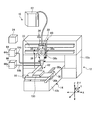
- FIG. 1 is a schematic diagram showing a schematic configuration of a laser processing apparatus according to an embodiment of the present invention.
- FIG. 2 is a schematic diagram showing a schematic configuration of the laser processing head shown in FIG.
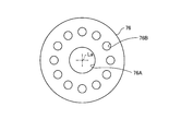
- FIG. 3 is a view taken along the line aa in FIG.
- FIG. 4 is another example of the aa arrow view in FIG.
- FIG. 5 is a schematic diagram showing a schematic configuration of another example of the laser processing apparatus according to the embodiment of the present invention.
- FIG. 6 is a schematic diagram showing a schematic configuration of the laser processing head shown in FIG.
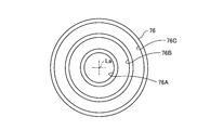
- FIG. 7 is a view taken along the line bb in FIG.
- FIG. 8 is another example of the view taken along the line bb in FIG.
- FIG. 1 is a schematic diagram showing a schematic configuration of a laser processing apparatus according to an embodiment of the present invention.
- FIG. 2 is a schematic diagram showing a schematic configuration of the laser processing head shown in FIG.
- FIG. 3 is a view taken along the line
- FIG. 9 is an explanatory diagram of the steps of the laser processing method according to the embodiment of the present invention.
- FIG. 10 is an explanatory diagram of the steps of the laser processing method according to the embodiment of the present invention.
- FIG. 11 is an explanatory diagram of the steps of the laser processing method according to the embodiment of the present invention.
- FIG. 12 is an explanatory diagram of a process of another example of the laser processing method according to the embodiment of the present invention.
- FIG. 13 is an explanatory diagram of a process of another example of the laser processing method according to the embodiment of the present invention.
- FIG. 14 is an explanatory diagram of a process of another example of the laser processing method according to the embodiment of the present invention.
- FIG. 1 is a schematic diagram showing a schematic configuration of a laser processing apparatus according to the present embodiment.
- FIG. 2 is a schematic diagram showing a schematic configuration of the laser processing head shown in FIG.
- FIG. 3 is a view taken along the line aa in FIG.
- FIG. 4 is another example of the aa arrow view in FIG.
- the laser processing apparatus 10 is an apparatus that performs various types of processing such as cutting and drilling on the workpiece 100.
- the laser processing apparatus 10 of this embodiment performs the cutting process in drilling. Further, the laser processing apparatus 10 also measures the workpiece 100.
- the laser processing apparatus 10 includes a frame 12, a moving unit 14, a stage unit 16, a laser processing unit 22 including a laser processing head 60, and a control unit 24.
- the laser processing apparatus 10 irradiates the processing object 100 held by the stage unit 16 with a laser beam by the laser processing unit 22 to laser process the processing object 100.
- the horizontal plane is the XY plane including the X-axis direction and the Y-axis direction orthogonal to the X-axis
- the direction orthogonal to the horizontal plane is the Z-axis direction.
- the direction rotating around the Y axis is defined as the ⁇ Y direction.
- the frame 12 is a housing of the laser processing apparatus 10 and is fixed to an installation surface such as the ground or a base.
- the frame 12 has a gate 12a and a base 12b inserted into the space of the gate 12a.
- the fixed part of the moving unit 14 is fixed to the frame 12. Therefore, in the laser processing apparatus 10 of the present embodiment, the moving unit 14 is fixed to the gate 12a and the base 12b of the frame 12, and the processing object 100 and the laser processing unit 22 are relatively moved by the moving unit 14. This is a so-called gate-type processing device.
- the moving unit 14 moves the workpiece 100 and the laser processing head 60 relative to each other.
- the moving unit 14 includes a Y-axis moving mechanism 30, an X-axis moving mechanism 34, a Z-axis moving mechanism 38, and a ⁇ Y rotating mechanism 39.
- the Y-axis moving mechanism 30 includes a rail 30a that is disposed on the base 12b of the frame 12 and extends in the Y-axis direction, and a Y-axis moving member 30b that moves along the rail 30a. In the Y-axis moving mechanism 30, the stage unit 16 is fixed to the Y-axis moving member 30b.
- the Y-axis moving mechanism 30 moves the stage unit 16 in the Y-axis direction by moving the Y-axis moving member 30b along the rail 30a.
- the Y-axis moving mechanism 30 can use various mechanisms as a mechanism for moving the Y-axis moving member 30b in the Y-axis direction. For example, a mechanism in which a ball screw is inserted into the Y-axis moving member 30b and the ball screw is rotated by a motor, a linear motor mechanism, a belt mechanism, or the like can be used. Similarly, various mechanisms can be used for the X-axis moving mechanism 34 and the Z-axis moving mechanism 38.
- the X-axis moving mechanism 34 includes a rail 33 that is disposed on the gate 12a of the frame 12 and extends in the X-axis direction, and an X-axis moving member 34a that moves along the rail 33.
- a Z axis moving mechanism 38 is fixed to an X axis moving member 34a.
- the X-axis moving mechanism 34 moves the Z-axis moving mechanism 38 in the X-axis direction by moving the X-axis moving member 34 a along the rail 33.
- the Z-axis moving mechanism 38 includes a rail 38a that is fixed to the X-axis moving member 34a and extends in the Z-axis direction, and a Z-axis moving member 38b that moves along the rail 38a.
- the ⁇ Y rotating mechanism 39 is fixed to the Z-axis moving member 38b.
- the Z-axis moving mechanism 38 moves the ⁇ Y rotating mechanism 39 in the Z-axis direction by moving the ⁇ Y rotating mechanism 39 along the rail 38a.
- the ⁇ Y rotation mechanism 39 is fixed to the Z-axis moving member 38b, and the laser processing head 60 is fixed.
- the ⁇ Y rotation mechanism 39 rotates the laser processing head 60 in the ⁇ Y direction by rotating the laser processing head 60 in the ⁇ Y direction with respect to the Z-axis moving member 38b.
- the moving unit 14 uses the Y-axis moving mechanism 30, the X-axis moving mechanism 34, and the Z-axis moving mechanism 38 to move the workpiece 100 and the laser processing head 60 in the X-axis direction, the Y-axis direction, and the Z-axis direction. Move relative to each other. Further, the moving unit 14 rotates the laser processing head 60 with respect to the processing object 100 using the ⁇ Y rotation mechanism 39. Thereby, the direction of the laser irradiated to the workpiece 100 from the laser processing head 60 can be adjusted.
- the moving unit 14 may include a mechanism for rotating the laser processing head 60 around the X axis. Further, a mechanism for adjusting the direction of laser irradiation may be provided in the laser processing head 60.
- the stage unit 16 is disposed on the Y-axis moving member 30b of the Y-axis moving mechanism 30.
- the stage unit 16 is a stage that supports the workpiece 100.
- the member integrated with the Y-axis moving member 30b that is, the Y-axis moving member 30b is used as the stage of the stage unit 16, but another support member is provided on the Y-axis moving member 30b. It may be provided as a stage.
- the stage unit 16 serves as a stage moving mechanism 42 that causes the Y-axis moving mechanism 30 to move the workpiece 100.
- the stage unit 16 includes a fixing mechanism that fixes the workpiece 100 at a predetermined position of the Y-axis moving member 30b.
- the stage unit 16 may further include an adjustment mechanism that adjusts the orientation of the workpiece 100 relative to the Y-axis moving member 30b, that is, the posture, as the stage moving mechanism 42.
- an adjustment mechanism that adjusts the orientation of the workpiece 100 relative to the Y-axis moving member 30b, that is, the posture, as the stage moving mechanism 42.
- a mechanism for rotating the workpiece 100 may be provided as the stage moving mechanism 42.
- the laser processing unit 22 includes a laser processing head 60, a laser light source 62, an assist gas supply unit 64, and a refrigerant supply unit 66.
- the laser light source 62 includes a fiber laser output device that outputs a laser using an optical fiber as a medium.
- a fiber laser output device for example, a Fabry-Perot type fiber laser output device or a ring type fiber laser output device can be used, and the laser is oscillated when these output devices are excited.
- the fiber of the fiber laser output device for example, silica glass to which a rare earth element such as erbium (Er), neodymium (Nd), ytterbium (Yb) is added can be used.
- a laser that performs nanosecond order pulse oscillation such as a YAG laser or a YVO4 laser can be used as the fiber laser.
- the laser light source 62 includes a short pulse laser output device that outputs a laser with a short pulse, for example, a frequency of 20 kHz.
- a short pulse laser output device for example, a titanium sapphire laser can be used as a laser oscillation source, and a pulse having a pulse width of 100 picoseconds or less can be oscillated.
- the short pulse laser outputs the laser with a short pulse having a pulse width of 100 nanoseconds or less.
- the short pulse laser is preferably a short pulse having a pulse width of 10 nanoseconds or more, and more preferably a laser having a pulse width of less than 1 nanosecond.
- Assist gas supply means 64 supplies assist gas to the laser processing head 60.
- the assist gas supply means 64 includes an assist gas supply unit 64a and an assist gas supply pipe 64b.
- the assist gas supply unit 64a pumps the assist gas from the assist gas storage tank in which the assist gas is stored to the assist gas supply pipe 64b by a compressor or the like.
- the assist gas supply pipe 64b is connected to the laser processing head 60, and supplies the assist gas pumped by the assist gas supply unit 64a to the laser processing head 60.
- an inert gas that is a dry gas such as air, nitrogen gas, oxygen gas, argon gas, xenon gas, helium gas, or a mixed gas thereof is used.
- the refrigerant supply means 66 supplies the refrigerant to the laser processing head 60.
- the refrigerant supply means 66 includes a refrigerant supply unit 66a and a refrigerant supply pipe 66b.
- the refrigerant supply unit 66a pumps the refrigerant from the refrigerant storage tank in which the refrigerant is stored to the refrigerant supply pipe 66b by a compressor or the like.
- the refrigerant supply pipe 66b is connected to the laser processing head 60, and supplies the refrigerant pumped by the refrigerant supply unit 66a to the laser processing head 60.
- the refrigerant for example, dry ice particles of about -80 ° C., carbon dioxide gas, liquid nitrogen, or the like is applied.
- the laser processing head 60 receives the laser output from the laser light source 62 and irradiates the processing target object 100 with the incident laser, thereby laser processing the processing target object 100.
- the laser output from the laser light source 62 is guided to the laser processing head 60 by an optical member that guides laser light such as an optical fiber.
- the laser processing head 60 includes a casing 72, a condensing optical system 74, and a nozzle 76, as shown in FIG.
- the casing 72 receives a laser output from the laser light source 62 and houses a scanning mechanism (not shown) for guiding the laser to the condensing optical system 74 together with the condensing optical system 74.
- the condensing optical system 74 has a plurality of lenses (one in the figure), condenses the laser L by the plurality of lenses, and sets the predetermined focal length and depth to the processing object 100.
- a laser L having a spot diameter of 2 is irradiated.
- the nozzle 76 is attached to the tip of the casing 72 where the condensing optical system 74 is disposed, and is formed in a cylindrical shape so as to allow the laser L condensed by the condensing optical system 74 to pass therethrough.
- the nozzle 76 is formed in a hollow conical shape whose diameter gradually decreases as the laser L converges toward the front side in the traveling direction of the laser L.
- the nozzle 76 has a laser irradiation nozzle 76A and a refrigerant injection nozzle 76B.
- the laser irradiation nozzle 76A is for passing the laser L condensed by the condensing optical system 74 and irradiating the processing object 100 with the laser L. It is a through hole.
- the laser irradiation nozzle 76A is connected to the assist gas supply pipe 64b of the assist gas supply means 64, and jets the assist gas A together with the laser L along the traveling direction of the laser L passing through the laser irradiation nozzle 76A.
- the processing speed for the processing object 100 such as metal can be further improved.
- the assist gas A is a nitrogen gas, an argon gas, or the like that suppresses the formation of an oxide film as a heat-affected layer that affects heat
- the processing accuracy for the workpiece 100 such as metal can be further improved.
- the gas type and mixing ratio of the assist gas A, the ejection amount (injection pressure) from the laser irradiation nozzle 76A, and the like can be changed according to the processing conditions such as the type of the processing object 100 and the processing mode.
- the refrigerant injection nozzle 76B is independently arranged outside the laser irradiation nozzle 76A.
- the coolant injection nozzle 76B is, for example, a hole formed in an annular shape coaxially with the optical axis La of the laser L so as to surround the laser irradiation nozzle 76A as shown in FIG. 3, or the laser L as shown in FIG.
- the refrigerant injection nozzle 76B is connected to the refrigerant supply pipe 66b of the refrigerant supply means 66, and injects the refrigerant R outside the laser L along the traveling direction of the laser L passing through the laser irradiation nozzle 76A.
- the coolant R is sprayed outside the laser L along the traveling direction of the laser L, so that the periphery of the processing portion of the processing object 100 by the laser L is cooled, and the heat of the processing object 100 by the laser L is cooled. The influence can be suppressed.
- the ejection amount (injection pressure) of the refrigerant R from the refrigerant injection nozzle 76B can be changed according to the processing conditions such as the type of the processing object 100 and the processing mode.
- the laser processing unit 22 may include a camera having a photographing means for photographing an image at a position where the laser is irradiated, for example, a CCD (Charge Coupled Device) image sensor. Thereby, the irradiation position of a laser, etc. can be adjusted based on the acquired image.
- a camera having a photographing means for photographing an image at a position where the laser is irradiated for example, a CCD (Charge Coupled Device) image sensor.
- CCD Charge Coupled Device
- the laser processing unit 22 opens a through hole by irradiating the processing object 100 with the laser output from the laser light source 62 from the laser processing head 60. Moreover, the laser processing unit 22 can cut the processing object 100 with a line by moving the irradiation position of the laser L, and can also cut the processing object 100.
- the control unit 24 controls operations of the moving unit 14, the stage unit 16, the laser processing unit 22, the assist gas supply unit 64a, and the refrigerant supply unit 66a.
- the control unit 24 controls the operation of the stage moving mechanism 42 of the moving unit 14 and the stage unit 16 to move the workpiece 100 and the laser processing head 60 relative to each other. Further, the control unit 24 controls driving of the laser processing unit 22 and irradiates the processing object 100 with the laser L. Further, the control unit 24 controls driving of the assist gas supply unit 64a to control supply of the assist gas A, injection pressure of the assist gas A from the laser irradiation nozzle 76A, and the like. Further, the control unit 24 controls driving of the refrigerant supply unit 66a to control supply of the refrigerant R, injection pressure of the refrigerant R from the refrigerant injection nozzle 76B, and the like.
- the laser processing apparatus 10 has a cylindrical laser irradiation nozzle 76A that passes the laser L irradiated from the condensing optical system 74 and a traveling direction of the laser L that passes the laser irradiation nozzle 76A.
- An assist gas supply means 64 for injecting the assist gas A from the laser irradiation nozzle 76A along the ring, an annular refrigerant injection nozzle 76B arranged coaxially with the laser L outside the laser irradiation nozzle 76A, and a laser irradiation nozzle.
- Refrigerant supply means 66 for injecting the refrigerant R from the refrigerant injection nozzle 76B along the traveling direction of the laser L passing through 76A.
- the laser processing apparatus 10 of the present embodiment has a cylindrical laser irradiation nozzle 76A that allows the laser L irradiated from the condensing optical system 74 to pass through, and a traveling direction of the laser L that passes the laser irradiation nozzle 76A.
- the laser processing apparatus 10 processes the workpiece 100 by irradiating the workpiece 100 with the laser L passing through the laser irradiation nozzle 76A.
- the refrigerant R is injected from the refrigerant injection nozzle 76B outside the laser L along the traveling direction of the laser L, the part to be processed by the laser L of the workpiece 100 is cooled.
- the assist gas A is jetted together with the laser L along the traveling direction of the laser L passing through the laser irradiation nozzle 76A, thereby preventing interference between the laser L and the refrigerant R, and moisture in the atmosphere is frozen by the refrigerant R. Even if it is solidified, it is prevented from being vaporized by the heat of the laser L and generating white smoke. As a result, the refrigerant R can be supplied to the processing portion of the processing object 100 without affecting the laser L.
- the laser irradiation nozzle 76A is formed with a through hole having an inner diameter having a gap with the laser L so that the passing laser L does not come in contact, and the assist gas supply means 64 has the gap It is preferable to supply the assist gas A to the through hole so as to satisfy the above condition. Thereby, since the assist gas A is injected so as to surround the laser L, the effect of preventing the interference between the laser L and the refrigerant R can be obtained remarkably.
- the relationship between the injection pressure P1 of the assist gas A injected from the laser irradiation nozzle 76A and the injection pressure P2 of the refrigerant R injected from the refrigerant injection nozzle 76B is P2 ⁇ P1. It is preferable to set.
- the setting of the injection pressure P1 of the assist gas A and the injection pressure P2 of the refrigerant R is performed by controlling the driving of the assist gas supply unit 64a and the refrigerant supply unit 66a by the control unit 24.
- the distance W from the focal point F of the laser L on the innermost side of the injection range of the coolant R is 0 on the processing surface 100 a of the processing object 100. It is preferable to be in the range of 1 mm or more and 50 mm or less. When the thickness is 0.1 mm or more, the effect of preventing interference between the laser L and the refrigerant R can be obtained favorably, and when the thickness is 50 mm or less, the effect of cooling the processing site can be favorably obtained. In order to set such a distance W, an angle along the laser L in the refrigerant injection nozzle 76B is set.
- the irradiation position of the laser L is moved along the processing surface 100a of the processing object 100 (processing process). May not be performed on the front side in the moving direction of the laser L but only on the rear side (refrigerant injection step). That is, even if the refrigerant R is injected to the front side in the moving direction of the laser L, there is no thermal influence of the laser L (before the thermal influence occurs), and this is not effective. Only the rear side in the moving direction of the laser L is assumed.
- the refrigerant injection nozzle 76B has a plurality of holes arranged in an annular shape so as to surround the laser irradiation nozzle 76A, and has an on-off valve that selectively supplies the refrigerant R to each hole. This can be realized by providing the switching mechanism.
- another coolant injection nozzle may be provided so that the coolant R can be further injected from the surface opposite to the processing surface 100a of the processing object 100 irradiated with the laser L.
- the refrigerant is supplied to the other refrigerant injection nozzle by the refrigerant supply means 66 described above. By doing in this way, the cooling efficiency of the process site
- FIG. 5 is a schematic diagram showing a schematic configuration of another example of the laser processing apparatus according to the embodiment of the present invention.
- FIG. 6 is a schematic diagram showing a schematic configuration of the laser processing head shown in FIG.
- FIG. 7 is a view taken along the line bb in FIG.
- FIG. 8 is another example of the view taken along the line bb in FIG.
- the laser processing apparatus 110 of another example is different from the laser processing apparatus 10 described with reference to FIGS. 1 and 2 with a shield gas supply means 68 and a shield gas injection nozzle 76C. And the other configurations are the same. Therefore, in the description of the laser processing apparatus 110 of another example, the same parts as those of the laser processing apparatus 10 described above are denoted by the same reference numerals and description thereof is omitted.
- the shield gas supply means 68 supplies shield gas to the laser processing head 60.
- the shield gas supply means 68 includes a shield gas supply unit 68a and a shield gas supply pipe 68b. Although not clearly shown in the drawing, the shield gas supply unit 68a pumps the shield gas to the shield gas supply pipe 68b by a compressor or the like from a shield gas storage tank in which the shield gas is stored.
- the shield gas supply pipe 68b is connected to the laser processing head 60, and supplies the shield gas pumped by the shield gas supply unit 68a to the laser processing head 60.
- an inert gas that is a dry gas such as air, nitrogen gas, oxygen gas, argon gas, xenon gas, helium gas, or a mixed gas thereof is used.
- the shield gas injection nozzle 76 ⁇ / b> C is provided in the nozzle 76.
- the shield gas injection nozzle 76C is independently arranged outside the laser irradiation nozzle 76A and outside the refrigerant injection nozzle 76B. That is, the shield gas injection nozzle 76C is disposed on the outermost side with respect to the laser irradiation nozzle 76A and the refrigerant injection nozzle 76B.
- the shield gas injection nozzle 76C is, for example, a hole formed in an annular shape coaxially with the optical axis La of the laser L so as to surround the refrigerant injection nozzle 76B as shown in FIG. 7, or a laser as shown in FIG.
- the laser irradiation nozzle 76A is shown as having the same configuration as that shown in FIG. 3, but it may be the same as that shown in FIG.
- This shield gas injection nozzle 76C is connected to the shield gas supply pipe 68b of the shield gas supply means 68, and shield gas is provided outside the laser L and inside the refrigerant R along the traveling direction of the laser L passing through the laser irradiation nozzle 76A. S is injected.
- the control unit 24 controls operations of the moving unit 14, the stage unit 16, the laser processing unit 22, the assist gas supply unit 64a, the refrigerant supply unit 66a, and the shield gas supply unit 68a.
- the control unit 24 controls the operation of the stage moving mechanism 42 of the moving unit 14 and the stage unit 16 to move the workpiece 100 and the laser processing head 60 relative to each other. Further, the control unit 24 controls driving of the laser processing unit 22 and irradiates the processing object 100 with the laser L. Further, the control unit 24 controls driving of the assist gas supply unit 64a to control supply of the assist gas A, injection pressure of the assist gas A from the laser irradiation nozzle 76A, and the like.
- control unit 24 controls driving of the refrigerant supply unit 66a to control supply of the refrigerant R, injection pressure of the refrigerant R from the refrigerant injection nozzle 76B, and the like. Further, the control unit 24 controls driving of the shield gas supply unit 68a to control supply of the shield gas S, injection pressure of the shield gas S from the shield gas injection nozzle 76C, and the like.
- the laser processing apparatus 110 has a cylindrical laser irradiation nozzle 76A that passes the laser L irradiated from the condensing optical system 74 and a traveling direction of the laser L that passes the laser irradiation nozzle 76A.
- the refrigerant supply means 66 for injecting the refrigerant R from the refrigerant injection nozzle 76B along the direction and the outside of the laser irradiation nozzle 76A and the outside of the refrigerant injection nozzle 76B are independently arranged coaxially with the laser L.
- An annular shield gas injection nozzle 76C and a laser L passing through the laser irradiation nozzle 76A are aligned along the traveling direction of the laser L.
- the laser processing apparatus 110 has a cylindrical laser irradiation nozzle 76A that allows the laser L irradiated from the condensing optical system 74 to pass therethrough and a traveling direction of the laser L that passes the laser irradiation nozzle 76A.
- the assist gas supply means 64 for injecting the assist gas A from the laser irradiation nozzle 76A, the refrigerant injection nozzle 76B arranged independently outside the laser irradiation nozzle 76A, and the laser irradiation nozzle 76A.
- a shield gas injection nozzle 76C composed of a hole and a laser L that passes through the laser irradiation nozzle 76A are aligned along the traveling direction of the laser L.
- the laser processing apparatus 110 processes the processing object 100 by irradiating the processing object 100 with the laser L passing through the laser irradiation nozzle 76A.
- the refrigerant R is injected from the refrigerant injection nozzle 76B outside the laser L along the traveling direction of the laser L, the part to be processed by the laser L of the workpiece 100 is cooled.
- the shielding gas S is injected outside the refrigerant R, interference between the refrigerant R and the atmosphere is prevented, and a situation in which moisture in the atmosphere freezes and solidifies due to the refrigerant R is prevented.
- the refrigerant R can be supplied to the processing portion of the processing object 100 without affecting the laser L.
- the assist gas A is jetted together with the laser L along the traveling direction of the laser L passing through the laser irradiation nozzle 76A, interference between the laser L and the refrigerant R is further prevented. Even if it freezes and solidifies, it is prevented from being vaporized by the heat of the laser L and generating white smoke. As a result, the refrigerant R can be supplied to the processing portion of the processing object 100 without affecting the laser L.
- the laser irradiation nozzle 76A is formed with a through hole having an inner diameter having a gap with the laser L so that the passing laser L does not come in contact, and the assist gas supply means 64 has the gap It is preferable to supply the assist gas A to the through hole so as to satisfy the above condition. Thereby, since the assist gas A is injected so as to surround the laser L, the effect of preventing the interference between the laser L and the refrigerant R can be obtained remarkably.
- the relationship between the injection pressure P2 of the refrigerant R injected from the refrigerant injection nozzle 76B and the injection pressure P3 of the shield gas S injected from the shield gas injection nozzle 76C is expressed as P2> P3. It is preferable to set to.
- the setting of the injection pressure P3 of the shield gas S and the injection pressure P2 of the refrigerant R is performed by controlling the drive of the shield gas supply unit 68a and the refrigerant supply unit 66a by the control unit 24.
- the relationship is preferably set to P1 ⁇ P2> P3, and the refrigerant R is also prevented from being mixed into the assist gas A, so that the effect of preventing the interference between the laser L and the refrigerant R can be obtained remarkably.
- the distance W from the focal point F of the laser L on the innermost side of the injection range of the coolant R is 0 on the processing surface 100a of the processing object 100. It is preferable to be in the range of 1 mm or more and 50 mm or less. When the thickness is 0.1 mm or more, the effect of preventing interference between the laser L and the refrigerant R can be obtained favorably, and when the thickness is 50 mm or less, the effect of cooling the processing site can be favorably obtained. In order to set such a distance W, an angle along the laser L in the refrigerant injection nozzle 76B is set.
- the irradiation position of the laser L is moved along the processing surface 100a of the processing object 100 (processing process). May not be performed on the front side in the moving direction of the laser L but only on the rear side (refrigerant injection step). That is, even if the refrigerant R is injected to the front side in the moving direction of the laser L, there is no thermal influence of the laser L (before the thermal influence occurs), and this is not effective. Only the rear side in the moving direction of the laser L is assumed.
- the refrigerant injection nozzle 76B has a plurality of holes arranged in an annular shape so as to surround the laser irradiation nozzle 76A, and has an on-off valve that selectively supplies the refrigerant R to each hole. This can be realized by providing the switching mechanism.
- another coolant injection nozzle may be provided so that the coolant R can be further injected from the surface opposite to the processing surface 100a of the processing object 100 irradiated with the laser L.
- the refrigerant is supplied to the other refrigerant injection nozzle by the refrigerant supply means 66 described above. By doing in this way, the cooling efficiency of the process site
- FIGS. 9 to 11 are explanatory diagrams of steps of the laser processing method according to the present embodiment.
- the laser processing method of the present embodiment is a processing method in the case where the processing object 100 is cut by a predetermined cutting line CL1 with a laser L as shown in FIGS.
- the workpiece 100 is cut by irradiating the laser L onto the preliminary cutting line CL2 along the cutting line CL1 while leaving the cutting line CL1.
- processing is performed by irradiating laser L onto the cutting line CL1 while injecting the coolant R toward the cut surface of the preliminary cutting line CL2 in the preliminary processing step.
- the object 100 is cut.
- the laser L is irradiated toward the thickness D direction of the workpiece 100, and the depth direction in the figure is the traveling direction.
- an injection nozzle is provided so that the injection position can be moved in the thickness D direction as the laser L moves the focal point of the workpiece 100 in the thickness D direction. It is preferable that an injection nozzle is provided so that the injection position can be moved in the traveling direction as L progresses.
- the injection direction of the refrigerant R may be a direction orthogonal to the cut surface of the preliminary cutting line CL2, or may be a direction inclined to the cutting surface of the preliminary cutting line CL2.
- the processing object 100 is cut by irradiating the laser L onto the preliminary cutting line CL2 along the cutting line CL1 while leaving the cutting line CL1, and the cutting surface of the preliminary cutting line CL2 is cut.
- the coolant R applies the processing object 100 to the processing site. Thermal effects can be suppressed.
- the refrigerant R can be supplied to the processing portion of the processing object 100 without affecting the laser L.
- the laser L when the thickness D of the workpiece 100 is large, the laser L must be irradiated for a long time before penetrating the thickness D of the workpiece 100, but the thermal effect on the workpiece is significant.
- the preliminary cutting line CL2 is set and cut within a range in which no thermal influence is generated on the processing portion of the cutting line CL1, and then the refrigerant R is injected from the cut surface side of the preliminary cutting line CL2.
- the cutting since the cutting is performed on the cutting line CL1, it is effective to suppress the thermal influence on the processing site when cutting the cutting line CL1.
- the distance H of the preliminary cutting line CL2 from the cutting line CL1 is set.
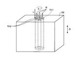
- FIGS. 12 to FIG. 14 are explanatory diagrams of processes of another example of the laser processing method according to the present embodiment.
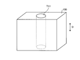
- the laser processing method of the present embodiment is a processing method in the case where a predetermined through hole TH1 is cut in the workpiece 100 by the laser L, as shown in FIGS.
- a preliminary through hole TH2 having a diameter smaller than the diameter of the through hole TH1 is cut within the range of the through hole TH1.
- the preliminary through hole TH2 may be plural or single.
- the through hole TH1 is cut by the laser L while jetting the coolant R into the preliminary through hole TH2 in the preliminary machining step.
- the laser L is irradiated toward the thickness D direction of the workpiece 100, and the circumferential direction of the through hole TH1 is the traveling direction.
- the injection of the refrigerant R is performed along the traveling direction of the laser L. Further, the refrigerant R may be injected from the direction opposite to the irradiation direction of the laser L, that is, from the opening on the opposite side of the preliminary through hole TH2.
- the preliminary through-hole TH2 having a diameter smaller than the diameter of the through-hole TH1 is cut in the range of the through-hole TH1, and the coolant R is injected into the preliminary through-hole TH2 while the through-hole TH1 is formed.
- the refrigerant R can suppress the thermal influence on the processing part of the processing object 100.
- the refrigerant R can be supplied to the processing portion of the processing object 100 without affecting the laser L.
- the position of the preliminary through hole TH2 is set and cut within a range in which no thermal influence is generated on the processed portion of the through hole TH1, and then the refrigerant R is injected into the preliminary through hole TH2.
- the through-hole TH1 is cut, it is effective to suppress the thermal influence on the machining site when the through-hole TH1 is cut.
- the intensity of the laser L and the object to be machined Considering the material of 100, the distance of the preliminary through hole TH2 from the cutting line along the peripheral surface of the through hole TH1 is set.
- the workpiece 100 is a carbon fiber reinforced plastic (CFRP: Carbon Fiber Reinforced Plastic), or a metal material such as carbon fiber reinforced plastic and titanium, which is easily affected by laser L processing. It is preferable to apply a superposition of and.
- CFRP Carbon Fiber Reinforced Plastic
- the coolant R can be supplied to the workpiece of the workpiece without affecting the laser L when the coolant R cools the workpiece. .
Landscapes
- Engineering & Computer Science (AREA)
- Physics & Mathematics (AREA)
- Optics & Photonics (AREA)
- Plasma & Fusion (AREA)
- Mechanical Engineering (AREA)
- Laser Beam Processing (AREA)
Applications Claiming Priority (2)
| Application Number | Priority Date | Filing Date | Title |
|---|---|---|---|
| JP2016133475A JP6746407B2 (ja) | 2016-07-05 | 2016-07-05 | レーザ加工装置およびレーザ加工方法 |
| JP2016-133475 | 2016-07-05 |
Publications (1)
| Publication Number | Publication Date |
|---|---|
| WO2018008400A1 true WO2018008400A1 (ja) | 2018-01-11 |
Family
ID=60912582
Family Applications (1)
| Application Number | Title | Priority Date | Filing Date |
|---|---|---|---|
| PCT/JP2017/022833 Ceased WO2018008400A1 (ja) | 2016-07-05 | 2017-06-21 | レーザ加工装置およびレーザ加工方法 |
Country Status (2)
| Country | Link |
|---|---|
| JP (1) | JP6746407B2 (https=) |
| WO (1) | WO2018008400A1 (https=) |
Cited By (6)
| Publication number | Priority date | Publication date | Assignee | Title |
|---|---|---|---|---|
| CN112658670A (zh) * | 2020-12-02 | 2021-04-16 | 江苏普瑞亚动力科技有限公司 | 用于柴油发动机装配的激光辅助校准工艺 |
| CN113894444A (zh) * | 2021-09-28 | 2022-01-07 | 武汉大学 | 一种基于干涉光路设计的水导脉冲激光加工系统及方法 |
| US11597035B2 (en) * | 2019-09-20 | 2023-03-07 | Shanghai Institute Of Optics And Fine Mechanics, Chinese Academy Of Sciences | Debris-free laser ablation processing assisted by condensed frost layer |
| DE102022209031A1 (de) | 2022-08-31 | 2024-02-29 | Fraunhofer-Gesellschaft zur Förderung der angewandten Forschung eingetragener Verein | Bearbeitungskopf und Verfahren zum Laserstrahlschneiden von Bauteilen |
| US12017304B2 (en) | 2021-12-23 | 2024-06-25 | Saudi Arabian Oil Company | Laser switching apparatus and method |
| DE112019003160B4 (de) | 2019-04-25 | 2025-03-13 | Shufeng Sun | Kombinierter Laserbearbeitungskopf mit einem durch einen Spritzflüssigkeitsstrahl selbst erzeugten Schleifkornstrom und Verfahren zu dessen Betrieb |
Citations (4)
| Publication number | Priority date | Publication date | Assignee | Title |
|---|---|---|---|---|
| JPS6160757B2 (https=) * | 1981-02-06 | 1986-12-22 | Amada Eng & Service | |
| JPH08141768A (ja) * | 1994-11-16 | 1996-06-04 | Amada Co Ltd | レーザー加工装置の加工ヘッド |
| JP2010247206A (ja) * | 2009-04-17 | 2010-11-04 | Muneharu Kutsuna | 複合材料のレーザ加工法 |
| JP2014161903A (ja) * | 2013-02-27 | 2014-09-08 | Mitsubishi Heavy Ind Ltd | 加工装置、加工方法 |
-
2016
- 2016-07-05 JP JP2016133475A patent/JP6746407B2/ja not_active Expired - Fee Related
-
2017
- 2017-06-21 WO PCT/JP2017/022833 patent/WO2018008400A1/ja not_active Ceased
Patent Citations (4)
| Publication number | Priority date | Publication date | Assignee | Title |
|---|---|---|---|---|
| JPS6160757B2 (https=) * | 1981-02-06 | 1986-12-22 | Amada Eng & Service | |
| JPH08141768A (ja) * | 1994-11-16 | 1996-06-04 | Amada Co Ltd | レーザー加工装置の加工ヘッド |
| JP2010247206A (ja) * | 2009-04-17 | 2010-11-04 | Muneharu Kutsuna | 複合材料のレーザ加工法 |
| JP2014161903A (ja) * | 2013-02-27 | 2014-09-08 | Mitsubishi Heavy Ind Ltd | 加工装置、加工方法 |
Cited By (7)
| Publication number | Priority date | Publication date | Assignee | Title |
|---|---|---|---|---|
| DE112019003160B4 (de) | 2019-04-25 | 2025-03-13 | Shufeng Sun | Kombinierter Laserbearbeitungskopf mit einem durch einen Spritzflüssigkeitsstrahl selbst erzeugten Schleifkornstrom und Verfahren zu dessen Betrieb |
| US11597035B2 (en) * | 2019-09-20 | 2023-03-07 | Shanghai Institute Of Optics And Fine Mechanics, Chinese Academy Of Sciences | Debris-free laser ablation processing assisted by condensed frost layer |
| CN112658670A (zh) * | 2020-12-02 | 2021-04-16 | 江苏普瑞亚动力科技有限公司 | 用于柴油发动机装配的激光辅助校准工艺 |
| CN113894444A (zh) * | 2021-09-28 | 2022-01-07 | 武汉大学 | 一种基于干涉光路设计的水导脉冲激光加工系统及方法 |
| US12017304B2 (en) | 2021-12-23 | 2024-06-25 | Saudi Arabian Oil Company | Laser switching apparatus and method |
| DE102022209031A1 (de) | 2022-08-31 | 2024-02-29 | Fraunhofer-Gesellschaft zur Förderung der angewandten Forschung eingetragener Verein | Bearbeitungskopf und Verfahren zum Laserstrahlschneiden von Bauteilen |
| WO2024046813A1 (de) | 2022-08-31 | 2024-03-07 | Fraunhofer-Gesellschaft zur Förderung der angewandten Forschung e.V. | Bearbeitungskopf und verfahren zum laserstrahlschneiden von bauteilen |
Also Published As
| Publication number | Publication date |
|---|---|
| JP6746407B2 (ja) | 2020-08-26 |
| JP2018001243A (ja) | 2018-01-11 |
Similar Documents
| Publication | Publication Date | Title |
|---|---|---|
| WO2018008400A1 (ja) | レーザ加工装置およびレーザ加工方法 | |
| JP5364856B1 (ja) | 加工装置、加工方法 | |
| KR101626312B1 (ko) | 레이저 절단방법 및 레이저 절단장치 | |
| US10220469B2 (en) | Combined machining apparatus and combined machining method | |
| WO2013002165A1 (ja) | 脆性的な部材を切断する装置、方法、および切断された脆性的な部材 | |
| US20190176271A1 (en) | Laser machining device and laser machining method | |
| JP2007196373A (ja) | フライス及びレーザで材料を機械加工するための組み合わせ装置 | |
| JP6071640B2 (ja) | 加工装置、加工方法 | |
| JP2009511273A (ja) | レーザー切断/溶接のための方法及び装置 | |
| JP2014189478A (ja) | 強化ガラス板加工方法 | |
| KR20150116395A (ko) | 레이저 가공 장치 | |
| JP5873978B2 (ja) | レーザ加工方法、およびノズルの製造方法 | |
| KR20180070981A (ko) | 레이저 가공 장치 | |
| JP2012192420A (ja) | レーザ加工方法およびレーザ加工装置 | |
| WO2021200667A1 (ja) | コンクリートの表面処理方法、及び、レーザ処理済みコンクリート表面 | |
| JP6719231B2 (ja) | 炭素繊維複合材料の加工方法および加工装置 | |
| JP6348877B2 (ja) | 熱切断装置及び方法 | |
| KR20130022845A (ko) | 레이저 가공장치 | |
| JP4478251B2 (ja) | レーザとウォータジェットの複合加工装置 | |
| WO2021095253A1 (ja) | レーザ切断方法及びレーザ切断装置 | |
| JP4695363B2 (ja) | 単一ヘッド式レーザによる高スループットレーザショックピーニング | |
| JP2012066265A (ja) | レーザ加工方法 | |
| JP2000317661A (ja) | レーザビームによる切断方法および装置並びに原子炉廃炉を解体するときの黒鉛ブロックの切断方法 | |
| JP7684251B2 (ja) | 横型レーザ加工装置 | |
| JP6000101B2 (ja) | レーザー加工装置 |
Legal Events
| Date | Code | Title | Description |
|---|---|---|---|
| 121 | Ep: the epo has been informed by wipo that ep was designated in this application |
Ref document number: 17824007 Country of ref document: EP Kind code of ref document: A1 |
|
| NENP | Non-entry into the national phase |
Ref country code: DE |
|
| 122 | Ep: pct application non-entry in european phase |
Ref document number: 17824007 Country of ref document: EP Kind code of ref document: A1 |