WO2018003261A1 - 動作玩具 - Google Patents
動作玩具 Download PDFInfo
- Publication number
- WO2018003261A1 WO2018003261A1 PCT/JP2017/016276 JP2017016276W WO2018003261A1 WO 2018003261 A1 WO2018003261 A1 WO 2018003261A1 JP 2017016276 W JP2017016276 W JP 2017016276W WO 2018003261 A1 WO2018003261 A1 WO 2018003261A1
- Authority
- WO
- WIPO (PCT)
- Prior art keywords
- rack
- operation unit
- toy
- unit
- gear
- Prior art date
- Legal status (The legal status is an assumption and is not a legal conclusion. Google has not performed a legal analysis and makes no representation as to the accuracy of the status listed.)
- Ceased
Links
Images

Classifications
-
- A—HUMAN NECESSITIES
- A63—SPORTS; GAMES; AMUSEMENTS
- A63H—TOYS, e.g. TOPS, DOLLS, HOOPS OR BUILDING BLOCKS
- A63H29/00—Drive mechanisms for toys in general
-
- A—HUMAN NECESSITIES
- A63—SPORTS; GAMES; AMUSEMENTS
- A63H—TOYS, e.g. TOPS, DOLLS, HOOPS OR BUILDING BLOCKS
- A63H31/00—Gearing for toys
- A63H31/08—Gear-control mechanisms; Gears for imparting a reciprocating motion
Definitions
- the present invention relates to an operation toy having an operation unit capable of repetitive operation.
- Patent Document 1 reciprocates an arm member such as a robot toy.
- the operating rod is rotated, and the arm member is reciprocated according to the rotation of the operating rod.
- the object of the present invention is to provide a toy that can perform repetitive motions of the motion part and has excellent operability.
- An operation toy includes an operation unit capable of repetitive operation, an operation unit for operating the operation unit, and a transmission unit that transmits an operation of the operation unit to the operation unit as a repetitive operation.
- the transmission unit is arranged between the first rack and the second rack that are arranged with their tooth surfaces facing each other, and the first rack and the second rack, and rotates according to the operation of the operation unit.
- An intermittent gear having a notch tooth formed on a part of the circumference thereof that is moved and selectively engages with one of the first rack and the second rack according to rotation. When the operation unit is operated in one direction, the notch teeth are alternately engaged with the first rack and the second rack.
- the operation unit has a gear along an operation direction of the operation unit, and the intermittent gear has an operation unit side gear to which an operation of the operation unit is input. May be.
- the action toy according to claim 1 or 2 wherein a direction in which the operation unit is operated may be different from a direction of the repetitive action.
- a direction in which the operation unit is operated may be a linear direction.
- an adjustment gear may be provided between the operation gear and the operation unit side gear.
- the operating toy according to the present invention may further include a biasing member that biases the operation unit in a direction opposite to the operation direction of the operation unit.
- 1 and 2 show an example of a moving toy for explaining an embodiment of the present invention.
- Casing part 40 is divided into right and left casing parts 40a and 40b, and operation part 10, operation part 20, and transmission part 30 are stored between right and left casing parts 40a and 40b combined with each other.
- the operation unit 10 includes a cylindrical body part 11 disposed outside the casing part 40, and a connecting part 12 connected to one end of the body part 11 and accommodated inside the casing part 40.
- the connecting part 12 is divided into a connecting part right half 12a and a connecting part left half 12b in the left and right directions.
- the part 12sw is parallel to the axis CL, which is the central axis of the body part 11, and is appropriately supported on the inner wall surface of the casing part 40 so as to be slidable.
- drum 11 can be reciprocated along the axis line CL (it can move to the arrow X1 direction and the arrow X2 direction in the figure).
- the operation unit 10 may repeatedly operate on a predetermined locus.
- the operation unit 20 includes an operation unit main body 21 and a spring 25 as an urging member.
- the operation portion main body 21 is disposed behind the connecting portion 12 on the axis CL, and can be operated in a direction orthogonal to the axis CL (in the directions indicated by arrows Y1 and Y2 in the drawing) and provided in the casing portion 40.
- the leading end 21 e is accommodated inside the casing part 40 in a state of being arranged outside the casing part 40 through the cutout part 41.
- An operation unit rack 22 extending in the operable direction of the operation unit main body 21 is formed on one side surface of the operation unit main body 21 accommodated in the casing unit 40.
- the spring 25 is sandwiched between the lower wall surface 40 bw of the casing unit 40 and the inner wall 23 uw of the operation unit main body 21 in the operable direction of the operation unit main body 21, and can be extended and contracted in the operable direction of the operation unit main body 21. 49.
- the spring 25 is a direction (Y2 direction in the figure) opposite to the direction (arrow Y1 direction in the figure) in which the operation part body 21 is pushed toward the inside of the casing part 40 among the operable directions of the operation part body 21.
- the operation unit main body 21 is biased. Note that the operation portion main body 21 biased by the spring 25 is prevented from being detached from the casing portion 40 by, for example, engagement between an end surface of the operation portion rack 22 and an edge portion of the notch portion 41 or the like.
- the transmission unit 30 includes an operation unit rack 22 provided in the operation unit 20, a first rack 31 and a second rack 32 provided in the connection unit 12, and an operation unit rack 22, the first rack, and the second rack. And an intermittent gear 33 interposed therebetween.
- the first rack 31 and the second rack 32 are formed on the right half 12a of the connecting portion constituting the connecting portion 12, and are arranged so as to extend parallel to the axis CL and have tooth surfaces facing each other across the axis CL. Yes.
- the intermittent gear 33 includes an operation unit side pinion 33a to which an operation of the operation unit 20 is input, and a notch tooth 33b that outputs the operation of the operation unit 20 to the connecting unit 12, and includes the operation unit side pinion 33a and the notch.
- the teeth 33b are integrally formed with the intermittent gear shaft 33c as a rotation center.
- the notch teeth 33b are arranged between the first rack 31 and the second rack 32, and the tooth surfaces of the notch teeth 33b are formed in a part in the circumferential direction around the intermittent gear shaft 33c.
- the notch teeth 33b are selectively and alternately engaged with one of the first rack 31 and the second rack 32. .
- the adjustment gear 38 includes a small-diameter gear portion 38a and a large-diameter gear portion 38b that are integrally formed with an adjustment gear shaft 38c parallel to the intermittent gear shaft 33c as a rotation center, and the small-diameter gear portion 38a is provided in the operation unit rack 22.
- the large-diameter gear portion 38b is engaged with the operation portion side pinion 33a.
- the operation of the operation unit 20 is appropriately amplified by the gear ratio between the small-diameter gear unit 38a and the large-diameter gear unit 38b and the gear ratio between the large-diameter gear unit 38b and the operation unit side pinion 33a and transmitted to the notch teeth 33b.
- the intermittent gear shaft 33c and the adjustment gear shaft 38c are disposed so as to protrude from the left and right cutout portions 12ah and 12bh formed on the connecting portion 12 to the left and right outer sides of the connecting portion 12, and are provided on the side walls of the left and right casing portions 40a and 40b.
- the intermittent gear bearing portion 43 and the adjustment gear bearing portion 48 are rotatably supported.
- the operation unit 20 in a state before the operation unit 20 is operated, the operation unit 20 is biased by the spring 25, and the standby position P 0 where the tip end portion 21e protrudes from the casing portion 40 to the outermost side. Is arranged. Then, it is assumed that the operating unit 10 is in the most retracted state in the casing unit 40.
- FIG 4 (b) as shown in, when the operation unit 20 further pushed from the first position P 1, in accordance with the operation amount of the operation unit 20, the adjusting gear 38 engaged with the operating part rack 22 anti The intermittent gear 33 that is further rotated clockwise and engaged with the adjustment gear 38 is further rotated clockwise. Thereby, the notch teeth 33b are engaged with the second rack 32, and the operating portion 10 is pulled in (moved in the direction of arrow X2 in the figure).
- Figure 5 illustrates the operation of the operation portion 10 when the operating portion 20 is pushed by the maximum stroke from the standby position P 0.
- the operation unit 20 passes through the first position P 1 and the second position P 2 from the standby position P 0 and is further pushed from the second position P 2 by a predetermined operation amount ⁇ . It is pushed to 3 .
- FIG. 5B shows a state in which the operation unit 20 is pushed from the standby position P 0 to the first position P 1 , and a process in which the operation unit 20 is pushed to the first position P 1 is shown in detail in FIG. As described above, the notch teeth 33b engage with the first rack 31, and the operating portion 10 is protruded.
- FIG. 5 (c) shows a state where the operation unit 20 is pushed from the first position P 1 to the second position P 2, in the course of the operation unit 20 is pushed to the second position P 2, in detail in FIG. 4 As shown, the notch teeth 33b engage with the second rack 32, and the operating portion 10 is pulled.
- FIG. 5 (d) shows a state in which the operation unit 20 is pushed from the second position P 2 to a third position P 3, in the course of the operation unit 20 is pushed up to the third position P 3, the notch tooth 33b is The first rack 31 is engaged again, and the operation unit 10 is protruded.
- Figure 6 illustrates the operation of the operation portion 10 when the operating portion 20 is pushed in the maximum stroke is operated to the standby position P 0 again.
- the operation unit 20 is urged by a spring 25 in a direction opposite to the pushing direction (the direction of arrow Y1 in the figure) (the Y2 direction in the figure), and automatically according to the release from the pushing operation. It is pushed back toward the standby position P 0 from the third position P 3.
- FIG. 6 (b) is shows a state in which the operation unit 20 is pushed back from the third position P 3 to the second position P 2, in the course of the operation unit 20 is pushed back to the second position P 2, the notch tooth 33b is Engaging with the first rack 31, the operating unit 10 is drawn.
- FIG. 6 (c) shows a state where the operation unit 20 is pushed back from the second position P 2 to the first position P 1, in the course of the operation unit 20 is pushed back to the first position P 1, the notch tooth 33b is Engaging with the second rack 32, the operating portion 10 is protruded.
- Figure 6 (d) shows a state in which the operation unit 20 is pushed back from the first position P 1 to the standby position P 0, in the course of the operation unit 20 is pushed back to the standby position P 0, the notch tooth 33b is first again The first rack 31 is engaged, and the operating unit 10 is drawn.
- the notch teeth 33 b of the intermittent gear 33 are alternately engaged with the first rack 31 and the second rack 32 to operate the operation unit 10. Can be repeatedly operated, and the operability of the moving toy 1 can be enhanced.
- the operation unit 20 is pushed back by the spring 25, and the repetitive operation of the operation unit 10 can be repeated only by the operation of the operation unit 20 in the pushing direction (arrow Y1 direction in the figure).
- the operability of the moving toy 1 can be further enhanced.
- the notch teeth 33 b of the intermittent gear 33 are alternately engaged with the first rack 31 and the second rack 32, so that the notch teeth 33 b are the first rack 31 and the second rack 32. It means engaging with each of the racks 32 one or more times.
- the notch teeth 33 b are engaged with the first rack 31 twice and are engaged with the second rack 32 once. May be engaged with each of the first rack 31 and the second rack 32 once, or may be engaged with each of the first rack 31 and the second rack 32 a plurality of times. .
- the number of engagements between the notch teeth 33b and the first rack 31 and the second rack 32 in one direction operation of the operation unit 20, that is, the number of repetitive operations of the operation unit 10 in one direction operation of the operation unit 20 is as follows.
- the number of teeth of the operation unit rack 22, the gear ratio between the small diameter gear unit 38a and the large diameter gear unit 38b, and the gear ratio between the large diameter gear unit 38b and the operation unit side pinion 33a can be changed as appropriate.
- the action toy according to the present embodiment may be a figure toy such as a doll toy, a robot toy, or a weapon toy.
- a figure toy such as a doll toy, a robot toy, or a weapon toy.
- the operability and taste of the toy can be improved.
- the action toy of the present invention is not limited to the above-described embodiment, and appropriate modifications and improvements can be made.
- the operation unit 20 may be operated to rotate in one direction, or may be operated so as to be inclined in a curved direction in one direction.
- the operation direction of the operation unit 20 has been described as being a direction orthogonal to the axis line CL, but the present invention is not limited thereto.
- the operation direction of the operation unit 20 and the axis CL may be parallel or may intersect in a direction that is not orthogonal.
Landscapes
- Toys (AREA)
Abstract
【課題】操作部の一方向の操作で反復動作を行うことができる動作玩具を提供する。 【解決手段】動作玩具1は、反復動可能な動作部10と、動作部10を動作させるための操作部20と、操作部20の操作を反復動作として動作部10に伝達する伝達部30と、を備え、伝達部30は、互いに歯面を対向させて配置されており、動作部10と一体に動作する第1ラック31及び第2ラック32と、第1ラック31及び第2ラック32の間に配置されており、操作部20の操作に応じて回動され、回動に応じて第1ラック31及び第2ラック32のうち一方のラックと選択的に係合する切欠き歯33bが円周上の一部に形成された間欠歯車33と、を有し、操作部20が一方向に操作された際に、切欠き歯33bは、第1ラック31及び第2ラック32に交互に係合する。
Description
本発明は、反復動作可能な動作部を有する動作玩具に関する。
特許文献1に記載された作動装置はロボット玩具等の腕部材を往復動作させるものである。この作動装置では、操作杆が回転操作され、操作杆の回転に応じて腕部材が往復動作される。
特許文献1に開示された作動装置では、腕部材の一回の往復動作に対し、操作杆の回転操作として操作方向が互いに異なる正回転及び逆回転の二回の回転操作が必要である。このため、腕部材の往復動作の繰り返しには、多くの操作回数及び頻繁な操作方向の切り換えを要し、操作性が悪かった。
本発明は、動作部の反復動作を行うことができ、操作性に優れた動作玩具を提供することを目的とする。
本発明に係る動作玩具は、反復動作可能な動作部と、前記動作部を動作させるための操作部と、前記操作部の操作を反復動作として前記動作部に伝達する伝達部と、を備え、前記伝達部は、互いに歯面を対向させて配置された第1ラック及び第2ラックと、前記第1ラック及び前記第2ラックの間に配置されており、前記操作部の操作に応じて回動され、回動に応じて前記第1ラック及び前記第2ラックのうち一方のラックと選択的に係合する切欠き歯が円周上の一部に形成された間欠歯車と、を有し、前記操作部が一方向に操作された際に、前記切欠き歯が前記第1ラック及び前記第2ラックに交互に係合することを特徴とする。
また、本発明に係る動作玩具においては、前記操作部は、操作部の操作方向に沿った歯車を有し、前記間欠歯車は、前記操作部の操作が入力される操作部側歯車を有してもよい。
また、本発明に係る動作玩具においては、 請求項1乃至2に記載の動作玩具であって、前記操作部の操作される方向は、前記反復動作の方向と異なってもよい。
また、本発明に係る動作玩具においては、前記操作部の操作される方向は、直線方向であってもよい。
また、本発明に係る動作玩具においては、前記操作歯車と前記操作部側歯車との間に調整歯車を有してもよい。
また、本発明に係る動作玩具においては、前記操作部の操作方向とは反対方向に前記操作部を付勢する付勢部材をさらに備えてもよい。
本発明によれば、動作部の反復動作を行うことができ、操作性に優れた動作玩具を提供することができる。
図1及び図2は、本発明の実施形態を説明するための動作玩具の一例を示す。
図1及び図2に示す動作玩具1は、動作部10と、動作部10を動作させるための操作部20と、操作部20の操作を動作部10に伝達する伝達部30と、ケーシング部40とを備える。ケーシング部40は、左右ケーシング部40a,40bに二分されており、互いに組み合わされる左右ケーシング部40a,40bの間に動作部10、操作部20、及び伝達部30が収容される。
動作部10は、ケーシング部40の外部に配置される円柱状の胴部11と、胴部11の一端に接続されており且つケーシング部40の内部に収容される連結部12とを有する。連結部12は、連結部右半分12aと連結部左半分12bとに左右に二分されており、連結部右半分12a及び連結部左半分12bそれぞれの上面壁部12uw、下面壁部12dw及び側面壁部12swは、胴部11の中心軸線である軸線CLと平行とされ、ケーシング部40の内壁面に摺動可能に適宜支持されている。これにより、連結部12及び胴部11は軸線CLに沿って往復動作可能(図中、矢印X1方向及び矢印X2方向に移動可能)とされている。
なお、本実施形態においては、動作部10が往復動作をする場合について説明をするが、動作は往復動作に限らない。例えば、動作部10が所定の軌跡上を反復動作するものでも良い。
なお、本実施形態においては、動作部10が往復動作をする場合について説明をするが、動作は往復動作に限らない。例えば、動作部10が所定の軌跡上を反復動作するものでも良い。
操作部20は、操作部本体21と、付勢部材としてのバネ25とを有する。操作部本体21は、軸線CL上で連結部12の後方に配置されており、軸線CLと直交する方向(図中、矢印Y1方向及び矢印Y2方向)に操作可能に、且つケーシング部40に設けられた切り欠き部41を通して先端部21eがケーシング部40の外部に配置された状態でケーシング部40の内部に収容されている。そして、ケーシング部40の内部に収容されている操作部本体21の一側面には、操作部本体21の操作可能方向に延びる操作部ラック22が形成されている。
バネ25は、ケーシング部40の下壁面40bwと操作部本体21の内壁23uwとの間で操作部本体21の操作可能方向に挟み込まれており、操作部本体21の操作可能方向に伸縮可能に支柱49によって支持されている。バネ25は、操作部本体21の操作可能方向のうち、操作部本体21がケーシング部40の内部に向けて押し込まれる方向(図中、矢印Y1方向)とは反対方向(図中、Y2方向)に操作部本体21を付勢している。なお、バネ25によって付勢されている操作部本体21は、例えば操作部ラック22の端面と切り欠き部41の縁部との係合等により、ケーシング部40から抜け止めされている。
伝達部30は、操作部20に設けられている操作部ラック22と、連結部12に設けられている第1ラック31及び第2ラック32と、操作部ラック22と第1ラック及び第2ラック32との間に介在する間欠歯車33とを含む。
第1ラック31及び第2ラック32は、連結部12を構成する連結部右半分12aに形成されており、軸線CLに平行に延び且つ軸線CLを挟んで互いに歯面を対向させて配置されている。
間欠歯車33は、操作部20の操作が入力される操作部側ピニオン33aと、操作部20の操作を連結部12に出力する切欠き歯33bとを有し、操作部側ピニオン33a及び切欠き歯33bは、間欠歯車軸33cを回転中心として一体に構成されている。
切欠き歯33bは第1ラック31及び第2ラック32の間に配置されており、切欠き歯33bの歯面は間欠歯車軸33cを中心にして円周方向の一部に形成されている。間欠歯車33が間欠歯車軸33cまわりに一方向に回動された際には、切欠き歯33bは第1ラック31及び第2ラック32のうち一方のラックと選択的に且つ交互に係合する。
操作部側ピニオン33aには調整歯車38を介して操作部20の操作が入力される。調整歯車38は、間欠歯車軸33cと平行な調整歯車軸38cを回転中心として一体に構成されている小径歯車部38a及び大径歯車部38bを有し、小径歯車部38aが操作部ラック22に係合し、大径歯車部38bが操作部側ピニオン33aに係合している。操作部20の操作は、小径歯車部38aと大径歯車部38bとの歯車比、及び大径歯車部38bと操作部側ピニオン33aとの歯車比によって適宜増幅されて切欠き歯33bに伝達される。
間欠歯車軸33c及び調整歯車軸38cは、連結部12に形成された左右両側の切欠き部12ah、12bhから連結部12の左右外側に突出して配置され、左右ケーシング部40a,40bの側壁に設けられた間欠歯車軸受部43及び調整歯車軸受部48に回転可能にそれぞれ支持されている。
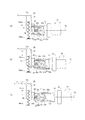
以下、図3から図6を参照して、動作玩具1の動作について説明する。
て説明する。
て説明する。
図3(a)に示すように、操作部20が操作される前の状態において、操作部20はバネ25に付勢され、先端部21eがケーシング部40から最も外側に突出した待機位置P0に配置されている。そして、動作部10は、ケーシング部40内に最も引き込まれた状態にあるものとする。
図3(b)に示すように、操作部20が押し込まれる(図中の矢印Y1方向に操作される)と、操作部20の操作に応じて、操作部ラック22に係合している調整歯車38が反時計回りに回動され、調整歯車38に係合している間欠歯車33が時計回りに回動される。これにより、切欠き歯33bが第1ラック31に係合し、動作部10が突き出される(図中、X1方向に移動される)。
図3(c)に示すように、操作部20が待機位置P0から所定の操作量Δだけ操作されて第1位置P1まで押し込まれると、切欠き歯33bの回転方向の最後端の歯面が第1ラック31との噛み合いから外れ、動作部10の突き出し動作が完了する。
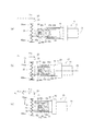
続いて、図4(a)に示すように、操作部20が第1位置P1まで押し込まれた状態で、切欠き歯33bの回転方向の最前端の歯面が第2ラック32に噛み合っている。
図4(b)に示すように、操作部20が第1位置P1から更に押し込まれると、操作部20の操作量に応じて、操作部ラック22に係合している調整歯車38が反時計回りに更に回動され、調整歯車38に係合している間欠歯車33が時計回りに更に回動される。これにより、切欠き歯33bが第2ラック32に係合し、動作部10が引き込まれる(図中、矢印X2方向に移動される)。
図4(c)に示すように、操作部20が第1位置P1から所定の操作量Δだけ操作されて第2位置P2まで押し込まれると、切欠き歯33bの回転方向の最後端の歯面が第2ラック32との噛み合いから外れ、動作部10の引き込み動作が完了する。
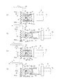
図5は、操作部20が待機位置P0から最大ストロークで押し込まれる際の動作部10の動作を示す。
図5に示す例では、操作部20が待機位置P0から第1位置P1及び第2位置P2を経て、第2位置P2から所定の操作量Δだけさらに押し込まれた第3位置P3まで押し込まれている。
図5(b)は、操作部20が待機位置P0から第1位置P1まで押し込まれた状態を示し、操作部20が第1位置P1まで押し込まれる過程で、図3に詳細に示した通り、切欠き歯33bが第1ラック31に係合し、動作部10が突き出される。
図5(c)は、操作部20が第1位置P1から第2位置P2まで押し込まれた状態を示し、操作部20が第2位置P2まで押し込まれる過程で、図4に詳細に示した通り、切欠き歯33bが第2ラック32に係合し、動作部10が引き込まれる。
図5(d)は、操作部20が第2位置P2から第3位置P3まで押し込まれた状態を示し、操作部20が第3位置P3まで押し込まれる過程で、切欠き歯33bが再び第1ラック31に係合し、動作部10が突き出される。
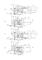
図6は、最大ストロークで押し込まれた操作部20が再び待機位置P0まで操作される際の動作部10の動作を示す。
操作部20は、バネ25によって押し込み方向(図中、矢印Y1方向)とは反対方向(図中、Y2方向)に付勢されており、押し込み操作から解放されるのに応じて、自動的に第3位置P3から待機位置P0に向けて押し戻される。
図6(b)は、操作部20が第3位置P3から第2位置P2まで押し戻された状態を示し、操作部20が第2位置P2まで押し戻される過程で、切欠き歯33bが第1ラック31に係合し、動作部10が引き込まれる。
図6(c)は、操作部20が第2位置P2から第1位置P1まで押し戻された状態を示し、操作部20が第1位置P1まで押し戻される過程で、切欠き歯33bが第2ラック32に係合し、動作部10が突き出される。
図6(d)は、操作部20が第1位置P1から待機位置P0まで押し戻された状態を示し、操作部20が待機位置P0まで押し戻される過程で、切欠き歯33bが再び第1ラック31に係合し、動作部10が引き込まれる。
以上説明したとおり、動作玩具1によれば、操作部20の一方向の操作において、間欠歯車33の切欠き歯33bを第1ラック31及び第2ラック32に交互に係合させて動作部10を反復動作させることができ、動作玩具1の操作性を高めることができる。
また、動作玩具1によれば、操作部20をバネ25によって押し戻しており、操作部20の押し込み方向(図中、矢印Y1方向)の操作のみによって動作部10の反復動作を繰り返すことができ、動作玩具1の操作性をさらに高めることができる。
なお、操作部20の一方向の操作において、間欠歯車33の切欠き歯33bが第1ラック31及び第2ラック32に交互に係合するとは、切欠き歯33bが第1ラック31及び第2ラック32のそれぞれと一回以上係合することを意味する。図5及び図6に示した例では、操作部20の一方向の操作において、切欠き歯33bは、第1ラック31と二回係合し、第2ラック32と一回係合しているが、第1ラック31及び第2ラック32のそれぞれと一回係合するものであってもよいし、第1ラック31及び第2ラック32のそれぞれと複数回係合するものであってもよい。操作部20の一方向の操作における切欠き歯33bと第1ラック31及び第2ラック32のそれぞれとの係合回数、すなわち操作部20の一方向の操作における動作部10の反復動作の回数は、例えば操作部ラック22の歯数、小径歯車部38aと大径歯車部38bとの歯車比、及び大径歯車部38bと操作部側ピニオン33aとの歯車比によって適宜変更することができる。
なお、本実施形態に係る動作玩具は、人形玩具、ロボット玩具、武器玩具等の形象玩具であっても良い。これにより、操作部20の一方向の操作のみによって、例えば、腕であれば連続パンチをさせたり、武器であれば連続突き攻撃をさせたり、噴水であれば連続で噴出させたり等が可能になり、玩具の操作性及び趣向性を高めることができる。
さらに、本発明の動作玩具は、前述した実施形態に限定されるものではなく、適宜な変形、改良が可能である。
例えば、前述した実施形態においては、操作部20を一方向に直線的に押し込む操作をした場合について説明をしてきたが、これに限らない。例えば、操作部20を一方向へ回転操作するものであっても良いし、一方向へ曲線的に傾斜させるように操作するものであっても良い。
また、例えば、前述した実施形態に置いては、操作部20の操作方向は軸線CLと直交する方向である場合について説明をしてきたが、これに限らない。例えば、操作部20の操作方向と軸線CLは平行でも良いし、直交でない方向で交差しても良い。
例えば、前述した実施形態においては、操作部20を一方向に直線的に押し込む操作をした場合について説明をしてきたが、これに限らない。例えば、操作部20を一方向へ回転操作するものであっても良いし、一方向へ曲線的に傾斜させるように操作するものであっても良い。
また、例えば、前述した実施形態に置いては、操作部20の操作方向は軸線CLと直交する方向である場合について説明をしてきたが、これに限らない。例えば、操作部20の操作方向と軸線CLは平行でも良いし、直交でない方向で交差しても良い。
1 動作玩具
10 動作部
11 胴部
12 連結部
20 操作部
22 操作部ラック
25 バネ(付勢部材)
30 伝達部
31 第1ラック
32 第2ラック
33 間欠歯車
33a 操作部側ピニオン
33b 切欠き歯
38 調整歯車
38a 小径歯車部
38b 大径歯車部
40 ケーシング部
CL 軸線
10 動作部
11 胴部
12 連結部
20 操作部
22 操作部ラック
25 バネ(付勢部材)
30 伝達部
31 第1ラック
32 第2ラック
33 間欠歯車
33a 操作部側ピニオン
33b 切欠き歯
38 調整歯車
38a 小径歯車部
38b 大径歯車部
40 ケーシング部
CL 軸線
Claims (6)
- 反復動作可能な動作部と、
前記動作部を動作させるための操作部と、
前記操作部の操作を反復動作として前記動作部に伝達する伝達部と、
を備え、
前記伝達部は、
互いに歯面を対向させて配置された第1ラック及び第2ラックと、
前記第1ラック及び前記第2ラックの間に配置されており、前記操作部の操作に応じて回動され、回動に応じて前記第1ラック及び前記第2ラックのうち一方のラックと選択的に係合する切欠き歯が円周上の一部に形成された間欠歯車と、
を有し、
前記操作部が一方向に操作された際に、前記切欠き歯が前記第1ラック及び前記第2ラックに交互に係合する動作玩具。 - 請求項1記載の動作玩具であって、
前記操作部は、操作部の操作方向に沿った歯車を有し、
前記間欠歯車は、前記操作部の操作が入力される操作部側歯車を有する動作玩具。 - 請求項1乃至2に記載の動作玩具であって、
前記操作部の操作される方向は、前記反復動作の方向と異なる動作玩具。 - 請求項1乃至3に記載の動作玩具であって、
前記操作部の操作される方向は、直線方向である動作玩具。 - 請求項1乃至4に記載の動作玩具であって、
前記操作歯車と前記操作部側歯車との間に調整歯車を有する動作玩具。 - 請求項1乃至5に記載の動作玩具であって、
前記操作部の操作方向とは反対方向に前記操作部を付勢する付勢部材をさらに備える動作玩具。
Applications Claiming Priority (2)
| Application Number | Priority Date | Filing Date | Title |
|---|---|---|---|
| JP2016-130499 | 2016-06-30 | ||
| JP2016130499A JP7002187B2 (ja) | 2016-06-30 | 2016-06-30 | 動作玩具 |
Publications (1)
| Publication Number | Publication Date |
|---|---|
| WO2018003261A1 true WO2018003261A1 (ja) | 2018-01-04 |
Family
ID=60786379
Family Applications (1)
| Application Number | Title | Priority Date | Filing Date |
|---|---|---|---|
| PCT/JP2017/016276 Ceased WO2018003261A1 (ja) | 2016-06-30 | 2017-04-25 | 動作玩具 |
Country Status (2)
| Country | Link |
|---|---|
| JP (1) | JP7002187B2 (ja) |
| WO (1) | WO2018003261A1 (ja) |
Citations (2)
| Publication number | Priority date | Publication date | Assignee | Title |
|---|---|---|---|---|
| JPS5018393U (ja) * | 1973-06-12 | 1975-02-28 | ||
| WO2006133064A2 (en) * | 2005-06-06 | 2006-12-14 | Mattel, Inc. | Pneumatic action figure |
-
2016
- 2016-06-30 JP JP2016130499A patent/JP7002187B2/ja active Active
-
2017
- 2017-04-25 WO PCT/JP2017/016276 patent/WO2018003261A1/ja not_active Ceased
Patent Citations (2)
| Publication number | Priority date | Publication date | Assignee | Title |
|---|---|---|---|---|
| JPS5018393U (ja) * | 1973-06-12 | 1975-02-28 | ||
| WO2006133064A2 (en) * | 2005-06-06 | 2006-12-14 | Mattel, Inc. | Pneumatic action figure |
Also Published As
| Publication number | Publication date |
|---|---|
| JP7002187B2 (ja) | 2022-01-20 |
| JP2018000453A (ja) | 2018-01-11 |
Similar Documents
| Publication | Publication Date | Title |
|---|---|---|
| US7654763B2 (en) | Mechanical pencil | |
| JP5075233B2 (ja) | 電動工具 | |
| CN106801708B (zh) | 双离合器用齿轮促动器 | |
| JP2017515535A5 (ja) | ||
| CN112689723B (zh) | 电动驻车锁致动器受限旋转断开 | |
| JP3886992B2 (ja) | ダブルシリンダーエンジン | |
| CN104776220B (zh) | 自动变速器的驻车机构及自动变速器 | |
| WO2018003261A1 (ja) | 動作玩具 | |
| JP2009299738A (ja) | デュアルクラッチの操作装置 | |
| KR101862471B1 (ko) | 듀얼클러치 액츄에이터 | |
| JP7204869B2 (ja) | 動作玩具 | |
| CN111173365B (zh) | 一种执手 | |
| US1601188A (en) | Reversing gear | |
| JP2014143778A (ja) | 絶縁操作棒 | |
| JP6284658B2 (ja) | 釣り用回転リール | |
| JP4361399B2 (ja) | クラッチ | |
| JP6200048B2 (ja) | 釣り用回転リール | |
| JP5699276B2 (ja) | 電動工具 | |
| CN101922538A (zh) | 一种齿轮式自动换向器 | |
| KR20230081437A (ko) | 랙 앤 피니언 구조를 갖는 차량용 파킹 장치 및 이를 포함하는 차량용 변속기 | |
| CN103707274B (zh) | 电动工具推杆组件 | |
| JP6335549B2 (ja) | クラッチユニット、および、モータ | |
| JP6275329B2 (ja) | 動力伝達装置 | |
| JP2010228037A (ja) | 駆動力解放装置 | |
| JP4870196B2 (ja) | フライホイール |
Legal Events
| Date | Code | Title | Description |
|---|---|---|---|
| 121 | Ep: the epo has been informed by wipo that ep was designated in this application |
Ref document number: 17819628 Country of ref document: EP Kind code of ref document: A1 |
|
| NENP | Non-entry into the national phase |
Ref country code: DE |
|
| 122 | Ep: pct application non-entry in european phase |
Ref document number: 17819628 Country of ref document: EP Kind code of ref document: A1 |