WO2018003102A1 - 生産プログラム最適化システム及び生産管理システム - Google Patents
生産プログラム最適化システム及び生産管理システム Download PDFInfo
- Publication number
- WO2018003102A1 WO2018003102A1 PCT/JP2016/069551 JP2016069551W WO2018003102A1 WO 2018003102 A1 WO2018003102 A1 WO 2018003102A1 JP 2016069551 W JP2016069551 W JP 2016069551W WO 2018003102 A1 WO2018003102 A1 WO 2018003102A1
- Authority
- WO
- WIPO (PCT)
- Prior art keywords
- load factor
- motor
- production
- optimization
- production program
- Prior art date
- Legal status (The legal status is an assumption and is not a legal conclusion. Google has not performed a legal analysis and makes no representation as to the accuracy of the status listed.)
- Ceased
Links
Images



Classifications
-
- G—PHYSICS
- G05—CONTROLLING; REGULATING
- G05B—CONTROL OR REGULATING SYSTEMS IN GENERAL; FUNCTIONAL ELEMENTS OF SUCH SYSTEMS; MONITORING OR TESTING ARRANGEMENTS FOR SUCH SYSTEMS OR ELEMENTS
- G05B19/00—Program-control systems
- G05B19/02—Program-control systems electric
- G05B19/418—Total factory control, i.e. centrally controlling a plurality of machines, e.g. direct or distributed numerical control [DNC], flexible manufacturing systems [FMS], integrated manufacturing systems [IMS] or computer integrated manufacturing [CIM]
-
- H—ELECTRICITY
- H05—ELECTRIC TECHNIQUES NOT OTHERWISE PROVIDED FOR
- H05K—PRINTED CIRCUITS; CASINGS OR CONSTRUCTIONAL DETAILS OF ELECTRIC APPARATUS; MANUFACTURE OF ASSEMBLAGES OF ELECTRICAL COMPONENTS
- H05K13/00—Apparatus or processes specially adapted for manufacturing or adjusting assemblages of electric components
- H05K13/02—Feeding of components
-
- H—ELECTRICITY
- H05—ELECTRIC TECHNIQUES NOT OTHERWISE PROVIDED FOR
- H05K—PRINTED CIRCUITS; CASINGS OR CONSTRUCTIONAL DETAILS OF ELECTRIC APPARATUS; MANUFACTURE OF ASSEMBLAGES OF ELECTRICAL COMPONENTS
- H05K13/00—Apparatus or processes specially adapted for manufacturing or adjusting assemblages of electric components
- H05K13/04—Mounting of components, e.g. of leadless components
-
- Y—GENERAL TAGGING OF NEW TECHNOLOGICAL DEVELOPMENTS; GENERAL TAGGING OF CROSS-SECTIONAL TECHNOLOGIES SPANNING OVER SEVERAL SECTIONS OF THE IPC; TECHNICAL SUBJECTS COVERED BY FORMER USPC CROSS-REFERENCE ART COLLECTIONS [XRACs] AND DIGESTS
- Y02—TECHNOLOGIES OR APPLICATIONS FOR MITIGATION OR ADAPTATION AGAINST CLIMATE CHANGE
- Y02P—CLIMATE CHANGE MITIGATION TECHNOLOGIES IN THE PRODUCTION OR PROCESSING OF GOODS
- Y02P90/00—Enabling technologies with a potential contribution to greenhouse gas [GHG] emissions mitigation
- Y02P90/02—Total factory control, e.g. smart factories, flexible manufacturing systems [FMS] or integrated manufacturing systems [IMS]
Definitions
- the present invention relates to a production program optimization system and a production management system for optimizing a production program for causing a component mounting machine to execute a production operation.
- Patent Document 1 Japanese Patent Laid-Open No. 2002-171097
- Patent Document 2 Japanese Patent Laid-Open No. 2008-218970
- Patent Document 3 Japanese Patent Laid-Open No. 2004-79962
- the mounting order of the components to be mounted on the circuit board is optimized, the arrangement of the feeders to be mounted on the component mounting machine is optimized, and the moving distance and moving time of the mounting head are minimized. Therefore, the production program is optimized so as to obtain the highest production efficiency.
- the motor that is the driving source of the robot that moves the mounting head of the component mounting machine is a motor with sufficient performance so that the robot can be driven normally with an optimized production program.
- a motor with sufficient performance is a large motor and expensive, it cannot meet the demands for cost reduction and space saving of a motor mounted on a component mounting machine.
- a motor with insufficient performance is used, the frequency of overloading the motor during production increases, and the frequency of the motor being stopped due to overload increases, resulting in decreased production efficiency. The problem occurs.
- the problem to be solved by the present invention is to optimize a production program so that even if a motor mounted on a component mounting machine is downsized (small and low price), the motor does not stop due to an overload. It is possible to realize downsizing of the motor with almost no reduction in production efficiency.
- the present invention provides an optimization means for optimizing a production program for causing a component mounting machine that picks up a component supplied by a feeder with a mounting head and mounts the component on a circuit board,
- a load factor calculating unit that calculates a load factor of a motor that moves the mounting head under the conditions optimized by the optimization unit before the start of production; and a load factor of the motor calculated by the load factor calculating unit before the start of production.
- Correction means for correcting the production program optimized by the optimization means based on the optimization means, the optimization means giving priority to increasing production efficiency without first considering the load factor of the motor
- the production program is optimized, and the correction unit optimizes the load when the load factor of the motor calculated by the load factor calculation unit is predicted to exceed a predetermined allowable maximum load factor. It is characterized in that modifying the production program optimized by the step so that the load rate of the motor does not exceed the maximum allowable load factor.
- the optimizing means optimizes the production program by giving priority to increasing the production efficiency without first considering the motor load factor, and the motor load factor calculated by the load factor calculating means is predetermined.
- the production program optimized by the optimization means when it is predicted that the maximum allowable load factor of the motor will be exceeded is modified so that the load factor of the motor does not exceed the allowable maximum load factor. Even if a motor is downsized (downsizing and cost reduction), the production program is optimized so that high performance can be secured by effectively using the performance of the motor as long as the motor does not stop due to overload. Therefore, motor downsizing can be realized with almost no reduction in production efficiency.
- the correction unit changes the condition by the optimization unit and performs optimization processing again.
- the process of recalculating the load factor of the motor by the load factor calculating means may be repeated to correct the production program so that the load factor of the motor does not exceed the allowable maximum load factor.
- the correction unit detects a mounting sequence (part mounting order or the like), and a movement path of the mounting head.
- the optimization process may be performed again by the optimization means by changing at least one of the motor operation parameters (speed, acceleration, etc.).
- the motor load factor calculated by the load factor calculating means when the motor load factor calculated by the load factor calculating means is predicted to exceed the allowable maximum load factor, the motor is stopped during a period in which the motor load factor exceeds the allowable maximum load factor.
- the production time (optimization time) specified by the production program may be corrected so that the production time is extended by the stop time. In this way, the production time specified by the optimized production program can be made to coincide with the actual operation time of the component mounting machine, and the time lag between the two can be eliminated.
- a plurality of feeders are exchangeably mounted on a component mounting machine, and optimized feeder layout information is included in the production program.
- the total current consumption value of the feeder increases or decreases depending on the feeder arrangement, but when the total current consumption value of the feeder exceeds the maximum allowable current consumption value of the power supply, the power supply breaker is activated and the feeder component supply operation is performed. Stop and production stops.
- the equipment cost increases.
- the present invention includes consumption current value calculation means for calculating a total consumption current value of the feeder with the feeder arrangement optimized by the optimization means before the start of production, and the correction means calculates the consumption current value.
- the feeder current optimized by the optimization means is the maximum allowable current consumption of the feeder. You may make it correct so that it may not exceed an electric current value. In this way, it is possible to prevent the total current consumption value of the feeder mounted on the component mounting machine from exceeding the maximum allowable current consumption value without changing to a power supply with a large allowable maximum current consumption value. It is possible to prevent the operation from stopping due to overcurrent, and to avoid an increase in equipment cost.
- the load factor reducing means for reducing the load factor of the motor may be provided. In this way, the production management system can also prevent the motor load factor from exceeding the allowable maximum load factor during production.
- the production program optimization system predicts that the load factor of the motor calculated by the load factor calculation means exceeds the warning value when the production program is optimized by the optimization means before the start of production
- the production program optimized by the optimization means is modified so that the motor load factor does not exceed the warning value, and the production time (optimization time) specified by the production program by the extension of the operation time of the motor due to the modification. ) May be extended.
- the production time specified in the optimized production program matches the actual operation time of the component mounting machine. Can be made.
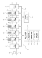
- FIG. 1 is a diagram showing a configuration example of a component mounting line in one embodiment of the present invention.
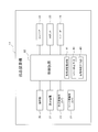
- FIG. 2 is a block diagram showing the configuration of the control system of the component mounting machine.
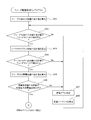
- FIG. 3 is a flowchart showing the processing flow of the first half of the production program optimization program.
- FIG. 4 is a flowchart showing the flow of processing in the latter half of the production program optimization program.
- FIG. 5 is a flowchart showing the processing flow of the first half of the feeder arrangement optimization program.
- FIG. 6 is a flowchart showing the flow of processing in the latter half of the feeder arrangement optimization program.
- a plurality of component mounting machines 14 for mounting components on the circuit board 11 and mounting related machines for performing work related to component mounting are arranged in the transport path 12 for transporting the circuit board 11.
- the mounting-related machine is, for example, a solder printer 13, a reflow apparatus 15, an inspection apparatus, an adhesive application apparatus, or the like.
- a plurality of feeders 16 for supplying components are mounted on a feeder set base (not shown) of each component mounting machine 14 in a replaceable manner.
- One or a plurality of suction nozzles (not shown) for sucking the components supplied by the respective feeders 16 and mounting them on the circuit board 11 are held in the mounting head 17 of each component mounting machine 14 in a replaceable manner. Yes.
- each component mounting machine 14 has an operation unit 20 such as a keyboard, a touch panel, and a mouse, a display device 21 such as a liquid crystal display and a CRT, and a component adsorbed by an adsorption nozzle.
- a component imaging camera 22 for recognizing an image of a suction posture or a displacement amount of the suction position, a substrate imaging camera 23 for imaging a reference mark (not shown) of the circuit board 11, and a conveyor 24 for conveying the circuit board 11.
- a robot 25 that moves the mounting head 17 in the XY directions (horizontal directions).
- the robot 25 includes an X-axis motor (not shown) that drives the mounting head 17 in the X direction, a Y-axis motor (not shown) that drives the mounting head 17 in the Y direction, and the like.
- a plurality of motors are provided.
- a plurality of component mounting machines 14 constituting the component mounting line 10 and mounting related machines such as the solder printer 13 are connected to each other via a network 28 and a production management computer 27 that manages the production of the component mounting line 10. Further, an optimization processing computer 31 for optimizing a production program for causing each component mounting machine 14 to execute a production operation is connected to the network 28, and the production program optimized by the optimization processing computer 31 is connected to the network 28. Is transmitted to each component mounting machine 14 via the network 28.
- the control device 32 of each component mounting machine 14 operates the robot 25 or the like according to the production program received from the optimization processing computer 31 and moves the mounting head 17 along the path of the component suction position ⁇ the component imaging position ⁇ the component mounting position. Then, the component supplied by the feeder 16 is picked up by the suction nozzle of the mounting head 17, the component is imaged by the component imaging camera 22, the amount of displacement of the component suction position is recognized, and the component is detected by the circuit board 11. A predetermined number of components are mounted on the circuit board 11 by repeating the operation of mounting on the circuit board 11.
- the optimization processing computer 31 is an optimization that optimizes the production program by executing each of the optimization processing programs shown in FIGS. 3 to 6 described later in the production program optimization step before the start of production.
- Load factor calculation that functions as the means 35 and further calculates the load factor of the motor that moves the mounting head 17 under the conditions optimized by the optimization means 35 before the start of production based on the current value or temperature flowing through the motor.
- correction means 37 for correcting the production program optimized by the optimization means 35 based on the motor load factor calculated by the load factor calculation means 36 before the start of production.
- the optimization unit 35 first optimizes the production program by giving priority to increasing the production efficiency without considering the load factor of the motor, and the correction unit 37 sets the motor calculated by the load factor calculation unit 36.
- the load factor is predicted to exceed a predetermined allowable maximum load factor (the load factor at which the motor stops due to an error)
- the motor load factor of the production program optimized by the optimization means 35 does not exceed the allowable maximum load factor. Modify as follows.
- the correction means 37 changes, for example, at least one of a mounting sequence (part mounting order, etc.), a movement path of the mounting head 17, and motor operating parameters (speed, acceleration, etc.)
- the production program is modified so that the load factor of the motor does not exceed the allowable maximum load factor by repeating the process of re-optimizing by the optimizing unit 35 and recalculating the load factor of the motor by the load factor calculating unit 36. .
- the correcting unit 37 performs the motor in a period in which the motor load factor exceeds the allowable maximum load factor.
- the production time (optimization time) designated by the production program may be corrected so that the production time is extended by the stop time. In this way, the production time specified by the optimized production program can be made to coincide with the actual operation time of the component mounting machine 14, and the time lag between the two can be eliminated.
- the production program correction based on the motor load factor described above is performed so that the load factors of all the motors that are the drive source of the robot 25 do not exceed the allowable maximum load factor.
- a plurality of feeders 16 are exchangeably mounted on the component mounting machine 14, and the information on the arrangement of the optimized feeders 16 is included in the production program.
- the total current consumption value of the feeder 16 increases or decreases depending on the arrangement of the feeder 16, but when the total current consumption value of the feeder 16 exceeds the allowable maximum current consumption value (maximum current value that can be supplied) of the power supply, the feeder 16 The breaker of the power source that supplies current is activated, and the parts supply operation of the feeder 16 is stopped, and the production is stopped.
- the equipment cost increases.
- the optimization processing computer 31 calculates the total current consumption value of the feeder 16 by the arrangement of the feeder 16 optimized by the optimization means 35 in the production program optimization process before the start of production. It also functions as the consumption current value calculation means 38, and the correction means 37 optimizes when it is predicted that the total consumption current value of the feeder 16 calculated by the consumption current value calculation means 38 exceeds the allowable maximum consumption current value of the power source.
- the arrangement of the feeder 16 optimized by the means 35 is modified so that the total current consumption value of the feeder 16 does not exceed the allowable maximum current consumption value of the power source.
- the control device 32 of the component mounting machine 14 functions as a load factor monitoring means 41 that monitors the load factor of the motor during production. When the load factor of the motor exceeds the allowable maximum load factor during production, the control device 32 gives an error to the motor. It functions as the error stop means 42 for stopping, and also functions as the load factor lowering means 43 for reducing the load factor of the motor when the load factor of the motor exceeds a warning value lower than the allowable maximum load factor during production. In this way, the component mounting machine 14 can also prevent the motor load factor from exceeding the allowable maximum load factor during production.
- the optimization computer 31 predicts that the load factor of the motor calculated by the load factor calculator 36 exceeds the warning value at the time when the optimization program 35 optimizes the production program before starting production.
- the production program optimized by the optimization means 35 is modified so that the load factor of the motor does not exceed the warning value, and the production time specified by the production program corresponding to the extension of the motor operating time due to the modification (optimization) (Time) may be extended.
- the production time specified by the optimized production program is the actual operation time of the component mounting machine 14. Can be matched.
- the production program optimization program of FIGS. 3 and 4 is executed by the optimization processing computer 31 in the production program optimization process before the start of production.
- this program is started, first, in step 101, various data for the production program are read, and in the next step 102, the suction nozzle of the mounting sequence is determined.
- step 103 where the mounting sequence is distributed to each component mounting machine 14, and in the next step 104, the component mounting order is calculated for each component mounting machine 14, and then the process proceeds to step 105, where the component mounting order is based.
- step 105 where the component mounting order is based.
- the arrangement of the feeders 16 is optimized (the optimum loading order of the feeders 16 is calculated).
- step 106 it is determined whether or not all the feeders 16 can be mounted on the feeder set base of the component mounting machine 14 with the optimized arrangement of the feeders 16.
- the mounting sequence to be distributed to the mounting machine 14 is changed, and the processing of steps 103 to 105 is executed again to optimize the arrangement of the feeder 16 again.
- step 106 Thereafter, if it is determined in step 106 that all the feeders 16 can be mounted with the optimized arrangement of the feeders 16, the process proceeds to step 107 in FIG. 4 to calculate the load factor of the motor.
- step 108 It is determined whether or not the load factor of the motor is 100% or less, which is the allowable maximum load factor. As a result, if it is determined that the load factor of the motor is 100% or less, it is determined that the optimization of the production program is completed, the process proceeds to step 109, the optimized production program is saved, and this program is terminated. .
- step 110 determines whether or not to optimize the production program again.
- whether or not to re-optimize the production program may be manually set by the user, or it is determined that the optimization is automatically re-optimized until the optimization process is repeated a predetermined number of times. When the number of optimization processes exceeds a predetermined number, it may be determined not to re-optimize.
- step 110 If it is determined in step 110 that the production program is to be re-optimized, the process proceeds to step 111, where the mounting sequence in which the load factor of the motor exceeds 100% is replaced with another mounting sequence, and the moving distance of the mounting head 17 is changed. Returning to step 107, the motor load factor is recalculated. In the next step 108, it is determined whether or not the motor load factor is 100% or less, which is the allowable maximum load factor.
- step 110 determines whether the optimization is performed again. If it is determined in step 110 that the optimization is not performed again, the process proceeds to step 112, and the stop time when the motor load factor exceeds 100% is added to the production time (optimization time) specified by the production program. In step 109, the optimized production program is stored, and the program is terminated.
- the feeder arrangement optimization program shown in FIGS. 5 and 6 is optimal when the user selects the optimization of the arrangement of the feeder 16 in consideration of the total current consumption value of the feeder 16 in the production program optimization process before the start of production. It is executed by the computer 31 for processing.
- this program is started, first, in step 201, the total occupied width of the main body of the feeder 16 mounted on the feeder set base of the component mounting machine 14 is calculated, and in the next step 202, the main body of the feeder 16 is calculated. It is determined whether or not the total occupied width is within the width of the feeder set base.
- step 207 it is determined that the feeder 16 cannot be mounted on the feeder set base, and the process proceeds to step 208. Then, the mounting sequence is changed, and the processes in steps 201 and 202 are performed again.
- step 202 determines whether the total occupied width of the main body of the feeder 16 is within the width of the feeder set base. If it is determined in step 202 that the total occupied width of the main body of the feeder 16 is within the width of the feeder set base, the process proceeds to step 203 and the feeder 16 mounted on the feeder set base of the component mounting machine 14 is reached. The total value of the occupied widths of the reel holders is calculated, and in the next step 204, it is determined whether or not the total value of the occupied widths of the reel holders of the feeder 16 is within the width of the feeder set base. As a result, if it is determined that the total value of the occupied widths of the reel holders of the feeder 16 is larger than the width of the feeder set table, the process proceeds to step 207, where it is determined that the feeder 16 cannot be mounted on the feeder set table. Then, the mounting sequence is changed, and the processing of steps 201 to 204 is performed again.
- step 204 if it is determined in step 204 that the total value of the occupied widths of the reel holders of the feeder 16 is within the width of the feeder set base, the process proceeds to step 205 and the feeder mounted on the feeder set base of the component mounting machine 14 is reached. 16 is calculated, and in the next step 206, it is determined whether or not the total current consumption value of the feeder 16 is within the allowable maximum current consumption value (maximum supplyable current value) of the power source. judge. As a result, if it is determined that the total current consumption value of the feeder 16 exceeds the allowable maximum current consumption value, the process proceeds to step 207, where it is determined that the feeder 16 cannot be mounted on the feeder set base.
- allowable maximum current consumption value maximum supplyable current value
- step 206 the mounting sequence is changed, and the processes in steps 201 to 206 are performed again. Even if the change of the mounting sequence is repeated a predetermined number of times, if it is determined in step 206 that the total current consumption value of the feeder 16 exceeds the allowable maximum current consumption value, it is finally determined that mounting is impossible. This program may be determined and terminated.
- step 206 if it is determined in step 206 above that the total current consumption value of the feeder 16 is within the allowable maximum current consumption value, the process proceeds to step 209 in FIG.
- the feeder 16 is arranged so as to be shorter. After this, the process proceeds to step 210, where it is determined whether or not the main body of the adjacent feeder 16 can be mounted on the feeder set base at the current mounting pitch. If it is widened, it is determined whether or not the main body of the feeder 16 can be mounted. As a result, if it is determined that the main body of the feeder 16 cannot be mounted even if the mounting pitch is widened, the process proceeds to step 218, where it is finally determined that mounting cannot be performed, and this program ends.
- step 216 determines whether the main body of the feeder 16 can be mounted if the mounting pitch is widened. If it is determined in step 210 that the main body of the adjacent feeder 16 can be mounted on the feeder set base at the current mounting pitch, the process proceeds to step 211.
- step 211 it is determined whether or not the adjacent reel holders can be mounted at the current mounting pitch. If it is determined that the reel holders cannot be mounted, the process proceeds to step 218. Exit the program.
- step 211 determines whether or not there is a feeder 16 that has not been checked for mounting. If it is determined that it remains, the processing from step 210 onward is repeated. Thereafter, when all the feeders 16 have been checked, the process proceeds to step 215, where it is determined that mounting is possible, and this program ends.
- the optimization program 35 optimizes the production program by first giving priority to increasing the production efficiency without considering the load factor of the motor, and the load factor calculation device 36 calculates it.
- the production program optimized by the optimization means 35 is modified so that the motor load factor does not exceed the allowable maximum load factor. Even if the motor mounted on the component mounting machine 14 is downsized (small size and low price), high performance can be secured by effectively using the performance of the motor within a range in which the motor does not stop due to overload.
- the production program can be optimized, and downsizing of the motor can be realized without substantially reducing the production efficiency.
- the motor when it is predicted that the load factor of the motor calculated by the load factor calculation means 36 exceeds the allowable maximum load factor, the motor is used during a period when the load factor of the motor exceeds the allowable maximum load factor.
- the production time (optimization time) specified in the production program is modified so that the production time is extended by the stop time and the production time (optimization time) specified by the optimized production program is used.
- the operation time can be made to coincide with each other, and the time lag between the two can be eliminated.
- the optimization unit 35 optimizes the feeder 16. Since the arrangement is corrected so that the total current consumption value of the feeder 16 does not exceed the allowable maximum current consumption value, it is mounted on the component mounting machine 14 without changing to a power supply having a large allowable maximum current consumption value. Thus, it is possible to prevent the total current consumption value of the feeder 16 from exceeding the allowable maximum current consumption value, to prevent the component supply operation of the feeder 16 from being stopped due to overcurrent, and to avoid an increase in equipment cost.
- the production management computer 27 executes the optimization process of the production program executed by the configuration processing component 31 or the optimization processing computer 31. Needless to say, various modifications can be made without departing from the spirit of the invention.
Landscapes
- Engineering & Computer Science (AREA)
- Manufacturing & Machinery (AREA)
- Microelectronics & Electronic Packaging (AREA)
- General Engineering & Computer Science (AREA)
- Quality & Reliability (AREA)
- Physics & Mathematics (AREA)
- General Physics & Mathematics (AREA)
- Automation & Control Theory (AREA)
- Supply And Installment Of Electrical Components (AREA)
- General Factory Administration (AREA)
Abstract
生産開始前の生産プログラム最適化工程で、最適化手段(35)は、最初はモータの負荷率を考慮せずに生産効率を高めることを優先して生産プログラムを最適化し、修正手段(37)は、負荷率算出手段(36)で算出したモータの負荷率が所定の許容最大負荷率を超えると予想したときに、最適化手段で最適化した生産プログラムをモータの負荷率が前記許容最大負荷率を超えないように修正する。生産プログラムを修正する際に、例えば、装着シーケンス、装着ヘッド(17)の移動経路、モータの動作パラメータの少なくとも1つを変更して、最適化手段で最適化処理をやり直して負荷率算出手段でモータの負荷率を算出し直すという処理を繰り返してモータの負荷率が前記許容最大負荷率を超えないように生産プログラムを修正する。
Description
本発明は、部品装着機に生産動作を実行させる生産プログラムを最適化する生産プログラム最適化システム及び生産管理システムに関する発明である。
部品装着機の生産効率を高めるために、部品装着機に生産動作を実行させる生産プログラムを最適化することが行われている。従来の一般的な最適化手法は、例えば、特許文献1(特開2002-171097号公報)、特許文献2(特開2008-218970号公報)、特許文献3(特開2004-79962号公報)に記載されているように、回路基板に装着する部品の装着順序を最適化したり、部品装着機に搭載するフィーダの配置を最適化して、装着ヘッドの移動距離や移動時間を最短にするなどして、最高の生産効率が得られるように生産プログラムを最適化するようにしている。
部品装着機の装着ヘッドを移動させるロボットの駆動源となるモータは、最適化した生産プログラムでロボットを正常に駆動できるように、性能に余裕のあるモータを採用するようにしている。しかし、性能に余裕のあるモータは、大型のモータで、高価であるため、部品装着機に搭載するモータの低コスト化や省スペース化の要求を満たすことができない。かといって、性能に余裕のないモータを採用すると、生産中にモータの負荷が過負荷になる頻度が増加して、当該モータが過負荷によりエラー停止する頻度が増加して生産効率が低下するという問題が発生する。
そこで、本発明が解決しようとする課題は、部品装着機に搭載するモータをダウンサイジング(小型・低価格化)しても、そのモータが過負荷によりエラー停止しないように生産プログラムを最適化することができ、生産効率をほとんど低下させることなくモータのダウンサイジングを実現できるようにすることである。
上記課題を解決するために、本発明は、フィーダで供給される部品を装着ヘッドでピックアップして回路基板に装着する部品装着機に生産動作を実行させる生産プログラムを最適化する最適化手段と、生産開始前に前記最適化手段で最適化した条件で前記装着ヘッドを移動させるモータの負荷率を算出する負荷率算出手段と、生産開始前に前記負荷率算出手段で算出した前記モータの負荷率に基づいて前記最適化手段で最適化した前記生産プログラムを修正する修正手段とを備え、前記最適化手段は、最初は前記モータの負荷率を考慮せずに生産効率を高めることを優先して前記生産プログラムを最適化し、前記修正手段は、前記負荷率算出手段で算出した前記モータの負荷率が所定の許容最大負荷率を超えると予想したときに前記最適化手段で最適化した前記生産プログラムを前記モータの負荷率が前記許容最大負荷率を超えないように修正することを特徴とするものである。
本発明では、前記最適化手段により、最初はモータの負荷率を考慮せずに生産効率を高めることを優先して生産プログラムを最適化し、前記負荷率算出手段で算出したモータの負荷率が所定の許容最大負荷率を超えると予想したときに前記最適化手段で最適化した生産プログラムをモータの負荷率が許容最大負荷率を超えないように修正するようにしたので、部品装着機に搭載するモータをダウンサイジング(小型・低価格化)しても、そのモータが過負荷によりエラー停止しない範囲内でそのモータの性能を有効に利用して高い生産効率を確保できるように生産プログラムを最適化することができ、生産効率をほとんど低下させることなくモータのダウンサイジングを実現できる。
この場合、前記修正手段は、前記負荷率算出手段で算出したモータの負荷率が前記許容最大負荷率を超えると予想したときに、前記最適化手段で条件を変更して最適化処理をやり直して前記負荷率算出手段で前記モータの負荷率を算出し直すという処理を繰り返して前記モータの負荷率が前記許容最大負荷率を超えないように生産プログラムを修正するようにすれば良い。
具体的には、前記修正手段は、前記負荷率算出手段で算出したモータの負荷率が前記許容最大負荷率を超えると予想したときに、装着シーケンス(部品装着順序等)、装着ヘッドの移動経路、モータの動作パラメータ(速度、加速度等)の少なくとも1つを変更して前記最適化手段で最適化処理をやり直すようにすれば良い。
また、本発明は、前記負荷率算出手段で算出したモータの負荷率が前記許容最大負荷率を超えると予想したときに、モータの負荷率が前記許容最大負荷率を超える期間に当該モータを停止させると共にその停止時間分だけ生産時間を延ばすように生産プログラムで指定する生産時間(最適化時間)を修正するようにしても良い。このようにすれば、最適化した生産プログラムで指定する生産時間を部品装着機の実際の動作時間と一致させることができ、両者の時間のずれを無くすことができる。
一般に、部品装着機には、複数のフィーダが交換可能に搭載され、生産プログラムには、最適化したフィーダの配置の情報も含まれる。この場合、フィーダの配置によってフィーダの合計消費電流値が増減するが、フィーダの合計消費電流値が電源の許容最大消費電流値を超えると、電源のブレーカーが作動して、フィーダの部品供給動作が停止して生産が停止してしまう。この対策として、許容最大消費電流値の大きな電源に変更すると、設備コストが増加してしまう。
そこで、本発明は、生産開始前に前記最適化手段で最適化したフィーダの配置で当該フィーダの合計消費電流値を算出する消費電流値算出手段を備え、前記修正手段は、前記消費電流値算出手段で算出したフィーダの合計消費電流値が電源の許容最大消費電流値を超えると予想したときに、前記最適化手段で最適化したフィーダの配置をそのフィーダの合計消費電流値が前記許容最大消費電流値を超えないように修正するようにしても良い。このようにすれば、許容最大消費電流値の大きな電源に変更しなくても、部品装着機に搭載したフィーダの合計消費電流値が許容最大消費電流値を超えることを防止でき、フィーダの部品供給動作が過電流により停止することを防止できると共に、設備コストの増加も回避することができる。
以上のように構成した生産プログラム最適化システムで最適化した生産プログラムに従って部品装着機を稼働させて生産状況を管理する生産管理システムにおいては、生産中にモータの負荷率を監視する負荷率監視手段と、生産中にモータの負荷率が許容最大負荷率を超えたときに当該モータをエラー停止させるエラー停止手段と、生産中にモータの負荷率が前記許容最大負荷率よりも低い警戒値を超えたときに当該モータの負荷率を低下させる負荷率低下手段とを備えた構成とすると良い。このようにすれば、生産中にモータの負荷率が許容最大負荷率を超えることを生産管理システムでも防止できる。
この場合、生産プログラム最適化システムは、生産開始前に最適化手段で生産プログラムを最適化する時点で、負荷率算出手段で算出したモータの負荷率が警戒値を超えると予想したときに、前記最適化手段で最適化した生産プログラムをモータの負荷率が前記警戒値を超えないように修正すると共に、その修正によるモータの動作時間の延び分だけ前記生産プログラムで指定する生産時間(最適化時間)を延ばすようにしても良い。このようにすれば、生産中にモータの負荷率が許容最大負荷率を超えることをより確実に防止できると共に、最適化した生産プログラムで指定する生産時間を部品装着機の実際の動作時間と一致させることができる。
以下、本発明を実施するための形態を具体化した一実施例を説明する。
まず、図1に基づいて部品装着ライン10の構成を説明する。
まず、図1に基づいて部品装着ライン10の構成を説明する。
回路基板11を搬送する搬送経路12には、回路基板11に部品を装着する複数の部品装着機14と、部品装着に関連する作業を行う装着関連機が配列されている。ここで、装着関連機は、例えば、半田印刷機13、リフロー装置15、検査装置、接着剤塗布装置等である。
各部品装着機14のフィーダセット台(図示せず)には、それぞれ部品を供給する複数のフィーダ16が交換可能に搭載されている。各部品装着機14の装着ヘッド17には、各フィーダ16で供給される部品を吸着して回路基板11に装着する1本又は複数本の吸着ノズル(図示せず)が交換可能に保持されている。
図2に示すように、各部品装着機14には、キーボード、タッチパネル、マウス等の操作部20と、液晶ディスプレイ、CRT等の表示装置21と、吸着ノズルに吸着した部品を撮像して部品の吸着姿勢や吸着位置のずれ量等を画像認識する部品撮像用カメラ22と、回路基板11の基準マーク(図示せず)等を撮像する基板撮像用カメラ23と、回路基板11を搬送するコンベア24と、装着ヘッド17をXY方向(水平方向)に移動させるロボット25等が設けられている。尚、図示はしないが、ロボット25には、装着ヘッド17をX方向に駆動するX軸モータ(図示せず)と、装着ヘッド17をY方向に駆動するY軸モータ(図示せず)等の複数のモータが設けられている。
部品装着ライン10を構成する複数の部品装着機14と半田印刷機13等の装着関連機は、部品装着ライン10の生産を管理する生産管理コンピュータ27とネットワーク28を介して相互に通信可能に接続され、更に、このネットワーク28には、各部品装着機14に生産動作を実行させる生産プログラムを最適化する最適化処理用コンピュータ31が接続され、この最適化処理用コンピュータ31で最適化した生産プログラムがネットワーク28を介して各部品装着機14に送信される。
各部品装着機14の制御装置32は、最適化処理用コンピュータ31から受信した生産プログラムに従ってロボット25等を動作させて、装着ヘッド17を部品吸着位置→部品撮像位置→部品装着位置の経路で移動させて、フィーダ16で供給される部品を装着ヘッド17の吸着ノズルでピックアップして当該部品を部品撮像用カメラ22で撮像して部品吸着位置のずれ量等を認識して当該部品を回路基板11に装着するという動作を繰り返して、当該回路基板11に所定数の部品を装着する。
一方、最適化処理用コンピュータ31は、生産開始前の生産プログラム最適化工程で、後述する図3乃至図6の最適化処理用の各プログラムを実行することで、生産プログラムを最適化する最適化手段35として機能し、更に、生産開始前に最適化手段35で最適化した条件で装着ヘッド17を移動させるモータの負荷率を当該モータに流れる電流値又は温度等に基づいて算出する負荷率算出手段36として機能すると共に、生産開始前に負荷率算出手段36で算出したモータの負荷率に基づいて最適化手段35で最適化した生産プログラムを修正する修正手段37としても機能する。
この場合、最適化手段35は、最初はモータの負荷率を考慮せずに生産効率を高めることを優先して生産プログラムを最適化し、修正手段37は、負荷率算出手段36で算出したモータの負荷率が所定の許容最大負荷率(モータがエラー停止する負荷率)を超えると予想したときに、最適化手段35で最適化した生産プログラムをモータの負荷率が前記許容最大負荷率を超えないように修正する。
生産プログラムを修正する際に、修正手段37は、例えば、装着シーケンス(部品装着順序等)、装着ヘッド17の移動経路、モータの動作パラメータ(速度、加速度等)の少なくとも1つを変更して、最適化手段35で最適化処理をやり直して負荷率算出手段36でモータの負荷率を算出し直すという処理を繰り返してモータの負荷率が前記許容最大負荷率を超えないように生産プログラムを修正する。
或は、修正手段37は、負荷率算出手段36で算出したモータの負荷率が前記許容最大負荷率を超えると予想したときに、モータの負荷率が前記許容最大負荷率を超える期間に当該モータを停止させると共にその停止時間分だけ生産時間を延ばすように生産プログラムで指定する生産時間(最適化時間)を修正するようにしても良い。このようにすれば、最適化した生産プログラムで指定する生産時間を部品装着機14の実際の動作時間と一致させることができ、両者の時間のずれを無くすことができる。
以上説明したモータの負荷率に基づく生産プログラムの修正は、ロボット25の駆動源となる全てのモータの負荷率が許容最大負荷率を超えないように実施される。
ところで、部品装着機14には、複数のフィーダ16が交換可能に搭載され、生産プログラムには、最適化したフィーダ16の配置の情報も含まれる。この場合、フィーダ16の配置によってフィーダ16の合計消費電流値が増減するが、フィーダ16の合計消費電流値が電源の許容最大消費電流値(供給可能な最大電流値)を超えると、フィーダ16に電流を供給する電源のブレーカーが作動してフィーダ16の部品供給動作が停止して生産が停止してしまう。この対策として、許容最大消費電流値の大きな電源に変更すると、設備コストが増加してしまう。
そこで、本実施例では、最適化処理用コンピュータ31は、生産開始前の生産プログラム最適化工程で、最適化手段35で最適化したフィーダ16の配置で当該フィーダ16の合計消費電流値を算出する消費電流値算出手段38としても機能し、修正手段37は、消費電流値算出手段38で算出したフィーダ16の合計消費電流値が電源の許容最大消費電流値を超えると予想したときに、最適化手段35で最適化したフィーダ16の配置をそのフィーダ16の合計消費電流値が電源の許容最大消費電流値を超えないように修正するようにしている。このようにすれば、許容最大消費電流値の大きな電源に変更しなくても、部品装着機14に搭載したフィーダ16の合計消費電流値が許容最大消費電流値を超えることを防止でき、フィーダ16の部品供給動作が過電流により停止することを防止できると共に、設備コストの増加も回避することができる。尚、フィーダ16の合計消費電流値を考慮したフィーダ16の配置の最適化を行うか否かは、ユーザーが選択できるようにしても良い。
以上のようにして最適化した生産プログラムに従って各部品装着機14を稼働させるため、生産中にモータの負荷率が許容最大負荷率を超えることはほとんどないと思われるが、安全のために、各部品装着機14の制御装置32は、生産中にモータの負荷率を監視する負荷率監視手段41として機能し、生産中にモータの負荷率が許容最大負荷率を超えたときに当該モータをエラー停止させるエラー停止手段42として機能すると共に、生産中にモータの負荷率が許容最大負荷率よりも低い警戒値を超えたときに当該モータの負荷率を低下させる負荷率低下手段43として機能する。このようにすれば、生産中にモータの負荷率が許容最大負荷率を超えることを部品装着機14でも防止できる。
この場合、最適化処理用コンピュータ31は、生産開始前に最適化手段35で生産プログラムを最適化する時点で、負荷率算出手段36で算出したモータの負荷率が警戒値を超えると予想したときに最適化手段35で最適化した生産プログラムをモータの負荷率が前記警戒値を超えないように修正すると共に、その修正によるモータの動作時間の延び分だけ生産プログラムで指定する生産時間(最適化時間)を延ばすようにしても良い。このようにすれば、生産中にモータの負荷率が許容最大負荷率を超えることをより確実に防止できると共に、最適化した生産プログラムで指定する生産時間を部品装着機14の実際の動作時間と一致させることができる。
次に、最適化処理用コンピュータ31が実行する生産プログラム最適化処理の一例を、図3乃至図6を用いて説明する。
[生産プログラム最適化プログラム]
図3及び図4の生産プログラム最適化プログラムは、生産開始前の生産プログラム最適化工程で最適化処理用コンピュータ31によって実行される。本プログラムが起動されると、まず、ステップ101で、生産プログラム用の各種データを読み込み、次のステップ102で、装着シーケンスの吸着ノズルを決定する。
図3及び図4の生産プログラム最適化プログラムは、生産開始前の生産プログラム最適化工程で最適化処理用コンピュータ31によって実行される。本プログラムが起動されると、まず、ステップ101で、生産プログラム用の各種データを読み込み、次のステップ102で、装着シーケンスの吸着ノズルを決定する。
この後、ステップ103に進み、各部品装着機14に装着シーケンスを配分し、次のステップ104で、各部品装着機14毎に部品装着順を算出した後、ステップ105に進み、部品装着順に基づいてフィーダ16の配置を最適化する(フィーダ16の最適な搭載順を算出する)。そして、次のステップ106で、最適化したフィーダ16の配置で、部品装着機14のフィーダセット台に全てのフィーダ16を搭載可能か否かを判定し、搭載できないと判定されれば、各部品装着機14に配分する装着シーケンスを変更して、上記ステップ103~105の処理を再度実行して、フィーダ16の配置の最適化をやり直す。
その後、上記ステップ106で、最適化したフィーダ16の配置で全てのフィーダ16を搭載可能と判定されれば、図4のステップ107へ進み、モータの負荷率を算出し、次のステップ108で、モータの負荷率が許容最大負荷率である100%以下であるか否かを判定する。その結果、モータの負荷率が100%以下であると判定されれば、生産プログラムの最適化完了と判断して、ステップ109に進み、最適化した生産プログラムを保存して、本プログラムを終了する。
一方、上記ステップ108で、モータの負荷率が100%を超えていると判定されれば、ステップ110に進み、生産プログラムを最適化し直すか否かを判定する。ここで、生産プログラムを最適化し直すか否かは、ユーザーが手動設定するようにしても良いし、或は、最適化の処理を所定回数繰り返すまでは、自動的に最適化し直すと判定し、最適化の処理回数が所定回数を超えた時点で、最適化し直さないと判定するようにしても良い。
上記ステップ110で、生産プログラムを最適化し直すと判定されれば、ステップ111に進み、モータの負荷率が100%を超える装着シーケンスを他の装着シーケンスと入れ替えて装着ヘッド17の移動距離を変更して、上記ステップ107に戻り、モータの負荷率を算出し直して、次のステップ108で、モータの負荷率が許容最大負荷率である100%以下であるか否かを判定する。
上述したステップ107→108→110→111の処理を繰り返して、モータの負荷率が100%以下になった時点で、生産プログラムの最適化完了と判断して、ステップ109に進み、最適化した生産プログラムを保存して、本プログラムを終了する。
一方、上記ステップ110で、最適化し直さないと判定されれば、ステップ112に進み、モータの負荷率が100%を超えるときの停止時間を生産プログラムで指定する生産時間(最適化時間)に加算して、ステップ109に進み、最適化した生産プログラムを保存して、本プログラムを終了する。
[フィーダ配置最適化プログラム]
図5及び図6のフィーダ配置最適化プログラムは、生産開始前の生産プログラム最適化工程で、ユーザーがフィーダ16の合計消費電流値を考慮したフィーダ16の配置の最適化を選択した場合に、最適化処理用コンピュータ31によって実行される。本プログラムが起動されると、まず、ステップ201で、部品装着機14のフィーダセット台に搭載するフィーダ16の本体の占有幅の合計値を算出し、次のステップ202で、フィーダ16の本体の占有幅の合計値がフィーダセット台の幅以内であるか否かを判定する。その結果、フィーダ16の本体の占有幅の合計値がフィーダセット台の幅よりも大きいと判定されれば、ステップ207に進み、フィーダ16をフィーダセット台に搭載できないと判定して、ステップ208に進み、装着シーケンスを変更して、上記ステップ201、202の処理をやり直す。
図5及び図6のフィーダ配置最適化プログラムは、生産開始前の生産プログラム最適化工程で、ユーザーがフィーダ16の合計消費電流値を考慮したフィーダ16の配置の最適化を選択した場合に、最適化処理用コンピュータ31によって実行される。本プログラムが起動されると、まず、ステップ201で、部品装着機14のフィーダセット台に搭載するフィーダ16の本体の占有幅の合計値を算出し、次のステップ202で、フィーダ16の本体の占有幅の合計値がフィーダセット台の幅以内であるか否かを判定する。その結果、フィーダ16の本体の占有幅の合計値がフィーダセット台の幅よりも大きいと判定されれば、ステップ207に進み、フィーダ16をフィーダセット台に搭載できないと判定して、ステップ208に進み、装着シーケンスを変更して、上記ステップ201、202の処理をやり直す。
一方、上記ステップ202で、フィーダ16の本体の占有幅の合計値がフィーダセット台の幅以内であると判定されれば、ステップ203に進み、部品装着機14のフィーダセット台に搭載するフィーダ16のリールホルダの占有幅の合計値を算出し、次のステップ204で、フィーダ16のリールホルダの占有幅の合計値がフィーダセット台の幅以内であるか否かを判定する。その結果、フィーダ16のリールホルダの占有幅の合計値がフィーダセット台の幅よりも大きいと判定されれば、ステップ207に進み、フィーダ16をフィーダセット台に搭載できないと判定して、ステップ208に進み、装着シーケンスを変更して、上記ステップ201~204の処理をやり直す。
一方、上記ステップ204で、フィーダ16のリールホルダの占有幅の合計値がフィーダセット台の幅以内であると判定されれば、ステップ205に進み、部品装着機14のフィーダセット台に搭載するフィーダ16の消費電流値の合計値を算出し、次のステップ206で、フィーダ16の消費電流値の合計値が電源の許容最大消費電流値(供給可能な最大電流値)以内であるか否かを判定する。その結果、フィーダ16の消費電流値の合計値が許容最大消費電流値を超えていると判定されれば、ステップ207に進み、フィーダ16をフィーダセット台に搭載できないと判定して、ステップ208に進み、装着シーケンスを変更して、上記ステップ201~206の処理をやり直す。尚、装着シーケンスの変更を所定回数繰り返しても、上記ステップ206で、フィーダ16の消費電流値の合計値が許容最大消費電流値を超えていると判定される場合は、最終的に搭載不可と判定して、本プログラムを終了するようにしても良い。
これに対し、上記ステップ206で、フィーダ16の消費電流値の合計値が許容最大消費電流値以内と判定されれば、図6のステップ209へ進み、部品装着順に従って、装着ヘッド17の移動距離が短くなるようにフィーダ16を配置する。この後、ステップ210に進み、隣り合うフィーダ16の本体を現在の搭載ピッチでフィーダセット台に搭載可能であるか否かを判定し、搭載できないと判定されれば、ステップ216に進み、搭載ピッチを広げればフィーダ16の本体を搭載可能であるか否かを判定する。その結果、搭載ピッチを広げてもフィーダ16の本体を搭載できないと判定されれば、ステップ218に進み、最終的に搭載不可と判定して、本プログラムを終了する。
一方、上記ステップ216で、搭載ピッチを広げればフィーダ16の本体を搭載可能できると判定されれば、ステップ217に進み、搭載ピッチを広げて、ステップ211に進む。また、上記ステップ210で、隣り合うフィーダ16の本体を現在の搭載ピッチでフィーダセット台に搭載可能であると判定された場合も、ステップ211に進む。
このステップ211では、隣り合うリールホルダを現在の搭載ピッチで搭載可能であるか否かを判定し、搭載できないと判定されれば、ステップ218に進み、最終的に搭載不可と判定して、本プログラムを終了する。
一方、上記ステップ211で、隣り合うリールホルダを現在の搭載ピッチで搭載可能であると判定されれば、ステップ214に進み、搭載可能かチェックしていないフィーダ16が残っているか否かを判定し、残っていると判定されれば、上記ステップ210以降の処理を繰り返す。その後、全てのフィーダ16のチェックを終了した時点で、ステップ215に進み、搭載可能と判定して、本プログラムを終了する。
以上説明した本実施例によれば、最適化手段35により、最初はモータの負荷率を考慮せずに生産効率を高めることを優先して生産プログラムを最適化し、負荷率算出手段36で算出したモータの負荷率が所定の許容最大負荷率を超えると予想したときに最適化手段35で最適化した生産プログラムをモータの負荷率が許容最大負荷率を超えないように修正するようにしたので、部品装着機14に搭載するモータをダウンサイジング(小型・低価格化)しても、そのモータが過負荷によりエラー停止しない範囲内でそのモータの性能を有効に利用して高い生産効率を確保できるように生産プログラムを最適化することができ、生産効率をほとんど低下させることなくモータのダウンサイジングを実現できる。
しかも、本実施例では、負荷率算出手段36で算出したモータの負荷率が前記許容最大負荷率を超えると予想したときに、モータの負荷率が前記許容最大負荷率を超える期間に当該モータを停止させると共にその停止時間分だけ生産時間を延ばすように生産プログラムで指定する生産時間(最適化時間)を修正するようにしたので、最適化した生産プログラムで指定する生産時間を部品装着機の実際の動作時間と一致させることができ、両者の時間のずれを無くすことができる。
また、本実施例では、消費電流値算出手段38で算出したフィーダ16の合計消費電流値が電源の許容最大消費電流値を超えると予想したときに、最適化手段35で最適化したフィーダ16の配置をそのフィーダ16の合計消費電流値が前記許容最大消費電流値を超えないように修正するようにしたので、許容最大消費電流値の大きな電源に変更しなくても、部品装着機14に搭載したフィーダ16の合計消費電流値が許容最大消費電流値を超えることを防止でき、フィーダ16の部品供給動作が過電流により停止することを防止できると共に、設備コストの増加も回避することができる。
尚、本発明は、上記実施例に限定されず、例えば、部品装着ライン10の構成を変更したり、最適化処理用コンピュータ31で実行する生産プログラムの最適化処理を、生産管理コンピュータ27で実行するようにしても良い等、要旨を逸脱しない範囲内で種々変更して実施できることは言うまでもない。
10…部品装着ライン、11…回路基板、12…搬送経路、14…部品装着機、16…フィーダ、17…装着ヘッド、25…ロボット、27…生産管理コンピュータ、31…最適化処理用コンピュータ、32…部品装着機の制御装置、35…最適化手段、36…負荷率算出手段、37…修正手段、38…消費電流値算出手段、41…負荷率監視手段、42…エラー停止手段、43…負荷率低下手段
Claims (6)
- フィーダで供給される部品を装着ヘッドでピックアップして回路基板に装着する部品装着機に生産動作を実行させる生産プログラムを最適化する最適化手段と、
生産開始前に前記最適化手段で最適化した条件で前記装着ヘッドを移動させるモータの負荷率を算出する負荷率算出手段と、
生産開始前に前記負荷率算出手段で算出した前記モータの負荷率に基づいて前記最適化手段で最適化した前記生産プログラムを修正する修正手段とを備え、
前記最適化手段は、最初は前記モータの負荷率を考慮せずに生産効率を高めることを優先して前記生産プログラムを最適化し、
前記修正手段は、前記負荷率算出手段で算出した前記モータの負荷率が所定の許容最大負荷率を超えると予想したときに前記最適化手段で最適化した前記生産プログラムを前記モータの負荷率が前記許容最大負荷率を超えないように修正することを特徴とする生産プログラム最適化システム。 - 前記修正手段は、前記負荷率算出手段で算出した前記モータの負荷率が前記許容最大負荷率を超えると予想したときに、前記最適化手段で条件を変更して最適化処理をやり直して前記負荷率算出手段で前記モータの負荷率を算出し直すという処理を繰り返して前記モータの負荷率が前記許容最大負荷率を超えないように前記生産プログラムを修正することを特徴とする請求項1に記載の生産プログラム最適化システム。
- 前記修正手段は、前記負荷率算出手段で算出した前記モータの負荷率が前記許容最大負荷率を超えると予想したときに、装着シーケンス、前記装着ヘッドの移動経路、前記モータの動作パラメータの少なくとも1つを変更して前記最適化手段で最適化処理をやり直すことを特徴とする請求項2に記載の生産プログラム最適化システム。
- 前記修正手段は、前記負荷率算出手段で算出した前記モータの負荷率が前記許容最大負荷率を超えると予想したときに前記モータの負荷率が前記許容最大負荷率を超える期間に当該モータを停止させると共にその停止時間分だけ前記生産プログラムで指定する生産時間を延ばすように前記生産プログラムを修正することを特徴とする請求項1に記載の生産プログラム最適化システム。
- 前記部品装着機は、複数のフィーダを交換可能に搭載し、
前記最適化手段は、前記生産プログラムで指定する前記フィーダの配置を最適化する手段を含み、
生産開始前に前記最適化手段で最適化した前記フィーダの配置で当該フィーダの合計消費電流値を算出する消費電流値算出手段を備え、
前記修正手段は、前記消費電流値算出手段で算出した前記フィーダの合計消費電流値が電源の許容最大消費電流値を超えると予想したときに前記最適化手段で最適化した前記フィーダの配置を前記フィーダの合計消費電流値が前記許容最大消費電流値を超えないように修正することを特徴とする請求項1乃至4のいずれかに記載の生産プログラム最適化システム。 - 請求項1乃至5のいずれかに記載の生産プログラム最適化システムで最適化した前記生産プログラムに従って前記部品装着機を稼働させて生産状況を管理する生産管理システムにおいて、
生産中に前記モータの負荷率を監視する負荷率監視手段と、
生産中に前記モータの負荷率が前記許容最大負荷率を超えたときに当該モータをエラー停止させるエラー停止手段と、
生産中に前記モータの負荷率が前記許容最大負荷率よりも低い警戒値を超えたときに当該モータの負荷率を低下させる負荷率低下手段とを備え、
前記生産プログラム最適化システムは、生産開始前に前記最適化手段で前記生産プログラムを最適化する時点で、前記負荷率算出手段で算出した前記モータの負荷率が前記警戒値を超えると予想したときに前記最適化手段で最適化した前記生産プログラムを前記モータの負荷率が前記警戒値を超えないように修正すると共に、その修正による前記モータの動作時間の延び分だけ前記生産プログラムで指定する生産時間を延ばすことを特徴とする生産管理システム。
Priority Applications (2)
| Application Number | Priority Date | Filing Date | Title |
|---|---|---|---|
| JP2018524693A JP6745878B2 (ja) | 2016-06-30 | 2016-06-30 | 生産プログラム最適化システム及び生産管理システム |
| PCT/JP2016/069551 WO2018003102A1 (ja) | 2016-06-30 | 2016-06-30 | 生産プログラム最適化システム及び生産管理システム |
Applications Claiming Priority (1)
| Application Number | Priority Date | Filing Date | Title |
|---|---|---|---|
| PCT/JP2016/069551 WO2018003102A1 (ja) | 2016-06-30 | 2016-06-30 | 生産プログラム最適化システム及び生産管理システム |
Publications (1)
| Publication Number | Publication Date |
|---|---|
| WO2018003102A1 true WO2018003102A1 (ja) | 2018-01-04 |
Family
ID=60787385
Family Applications (1)
| Application Number | Title | Priority Date | Filing Date |
|---|---|---|---|
| PCT/JP2016/069551 Ceased WO2018003102A1 (ja) | 2016-06-30 | 2016-06-30 | 生産プログラム最適化システム及び生産管理システム |
Country Status (2)
| Country | Link |
|---|---|
| JP (1) | JP6745878B2 (ja) |
| WO (1) | WO2018003102A1 (ja) |
Citations (4)
| Publication number | Priority date | Publication date | Assignee | Title |
|---|---|---|---|---|
| JP2005032936A (ja) * | 2003-07-11 | 2005-02-03 | Juki Corp | 部品実装方法 |
| JP2012227426A (ja) * | 2011-04-21 | 2012-11-15 | Fuji Mach Mfg Co Ltd | 電子部品実装機 |
| WO2014155669A1 (ja) * | 2013-03-29 | 2014-10-02 | 富士機械製造株式会社 | フィーダ電源制御装置及びその方法 |
| JP2015208811A (ja) * | 2014-04-25 | 2015-11-24 | ファナック株式会社 | 複数台のロボットのシミュレーション装置 |
-
2016
- 2016-06-30 WO PCT/JP2016/069551 patent/WO2018003102A1/ja not_active Ceased
- 2016-06-30 JP JP2018524693A patent/JP6745878B2/ja active Active
Patent Citations (4)
| Publication number | Priority date | Publication date | Assignee | Title |
|---|---|---|---|---|
| JP2005032936A (ja) * | 2003-07-11 | 2005-02-03 | Juki Corp | 部品実装方法 |
| JP2012227426A (ja) * | 2011-04-21 | 2012-11-15 | Fuji Mach Mfg Co Ltd | 電子部品実装機 |
| WO2014155669A1 (ja) * | 2013-03-29 | 2014-10-02 | 富士機械製造株式会社 | フィーダ電源制御装置及びその方法 |
| JP2015208811A (ja) * | 2014-04-25 | 2015-11-24 | ファナック株式会社 | 複数台のロボットのシミュレーション装置 |
Also Published As
| Publication number | Publication date |
|---|---|
| JP6745878B2 (ja) | 2020-08-26 |
| JPWO2018003102A1 (ja) | 2019-04-18 |
Similar Documents
| Publication | Publication Date | Title |
|---|---|---|
| JP5323137B2 (ja) | 段取り方法、部品実装方法および部品実装システム | |
| US10375870B2 (en) | Board work system, and method for managing mounting order of components in board work system | |
| JP4890356B2 (ja) | 基板処理装置 | |
| JP5780905B2 (ja) | 対基板作業システム | |
| JP6294891B2 (ja) | 搭載位置最適化プログラム | |
| JP6397042B2 (ja) | 部品実装機 | |
| JP6806890B2 (ja) | 生産管理装置 | |
| WO2016046967A1 (ja) | メンテナンス案内システム及びメンテナンス案内方法 | |
| WO2015049764A1 (ja) | 実装装置及び実装管理装置 | |
| JP2005216945A (ja) | フィーダ配置設定方法および同装置 | |
| JP6212263B2 (ja) | 部品実装装置、部品実装方法及びそのプログラム | |
| JP6139948B2 (ja) | 部品実装装置 | |
| JP6745878B2 (ja) | 生産プログラム最適化システム及び生産管理システム | |
| JP6714016B2 (ja) | 部品供給装置の電源制御装置および電源制御方法 | |
| JP4425529B2 (ja) | 電子回路部品装着方法および電子回路部品装着システム | |
| JP2010161262A (ja) | 部品実装基板生産方法及び部品実装基板生産システム | |
| JP5488427B2 (ja) | 部品実装装置および部品実装装置におけるモータ制御方法 | |
| JP4373403B2 (ja) | 実装条件決定方法 | |
| JP6748718B2 (ja) | 生産計画作成システム及び生産計画作成方法 | |
| JP7088809B2 (ja) | ワーク作業装置、ワーク作業システム、及び、ワーク作業装置の制御方法 | |
| JP2013084862A (ja) | 電子部品実装装置 | |
| JP4931654B2 (ja) | 部品実装方法 | |
| JP6155286B2 (ja) | 作業装置 | |
| JPWO2015162751A1 (ja) | 最適化プログラム、および装着作業システム | |
| KR101530249B1 (ko) | 부품 실장 장치, 부품 실장 방법 |
Legal Events
| Date | Code | Title | Description |
|---|---|---|---|
| WWE | Wipo information: entry into national phase |
Ref document number: 2018524693 Country of ref document: JP |
|
| 121 | Ep: the epo has been informed by wipo that ep was designated in this application |
Ref document number: 16907335 Country of ref document: EP Kind code of ref document: A1 |
|
| NENP | Non-entry into the national phase |
Ref country code: DE |
|
| 122 | Ep: pct application non-entry in european phase |
Ref document number: 16907335 Country of ref document: EP Kind code of ref document: A1 |