WO2017221571A1 - 圧縮機及び弁組立体 - Google Patents
圧縮機及び弁組立体 Download PDFInfo
- Publication number
- WO2017221571A1 WO2017221571A1 PCT/JP2017/017749 JP2017017749W WO2017221571A1 WO 2017221571 A1 WO2017221571 A1 WO 2017221571A1 JP 2017017749 W JP2017017749 W JP 2017017749W WO 2017221571 A1 WO2017221571 A1 WO 2017221571A1
- Authority
- WO
- WIPO (PCT)
- Prior art keywords
- compression chamber
- valve assembly
- opening
- cylinder
- valve
- Prior art date
- Legal status (The legal status is an assumption and is not a legal conclusion. Google has not performed a legal analysis and makes no representation as to the accuracy of the status listed.)
- Ceased
Links
Images














Classifications
-
- F—MECHANICAL ENGINEERING; LIGHTING; HEATING; WEAPONS; BLASTING
- F04—POSITIVE - DISPLACEMENT MACHINES FOR LIQUIDS; PUMPS FOR LIQUIDS OR ELASTIC FLUIDS
- F04C—ROTARY-PISTON, OR OSCILLATING-PISTON, POSITIVE-DISPLACEMENT MACHINES FOR LIQUIDS; ROTARY-PISTON, OR OSCILLATING-PISTON, POSITIVE-DISPLACEMENT PUMPS
- F04C29/00—Component parts, details or accessories of pumps or pumping installations, not provided for in groups F04C18/00 - F04C28/00
- F04C29/04—Heating; Cooling; Heat insulation
-
- F—MECHANICAL ENGINEERING; LIGHTING; HEATING; WEAPONS; BLASTING
- F04—POSITIVE - DISPLACEMENT MACHINES FOR LIQUIDS; PUMPS FOR LIQUIDS OR ELASTIC FLUIDS
- F04C—ROTARY-PISTON, OR OSCILLATING-PISTON, POSITIVE-DISPLACEMENT MACHINES FOR LIQUIDS; ROTARY-PISTON, OR OSCILLATING-PISTON, POSITIVE-DISPLACEMENT PUMPS
- F04C29/00—Component parts, details or accessories of pumps or pumping installations, not provided for in groups F04C18/00 - F04C28/00
- F04C29/12—Arrangements for admission or discharge of the working fluid, e.g. constructional features of the inlet or outlet
- F04C29/124—Arrangements for admission or discharge of the working fluid, e.g. constructional features of the inlet or outlet with inlet and outlet valves specially adapted for rotary or oscillating piston pumps
-
- F—MECHANICAL ENGINEERING; LIGHTING; HEATING; WEAPONS; BLASTING
- F04—POSITIVE - DISPLACEMENT MACHINES FOR LIQUIDS; PUMPS FOR LIQUIDS OR ELASTIC FLUIDS
- F04C—ROTARY-PISTON, OR OSCILLATING-PISTON, POSITIVE-DISPLACEMENT MACHINES FOR LIQUIDS; ROTARY-PISTON, OR OSCILLATING-PISTON, POSITIVE-DISPLACEMENT PUMPS
- F04C18/00—Rotary-piston pumps specially adapted for elastic fluids
- F04C18/30—Rotary-piston pumps specially adapted for elastic fluids having the characteristics covered by two or more of groups F04C18/02, F04C18/08, F04C18/22, F04C18/24, F04C18/48, or having the characteristics covered by one of these groups together with some other type of movement between co-operating members
- F04C18/34—Rotary-piston pumps specially adapted for elastic fluids having the characteristics covered by two or more of groups F04C18/02, F04C18/08, F04C18/22, F04C18/24, F04C18/48, or having the characteristics covered by one of these groups together with some other type of movement between co-operating members having the movement defined in group F04C18/08 or F04C18/22 and relative reciprocation between the co-operating members
- F04C18/356—Rotary-piston pumps specially adapted for elastic fluids having the characteristics covered by two or more of groups F04C18/02, F04C18/08, F04C18/22, F04C18/24, F04C18/48, or having the characteristics covered by one of these groups together with some other type of movement between co-operating members having the movement defined in group F04C18/08 or F04C18/22 and relative reciprocation between the co-operating members with vanes reciprocating with respect to the outer member
-
- F—MECHANICAL ENGINEERING; LIGHTING; HEATING; WEAPONS; BLASTING
- F04—POSITIVE - DISPLACEMENT MACHINES FOR LIQUIDS; PUMPS FOR LIQUIDS OR ELASTIC FLUIDS
- F04C—ROTARY-PISTON, OR OSCILLATING-PISTON, POSITIVE-DISPLACEMENT MACHINES FOR LIQUIDS; ROTARY-PISTON, OR OSCILLATING-PISTON, POSITIVE-DISPLACEMENT PUMPS
- F04C29/00—Component parts, details or accessories of pumps or pumping installations, not provided for in groups F04C18/00 - F04C28/00
-
- F—MECHANICAL ENGINEERING; LIGHTING; HEATING; WEAPONS; BLASTING
- F04—POSITIVE - DISPLACEMENT MACHINES FOR LIQUIDS; PUMPS FOR LIQUIDS OR ELASTIC FLUIDS
- F04C—ROTARY-PISTON, OR OSCILLATING-PISTON, POSITIVE-DISPLACEMENT MACHINES FOR LIQUIDS; ROTARY-PISTON, OR OSCILLATING-PISTON, POSITIVE-DISPLACEMENT PUMPS
- F04C29/00—Component parts, details or accessories of pumps or pumping installations, not provided for in groups F04C18/00 - F04C28/00
- F04C29/0007—Injection of a fluid in the working chamber for sealing, cooling and lubricating
-
- F—MECHANICAL ENGINEERING; LIGHTING; HEATING; WEAPONS; BLASTING
- F04—POSITIVE - DISPLACEMENT MACHINES FOR LIQUIDS; PUMPS FOR LIQUIDS OR ELASTIC FLUIDS
- F04C—ROTARY-PISTON, OR OSCILLATING-PISTON, POSITIVE-DISPLACEMENT MACHINES FOR LIQUIDS; ROTARY-PISTON, OR OSCILLATING-PISTON, POSITIVE-DISPLACEMENT PUMPS
- F04C2210/00—Fluid
- F04C2210/22—Fluid gaseous, i.e. compressible
-
- F—MECHANICAL ENGINEERING; LIGHTING; HEATING; WEAPONS; BLASTING
- F16—ENGINEERING ELEMENTS AND UNITS; GENERAL MEASURES FOR PRODUCING AND MAINTAINING EFFECTIVE FUNCTIONING OF MACHINES OR INSTALLATIONS; THERMAL INSULATION IN GENERAL
- F16K—VALVES; TAPS; COCKS; ACTUATING-FLOATS; DEVICES FOR VENTING OR AERATING
- F16K15/00—Check valves
- F16K15/02—Check valves with guided rigid valve members
- F16K15/06—Check valves with guided rigid valve members with guided stems
- F16K15/063—Check valves with guided rigid valve members with guided stems the valve being loaded by a spring
Definitions
- the compressed refrigerant when the check valve is closed, the compressed refrigerant accumulates in a space closer to the compression chamber than the check valve in the injection passage.
- the compressed refrigerant may flow back to the low-pressure side compression chamber to cause re-expansion and re-compression, thereby reducing the compression efficiency of the compressor.
- An object of the present invention is to provide a compressor with high compression efficiency.
- a valve assembly is a compressor provided with a compression mechanism that compresses low-pressure refrigerant in a compression chamber into high-pressure refrigerant, and an injection pipe for supplying intermediate-pressure refrigerant into the compression chamber. Used.
- the valve assembly is provided between the compression chamber and the injection pipe.
- the valve assembly includes an opening forming member, a valve main body, and a spring member.
- the opening forming member forms an opening.
- the valve body moves according to the difference between the pressure of the refrigerant supplied from the injection pipe and the pressure of the refrigerant in the compression chamber, and closes the opening when moving from the compression chamber side to the injection pipe side. is there.
- the spring member is disposed on the injection pipe side with respect to the opening, and applies a force in the direction of the injection pipe side with respect to the valve body.
- the spring member disposed on the injection piping side with respect to the opening is used to close the opening, the dead volume of the injection passage between the opening and the compression chamber can be reduced. Thereby, it can reduce that the compressed refrigerant accumulates in the space between the opening in the injection passage and the compression chamber. As a result, the backflow of the compressed refrigerant to the low pressure side compression chamber can be reduced, and a compressor with high compression efficiency can be provided.
- the valve assembly according to a second aspect of the present invention is the valve assembly according to the first aspect, further comprising a movable part connected to the valve main body on the injection piping side with respect to the opening.
- the spring member is a push spring.
- the movable part receives a pressing spring load by the spring member.
- valve body can be moved using a push spring.
- the valve assembly according to a third aspect of the present invention is the valve assembly according to the second aspect, wherein the opening forming member further has a holding portion that surrounds and holds the periphery of the spring member.
- the opening forming member since the spring member is held by the opening forming member, it is possible to prevent the spring member from being detached and to provide an integral valve assembly.
- the valve assembly according to a fourth aspect of the present invention is the valve assembly according to the third aspect, wherein the holding portion has a contact portion that engages the movable portion and restricts the movement of the movable portion.
- the holding portion restricts the movement of the movable portion, it is possible to avoid the valve body from moving more than necessary by the spring member. Specifically, the valve body can be prevented from jumping out of the injection pipe into the compression chamber.
- the valve assembly according to a fifth aspect of the present invention is the valve assembly according to the second aspect, wherein the opening forming member further has a cylindrical portion.
- the cylindrical portion communicates with the opening, and the valve main body is inserted into the cylindrical portion.
- the spring member is disposed so as to surround the periphery of the tubular portion.
- valve assembly according to the fifth aspect with the above configuration, it is possible to provide a valve assembly in which each member is integrated while preventing the spring member from being detached.
- the valve assembly according to a sixth aspect of the present invention is the valve assembly according to the fifth aspect, wherein the cylindrical portion has a contact portion that contacts the movable portion and restricts the movement of the movable portion.
- valve assembly since the cylindrical portion restricts the movement of the movable portion, it is possible to avoid the valve body from moving more than necessary by the spring member. Specifically, the valve body can be prevented from jumping out of the injection pipe into the compression chamber.
- the valve assembly according to the eighth aspect of the present invention is the valve assembly according to any one of the second to seventh aspects, wherein the movable portion has a flow path opening.
- a valve assembly according to a ninth aspect of the present invention is the valve assembly according to the first aspect, wherein the spring member is a pulling spring connected to the valve body from the injection piping side with respect to the opening.
- the compressor according to the tenth aspect of the present invention has the valve assembly according to any one of the first to ninth aspects.
- the compressor mechanism includes an injection passage through which the intermediate-pressure refrigerant flows into the compression chamber, and a storage unit that stores the valve assembly.
- the storage unit stores the valve assembly so that the outflow direction of the intermediate pressure refrigerant flowing out of the opening and the outflow direction of the intermediate pressure refrigerant flowing out of the injection passage into the compression chamber are substantially horizontal.
- the opening can be arranged in a direction perpendicular to the compression chamber. As a result, since the flow of the intermediate pressure refrigerant is bent, the opening can be opened gently with respect to the pressure change in the compression chamber. Further, the opening forming member and the cylinder can be formed as an integral member, and the number of parts can be reduced.
- the dead volume between the valve assembly and the compression chamber can be reduced by the above configuration, so that the compression efficiency can be further increased.
- the dead volume of the injection passage between the opening and the compression chamber can be reduced.
- a compressor with high compression efficiency can be provided.
- valve body can be moved using a push spring.
- valve assembly according to the third aspect it is possible to prevent the spring member from being detached and to provide an integral valve assembly.
- the valve assembly according to the fifth aspect can provide a valve assembly in which the spring members are prevented from being detached and the respective members are integrated.
- valve assembly according to the sixth aspect it is possible to avoid the valve body from moving more than necessary by the spring member.
- the valve assembly according to the seventh aspect can provide a valve assembly disposed on the injection piping side.
- valve body can be moved using the pull spring.
- the intermediate pressure refrigerant flows linearly from the injection pipe to the compression chamber, the intermediate pressure refrigerant can be supplied quickly when the opening is opened.
- the valve assembly according to the twelfth aspect can provide a rotary compressor with high compression efficiency.
- the rotary compressor according to the fourteenth aspect can provide a highly safe rotary compressor.
- the rotary compressor according to the fifteenth aspect can provide a highly safe rotary compressor.
- FIG. 1 It is a schematic diagram of air harmony device 1 in which rotary compressor 100 concerning a 1st embodiment of the present invention is used. It is the longitudinal cross-sectional view which showed typically the rotary compressor 100 which concerns on the same embodiment. It is a top view which shows typically the structure of the cylinder 51 which concerns on the same embodiment. It is a figure showing the state where piston 61 was stored in cylinder 51 concerning the embodiment. It is a figure which shows the structure of the valve assembly 80 which concerns on the embodiment. It is a schematic diagram for demonstrating the storage position of the valve assembly 80 which concerns on the embodiment. It is a schematic diagram which shows the structure of the opening formation member 81 which concerns on the embodiment. It is a schematic diagram which shows the structure of the valve main body 82 which concerns on the embodiment.
- FIG. 1 It is a schematic diagram which shows the structure of the spring receiving member 84 which concerns on the embodiment. It is a mimetic diagram showing other forms of valve assembly 80 concerning the embodiment. It is a figure for demonstrating operation
- the state where the rotation angle of the piston is 90 degrees is drawn.
- FIG. 10 is a schematic diagram for illustrating a storage position of a valve assembly 80 according to Modification A.
- FIG. 10 is a schematic diagram showing a configuration of a valve assembly 80 according to Modification B. It is a schematic diagram of the air conditioning apparatus 1A in which the rotary compressor 200 which concerns on 2nd Embodiment of this invention is used.
- FIG. 21 is a schematic cross-sectional view of a front cylinder 151 portion taken along the arrow XXI-XXI in FIG. 20.
- FIG. 21 is a schematic cross-sectional view of a rear cylinder 153 portion taken along the line XXII-XXII in FIG. 20.
- It is a mimetic diagram showing the composition of valve assembly 280 concerning the embodiment. It is the schematic diagram which decomposed
- a compressor 100 according to a first embodiment of the present invention will be described with reference to the drawings.
- a rotary compressor will be described as an example, but the type of the compressor can be appropriately changed without departing from the gist of the present invention.
- FIG. 1 is a schematic view of an air conditioner 1 using a rotary compressor 100 according to the first embodiment of the present invention.
- the air conditioner dedicated to the cooling operation is shown, but the air conditioner employing the rotary compressor 100 may be dedicated to the heating operation, and both the cooling operation and the heating operation can be performed. It may be a thing.
- the rotary compressor 100 compresses the refrigerant sucked through the suction pipe 23 in a compression chamber C1 described later, and discharges the compressed refrigerant from the discharge pipe 24. Further, in the rotary compressor 100, so-called intermediate injection is performed in which a part of the refrigerant flowing from the outdoor heat exchanger 7 toward the expansion valve 8 is supplied to the compression chamber C1 in the middle of compression.
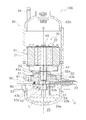
- FIG. 2 is a longitudinal sectional view schematically showing the rotary compressor 100 according to the first embodiment.
- expressions such as “up” and “down” may be used, but unless otherwise specified, the direction of the arrow U in FIG. The direction.
- the rotary compressor 100 is a device that sucks and compresses low-pressure refrigerant from the suction pipe 23 and discharges the high-pressure refrigerant from the discharge pipe 24.
- the rotary compressor 100 is supplied with an intermediate pressure refrigerant from the injection pipe 90.
- R32 is used as the refrigerant.
- the type of refrigerant is not limited to this.
- the casing 20 is a vertical cylindrical container.
- the casing 20 includes a cylindrical cylindrical member 21 that is open at the top and bottom, and a bowl-shaped upper lid 22 a and a lower lid 22 b that are provided at the upper and lower ends of the cylindrical member 21 and close the upper and lower open ends of the cylindrical member 21, respectively. (See FIG. 2).
- the cylindrical member 21, and the upper lid 22a and the lower lid 22b are fixed by welding so as to keep airtightness.
- a suction pipe 23 is provided below the cylindrical member 21.
- the suction pipe 23 is connected to the compression mechanism 50 and supplies the low-pressure refrigerant in the refrigerant circuit 10 to the compression chamber C ⁇ b> 1 of the compression mechanism 50.
- an injection pipe 90 is provided below the cylindrical member 21.
- the injection pipe 90 is connected to the compression mechanism 50 and supplies the intermediate pressure refrigerant in the refrigerant circuit 10 to the compression chamber C ⁇ b> 1 of the compression mechanism 50.
- the injection pipe 90 is connected to an injection refrigerant supply pipe 92.
- a discharge pipe 24 is provided on the upper part of the cylindrical member 21. The discharge pipe 24 discharges the high-pressure refrigerant compressed by the compression mechanism 50 to the refrigerant circuit 10 (not shown).
- An oil reservoir space 25 is formed in the lower part of the casing 20. Refrigerating machine oil L for lubricating the compression mechanism 50 and the like is stored in the oil reservoir space 25.
- the motor 30 is a mechanism that drives the compression mechanism 50. As shown in FIG. 2, the motor 30 is accommodated in a central portion in the vertical direction of the casing 20. The motor 30 is disposed above the compression mechanism 50.
- the motor 30 mainly includes a stator 31 and a rotor 32.
- the rotor 32 is a cylindrical member.
- the rotor 32 is arranged inside the stator 31 formed in an annular shape with a slight gap from the stator 31.
- the drive shaft 40 is inserted into the hollow portion of the rotor 32.
- the rotor 32 rotates in response to a magnetic force generated by a current flowing through a winding (not shown) wound around the stator 31.
- a driving force is applied from the motor 30 to the compression mechanism 50 via the drive shaft 40.
- the drive shaft 40 has an eccentric portion 41 that is eccentric with respect to the axis O of the drive shaft 40. And the eccentric part 41 is connected with the piston 61 mentioned later.
- the piston 61 is disposed in a space surrounded by the cylinder hole 51d of the cylinder 51 of the compression mechanism 50.
- the eccentric portion 41 is fitted in the cylindrical piston 61 in a state where the force of the motor 30 can be transmitted.
- the drive shaft 40 is rotatably supported by an upper bearing portion 52a of the front head 52 and a lower bearing portion 53a of the rear head 53 of the compression mechanism 50 described later.
- the drive shaft 40 rotates around the axis O when the motor 30 is driven.
- the eccentric part 41 rotates eccentrically with respect to the shaft center O, and makes the piston 61 of the compression mechanism 50 revolve.
- the oil pump 42 for sucking the refrigerating machine oil L in the oil reservoir space 25 is fixed to the lower end portion of the drive shaft 40.
- An oil supply passage 43 through which the refrigerating machine oil L sucked by the oil pump 42 flows is formed inside the drive shaft 40 (see FIG. 2).
- the oil supply passage 43 has a main oil supply passage 43 a extending in the vertical direction along the drive shaft 40.
- the oil supply passage 43 has a plurality of sub oil supply passages (not shown) extending from the main oil supply passage 43a to the outer side in the radial direction of the drive shaft 40.
- the auxiliary oil supply passage opens to the side surface of the drive shaft 40 in the vicinity of the lower end of the upper bearing portion 52a, in the vicinity of the upper end of the lower bearing portion 53a, and in the eccentric portion 41 to form a plurality of oil supply ports 43b.
- Refrigerating machine oil L sucked by the oil pump 42 from the oil reservoir space 25 passes through the main oil supply passage 43a and the auxiliary oil supply passage, and is supplied from the oil supply port 43b to the sliding portions of the drive shaft 40 and the piston 61. .
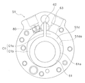
- FIG. 3 is a plan view schematically showing the configuration of the cylinder 51.
- the cylinder 51 is disposed inside the casing 20 so that the axial direction extends in the vertical direction.
- the upper and lower ends of the cylinder 51 are open, and a cylindrical cylinder hole 51d (a hollow portion of the cylindrical cylinder 51) is formed inside.
- the piston 61 is accommodated in the cylinder hole 51d.
- a bush holding hole 51a into which the bush 63 is rotatably inserted and an oil supply hole 51b communicating with the bush holding hole 51a are formed on the outer peripheral side of the cylinder hole 51d. Further, a suction passage 51c communicating with the cylinder hole 51d is formed in the cylinder 51.
- the suction passage 51c is formed through the cylinder 51 along the radial direction from the outer peripheral surface of the cylinder 51 to the cylinder hole 51d. Thereby, it communicates with the suction passage 51c and the cylinder hole 51d.
- the distal end portion of the suction pipe 23 is inserted into the suction passage 51c. Then, the refrigerant is guided from the suction pipe 23 to the compression chamber C1 formed in the cylinder hole 51d through the suction passage 51c.
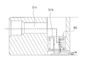
- the cylinder 51 is formed with an injection passage 51r communicating with the compression chamber C1 and a storage portion 51k for storing a valve assembly 80 described later.
- the injection passage 51r is formed so as to extend the cylinder 51 in the horizontal direction.
- the injection pipe 90 is inserted and fixed in the injection passage 51r.
- the storage unit 51k is a space between the injection pipe 90 and the compression chamber C1, and a refrigerant having an intermediate pressure (an intermediate pressure between high pressure and low pressure) flowing from the injection pipe 90 passes through the storage unit 51k. It is supplied to the compression chamber C1.
- a cylindrical upper bearing portion 52 a that rotatably supports the drive shaft 40 is formed on the upper portion of the front head 52.
- the rear head 53 is disposed below the cylinder 51 as shown in FIG.
- the rear head 53 closes the opening below the cylinder 51. In other words, the opening below the cylinder hole 51d of the cylindrical cylinder 51 is closed.
- the rear head 53 forms a bottom surface of the compression chamber C1 formed between the inner peripheral surface 51da of the cylinder 51 and the outer peripheral surface 61a of the piston 61 disposed in the cylinder hole 51d.
- the rear head 53 is formed with an oil supply communication hole 53b that communicates with a space surrounded by the oil supply hole 51b of the cylinder 51.
- the oil supply communication hole 53b penetrates the rear head 53 in the vertical direction.
- the oil supply communication hole 53 b communicates with a flow path 54 a formed in the oil pickup 54 attached to the lower portion of the rear head 53.
- the lower end of the oil pickup 54 is disposed in the oil reservoir space 25.
- the refrigerating machine oil L in the oil reservoir space 25 is supplied into the oil supply hole 51b through the flow path 54a and the oil supply communication hole 53b due to a pressure difference.
- Piston The piston 61 is a member formed in a cylindrical shape as shown in FIG.
- the piston 61 is formed integrally with the blade 62.
- the eccentric portion 41 of the drive shaft 40 is fitted into the piston 61.
- the blade 62 is a member that partitions the compression chamber C1 into a low pressure chamber C1a and a high pressure chamber C1b.
- the blade 62 is a plate-like member formed integrally with the piston 61.
- the blade 62 is formed so as to extend from the outer peripheral surface 61a of the cylindrical piston 61 toward the radially outer side.
- the blade 62 is sandwiched between a pair of bushes 63 disposed in the bush holding hole 51 a of the cylinder 51, and is supported by the bush 63 so as to be swingable.
- the blade 62 supported by the bush 63 swings, and enters and exits the bush holding hole 51a and the oil supply hole 51b according to the eccentric rotation of the piston 61.
- the rotation of the piston 61 is restricted by the blade 62.
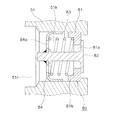
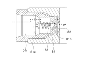
- valve assembly 80 is provided between the compression chamber C1 and the injection pipe 90 and functions as a check valve. Specifically, as shown in FIG. 5, the valve assembly 80 includes an opening forming member 81, a valve main body 82, a spring member 83, and a spring receiving member (movable member) 84.
- the outflow direction d1 of the intermediate pressure refrigerant flowing out of the opening 81a and the outflow direction d2 of the intermediate pressure refrigerant flowing out of the injection passage 51r into the compression chamber C1 are substantially horizontal.
- the valve assembly 80 is stored in the storage unit 51k.
- the holding portion 81b engages with a spring receiving member 84, which will be described later, and restricts the movement of the spring receiving member 84. Since the outer periphery of the opening forming member 81 is in close contact with the storage portion 51k, the reverse flow of the refrigerant from the compression chamber C1 is prevented when the opening 81a is closed.
- valve body 82 moves in accordance with the difference between the pressure of the intermediate pressure refrigerant supplied from the injection pipe 90 and the pressure of the refrigerant in the compression chamber C1 during compression.
- the valve body 82 moves from the compression chamber C1 side to the injection pipe 90 side, the valve body 82 closes the opening 81a of the opening forming member 81.
- the spring member 83 is disposed on the injection pipe 90 side with respect to the opening 81a, and applies force to the valve main body 82 in the direction of the injection pipe 90 side.
- the spring member 83 is a push spring.
- the spring member 83 is installed inside the holding portion 81 b of the opening forming member 81 and the holding portion 84 c of the spring receiving member 84 so as to surround the valve shaft portion 82 b.
- FIG. 9 is a schematic diagram showing the configuration of the spring receiving member 84.
- FIG. 9A schematically shows a plan view of the spring receiving member 84
- FIG. 9B shows a CC cross-sectional view of FIG. 9A.
- the spring receiving member 84 has a flat bottom surface portion 84d.
- the bottom surface portion 84d is a portion that contacts the pressing spring of the spring member 83, and a pressing spring load is applied.
- the bottom surface portion 84d has a channel opening 84a and a connecting hole 84b.
- the valve shaft portion 82b of the valve body is inserted and fixed in the connecting hole 84b.
- the spring receiving member 84 is connected to the valve body 82 on the injection pipe 90 side with respect to the opening 81a. With such a structure, the spring load received by the spring receiving member 84 is transmitted to the valve body 82. Further, as shown in FIG. 9B, the spring receiving member 84 has a U-shaped cylindrical shape in cross section, and the holding portion 84c is formed on the circumferential portion of the bottom surface portion 84d.
- the motor 30 is started. Thereby, the rotor 32 rotates with respect to the stator 31, and the drive shaft 40 fixed to the rotor 32 rotates.
- the eccentric portion 41 of the drive shaft 40 rotates eccentrically.
- the piston 61 in which the eccentric portion 41 is fitted is revolved along the cylinder hole 51 d of the cylinder 51. At this time, the rotation of the piston 61 is regulated by a blade 62 formed integrally with the piston 61.
- the piston 61 starts rotating from the state of FIG. 11 at the top dead center (clockwise in FIG. 11). Then, the refrigerant suction process from the suction passage 51c to the low pressure chamber C1a is started. As the rotation angle of the drive shaft 40 increases, the volume of the low pressure chamber C1a increases (see FIGS. 12 to 14), and the amount of refrigerant sucked into the low pressure chamber C1a increases. Then, when the piston 61 rotates to the top dead center, the refrigerant is closed in the low pressure chamber C1a.
- the low-pressure chamber C1a connected to the suction passage 51c shifts to the high-pressure chamber C1b connected to a discharge passage (not shown) formed in the front head 52.
- the volume of the high pressure chamber C1b decreases (see FIGS. 12 to 14).
- the pressure in the high pressure chamber C1b increases.
- a discharge valve (not shown) provided in the discharge passage is opened. Thereafter, the refrigerant in the high pressure chamber C1b is discharged into the internal space of the casing 20 through the discharge passage.
- the compressed refrigerant is discharged to the outside of the rotary compressor 100 through the discharge pipe 24.
- the discharge stroke of the refrigerant continues until the rotation angle of the piston 61 reaches 360 degrees.
- the suction stroke and the discharge stroke described above are repeated, and the refrigerant suction / compression operation is continuously performed.
- the valve assembly 80 uses the spring member 83 disposed on the injection pipe 90 side with respect to the opening 81a to close the opening 81a.
- the dead volume of the injection passage 51r between the compression chamber C1 and the compression chamber C1 can be reduced.
- it can reduce that the compressed refrigerant
- the back flow of the compressed refrigerant to the low pressure side compression chamber can be reduced, and the rotary compressor 100 with high compression efficiency can be provided.
- the valve assembly 80 further includes a spring receiving member 84 (movable part) connected to the valve main body 82 on the injection piping 90 side with respect to the opening 81a.
- the spring member 83 is a push spring. Then, the spring receiving member 84 receives a pressing spring load by the spring member 83.
- the valve assembly 80 which can move a valve main body using a push spring can be provided.
- the compression mechanism 50 includes an injection passage 51r through which the intermediate-pressure refrigerant flows into the compression chamber C1, and a storage portion 51k that stores the valve assembly 80. Then, in the storage portion 51k, the outflow direction d1 of the intermediate pressure refrigerant flowing out of the opening 81a of the opening forming member 81 and the outflow direction d2 of the intermediate pressure refrigerant flowing out of the injection passage 51r into the compression chamber C1 are substantially horizontal.
- the valve assembly 80 is stored.
- the intermediate pressure refrigerant flows linearly from the injection pipe 90 to the compression chamber C1, the intermediate pressure refrigerant can be supplied promptly when the opening 81a is opened.
- the compression mechanism 50 can be provided with an injection passage 51r by forming a through hole in the radial direction of the cylinder 51.
- the rotary compressor 100 of the said structure can be manufactured only by fitting the valve assembly 80 in this through-hole. Therefore, with such a configuration, the rotary compressor 100 with high compression efficiency can be easily manufactured.
- the storage portion 51k that stores the valve assembly 80 has an outlet direction d1 of the intermediate-pressure refrigerant that flows out of the opening 81a of the opening forming member 81, and an injection.
- the opening 81a can be gently opened with respect to the pressure change in the compression chamber C1. Thereby, it is possible to suppress the intermediate pressure refrigerant from flowing back into the suction pipe 23. As a result, the rotary compressor 100 with high compression efficiency can be provided. Further, the opening forming member and the cylinder can be integrated into one member, and the number of parts can be reduced.
- the spring member 83 is a push spring, but the spring member according to this embodiment is not limited to this.
- the spring member 83 may be a tension spring that is connected to the valve body 82 from the injection pipe 90 side with respect to the opening 81a. Even with such a configuration, the distance between the injection pipe 90 and the compression chamber C1 can be shortened. Therefore, the dead volume Vd can be reduced, and the rotary compressor 100 with high compression efficiency can be provided.
- the rotary compressor 100 is a 1 cylinder type rotary compressor, the compressor which concerns on this embodiment is not limited to this.
- the rotary compressor may be a multi-cylinder type (for example, 2 cylinder side) rotary compressor.
- a compressor is a 1 cylinder type rotary compressor
- the compressor which concerns on this embodiment is not limited to this. That is, any compressor may be used as long as the valve assembly 80 according to the present embodiment can be mounted.
- the valve assembly 80 according to the present embodiment can be mounted also in a scroll compressor.
- FIG. 19 is a schematic view of an air conditioner 1A using a rotary compressor 200 according to the second embodiment of the present invention. Also in the second embodiment, a refrigerant circuit similar to that in the first embodiment is realized.
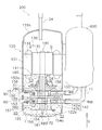
- FIG. 20 is a schematic longitudinal sectional view of a rotary compressor 200 according to the second embodiment.
- FIG. 21 is a schematic cross-sectional view of the front cylinder 151 as viewed in the direction of arrows XXI-XXI in FIG. 22 is a schematic cross-sectional view of the rear cylinder 153 as viewed in the direction of arrows XXII-XXII in FIG.
- a casing 120 of the rotary compressor 200 includes, as shown in FIG. 20, a cylindrical member 121 having an open top and bottom, and an upper lid 122a provided above the cylindrical member 121. And a lower lid 122b provided below the cylindrical member 121.
- the lower part of the cylindrical member 121 is provided with two suction pipes 23 that penetrate the lower side surface of the cylindrical member 121.
- a discharge pipe 24 for discharging the compressed refrigerant is provided through the upper lid 122a.
- the casing 120 mainly supports the motor 130, the rotary compression mechanism 150 disposed below the motor 130, the drive shaft 140 connecting the motor 130 and the rotary compression mechanism 150, and the drive shaft 140.
- the upper bearing portion 160 and the lower bearing portion 170 are accommodated.
- the drive shaft 140 is disposed so as to extend in the vertical direction along the center line of the cylindrical member 121.
- an oil reservoir space 125 for storing the refrigerating machine oil L shown in FIG. 20 is formed at the bottom of the casing 120.
- the refrigerator oil L is used for lubricating the rotary compression mechanism 150, the upper bearing portion 160, the lower bearing portion 170, and the like.
- the rotary compressor 200 is a so-called high pressure dome type compressor.
- the oil reservoir space 125 communicates with a compression chamber S1b on the high pressure side of the front cylinder 151 and a compression chamber S2b on the high pressure side of the rear cylinder 153, which will be described later, via the high pressure space S3.
- the motor 130 is provided to drive the rotary compression mechanism 150 disposed below.
- the motor 130 is operated in a wide speed range from low speed to high speed.
- the motor 130 includes a stator 131 and a rotor 132.
- the stator 131 is an annular member and is fixed to the inner wall surface of the cylindrical member 121 of the casing 120.
- the rotor 132 is rotatably disposed in the internal space of the stator 131 via the stator 131 and the air gap space G.
- An upper portion of the main shaft 141 of the drive shaft 140 extending in the vertical direction is fixed to the center portion of the rotor 132, and the rotor 132 and the drive shaft 140 are coupled.
- the motor 130 rotates the rotor 132 by a magnetic force generated between the stator 131 and the rotor 132, and drives the rotary compression mechanism 150 via the drive shaft 140.
- the drive shaft 140 includes a columnar main shaft 141 extending along the central axis of the cylindrical member 121 of the casing 120 and an eccentric portion 142 that is eccentric with respect to the main shaft 141. Further, the drive shaft 140 is formed with an oil supply path 180 for supplying the oil L stored in the oil reservoir space 125 to the rotary compression mechanism 150, the upper bearing portion 160, and the lower bearing portion 170.
- the eccentric portion 142 includes a first eccentric portion 142a and a second eccentric portion 142b that is eccentric with the first eccentric portion 142a by shifting the phase by 180 °.
- the first eccentric portion 142a is rotatably fitted inside a piston main body 152a described later. That is, the drive shaft 140 is connected to the piston 152 via the first eccentric portion 142a.
- the first eccentric portion 142a is formed with a first contact surface 142aa that comes into contact with the inner surface of the piston body portion 152a.
- the second eccentric portion 142b is rotatably fitted inside a piston main body 154a described later. That is, the drive shaft 140 is connected to the piston 154 via the second eccentric portion 142b.
- the second eccentric portion 142b is formed with a second contact surface 142ba that comes into contact with the inner surface of the piston main body 154a.
- the oil supply path 180 has a suction portion 181, an oil supply main path 182, and an oil supply sub-path 183.
- the suction part 181 is a hollow member whose lower end is disposed in the oil reservoir space 125.
- the oil supply main path 182 communicates with the oil reservoir space 125 through the suction portion 181 and is formed inside the drive shaft 140 along the central axis of the cylindrical member 121 of the casing 120.
- the oil supply sub-path 183 is formed by branching from the oil supply main path 182.
- the rotary compression mechanism 150 is a two-cylinder compression mechanism having two cylinders.
- the rotary compression mechanism 150 compresses and discharges the refrigerant sucked from the suction pipe 23.
- the rotary compression mechanism 150 mainly includes a front cylinder 151, a piston 152, a rear cylinder 153, a piston 154, a middle plate 155, a front head 156, a rear head 157, a front muffler 158, and a rear muffler 159.
- the rear cylinder 153 and the piston 154 are disposed below the front cylinder 151.
- the middle plate 155 is disposed between the front cylinder 151 and the rear cylinder 153.
- the front head 156 and the rear head 157 are provided so as to sandwich the front cylinder 151 and the rear cylinder 153 from above and below.
- the front muffler 158 is disposed above the front head 156.
- the rear muffler 159 is disposed below the rear head 157.
- the suction hole 151a penetrates the front cylinder 151 in the radial direction, and communicates the suction pipe 23 and the compression chamber S1a on the low pressure side.
- the bush accommodation hole 151b is a cylindrical hole that penetrates the front cylinder 151 in the plate thickness direction.
- a pair of semicircular bushes 1511 are accommodated in the bush accommodation holes 151b so as to sandwich a blade 152b of a piston 152 described later.
- the bush 1511 is attached to the front cylinder 151 so as to be swingable.
- the blade accommodation hole 151c is a cylindrical hole that penetrates the front cylinder 151 in the plate pressure direction, and communicates with the bush accommodation hole 151b.
- the piston 152 is disposed in the front cylinder 151 and forms the low pressure side and high pressure side compression chambers S1a and S1b in the cylinder space S1 of the front cylinder 151. As the piston 152 rotates eccentrically, the refrigerant sucked into the compression chamber S1a on the low pressure side is compressed in the compression chamber S1b on the high pressure side.
- the rear cylinder 153 has a cylinder space (compression chamber) S2, a suction hole 153a, a bush accommodation hole 153b, and a blade accommodation hole 153c.
- the cylinder space S2 is a space surrounded by the rear cylinder 153, the rear head 157, and the middle plate 155.
- a piston 154 is disposed in the cylinder space S2, and the piston 154 allows a low-pressure side compression chamber S2a that communicates with a suction hole 153a and a high-pressure side compression chamber that communicates with a discharge hole 157a formed in a rear head 157 described later.
- S2b is partitioned.
- the suction hole 153a penetrates the rear cylinder 153 in the radial direction, and communicates the suction pipe 23 and the compression chamber S2a on the low pressure side.
- the bush accommodation hole 153b is a cylindrical hole that penetrates the rear cylinder 153 in the plate pressure direction.
- a pair of semicircular bushes 1531 are accommodated in the bush accommodation holes 153b so as to sandwich a blade 154b of a piston 154 described later.
- the bush 1531 is swingably attached to the rear cylinder 153.
- the blade accommodation hole 153c is a cylindrical hole that penetrates the rear cylinder 153 in the plate pressure direction, and communicates with the bush accommodation hole 153b.
- the piston 154 is disposed in the rear cylinder 153, and forms the low pressure side and high pressure side compression chambers S2a and S2b in the cylinder space S2 of the rear cylinder 153. As the piston 154 rotates eccentrically, the refrigerant sucked into the compression chamber S2a on the low pressure side is compressed in the compression chamber S2b on the high pressure side.
- the piston 154 includes an annular piston main body 154a and a flat blade 154b extending radially outward from the piston main body 154a.
- the second eccentric portion 142b of the drive shaft 140 is inserted into the piston main body portion 154a.
- the piston main body 154a performs an eccentric rotational movement while being in sliding contact with the inner peripheral surface of the rear cylinder 153, and the blade 154b swings and at the same time moves forward and backward along the longitudinal direction.
- the refrigerant sucked into the low-pressure side compression chamber S2a from the suction pipe 23 is compressed in the high-pressure side compression chamber S2b by the piston main body 154a, and from the discharge hole 157a formed in the rear head 157 described later, from the muffler space S5. Discharged.
- the middle plate 155 is disposed between the front cylinder 151 and the rear cylinder 153 as shown in FIG.
- the middle plate 155 closes the opening below the cylinder space S1 of the front cylinder 151 and closes the opening above the cylinder space S2 of the rear cylinder 153.
- the front head 156 is disposed above the front cylinder 151.
- the front head 156 closes the opening above the cylinder space S1 of the front cylinder 151.
- the front head 156 is integrally formed with an upper bearing portion 160 that pivotally supports a drive shaft 140 extending in the vertical direction.
- the upper bearing portion 160 will be described later.
- the front head 156 is formed with a discharge hole 156a for discharging the refrigerant in the high-pressure side compression chamber S1b compressed by the eccentric rotation drive of the piston 152 to the muffler space S4 described later (see FIG. 21).
- the discharge hole 156a is formed so as to penetrate the front head 156 in the vertical direction.
- a discharge valve (not shown) is disposed above the discharge hole 156a.
- the rear head 157 is disposed below the rear cylinder 153.
- the rear head 157 closes the opening below the cylinder space S2 of the rear cylinder 153.
- the rear head 157 is integrally formed with a lower bearing portion 170 that supports a drive shaft 140 that extends in the vertical direction. The lower bearing portion 170 will be described later.
- a discharge hole (not shown) is formed in order to discharge the refrigerant from the muffler space S4.
- the refrigerant in the muffler space S4 passes through a discharge hole (not shown) and is discharged to the high pressure space S3 above the front muffler 158, that is, above the front head 156.
- the refrigerant discharged into the high-pressure space S3 passes through the air gap space G between the stator 131 and the rotor 132 of the motor 130, moves upward in the casing 120, and is discharged from the discharge pipe 24.
- the refrigerant in the muffler space S5 flows into the muffler space S4 through a communication hole (not shown) formed by communicating the rear head 157, the rear cylinder 153, the middle plate 155, the front cylinder 151, and the front head 156.
- the upper bearing part 160 is formed integrally with the front head 156, and supports the drive shaft 140 extending in the vertical direction. That is, the drive shaft 40 is inserted into the central opening of the upper bearing portion 160.
- the lower bearing part 170 is formed integrally with the rear head 157, and supports the drive shaft 140 extending in the vertical direction. That is, the drive shaft 140 is inserted into the central opening of the lower bearing portion 170.
- the valve assembly 280 includes the intermediate pressure refrigerant flowing out from the opening 281a of the opening forming member 281 and the intermediate pressure flowing out from the injection passages 151r and 153r into the compression chamber.
- the refrigerant is stored in the storage portions 151k and 153k in the cylinders 151 and 153 so that the outflow direction d2 of the refrigerant is substantially horizontal.
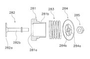
- the opening forming member 281 has a plate-like portion where the opening 281a is formed, like the opening forming member 81 according to the first embodiment.
- the opening 281a is closed by being in close contact with a flat plate portion 282a of a valve body 282, which will be described later. Since the outer periphery of the opening forming member 281 is in close contact with the storage portion 151k, the reverse flow of the refrigerant from the compression chamber is prevented when the opening 281a is closed.
- the opening forming member 281 has a cylindrical portion 281b.
- the cylindrical portion 281b is provided so as to surround a valve shaft portion 282b described later.
- a spring member 283 is disposed outside the cylindrical portion 281b.
- the cylindrical portion 281b engages with a spring receiving member 284, which will be described later, and restricts the movement of the spring member 283.
- the valve body 282 has a flat plate portion 282a. Further, the valve main body 282 is provided with a rod-shaped valve shaft portion 282b on the central axis of the flat plate portion 282a. The valve shaft portion 282 b passes through the opening 281 a of the opening forming member 281 and is connected to the spring receiving member 284. Thereby, the valve main body 282 also moves according to the movement of the spring receiving member 284 to which the spring load is applied. Specifically, the valve main body 282 moves according to the difference between the pressure of the intermediate pressure refrigerant supplied from the injection pipe 90 and the pressure of the refrigerant in the middle of compression in the compression chamber. The valve body 282 closes the opening 281a of the opening forming member 281 when moved from the compression chamber side to the injection pipe 90 side.
- the spring member 283 is disposed on the injection pipe 90 side with respect to the opening 281a, and applies force to the valve body 282 in the direction of the injection pipe 90.
- a push spring is employed as the spring member 283.
- the spring member 283 is disposed outside so as to surround the cylindrical portion 281b.
- the spring receiving member 284 is a flat plate member having a diameter larger than that of the spring member 283.
- the spring receiving member 284 is a portion in contact with the pressing spring of the spring member 283, and a pressing spring load is applied.
- the spring receiving member 284 has a flow path opening 284a and a connecting hole 284b.
- the valve shaft portion 282b of the valve body is inserted and fixed in the connection hole 284b. That is, the spring receiving member 284 is connected to the valve body 282 on the injection pipe 90 side with respect to the opening 281a. With such a structure, the spring load received by the spring receiving member 284 is transmitted to the valve body 282.
- the stopper portion 285 is a member that is screwed into an end portion of the valve shaft portion 282b on the injection pipe 90 side. By fixing the stop portion 285 to the valve shaft portion 282b, the opening forming member 281, the valve main body 282, the spring member 283, and the spring receiving member 284 are integrated.
- the motor 130 is started. Thereby, the rotor 132 rotates with respect to the stator 131, and the drive shaft 140 fixed to the rotor 132 rotates.
- the piston 152 and the piston 154 connected to the first eccentric portion 142a and the second eccentric portion 142b of the drive shaft 140 are driven.
- the refrigerant is compressed in the front cylinder 151 and the rear cylinder 153 and discharged to the muffler spaces S4 and S5.
- the first contact surface 142aa of the first eccentric portion 142a comes into sliding contact with the inner peripheral surface of the annular piston main body 152a.
- the blade 152b of the piston 152 oscillates and at the same time moves forward and backward along the longitudinal direction, and the piston main body 152a moves eccentrically.
- the outer peripheral surface of the piston main body 152a is in sliding contact with the inner peripheral surface of the front cylinder 151.
- a compression chamber S1a on the low pressure side communicating with the suction hole 151a is defined in the front cylinder 151, and the refrigerant is sucked from the accumulator 6.
- the refrigerant is compressed in the high-pressure side compression chamber S1b communicating with the discharge hole 156a, and when a predetermined pressure is reached, the discharge valve disposed above the discharge hole 156a is pushed up to be discharged into the muffler space S4.
- the refrigerant discharged into the muffler space S4 flows into the high-pressure space S3 formed above the front head 156, passes through the air gap space G between the stator 131 and the rotor 132 of the motor 130, and passes through the casing 120. It moves upward and is discharged from the discharge pipe 24.
- the refrigerant is discharged from the compression chamber S2b to the muffler space S5.
- the refrigerant discharged from the rear cylinder 153 once flows into the muffler space S4. And it discharges from the discharge pipe 24 through the same path
- intermediate pressure refrigerant is injected into the compression chambers S1b and S2b in the middle of compression via the injection passages 151r and 153r. Specifically, when the pressure in the injection passages 151r and 153r is higher than that in the compression chambers S1b and S2b, the intermediate pressure refrigerant is injected from the injection passages 151r and 153r into the compression chambers S1b and S2b. On the other hand, when the pressure in the compression chambers S1b and S2b becomes higher and the pressure in the compression chambers S1b and S2b becomes higher than that in the injection passage 151r, the valve assembly 280 provided in the injection passages 151r and 153r is closed and the intermediate pressure is increased. The supply of refrigerant is stopped. As described above, in the rotary compressor 200 according to the present embodiment, the compression efficiency is increased by injecting the intermediate pressure refrigerant.
- the oil supply path 180 uses the pressure difference between the compression chambers S1a, S1b of the front cylinder 51 and the oil reservoir space 125 and the pressure difference between the compression chambers S2a, S2b of the rear cylinder 153 and the oil reservoir space 125.
- the refrigerating machine oil L is transferred. Thereby, the refrigerating machine oil L in the oil reservoir space SL is supplied to the rotary compression mechanism 150 through the oil supply path 180.
- the rotary compressor 200 compresses the low-pressure refrigerant in the compression chambers S1 and S2 into the high-pressure refrigerant, and the intermediate-pressure refrigerant in the compression chambers S1 and S2.
- An injection pipe 90 for supplying, and a valve assembly 280 provided between the compression chambers S1 and S2 and the injection pipe 90 are provided.
- the valve assembly 280 includes an opening forming member 281, a valve main body 282, and a spring member 283.
- the opening forming member 281 forms the opening 281a.
- the valve body 282 moves according to the difference between the pressure of the refrigerant supplied from the injection pipe 90 and the pressure of the refrigerant in the compression chambers S1 and S2 during compression, and moves from the compression chambers S1 and S2 side to the injection pipe 90 side.
- the opening 281a is closed.
- the spring member 283 is disposed on the injection pipe 90 side with respect to the opening 281a, and applies force to the valve body 282 in the direction of the injection pipe 90.
- the valve assembly 280 uses the spring member 283 disposed on the injection pipe 90 side with respect to the opening 281a to close the opening 281a. And dead volume of the injection passage 151r between the compression chambers S1 and S2 can be reduced. Thereby, it can reduce that the compressed refrigerant
- the valve assembly 280 further includes a spring receiving member 284 (movable part) connected to the valve main body 282 on the injection pipe 90 side with respect to the opening 281a.
- the spring member 283 is a push spring.
- the spring receiving member 284 receives a pressing spring load by the spring member 283.
- the valve assembly 280 which can move a valve main body using a push spring can be provided.
- the opening forming member 281 further has a cylindrical portion 281b that communicates with the opening 281a and into which the valve main body 282 (valve shaft portion 282b) is inserted.
- the spring member 283 is arrange
- the cylindrical portion (tubular portion) 281b of the opening forming member 281 engages with the spring receiving member 284 (movable portion) to restrict the movement of the spring receiving member 284. It has a contact part.
- the spring receiving member 284 is connected to the valve shaft portion 282b. Therefore, it is possible to avoid the valve body 282 from moving more than necessary by the spring member 283. For example, the valve main body 282 can be prevented from jumping out from the storage portions 151k and 153k to the compression chambers S1 and S2.
- the spring receiving member 284 (movable part) has a flow path opening 284a. Therefore, the intermediate pressure refrigerant flowing from the injection pipe 90 can be supplied to the compression chambers S1 and S2 through the inside of the valve assembly 280.
- the front cylinder 151 and the rear cylinder 153 have injection passages 151r and 153r through which the intermediate-pressure refrigerant flows into the compression chambers S1 and S2, and storage portions 151k and 153k that store the valve assembly 280.
- the storage portions 151k and 153k have an outlet direction d1 of the intermediate pressure refrigerant flowing out of the opening 281a of the opening forming member 281 and an outlet direction d2 of the intermediate pressure refrigerant flowing out of the injection passages 151r and 153r into the compression chambers S1 and S2.
- the valve assembly 280 is stored so that is substantially horizontal.
- the intermediate pressure refrigerant flows linearly from the injection pipe 90 to the compression chambers S1, S2, the intermediate pressure refrigerant can be supplied quickly when the opening 281a is opened.
- the compression mechanism 150 can provide the injection passages 151r and 153r by forming through holes in the radial direction of the front cylinder 151 and the rear cylinder 153.
- the rotary compressor 200 of the said structure can be manufactured only by fitting the valve assembly 280 in this through-hole. Therefore, with such a configuration, the rotary compressor 200 with high compression efficiency can be easily manufactured.
- valve assembly 280 is used, but the present invention is not limited to this.
- valve assembly 80 having the shape used in the first embodiment and its modifications may be used.
- the rotary compressor 200 may protrude from the cylinders 151 and 153 into the compression chambers S1 and S2 when at least a part of the valve body 282 does not block the opening 281a of the opening forming member 281. .
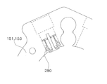
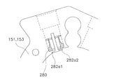
- the rotary compressor 200 is configured so that the pistons 152 and 154 and the valve body 282 do not collide. Therefore, generally, as shown in FIG. 26 (a), the rotary compressor 200 is configured such that the valve main body 282 has the storage portion 151k of the cylinders 151 and 153 even when the valve assembly 280 is open. , 153k space. However, when the valve assembly 280 is provided in the vicinity of the discharge holes 156a and 157a, even if the valve body 282 protrudes into the compression chambers S1 and S2, it collides with the pistons 152 and 154 located in the vicinity of the suction holes 151a and 153a. There is nothing. Therefore, as shown in FIG.
- the rotary compressor 200 according to the modified example 2C is configured to protrude only one end (282a2) with respect to the inner peripheral surface, when forming the injection passages 151r and 153r, a little from the center of the cylinders 151 and 153. It is necessary to form through holes in the shifted direction. Therefore, the manufacturing difficulty is high.
- the injection passages 151r and 153r can be formed by forming the through holes toward the centers of the cylinders 151 and 153. Therefore, the rotary compressor 200 according to the modified example 2D can be operated not only safely but more easily than the rotary compressors according to the modified examples 2B and 2C.
- the opening forming member 281 and the cylinders 151 and 153 are formed of different members. However, they may be formed of the same member. By integrating the opening forming member 281 and the cylinders 151 and 153 into one member, the number of parts can be reduced.
- the present invention is not limited to the above embodiments as they are.
- the present invention can be embodied by modifying the components without departing from the scope of the invention in the implementation stage. Further, the present invention can form various inventions by appropriately combining a plurality of constituent elements disclosed in the above embodiments. For example, some components may be deleted from all the components shown in the embodiment. Furthermore, constituent elements may be appropriately combined in different embodiments.
Landscapes
- Engineering & Computer Science (AREA)
- Mechanical Engineering (AREA)
- General Engineering & Computer Science (AREA)
- Applications Or Details Of Rotary Compressors (AREA)
- Compressor (AREA)
Abstract
圧縮効率の高い圧縮機を提供する。弁組立体(280)は、圧縮室(S1,S2)とインジェクション配管(90)との間に設けられる。ここで、弁組立体(280)は、開口形成部材(281)と、弁本体(282)と、バネ部材(283)と、を有する。開口形成部材(281)は、開口(281a)を形成するものである。弁本体(282)は、インジェクション配管(90)から供給される冷媒の圧力と圧縮室(S1,S2)内の圧縮途中の冷媒の圧力との差に応じて移動し、圧縮室(S1,S2)側からインジェクション配管(90)側に移動したときに、開口(281a)を塞ぐ。バネ部材(283)は、開口(281a)に対してインジェクション配管(90)側に配置され、弁本体(282)に対してインジェクション配管(90)側の向きに力を加える。
Description
本発明は、圧縮機及び弁組立体に関する。
近年、中間圧冷媒のインジェクションを行なう圧縮機が普及している。通常、中間圧冷媒のインジェクションを行なう種類の圧縮機では、インジェクション配管と圧縮機構との間のインジェクション通路に逆止弁が設けられる(例えば、特許文献1(中国特許出願公開第103423163号明細書))。
しかしながら、上述した種類の圧縮機では、逆止弁閉塞時に、インジェクション通路における、逆止弁よりも圧縮室側の空間に、圧縮された冷媒が溜まる。そして、この圧縮された冷媒が、低圧側圧縮室へ逆流することで再膨張および再圧縮を起こし、圧縮機の圧縮効率を低下させることがある。
本発明の課題は、圧縮効率の高い圧縮機を提供することである。
本発明の第1観点に係る弁組立体は、圧縮室内の低圧冷媒を圧縮して高圧冷媒にする圧縮機構と、圧縮室内に中間圧冷媒を供給するためのインジェクション配管と、を備える圧縮機に用いられる。また、弁組立体は、圧縮室とインジェクション配管との間に設けられる。ここで、弁組立体は、開口形成部材と、弁本体と、バネ部材と、を有する。開口形成部材は、開口を形成するものである。弁本体は、インジェクション配管から供給される冷媒の圧力と圧縮室内の圧縮途中の冷媒の圧力との差に応じて移動し、圧縮室側からインジェクション配管側に移動したときに、開口を塞ぐものである。バネ部材は、開口に対してインジェクション配管側に配置され、弁本体に対してインジェクション配管側の向きに力を加えるものである。
第1観点に係る弁組立体では、開口を塞ぐのに、開口に対してインジェクション配管側に配置されるバネ部材を用いるので、開口と圧縮室との間のインジェクション通路の死容積を小さくできる。これにより、インジェクション通路における開口部と圧縮室との間の空間に、圧縮された冷媒が溜まるのを低減できる。結果として、圧縮された冷媒の低圧側圧縮室への逆流を低減でき、圧縮効率の高い圧縮機を提供できる。
本発明の第2観点に係る弁組立体は、第1観点に係る弁組立体において、開口に対してインジェクション配管側に、弁本体と連結する可動部をさらに備える。ここで、バネ部材は、押しバネである。また、可動部がバネ部材により押しバネ荷重を受ける。
第2観点に係る弁組立体では、押しバネを用いて弁本体を動かすことができる。
本発明の第3観点に係る弁組立体は、第2観点に係る弁組立体において、開口形成部材が、バネ部材の周囲を囲って保持する保持部をさらに有する、
第3観点に係る弁組立体では、バネ部材が開口形成部材で保持されるので、バネ部材の離脱を阻止するとともに、一体構成の弁組立体を提供できる。
第3観点に係る弁組立体では、バネ部材が開口形成部材で保持されるので、バネ部材の離脱を阻止するとともに、一体構成の弁組立体を提供できる。
本発明の第4観点に係る弁組立体は、第3観点に係る弁組立体において、保持部が、可動部に係合して可動部の動きを規制する接触部を有する。
第4観点に係る弁組立体では、保持部が可動部の動きを規制するので、バネ部材により弁本体が必要以上に移動するのを回避できる。具体的には、弁本体がインジェクション配管から圧縮室に飛び出るのを回避できる。
本発明の第5観点に係る弁組立体は、第2観点の弁組立体において、開口形成部材が、筒状部をさらに有する。筒状部は、開口に連通し、弁本体が内部に挿入されるものである。また、バネ部材が、筒状部の周囲を囲うように配置される。
第5観点に係る弁組立体では、上記構成により、バネ部材の離脱を阻止するとともに、各部材が一体化された弁組立体を提供できる。
本発明の第6観点に係る弁組立体は、第5観点の弁組立体において、筒状部が、可動部に接触して可動部の動きを規制する接触部を有する。
第6観点に係る弁組立体では、筒状部が可動部の動きを規制するので、バネ部材により弁本体が必要以上に移動するのを回避できる。具体的には、弁本体がインジェクション配管から圧縮室に飛び出るのを回避できる。
本発明の第7観点に係る弁組立体は、第6観点の弁組立体において、接触部が、開口形成部材の開口に対してインジェクション配管側に配置される。
第7観点に係る弁組立体では、上記構成により、インジェクション配管側に配置される弁組立体を提供できる。
本発明の第8観点に係る弁組立体は、第2観点から第7観点のいずれかの弁組立体において、可動部が流路開口を有する。
第8観点に係る弁組立体では、可動部が流路開口を有するので、インジェクション配管から流入する中間圧冷媒を、弁組立体の内部を通過させて圧縮室に供給できる。
本発明の第9観点に係る弁組立体は、第1観点の弁組立体において、バネ部材が、開口に対してインジェクション配管側から、弁本体に連結する引きバネである。
第9観点に係る弁組立体では、引きバネを用いて弁本体を動かすことができる。
本発明の第10観点に係る圧縮機は、第1観点から第9観点のいずれかの弁組立体を有する。ここで、圧縮機機構は、圧縮室に中間圧冷媒を流出するインジェクション通路と、弁組立体を格納する格納部と、を有する。そして、格納部が、開口を流出する中間圧冷媒の流出方向と、インジェクション通路から圧縮室に流出する中間圧冷媒の流出方向とが略水平となるように、弁組立体を格納する。
第10観点に係る弁組立体では、インジェクション配管から圧縮室まで直線的に中間圧冷媒が流入するので、開口が開いたときに速やかに中間圧冷媒を供給できる。また、インジェクション通路を直線的に形成できるので、圧縮機の製造を簡易化できる。
本発明の第11観点に係る圧縮機は、第1観点から第9観点のいずれかの弁組立体を有する。ここで、圧縮機構は、圧縮室に中間圧冷媒を流出するインジェクション通路と、弁組立体を格納する格納部と、を有する。そして、格納部が、開口を流出する中間圧冷媒の流出方向と、インジェクション通路から圧縮室に流出する中間圧冷媒の流出方向とが略垂直となるように、弁組立体を格納する。
第11観点に係る弁組立体では、開口を圧縮室に対して直行する向きに配置できる。結果として、中間圧冷媒の流れが屈曲するので、圧縮室の圧力変化に対して緩やかに開口を開くことができる。また、開口形成部材とシリンダを一体部材とすることができ、部品点数を削減できる。
本発明の第12観点に係る圧縮機は、第1観点から第11観点の圧縮機が、ロータリ圧縮機である。
第12観点に係る弁組立体では、圧縮効率の高いロータリ圧縮機を提供できる。
本発明の第13観点に係るロータリ圧縮機は、第12観点のロータリ圧縮機において、圧縮機構が、シリンダと、ピストンとを有する。ピストンは、シリンダの内周面との間に圧縮室を形成し、シリンダの内周面に沿って偏心回転運動を行なう。また、開口形成部材はシリンダに格納される。そして、弁本体の少なくとも一部は、開口を塞いでいないときは、シリンダから圧縮室に突出している。なお、開口形成部材は、シリンダと一体部材であってもよい。
第13観点に係るロータリ圧縮機では、上記構成により、弁組立体と圧縮室との間の死容積を縮小できるので、圧縮効率をさらに高めることができる。
本発明の第14観点に係るロータリ圧縮機は、第13観点のロータリ圧縮機において、弁本体が、開口形成部材の開口より圧縮室側に平板状の平板部を有する。ここでは、平板部の中央部は圧縮室に突出している。一方、平板部の端部のうち、ピストンの回転運動に対向する側の端部は圧縮室に突出していない。
第14観点に係るロータリ圧縮機では、上記構成により、弁本体が正常に動かない場合でも、ピストンの回転による弁本体の損傷を回避できる。結果として、安全性の高いロータリ圧縮機を提供できる。
本発明の第15観点に係るロータリ圧縮機は、第13観点のロータリ圧縮機において、弁本体が、開口形成部材の開口より圧縮室側に平板状の平板部を有する。ここでは、平板部の中央部は圧縮室に突出している。一方、平板部の両端部は圧縮室に突出していない。
第15観点に係るロータリ圧縮機では、上記構成により、ピストンが逆回転する場合等においても、ピストンの回転による弁本体の損傷を回避できる。結果として、安全性の高いロータリ圧縮機を提供できる。
第1観点に係る弁組立体では、開口と圧縮室との間のインジェクション通路の死容積を小さくできる。結果として、圧縮効率の高い圧縮機を提供できる。
第2観点に係る弁組立体では、押しバネを用いて弁本体を動かすことができる。
第3観点に係る弁組立体では、バネ部材の離脱を阻止するとともに、一体構成の弁組立体を提供できる。
第4観点に係る弁組立体では、バネ部材により弁本体が必要以上に移動するのを回避できる。
第5観点に係る弁組立体では、バネ部材の離脱を阻止するとともに、各部材が一体化された弁組立体を提供できる。
第6観点に係る弁組立体では、バネ部材により弁本体が必要以上に移動するのを回避できる。
第7観点に係る弁組立体では、インジェクション配管側に配置される弁組立体を提供できる。
第8観点に係る弁組立体では、インジェクション配管から流入する中間圧冷媒を、弁組立体の内部を通過させて圧縮室に供給できる。
第9観点に係る弁組立体では、引きバネを用いて弁本体を動かすことができる。
第10観点に係る弁組立体では、インジェクション配管から圧縮室まで直線的に中間圧冷媒が流入するので、開口が開いたときに速やかに中間圧冷媒を供給できる。
第11観点に係る弁組立体では、開口を圧縮室に対して直行する向きに配置することで、部品点数を減らせる。
第12観点に係る弁組立体では、圧縮効率の高いロータリ圧縮機を提供できる。
第13観点に係るロータリ圧縮機では、圧縮効率をさらに高めることができる。
第14観点に係るロータリ圧縮機では、安全性の高いロータリ圧縮機を提供できる。
第15観点に係るロータリ圧縮機では、安全性の高いロータリ圧縮機を提供できる。
<第1実施形態>
本発明の第1実施形態に係る圧縮機100を、図面を参照しながら説明する。なお、下記の実施形態においては、一例としてロータリ圧縮機を用いて説明するが、圧縮機の種類は、本発明の趣旨を逸脱しない範囲で適宜変更可能である。
本発明の第1実施形態に係る圧縮機100を、図面を参照しながら説明する。なお、下記の実施形態においては、一例としてロータリ圧縮機を用いて説明するが、圧縮機の種類は、本発明の趣旨を逸脱しない範囲で適宜変更可能である。
(1)ロータリ圧縮機が使用される空気調和装置の概要
図1は本発明の第1実施形態に係るロータリ圧縮機100が使用される空気調和装置1の概要図である。ここでは、冷房運転専用の空気調和装置が示されているが、ロータリ圧縮機100が採用される空気調和装置は、暖房運転専用であってもよく、冷房運転および暖房運転の両方が実施可能なものであってもよい。
図1は本発明の第1実施形態に係るロータリ圧縮機100が使用される空気調和装置1の概要図である。ここでは、冷房運転専用の空気調和装置が示されているが、ロータリ圧縮機100が採用される空気調和装置は、暖房運転専用であってもよく、冷房運転および暖房運転の両方が実施可能なものであってもよい。
空気調和装置1は、主として、ロータリ圧縮機100を有する室外ユニット2と、室内ユニット3と、室外ユニット2と室内ユニット3とを接続する液冷媒連絡配管4およびガス冷媒連絡配管5と、を主に有する。室内ユニット3は、図1のように、主に室内熱交換器3aを有する。室外ユニット2は、アキュムレータ6、ロータリ圧縮機100、室外熱交換器7、膨張弁8、エコノマイザ熱交換器9、およびインジェクション弁91を主に有する。これらの機器は、冷媒配管により図1のように接続される。
ロータリ圧縮機100は、吸入管23を介して吸入した冷媒を、後述する圧縮室C1で圧縮し、圧縮後の冷媒を吐出管24から吐出する。また、ロータリ圧縮機100では、室外熱交換器7から膨張弁8に向かって流れる冷媒の一部を圧縮途中の圧縮室C1に供給する、いわゆる中間インジェクションが行われる。
(2)ロータリ圧縮機の全体構成
図2は、第1実施形態に係るロータリ圧縮機100の模式的に示した縦断面図である。以下の説明において、ロータリ圧縮機100の位置関係や方向を示すために、「上」、「下」といった表現を用いる場合があるが、特記が無い場合、図2中の矢印Uの方向を上方向とする。
図2は、第1実施形態に係るロータリ圧縮機100の模式的に示した縦断面図である。以下の説明において、ロータリ圧縮機100の位置関係や方向を示すために、「上」、「下」といった表現を用いる場合があるが、特記が無い場合、図2中の矢印Uの方向を上方向とする。
なお、図2では中心から右側と左側とで異なる方向の断面図を示している。すなわち、図2において、弁組立体80及びインジェクション配管90が吸入管23に対向する位置に示されているが、実際には、弁組立体80及びインジェクション配管90は、中間圧冷媒のインジェクションの効率が最適化される位置に配置される。
ロータリ圧縮機100は、吸入管23から低圧冷媒を吸入して圧縮し、高圧冷媒を吐出管24から吐出する機器である。また、ロータリ圧縮機100には、インジェクション配管90から中間圧冷媒が供給される。このロータリ圧縮機100では、冷媒として例えばR32が使用される。ただし、冷媒の種類は、これに限定されるものではない。
ロータリ圧縮機100は、例えば図2に示すように、1シリンダ型のロータリ圧縮機である。ロータリ圧縮機100は、ケーシング20と、モータ30と、駆動軸40と、圧縮機構50と、を主に備えている。ケーシング20には、モータ30と、駆動軸40と、圧縮機構50とが収容されている。ケーシング20内には、モータ30がケーシング20の上下方向における中央部付近に配置されており、その下方に圧縮機構50が配置されている。
(3)詳細構成
(3-1)ケーシング
ケーシング20は、縦型円筒状の容器である。ケーシング20は、上下が開口した円筒状の円筒部材21と、円筒部材21の上端および下端にそれぞれ設けられ、円筒部材21の上下の開口端を閉じる椀状の上蓋22aおよび下蓋22bと、を有する(図2参照)。円筒部材21と、上蓋22aおよび下蓋22bとは、気密を保つように溶接により固定されている。
(3-1)ケーシング
ケーシング20は、縦型円筒状の容器である。ケーシング20は、上下が開口した円筒状の円筒部材21と、円筒部材21の上端および下端にそれぞれ設けられ、円筒部材21の上下の開口端を閉じる椀状の上蓋22aおよび下蓋22bと、を有する(図2参照)。円筒部材21と、上蓋22aおよび下蓋22bとは、気密を保つように溶接により固定されている。
円筒部材21の下部には、吸入管23が設けられる。吸入管23は、圧縮機構50と連結され、圧縮機構50の圧縮室C1に、冷媒回路10における低圧冷媒を供給する。また、円筒部材21の下部には、インジェクション配管90が設けられる。インジェクション配管90は、圧縮機構50と連結され、圧縮機構50の圧縮室C1に、冷媒回路10における中間圧冷媒を供給する。また、インジェクション配管90は、インジェクション冷媒供給管92と接続される。円筒部材21の上部には、吐出管24が設けられる。吐出管24は、圧縮機構50により圧縮された高圧の冷媒を図示しない冷媒回路10に吐出する。
ケーシング20の下部には、油溜空間25が形成される。油溜空間25には、圧縮機構50等を潤滑するための冷凍機油Lが貯留される。
(3-2)モータ
モータ30は、圧縮機構50を駆動する機構である。モータ30は、図2に示すように、ケーシング20の上下方向における中央部に収容される。モータ30は、圧縮機構50の上方に配置される。モータ30は、主として、ステータ31と、ロータ32とを有する。
モータ30は、圧縮機構50を駆動する機構である。モータ30は、図2に示すように、ケーシング20の上下方向における中央部に収容される。モータ30は、圧縮機構50の上方に配置される。モータ30は、主として、ステータ31と、ロータ32とを有する。
ステータ31は、環状に形成される。ステータ31の外周面は、円筒部材21の内面に、スポット溶接により固定される。ただし、ステータ31と円筒部材21との固定方法は例示であって、これに限定されるものではない。
ロータ32は、円筒状の部材である。ロータ32は、環状に形成されたステータ31の内側に、ステータ31とわずかな隙間を隔てて配置される。ロータ32の中空部には、駆動軸40が挿嵌される。ロータ32は、ステータ31に巻き付けられた巻線(図示せず)に電流が流れることで発生する磁力を受けて回転する。ロータ32が回転すると、駆動軸40が回転し、駆動軸40を介して、モータ30から圧縮機構50に駆動力が与えられる。
(3-3)駆動軸
駆動軸40は、圧縮機構50とモータ30とを連結するものである。駆動軸40は、ケーシング20内の上下方向に延びる部材である。そして、駆動軸40の上部が、モータ30のロータ32に連結される。また、駆動軸40の下部が、圧縮機構50に連結される。
駆動軸40は、圧縮機構50とモータ30とを連結するものである。駆動軸40は、ケーシング20内の上下方向に延びる部材である。そして、駆動軸40の上部が、モータ30のロータ32に連結される。また、駆動軸40の下部が、圧縮機構50に連結される。
ここで、駆動軸40は、駆動軸40の軸心Oに対して偏心する偏心部41を有する。そして、偏心部41が、後述するピストン61に連結される。なお、ピストン61は、圧縮機構50のシリンダ51のシリンダ孔51dに囲まれた空間に配置される。偏心部41は、モータ30の力を伝達可能な状態で、円筒状のピストン61の内部に嵌っている。
駆動軸40は、後述する圧縮機構50の、フロントヘッド52の上部軸受部52aおよびリアヘッド53の下部軸受部53aによって、回転自在に支持される。駆動軸40は、モータ30が駆動されると、軸心O周りに回転する。そして、偏心部41が、軸心Oに対して偏心回転し、圧縮機構50のピストン61を公転させる。
駆動軸40の下端部には、油溜空間25の冷凍機油Lを吸引するための油ポンプ42が固定される。駆動軸40の内部には、油ポンプ42によって吸引された冷凍機油Lが流れる給油通路43が形成される(図2参照)。給油通路43は、駆動軸40に沿って上下方向に延びる主給油通路43aを有する。また、給油通路43は、主給油通路43aから駆動軸40の径方向外方へ延びる複数の副給油通路(図示せず)を有する。副給油通路は、上部軸受部52aの下端付近、下部軸受部53aの上端付近、および偏心部41において駆動軸40の側面に開口し、複数の給油口43bを形成する。油溜空間25から、油ポンプ42によって吸引された冷凍機油Lは、主給油通路43aおよび副給油経路を通過して、給油口43bから駆動軸40やピストン61の各摺動部に供給される。
(3-4)圧縮機構
圧縮機構50は、冷媒圧縮機構の一例である。圧縮機構50は、吸入管23を介して吸入した冷媒を圧縮する機構である。圧縮機構50は、図1に示すように、モータ30の下方に配置される。圧縮機構50は、シリンダ51、フロントヘッド52、リアヘッド53、ピストン61、ブレード62、およびブッシュ63、を主に有する。ピストン61およびブレード62は、一体に形成される。ブレード62は、円筒状のピストン61の外周面61aから延びる。
圧縮機構50は、冷媒圧縮機構の一例である。圧縮機構50は、吸入管23を介して吸入した冷媒を圧縮する機構である。圧縮機構50は、図1に示すように、モータ30の下方に配置される。圧縮機構50は、シリンダ51、フロントヘッド52、リアヘッド53、ピストン61、ブレード62、およびブッシュ63、を主に有する。ピストン61およびブレード62は、一体に形成される。ブレード62は、円筒状のピストン61の外周面61aから延びる。
(3-4-1)シリンダ
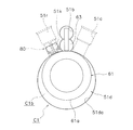
図3はシリンダ51の構成を模式的に示す平面図である。シリンダ51は、軸方向が上下方向に延びるようにケーシング20の内部に配置される。シリンダ51は、上下両端が開口しており、内部に円柱状のシリンダ孔51d(円筒形状のシリンダ51の中空部)が形成される。シリンダ孔51dには、図4に示すように、ピストン61が収納される。
図3はシリンダ51の構成を模式的に示す平面図である。シリンダ51は、軸方向が上下方向に延びるようにケーシング20の内部に配置される。シリンダ51は、上下両端が開口しており、内部に円柱状のシリンダ孔51d(円筒形状のシリンダ51の中空部)が形成される。シリンダ孔51dには、図4に示すように、ピストン61が収納される。
シリンダ51の、シリンダ孔51dの外周側には、ブッシュ63が回転自在に挿入されたブッシュ保持孔51a、および、ブッシュ保持孔51aに連通する給油孔51bが形成される。また、シリンダ51には、シリンダ孔51dに連通する吸入通路51cが形成される。
ブッシュ保持孔51aおよび給油孔51bの内部には、ブレード62が配置される。ブレード62は、後述するピストン61の偏心回転に応じて、ブッシュ保持孔51aに配置されたブッシュ63により揺動可能に支持される。給油孔51bは、後述する、シリンダ51の下方の開口を閉塞するリアヘッド53に形成された給油連通孔53bと、上端が給油連通孔53bに接続され下端が油溜空間25内に配置されるオイルピックアップ54の内部に形成された流路54aと、を介して油溜空間25に連通する。油溜空間25の冷凍機油Lは、圧力差により給油孔51bまで吸い上げられ、摺動部の潤滑に利用される。
吸入通路51cは、シリンダ51の外周面からシリンダ孔51dまで、径方向に沿ってシリンダ51を貫通して形成される。これにより、吸入通路51c、シリンダ孔51dに連通する。吸入通路51cには、吸入管23の先端部が挿入される。そして、吸入管23から吸入通路51cを介してシリンダ孔51dの内部に形成される圧縮室C1へと冷媒が導かれる。
また、シリンダ51には、圧縮室C1に連通するインジェクション通路51rと、後述する弁組立体80を格納する格納部51kとが形成される。ここでは、インジェクション通路51rは、シリンダ51を水平方向に延びるように形成される。このインジェクション通路51rには、インジェクション配管90が挿入されて固定される。また、格納部51kは、インジェクション配管90と圧縮室C1との間の空間であり、インジェクション配管90から流入する中間圧(高圧と低圧との中間の圧力)の冷媒が格納部51kを通過して圧縮室C1に供給される。
(3-4-2)フロントヘッド
フロントヘッド52は、シリンダ51の上方に配置される。フロントヘッド52は、シリンダ51の上方の開口を塞ぐ。すなわち、フロントヘッド52は、円筒形状のシリンダ51のシリンダ孔51dの上方の開口を塞ぐ。そして、フロントヘッド52は、シリンダ51の内周面51da(シリンダ孔51dを囲む面)と、シリンダ孔51d内に配置されるピストン61の外周面61aとの間に形成される圧縮室C1の天面を形成する。また、フロントヘッド52には、圧縮室C1に連通する図示しない吐出通路が形成されており、圧縮室C1で圧縮された冷媒は、吐出通路を通って圧縮室C1から流出する。
フロントヘッド52は、シリンダ51の上方に配置される。フロントヘッド52は、シリンダ51の上方の開口を塞ぐ。すなわち、フロントヘッド52は、円筒形状のシリンダ51のシリンダ孔51dの上方の開口を塞ぐ。そして、フロントヘッド52は、シリンダ51の内周面51da(シリンダ孔51dを囲む面)と、シリンダ孔51d内に配置されるピストン61の外周面61aとの間に形成される圧縮室C1の天面を形成する。また、フロントヘッド52には、圧縮室C1に連通する図示しない吐出通路が形成されており、圧縮室C1で圧縮された冷媒は、吐出通路を通って圧縮室C1から流出する。
フロントヘッド52の上部には、駆動軸40を回転自在に支持する円筒状の上部軸受部52aが形成される。
(3-4-3)リアヘッド
リアヘッド53は、図2に示すように、シリンダ51の下方に配置される。リアヘッド53は、シリンダ51の下方の開口を閉塞する。言い換えれば、円筒形状のシリンダ51のシリンダ孔51dの下方の開口を塞ぐ。そして、リアヘッド53は、シリンダ51の内周面51daと、シリンダ孔51d内に配置されるピストン61の外周面61aとの間に形成される圧縮室C1の底面を形成する。
リアヘッド53は、図2に示すように、シリンダ51の下方に配置される。リアヘッド53は、シリンダ51の下方の開口を閉塞する。言い換えれば、円筒形状のシリンダ51のシリンダ孔51dの下方の開口を塞ぐ。そして、リアヘッド53は、シリンダ51の内周面51daと、シリンダ孔51d内に配置されるピストン61の外周面61aとの間に形成される圧縮室C1の底面を形成する。
リアヘッド53の下部には、駆動軸40を回転自在に支持する円筒状の下部軸受部53aが形成される。
リアヘッド53には、シリンダ51の給油孔51bに囲まれた空間と連通する給油連通孔53bが形成される。給油連通孔53bは、上下方向にリアヘッド53を貫通する。給油連通孔53bは、リアヘッド53の下部に取り付けられたオイルピックアップ54の内部に形成されている流路54aと連通する。オイルピックアップ54の下端は油溜空間25に配置される。油溜空間25の冷凍機油Lは、圧力差により、流路54aおよび給油連通孔53bを経て、給油孔51bの内部に供給される。
(3-4-4)ピストン
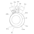
ピストン61は、図4に示すように、円筒状に形成された部材である。ピストン61は、ブレード62と一体に形成される。ピストン61の内部には、駆動軸40の偏心部41が嵌め込まれる。
ピストン61は、図4に示すように、円筒状に形成された部材である。ピストン61は、ブレード62と一体に形成される。ピストン61の内部には、駆動軸40の偏心部41が嵌め込まれる。
ピストン61は、シリンダ51、フロントヘッド52、およびリアヘッド53と共に、圧縮室C1を形成する。圧縮室C1は、ピストン61の外周面61aと、シリンダ51の内周面51daと、フロントヘッド52の下面と、リアヘッド53の上面と、により囲まれた空間である。駆動軸40が回転すると、ピストン61が、シリンダ孔51d内で、シリンダ51の内周面51daに沿って偏心回転運動を行う(シリンダ51のシリンダ孔51dに沿って公転する)。そして、ピストン61が、シリンダ51の吸入通路51cを介して圧縮室C1に吸入される冷媒を圧縮する。
(3-4-5)ブレード
ブレード62は、圧縮室C1を、低圧室C1aと高圧室C1bとに区画する部材である。ブレード62は、ピストン61と一体に形成された板状の部材である。ブレード62は、円筒状のピストン61の外周面61aから、径方向外側に向かって延びるように形成される。
ブレード62は、圧縮室C1を、低圧室C1aと高圧室C1bとに区画する部材である。ブレード62は、ピストン61と一体に形成された板状の部材である。ブレード62は、円筒状のピストン61の外周面61aから、径方向外側に向かって延びるように形成される。
ブレード62は、シリンダ51のブッシュ保持孔51aに配置された一対のブッシュ63により挟みこまれ、ブッシュ63により揺動可能に支持される。そして、駆動軸40が回転すると、ブッシュ63により支持されるブレード62は揺動し、ピストン61の偏心回転に応じてブッシュ保持孔51aおよび給油孔51bに出入りする。なお、ブレード62により、ピストン61の自転は規制される。
(3-4-6)ブッシュ
圧縮機構50は、1対のブッシュ63を有する。ブッシュ63は、ブッシュ保持孔51aに配置される。各ブッシュ63は、半円筒形状(円柱を軸方向に沿って2つに分割した形状)の部材である。1対のブッシュ63は、その間でブレード62を挟み、ブレード62を揺動可能に支持する。
圧縮機構50は、1対のブッシュ63を有する。ブッシュ63は、ブッシュ保持孔51aに配置される。各ブッシュ63は、半円筒形状(円柱を軸方向に沿って2つに分割した形状)の部材である。1対のブッシュ63は、その間でブレード62を挟み、ブレード62を揺動可能に支持する。
(3-4-7)弁組立体
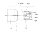
弁組立体80は、圧縮室C1とインジェクション配管90との間に設けられ、逆止弁として機能するものである。具体的には、弁組立体80は、図5に示すように、開口形成部材81と、弁本体82と、バネ部材83と、バネ受部材(可動部材)84とを有する。
弁組立体80は、圧縮室C1とインジェクション配管90との間に設けられ、逆止弁として機能するものである。具体的には、弁組立体80は、図5に示すように、開口形成部材81と、弁本体82と、バネ部材83と、バネ受部材(可動部材)84とを有する。
なお、本実施形態では、図6に示すように、開口81aを流出する中間圧冷媒の流出方向d1と、インジェクション通路51rから圧縮室C1に流出する中間圧冷媒の流出方向d2とが略水平となるように、弁組立体80が格納部51kに格納される。
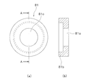
図7は開口形成部材81の構成を示す模式図である。図7(a)は開口形成部材81の平面図を模式的に示しており、図7(b)は図7(a)のA-A断面図を模式的に示している。開口形成部材81は、図7(a)に示すように、開口81aが形成される平板状の部分を有する。開口81aは、後述する弁本体82の平板部82aと密着することで閉塞される。また、開口形成部材81は、図7(b)に示すように、バネ部材83の周囲の一部を囲って保持する保持部81bを有する。保持部81bは、後述するバネ受部材84に係合してバネ受部材84の動きを規制する。この開口形成部材81は外周が格納部51kに密着しているので、開口81aが閉塞されたときには、圧縮室C1からの冷媒の逆流が阻止される。
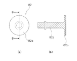
図8は弁本体82の構成を示す模式図である。図8(a)は弁本体82の平面図を模式的に示しており、図8(b)は図8(a)のB-B断面図を示している。弁本体82は、図8(a)に示すように、平板状の平板部82aを有する。また、弁本体82は、図8(b)に示すように、平板部82aの中心軸上に棒状の弁軸部82bが設けられる。弁軸部82bは、開口形成部材81の開口81aを貫通してバネ受部材84と連結する。これにより、バネ受部材84の動きに応じて弁本体82も移動する。具体的に、弁本体82は、インジェクション配管90から供給される中間圧冷媒の圧力と圧縮室C1内の圧縮途中の冷媒の圧力との差に応じて移動する。そして、弁本体82は、圧縮室C1側からインジェクション配管90側に移動したときに、開口形成部材81の開口81aを閉塞する。
バネ部材83は、開口81aに対してインジェクション配管90側に配置され、弁本体82に対してインジェクション配管90側の向きに力を加えるものである。ここでは、バネ部材83は、一例として、押しバネが採用される。バネ部材83は、図5に示すように、弁軸部82bを囲うようにして、開口形成部材81の保持部81b及びバネ受部材84の保持部84cの内側に設置される。
図9はバネ受部材84の構成を示す模式図である。図9(a)はバネ受部材84の平面図を模式的に示しており、図9(b)は図9(a)のC-C断面図を示している。バネ受部材84は、図9(a)に示すように、平板状の底面部84dを有する。底面部84dは、バネ部材83の押しバネと接触する部分であり、押しバネ荷重が加えられる。また、底面部84dは、流路開口84a及び連結孔84bを有する。連結孔84bには、弁本体の弁軸部82bが挿入されて固定される。すなわち、バネ受部材84は、開口81aに対してインジェクション配管90側で、弁本体82と連結する。このような構造により、バネ受部材84で受けたバネ荷重が弁本体82に伝達される。また、バネ受部材84は、図9(b)に示すように、断面がコの字型の円筒形状であり、保持部84cが底面部84dの円周部分に形成される。
なお、上記説明では、弁本体82の弁軸部82bは、図8に示すような棒状であったが、図10に示すようなバケツ状のものであってもよい。図10に示す形態では、弁軸部82bの一部がバネ受部材84として機能している。その他、弁組立体80の各構成部材は、本発明の効果を実現できる任意の形状を採用可能である。
(4)運転動作
上述したロータリ圧縮機100は以下のように動作する。
上述したロータリ圧縮機100は以下のように動作する。
まず、モータ30が起動する。これにより、ロータ32がステータ31に対して回転し、ロータ32に固定された駆動軸40が回転する。駆動軸40が回転すると、駆動軸40の偏心部41が偏心回転する。そして、この偏心部41が内部に嵌め込まれたピストン61が、シリンダ51のシリンダ孔51dに沿って公転する。この際、ピストン61の自転は、ピストン61と一体に形成されたブレード62によって規制される。
ピストン61は、上死点にある図11の状態から(図11では時計回りに)回転を開始する。そして、吸入通路51cから、低圧室C1aへの冷媒の吸入工程が開始される。駆動軸40の回転角が大きくなると、低圧室C1aの容積が増大し(図12~図14参照)、低圧室C1aへ吸入される冷媒量が増加する。そして、ピストン61が上死点まで回転すると、低圧室C1aにおける冷媒の閉じ込みが完了する。
続いて、図11に戻り、吸入通路51cに繋がっていた低圧室C1aが、フロントヘッド52に形成された図示しない吐出通路に繋がる高圧室C1bに移行する。そして、ピストン61の回転角度が大きくなると、高圧室C1bの容積が減少する(図12~14参照)。それに伴って高圧室C1bの圧力が上昇する。高圧室C1bの圧力が所定圧力を上回ると、吐出通路に設けられた図示しない吐出弁が開く。この後、高圧室C1bの冷媒が、吐出通路を介してケーシング20の内部空間へ吐出される。そして、圧縮された冷媒が吐出管24を介してロータリ圧縮機100の外部へと吐出される。冷媒の吐出行程は、ピストン61の回転角度が360度になるまで続く。ロータリ圧縮機100では、上述した吸入行程と吐出行程とが繰り返されて、冷媒の吸入/圧縮動作が連続的に行われる。
ここで、圧縮途中の圧縮室C1には、インジェクション通路51rを介して、中間圧冷媒がインジェクションされる。具体的には、インジェクション通路51rの方が圧縮室C1より圧力が高い場合、インジェクション通路51rから圧縮室C1に中間圧の冷媒がインジェクションされる。一方、圧縮室C1の圧力が高くなり、圧縮室C1の方がインジェクション通路51rより圧力が高くなると、インジェクション通路51rに設けられた弁組立体80が閉塞状態となり、中間圧冷媒の供給が停止される。このように、本実施形態に係るロータリ圧縮機100では、中間圧冷媒をインジェクションすることで圧縮効率を高めている。
なお、ケーシング20の内部空間は、圧縮機構50において圧縮された冷媒が吐出されるので、高圧になる。これにより、油溜空間25の高圧の冷凍機油Lが、駆動軸40の下端部に設けられた油ポンプ42および給油通路43を経て、圧縮機構50に供給される。
(5)特徴
(5-1)
以上説明したように、本実施形態では、ロータリ圧縮機100が、圧縮室C1内の低圧冷媒を圧縮して高圧冷媒にする圧縮機構50と、圧縮室C1内に中間圧冷媒を供給するためのインジェクション配管90と、圧縮室C1とインジェクション配管90との間に設けられる弁組立体80と、を備える。ここで、弁組立体80は、開口形成部材81と、弁本体82と、バネ部材83と、を有する。開口形成部材81は、開口81aを形成する。弁本体82は、インジェクション配管90から供給される冷媒の圧力と圧縮室C1内の圧縮途中の冷媒の圧力との差に応じて移動し、圧縮室C1側からインジェクション配管90側に移動したときに、開口81aを塞ぐ。バネ部材83は、開口81aに対してインジェクション配管90側に配置され、弁本体82に対してインジェクション配管90側の向きに力を加える。
(5-1)
以上説明したように、本実施形態では、ロータリ圧縮機100が、圧縮室C1内の低圧冷媒を圧縮して高圧冷媒にする圧縮機構50と、圧縮室C1内に中間圧冷媒を供給するためのインジェクション配管90と、圧縮室C1とインジェクション配管90との間に設けられる弁組立体80と、を備える。ここで、弁組立体80は、開口形成部材81と、弁本体82と、バネ部材83と、を有する。開口形成部材81は、開口81aを形成する。弁本体82は、インジェクション配管90から供給される冷媒の圧力と圧縮室C1内の圧縮途中の冷媒の圧力との差に応じて移動し、圧縮室C1側からインジェクション配管90側に移動したときに、開口81aを塞ぐ。バネ部材83は、開口81aに対してインジェクション配管90側に配置され、弁本体82に対してインジェクション配管90側の向きに力を加える。
したがって、本実施形態に係るロータリ圧縮機100では、弁組立体80が、開口81aを塞ぐのに、開口81aに対してインジェクション配管90側に配置されるバネ部材83を用いているので、開口81aと圧縮室C1との間のインジェクション通路51rの死容積を小さくできる。これにより、インジェクション通路51rにおける開口部と圧縮室との間の空間に、圧縮された冷媒が溜まるのを低減できる。この結果、圧縮された冷媒の低圧側圧縮室への逆流を低減でき、圧縮効率の高いロータリ圧縮機100を提供できる。
補足すると、一般的な逆止弁構造の弁組立体では、図15に示されるように、バネ部材83gが、開口81aに対して圧縮室C1側に配置される。そのため、死容積Vdが大きくなる。これに対し、本実施形態に係る弁組立体80は、図16に示されるように、バネ部材83が、開口81aに対してインジェクション配管90側に配置される。そのため、死容積Vdを小さくできる。結果として、圧縮された冷媒の低圧側圧縮室への逆流を低減でき、圧縮効率の高い圧縮機を提供できる。
(5-2)
また、本実施形態に係る弁組立体80は、開口81aに対してインジェクション配管90側に、弁本体82と連結するバネ受部材84(可動部)をさらに備える。また、バネ部材83は、押しバネである。そして、バネ受部材84がバネ部材83により押しバネ荷重を受ける。このように、本実施形態では、押しバネを用いて弁本体を動かすことができる弁組立体80を提供できる。
また、本実施形態に係る弁組立体80は、開口81aに対してインジェクション配管90側に、弁本体82と連結するバネ受部材84(可動部)をさらに備える。また、バネ部材83は、押しバネである。そして、バネ受部材84がバネ部材83により押しバネ荷重を受ける。このように、本実施形態では、押しバネを用いて弁本体を動かすことができる弁組立体80を提供できる。
(5-3)
また、本実施形態に係る弁組立体80は、開口形成部材81が、バネ部材83の周囲を囲って保持する保持部81bをさらに有する。これにより、バネ部材83が開口形成部材81で保持されるので、バネ部材83の離脱を阻止するとともに、一体構成の弁組立体80を提供できる。
また、本実施形態に係る弁組立体80は、開口形成部材81が、バネ部材83の周囲を囲って保持する保持部81bをさらに有する。これにより、バネ部材83が開口形成部材81で保持されるので、バネ部材83の離脱を阻止するとともに、一体構成の弁組立体80を提供できる。
(5-4)
また、本実施形態に係る弁組立体80は、開口形成部材81の保持部81bが、バネ受部材84(可動部)に係合してバネ受部材84の動きを規制する。ここで、バネ受部材84は弁軸部82bと連結している。したがって、このような構成により、バネ部材83により弁本体82が必要以上に移動するのを回避できる。具体的には、弁本体がインジェクション配管90から圧縮室C1に飛び出るのを回避できる。
また、本実施形態に係る弁組立体80は、開口形成部材81の保持部81bが、バネ受部材84(可動部)に係合してバネ受部材84の動きを規制する。ここで、バネ受部材84は弁軸部82bと連結している。したがって、このような構成により、バネ部材83により弁本体82が必要以上に移動するのを回避できる。具体的には、弁本体がインジェクション配管90から圧縮室C1に飛び出るのを回避できる。
(5-5)
また、本実施形態に係る弁組立体80は、バネ受部材84(可動部)が、流路開口84aを有する。これにより、インジェクション配管90から流入する中間圧冷媒を、弁組立体80の内部を通過させて圧縮室C1に供給できる。
また、本実施形態に係る弁組立体80は、バネ受部材84(可動部)が、流路開口84aを有する。これにより、インジェクション配管90から流入する中間圧冷媒を、弁組立体80の内部を通過させて圧縮室C1に供給できる。
(5-6)
また、本実施形態では圧縮機構50が、圧縮室C1に中間圧冷媒を流出するインジェクション通路51rと、弁組立体80を格納する格納部51kと、を有する。そして、格納部51kが、開口形成部材81の開口81aを流出する中間圧冷媒の流出方向d1と、インジェクション通路51rから圧縮室C1に流出する中間圧冷媒の流出方向d2とが略水平となるように、弁組立体80を格納する。
また、本実施形態では圧縮機構50が、圧縮室C1に中間圧冷媒を流出するインジェクション通路51rと、弁組立体80を格納する格納部51kと、を有する。そして、格納部51kが、開口形成部材81の開口81aを流出する中間圧冷媒の流出方向d1と、インジェクション通路51rから圧縮室C1に流出する中間圧冷媒の流出方向d2とが略水平となるように、弁組立体80を格納する。
このようなロータリ圧縮機100であれば、インジェクション配管90から圧縮室C1まで直線的に中間圧冷媒が流入するので、開口81aが開いたときに速やかに中間圧冷媒を供給できる。また、上記圧縮機構50は、シリンダ51の径方向に貫通穴を形成することにより、インジェクション通路51rを設けることができる。そして、この貫通穴に弁組立体80を嵌め込むだけで、上記構成のロータリ圧縮機100を製造できる。したがって、このような構成であれば圧縮効率の高いロータリ圧縮機100を容易に製造できる。
(6)変形例
以下に、本実施形態の変形例を示す。なお、各変形例は、矛盾しない範囲で、他の変形例と適宜組み合わされてもよい。
以下に、本実施形態の変形例を示す。なお、各変形例は、矛盾しない範囲で、他の変形例と適宜組み合わされてもよい。
(6-1)変形例1A
本実施形態に係るロータリ圧縮機100は、図17に示すように、弁組立体80を格納する格納部51kが、開口形成部材81の開口81aを流出する中間圧冷媒の流出方向d1と、インジェクション通路51rから圧縮室C1に流出する中間圧冷媒の流出方向d2とが略垂直となるように、弁組立体を格納するものであってもよい。
本実施形態に係るロータリ圧縮機100は、図17に示すように、弁組立体80を格納する格納部51kが、開口形成部材81の開口81aを流出する中間圧冷媒の流出方向d1と、インジェクション通路51rから圧縮室C1に流出する中間圧冷媒の流出方向d2とが略垂直となるように、弁組立体を格納するものであってもよい。
このようなロータリ圧縮機100であれば、インジェクション配管90から圧縮室C1まで曲折して中間圧冷媒が流入するので、圧縮室C1の圧力変化に対して緩やかに開口81aを開くことができる。これにより、中間圧冷媒が吸入管23に逆流することを抑制できる。結果として、圧縮効率の高いロータリ圧縮機100を提供できる。また、開口形成部材とシリンダを一体部材化することができ、部品点数を削減できる。
(6-2)変形例1B
上記実施形態では、バネ部材83が押しバネであったが、本実施形態に係るバネ部材は、これに限定されるものではない。例えば、図18に示すように、バネ部材83が、開口81aに対してインジェクション配管90側から、弁本体82に連結する引きバネであってもよい。このような構成であっても、インジェクション配管90と圧縮室C1との距離を短くすることができる。そのため、死容積Vdを減少することができ、圧縮効率の高いロータリ圧縮機100を提供できる。
上記実施形態では、バネ部材83が押しバネであったが、本実施形態に係るバネ部材は、これに限定されるものではない。例えば、図18に示すように、バネ部材83が、開口81aに対してインジェクション配管90側から、弁本体82に連結する引きバネであってもよい。このような構成であっても、インジェクション配管90と圧縮室C1との距離を短くすることができる。そのため、死容積Vdを減少することができ、圧縮効率の高いロータリ圧縮機100を提供できる。
(6-3)変形例1C
上記実施形態では、シリンダ51にインジェクション配管90が連結されているが、本実施形態に係る圧縮機は、これに限定されるものではない。フロントヘッド52又は/及びリアヘッド53にインジェクション配管90が連結されるものでもよい。この場合は、フロントヘッド52又は/及びリアヘッド53に、圧縮室C1まで連通するインジェクション通路51rが形成される。
上記実施形態では、シリンダ51にインジェクション配管90が連結されているが、本実施形態に係る圧縮機は、これに限定されるものではない。フロントヘッド52又は/及びリアヘッド53にインジェクション配管90が連結されるものでもよい。この場合は、フロントヘッド52又は/及びリアヘッド53に、圧縮室C1まで連通するインジェクション通路51rが形成される。
(6-4)変形例1D
上記実施形態では、ロータリ圧縮機100は1シリンダ型のロータリ圧縮機であるが、本実施形態に係る圧縮機は、これに限定されるものではない。ロータリ圧縮機は、複数シリンダ型(例えば2シリンダ側)のロータリ圧縮機であってもよい。
上記実施形態では、ロータリ圧縮機100は1シリンダ型のロータリ圧縮機であるが、本実施形態に係る圧縮機は、これに限定されるものではない。ロータリ圧縮機は、複数シリンダ型(例えば2シリンダ側)のロータリ圧縮機であってもよい。
(6-5)変形例1E
上記実施形態では、圧縮機は1シリンダ型のロータリ圧縮機であるが、本実施形態に係る圧縮機は、これに限定されるものではない。すなわち、本実施形態に係る弁組立体80が搭載可能なものであれば、任意の圧縮機であってよい。例えば、スクロール圧縮機においても、本実施形態に係る弁組立体80を搭載することが可能である。
上記実施形態では、圧縮機は1シリンダ型のロータリ圧縮機であるが、本実施形態に係る圧縮機は、これに限定されるものではない。すなわち、本実施形態に係る弁組立体80が搭載可能なものであれば、任意の圧縮機であってよい。例えば、スクロール圧縮機においても、本実施形態に係る弁組立体80を搭載することが可能である。
<第2実施形態>
本発明の第2実施形態に係る圧縮機200を、図面を参照しながら説明する。以下、既に説明した部分と同一の部分には略同一の符号を付し、重複した説明を省略する。
本発明の第2実施形態に係る圧縮機200を、図面を参照しながら説明する。以下、既に説明した部分と同一の部分には略同一の符号を付し、重複した説明を省略する。
(7)ロータリ圧縮機が使用される空気調和装置の概要
図19は本発明の第2実施形態に係るロータリ圧縮機200が使用される空気調和装置1Aの概要図である。第2実施形態においても、第1実施形態と同様の冷媒回路が実現される。
図19は本発明の第2実施形態に係るロータリ圧縮機200が使用される空気調和装置1Aの概要図である。第2実施形態においても、第1実施形態と同様の冷媒回路が実現される。
(8)ロータリ圧縮機の全体構成
図20は、第2実施形態に係るロータリ圧縮機200の模式的に示した縦断面図である。図21は、図20のXXI-XXI矢視におけるフロントシリンダ151部分の概略断面図である。図22は、図20のXXII-XXII矢視におけるリアシリンダ153部分の概略断面図である。
図20は、第2実施形態に係るロータリ圧縮機200の模式的に示した縦断面図である。図21は、図20のXXI-XXI矢視におけるフロントシリンダ151部分の概略断面図である。図22は、図20のXXII-XXII矢視におけるリアシリンダ153部分の概略断面図である。
なお、以下の説明において、特記が無い場合、図20中の矢印Uの方向を上方向とする。また、図20では中心から右側と左側とで異なる方向の断面図を示している。すなわち、図20において、弁組立体280及びインジェクション配管90が吸入管23に対向する位置に示されているが、実際には、弁組立体280及びインジェクション配管90は、中間圧冷媒のインジェクションの効率が最適化される位置に配置される。
ここでは、ロータリ圧縮機200は、2シリンダ型のロータリ圧縮機である。ロータリ圧縮機200は、ケーシング120と、モータ130と、駆動軸140と、圧縮機構150と、を主に備える。ケーシング120には、モータ130と、駆動軸140と、圧縮機構150とが収容される。ケーシング120内には、モータ130がケーシング120の上下方向における中央部付近に配置されており、その下方に圧縮機構150が配置される。
ロータリ圧縮機200は、吸入管23から低圧冷媒を吸入して圧縮し、高圧冷媒を吐出管24から吐出する機器である。また、ロータリ圧縮機200には、インジェクション配管90から中間圧冷媒が供給される。ロータリ圧縮機100の冷媒としては、例えばR32が使用されるが、これに限定されるものではない。
(9)詳細構成
(9-1)ケーシング
ロータリ圧縮機200のケーシング120は、図20のように、上下が開口した円筒形状の円筒部材121と、円筒部材121の上方に設けられた上蓋122aと、円筒部材121の下方に設けられた下蓋122bと、を有する。
(9-1)ケーシング
ロータリ圧縮機200のケーシング120は、図20のように、上下が開口した円筒形状の円筒部材121と、円筒部材121の上方に設けられた上蓋122aと、円筒部材121の下方に設けられた下蓋122bと、を有する。
円筒部材121の下部には、円筒部材121の下部側面を貫通して、2本の吸入管23が設けられる。ケーシング120の上部には、圧縮後の冷媒を吐出する吐出管24が、上蓋122aを貫通して設けられる。
ケーシング120内には、主に、モータ130と、モータ130の下方に配置されるロータリ圧縮機構150と、モータ130とロータリ圧縮機構150とを連結する駆動軸140と、駆動軸140を軸支する上部軸受部160及び下部軸受部170と、が収容される。駆動軸140は、円筒部材121の中心線に沿って、上下方向に延びるように配置される。
また、ケーシング120の底部には、図20に示される、冷凍機油Lを貯留する油溜空間125が形成される。冷凍機油Lは、ロータリ圧縮機構150や、上部軸受部160及び下部軸受部170等の潤滑に用いられる。
なお、本実施形態に係るロータリ圧縮機200は、いわゆる高圧ドーム型の圧縮機である。油溜空間125は、後述するフロントシリンダ151の高圧側の圧縮室S1b及びリアシリンダ153の高圧側の圧縮室S2bに、高圧空間S3を介して連通する。
(9-2)モータ
モータ130は、下方に配置されるロータリ圧縮機構150を駆動するために設けられる。モータ130は、低速から高速まで、幅広い速度領域で運転される。
モータ130は、下方に配置されるロータリ圧縮機構150を駆動するために設けられる。モータ130は、低速から高速まで、幅広い速度領域で運転される。
モータ130は、ステータ131とロータ132とを含む。ステータ131は、環状の部材であり、ケーシング120の円筒部材121の内壁面に固定される。ロータ132は、ステータ131の内部空間に、ステータ131とエアギャップ空間Gを介して回転自在に配置される。ロータ132の中央部には、上下方向に延びる駆動軸140の主軸141の上部が固定され、ロータ132と駆動軸140とが連結される。モータ130は、ステータ131とロータ132との間に発生する磁力によりロータ132を回転させ、駆動軸140を介して、ロータリ圧縮機構150を駆動する。
(9-3)駆動軸
駆動軸140は、ケーシング120の円筒部材121の中心軸に沿って延びる円柱状の主軸141と、主軸141に対して偏心している偏心部142とを有する。また、駆動軸140には、油溜空間125に溜められた油Lを、ロータリ圧縮機構150、上部軸受部160及び下部軸受部170に供給するための給油経路180が形成される。
駆動軸140は、ケーシング120の円筒部材121の中心軸に沿って延びる円柱状の主軸141と、主軸141に対して偏心している偏心部142とを有する。また、駆動軸140には、油溜空間125に溜められた油Lを、ロータリ圧縮機構150、上部軸受部160及び下部軸受部170に供給するための給油経路180が形成される。
偏心部142は、図20に示されるように、第1偏心部142aと、第1偏心部142aと180°位相をずらして偏心された第2偏心部142bとを有する。
第1偏心部142aは、図21に示されるように、後述するピストン本体部152aの内部に回転自在に嵌合する。つまり、駆動軸140は、第1偏心部142aを介してピストン152に連結される。第1偏心部142aには、ピストン本体部152aの内面と接触する第1接触面142aaが形成される。
第2偏心部142bは、図22に示されるように、後述するピストン本体部154aの内部に回転自在に嵌合する。つまり、駆動軸140は、第2偏心部142bを介してピストン154に連結される。第2偏心部142bには、ピストン本体部154aの内面と接触する第2接触面142baが形成される。
給油経路180は、吸込部181と、給油主経路182と、給油副経路183と、を有する。吸込部181は、油溜空間125内に下端が配置される中空の部材である。給油主経路182は、吸込部181を介して油溜空間125と連通し、ケーシング120の円筒部材121の中心軸に沿って駆動軸140の内部に形成される。給油副経路183は、給油主経路182から分岐して形成される。
(9-4)ロータリ圧縮機構
ロータリ圧縮機構150は、2つのシリンダを有する2シリンダ型の圧縮機構である。このロータリ圧縮機構150は、吸入管23から吸入された冷媒を圧縮して吐出する。
ロータリ圧縮機構150は、2つのシリンダを有する2シリンダ型の圧縮機構である。このロータリ圧縮機構150は、吸入管23から吸入された冷媒を圧縮して吐出する。
ロータリ圧縮機構150は、図20に示されるように、フロントシリンダ151、ピストン152、リアシリンダ153、ピストン154、ミドルプレート155、フロントヘッド156、リアヘッド157、フロントマフラ158、及びリアマフラ159を主に有する。リアシリンダ153及びピストン154は、フロントシリンダ151の下方に配置される。ミドルプレート155は、フロントシリンダ151とリアシリンダ153との間に配置される。フロントヘッド156及びリアヘッド157は、フロントシリンダ151及びリアシリンダ153を上下から挟むように設けられる。フロントマフラ158は、フロントヘッド156の上方に配置される。リアマフラ159は、リアヘッド157の下方に配置される。
(9-4-1)フロントシリンダ
フロントシリンダ151には、図21に示されるように、シリンダ空間(圧縮室)S1、吸入孔151a、ブッシュ収容孔151b、及びブレード収容孔151cが形成される。
フロントシリンダ151には、図21に示されるように、シリンダ空間(圧縮室)S1、吸入孔151a、ブッシュ収容孔151b、及びブレード収容孔151cが形成される。
シリンダ空間S1は、フロントシリンダ151、フロントヘッド156及びミドルプレート155により周囲を囲まれる空間である。シリンダ空間S1内には、ピストン152が配置され、ピストン152により、吸入孔151aが連通する低圧側の圧縮室S1aと、後述するフロントヘッド156に形成された吐出孔156aが連通する高圧側の圧縮室S1bとが区画される。
吸入孔151aは、フロントシリンダ151を径方向に貫通し、吸入管23と低圧側の圧縮室S1aとを連通する。
ブッシュ収容孔151bは、フロントシリンダ151を板厚方向に貫通する円柱状の孔である。ブッシュ収容孔151bには、一対の半円形状のブッシュ1511が、後述するピストン152のブレード152bを挟み込むように収容される。ブッシュ1511は、フロントシリンダ151に対して揺動可能に取り付けられる。
ブレード収容孔151cはフロントシリンダ151を板圧方向に貫通する円柱状の孔であり、ブッシュ収容孔151bと連通する。
(9-4-2)ピストン
ピストン152は、フロントシリンダ151内に配置され、フロントシリンダ151のシリンダ空間S1内に低圧側及び高圧側の圧縮室S1a,S1bを形成する。ピストン152が、偏心回転運動することで、低圧側の圧縮室S1aに吸引された冷媒が、高圧側の圧縮室S1bで圧縮される。
ピストン152は、フロントシリンダ151内に配置され、フロントシリンダ151のシリンダ空間S1内に低圧側及び高圧側の圧縮室S1a,S1bを形成する。ピストン152が、偏心回転運動することで、低圧側の圧縮室S1aに吸引された冷媒が、高圧側の圧縮室S1bで圧縮される。
ピストン152は、図21に示されるように、環状のピストン本体部152aと、ピストン本体部152aから径方向外向きに延びる平板状のブレード152bと、を有する。
ピストン本体部152aには、駆動軸140の第1偏心部142aが挿嵌される。駆動軸140が回転すると、ピストン本体部152aがフロントシリンダ151の内周面と摺接しながら偏心回転運動を行い、ブレード152bが揺動すると同時に長手方向に沿って進退運動を行う。この時、吸入管23から低圧側の圧縮室S1aに吸入された冷媒は、ピストン本体部152aにより高圧側の圧縮室S1bにおいて圧縮され、後述するフロントヘッド156に形成された吐出孔156aからマフラ空間S4に吐出される。
(9-4-3)リアシリンダ
リアシリンダ153には、図22に示されるように、シリンダ空間(圧縮室)S2、吸入孔153a、ブッシュ収容孔153b、及びブレード収容孔153cが形成される。
リアシリンダ153には、図22に示されるように、シリンダ空間(圧縮室)S2、吸入孔153a、ブッシュ収容孔153b、及びブレード収容孔153cが形成される。
シリンダ空間S2は、リアシリンダ153、リアヘッド157及びミドルプレート155により周囲を囲まれる空間である。シリンダ空間S2内には、ピストン154が配置され、ピストン154により、吸入孔153aが連通する低圧側の圧縮室S2aと、後述するリアヘッド157に形成された吐出孔157aが連通する高圧側の圧縮室S2bとが区画される。
吸入孔153aは、リアシリンダ153を径方向に貫通し、吸入管23と低圧側の圧縮室S2aとを連通する。
ブッシュ収容孔153bは、リアシリンダ153を板圧方向に貫通する円柱状の孔である。ブッシュ収容孔153bには、一対の半円形状のブッシュ1531が、後述するピストン154のブレード154bを挟み込むように収容される。ブッシュ1531は、リアシリンダ153に対して揺動可能に取り付けられる。
ブレード収容孔153cはリアシリンダ153を板圧方向に貫通する円柱状の孔であり、ブッシュ収容孔153bと連通する。
(9-4-4)ピストン
ピストン154は、リアシリンダ153内に配置され、リアシリンダ153のシリンダ空間S2内に低圧側及び高圧側の圧縮室S2a,S2bを形成する。ピストン154が、偏心回転運動することで、低圧側の圧縮室S2aに吸引された冷媒が、高圧側の圧縮室S2bで圧縮される。
ピストン154は、リアシリンダ153内に配置され、リアシリンダ153のシリンダ空間S2内に低圧側及び高圧側の圧縮室S2a,S2bを形成する。ピストン154が、偏心回転運動することで、低圧側の圧縮室S2aに吸引された冷媒が、高圧側の圧縮室S2bで圧縮される。
ピストン154は、図22に示されるように、環状のピストン本体部154aと、ピストン本体部154aから径方向外向きに延びる平板状のブレード154bと、を有する。
ピストン本体部154aには、駆動軸140の第2偏心部142bが挿嵌される。駆動軸140が回転すると、ピストン本体部154aがリアシリンダ153の内周面と摺接しながら偏心回転運動を行い、ブレード154bが揺動すると同時に長手方向に沿って進退運動を行う。この時、吸入管23から低圧側の圧縮室S2aに吸入された冷媒は、ピストン本体部154aにより高圧側の圧縮室S2bにおいて圧縮され、後述するリアヘッド157に形成された吐出孔157aからマフラ空間S5に吐出される。
(9-4-5)ミドルプレート
ミドルプレート155は、図20のように、フロントシリンダ151とリアシリンダ153との間に配置される。ミドルプレート155は、フロントシリンダ151のシリンダ空間S1の下方の開口を閉塞し、リアシリンダ153のシリンダ空間S2の上方の開口を閉塞する。
ミドルプレート155は、図20のように、フロントシリンダ151とリアシリンダ153との間に配置される。ミドルプレート155は、フロントシリンダ151のシリンダ空間S1の下方の開口を閉塞し、リアシリンダ153のシリンダ空間S2の上方の開口を閉塞する。
(9-4-6)フロントヘッド
フロントヘッド156は、フロントシリンダ151の上方に配置される。フロントヘッド156は、フロントシリンダ151のシリンダ空間S1の上方の開口を閉塞する。また、フロントヘッド156には、上下方向に延びる駆動軸140を軸支する上部軸受部160が一体に形成される。上部軸受部160については後述する。
フロントヘッド156は、フロントシリンダ151の上方に配置される。フロントヘッド156は、フロントシリンダ151のシリンダ空間S1の上方の開口を閉塞する。また、フロントヘッド156には、上下方向に延びる駆動軸140を軸支する上部軸受部160が一体に形成される。上部軸受部160については後述する。
フロントヘッド156には、ピストン152の偏心回転駆動によって圧縮された高圧側の圧縮室S1b内の冷媒を、後述するマフラ空間S4に吐出させるための吐出孔156aが形成される(図21参照)。吐出孔156aは、フロントヘッド156を上下方向に貫通するように形成される。吐出孔156aの上方には、図示しない吐出弁が配置される。
(9-4-7)リアヘッド
リアヘッド157は、リアシリンダ153の下方に配置される。リアヘッド157は、リアシリンダ153のシリンダ空間S2の下方の開口を閉塞する。また、リアヘッド157には、上下方向に延びる駆動軸140を軸支する下部軸受部170が一体に形成される。下部軸受部170については後述する。
リアヘッド157は、リアシリンダ153の下方に配置される。リアヘッド157は、リアシリンダ153のシリンダ空間S2の下方の開口を閉塞する。また、リアヘッド157には、上下方向に延びる駆動軸140を軸支する下部軸受部170が一体に形成される。下部軸受部170については後述する。
リアヘッド157には、ピストン154の偏心回転駆動によって圧縮された高圧側の圧縮室S2b内の冷媒を、後述するマフラ空間S5に吐出させるための吐出孔157aが形成される(図22参照)。吐出孔157aは、リアヘッド157を上下方向に貫通するように形成される。吐出孔157aの下方には、図示しない吐出弁が配置される。
(9-4-8)フロントマフラ
フロントマフラ158は、フロントヘッド156の上方に設けられ、フロントマフラ158とフロントヘッド156との間にマフラ空間S4を形成する。マフラ空間S4が形成されることで、高圧側の圧縮室S1bからの冷媒の吐出に伴う騒音が低減される。
フロントマフラ158は、フロントヘッド156の上方に設けられ、フロントマフラ158とフロントヘッド156との間にマフラ空間S4を形成する。マフラ空間S4が形成されることで、高圧側の圧縮室S1bからの冷媒の吐出に伴う騒音が低減される。
また、フロントマフラ158には、マフラ空間S4から冷媒を吐出するため、図示しない吐出孔が形成される。マフラ空間S4内の冷媒は、図示しない吐出孔を通過して、フロントマフラ158の上方、すなわちフロントヘッド156の上方の高圧空間S3に吐出される。高圧空間S3に吐出された冷媒は、モータ130のステータ131とロータ132との間のエアギャップ空間Gを通過して、ケーシング120内を上方に移動し、吐出管24から吐出される。
(9-4-9)リアマフラ
リアマフラ159は、リアヘッド157の下方に設けられ、リアマフラ159とリアヘッド157との間にマフラ空間S5を形成する。マフラ空間S5が形成されることで、高圧側の圧縮室S2bからの冷媒の吐出に伴う騒音が低減される。
リアマフラ159は、リアヘッド157の下方に設けられ、リアマフラ159とリアヘッド157との間にマフラ空間S5を形成する。マフラ空間S5が形成されることで、高圧側の圧縮室S2bからの冷媒の吐出に伴う騒音が低減される。
マフラ空間S5の冷媒は、リアヘッド157、リアシリンダ153、ミドルプレート155、フロントシリンダ151及びフロントヘッド156を連通して形成される、図示しない連通孔を通って、マフラ空間S4に流入する。
(9-5)上部軸受部
上部軸受部160は、フロントヘッド156と一体に形成され、上下方向に延びる駆動軸140を軸支する。すなわち、上部軸受部160の中央の開口部に駆動軸40が挿嵌される。
上部軸受部160は、フロントヘッド156と一体に形成され、上下方向に延びる駆動軸140を軸支する。すなわち、上部軸受部160の中央の開口部に駆動軸40が挿嵌される。
(9-6)下部軸受部
下部軸受部170は、リアヘッド157と一体に形成され、上下方向に延びる駆動軸140を軸支する。すなわち、下部軸受部170の中央の開口部に駆動軸140が挿嵌される。
下部軸受部170は、リアヘッド157と一体に形成され、上下方向に延びる駆動軸140を軸支する。すなわち、下部軸受部170の中央の開口部に駆動軸140が挿嵌される。
(9-7)弁組立体
弁組立体280は、フロントシリンダ151及びリアシリンダ153内の圧縮室S1b,S2bとインジェクション配管90との間に設けられ、逆止弁として機能するものである。具体的には、弁組立体280は、図23,24に示すように、開口形成部材281と、弁本体282と、バネ部材283と、バネ受部材(可動部材)284と、止め部285とを有する。なお、図24は、弁組立体280の各構成部材を分解して示した模式図である。
弁組立体280は、フロントシリンダ151及びリアシリンダ153内の圧縮室S1b,S2bとインジェクション配管90との間に設けられ、逆止弁として機能するものである。具体的には、弁組立体280は、図23,24に示すように、開口形成部材281と、弁本体282と、バネ部材283と、バネ受部材(可動部材)284と、止め部285とを有する。なお、図24は、弁組立体280の各構成部材を分解して示した模式図である。
本実施形態では、弁組立体280は、図25に示すように、開口形成部材281の開口281aを流出する中間圧冷媒の流出方向d1と、インジェクション通路151r,153rから圧縮室に流出する中間圧冷媒の流出方向d2とが略水平となるように、シリンダ151,153内の格納部151k,153kに格納される。
開口形成部材281は、第1実施形態に係る開口形成部材81と同様に、開口281aが形成される平板状の部分を有する。開口281aは、後述する弁本体282の平板部282aと密着することで閉塞される。開口形成部材281は外周が格納部151kに密着しているので、開口281aが閉塞されたときには、圧縮室からの冷媒の逆流が阻止される。また、開口形成部材281は、円筒部281bを有する。円筒部281bは、後述する弁軸部282bを囲うように設けられる。さらに、円筒部281bの外側にはバネ部材283が配置される。円筒部281bは、後述するバネ受部材284に係合してバネ部材283の動きを規制する。
弁本体282は、平板状の平板部282aを有する。また、弁本体282は、平板部282aの中心軸上に棒状の弁軸部282bが設けられる。弁軸部282bは、開口形成部材281の開口281aを通過してバネ受部材284と連結する。これにより、バネ荷重が加わるバネ受部材284の動きに応じて弁本体282も移動する。具体的には、弁本体282は、インジェクション配管90から供給される中間圧冷媒の圧力と圧縮室内の圧縮途中の冷媒の圧力との差に応じて移動する。そして、弁本体282は、圧縮室側からインジェクション配管90側に移動したときに、開口形成部材281の開口281aを閉塞する。
バネ部材283は、開口281aに対してインジェクション配管90側に配置され、弁本体282に対してインジェクション配管90側の向きに力を加えるものである。ここでは、バネ部材283として、押しバネが採用される。バネ部材283は、円筒部281bを囲うように外側に配置される。
バネ受部材284は、バネ部材283の直径より大きな直径を有する平板状の部材である。バネ受部材284は、バネ部材283の押しバネと接触する部分であり、押しバネ荷重が加えられる。また、バネ受部材284は、流路開口284a及び連結孔284bを有する。連結孔284bには、弁本体の弁軸部282bが挿入されて固定される。すなわち、バネ受部材284は、開口281aに対してインジェクション配管90側で、弁本体282と連結する。このような構造により、バネ受部材284で受けたバネ荷重が弁本体282に伝達される。
止め部285は、弁軸部282bのインジェクション配管90側の端部と螺合する部材である。止め部285が弁軸部282bに固定されることで、開口形成部材281、弁本体282、バネ部材283、及びバネ受部材284が一体化される。
なお、弁組立体280の各構成部材は、本発明の効果を実現できる任意の形状を採用可能である。
(10)運転動作
上述したロータリ圧縮機200は以下のように動作する。
上述したロータリ圧縮機200は以下のように動作する。
まず、モータ130が起動する。これにより、ロータ132がステータ131に対して回転し、ロータ132に固定された駆動軸140が回転する。駆動軸140が回転すると、駆動軸140の第1偏心部142a及び第2偏心部142bに連結されるピストン152及びピストン154が駆動される。これにより、フロントシリンダ151及びリアシリンダ153内で冷媒が圧縮され、マフラ空間S4,S5に吐出される。
具体的には、駆動軸140が回転すると、フロントシリンダ151において、第1偏心部142aの第1接触面142aaが、環状のピストン本体部152aの内周面と摺接する。そして、ピストン152のブレード152bは揺動すると同時に長手方向に沿って進退運動を行い、ピストン本体部152aは偏心回転運動を行う。ピストン本体部152aの外周面は、フロントシリンダ151の内周面と摺接する。
この際、フロントシリンダ151内に、吸入孔151aと連通する低圧側の圧縮室S1aが区画され、アキュムレータ6から冷媒が吸引される。また、同時に吐出孔156aと連通する高圧側の圧縮室S1bでは冷媒が圧縮され、所定の圧力になると、吐出孔156aの上方に配置される吐出弁を押し上げて冷媒がマフラ空間S4内に吐出される。マフラ空間S4に吐出された冷媒は、フロントヘッド156の上方に形成される高圧空間S3に流入し、モータ130のステータ131とロータ132との間のエアギャップ空間Gを通過してケーシング120内を上方に移動し、吐出管24から吐出される。
同様にして、リアシリンダ153において、圧縮室S2bからマフラ空間S5に冷媒が吐出される。リアシリンダ153から吐出された冷媒は、一旦マフラ空間S4に流入する。そして、上記と同じ経路を通って吐出管24から吐出される。
ここで、圧縮途中の圧縮室S1b,S2bには、インジェクション通路151r,153rを介して、中間圧冷媒がインジェクションされる。具体的には、インジェクション通路151r,153rの方が圧縮室S1b,S2bより圧力が高い場合、インジェクション通路151r,153rから圧縮室S1b,S2bに中間圧の冷媒がインジェクションされる。一方、圧縮室S1b,S2bの圧力が高くなり、圧縮室S1b,S2bの方がインジェクション通路151rより圧力が高くなると、インジェクション通路151r,153rに設けられた弁組立体280が閉状態となり、中間圧冷媒の供給が停止される。このように、本実施形態に係るロータリ圧縮機200では、中間圧冷媒をインジェクションすることで圧縮効率を高めている。
なお、給油経路180では、フロントシリンダ51の圧縮室S1a,S1bと油溜空間125との圧力差、及び、リアシリンダ153の圧縮室S2a,S2bと油溜空間125との圧力差を利用して、冷凍機油Lが移送される。これにより、油溜空間SLの冷凍機油Lが、給油経路180を経て、ロータリ圧縮機構150に供給される。
(11)特徴
(11-1)
以上説明したように、本実施形態では、ロータリ圧縮機200が、圧縮室S1,S2内の低圧冷媒を圧縮して高圧冷媒にする圧縮機構150と、圧縮室S1,S2内に中間圧冷媒を供給するためのインジェクション配管90と、圧縮室S1,S2とインジェクション配管90との間に設けられる弁組立体280と、を備える。ここで、弁組立体280は、開口形成部材281と、弁本体282と、バネ部材283と、を有する。開口形成部材281は、開口281aを形成する。弁本体282は、インジェクション配管90から供給される冷媒の圧力と圧縮室S1,S2内の圧縮途中の冷媒の圧力との差に応じて移動し、圧縮室S1,S2側からインジェクション配管90側に移動したときに、開口281aを塞ぐ。バネ部材283は、開口281aに対してインジェクション配管90側に配置され、弁本体282に対してインジェクション配管90側の向きに力を加える。
(11-1)
以上説明したように、本実施形態では、ロータリ圧縮機200が、圧縮室S1,S2内の低圧冷媒を圧縮して高圧冷媒にする圧縮機構150と、圧縮室S1,S2内に中間圧冷媒を供給するためのインジェクション配管90と、圧縮室S1,S2とインジェクション配管90との間に設けられる弁組立体280と、を備える。ここで、弁組立体280は、開口形成部材281と、弁本体282と、バネ部材283と、を有する。開口形成部材281は、開口281aを形成する。弁本体282は、インジェクション配管90から供給される冷媒の圧力と圧縮室S1,S2内の圧縮途中の冷媒の圧力との差に応じて移動し、圧縮室S1,S2側からインジェクション配管90側に移動したときに、開口281aを塞ぐ。バネ部材283は、開口281aに対してインジェクション配管90側に配置され、弁本体282に対してインジェクション配管90側の向きに力を加える。
したがって、本実施形態に係るロータリ圧縮機200では、弁組立体280が、開口281aを塞ぐのに、開口281aに対してインジェクション配管90側に配置されるバネ部材283を用いているので、開口281aと圧縮室S1,S2との間のインジェクション通路151rの死容積を小さくできる。これにより、インジェクション通路151rにおける開口部と圧縮室S1,S2との間の空間に、圧縮された冷媒が溜まるのを低減できる。この結果、圧縮された冷媒の低圧側圧縮室(S1a、S2a)への逆流を低減でき、圧縮効率の高いロータリ圧縮機200を提供できる。
(11-2)
また、本実施形態に係る弁組立体280は、開口281aに対してインジェクション配管90側に、弁本体282と連結するバネ受部材284(可動部)をさらに備える。また、バネ部材283は、押しバネである。そして、バネ受部材284がバネ部材283により押しバネ荷重を受ける。このように、本実施形態では、押しバネを用いて弁本体を動かすことができる弁組立体280を提供できる。
また、本実施形態に係る弁組立体280は、開口281aに対してインジェクション配管90側に、弁本体282と連結するバネ受部材284(可動部)をさらに備える。また、バネ部材283は、押しバネである。そして、バネ受部材284がバネ部材283により押しバネ荷重を受ける。このように、本実施形態では、押しバネを用いて弁本体を動かすことができる弁組立体280を提供できる。
(11-3)
また、本実施形態に係る弁組立体280では、開口形成部材281が、開口281aに連通し、弁本体282(弁軸部282b)が内部に挿入される円筒部281bをさらに有する。そして、バネ部材283が、円筒部281bの周囲を囲うように配置される。これにより、バネ部材283が開口形成部材281の円筒部281bに保持されるので、バネ部材283の離脱を阻止するとともに、各部材が一体化された弁組立体280を提供できる。
また、本実施形態に係る弁組立体280では、開口形成部材281が、開口281aに連通し、弁本体282(弁軸部282b)が内部に挿入される円筒部281bをさらに有する。そして、バネ部材283が、円筒部281bの周囲を囲うように配置される。これにより、バネ部材283が開口形成部材281の円筒部281bに保持されるので、バネ部材283の離脱を阻止するとともに、各部材が一体化された弁組立体280を提供できる。
(11-4)
また、本実施形態に係る弁組立体280は、開口形成部材281の円筒部(筒状部)281bが、バネ受部材284(可動部)に係合してバネ受部材284の動きを規制する接触部を有する。ここで、バネ受部材284は弁軸部282bと連結している。したがって、バネ部材283により弁本体282が必要以上移動するのを回避できる。例えば、弁本体282が格納部151k,153kから圧縮室S1,S2に飛び出るのを回避できる。
また、本実施形態に係る弁組立体280は、開口形成部材281の円筒部(筒状部)281bが、バネ受部材284(可動部)に係合してバネ受部材284の動きを規制する接触部を有する。ここで、バネ受部材284は弁軸部282bと連結している。したがって、バネ部材283により弁本体282が必要以上移動するのを回避できる。例えば、弁本体282が格納部151k,153kから圧縮室S1,S2に飛び出るのを回避できる。
(11-5)
また、本実施形態に係る弁組立体280は、バネ受部材284(可動部)が、流路開口284aを有する。これにより、インジェクション配管90から流入する中間圧冷媒を、弁組立体280の内部を通過させて圧縮室S1,S2に供給できる。
また、本実施形態に係る弁組立体280は、バネ受部材284(可動部)が、流路開口284aを有する。これにより、インジェクション配管90から流入する中間圧冷媒を、弁組立体280の内部を通過させて圧縮室S1,S2に供給できる。
(11-6)
また、本実施形態ではフロントシリンダ151及びリアシリンダ153が、圧縮室S1,S2に中間圧冷媒を流出するインジェクション通路151r,153rと、弁組立体280を格納する格納部151k,153kと、を有する。そして、格納部151k,153kが、開口形成部材281の開口281aを流出する中間圧冷媒の流出方向d1と、インジェクション通路151r,153rから圧縮室S1,S2に流出する中間圧冷媒の流出方向d2とが略水平となるように、弁組立体280を格納する。
また、本実施形態ではフロントシリンダ151及びリアシリンダ153が、圧縮室S1,S2に中間圧冷媒を流出するインジェクション通路151r,153rと、弁組立体280を格納する格納部151k,153kと、を有する。そして、格納部151k,153kが、開口形成部材281の開口281aを流出する中間圧冷媒の流出方向d1と、インジェクション通路151r,153rから圧縮室S1,S2に流出する中間圧冷媒の流出方向d2とが略水平となるように、弁組立体280を格納する。
このようなロータリ圧縮機200であれば、インジェクション配管90から圧縮室S1,S2まで直線的に中間圧冷媒が流入するので、開口281aが開いたときに速やかに中間圧冷媒を供給できる。また、上記圧縮機構150は、フロントシリンダ151及びリアシリンダ153の径方向に貫通孔を形成することにより、インジェクション通路151r,153rを設けることができる。そして、この貫通孔に弁組立体280を嵌め込むだけで、上記構成のロータリ圧縮機200を製造できる。したがって、このような構成であれば圧縮効率の高いロータリ圧縮機200を容易に製造できる。
(12)変形例
以下に、本実施形態の変形例を示す。なお、各変形例は、矛盾しない範囲で、他の変形例と適宜組み合わされてもよい。
以下に、本実施形態の変形例を示す。なお、各変形例は、矛盾しない範囲で、他の変形例と適宜組み合わされてもよい。
(12-1)変形例2A
本実施形態に係るロータリ圧縮機200では、弁組立体280を用いていたが、これに限るものではない。例えば、弁組立体280に代えて、第1実施形態及びその変形例で用いた形状の弁組立体80を用いることもできる。
本実施形態に係るロータリ圧縮機200では、弁組立体280を用いていたが、これに限るものではない。例えば、弁組立体280に代えて、第1実施形態及びその変形例で用いた形状の弁組立体80を用いることもできる。
(12-2)変形例2B
本実施形態に係るロータリ圧縮機200は、弁本体282の少なくとも一部が、開口形成部材281の開口281aを塞いでいないときは、シリンダ151,153から圧縮室S1,S2に突出していてもよい。
本実施形態に係るロータリ圧縮機200は、弁本体282の少なくとも一部が、開口形成部材281の開口281aを塞いでいないときは、シリンダ151,153から圧縮室S1,S2に突出していてもよい。
本実施形態に係るロータリ圧縮機200では、ピストン152,154と弁本体282とが衝突しないように構成される。そのため、一般的には、図26(a)に示すように、ロータリ圧縮機200は、弁組立体280が開状態のときであっても、弁本体282が、シリンダ151,153の格納部151k、153kの空間内に収まるように構成される。しかしながら、弁組立体280が吐出孔156a,157a近傍に設けられる場合、弁本体282が圧縮室S1,S2に突出していても、吸入孔151a,153a近傍に位置するピストン152,154とは衝突することがない。そこで、図27に示すように、開口281aを塞いでいないときは、弁本体282の少なくとも一部が、シリンダ151,153の格納部151k、153kから圧縮室S1,S2に突出する構成を採用することも可能である。このような構成であれば、図26(b)に示す、弁組立体280と圧縮室との間の死容積Vdをさらに縮小することができる。結果として、ロータリ圧縮機200の圧縮効率を向上することができる。
(12-3)変形例2C
変形例2Bに係るロータリ圧縮機200では、弁本体282が正常に動かない場合に、ピストン152,154と弁本体282とが衝突することがある。そこで、図28に示すように、平板部282aの中央部は圧縮室S1,S2に突出しているが、平板部282aの端部282a1,282a2のうち、ピストン152,154の回転運動に対向する側の端部282a1は圧縮室S1,S2に突出していない構成を採用してもよい。
変形例2Bに係るロータリ圧縮機200では、弁本体282が正常に動かない場合に、ピストン152,154と弁本体282とが衝突することがある。そこで、図28に示すように、平板部282aの中央部は圧縮室S1,S2に突出しているが、平板部282aの端部282a1,282a2のうち、ピストン152,154の回転運動に対向する側の端部282a1は圧縮室S1,S2に突出していない構成を採用してもよい。
このような構成であれば、仮に、弁本体282がシリンダ151,153内に正常に格納されない場合であっても、ピストン152,154の回転により、ピストン152,154が、シリンダ151,153の内周面に沿って平板部282aを滑らかにシリンダ151,153内に押し込む。したがって、ピストン152,154の回転による弁本体282の損傷を回避できる。結果として、安全性の高いロータリ圧縮機200を提供できる。
(12-4)変形例2D
ピストン152,154は、モータ130の停止時等に逆回転する場合がある。したがって、変形例2Cに係るロータリ圧縮機200では、ピストン152,154が逆回転した場合に、ピストン152,154と弁本体282(の端部282a2)とが衝突することがある。そこで、図29に示すように、平板部282aの中央部は圧縮室S1,S2に突出しているが、平板部282aの両端部282a1,282a2は圧縮室S1,S2に突出していない構成を採用してもよい。
ピストン152,154は、モータ130の停止時等に逆回転する場合がある。したがって、変形例2Cに係るロータリ圧縮機200では、ピストン152,154が逆回転した場合に、ピストン152,154と弁本体282(の端部282a2)とが衝突することがある。そこで、図29に示すように、平板部282aの中央部は圧縮室S1,S2に突出しているが、平板部282aの両端部282a1,282a2は圧縮室S1,S2に突出していない構成を採用してもよい。
このような構成であれば、ピストン152,154が逆回転した場合にも、ピストン152,154が平板部の端部282a2を滑らかにシリンダ151,153に押し込むので、ピストン152,154の回転により弁本体282が損傷することを回避できる。
また、変形例2Cに係るロータリ圧縮機200は、内周面に対して片端(282a2)だけ突出した構成であるので、インジェクション通路151r、153rを形成する際に、シリンダ151,153の中心から少しずれた方向に貫通孔を形成する必要が生じる。そのため、製造上の困難性が高い。これに対し、変形例2Dでは、シリンダ151,153の中心に向けて貫通孔を形成することで、インジェクション通路151r、153rを形成できる。したがって、変形例2Dに係るロータリ圧縮機200であれば、変形例2B,2Cに係るロータリ圧縮機よりも安全に稼働できるだけでなく、容易に製造することができる。
(12-5)変形例2E
上記実施形態においては、開口形成部材281と、各シリンダ151,153とは異なる部材で形成されていたが、これらは同一部材で形成してもよい。開口形成部材281とシリンダ151,153とを一体部材化することで、部品点数を削減できる。
上記実施形態においては、開口形成部材281と、各シリンダ151,153とは異なる部材で形成されていたが、これらは同一部材で形成してもよい。開口形成部材281とシリンダ151,153とを一体部材化することで、部品点数を削減できる。
<付記>
なお、本発明は、上記各実施形態そのままに限定されるものではない。本発明は、実施段階ではその要旨を逸脱しない範囲で構成要素を変形して具体化できる。また、本発明は、上記各実施形態に開示されている複数の構成要素の適宜な組み合わせにより種々の発明を形成できるものである。例えば、実施形態に示される全構成要素から幾つかの構成要素は削除してもよいものである。さらに、異なる実施形態に構成要素を適宜組み合わせてもよいものである。
なお、本発明は、上記各実施形態そのままに限定されるものではない。本発明は、実施段階ではその要旨を逸脱しない範囲で構成要素を変形して具体化できる。また、本発明は、上記各実施形態に開示されている複数の構成要素の適宜な組み合わせにより種々の発明を形成できるものである。例えば、実施形態に示される全構成要素から幾つかの構成要素は削除してもよいものである。さらに、異なる実施形態に構成要素を適宜組み合わせてもよいものである。
50 圧縮機構
51 シリンダ
51r インジェクション通路
51k 格納部
61 ピストン
80 弁組立体
81 開口形成部材
81a 開口
81b 保持部
82 弁本体
82a 平板部
82b 弁軸部
83 バネ部材
84 バネ受部材(可動部)
84a 流路開口
84b 連結孔
84c 保持部
84d 底面部
90 インジェクション配管
100 ロータリ圧縮機
150 ロータリ圧縮機構
151 シリンダ
151r インジェクション通路
151k 格納部
152 ピストン
153 シリンダ
153r インジェクション通路
153k 格納部
154 ピストン
200 ロータリ圧縮機
280 弁組立体
281a 開口
281b 円筒部(筒状部)
281 開口形成部材
282 弁本体
282a 平板部
282a1平板部の端部
282a2平板部の端部
283 バネ部材
284 バネ受部材(可動部)
284a 流路開口
C1 圧縮室
S1 圧縮室
S2 圧縮室
51 シリンダ
51r インジェクション通路
51k 格納部
61 ピストン
80 弁組立体
81 開口形成部材
81a 開口
81b 保持部
82 弁本体
82a 平板部
82b 弁軸部
83 バネ部材
84 バネ受部材(可動部)
84a 流路開口
84b 連結孔
84c 保持部
84d 底面部
90 インジェクション配管
100 ロータリ圧縮機
150 ロータリ圧縮機構
151 シリンダ
151r インジェクション通路
151k 格納部
152 ピストン
153 シリンダ
153r インジェクション通路
153k 格納部
154 ピストン
200 ロータリ圧縮機
280 弁組立体
281a 開口
281b 円筒部(筒状部)
281 開口形成部材
282 弁本体
282a 平板部
282a1平板部の端部
282a2平板部の端部
283 バネ部材
284 バネ受部材(可動部)
284a 流路開口
C1 圧縮室
S1 圧縮室
S2 圧縮室
Claims (16)
- 圧縮室(C1,S1,S2)内の低圧冷媒を圧縮して高圧冷媒にする圧縮機構(50,150)と、
前記圧縮室内に中間圧冷媒を供給するためのインジェクション配管(90)と、
を備える圧縮機(100,200)、に用いられる弁組立体(80,280)であって、
前記弁組立体は、前記圧縮室と前記インジェクション配管との間に設けられ、
開口(81a,281a)を形成する開口形成部材(81,281)と、
前記インジェクション配管から供給される冷媒の圧力と前記圧縮室内の圧縮途中の冷媒の圧力との差に応じて移動し、前記圧縮室側から前記インジェクション配管側に移動したときに、前記開口を塞ぐ弁本体(82,282)と、
前記開口に対して前記インジェクション配管側に配置され、前記弁本体に対して前記インジェクション配管側の向きに力を加えるバネ部材(83,283)と、
を有する弁組立体。 - 前記弁組立体は、前記開口に対して前記インジェクション配管側に、前記弁本体と連結する可動部(84,284)をさらに備え、
前記バネ部材は、押しバネであり、
前記可動部は、前記バネ部材により押しバネ荷重を受ける、
請求項1に記載の弁組立体。 - 前記開口形成部材は、前記バネ部材の周囲を囲って保持する保持部(81b)をさらに有する、
請求項2に記載の弁組立体。 - 前記保持部は、前記可動部に接触して前記可動部の動きを規制する接触部を有する、
請求項3に記載の弁組立体。 - 前記開口形成部材は、前記開口に連通し、前記弁本体が内部に挿入される筒状部(281b)をさらに有し、
前記バネ部材は、前記筒状部の周囲を囲うように配置される、
請求項2に記載の弁組立体。 - 前記筒状部は、前記可動部に接触して前記可動部の動きを規制する接触部を有する、
請求項5に記載の弁組立体。 - 前記接触部は、前記開口形成部材の前記開口に対して前記インジェクション配管側に配置される、
請求項6に記載の弁組立体。 - 前記可動部は、流路開口(84a,284a)を有する、
請求項2から7のいずれか1項に記載の弁組立体。 - 前記バネ部材は、前記開口に対して前記インジェクション配管側から、前記弁本体に連結する引きバネである、
請求項1に記載の弁組立体。 - 請求項1から9いずれか1項に記載の弁組立体を有する圧縮機であって、
前記圧縮機構は、
前記圧縮室に前記中間圧冷媒を流出するインジェクション通路(51r,151r,153r)と、
前記弁組立体を格納する格納部(51k,151k,153k)と、を有し、
前記格納部は、前記開口を流出する中間圧冷媒の流出方向と、前記インジェクション通路から前記圧縮室に流出する中間圧冷媒の流出方向とが略水平となるように、前記弁組立体を格納する、
圧縮機。 - 請求項1から9のいずれか1項に記載の弁組立体を有する圧縮機であって、
前記圧縮機構は、
前記圧縮室に前記中間圧冷媒を流出するインジェクション通路と、
前記弁組立体を格納する格納部と、を有し、
前記格納部は、前記開口を流出する中間圧冷媒の流出方向と、前記インジェクション通路から前記圧縮室に流出する中間圧冷媒の流出方向とが略垂直となるように、前記弁組立体を格納する、
圧縮機。 - 前記圧縮機は、ロータリ圧縮機である、
請求項1から11のいずれか1項に記載の圧縮機。 - 前記圧縮機構(150)は、シリンダ(151,153)と、前記シリンダの内周面との間に前記圧縮室(S1,S2)を形成し、前記シリンダの内周面に沿って偏心回転運動を行なうピストン(152,154)とを有し、
前記開口形成部材は前記シリンダに格納またはシリンダと一体部材であり、
前記弁本体の少なくとも一部は、前記開口を塞いでいないときは、前記シリンダから前記圧縮室に突出している、
請求項12に記載のロータリ圧縮機。 - 前記弁本体(282)は、前記開口形成部材の開口より前記圧縮室側に平板状の平板部(282a)を有し、
前記平板部の中央部は前記圧縮室に突出しており、前記平板部の端部(282a1,282a2)のうち、前記ピストンの回転運動に対向する側の端部(282a1)は前記圧縮室に突出していない、
請求項13に記載のロータリ圧縮機。 - 前記弁本体(282)は、前記開口形成部材の開口より前記圧縮室側に平板状の平板部(282a)を有し、
前記平板部の中央部は前記圧縮室に突出しており、前記平板部の両端部(282a1,282a2)は前記圧縮室に突出していない、
請求項13に記載のロータリ圧縮機。 - 圧縮室(C1,S1,S2)内の低圧冷媒を圧縮して高圧冷媒にする圧縮機構(50,150)と、
前記圧縮室内に中間圧冷媒を供給するためのインジェクション配管(90)と、
を備える圧縮機(100,200)であって、
前記圧縮室と前記インジェクション配管との間に、
開口(81a,281a)を形成する開口形成部材(81,281)と、
前記インジェクション配管から供給される冷媒の圧力と前記圧縮室内の圧縮途中の冷媒の圧力との差に応じて移動し、前記圧縮室側から前記インジェクション配管側に移動したときに、前記開口を塞ぐ弁本体(82,282)と、
前記開口に対して前記インジェクション配管側に配置され、前記弁本体に対して前記インジェクション配管側の向きに力を加えるバネ部材(83,283)と、
を有する、圧縮機。
Priority Applications (3)
| Application Number | Priority Date | Filing Date | Title |
|---|---|---|---|
| US16/310,699 US10947978B2 (en) | 2016-06-22 | 2017-05-10 | Compressor and valve assembly |
| CN201780038762.2A CN109312747B (zh) | 2016-06-22 | 2017-05-10 | 压缩机和阀组装体 |
| EP17815041.3A EP3470679B1 (en) | 2016-06-22 | 2017-05-10 | Compressor and valve assembly |
Applications Claiming Priority (2)
| Application Number | Priority Date | Filing Date | Title |
|---|---|---|---|
| JP2016123421A JP6197922B1 (ja) | 2016-06-22 | 2016-06-22 | 圧縮機及び弁組立体 |
| JP2016-123421 | 2016-06-22 |
Publications (1)
| Publication Number | Publication Date |
|---|---|
| WO2017221571A1 true WO2017221571A1 (ja) | 2017-12-28 |
Family
ID=59895646
Family Applications (1)
| Application Number | Title | Priority Date | Filing Date |
|---|---|---|---|
| PCT/JP2017/017749 Ceased WO2017221571A1 (ja) | 2016-06-22 | 2017-05-10 | 圧縮機及び弁組立体 |
Country Status (5)
| Country | Link |
|---|---|
| US (1) | US10947978B2 (ja) |
| EP (1) | EP3470679B1 (ja) |
| JP (1) | JP6197922B1 (ja) |
| CN (1) | CN109312747B (ja) |
| WO (1) | WO2017221571A1 (ja) |
Cited By (1)
| Publication number | Priority date | Publication date | Assignee | Title |
|---|---|---|---|---|
| WO2023214497A1 (ja) | 2022-05-02 | 2023-11-09 | ダイキン工業株式会社 | 圧縮機および空気調和装置 |
Families Citing this family (3)
| Publication number | Priority date | Publication date | Assignee | Title |
|---|---|---|---|---|
| CN109209893A (zh) * | 2018-11-12 | 2019-01-15 | 珠海凌达压缩机有限公司 | 排气结构及包含其的压缩机 |
| JP7260804B2 (ja) * | 2021-03-26 | 2023-04-19 | ダイキン工業株式会社 | 冷媒導入管を有する圧縮機 |
| US20240018926A1 (en) * | 2022-07-18 | 2024-01-18 | Girish Mandakolathur Krishnamurthi | A t and inverse t-shaped valve for an inlet port of a fuel injection pump |
Citations (6)
| Publication number | Priority date | Publication date | Assignee | Title |
|---|---|---|---|---|
| JPH0337391A (ja) * | 1989-07-04 | 1991-02-18 | Hitachi Ltd | ロータリ圧縮機 |
| JPH09133088A (ja) * | 1995-11-09 | 1997-05-20 | Nippon Soken Inc | インジェクションサイクル |
| US6202438B1 (en) * | 1999-11-23 | 2001-03-20 | Scroll Technologies | Compressor economizer circuit with check valve |
| JP2012057568A (ja) * | 2010-09-10 | 2012-03-22 | Panasonic Corp | ロータリ圧縮機及び冷凍サイクル装置 |
| JP2013036442A (ja) * | 2011-08-10 | 2013-02-21 | Daikin Industries Ltd | ロータリ圧縮機 |
| CN103423163A (zh) * | 2012-05-24 | 2013-12-04 | 广东美芝制冷设备有限公司 | 旋转压缩机及包括该旋转压缩机的喷射冷冻循环装置 |
Family Cites Families (5)
| Publication number | Priority date | Publication date | Assignee | Title |
|---|---|---|---|---|
| US5722257A (en) * | 1995-10-11 | 1998-03-03 | Denso Corporation | Compressor having refrigerant injection ports |
| US5971016A (en) * | 1996-11-08 | 1999-10-26 | Mirada Research & Manufacturing, Inc. | Super high flow pressure relief valve |
| CA2846623C (en) * | 2011-09-16 | 2015-11-17 | National Oilwell Varco, L.P. | Positive displacement pump and suction valve module therefor |
| EP2984372B1 (en) * | 2013-04-08 | 2018-09-26 | Deepsea Power And Light, Inc. | Pressure relief valve devices and methods |
| KR20150018200A (ko) * | 2013-08-09 | 2015-02-23 | 삼성전자주식회사 | 압축기 및 이를 포함하는 공기조화기 |
-
2016
- 2016-06-22 JP JP2016123421A patent/JP6197922B1/ja not_active Expired - Fee Related
-
2017
- 2017-05-10 EP EP17815041.3A patent/EP3470679B1/en not_active Not-in-force
- 2017-05-10 CN CN201780038762.2A patent/CN109312747B/zh not_active Expired - Fee Related
- 2017-05-10 US US16/310,699 patent/US10947978B2/en not_active Expired - Fee Related
- 2017-05-10 WO PCT/JP2017/017749 patent/WO2017221571A1/ja not_active Ceased
Patent Citations (6)
| Publication number | Priority date | Publication date | Assignee | Title |
|---|---|---|---|---|
| JPH0337391A (ja) * | 1989-07-04 | 1991-02-18 | Hitachi Ltd | ロータリ圧縮機 |
| JPH09133088A (ja) * | 1995-11-09 | 1997-05-20 | Nippon Soken Inc | インジェクションサイクル |
| US6202438B1 (en) * | 1999-11-23 | 2001-03-20 | Scroll Technologies | Compressor economizer circuit with check valve |
| JP2012057568A (ja) * | 2010-09-10 | 2012-03-22 | Panasonic Corp | ロータリ圧縮機及び冷凍サイクル装置 |
| JP2013036442A (ja) * | 2011-08-10 | 2013-02-21 | Daikin Industries Ltd | ロータリ圧縮機 |
| CN103423163A (zh) * | 2012-05-24 | 2013-12-04 | 广东美芝制冷设备有限公司 | 旋转压缩机及包括该旋转压缩机的喷射冷冻循环装置 |
Cited By (2)
| Publication number | Priority date | Publication date | Assignee | Title |
|---|---|---|---|---|
| WO2023214497A1 (ja) | 2022-05-02 | 2023-11-09 | ダイキン工業株式会社 | 圧縮機および空気調和装置 |
| US12492699B2 (en) | 2022-05-02 | 2025-12-09 | Daikin Industries, Ltd. | Compressor and air conditioner |
Also Published As
| Publication number | Publication date |
|---|---|
| CN109312747B (zh) | 2019-10-29 |
| US20190242385A1 (en) | 2019-08-08 |
| CN109312747A (zh) | 2019-02-05 |
| JP6197922B1 (ja) | 2017-09-20 |
| EP3470679A1 (en) | 2019-04-17 |
| EP3470679A4 (en) | 2019-06-05 |
| US10947978B2 (en) | 2021-03-16 |
| EP3470679B1 (en) | 2020-08-26 |
| JP2017227165A (ja) | 2017-12-28 |
Similar Documents
| Publication | Publication Date | Title |
|---|---|---|
| JP4875484B2 (ja) | 多段圧縮機 | |
| JP6197922B1 (ja) | 圧縮機及び弁組立体 | |
| AU2005240929B2 (en) | Rotary compressor | |
| JP5760836B2 (ja) | ロータリ圧縮機 | |
| CN102812250A (zh) | 回转式压缩机 | |
| US11428225B2 (en) | Multistage compression system | |
| JP5413493B1 (ja) | 回転式圧縮機 | |
| WO2020067194A1 (ja) | 多段圧縮システム | |
| CN101031702B (zh) | 容积型膨胀机 | |
| US20210310702A1 (en) | Multistage compression system | |
| JP2020094761A (ja) | 多段圧縮システム | |
| US11428226B2 (en) | Multistage compression system | |
| JP6769472B2 (ja) | 多段圧縮システム | |
| JP2017067026A (ja) | ロータリ圧縮機 | |
| JP2006132332A (ja) | 流体機械 | |
| CN112639291A (zh) | 旋转式压缩机以及冷冻循环装置 | |
| JP4617964B2 (ja) | 流体機械 | |
| JP6702401B1 (ja) | 多段圧縮システム | |
| CN102852794B (zh) | 多气缸旋转式压缩机以及冷冻循环装置 | |
| CN105114312A (zh) | 双缸旋转式压缩机 | |
| JP2026060891A (ja) | ロータリ圧縮機 | |
| JP2014190336A (ja) | 圧縮機 | |
| JP2018071826A (ja) | 冷凍装置 | |
| JP6391816B2 (ja) | ロータリ圧縮機および蒸気圧縮式冷凍サイクル装置 | |
| JP2024002816A (ja) | ロータリ圧縮機及び冷凍サイクル装置 |
Legal Events
| Date | Code | Title | Description |
|---|---|---|---|
| 121 | Ep: the epo has been informed by wipo that ep was designated in this application |
Ref document number: 17815041 Country of ref document: EP Kind code of ref document: A1 |
|
| NENP | Non-entry into the national phase |
Ref country code: DE |
|
| ENP | Entry into the national phase |
Ref document number: 2017815041 Country of ref document: EP Effective date: 20190109 |