WO2017221566A1 - 樹脂製アーム及びその製造方法 - Google Patents
樹脂製アーム及びその製造方法 Download PDFInfo
- Publication number
- WO2017221566A1 WO2017221566A1 PCT/JP2017/017533 JP2017017533W WO2017221566A1 WO 2017221566 A1 WO2017221566 A1 WO 2017221566A1 JP 2017017533 W JP2017017533 W JP 2017017533W WO 2017221566 A1 WO2017221566 A1 WO 2017221566A1
- Authority
- WO
- WIPO (PCT)
- Prior art keywords
- arm
- shape
- chuck
- resin
- main body
- Prior art date
- Legal status (The legal status is an assumption and is not a legal conclusion. Google has not performed a legal analysis and makes no representation as to the accuracy of the status listed.)
- Ceased
Links
Images



Classifications
-
- B—PERFORMING OPERATIONS; TRANSPORTING
- B29—WORKING OF PLASTICS; WORKING OF SUBSTANCES IN A PLASTIC STATE IN GENERAL
- B29C—SHAPING OR JOINING OF PLASTICS; SHAPING OF MATERIAL IN A PLASTIC STATE, NOT OTHERWISE PROVIDED FOR; AFTER-TREATMENT OF THE SHAPED PRODUCTS, e.g. REPAIRING
- B29C64/00—Additive manufacturing, i.e. manufacturing of three-dimensional [3D] objects by additive deposition, additive agglomeration or additive layering, e.g. by 3D printing, stereolithography or selective laser sintering
- B29C64/30—Auxiliary operations or equipment
- B29C64/386—Data acquisition or data processing for additive manufacturing
-
- B—PERFORMING OPERATIONS; TRANSPORTING
- B33—ADDITIVE MANUFACTURING TECHNOLOGY
- B33Y—ADDITIVE MANUFACTURING, i.e. MANUFACTURING OF THREE-DIMENSIONAL [3D] OBJECTS BY ADDITIVE DEPOSITION, ADDITIVE AGGLOMERATION OR ADDITIVE LAYERING, e.g. BY 3D PRINTING, STEREOLITHOGRAPHY OR SELECTIVE LASER SINTERING
- B33Y10/00—Processes of additive manufacturing
-
- B—PERFORMING OPERATIONS; TRANSPORTING
- B33—ADDITIVE MANUFACTURING TECHNOLOGY
- B33Y—ADDITIVE MANUFACTURING, i.e. MANUFACTURING OF THREE-DIMENSIONAL [3D] OBJECTS BY ADDITIVE DEPOSITION, ADDITIVE AGGLOMERATION OR ADDITIVE LAYERING, e.g. BY 3D PRINTING, STEREOLITHOGRAPHY OR SELECTIVE LASER SINTERING
- B33Y50/00—Data acquisition or data processing for additive manufacturing
-
- G—PHYSICS
- G06—COMPUTING OR CALCULATING; COUNTING
- G06F—ELECTRIC DIGITAL DATA PROCESSING
- G06F30/00—Computer-aided design [CAD]
-
- G—PHYSICS
- G06—COMPUTING OR CALCULATING; COUNTING
- G06F—ELECTRIC DIGITAL DATA PROCESSING
- G06F2113/00—Details relating to the application field
- G06F2113/10—Additive manufacturing, e.g. three-dimensional [3D] printing
Definitions
- the present invention relates to a resin arm as an additional shaped article formed by an additive manufacturing technique and a manufacturing method thereof.
- FIG. 11 is a view showing a molded product take-out arm 101 used in such a molded product take-out machine 100.
- FIG. 12 is a diagram showing the operating state of the arm 101 of the molded product take-out machine 100 in a simplified manner.
- the arm 101 is a plate-like body made of an aluminum alloy
- the attachment portion 102 on the base end side (left end side in FIG. 11) is fixed to the support frame 5
- the tip end side A chuck 10 for adsorbing a molded product is attached to the chuck portion 103 on the right end side in FIG.
- the take-out arm 101 is guided by a support frame 5 that moves along a guide rail 12 between a standby position S1 and a take-out position S2, and a molded product (not shown) in a mold cavity is chucked. And the molded product is taken out from the mold (see Patent Document 1).
- the present invention provides a resin arm that hardly generates vibration even when used in a state in which rapid acceleration fluctuations occur, and a method for manufacturing the same.
- the present invention also relates to a resin arm 1 including a base end side mounting portion 2, a distal end side chuck portion 4, and an arm main body portion 3 connecting the mounting portion 2 and the chuck portion 4. It is.
- the arm body 3 is (1).
- a through hole 11 for ventilation is formed in the central part of the longitudinal direction, (2).
- the shape of the cross section perpendicular to the longitudinal direction in the connecting portion with the mounting portion 2 and the connecting portion with the chuck portion 4 is substantially W-shaped, (3).
- the shape of the cross section in the range from the portion closer to the mounting portion 2 to the portion closer to the chuck portion 4 is a substantially inverted V shape, (4).
- the shape of the cross section in the vicinity of the connection portion with the mounting portion 2 smoothly changes from a substantially W shape to a substantially inverted V shape, (5).
- the shape of the cross section in the vicinity of the connection portion with the chuck portion 4 smoothly changes from a substantially inverted V shape to a substantially W shape.
- the present invention relates to a method for manufacturing a resin arm 1 including a base-end-side mounting portion 2, a distal-end-side chuck portion 4, and an arm main body portion 3 that connects the mounting portion 2 and the chuck portion 4. .
- the outer shape of the arm body 3 is calculated so that the natural frequency of the arm 1 is within an allowable range, and the 3D data for manufacturing the arm 1 is determined.
- a 3D printer modeling process in which the arm 1 is modeled by a 3D printer using 3D data for manufacturing the arm 1.
- the resin arm according to the present invention can reduce the overall weight as compared with the arm made of aluminum alloy as in the conventional example, and the sectional moment (I) can be made larger than that of the flat plate shape, and the bending rigidity can be increased. (EI) can be made larger than that of a flat plate. As a result, the resin arm according to the present invention is less likely to vibrate even when used in a state where rapid acceleration fluctuations occur.
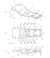
- FIG. 1 (a) is a perspective view of a resin-made arm
- FIG.1 (b) is a top view of a resin-made arm
- FIG.1 (c) is resin-made. It is a side view of an arm.
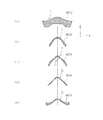
- 2A is a cross-sectional view taken along the line A1-A1 in FIG. 1B
- FIG. 2B is a cross-sectional view taken along the line A2-A2 in FIG. 1B
- FIG. 2 (c) is a cross-sectional view taken along line A3-A3 in FIG. 1 (b)
- FIG. 2 (d) is cut along line A4-A4 in FIG. 1 (b).
- FIG. 1 (a) is a perspective view of a resin-made arm
- FIG.1 (b) is a top view of a resin-made arm
- FIG.1 (c) is resin-made. It is a side view of an arm.
- 2A is a cross-sectional view taken along the line A1-A1 in
- FIG. 2E is a cross-sectional view taken along the line A5-A5 of FIG. 1B. It is a figure which shows the modification 1 of the resin-made arms of this invention
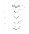
- Fig.3 (a) is sectional drawing of the arm main-body part corresponding to Fig.2 (a)
- 3C is a cross-sectional view of the arm main body corresponding to FIG. 2C
- FIG. 3D is a cross-sectional view of the arm main body corresponding to FIG.
- FIG.3 (e) is sectional drawing of the arm main-body part corresponding to FIG.2 (e).
- FIG. 1A is a perspective view of the resin arm 1.
- FIG. 1B is a plan view of the resin arm 1.
- FIG. 1C is a side view of the resin arm 1.
- 2A is a cross-sectional view of the resin arm 1 cut along the line A1-A1 of FIG. 1B (a cross-sectional view of the connection portion C1 of the arm main body 3 on the mounting portion 2 side).
- 2B is a cross-sectional view of the resin arm 1 cut along the line A2-A2 of FIG. 1B (first cross-sectional view of the arm main body 3).
- FIG. 1A is a perspective view of the resin arm 1.
- FIG. 1B is a plan view of the resin arm 1.
- FIG. 1C is a side view of the resin arm 1.
- 2A is a cross-sectional view of the resin arm 1 cut along the line A1-A1 of FIG. 1B (a cross-sectional view of the connection portion C1 of the arm main body 3 on the mounting portion 2 side).
- 2C is a sectional view of the resin arm 1 cut along the line A3-A3 of FIG. 1B (second sectional view of the arm main body 3).
- 2D is a cross-sectional view of the resin arm 1 cut along the line A4-A4 of FIG. 1B (third cross-sectional view of the arm main body 3).
- 2E is a cross-sectional view of the resin arm 1 cut along the line A5-A5 of FIG. 1B (a cross-sectional view of the connecting portion C5 of the arm main body 3 on the chuck portion 4 side). ).
- a mounting portion 2 fixed to a support frame 5 with a bolt 6 or the like is formed on the base end side (left end side in FIG. 1) (FIG. 12).
- the arm main body 3 is integrally formed at the end of the mounting portion 2, and the chuck 4 is integrally formed at the tip of the arm main body 3 (the right end in FIG. 1).
- the mounting portion 2 formed on the base end side of the resin arm 1 is a plate-like portion having a rectangular shape in plan view, is formed to have the same plate thickness, and is attached to a mounting hole (not shown) of the support frame 5. ),
- a pair of bolt holes 7 are formed along the width direction (the vertical direction in FIG.
- the resin arm 1 is configured such that the back surface 2b is abutted against the support frame 5 when one of the mounting portions 2 in the plate thickness direction is the front surface 2a and the other of the mounting portions 2 in the plate thickness direction is the back surface 2b.
- the longitudinal direction of the resin arm 1 means a direction along the X-axis direction of the XY plane when the imaginary plane including the surface 2a of the attachment portion 2 is an XY plane.
- the plate thickness direction of the attachment portion 2 refers to the Z-axis direction orthogonal to the XY plane.
- the width direction of the resin arm 1 is a direction along the Y-axis direction of the XY plane.
- the chuck portion 4 formed on the distal end side (the right end side in FIG. 1) of the resin arm 1 is formed with four pedestal portions 8 spaced apart from each other, and is attached to the attachment portion 2 via the arm main body portion 3. Connected together.
- a chuck 10 (for example, a vacuum chuck) that holds a molded product (three-dimensional modeled product, injection molded product, etc.) is attached to the base portion 8 of the chuck portion 4 (see FIG. 1C).
- the arm main body 3 has a cross section orthogonal to the longitudinal direction (perpendicular to the XY plane and orthogonal to the X-axis direction of the XY plane) when the direction from the mounting portion 2 toward the chuck portion 4 is the longitudinal direction.
- the connecting portion C5 with the chuck portion 4 is smaller in area than the connecting portion C1 with the mounting portion 2 (see FIGS. 2A and 2E).
- the arm body 3 is formed such that the dimension in the width direction gradually decreases from the portion C2 near the mounting portion 2 toward the portion C4 near the chuck portion 4 (FIGS. 2B to 2D). reference).
- the arm body 3 has a substantially W-shaped cross section at the connection portion C1 with the attachment portion 2 and the connection portion C5 with the chuck portion 4 (see FIGS. 2A and 2E).
- the cross-sectional shape in the range (C2 to C4) from the portion C2 near the portion 2 to the portion C4 near the chuck portion 4 is a substantially inverted V shape (see FIGS. 2B to 2D).
- the arm main body 3 has a cross-sectional shape in the vicinity of the connection portion C1 with the attachment portion 2 smoothly changes from a substantially W shape to a substantially inverted V shape, and in the vicinity of the connection portion C5 with the chuck portion 4.
- the cross-sectional shape is formed so as to smoothly change from a substantially inverted V shape to a substantially W shape.
- the arm main body part 3 includes a crest or valley part having a substantially W-shaped cross section of a connection part C1 with the attachment part 2 and a connection part C5 with the chuck part 4, and a chuck part 4 from a part C2 closer to the attachment part 2.
- a substantially inverted V-shaped peak or valley portion in the range (C 2 to C 4) up to the close portion C 4 extends along the longitudinal direction of the arm main body 3.
- the arm main body 3 has both ends in the width direction orthogonal to the longitudinal direction (both ends on both sides of the substantially W-shaped cross section) smoothly connected to both ends in the width direction of the mounting portion 2.
- the arm main body 3 is formed so as to gradually reduce the dimension in the width direction from the portion C2 near the attachment portion 2 to the portion C4 near the chuck portion 4.
- the arm main body 3 has a pair of through holes 11 and 11 for ventilation at the center in the longitudinal direction. Note that at least one through hole 11 may be formed.
- the arm main body portion 3 of the resin arm 1 having the above-described configuration has a connection portion with the chuck portion 4 when the cross-sectional area of the connection portion C1 with the attachment portion 2 (see FIG. 2A) is 1.0.
- the cross-sectional area of C5 (see FIG. 2 (e)) is 0.13.
- the arm body 3 of the resin arm 1 has a portion C2 near the mounting portion 2 between the connecting portion C1 with the mounting portion 2 and the connecting portion C5 with the chuck portion 4 (see FIG. 2B). ) Is 0.28, and the cross-sectional area at the portion C4 (see FIG. 2D) near the chuck portion 4 is 0.11.
- the arm body 3 is formed so that the dimension in the width direction gradually decreases from the portion C2 near the mounting portion 2 to the portion C4 near the chuck portion 4.
- the resin arm 1 according to the present embodiment has a portion (C3 to C5) closer to the chuck portion 4 of the arm body portion 3 than a portion (range C1 to C3) closer to the mounting portion 2 of the arm body portion 3. ) Is lighter.
- the resin arm 1 according to the present embodiment is lighter than the case where the entire weight is made of an aluminum alloy.
- the resin arm 1 according to the present embodiment has a pair of ventilation through holes 11 and 11 formed in the central portion in the longitudinal direction of the arm main body 3 so that it is difficult to receive air resistance during exercise. Yes.
- the resin arm 1 according to the present embodiment can reduce the bending due to the action of inertia caused by the rapid acceleration fluctuation, and can reduce the vibration.
- the natural frequency of the resin arm 1 and the natural frequency of the machine to which the resin arm 1 is attached (for example, the molded product take-out machine 100 in FIG. 12) can be shifted by a shape optimization design described later. Therefore, the occurrence of vibration due to the resonance phenomenon can be effectively prevented.
- the cross-sectional area ratio of the arm body 3 described above is a numerical example for making the resin arm 1 according to the present embodiment easy to understand, and is not limited to this numerical example, and required bending rigidity. It is appropriately changed according to (EI), natural frequency, and the like.
- the arm main body 3 of the resin arm 1 according to the present embodiment has a substantially W-shaped cross section at the connection portion C1 with the attachment portion 2 and the connection portion C5 with the chuck portion 4 (FIG. 2 ( a) and (e)), the cross-sectional shape in the range (C2 to C4) from the portion C2 near the mounting portion 2 to the portion C4 near the chuck portion 4 is a substantially inverted V-shape (FIG. 2B).
- the arm main body 3 of the resin arm 1 according to the present embodiment is closer to the mounting portion 2 where the influence of the bending moment is larger than that of a flat arm main body (not shown) having a rectangular cross section.
- the bending rigidity (EI) in the portion can be increased.
- the resin arm 1 according to the present embodiment is used in place of the conventional aluminum alloy arm 101 shown in FIG. 12, and the mounting portion 2 is fixed to the support frame 5 with bolts 6 or the like. 5 is attached in the form of a cantilever beam.
- the resin arm 1 is guided by the support frame 5 that moves along the guide rail 12 and moves between the standby position S1 and the take-out position S2 while repeating rapid acceleration and sudden stop.
- the rotary shaft 13 can be quickly turned and stopped quickly. As described above, the resin arm 1 is used in a state where a rapid acceleration fluctuation occurs.
- the resin arm 1 according to the present embodiment can reduce the overall weight as compared with the arm 101 made of an aluminum alloy as in the conventional example, and can make the sectional moment (I) larger than that of the flat plate shape.
- the bending rigidity (EI) can be made larger than that of a flat plate.
- the resin arm 1 according to the present embodiment hardly generates vibration even when used in a state in which a rapid acceleration fluctuation occurs.
- FIG. 3 is a view showing a cross-sectional shape of the arm main body 3 according to Modification 1 of the resin arm 1, and FIG. 3 (a) is a cross-sectional view of the arm main body 3 corresponding to FIG. 2 (a).
- 3 (b) is a cross-sectional view of the arm main body 3 corresponding to FIG. 2 (b)
- FIG. 3 (c) is a cross-sectional view of the arm main body 3 corresponding to FIG. 2 (c)
- FIG. FIG. 3E is a cross-sectional view of the arm main body 3 corresponding to FIG. 2E
- FIG. 3E is a cross-sectional view of the arm main body 3 corresponding to FIG.
- the resin arm 1 of the present invention is not limited to the above embodiment, and the cross-sectional shape of the arm main body 3 is appropriately set as long as the bending rigidity (EI) can be made larger than that of the flat arm main body. Can be changed.
- the arm main body 3 of the resin arm 1 according to the first modification has a substantially M-shaped cross section at the connection portion C1 with the attachment portion 2 and the connection portion C5 with the chuck portion 4 (FIG. 3 ( a) and (e)), the cross-sectional shape in the range (C2 to C4) from the portion C2 near the mounting portion 2 to the portion C4 near the chuck portion 4 is substantially V-shaped (FIG. 3B). To (d)).
- the arm main body portion 3 of the resin arm 1 according to the first modification example is a flat plate having a rectangular cross-sectional shape (the width dimension and the cross-sectional area at each position C1 to C5 are the same as those of the arm unit 3 of the present embodiment).
- the sectional moment (I) is increased, and the bending rigidity (EI) is increased.
- the resin arm 1 according to the first modification is unlikely to vibrate even when used in a state where a rapid acceleration fluctuation occurs.
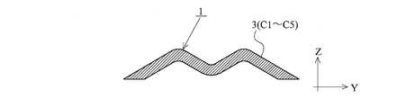
- FIG. 4 is a view showing a cross-sectional shape of the arm main body 3 according to the modification 2 of the resin arm 1.
- the arm main body 3 may have a substantially W-shaped cross section from the connection portion C1 to the attachment portion 2 to the connection portion C5 to the chuck portion 4 (FIG. 1 (b). )reference).
- the arm body 3 of the resin arm 1 according to the second modified example is a flat plate having a rectangular cross-sectional shape (the width dimension and the cross-sectional area at each position C1 to C5 are the same as those of the arm main body 3 of the present embodiment).
- the cross-sectional secondary moment (I) is increased, and the bending rigidity (EI) is increased.
- the resin arm 1 according to the second modification is less likely to vibrate even when used in a state where a rapid acceleration fluctuation occurs.
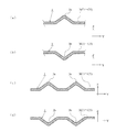
- FIG. 5 is a diagram illustrating a cross-sectional shape of the arm main body 3 according to the third modification of the resin arm 1.
- the arm main body 3 may have a substantially M-shaped cross section from the connection portion C1 to the attachment portion 2 to the connection portion C5 to the chuck portion 4 (FIG. 1 (b). )reference).
- the arm main body 3 of the resin arm 1 according to the third modification is a flat plate having a rectangular cross-sectional shape (the width dimension and the cross-sectional area at each position C1 to C5 are the same as those of the arm main body 3 of the present embodiment.
- the cross-sectional secondary moment (I) is increased, and the bending rigidity (EI) is increased.
- the resin arm 1 according to the third modification is less likely to vibrate even when used in a state where a rapid acceleration fluctuation occurs.
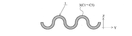
- FIG. 6 is a view showing a cross-sectional shape of the arm main body 3 according to the modification 4 of the resin arm 1.
- the arm main body 3 has a corrugated shape (for example, a cross-sectional shape from a connection portion C1 to the attachment portion 2 to a connection portion C5 to the chuck portion 4 is composed of a plurality of peaks and valleys (for example, A waveform shape in which a mountain-shaped curved surface (semi-circular curved surface) and a valley-shaped curved surface (semi-circular curved surface) are alternately and smoothly connected (see FIG. 1B).
- a corrugated shape for example, a cross-sectional shape from a connection portion C1 to the attachment portion 2 to a connection portion C5 to the chuck portion 4 is composed of a plurality of peaks and valleys (for example, A waveform shape in which a mountain-shaped curved surface (semi-circular curved surface) and a valley-shaped curved surface (
- the arm main body 3 of the resin arm 1 according to the fourth modification is a flat plate having a rectangular cross-sectional shape (the width dimension and the cross-sectional area at each position C1 to C5 are the same as those of the arm main body 3 of the present embodiment. ) Of the arm main body (not shown), the cross-sectional secondary moment (I) is increased, and the bending rigidity (EI) is increased. As a result, the resin arm 1 according to the fourth modification is less likely to vibrate even when used in a state where a rapid acceleration fluctuation occurs.
- FIG. 7 is a view showing a cross-sectional shape of the arm main body 3 according to the modified example 5 of the resin arm 1.
- the arm main body 3 may have a chevron-shaped portion 3a in a part of a cross section from the connection portion C1 to the attachment portion 2 to the connection portion C5 to the chuck portion 4.
- the arm main body 3 has a part of a cross section from the connection portion C1 to the attachment portion 2 to the connection portion C5 to the chuck portion 4 as a valley-shaped portion 3b (inverted mountain shape). (Shape part).
- the arm main-body part 3 makes the mountain-shaped part 3a, 3a the several location of the cross section from the connection part C1 with the attachment part 2 to the connection part C5 with the chuck
- the arm main body portion 3 has valley-shaped portions 3b, 3b (a plurality of cross-sections from the connection portion C1 to the attachment portion 2 to the connection portion C5 to the chuck portion 4). You may make it an inverted mountain-shaped part.
- the arm main body 3 of the resin arm 1 according to the fifth modified example is a flat plate having a rectangular cross-sectional shape (the width dimension and the cross-sectional area at each position C1 to C5 are the same as those of the arm main body 3 of the present embodiment). ) Of the arm main body (not shown), the cross-sectional secondary moment (I) is increased, and the bending rigidity (EI) is increased. As a result, the resin arm 1 according to the fifth modified example is less likely to vibrate even when used in a state where a rapid acceleration fluctuation occurs.
- FIG. 8 is a flowchart for explaining the method for manufacturing the resin arm 1 of the present invention (particularly, the portion related to the shape optimization design of the resin arm 1).
- FIG. 9 is a block diagram illustrating a method for manufacturing the resin arm 1 of the present invention.
- the resin arm 1 shown in FIGS. 8 and 9 has a resin arm 1 that is less susceptible to vibration even when used in a state in which rapid acceleration fluctuations occur compared to the conventional aluminum alloy arm 101. It was developed to produce
- the resin arm 1 manufacturing method creates 3D data of the current aluminum alloy arm 101 (hereinafter abbreviated as “arm”) (step S1).
- step S2 the 3D data of the arm 101 created in step S1 is input to the structure analysis software (for example, ANSYS) (step S2).
- the structure analysis software for example, ANSYS
- step S3 modal analysis is performed by the structure analysis software based on the 3D data and analysis conditions of the arm 101 input in step S2 (step S3).
- step S4 the natural frequency of the current arm 101 is calculated as a result of the modal analysis in step S3 (step S4).
- the resin arm 1 is manufactured by the current aluminum alloy arm when the natural frequency calculated in step S4 is within an allowable range (when the natural frequency does not resonate with the device to which the arm 101 is attached). 101 is used as it is (step S5). Further, when the natural frequency calculated in step S4 is out of the allowable range, the method for manufacturing the resin arm 1 proceeds to the stage of design optimization of the resin arm 1 (step S5).
- the manufacturing method of the resin arm 1 creates a 3D model of the shape optimization arm (not shown) (first step (step S6)).
- first step (step S6) the manufacturing method of the resin arm 1 creates a 3D model of the shape optimization arm (not shown) (first step (step S6)).
- the wall thickness is larger than the current arm 101.
- the shape-optimized arm has a pair of ventilation through holes 11 and 11 formed at the center in the longitudinal direction of the arm body 3 (see FIG. 1).
- the wall thickness is increased from that of the current arm 101 because the larger shape variation amount makes it easier to obtain the optimal shape of the arm.
- the pair of through holes 11 and 11 for ventilation are formed in the central portion in the longitudinal direction of the arm body 3 (see FIG. 1). This is to reduce the resistance of air received during exercise (straightly running, rotating, etc.).
- the manufacturing method of the resin arm 1 inputs the 3D data and analysis conditions created in step S6 to the structure analysis software (for example, ANSYS) (second step (step S7)).
- the analysis conditions include the arm material (for example, polyamide resin (PA)), the restraint location, the number of modes at the time of modal calculation, and the like.
- the manufacturing method of the resin arm 1 converts the 3D data and analysis conditions input to the structure analysis software into optimization software processing data of a data type that can be processed by optimization software (for example, OPTISHAPE), and the optimization
- the software processing data is transferred from the structure analysis software to the optimization software (third step (step S8)).
- step S8 the optimization calculation data is input to the optimization software to which the optimization software processing data has been transferred (fourth step (step S9)).
- the optimization calculation data includes “natural frequency” as an objective function and “volume 70%” as a constraint function, where “volume 70%” is the first step (step S6). This is the ratio of the created arm to the volume of the 3D model.
- the resin arm 1 is manufactured by optimizing the shape with the optimization software based on the optimization software processing data and the optimization calculation data, and the resin arm 1 (particularly, the arm main body 3).
- the external shape and the natural frequency of the resin arm 1 are calculated (fifth step (step S10)).
- the manufacturing method of the resin arm 1 determines whether or not the natural frequency calculated in the fifth step (step S10) is within an allowable range, and the natural frequency calculated in the fifth step (step S10). Is outside the allowable range, while changing the shape of the arm (step S12) until the natural frequency calculated in the fifth step (step S10) is within the allowable range (step S12), the fourth to fifth steps ( Steps S9 to S10) are repeatedly performed (sixth step (step S11)).
- the arm shape data changed in step S12 constitutes optimization calculation data.
- step S10 when the natural frequency calculated in the fifth step (step S10) is within the allowable range, the outer shape of the arm is determined as 3D data for manufacturing the arm ( Seventh step (S13)). Thereby, the shape optimization design of the arm in the manufacturing method of the resin arm 1 is completed.
- the resin arm 1 of the present invention calculates the outer shape of the arm body 3 so that the natural frequency of the resin arm 1 is within an allowable range (see FIG. 8).
- Steps S6 to S12 After the 3D data for manufacturing the resin arm 1 is determined (after the shape optimization setting step shown in Steps S6 to S13 in FIG. 8), the 3D data for manufacturing the resin arm 1 is 3D. It is input to a printer and manufactured by additive modeling using a 3D printer (3D printer modeling process).
- a present Example manufactures the resin-made arms 1 by the powder sintering lamination molding method of the additional shaping using a 3D printer
- Additional shaping other than the powder sintering lamination molding method (for example, , Inkjet method, stereolithography, hot melt lamination method).
- the natural frequency of the aluminum alloy arm 101 is calculated (steps S1 to S5).
- steps S1 to S5 in FIG. 8 are omitted.
- the steps S6 to S13 in FIG. 8 may be the first to seventh steps, and the shape optimization design of the resin arm 1 may be performed.
- step S5 and S11 by setting the allowable range of the natural frequency high (steps S5 and S11), even if it is used in a state in which a rapid acceleration fluctuation occurs, the vibration is generated.
- a lightweight and highly rigid resin arm is manufactured (see FIGS. 1 to 7).
- the resin arm according to the present embodiment can be widely applied to an arm of an industrial robot in addition to an arm for taking out a molded product of a molded product take-out machine attached to the injection molding apparatus.
Landscapes
- Engineering & Computer Science (AREA)
- Physics & Mathematics (AREA)
- Theoretical Computer Science (AREA)
- Materials Engineering (AREA)
- Chemical & Material Sciences (AREA)
- Manufacturing & Machinery (AREA)
- Evolutionary Computation (AREA)
- General Physics & Mathematics (AREA)
- General Engineering & Computer Science (AREA)
- Geometry (AREA)
- Computer Hardware Design (AREA)
- Mechanical Engineering (AREA)
- Optics & Photonics (AREA)
- Manipulator (AREA)
Abstract
【課題】急激な加速度変動が生じる状態で使用されても振動を生じにくい樹脂製アーム、及びその製造方法を提供する。 【解決手段】樹脂製アーム1は、取付部2とチャック部4とをアーム本体部3で接続している。アーム本体部3は、長手方向の中央部に通風用の貫通穴11,11が形成されている。アーム本体部3は、取付部2との接続部分C1及びチャック部4との接続部分C5における断面の形状が略W字形状であり、取付部寄りの部分C2からチャック部寄りの部分C4までの範囲(C2~C4)における断面の形状が略逆V字形状である。また、アーム本体部3の断面の形状は、略W字形状から略逆V字形状に滑らかに変化し、略逆V字形状から略W字形状に滑らかに変化する。このような樹脂製アーム1は、形状最適化設計により製造用3Dデータが作成され、3Dプリンタによる付加造形で製造される。
Description
この発明は、付加製造技術によって成形される付加造形物としての樹脂製アーム、及びその製造方法に関する。
近年、射出成形機に付設される成形品取り出し機は、射出成形サイクルの時間短縮を図るため、金型から成形品を取り出す成形品取り出し用のアームが高速で作動させられるようになっている。
図11は、このような成形品取り出し機100に使用される成形品取り出し用のアーム101を示す図である。また、図12は、成形品取り出し機100のアーム101の作動状態を簡略化して示す図である。これらの図に示すように、アーム101は、アルミ合金製で形成された板状体であり、基端側(図11の左端側)の取付部102が支持フレーム5に固定され、先端側(図11の右端側)のチャック部103に成形品を吸着するチャック10が取り付けられている。この取り出し用のアーム101は、待機位置S1と取り出し位置S2との間をガイドレール12に沿って移動する支持フレーム5で案内され、金型のキャビティ内の成形品(図示せず)をチャック10で吸着して、その成形品を金型から取り出すようになっている(特許文献1参照)。
このような成形品取り出し機100に使用される成形品取り出し用のアーム101は、サイクルタイムを短縮する必要から、待機位置S1と取り出し位置S2との間を往復移動する際の動作スピードを速めるようになっており、急加速、急停止を繰り返すため、急激な加速度変動に伴う振動を生じやすく、チャックで吸着した成形品を振動によって落下させてしまいやすくなる。
そこで、本発明は、急激な加速度変動が生じる状態で使用されても振動を生じにくい樹脂製アーム、及びその製造方法を提供する。
また、本発明は、基端側の取付部2と、先端側のチャック部4と、これら取付部2とチャック部4とを接続するアーム本体部3と、を備えた樹脂製アーム1に関するものである。
本発明において、前記アーム本体部3は、
(1).前記取付部2から前記チャック部4に向かう方向を長手方向とすると、前記長手方向の中央部に通風用の貫通穴11が形成され、
(2).前記取付部2との接続部分及び前記チャック部4との接続部分における前記長手方向に直交する断面の形状が略W字形状であり、
(3).前記取付部2寄りの部分から前記チャック部4寄りの部分までの範囲における前記断面の形状が略逆V字形状であり、
(4).前記取付部2との接続部分の近傍における前記断面の形状が略W字形状から略逆V字形状に滑らかに変化し、
(5).前記チャック部4との接続部分の近傍における前記断面の形状が略逆V字形状から略W字形状に滑らかに変化するようになっている。
本発明において、前記アーム本体部3は、
(1).前記取付部2から前記チャック部4に向かう方向を長手方向とすると、前記長手方向の中央部に通風用の貫通穴11が形成され、
(2).前記取付部2との接続部分及び前記チャック部4との接続部分における前記長手方向に直交する断面の形状が略W字形状であり、
(3).前記取付部2寄りの部分から前記チャック部4寄りの部分までの範囲における前記断面の形状が略逆V字形状であり、
(4).前記取付部2との接続部分の近傍における前記断面の形状が略W字形状から略逆V字形状に滑らかに変化し、
(5).前記チャック部4との接続部分の近傍における前記断面の形状が略逆V字形状から略W字形状に滑らかに変化するようになっている。
本発明は、基端側の取付部2と、先端側のチャック部4と、これら取付部2とチャック部4とを接続するアーム本体部3と、を備えた樹脂製アーム1の製造方法に関する。本発明に係る樹脂製アーム1の製造方法は、前記アーム1の固有振動数が許容範囲内になるように前記アーム本体部3の外形形状を算出し、前記アーム1の製造用3Dデータを決定する形状最適化設計工程と、前記アーム1の製造用3Dデータを使用し、3Dプリンタで前記アーム1の造形を行う3Dプリンタ造形工程と、を有している。
本発明に係る樹脂製アームは、従来例のようなアルミ合金製のアームよりも全体重量を軽減できると共に、断面二次モーメント(I)を平板形状のものよりも大きくすることができ、曲げ剛性(EI)を平板形状のものよりも大きくすることができる。その結果、本発明に係る樹脂製アームは、急激な加速度変動が生じる状態で使用されても振動を生じにくい。
以下、本発明の実施例を図面に基づき詳述する。
(樹脂製アームの実施例)
図1乃至図2は、後述する樹脂製アーム1の製造方法によって製造された樹脂製アーム1を示す図である。なお、図1(a)は、樹脂製アーム1の斜視図である。また、図1(b)は、樹脂製アーム1の平面図である。また、図1(c)は、樹脂製アーム1の側面図である。また、図2(a)は、図1(b)のA1-A1線に沿って切断して示す樹脂製アーム1の断面図(取付部2側におけるアーム本体部3の接続部分C1の断面図)である。また、図2(b)は、図1(b)のA2-A2線に沿って切断して示す樹脂製アーム1の断面図(アーム本体部3の第1の断面図)である。また、図2(c)は、図1(b)のA3-A3線に沿って切断して示す樹脂製アーム1の断面図(アーム本体部3の第2の断面図)である。また、図2(d)は、図1(b)のA4-A4線に沿って切断して示す樹脂製アーム1の断面図(アーム本体部3の第3の断面図)である。また、図2(e)は、図1(b)のA5-A5線に沿って切断して示す樹脂製アーム1の断面図(チャック部4側におけるアーム本体部3の接続部分C5の断面図)である。
図1乃至図2は、後述する樹脂製アーム1の製造方法によって製造された樹脂製アーム1を示す図である。なお、図1(a)は、樹脂製アーム1の斜視図である。また、図1(b)は、樹脂製アーム1の平面図である。また、図1(c)は、樹脂製アーム1の側面図である。また、図2(a)は、図1(b)のA1-A1線に沿って切断して示す樹脂製アーム1の断面図(取付部2側におけるアーム本体部3の接続部分C1の断面図)である。また、図2(b)は、図1(b)のA2-A2線に沿って切断して示す樹脂製アーム1の断面図(アーム本体部3の第1の断面図)である。また、図2(c)は、図1(b)のA3-A3線に沿って切断して示す樹脂製アーム1の断面図(アーム本体部3の第2の断面図)である。また、図2(d)は、図1(b)のA4-A4線に沿って切断して示す樹脂製アーム1の断面図(アーム本体部3の第3の断面図)である。また、図2(e)は、図1(b)のA5-A5線に沿って切断して示す樹脂製アーム1の断面図(チャック部4側におけるアーム本体部3の接続部分C5の断面図)である。
これらの図に示すように、本実施例に係る樹脂製アーム1は、支持フレーム5にボルト6等で固定される取付部2が基端側(図1の左端側)に形成され(図12参照)、この取付部2の端部にアーム本体部3が一体に形成され、このアーム本体部3の先端(図1の右端)にチャック部4が一体に形成されている。この樹脂製アーム1の基端側に形成された取付部2は、平面視した形状が矩形形状の板状部分であり、同一の板厚に形成され、支持フレーム5の取付穴(図示せず)に合致するようにボルト穴7が幅方向(図1(b)の上下方向であり、樹脂製アーム1の長手方向に直交する方向)に沿って一対形成されている。そして、この樹脂製アーム1は、取付部2の板厚方向の一方を表面2aとし、取付部2の板厚方向の他方を裏面2bとすると、裏面2bが支持フレーム5に突き当てられるようになっている。ここで、樹脂製アーム1の長手方向とは、取付部2の表面2aを含む仮想平面をX-Y平面とすると、そのX-Y平面のX軸方向に沿った方向をいうものとする。なお、取付部2の板厚方向とは、X-Y平面に直交するZ軸方向をいうものとする。また、樹脂製アーム1の幅方向とは、X-Y平面のY軸方向に沿った方向をいうものとする。
樹脂製アーム1の先端側(図1の右端側)に形成されたチャック部4は、4箇所の台座部分8が間隔を開けて形成されており、アーム本体部3を介して取付部2に一体に接続されている。このチャック部4の台座部分8には、成形品(3次元造形物、射出成形品等)を掴むチャック10(例えば、真空チャック)が取り付けられる(図1(c)参照)。
アーム本体部3は、取付部2からチャック部4に向かう方向を長手方向とすると、この長手方向に直交する断面(X-Y平面に直交し、且つ、X-Y平面のX軸方向に直交する断面)の面積が、取付部2との接続部分C1よりもチャック部4との接続部分C5の方が小さくなるように形成されている(図2(a)、(e)参照)。また、アーム本体部3は、その幅方向の寸法が取付部2寄りの部分C2からチャック部4寄りの部分C4へ向かうに従って漸減するように形成されている(図2(b)~(d)参照)。また、アーム本体部3は、取付部2との接続部分C1及びチャック部4との接続部分C5における断面の形状が略W字形状であり(図2(a)、(e)参照)、取付部2寄りの部分C2からチャック部4寄りの部分C4までの範囲(C2~C4)における断面の形状が略逆V字形状である(図2(b)~(d)参照)。また、アーム本体部3は、取付部2との接続部分C1の近傍における断面の形状が略W字形状から略逆V字形状に滑らかに変化し、チャック部4との接続部分C5の近傍における断面の形状が略逆V字形状から略W字形状に滑らかに変化するように形成されている。また、アーム本体部3は、取付部2との接続部分C1及びチャック部4との接続部分C5の断面略W字形状の山又は谷の部分と、取付部2寄りの部分C2からチャック部4寄りの部分C4までの範囲(C2~C4)における略逆V字形状の山又は谷の部分とが、アーム本体部3の長手方向に沿うように延びている。また、アーム本体部3は、長手方向に直交する幅方向の両端(略W字形状の断面の両側端)が取付部2の幅方向の両端に滑らかに接続されている。また、アーム本体部3は、幅方向の寸法を取付部2寄りの部分C2からチャック部4寄りの部分C4まで漸減するように形成されている。また、アーム本体部3は、長手方向の中央部に通風用の貫通穴11,11が一対形成されている。なお、貫通穴11は、少なくとも1箇所形成されていればよい。
以上のような構成の樹脂製アーム1のアーム本体部3は、取付部2との接続部分C1の断面積(図2(a)参照)を1.0とすると、チャック部4との接続部分C5の断面積(図2(e)参照)が0.13である。また、この樹脂製アーム1のアーム本体部3は、取付部2との接続部分C1とチャック部4との接続部分C5との間において、取付部2寄りの部分C2(図2(b)参照)の断面積が0.28であり、チャック部4寄りの部分C4(図2(d)参照)における断面積が0.11である。そして、アーム本体部3は、その幅方向の寸法が取付部2寄りの部分C2からチャック部4寄りの部分C4まで漸減するように形成されている。このように、本実施例に係る樹脂製アーム1は、アーム本体部3の取付部2寄りの部分(C1~C3の範囲)よりもアーム本体部3のチャック部4寄りの部分(C3~C5)の方が軽くなるような形状に形成されている。また、本実施例に係る樹脂製アーム1は、全体の重量がアルミ合金で製造される場合よりも軽くなる。また、本実施例に係る樹脂製アーム1は、アーム本体部3の長手方向の中央部に通風用の貫通穴11,11が一対形成されており、運動時の空気の抵抗を受けにくくなっている。したがって、本実施例に係る樹脂製アーム1は、急激な加速度変動によって生じる慣性の作用による撓みを少なくすることができ、振動を少なくすることができる。しかも、樹脂製アーム1は、その固有振動数と樹脂製アーム1が取り付けられる機械(例えば、図12の成形品取り出し機100)の固有振動数を後述する形状最適化設計によってずらすことが可能であるため(図8、図10参照)、共振現象に起因する振動の発生を効果的に防止できる。なお、上記したアーム本体部3の断面積比は、本実施例に係る樹脂製アーム1を分かりやすくするための数値例であり、この数値例に限定されるものでなく、要求される曲げ剛性(EI)や固有振動数等に応じて適宜変更される。
また、本実施例に係る樹脂製アーム1のアーム本体部3は、取付部2との接続部分C1及びチャック部4との接続部分C5における断面の形状が略W字形状であり(図2(a)、(e)参照)、取付部2寄りの部分C2からチャック部4寄りの部分C4までの範囲(C2~C4)における断面の形状が略逆V字形状である(図2(b)~(d)参照)。その結果、本実施例に係る樹脂製アーム1のアーム本体部3は、断面形状が矩形形状の平板のアーム本体部(図示せず)と比較し、曲げモーメントの影響が大きい取付部2寄りの部分における曲げ剛性(EI)を大きくすることができる。
(使用例)
本実施例に係る樹脂製アーム1は、図12に示したアルミ合金製の従来のアーム101に代えて使用され、取付部2が支持フレーム5にボルト6等で固定されることにより、支持フレーム5の先端側に片持ち梁状に取り付けられる。そして、この樹脂製アーム1は、ガイドレール12に沿って移動する支持フレーム5で案内され、待機位置S1と取り出し位置S2との間を急加速・急停止を繰り返しながら移動し、また支持フレーム5の回動軸13を支点として急速回動・急停止をさせられる。このように、樹脂製アーム1は、急激な加速度変動が生じる状態で使用されることになる。
本実施例に係る樹脂製アーム1は、図12に示したアルミ合金製の従来のアーム101に代えて使用され、取付部2が支持フレーム5にボルト6等で固定されることにより、支持フレーム5の先端側に片持ち梁状に取り付けられる。そして、この樹脂製アーム1は、ガイドレール12に沿って移動する支持フレーム5で案内され、待機位置S1と取り出し位置S2との間を急加速・急停止を繰り返しながら移動し、また支持フレーム5の回動軸13を支点として急速回動・急停止をさせられる。このように、樹脂製アーム1は、急激な加速度変動が生じる状態で使用されることになる。
(本実施例の効果)
本実施例に係る樹脂製アーム1は、従来例のようなアルミ合金製のアーム101よりも全体重量を軽減できると共に、断面二次モーメント(I)を平板形状のものよりも大きくすることができ、曲げ剛性(EI)を平板形状のものよりも大きくすることができる。その結果、本実施例に係る樹脂製アーム1は、急激な加速度変動が生じる状態で使用されても振動を生じにくい。
本実施例に係る樹脂製アーム1は、従来例のようなアルミ合金製のアーム101よりも全体重量を軽減できると共に、断面二次モーメント(I)を平板形状のものよりも大きくすることができ、曲げ剛性(EI)を平板形状のものよりも大きくすることができる。その結果、本実施例に係る樹脂製アーム1は、急激な加速度変動が生じる状態で使用されても振動を生じにくい。
(樹脂製アームの変形例1)
図3は、樹脂製アーム1の変形例1に係るアーム本体部3の断面形状を示す図であり、図3(a)が図2(a)に対応するアーム本体部3の断面図、図3(b)が図2(b)に対応するアーム本体部3の断面図、図3(c)が図2(c)に対応するアーム本体部3の断面図、図3(d)が図2(d)に対応するアーム本体部3の断面図、図3(e)が図2(e)に対応するアーム本体部3の断面図である。
図3は、樹脂製アーム1の変形例1に係るアーム本体部3の断面形状を示す図であり、図3(a)が図2(a)に対応するアーム本体部3の断面図、図3(b)が図2(b)に対応するアーム本体部3の断面図、図3(c)が図2(c)に対応するアーム本体部3の断面図、図3(d)が図2(d)に対応するアーム本体部3の断面図、図3(e)が図2(e)に対応するアーム本体部3の断面図である。
本発明の樹脂製アーム1は、上記実施例に限定されるものでなく、平板形状のアーム本体部よりも曲げ剛性(EI)を大きくすることができる限り、アーム本体部3の断面形状を適宜変更することができる。例えば、本変形例1に係る樹脂製アーム1のアーム本体部3は、取付部2との接続部分C1及びチャック部4との接続部分C5における断面の形状を略M字形状にし(図3(a)、(e)参照)、取付部2寄りの部分C2からチャック部4寄りの部分C4までの範囲(C2~C4)における断面の形状を略V字形状にしてある(図3(b)~(d)参照)。このような本変形例1に係る樹脂製アーム1のアーム本体部3は、断面形状が矩形形状の平板(各位置C1~C5における幅寸法及び断面積が本実施例のアーム部3と同一)のアーム本体部(図示せず)と比較し、断面二次モーメント(I)が大きくなり、曲げ剛性(EI)が大きくなる。その結果、本変形例1に係る樹脂製アーム1は、急激な加速度変動が生じる状態で使用されても振動を生じにくい。
(樹脂製アームの変形例2)
図4は、樹脂製アーム1の変形例2に係るアーム本体部3の断面形状を示す図である。この図4に示すように、アーム本体部3は、取付部2との接続部分C1からチャック部4との接続部分C5までの断面の形状を略W字形状にしてもよい(図1(b)参照)。このような本変形例2に係る樹脂製アーム1のアーム本体部3は、断面形状が矩形形状の平板(各位置C1~C5における幅寸法及び断面積が本実施例のアーム本体部3と同一)のアーム本体部(図示せず)と比較し、断面二次モーメント(I)が大きくなり、曲げ剛性(EI)が大きくなる。その結果、本変形例2に係る樹脂製アーム1は、急激な加速度変動が生じる状態で使用されても振動を生じにくい。
図4は、樹脂製アーム1の変形例2に係るアーム本体部3の断面形状を示す図である。この図4に示すように、アーム本体部3は、取付部2との接続部分C1からチャック部4との接続部分C5までの断面の形状を略W字形状にしてもよい(図1(b)参照)。このような本変形例2に係る樹脂製アーム1のアーム本体部3は、断面形状が矩形形状の平板(各位置C1~C5における幅寸法及び断面積が本実施例のアーム本体部3と同一)のアーム本体部(図示せず)と比較し、断面二次モーメント(I)が大きくなり、曲げ剛性(EI)が大きくなる。その結果、本変形例2に係る樹脂製アーム1は、急激な加速度変動が生じる状態で使用されても振動を生じにくい。
(樹脂製アームの変形例3)
図5は、樹脂製アーム1の変形例3に係るアーム本体部3の断面形状を示す図である。この図5に示すように、アーム本体部3は、取付部2との接続部分C1からチャック部4との接続部分C5までの断面の形状を略M字形状にしてもよい(図1(b)参照)。このような本変形例3に係る樹脂製アーム1のアーム本体部3は、断面形状が矩形形状の平板(各位置C1~C5における幅寸法及び断面積が本実施例のアーム本体部3と同一)のアーム本体部(図示せず)と比較し、断面二次モーメント(I)が大きくなり、曲げ剛性(EI)が大きくなる。その結果、本変形例3に係る樹脂製アーム1は、急激な加速度変動が生じる状態で使用されても振動を生じにくい。
図5は、樹脂製アーム1の変形例3に係るアーム本体部3の断面形状を示す図である。この図5に示すように、アーム本体部3は、取付部2との接続部分C1からチャック部4との接続部分C5までの断面の形状を略M字形状にしてもよい(図1(b)参照)。このような本変形例3に係る樹脂製アーム1のアーム本体部3は、断面形状が矩形形状の平板(各位置C1~C5における幅寸法及び断面積が本実施例のアーム本体部3と同一)のアーム本体部(図示せず)と比較し、断面二次モーメント(I)が大きくなり、曲げ剛性(EI)が大きくなる。その結果、本変形例3に係る樹脂製アーム1は、急激な加速度変動が生じる状態で使用されても振動を生じにくい。
(樹脂製アームの変形例4)
図6は、樹脂製アーム1の変形例4に係るアーム本体部3の断面形状を示す図である。この図6に示すように、アーム本体部3は、取付部2との接続部分C1からチャック部4との接続部分C5までの断面の形状が複数の山と谷から構成される波形形状(例えば、山形の曲面(半円形の曲面)と谷形の曲面(半円形の曲面)を交互に滑らかに接続したような波形形状)である(図1(b)参照)。このような本変形例4に係る樹脂製アーム1のアーム本体部3は、断面形状が矩形形状の平板(各位置C1~C5における幅寸法及び断面積が本実施例のアーム本体部3と同一)のアーム本体部(図示せず)と比較し、断面二次モーメント(I)が大きくなり、曲げ剛性(EI)が大きくなる。その結果、本変形例4に係る樹脂製アーム1は、急激な加速度変動が生じる状態で使用されても振動を生じにくい。
図6は、樹脂製アーム1の変形例4に係るアーム本体部3の断面形状を示す図である。この図6に示すように、アーム本体部3は、取付部2との接続部分C1からチャック部4との接続部分C5までの断面の形状が複数の山と谷から構成される波形形状(例えば、山形の曲面(半円形の曲面)と谷形の曲面(半円形の曲面)を交互に滑らかに接続したような波形形状)である(図1(b)参照)。このような本変形例4に係る樹脂製アーム1のアーム本体部3は、断面形状が矩形形状の平板(各位置C1~C5における幅寸法及び断面積が本実施例のアーム本体部3と同一)のアーム本体部(図示せず)と比較し、断面二次モーメント(I)が大きくなり、曲げ剛性(EI)が大きくなる。その結果、本変形例4に係る樹脂製アーム1は、急激な加速度変動が生じる状態で使用されても振動を生じにくい。
(樹脂製アームの変形例5)
図7は、樹脂製アーム1の変形例5に係るアーム本体部3の断面形状を示す図である。図7(a)に示すように、アーム本体部3は、取付部2との接続部分C1からチャック部4との接続部分C5までの断面の一部を山形形状部分3aにしてもよい。また、図7(b)に示すように、アーム本体部3は、取付部2との接続部分C1からチャック部4との接続部分C5までの断面の一部を谷形形状部分3b(逆山形形状部分)にしてもよい。また、図7(c)に示すように、アーム本体部3は、取付部2との接続部分C1からチャック部4との接続部分C5までの断面の複数箇所を山形形状部分3a,3aにしてもよい。また、図7(d)に示すように、アーム本体部3は、取付部2との接続部分C1からチャック部4との接続部分C5までの断面の複数箇所を谷形形状部分3b,3b(逆山形形状部分)にしてもよい。このような本変形例5に係る樹脂製アーム1のアーム本体部3は、断面形状が矩形形状の平板(各位置C1~C5における幅寸法及び断面積が本実施例のアーム本体部3と同一)のアーム本体部(図示せず)と比較し、断面二次モーメント(I)が大きくなり、曲げ剛性(EI)が大きくなる。その結果、本変形例5に係る樹脂製アーム1は、急激な加速度変動が生じる状態で使用されても振動を生じにくい。
図7は、樹脂製アーム1の変形例5に係るアーム本体部3の断面形状を示す図である。図7(a)に示すように、アーム本体部3は、取付部2との接続部分C1からチャック部4との接続部分C5までの断面の一部を山形形状部分3aにしてもよい。また、図7(b)に示すように、アーム本体部3は、取付部2との接続部分C1からチャック部4との接続部分C5までの断面の一部を谷形形状部分3b(逆山形形状部分)にしてもよい。また、図7(c)に示すように、アーム本体部3は、取付部2との接続部分C1からチャック部4との接続部分C5までの断面の複数箇所を山形形状部分3a,3aにしてもよい。また、図7(d)に示すように、アーム本体部3は、取付部2との接続部分C1からチャック部4との接続部分C5までの断面の複数箇所を谷形形状部分3b,3b(逆山形形状部分)にしてもよい。このような本変形例5に係る樹脂製アーム1のアーム本体部3は、断面形状が矩形形状の平板(各位置C1~C5における幅寸法及び断面積が本実施例のアーム本体部3と同一)のアーム本体部(図示せず)と比較し、断面二次モーメント(I)が大きくなり、曲げ剛性(EI)が大きくなる。その結果、本変形例5に係る樹脂製アーム1は、急激な加速度変動が生じる状態で使用されても振動を生じにくい。
(樹脂製ア-ムの製造方法)
図8は、本発明の樹脂製アーム1の製造方法(特に、樹脂製アーム1の形状最適化設計に関係する部分)を説明するためのフローチャート図である。また、図9は、本発明の樹脂製アーム1の製造方法を説明するブロック図である。これら図8及び図9に示す樹脂製アーム1の製造方法は、従来のアルミ合金製アーム101と比較し、急激な加速度変動が生じる状態で使用されたとしても、振動が生じにくい樹脂製アーム1を製造するために開発されたものである。
図8は、本発明の樹脂製アーム1の製造方法(特に、樹脂製アーム1の形状最適化設計に関係する部分)を説明するためのフローチャート図である。また、図9は、本発明の樹脂製アーム1の製造方法を説明するブロック図である。これら図8及び図9に示す樹脂製アーム1の製造方法は、従来のアルミ合金製アーム101と比較し、急激な加速度変動が生じる状態で使用されたとしても、振動が生じにくい樹脂製アーム1を製造するために開発されたものである。
この図8に示すように、樹脂製アーム1の製造方法は、現行のアルミ合金製アーム101(以下、アームと略称する)の3Dデータを作成する(ステップS1)。
次に、樹脂製アーム1の製造方法は、ステップS1で作成したアーム101の3Dデータを構造解析ソフト(例えば、ANSYS)に入力する(ステップS2)。
次に、樹脂製アーム1の製造方法は、ステップS2において入力したアーム101の3Dデータ及び解析条件基づき、構造解析ソフトによってモーダル解析が行われる(ステップS3)。
次に、樹脂製アーム1の製造方法は、ステップS3のモーダル解析の結果、現行のアーム101の固有振動数が算出される(ステップS4)。
次に、樹脂製アーム1の製造方法は、ステップS4において算出された固有振動数が許容範囲内の場合(アーム101が取り付けられる装置と共振しない固有振動数の場合)、現行のアルミ合金製アーム101をそのまま使用することになる(ステップS5)。また、樹脂製アーム1の製造方法は、ステップS4において算出された固有振動数が許容範囲外である場合、樹脂製アーム1の形状最適化設計の段階へ移行する(ステップS5)。
次に、樹脂製アーム1の形状最適化設計の段階において、樹脂製アーム1の製造方法は、形状最適化用のアーム(図示せず)の3Dモデルを作成する(第1工程(ステップS6))。ここで、形状最適化用のアームの3Dモデルは、現行のアーム101の基端側に位置する取付部102及び先端側に位置するチャック部103の形状を変更することなく、アーム本体部3の肉厚を現行のアーム101よりも増やしている。また、形状最適化のアームは、アーム本体部3の長手方向の中央部に通風用の貫通穴11,11が一対形成されるようになっている(図1参照)。なお、形状最適化用のアームの3Dデータにおいて、肉厚を現行のアーム101よりも増やしているのは、形状変動量が大きい方がアームの最適な形を得やすいためである。また、形状最適化用のアームの3Dデータにおいて、アーム本体部3の長手方向の中央部に通風用の貫通穴11,11が一対形成されているのは(図1参照)、樹脂製アームの運動時(直進時、回転時等)に受ける空気の抵抗を軽減するためである。
次に、樹脂製アーム1の製造方法は、ステップS6において作成した3Dデータ及び解析条件を構造解析ソフト(例えば、ANSYS)に入力する(第2工程(ステップS7))。なお、解析条件は、アームの材料(例えば、ポリアミド樹脂(PA))、拘束箇所、及びモーダル計算時のモード数等である。
次に、樹脂製アーム1の製造方法は、構造解析ソフトに入力した3Dデータ及び解析条件を最適化ソフト(例えば、OPTISHAPE)で処理できるデータ型式の最適化ソフト処理データに変換し、その最適化ソフト処理データを構造解析ソフトから最適化ソフトに転送する(第3工程(ステップS8))。
次に、樹脂製アーム1の製造方法は、ステップS8において、最適化ソフト処理データが転送された最適化ソフトに、最適化計算用データを入力する(第4工程(ステップS9))。なお、最適化計算用データは、目的関数としての「固有振動数」と、制約関数としての「体積70%]である。ここで、「体積70%」は、第1工程(ステップS6)で作成したアームの3Dモデルの体積に対する割合である。
次に、樹脂製アーム1の製造方法は、最適化ソフト処理データ及び最適化計算用データに基づいて、最適化ソフトで形状最適化を行い、樹脂製アーム1(特に、アーム本体部3)の外形形状と樹脂製アーム1の固有振動数を算出する(第5工程(ステップS10))。
次に、樹脂製アーム1の製造方法は、第5工程(ステップS10)で算出された固有振動数が許容範囲内か否か判断し、第5工程(ステップS10)で算出された固有振動数が許容範囲外である場合に、第5工程(ステップS10)で算出された固有振動数が許容範囲内になるまで、アームの形状を変えながら(ステップS12)、第4工程乃至第5工程(ステップS9~S10)を繰り返し行わせる(第6工程(ステップS11))。なお、ステップS12で変更されるアームの形状データは、最適化計算用データを構成する。
次に、樹脂製アーム1の製造方法は、第5工程(ステップS10)で算出された固有振動数が許容範囲内である場合に、アームの外形形状をアームの製造用3Dデータとして決定する(第7工程(S13))。これにより、樹脂製アーム1の製造方法におけるアームの形状最適化設計が終了する。
次に、図9に示すように、本発明の樹脂製アーム1は、樹脂製アーム1の固有振動数が許容範囲内になるようにアーム本体部3の外形形状を算出して(図8のステップS6~S12)、樹脂製アーム1の製造用3Dデータを決定した後(図8のステップS6~S13で示す形状最適化設定工程を経た後)、樹脂製アーム1の製造用3Dデータを3Dプリンタに入力し、3Dプリンタを使用した付加造形(3Dプリンタ造形工程)によって製造されるようになっている。なお、本実施例は、3Dプリンタを使用した付加造形のうちの粉末焼結積層造形法によって樹脂製アーム1を製造するが、これに限られず、粉末焼結積層造形法以外の付加造形(例えば、インクジェット法、光造形法、熱溶解積層法)で製造してもよい。
なお、本実施例は、アルミ合金製のアーム101の固有振動数を算出するようになっているが(ステップS1~S5)、図10に示すように、図8のステップS1~S5を省略し、図8のステップS6~S13までを第1乃至第7工程として、樹脂製アーム1の形状最適化設計を行うようにしてもよい。
以上の本実施例に係る樹脂製アーム1の製造方法によれば、固有振動数の許容範囲を高く設定することにより(ステップS5、S11)、急激な加速度変動が生じる状態で使用されても振動を生じにくく、軽量で高剛性の樹脂製アームが製造される(図1乃至図7参照)。
(その他の使用例)
なお、本実施例に係る樹脂製アームは、射出成形装置に付設される成形品取り出し機の成形品取り出し用のアームの他に、産業用ロボットのアーム等に広く適用できる。
なお、本実施例に係る樹脂製アームは、射出成形装置に付設される成形品取り出し機の成形品取り出し用のアームの他に、産業用ロボットのアーム等に広く適用できる。
1……樹脂製アーム、2……取付部、3……アーム部、4……チャック部、11……貫通穴
Claims (8)
- 基端側の取付部と、先端側のチャック部と、これら取付部とチャック部とを接続するアーム本体部と、を備えた樹脂製アームにおいて、
前記アーム本体部は、
(1).前記取付部から前記チャック部に向かう方向を長手方向とすると、前記長手方向の中央部に通風用の貫通穴が形成され、
(2).前記取付部との接続部分及び前記チャック部との接続部分における前記長手方向に直交する断面の形状が略W字形状であり、
(3).前記取付部寄りの部分から前記チャック部寄りの部分までの範囲における前記断面の形状が略逆V字形状であり、
(4).前記取付部との接続部分の近傍における前記断面の形状が略W字形状から略逆V字形状に滑らかに変化し、
(5).前記チャック部との接続部分の近傍における前記断面の形状が略逆V字形状から略W字形状に滑らかに変化する、
ことを特徴とする樹脂製アーム。 - 基端側の取付部と、先端側のチャック部と、これら取付部とチャック部とを接続するアーム本体部と、を備えた樹脂製アームにおいて、
前記アーム本体部は、
(1).前記取付部から前記チャック部に向かう方向を長手方向とすると、前記長手方向の中央部に通風用の貫通穴が形成され、
(2).前記取付部との接続部分及び前記チャック部との接続部分における前記長手方向に直交する断面の形状が略M字形状であり、
(3).前記取付部寄りの部分から前記チャック部寄りの部分までの範囲における前記断面の形状が略V字形状であり、
(4).前記取付部との接続部分の近傍における前記断面の形状が略M字形状から略V字形状に滑らかに変化し、
(5).前記チャック部との接続部分の近傍における前記断面の形状が略V字形状から略M字形状に滑らかに変化する、
ことを特徴とする樹脂製アーム。 - 基端側の取付部と、先端側のチャック部と、これら取付部とチャック部とを接続するアーム本体部と、を備えた樹脂製アームにおいて、
前記アーム本体部は、
(1).前記取付部から前記チャック部に向かう方向を長手方向とすると、前記長手方向の中央部に通風用の貫通穴が形成され、
(2).前記取付部との接続部分から前記チャック部との接続部分までの前記長手方向に直交する断面の形状が略W字形状である、
ことを特徴とする樹脂製アーム。 - 基端側の取付部と、先端側のチャック部と、これら取付部とチャック部とを接続するアーム本体部と、を備えた樹脂製アームにおいて、
前記アーム本体部は、
(1).前記取付部から前記チャック部に向かう方向を長手方向とすると、前記長手方向の中央部に通風用の貫通穴が形成され、
(2).前記取付部との接続部分から前記チャック部との接続部分までの前記長手方向に直交する断面の形状が略M字形状である、
ことを特徴とする樹脂製アーム。 - 基端側の取付部と、先端側のチャック部と、これら取付部とチャック部とを接続するアーム本体部と、を備えた樹脂製アームにおいて、
前記アーム本体部は、
(1).前記取付部から前記チャック部に向かう方向を長手方向とすると、前記長手方向の中央部に通風用の貫通穴が形成され、
(2).前記取付部との接続部分から前記チャック部との接続部分までの前記長手方向に直交する断面の形状が複数の山形の曲面を滑らかに接続したような略波形形状である、
ことを特徴とする樹脂製アーム。 - 基端側の取付部と、先端側のチャック部と、これら取付部とチャック部とを接続するアーム本体部と、を備えた樹脂製アームにおいて、
前記アーム本体部は、
(1).前記取付部から前記チャック部に向かう方向を長手方向とすると、前記長手方向の中央部に通風用の貫通穴が形成され、
(2).前記取付部との接続部分から前記チャック部との接続部分までの前記長手方向に直交する断面の形状が山形形状部分又は谷形形状部分を有する、
ことを特徴とする樹脂製アーム。 - 基端側の取付部と、先端側のチャック部と、これら取付部とチャック部とを接続するアーム本体部と、を備えた樹脂製アームの製造方法において、
前記アームの固有振動数が許容範囲内になるように前記アーム本体部の外形形状を算出し、前記アームの製造用3Dデータを決定する形状最適化設計工程と、
前記アームの製造用3Dデータを使用し、3Dプリンタで前記アームの造形を行う3Dプリンタ造形工程と、
を有することを特徴とする樹脂製アームの製造方法。 - 基端側の取付部と、先端側のチャック部と、これら取付部とチャック部とを接続するアーム本体部と、を備えた樹脂製アームの製造方法において、
前記アームの3Dデータを作成する第1工程と、
前記第1工程で作成した前記3Dデータ及び解析条件を構造解析ソフトに入力する第2工程と、
前記構造解析ソフトに入力した前記3Dデータ及び解析条件を最適化ソフトで処理できるデータ形式の最適化ソフト処理用データに変換し、前記最適化ソフト処理用データを前記構造解析ソフトから前記最適化ソフトに転送する第3工程と、
前記最適化ソフト処理用データが転送された前記最適化ソフトに最適化計算用データを入力する第4工程と、
前記最適化ソフト処理用データ及び前記最適化計算用データに基づいて前記最適化ソフトによって形状最適化を行い、前記アームの外形形状と固有振動数を算出する第5工程と、
前記第5工程で算出された前記固有振動数が許容範囲内か否かを判断し、前記第5工程で算出された前記固有振動数が許容範囲外である場合に、前記第5工程で算出した前記固有振動数が許容範囲内になるまでアームの形状を変えながら前記第4乃至第5工程を繰り返し行わせる第6工程と、
前記第5工程で算出された前記固有振動数が許容範囲内である場合に、前記アームの外形形状をアームの製造用3Dデータとして決定する第7工程と、
前記第7工程で決定された前記アームの製造用3Dデータを使用して3Dプリンタでアームの造形を行う第8工程と、を備え、
前記解析条件は、少なくとも前記アームの材料、拘束箇所、及びモーダル計算時のモード数であり、
前記最適化計算用データは、目的関数としての最適化計算用固有振動数と、制約関数としての体積比率、変数としての前記アームの最適化計算用外形形状であり、
前記拘束箇所は、前記取付部及び前記チャック部であり、
前記体積比率は、前記第1工程で作成した前記3Dデータのアーム本体部の体積に対する比率である、
ことを特徴とする樹脂製アームの製造方法。
Applications Claiming Priority (2)
| Application Number | Priority Date | Filing Date | Title |
|---|---|---|---|
| JP2016124374A JP2017226158A (ja) | 2016-06-23 | 2016-06-23 | 樹脂製アーム及びその製造方法 |
| JP2016-124374 | 2016-06-23 |
Publications (1)
| Publication Number | Publication Date |
|---|---|
| WO2017221566A1 true WO2017221566A1 (ja) | 2017-12-28 |
Family
ID=60784618
Family Applications (1)
| Application Number | Title | Priority Date | Filing Date |
|---|---|---|---|
| PCT/JP2017/017533 Ceased WO2017221566A1 (ja) | 2016-06-23 | 2017-05-09 | 樹脂製アーム及びその製造方法 |
Country Status (2)
| Country | Link |
|---|---|
| JP (1) | JP2017226158A (ja) |
| WO (1) | WO2017221566A1 (ja) |
Citations (4)
| Publication number | Priority date | Publication date | Assignee | Title |
|---|---|---|---|---|
| JPH11235738A (ja) * | 1998-02-20 | 1999-08-31 | Yushin Precision Equipment Co Ltd | 樹脂成形品の取出装置を備えた射出成形機 |
| JP2002059466A (ja) * | 2000-08-17 | 2002-02-26 | Takagi Ind Co Ltd | 成形品の取出方法及びその装置 |
| JP2007283679A (ja) * | 2006-04-18 | 2007-11-01 | Sumitomo Heavy Ind Ltd | 取出し機の制御装置 |
| JP2010111012A (ja) * | 2008-11-06 | 2010-05-20 | Yushin Precision Equipment Co Ltd | 成形品取出装置 |
-
2016
- 2016-06-23 JP JP2016124374A patent/JP2017226158A/ja active Pending
-
2017
- 2017-05-09 WO PCT/JP2017/017533 patent/WO2017221566A1/ja not_active Ceased
Patent Citations (4)
| Publication number | Priority date | Publication date | Assignee | Title |
|---|---|---|---|---|
| JPH11235738A (ja) * | 1998-02-20 | 1999-08-31 | Yushin Precision Equipment Co Ltd | 樹脂成形品の取出装置を備えた射出成形機 |
| JP2002059466A (ja) * | 2000-08-17 | 2002-02-26 | Takagi Ind Co Ltd | 成形品の取出方法及びその装置 |
| JP2007283679A (ja) * | 2006-04-18 | 2007-11-01 | Sumitomo Heavy Ind Ltd | 取出し機の制御装置 |
| JP2010111012A (ja) * | 2008-11-06 | 2010-05-20 | Yushin Precision Equipment Co Ltd | 成形品取出装置 |
Also Published As
| Publication number | Publication date |
|---|---|
| JP2017226158A (ja) | 2017-12-28 |
Similar Documents
| Publication | Publication Date | Title |
|---|---|---|
| JP6592519B2 (ja) | 可撓性ヒンジのトポロジー最適化設計方法 | |
| Roy et al. | Design of a circular hollow ultrasonic horn for USM using finite element analysis | |
| JP7052754B2 (ja) | ボーリングバーおよびその製造方法 | |
| CN103995914B (zh) | 基于动态特性分析的磨齿机立柱结构优化设计的方法 | |
| CN104016295A (zh) | 具指插式弹簧的微机电装置 | |
| JP2019524483A (ja) | 積層造形のための方法および多目的粉末除去機構 | |
| US20180029123A1 (en) | Removable support package for additive manufacture | |
| Almeida et al. | Servo control strategies for vibration-control in robotic wire EDM machining | |
| CN110941914A (zh) | 一种抗颤振约束阻尼型复合材料镗杆的最优厚度确定方法 | |
| CN116663375B (zh) | 一种基于有限元分析的滑枕结构优化方法 | |
| CN112264852B (zh) | 一种打磨大型薄壁件的双臂机器人协同减振方法 | |
| WO2017221566A1 (ja) | 樹脂製アーム及びその製造方法 | |
| US20150370923A1 (en) | System and Methods of Generating a Computer Model of a Composite Component | |
| CN104765937B (zh) | 一种基于机床动力学特性的切削模拟方法 | |
| JP6693806B2 (ja) | ラティス構造及び部品 | |
| WO2022118707A1 (ja) | カム曲線生成装置、カム曲線生成方法、および、プログラム | |
| JP2012233594A (ja) | 回転機械支持装置とこれを用いた振動特性計測方法 | |
| CN101639868B (zh) | 配重计算机模拟分析设计方法 | |
| CN114407367B (zh) | 梯度变化连续可控的泡沫材料的增材制造方法及其系统 | |
| Assefa | Modal analysis of machine tool column using finite element method | |
| Maraş et al. | An investigation on the free vibration behaviors of additively manufactured PA6 layered plates: influences of stacking sequence, infill ratio, and boundary conditions | |
| JP2017144547A (ja) | 樹脂製アーム | |
| JP2001191122A (ja) | 押し通し曲げ加工機用制御データ作成方法 | |
| US20220277117A1 (en) | Resin behavior analysis apparatus, resin behavior analysis method and resin behavior analysis program | |
| Kiss et al. | Surface error and stability chart of beam-type workpiece in milling processes |
Legal Events
| Date | Code | Title | Description |
|---|---|---|---|
| 121 | Ep: the epo has been informed by wipo that ep was designated in this application |
Ref document number: 17815036 Country of ref document: EP Kind code of ref document: A1 |
|
| NENP | Non-entry into the national phase |
Ref country code: DE |
|
| 122 | Ep: pct application non-entry in european phase |
Ref document number: 17815036 Country of ref document: EP Kind code of ref document: A1 |