WO2017217048A1 - 燃料液位検出装置 - Google Patents
燃料液位検出装置 Download PDFInfo
- Publication number
- WO2017217048A1 WO2017217048A1 PCT/JP2017/010484 JP2017010484W WO2017217048A1 WO 2017217048 A1 WO2017217048 A1 WO 2017217048A1 JP 2017010484 W JP2017010484 W JP 2017010484W WO 2017217048 A1 WO2017217048 A1 WO 2017217048A1
- Authority
- WO
- WIPO (PCT)
- Prior art keywords
- arm
- holder
- fit structure
- cover
- fuel
- Prior art date
- Legal status (The legal status is an assumption and is not a legal conclusion. Google has not performed a legal analysis and makes no representation as to the accuracy of the status listed.)
- Ceased
Links
Images




Classifications
-
- G—PHYSICS
- G01—MEASURING; TESTING
- G01F—MEASURING VOLUME, VOLUME FLOW, MASS FLOW OR LIQUID LEVEL; METERING BY VOLUME
- G01F23/00—Indicating or measuring liquid level or level of fluent solid material, e.g. indicating in terms of volume or indicating by means of an alarm
- G01F23/30—Indicating or measuring liquid level or level of fluent solid material, e.g. indicating in terms of volume or indicating by means of an alarm by floats
- G01F23/32—Indicating or measuring liquid level or level of fluent solid material, e.g. indicating in terms of volume or indicating by means of an alarm by floats using rotatable arms or other pivotable transmission elements
- G01F23/38—Indicating or measuring liquid level or level of fluent solid material, e.g. indicating in terms of volume or indicating by means of an alarm by floats using rotatable arms or other pivotable transmission elements using magnetically actuated indicating means
-
- G—PHYSICS
- G01—MEASURING; TESTING
- G01F—MEASURING VOLUME, VOLUME FLOW, MASS FLOW OR LIQUID LEVEL; METERING BY VOLUME
- G01F23/00—Indicating or measuring liquid level or level of fluent solid material, e.g. indicating in terms of volume or indicating by means of an alarm
- G01F23/30—Indicating or measuring liquid level or level of fluent solid material, e.g. indicating in terms of volume or indicating by means of an alarm by floats
- G01F23/32—Indicating or measuring liquid level or level of fluent solid material, e.g. indicating in terms of volume or indicating by means of an alarm by floats using rotatable arms or other pivotable transmission elements
Definitions
- the technology disclosed in the present specification relates to a fuel level detection device that detects the level of fuel in a fuel tank.
- Japanese Unexamined Patent Application Publication No. 2013-242174 discloses a fuel level detection device having a body (main body portion), a holder, an arm, a cover, and a float.
- the body is fixed in the fuel tank.
- the holder is supported rotatably with respect to the body.
- the arm is fixed to the holder.
- the cover is fixed to the holder while covering the arm.
- a part of the arm extends from the holder to the outside.
- the float is connected to the arm outside the holder.
- the float floats on the fuel in the fuel tank. When the fuel level changes, the float moves up and down. Then, the arm rotates with respect to the body together with the cover and the holder.
- the liquid level of the fuel is detected by detecting the rotation angle of the arm.
- the arm is fixed to the holder by a snap fit structure.
- the snap-fit structure means that a part of the other member bends due to elastic deformation in the process of pressing one member toward the other member, and the one member is made to move against the other member. When it is pushed to a predetermined position, it means a structure in which the bent portion returns to its original shape and both members are fixed to each other at that position.
- the holding power of the snap fit structure may be reduced while using the fuel level detector.
- the holding force of the snap fit structure may decrease due to a temperature change in the fuel tank.
- the snap fit structure may swell by absorbing the fuel and the holding force of the snap fit structure may be reduced. For this reason, there exists a possibility that an arm may remove
- the snap-fit structure is hardened, the flexibility of the snap-fit structure is lowered, so that the assembly efficiency of the fuel liquid level detecting device is lowered. Further, when the flexibility of the snap fit structure is lowered, the snap fit structure may be plastically deformed when the fuel level detecting device is assembled, and the holding force may be extremely reduced.
- the present specification provides a new technique capable of suppressing a decrease in the holding force of the snap fit structure while maintaining the flexibility of the snap fit structure.
- the fuel level detection device disclosed in this specification detects the level of fuel in the fuel tank.
- the fuel level detecting device includes a body fixed in the fuel tank, a holder rotatably supported by the body, an arm fixed to the holder, and a state covering the arm.
- the holder has a bottom portion and a first snap fit structure.
- the first snap-fit structure has a pair of support portions disposed on the bottom portion with a space therebetween. Between the pair of support portions, a first spacing portion that accommodates the arm, and a second space that is disposed above the first spacing portion and is narrower than the width of the arm in the first spacing portion. An interval portion is provided.
- the cover has a deformation restricting portion disposed at a position facing an outer surface of at least one of the pair of support portions.
- interval part” means the side (front end side of a support part) which leaves
- said “outer surface” means the surface on the opposite side to the surface of the space
- this fuel level detection device when a force acts in a direction away from the first snap-fit structure (ie, a direction away from the bottom) with respect to the arm due to vibration or impact, the arm is moved in the second interval portion having a narrow width. Abut against the pair of support parts. Then, a force is applied to the pair of support portions in the direction of expanding the second interval portion. When this force causes at least one of the pair of support portions to bend in the direction of increasing the width of the second spacing portion, the support portion comes into contact with the deformation restriction portion of the cover. For this reason, it is prevented that the width
- the structure of the fuel pump module of an Example is shown.
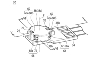
- the perspective view of the magnetic sensor unit of an Example is shown.
- the disassembled perspective view of the magnetic sensor unit of an Example is shown.
- the top view of the rotation part of the magnetic sensor unit of an Example is shown.
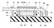
- 5 is a cross-sectional view taken along line VV in FIGS. Sectional drawing in the VI-VI line
- the cover has a through hole, and a pair of first snap fit structures are inserted into the through hole.
- the inner surface of the through hole functions as a deformation restricting portion. Further, according to this structure, it is possible to visually recognize the snap-fit structure from the outside of the cover, so that the assembly of the fuel level detection device is facilitated.
- the cover and the holder are provided with a second snap-fit structure for fixing them to each other.
- the cover can be easily fixed to the holder.
- a force acts on the arm in a direction away from the first snap fit structure
- a force acts on the cover in a direction away from the holder.
- force acts on the second snap-fit structure.
- the force applied to the second snap fit structure is not so large. For this reason, it is suppressed that a 2nd snap fit structure removes.
- a fuel pump module 10 shown in FIG. 1 is a unit for supplying fuel in a fuel tank 4 of a vehicle such as an automobile to an internal combustion engine (not shown).
- the fuel pump module 10 includes a fuel pump unit 12 and a fuel level detection device 20.
- the fuel pump unit 12 is accommodated in the fuel tank 4.
- the fuel pump unit 12 is attached to a set plate 6 that closes the opening of the fuel tank 4.
- the fuel pump unit 12 sucks the fuel in the fuel tank 4 into the fuel pump unit 12, boosts the fuel, and discharges the fuel outside the fuel pump unit 12.
- the fuel discharged from the fuel pump unit 12 is supplied from the discharge port 14 to an internal combustion engine (not shown).
- the fuel level detection device 20 includes a float 22, an arm 24, a magnetic sensor unit 30, and electric wires 54a to 54c.
- the float 22 floats on the fuel in the fuel tank 4 and moves in the vertical direction according to the liquid level of the fuel.
- the float 22 is rotatably attached to the tip of the arm 24.
- the base end of the arm 24 is rotatably supported by the magnetic sensor unit 30.
- the arm 24 swings and rotates with respect to the fuel pump unit 12. That is, the arm 24 converts the vertical movement of the float 22 into a rotational motion.
- the arm 24 is made of a metal having resistance to fuel, such as stainless steel, and is formed in a cylindrical rod shape.
- the magnetic sensor unit 30 supports the arm 24 rotatably.
- the magnetic sensor unit 30 detects the rotation angle of the arm 24.
- the magnetic sensor unit 30 includes a body 34, a holder 36, a cover 38, and a permanent magnet 44. 2 to 5, a part of the float 22 and the arm 24 on the float 22 side is omitted. Further, in FIG. 5, the cross section of the holder 36 is shown by mesh hatching, and the cross section of the cover 38 is shown by dot hatching.
- the body 34 is fixed to the outer wall of the fuel pump unit 12.
- the body 34 is made of resin.
- the body 34 includes a cylindrical portion 42.
- the cylindrical portion 42 has a cylindrical shape with the rotation axis X of the arm 24 as the central axis.
- a holder 36 is attached to the cylindrical portion 42.
- the body 34 incorporates a fuel level sensor 48.
- the fuel level sensor 48 is disposed on the rotation axis X.
- the fuel level sensor 48 is a Hall element configured by a semiconductor chip.
- the fuel level sensor 48 detects the direction of the magnetic field passing through itself.
- the fuel level sensor 48 may be constituted by other magnetic detection elements such as MRE (MagnetMagnResistive Element (magnetic resistance element)).
- MRE MagneticMagnetMagnResistive Element (magnetic resistance element)
- the fuel level sensor 48 is connected to the electric wires 54a to 54c shown in FIG.
- the fuel level sensor 48 outputs a signal indicating the direction of the magnetic field to the electric wire 54b.
- the output signal of the fuel level sensor 48 is transmitted to a fuel gauge outside the fuel tank 4.
- the holder 36 is rotatably supported by the cylindrical portion 42 of the body 34.
- the holder 36 can rotate with respect to the body 34 about the rotation axis X.
- the holder 36 has a first snap-fit structure 60 for holding the arm 24.
- the holder 36 has an accommodation hole 36 b for accommodating the proximal end of the arm 24.
- the holder 36 has a second snap fit structure 68 (more specifically, a protrusion 68a constituting a part of the second snap fit structure 68) for fixing the cover 38.
- the arm 24 is bent in an L shape at a bent portion 24 b in the vicinity of the base end 24 a opposite to the float 22. A portion of the arm 24 closer to the base end 24 a than the bent portion 24 b is inserted into the accommodation hole 36 b of the holder 36. As shown in FIG. 5, the main part of the arm 24 (the part closer to the float 22 than the bent part 24 b) is placed on the bottom 36 a of the holder 36. As shown in FIGS. 4 and 6, two first snap-fit structures 60 are provided on the bottom 36a. Each first snap fit structure 60 includes a pair of support portions 60a and 60b.
- the support portions 60a and 60b extend upward from the bottom portion 36a.
- “upper side” means a direction from the bottom 36 a toward the arm 24 on the surface where the bottom 36 a and the arm 24 are in contact with each other.
- “upper” is used in the same meaning.
- the support parts 60a and 60b have columnar parts 61a and 61b extending upward from the bottom part 36a, and claw parts 62a and 62b provided at the upper ends of the columnar parts 61a and 61b.
- a space is provided between the columnar part 61a and the columnar part 61b.
- interval between the columnar part 61a and the columnar part 61b is called the 1st space
- FIG. Claw portions 62a and 62b are provided at the upper ends of the columnar portions 61a and 61b.
- claw part 62a is provided in the surface inside the support part 60a (space
- claw part 62b is provided in the surface inside the support part 60b (space
- claw part 62b protrudes in the support part 60a side rather than the columnar part 61b.
- the claw portion 62a and the claw portion 62b face each other.
- a space is provided between the claw portion 62a and the claw portion 62b.
- claw part 62b is called the 2nd space
- the second spacing part 64 is located above the first spacing part 63.
- the width of the second spacing portion 64 is narrower than the width of the first spacing portion 63.
- the arm 24 is accommodated in the first spacing portion 63.
- the width of the first spacing portion 63 is the same as or slightly larger than the width (diameter) of the arm 24.
- the width of the second spacing portion 64 is smaller than the width (diameter) of the arm 24. For this reason, the claw portion 62 a and the claw portion 62 b are in contact with the arm 24 from above.
- the arm 24 is held in a state surrounded by the claw portions 62a and 62b, the columnar portions 61a and 61b, and the bottom portion 36a. For this reason, the arm 24 is fixed to the holder 36 in the first snap-fit structure 60. In each of the two first snap-fit structures 60 of the holder 36, the arm 24 is fixed as described above. Since the arm 24 is thus fixed to the holder 36, the arm 24 can rotate around the rotation axis X together with the holder 36.
- the base end 24a of the arm 24 is inserted into the accommodation hole 36b.
- the arm 24 is pressed from the upper side of the claw portions 62a and 62b toward the bottom portion 36a.
- the arm 24 comes into contact with the claw portions 62a and 62b, and the support portions 60a and 60b are pushed by the arm 24.
- the support portions 60a and 60b (more specifically, the columnar portions 61a and 61b) bend in a direction away from each other, and the width of the second interval portion 64 is increased. For this reason, the arm 24 enters the second interval portion 64.
- the arm 24 When the arm 24 is further moved to the bottom 36 a side, the arm 24 enters the first interval portion 63. Then, the support portions 60a and 60b return to their original positions (postures), and the width of the second interval portion 64 becomes narrow. As a result, as shown in FIG. 6, the arm 24 is fixed to each first snap-fit structure 60.
- a recess 36 c is provided in the center of the holder 36.
- the permanent magnet 44 is fixed to the holder 36 in the recess 36c. For this reason, when the arm 24 rotates, the permanent magnet 44 rotates around the rotation axis X.
- the permanent magnet 44 has an S pole and an N pole polarized in a direction orthogonal to the rotation axis X.
- the direction of the magnetic field passing through the fuel level sensor 48 shown in FIG. 5 changes. Therefore, the output signal of the fuel level sensor 48 changes according to the rotation angle of the permanent magnet 44.
- the rotation angle of the permanent magnet 44 represents the rotation angle of the arm 24.
- the rotation angle of the arm 24 corresponds to the vertical position of the float 22 (ie, the fuel level). Therefore, the output signal of the fuel level sensor 48 represents the fuel level.
- protrusions 68 a are provided on the outer peripheral surface of the holder 36.
- the cover 38 is fixed to the holder 36.
- the cover 38 has a top plate 38a and a side wall 38b extending downward from the top plate 38a.
- the top plate 38 a has a flat plate shape and covers the upper portion of the holder 36.
- the arm 24 is disposed between the top plate 38 a and the holder 36.
- the side wall 38 b has a cylindrical shape and covers the outer peripheral surface of the holder 36.
- the two top holes 38 are provided in the top plate 38a.
- Each through-hole 70 penetrates the top plate 38a from the upper surface to the lower surface.
- Each through-hole 70 has a rectangular shape.
- a regulating wall 71 extending downward from the top plate 38 a is provided along the outline of the through hole 70.
- the upper end portions of the first snap fit structure 60 that is, the upper end portions of the support portion 60a and the support portion 60b) are inserted into the respective through holes 70.
- a part of the regulating wall 71 is disposed at a position facing the surface on the opposite side of the spacing parts 63 and 64 of the support part 60a.
- Another part of the restriction wall 71 is disposed at a position facing the surface of the support portion 60b opposite to the interval portions 63 and 64.
- the interval W1 between the restriction wall 71 and the support portion 60a and the interval W2 between the restriction wall 71 and the support portion 60b are extremely small. More specifically, the interval W1 is smaller than 1 ⁇ 2 of the difference between the diameter of the arm 24 and the width of the second interval portion 64.
- the interval W2 is smaller than 1 ⁇ 2 of the difference between the diameter of the arm 24 and the width of the second interval portion 64.
- the width of the second spacing portion 64 does not become larger than the diameter of the arm 24.
- the restriction wall 71 prevents the arm 24 from coming off the first snap fit structure 60 by restricting the bending of the support portions 60 a and 60 b.
- each through-hole 72 penetrates the side wall 38b from the outer peripheral surface to the inner peripheral surface.
- Each through-hole 72 has a rectangular shape.
- a projection 68 a of the holder 36 is inserted into each through hole 72.
- the protrusion 68 a is in contact with the side wall 38 b of the cover 38 from above in the through hole 72.
- a second snap fit structure 68 is configured by the through hole 72 of the cover 38 and the protrusion 68 a of the holder 36.
- the cover 38 when attaching the cover 38 to the holder 36 in the manufacturing process of the fuel level detection device 20, the cover 38 is pressed toward the holder 36 so that the holder 36 is accommodated inside the cover 38. At this time, the positions of the protrusions 68a of the holder 36 are aligned with the positions of the through holes 72 of the cover 38.
- the protrusion 68 a of the holder 36 comes into contact with the inner peripheral surface of the side wall 38 b of the cover 38 (more specifically, the side wall 38 b of the portion located below the through hole 72). . If the cover 38 is moved toward the holder 36 as it is, the protrusion 68a slides on the inner peripheral surface of the side wall 38b.
- the protrusion 68a bends to the inner peripheral side. For this reason, the cover 38 can be further moved toward the holder 36. When the cover 38 is further moved toward the holder 36, the protrusion 68 a is inserted into the through hole 72. Then, the protrusion 68a returns to the original posture. For this reason, the protrusion 68a contacts the side wall 38b in the through hole 72 from above. As a result, the cover 38 is fixed to the holder 36. Further, by attaching the cover 38 as described above, the restriction wall 71 of the cover 38 is inserted at a position facing the support portions 60a and 60b as shown in FIG.
- a force may be applied to the arm 24 in a direction away from the first snap fit structure 60 due to vibration or impact. That is, in FIG. 6, a force may be applied to the arm 24 in a direction from the first spacing portion 63 toward the second spacing portion 64.
- a force is applied to the claw portions 62a and 62b in a direction in which the second interval portion 64 is expanded.
- the support portions 60a and 60b try to bend in the direction in which the second interval portion is expanded.
- the restriction wall 71 of the cover 38 is disposed at a position facing the surface of the support portions 60a, 60b opposite to the claw portions 62a, 62b.
- the force is also applied to the cover 38 via the holder 36.
- a force is applied to the cover 38 in a direction away from the holder 36. Since the cover 38 is fixed to the holder 36 by the second snap-fit structure 68, a force is applied to the second snap-fit structure 68 in this case.
- the second snap fit structure 68 is removed, the cover 38 is removed from the holder 36, and the restriction wall 71 is moved from a position facing the support portions 60a and 60b. In this case, the bending of the support portions 60a and 60b cannot be restricted by the restriction wall 71.
- the second snap-fit structure 68 is not in direct contact with the arm 24 and is disposed at a position away from the arm 24. For this reason, the force applied to the second snap fit structure 68 is small. For this reason, it is prevented that the 2nd snap fit structure 68 comes off.
- both the first snap fit structure 60 and the second snap fit structure 68 are difficult to come off, thereby preventing the arm 24 from coming off the holder 36.
- the assembly of the fuel level detection device 20 is facilitated by fixing the arm 24, the holder 36 and the cover 38 to each other by the first snap fit structure 60 and the second snap fit structure 68 in this way. For this reason, it becomes possible to manufacture the fuel liquid level detection apparatus 20 efficiently.
- the cover 38 is provided with the through hole 70, and the bending of the support portions 60 a and 60 b is restricted by the restriction wall 71 extending along the through hole 70.
- the inner surface of the through hole 70 functions as a member that restricts the bending of the support portions 60a and 60b.
- the fuel liquid level detection device 20 of the embodiment has been described above.
- the base end of the arm 24 is bent in an L shape.
- the base end of the arm 24 may have any shape.
- the support portions 60a and 60b on both sides of the first snap fit structure 60 have flexibility.
- only one of the support portions 60a and 60b may have flexibility, and the other may not have flexibility.
- only one of the support portions 60a and 60b may have a claw portion.
Landscapes
- Physics & Mathematics (AREA)
- Fluid Mechanics (AREA)
- General Physics & Mathematics (AREA)
- Level Indicators Using A Float (AREA)
Abstract
提供される燃料液位検出装置は、回転可能に支持されているホルダと、ホルダに固定されているアームと、アームを覆っている状態でホルダに固定されているカバーと、ホルダの外部でアームに接続されているフロートを有している。ホルダが、底部と第1スナップフィット構造を有している。第1スナップフィット構造が、底部上に間隔を開けて配置されている一対の支持部を有している。一対の支持部の間に、アームを収容している第1間隔部と、第1間隔部の上部に配置されているとともに第1間隔部内のアームの幅よりも狭い第2間隔部が設けられている。カバーが、一対の支持部の少なくとも一方の外側の表面に対向する位置に配置されている変形規制部を有している。
Description
本明細書に開示の技術は、燃料タンク内の燃料の液位を検出する燃料液位検出装置に関する。
特開2013-242174号公報に、ボディ(本体部)と、ホルダと、アームと、カバーと、フロートを有する燃料液位検出装置が開示されている。ボディは、燃料タンク内に固定される。ホルダは、ボディに対して回転可能に支持されている。アームは、ホルダに固定されている。カバーは、アームを覆っている状態でホルダに固定されている。アームの一部は、ホルダから外部に伸びている。フロートは、ホルダの外部でアームに接続されている。フロートは、燃料タンク内の燃料に浮遊する。燃料の液位が変化すると、フロートが上下動する。すると、アームがカバー及びホルダと共にボディに対して回転する。アームの回転角度を検出することで、燃料の液位が検出される。
特開2013-242174号公報の燃料液位検出装置では、アームがホルダに対してスナップフィット構造によって固定されている。なお、本明細書において、スナップフィット構造とは、一方の部材を他方の部材に向かって押し付ける過程において前記他方の部材の一部が弾性変形により撓み、前記一方の部材を前記他方の部材に対して所定の位置まで押し込むと、撓んでいた部分が元の形状に復帰してその位置で両部材が互いに固定される構造を意味する。スナップフィット構造を用いることで、アームをホルダに対して簡単に固定することが可能となり、燃料液位検出装置の組み立てが容易となる。
燃料液位検出装置の使用中に、スナップフィット構造の保持力が低下する場合がある。例えば、燃料タンク内の温度変化によって、スナップフィット構造の保持力が低下する場合がある。また、ホルダは燃料中に浸漬されるので、スナップフィット構造が燃料を吸収して膨潤することでスナップフィット構造の保持力が低下する場合がある。このため、燃料液位検出装置の使用中に振動や衝撃が加わることによって、アームがスナップフィット構造から外れるおそれがある。スナップフィット構造の保持力の低下を考慮して、予めスナップフィット構造を硬くし、保持力を高くすることも考えられる。しかしながら、スナップフィット構造を硬くすると、スナップフィット構造の可撓性が低下するので、燃料液位検出装置の組み立て効率が低下する。また、スナップフィット構造の可撓性が低下すると、燃料液位検出装置の組み立て時にスナップフィット構造が塑性変形し、保持力が極端に低下する可能性もある。
したがって、本明細書では、スナップフィット構造の可撓性を維持しながら、スナップフィット構造の保持力の低下を抑制することが可能な新たな技術を提供する。
本明細書で開示される燃料液位検出装置は、燃料タンク内の燃料の液位を検出する。この燃料液位検出装置は、前記燃料タンク内に固定されるボディと、前記ボディによって回転可能に支持されているホルダと、前記ホルダに固定されているアームと、前記アームを覆っている状態で前記ホルダに固定されているカバーと、前記ホルダの外部で前記アームに接続されているフロートを有している。前記ホルダが、底部と第1スナップフィット構造を有している。前記第1スナップフィット構造が、前記底部上に間隔を開けて配置されている一対の支持部を有している。前記一対の支持部の間に、前記アームを収容している第1間隔部と、前記第1間隔部の上部に配置されているとともに前記第1間隔部内の前記アームの幅よりも狭い第2間隔部が設けられている。前記カバーが、前記一対の支持部の少なくとも一方の外側の表面に対向する位置に配置されている変形規制部を有している。
なお、上記の「第1間隔部の上部」は、第1間隔部に対して底部から離れる側(支持部の先端側)を意味する。また、上記の「外側の表面」は、一対の支持部の間の間隔部(第1間隔部及び第2間隔部)側の表面とは反対側の表面を意味する。
この燃料液位検出装置では、振動や衝撃によってアームに対して第1スナップフィット構造から外れる方向(すなわち、底部から離れる方向)に向かって力が作用すると、幅が狭い第2間隔部においてアームが一対の支持部に当接する。すると、一対の支持部に対して第2間隔部を拡げる方向に力が加わる。この力によって一対の支持部の少なくとも一方が第2間隔部の幅を広げる方向に撓もうとすると、その支持部がカバーの変形規制部に当接する。このため、第2間隔部の幅がそれ以上広くなることが防止され、アームが第1スナップフィット構造から外れることが防止される。この構造では、支持部が変形規制部に物理的に当接することで支持部の変形が規制されるので、第1スナップフィット構造の保持力の経時的な低下が生じ難い。また、この構造によれば、第1スナップフィット構造の可撓性を維持しながら、その保持力の低下を抑制することができる。
以下に説明する実施例の主要な特徴を列記する。なお、以下に記載する技術要素は、それぞれ独立した技術要素であって、単独であるいは各種の組合せによって技術的有用性を発揮するものである。
(特徴1)カバーが貫通孔を有しており、貫通孔内に一対の第1スナップフィット構造が挿入されている。この構成によれば、貫通孔の内面が変形規制部として機能する。また、この構造によれば、カバーの外側からスナップフィット構造を視認することが可能であるので、燃料液位検出装置の組み立てが容易となる。
(特徴2)カバーとホルダに、これらを互いに固定する第2スナップフィット構造が設けられている。この構成によれば、カバーをホルダに対して容易に固定することができる。また、アームに対して第1スナップフィット構造から外れる方向に力が作用すると、カバーに対してホルダから外れる方向に力が作用する。このため、第2スナップフィット構造に対して力が作用する。しかしながら、第2スナップフィット構造に対してはアームから直接力が加わらないので、第2スナップフィット構造に加わる力はそれほど大きくない。このため、第2スナップフィット構造が外れることが抑制される。
図1に示す燃料ポンプモジュール10は、自動車等の車両の燃料タンク4内の燃料を、図示省略した内燃機関に供給するためのユニットである。
燃料ポンプモジュール10は、燃料ポンプユニット12と、燃料液位検出装置20と、を備える。燃料ポンプユニット12は、燃料タンク4内に収容されている。燃料ポンプユニット12は、燃料タンク4の開口を閉塞するセットプレート6に取付けられている。燃料ポンプユニット12は、燃料タンク4内の燃料を、燃料ポンプユニット12内に吸入し昇圧して、燃料ポンプユニット12外に吐出する。燃料ポンプユニット12から吐出された燃料は、吐出ポート14から、図示省略された内燃機関に供給される。
燃料液位検出装置20は、フロート22、アーム24、磁気センサユニット30、及び、電線54a~54cを備えている。フロート22は、燃料タンク4内の燃料に浮かんでおり、燃料の液面に応じて上下方向に運動する。フロート22は、アーム24の先端に回転自在に取り付けられている。アーム24の基端は、磁気センサユニット30に回転可能に支持されている。燃料タンク4内の燃料の液面に応じてフロート22が上下動すると、アーム24が燃料ポンプユニット12に対して揺動回転する。即ち、アーム24は、フロート22の上下動を回転運動に変換する。アーム24は、例えばステンレス等の燃料に対する耐性を有する金属で円柱の棒状に作製されている。
磁気センサユニット30は、アーム24を回転自在に支持している。磁気センサユニット30は、アーム24の回転角を検出する。図2~5に示すように、磁気センサユニット30は、ボディ34と、ホルダ36と、カバー38と、永久磁石44を備えている。なお、図2~5では、フロート22及びアーム24のフロート22側の一部が省略されている。また、図5では、ホルダ36の断面が網目模様のハッチングにより示されており、カバー38の断面がドットハッチングにより示されている。
図1に示すように、ボディ34は、燃料ポンプユニット12の外壁に固定されている。ボディ34は、樹脂により構成されている。図3、5に示すように、ボディ34は、円筒部42を備えている。円筒部42は、アーム24の回転軸Xを中心軸とする円筒形状を有する。円筒部42に、ホルダ36が取り付けられている。
図5に示すように、ボディ34は、燃料液位センサ48を内蔵している。燃料液位センサ48は、回転軸X上に配置されている。燃料液位センサ48は、半導体チップによって構成されたホール素子である。燃料液位センサ48は、自身を通過する磁界の向きを検出する。なお、MRE(Magnet Resistive Element(磁気抵抗素子))等の他の磁気検出素子によって燃料液位センサ48が構成されていてもよい。燃料液位センサ48は、図示しない配線によって図1に示す電線54a~54cに接続されている。燃料液位センサ48は、磁界の向きを示す信号を電線54bに出力する。燃料液位センサ48の出力信号は、燃料タンク4の外部の燃料計に送信される。
ホルダ36は、ボディ34の円筒部42に回転可能に支持されている。ホルダ36は、回転軸Xを中心にボディ34に対して回転することができる。図2~4に示すように、ホルダ36は、アーム24を保持するための第1スナップフィット構造60を有している。また、ホルダ36は、アーム24の基端を収容するための収容孔36bを有している。また、ホルダ36は、カバー38を固定するための第2スナップフィット構造68(より詳細には、第2スナップフィット構造68の一部を構成する突起部68a)を有している。
図3、5に示すように、アーム24は、フロート22とは反対側の基端24aの近傍の屈曲部24bにおいて、L字状に屈曲されている。アーム24の屈曲部24bよりも基端24a側の部分は、ホルダ36の収容孔36b内に挿入されている。図5に示すように、アーム24の主要部(屈曲部24bよりもフロート22側の部分)は、ホルダ36の底部36a上に載置されている。図4、6に示すように、底部36a上に、2つの第1スナップフィット構造60が設けられている。各第1スナップフィット構造60は、一対の支持部60a、60bにより構成されている。各第1スナップフィット構造60の構造は略等しいので、以下では、図2、4のVI-VI線側の第1スナップフィット構造60について説明する。図6に示すように、支持部60a、60bは、底部36aから上側に伸びている。なお、ここでいう「上側」とは、底部36aとアーム24とが接している面において、底部36aからアーム24に向かう方向を意味する。以下の説明においても、「上」を同様の意味で用いる。支持部60a、60bは、底部36aから上側に伸びる柱状部61a、61bと、柱状部61a、61bの上端に設けられた爪部62a、62bを有している。柱状部61aと柱状部61bの間には、間隔が設けられている。以下では、柱状部61aと柱状部61bの間の間隔を、第1間隔部63という。柱状部61a、61bの上端に、爪部62a、62bが設けられている。爪部62aは支持部60aの内側(間隔部側)の表面に設けられている。爪部62aは、柱状部61aよりも支持部60b側に突出している。爪部62bは支持部60bの内側(間隔部側)の表面に設けられている。爪部62bは、柱状部61bよりも支持部60a側に突出している。爪部62aと爪部62bは互いに対向している。爪部62aと爪部62bの間には、間隔が設けられている。以下では、爪部62aと爪部62bの間の間隔を、第2間隔部64という。第2間隔部64は、第1間隔部63の上部に位置している。第2間隔部64の幅は、第1間隔部63の幅よりも狭い。第1間隔部63には、アーム24が収容されている。第1間隔部63の幅は、アーム24の幅(直径)と同じか、それよりもやや大きい。第2間隔部64の幅は、アーム24の幅(直径)よりも小さい。このため、爪部62aと爪部62bは、アーム24に対して上側から接している。アーム24は、爪部62a、62b、柱状部61a、61b及び底部36aによって囲まれた状態で保持されている。このため、第1スナップフィット構造60においてアーム24がホルダ36に固定されている。ホルダ36の2つの第1スナップフィット構造60のそれぞれにおいて、上記のようにアーム24が固定されている。このようにアーム24がホルダ36に固定されているので、アーム24はホルダ36と共に回転軸Xを中心に回転することができる。
なお、燃料液位検出装置20の製造工程においてアーム24をホルダ36に取り付ける際には、まず、アーム24の基端24aを収容孔36bに挿入する。次に、アーム24を、爪部62a、62bの上側から底部36aに向かって押し付ける。すると、アーム24が爪部62a、62bに当接し、アーム24によって支持部60a、60bが押される。すると、支持部60a、60b(より詳細には、柱状部61a、61b)が互いから離れる方向に撓み、第2間隔部64の幅が広がる。このため、アーム24が第2間隔部64内に進入する。アーム24をさらに底部36a側に移動させると、アーム24が第1間隔部63内に進入する。すると、支持部60a、60bが元の位置(姿勢)に戻り、第2間隔部64の幅が狭くなる。これによって、図6に示すように、アーム24が各第1スナップフィット構造60に固定される。
図3、5に示すように、ホルダ36の中央には、凹部36cが設けられている。永久磁石44は、凹部36c内でホルダ36に固定されている。このため、アーム24が回転すると、永久磁石44が回転軸Xを中心に回転する。永久磁石44は、回転軸Xと直交する方向に分極したS極とN極を有している。永久磁石44が回転軸Xを中心として回転すると、図5に示す燃料液位センサ48を通過する磁界の向きが変化する。したがって、永久磁石44の回転角度に応じて、燃料液位センサ48の出力信号が変化する。永久磁石44の回転角度は、アーム24の回転角度を表す。また、アーム24の回転角度は、フロート22の上下方向の位置(すなわち、燃料の液位)に対応する。したがって、燃料液位センサ48の出力信号は、燃料の液位を表す。
図2~4に示すように、ホルダ36の外周面には、4つの突起部68aが設けられている。
カバー38は、ホルダ36に固定されている。カバー38は、天板38aと、天板38aから下側に伸びる側壁38bを有している。天板38aは、平板形状を有しており、ホルダ36の上部を覆っている。天板38aとホルダ36の間に、アーム24が配置されている。側壁38bは、円筒形状を有しており、ホルダ36の外周面を覆っている。
天板38aには、2つの貫通孔70が設けられている。各貫通孔70は、天板38aを上面から下面まで貫通している。各貫通孔70は、矩形を有している。図6に示すように、貫通孔70の輪郭に沿って、天板38aから下方向に伸びる規制壁71が設けられている。各貫通孔70に、第1スナップフィット構造60の上端部(すなわち、支持部60aと支持部60bの上端部)が挿入されている。規制壁71の一部は、支持部60aの間隔部63、64とは反対側の表面に対向する位置に配置されている。規制壁71の別の一部は、支持部60bの間隔部63、64とは反対側の表面に対向する位置に配置されている。規制壁71と支持部60aの間の間隔W1、及び、規制壁71と支持部60bの間の間隔W2は極めて小さい。より具体的には、間隔W1は、アーム24の直径と第2間隔部64の幅の差の1/2よりも小さい。また、間隔W2は、アーム24の直径と第2間隔部64の幅の差の1/2よりも小さい。したがって、カバー38が取り付けられている状態では、規制壁71に接触する位置まで支持部60a、60bが撓んだとしても、第2間隔部64の幅がアーム24の直径よりも大きくならない。規制壁71は、支持部60a、60bの撓みを規制することで、アーム24が第1スナップフィット構造60から外れることを防止する。
図2~4に示すように、側壁38bには、4つの貫通孔72が設けられている。各貫通孔72は、側壁38bを外周面から内周面まで貫通している。各貫通孔72は、矩形を有している。各貫通孔72内に、ホルダ36の突起部68aが挿入されている。突起部68aは、貫通孔72内でカバー38の側壁38bに対して上側から接している。これによって、カバー38がホルダ36に固定されている。カバー38の貫通孔72とホルダ36の突起部68aによって、第2スナップフィット構造68が構成されている。
なお、燃料液位検出装置20の製造工程においてカバー38をホルダ36に取り付ける際には、カバー38の内側にホルダ36が収容されるようにして、カバー38をホルダ36に向かって押し付ける。このとき、ホルダ36の各突起部68aの位置とカバー38の各貫通孔72の位置とが一致するように位置を合わせる。カバー38をホルダ36に向かって押し付けると、ホルダ36の突起部68aがカバー38の側壁38b(より詳細には、貫通孔72の下側に位置する部分の側壁38b)の内周面に接触する。そのままカバー38をホルダ36に向かって移動させると、突起部68aが側壁38bの内周面と摺動する。このとき、突起部68aが内周側に撓む。このため、カバー38をホルダ36に向かってさらに移動させることができる。カバー38をホルダ36に向かってさらに移動させると、突起部68aが貫通孔72内に挿入される。すると、突起部68aが元の姿勢に戻る。このため、突起部68aが貫通孔72内で側壁38bに対して上側から接触する。これによって、カバー38がホルダ36に固定される。また、上記のようにカバー38を取り付けることで、カバー38の規制壁71が、図6に示すように、支持部60a、60bに対向する位置に挿入される。
燃料液位検出装置20の使用中に、振動や衝撃が加わることによってアーム24に第1スナップフィット構造60から外れる方向に力が加わることがある。すなわち、図6において、アーム24に対して第1間隔部63から第2間隔部64に向かう方向に力が加わることがある。このような力がアーム24に加わると、爪部62a、62bに対して、第2間隔部64を広げる方向に力が加わる。これによって、支持部60a、60bが第2間隔部を広げる方向に撓もうとする。しかしながら、支持部60a、60bの爪部62a、62bとは反対側の表面に対向する位置に、カバー38の規制壁71が配置されている。このため、支持部60a、60bがわずかに撓むと、支持部60a、60bが規制壁71に接触する。これによって、支持部60a、60bがそれ以上撓むことが防止される。このため、第2間隔部64の拡大が防止され、アーム24が第1スナップフィット構造60から外れることが防止される。
また、アーム24に上記の力が加わると、ホルダ36を介してカバー38に対しても力が加わる。カバー38には、ホルダ36から外れる方向に力が加わる。カバー38は第2スナップフィット構造68によってホルダ36に固定されているので、この場合には第2スナップフィット構造68に力が加わる。第2スナップフィット構造68が外れると、カバー38がホルダ36から外れ、規制壁71が支持部60a、60bに対向する位置から移動する。この場合、規制壁71によって支持部60a、60bの撓みを規制することができなくなる。しかしながら、第2スナップフィット構造68は、アーム24には直接接しておらず、アーム24から離れた位置に配置されている。このため、第2スナップフィット構造68に加わる力は小さい。このため、第2スナップフィット構造68が外れることが防止される。
以上に説明したように、本実施例の燃料液位検出装置20では、第1スナップフィット構造60と第2スナップフィット構造68が共に外れ難く、これによってアーム24がホルダ36から外れることが防止される。また、このように第1スナップフィット構造60と第2スナップフィット構造68によってアーム24、ホルダ36及びカバー38を互い固定することで、燃料液位検出装置20の組み立てが容易となる。このため、燃料液位検出装置20を効率的に製造することが可能となる。
また、本実施例の燃料液位検出装置20では、カバー38に貫通孔70が設けられており、貫通孔70に沿って伸びる規制壁71によって支持部60a、60bの撓みが規制される。言い換えると、貫通孔70の内面が、支持部60a、60bの撓みを規制する部材として機能する。この構成によれば、カバー38をホルダ36に取り付ける際に、外部から貫通孔70を介して支持部60a、60bを視認することができる。このため、カバー38をホルダ36に取り付けやすい。
以上、実施例の燃料液位検出装置20について説明した。なお、上記の実施例では、アーム24の基端がL字状に屈曲していたが、アーム24の基端の形状はどのような形状であってもよい。
また、上記の実施例では、第1スナップフィット構造60において、両側の支持部60a、60bが可撓性を有していた。しかしながら、支持部60a、60bのいずれか一方のみが可撓性を有しており、他方が可撓性を有していなくてもよい。この場合、可撓性を有する支持部に対してのみ、その撓みを規制する部分(例えば、規制壁71)をカバー38に設ければよい。また、支持部60a、60bのいずれか一方のみが爪部を有していてもよい。
以上、本発明の実施例について詳細に説明したが、これらは例示に過ぎず、特許請求の範囲を限定するものではない。特許請求の範囲に記載の技術には、以上に例示した具体例を様々に変形、変更したものが含まれる。また、本明細書または図面に説明した技術要素は、単独であるいは各種の組合せによって技術的有用性を発揮するものであり、出願時請求項記載の組合せに限定されるものではない。また、本明細書または図面に例示した技術は複数目的を同時に達成するものであり、そのうちの一つの目的を達成すること自体で技術的有用性を持つものである。
Claims (3)
- 燃料タンク内の燃料の液位を検出する燃料液位検出装置であって、
前記燃料タンク内に固定されるボディと、
前記ボディによって回転可能に支持されているホルダと、
前記ホルダに固定されているアームと、
前記アームを覆っている状態で前記ホルダに固定されているカバーと、
前記ホルダの外部で前記アームに接続されているフロート、
を有しており、
前記ホルダが、底部と第1スナップフィット構造を有しており、
前記第1スナップフィット構造が、前記底部上に間隔を開けて配置されている一対の支持部を有しており、
前記一対の支持部の間に、前記アームを収容している第1間隔部と、前記第1間隔部の上部に配置されているとともに前記第1間隔部内の前記アームの幅よりも狭い第2間隔部が設けられており、
前記カバーが、前記一対の支持部の少なくとも一方の外側の表面に対向する位置に配置されている変形規制部を有している、
燃料液位検出装置。 - 前記カバーが貫通孔を有しており、
前記貫通孔内に前記第1スナップフィット構造が挿入されている、
請求項1の燃料液位検出装置。 - 前記カバーと前記ホルダに、これらを互いに固定する第2スナップフィット構造が設けられている請求項1または2の燃料液位検出装置。
Priority Applications (2)
| Application Number | Priority Date | Filing Date | Title |
|---|---|---|---|
| US16/309,680 US10962401B2 (en) | 2016-06-14 | 2017-03-15 | Fuel level detection device |
| CN201780036314.9A CN109313062B (zh) | 2016-06-14 | 2017-03-15 | 燃料液位检测装置 |
Applications Claiming Priority (2)
| Application Number | Priority Date | Filing Date | Title |
|---|---|---|---|
| JP2016118030A JP6534638B2 (ja) | 2016-06-14 | 2016-06-14 | 燃料液位検出装置 |
| JP2016-118030 | 2016-06-14 |
Publications (1)
| Publication Number | Publication Date |
|---|---|
| WO2017217048A1 true WO2017217048A1 (ja) | 2017-12-21 |
Family
ID=60663109
Family Applications (1)
| Application Number | Title | Priority Date | Filing Date |
|---|---|---|---|
| PCT/JP2017/010484 Ceased WO2017217048A1 (ja) | 2016-06-14 | 2017-03-15 | 燃料液位検出装置 |
Country Status (4)
| Country | Link |
|---|---|
| US (1) | US10962401B2 (ja) |
| JP (1) | JP6534638B2 (ja) |
| CN (1) | CN109313062B (ja) |
| WO (1) | WO2017217048A1 (ja) |
Families Citing this family (4)
| Publication number | Priority date | Publication date | Assignee | Title |
|---|---|---|---|---|
| JP6668225B2 (ja) * | 2016-12-06 | 2020-03-18 | 愛三工業株式会社 | 液面検出装置 |
| US11738990B2 (en) | 2021-06-16 | 2023-08-29 | Whitecap Industries, Inc. | Ullage float assembly for fuel tank and methods of use |
| JP7384888B2 (ja) * | 2021-12-09 | 2023-11-21 | 矢崎総業株式会社 | 液位検出装置 |
| US12583313B2 (en) | 2024-08-20 | 2026-03-24 | Whitecap Industries, Inc. | Combined fuel level sending unit and fuel fill limit vent valve |
Citations (4)
| Publication number | Priority date | Publication date | Assignee | Title |
|---|---|---|---|---|
| US20050103103A1 (en) * | 2003-11-17 | 2005-05-19 | Nartron Corporation | Fuel level sensor |
| JP2013096754A (ja) * | 2011-10-28 | 2013-05-20 | Denso Corp | 液面検出装置の取付構造 |
| JP2015210153A (ja) * | 2014-04-25 | 2015-11-24 | 愛三工業株式会社 | 液面検出装置 |
| US20160109279A1 (en) * | 2014-08-22 | 2016-04-21 | Ksr Ip Holdings Llc. | Inductive sensor |
Family Cites Families (7)
| Publication number | Priority date | Publication date | Assignee | Title |
|---|---|---|---|---|
| AU2003281795A1 (en) * | 2002-07-31 | 2004-02-23 | Nippon Seiki Co., Ltd. | Fuel tank cover body |
| JP5152679B2 (ja) * | 2009-03-27 | 2013-02-27 | 日本精機株式会社 | 液面検出装置 |
| KR101181233B1 (ko) * | 2010-05-24 | 2012-09-11 | 현담산업 주식회사 | 비접촉식 연료센더의 홀더와 그립퍼의 결합구조 |
| JP5966607B2 (ja) | 2012-05-18 | 2016-08-10 | 日本精機株式会社 | 液面検出装置 |
| CN202793520U (zh) | 2012-08-01 | 2013-03-13 | 李道庆 | 液面高度感测装置 |
| DE102013215015A1 (de) * | 2013-07-31 | 2015-02-05 | Robert Bosch Gmbh | Messvorrichtung für Füllstand eines Behälters |
| JP2015102501A (ja) | 2013-11-27 | 2015-06-04 | 日本精機株式会社 | 液面検出装置 |
-
2016
- 2016-06-14 JP JP2016118030A patent/JP6534638B2/ja active Active
-
2017
- 2017-03-15 CN CN201780036314.9A patent/CN109313062B/zh active Active
- 2017-03-15 US US16/309,680 patent/US10962401B2/en active Active
- 2017-03-15 WO PCT/JP2017/010484 patent/WO2017217048A1/ja not_active Ceased
Patent Citations (4)
| Publication number | Priority date | Publication date | Assignee | Title |
|---|---|---|---|---|
| US20050103103A1 (en) * | 2003-11-17 | 2005-05-19 | Nartron Corporation | Fuel level sensor |
| JP2013096754A (ja) * | 2011-10-28 | 2013-05-20 | Denso Corp | 液面検出装置の取付構造 |
| JP2015210153A (ja) * | 2014-04-25 | 2015-11-24 | 愛三工業株式会社 | 液面検出装置 |
| US20160109279A1 (en) * | 2014-08-22 | 2016-04-21 | Ksr Ip Holdings Llc. | Inductive sensor |
Also Published As
| Publication number | Publication date |
|---|---|
| JP2017223504A (ja) | 2017-12-21 |
| US10962401B2 (en) | 2021-03-30 |
| US20190170561A1 (en) | 2019-06-06 |
| JP6534638B2 (ja) | 2019-06-26 |
| CN109313062B (zh) | 2021-01-08 |
| CN109313062A (zh) | 2019-02-05 |
Similar Documents
| Publication | Publication Date | Title |
|---|---|---|
| CN105680201B (zh) | 端子模块 | |
| JP6534638B2 (ja) | 燃料液位検出装置 | |
| CN106164826B (zh) | 电子设备的振动产生装置 | |
| CN108431627B (zh) | 超声波传感器 | |
| CN109072831B (zh) | 燃料供给装置 | |
| JP6123521B2 (ja) | 液面検出装置 | |
| JP6684958B2 (ja) | 固定導電板と弾性導電板を有する電子装置 | |
| EP1528376B1 (en) | Fuel tank cover body | |
| US9267610B2 (en) | Hydraulic pressure control device | |
| JP5953253B2 (ja) | センサ及びセンサの製造方法 | |
| JP5812187B2 (ja) | 接続端子およびこれを用いたコネクタ | |
| US20190137319A1 (en) | Fuel level detection device and production method therefor | |
| JP2011150807A (ja) | コネクタ | |
| JP6687576B2 (ja) | グロメット | |
| JP2014533878A (ja) | 電子回路基板を受け入れるか又は取り囲むハウジングにおいて複数の接触要素に接触する電子回路基板を設置する方法及びハウジング | |
| JP2009210428A (ja) | 超音波センサ装置 | |
| JP5146901B2 (ja) | 回転検出装置 | |
| JP2016057099A (ja) | 液面検出装置 | |
| JP6098833B2 (ja) | 電子部品接続用端子及びそれを使用した電子部品の取付け構造 | |
| CN111164387A (zh) | 用于传感器安装的弹簧夹 | |
| JP2010145137A5 (ja) | ||
| JP2009268241A (ja) | リニア駆動型超音波モータ | |
| JP2009058376A (ja) | 液面検出装置 | |
| JP6179768B2 (ja) | 液面検出装置 | |
| JP2025058557A (ja) | コネクタユニット |
Legal Events
| Date | Code | Title | Description |
|---|---|---|---|
| 121 | Ep: the epo has been informed by wipo that ep was designated in this application |
Ref document number: 17812954 Country of ref document: EP Kind code of ref document: A1 |
|
| NENP | Non-entry into the national phase |
Ref country code: DE |
|
| 122 | Ep: pct application non-entry in european phase |
Ref document number: 17812954 Country of ref document: EP Kind code of ref document: A1 |