WO2017213105A1 - Catalyseur de purification de gaz d'échappement - Google Patents
Catalyseur de purification de gaz d'échappement Download PDFInfo
- Publication number
- WO2017213105A1 WO2017213105A1 PCT/JP2017/020879 JP2017020879W WO2017213105A1 WO 2017213105 A1 WO2017213105 A1 WO 2017213105A1 JP 2017020879 W JP2017020879 W JP 2017020879W WO 2017213105 A1 WO2017213105 A1 WO 2017213105A1
- Authority
- WO
- WIPO (PCT)
- Prior art keywords
- layer
- exhaust gas
- lower layer
- catalyst
- upper layer
- Prior art date
Links
- 239000003054 catalyst Substances 0.000 title claims abstract description 113
- 238000000746 purification Methods 0.000 claims description 55
- 239000000758 substrate Substances 0.000 claims description 43
- 239000002131 composite material Substances 0.000 claims description 35
- 239000000463 material Substances 0.000 claims description 25
- MCMNRKCIXSYSNV-UHFFFAOYSA-N ZrO2 Inorganic materials O=[Zr]=O MCMNRKCIXSYSNV-UHFFFAOYSA-N 0.000 claims description 18
- 229910052684 Cerium Inorganic materials 0.000 claims description 14
- 238000002485 combustion reaction Methods 0.000 claims description 6
- 229910052703 rhodium Inorganic materials 0.000 claims description 6
- 239000010410 layer Substances 0.000 abstract description 304
- 239000011247 coating layer Substances 0.000 abstract description 4
- 239000007789 gas Substances 0.000 description 76
- KDLHZDBZIXYQEI-UHFFFAOYSA-N palladium Substances [Pd] KDLHZDBZIXYQEI-UHFFFAOYSA-N 0.000 description 65
- 239000002002 slurry Substances 0.000 description 35
- 239000010948 rhodium Substances 0.000 description 27
- 238000000034 method Methods 0.000 description 21
- QVGXLLKOCUKJST-UHFFFAOYSA-N atomic oxygen Chemical compound [O] QVGXLLKOCUKJST-UHFFFAOYSA-N 0.000 description 17
- 229910052760 oxygen Inorganic materials 0.000 description 17
- 239000001301 oxygen Substances 0.000 description 17
- 229910000510 noble metal Inorganic materials 0.000 description 15
- 239000000446 fuel Substances 0.000 description 11
- 229910018072 Al 2 O 3 Inorganic materials 0.000 description 10
- PNEYBMLMFCGWSK-UHFFFAOYSA-N aluminium oxide Inorganic materials [O-2].[O-2].[O-2].[Al+3].[Al+3] PNEYBMLMFCGWSK-UHFFFAOYSA-N 0.000 description 10
- TZCXTZWJZNENPQ-UHFFFAOYSA-L barium sulfate Chemical compound [Ba+2].[O-]S([O-])(=O)=O TZCXTZWJZNENPQ-UHFFFAOYSA-L 0.000 description 10
- 230000000052 comparative effect Effects 0.000 description 10
- 230000003197 catalytic effect Effects 0.000 description 9
- 238000002156 mixing Methods 0.000 description 9
- GWXLDORMOJMVQZ-UHFFFAOYSA-N cerium Chemical compound [Ce] GWXLDORMOJMVQZ-UHFFFAOYSA-N 0.000 description 8
- 239000011248 coating agent Substances 0.000 description 7
- 238000000576 coating method Methods 0.000 description 7
- 229910052763 palladium Inorganic materials 0.000 description 7
- 230000000694 effects Effects 0.000 description 6
- 229910052746 lanthanum Inorganic materials 0.000 description 6
- FZLIPJUXYLNCLC-UHFFFAOYSA-N lanthanum atom Chemical compound [La] FZLIPJUXYLNCLC-UHFFFAOYSA-N 0.000 description 6
- 238000000465 moulding Methods 0.000 description 6
- BASFCYQUMIYNBI-UHFFFAOYSA-N platinum Substances [Pt] BASFCYQUMIYNBI-UHFFFAOYSA-N 0.000 description 6
- 239000000843 powder Substances 0.000 description 6
- 229910052761 rare earth metal Inorganic materials 0.000 description 6
- 238000012360 testing method Methods 0.000 description 6
- 229910052727 yttrium Inorganic materials 0.000 description 6
- VWQVUPCCIRVNHF-UHFFFAOYSA-N yttrium atom Chemical compound [Y] VWQVUPCCIRVNHF-UHFFFAOYSA-N 0.000 description 6
- 229910052788 barium Inorganic materials 0.000 description 5
- DSAJWYNOEDNPEQ-UHFFFAOYSA-N barium atom Chemical compound [Ba] DSAJWYNOEDNPEQ-UHFFFAOYSA-N 0.000 description 5
- XLYOFNOQVPJJNP-UHFFFAOYSA-N water Substances O XLYOFNOQVPJJNP-UHFFFAOYSA-N 0.000 description 5
- CETPSERCERDGAM-UHFFFAOYSA-N ceric oxide Chemical compound O=[Ce]=O CETPSERCERDGAM-UHFFFAOYSA-N 0.000 description 4
- 229910000422 cerium(IV) oxide Inorganic materials 0.000 description 4
- 238000010586 diagram Methods 0.000 description 4
- 231100000572 poisoning Toxicity 0.000 description 4
- 230000000607 poisoning effect Effects 0.000 description 4
- 239000000126 substance Substances 0.000 description 4
- OYPRJOBELJOOCE-UHFFFAOYSA-N Calcium Chemical compound [Ca] OYPRJOBELJOOCE-UHFFFAOYSA-N 0.000 description 3
- 229910002651 NO3 Inorganic materials 0.000 description 3
- NHNBFGGVMKEFGY-UHFFFAOYSA-N Nitrate Chemical compound [O-][N+]([O-])=O NHNBFGGVMKEFGY-UHFFFAOYSA-N 0.000 description 3
- KJTLSVCANCCWHF-UHFFFAOYSA-N Ruthenium Chemical compound [Ru] KJTLSVCANCCWHF-UHFFFAOYSA-N 0.000 description 3
- 229910052791 calcium Inorganic materials 0.000 description 3
- 239000011575 calcium Substances 0.000 description 3
- 230000001771 impaired effect Effects 0.000 description 3
- 229910052809 inorganic oxide Inorganic materials 0.000 description 3
- 229910052741 iridium Inorganic materials 0.000 description 3
- GKOZUEZYRPOHIO-UHFFFAOYSA-N iridium atom Chemical compound [Ir] GKOZUEZYRPOHIO-UHFFFAOYSA-N 0.000 description 3
- 229910044991 metal oxide Inorganic materials 0.000 description 3
- 150000004706 metal oxides Chemical class 0.000 description 3
- 239000000203 mixture Substances 0.000 description 3
- 229910052762 osmium Inorganic materials 0.000 description 3
- SYQBFIAQOQZEGI-UHFFFAOYSA-N osmium atom Chemical compound [Os] SYQBFIAQOQZEGI-UHFFFAOYSA-N 0.000 description 3
- TWNQGVIAIRXVLR-UHFFFAOYSA-N oxo(oxoalumanyloxy)alumane Chemical compound O=[Al]O[Al]=O TWNQGVIAIRXVLR-UHFFFAOYSA-N 0.000 description 3
- RVTZCBVAJQQJTK-UHFFFAOYSA-N oxygen(2-);zirconium(4+) Chemical compound [O-2].[O-2].[Zr+4] RVTZCBVAJQQJTK-UHFFFAOYSA-N 0.000 description 3
- 229910052697 platinum Inorganic materials 0.000 description 3
- 229910052707 ruthenium Inorganic materials 0.000 description 3
- 239000006104 solid solution Substances 0.000 description 3
- 239000003381 stabilizer Substances 0.000 description 3
- 229910052723 transition metal Inorganic materials 0.000 description 3
- 229910001928 zirconium oxide Inorganic materials 0.000 description 3
- 239000004215 Carbon black (E152) Substances 0.000 description 2
- 239000011230 binding agent Substances 0.000 description 2
- 239000000919 ceramic Substances 0.000 description 2
- 238000001035 drying Methods 0.000 description 2
- 238000011156 evaluation Methods 0.000 description 2
- 229930195733 hydrocarbon Natural products 0.000 description 2
- 238000001465 metallisation Methods 0.000 description 2
- 238000005192 partition Methods 0.000 description 2
- 230000009257 reactivity Effects 0.000 description 2
- 238000005245 sintering Methods 0.000 description 2
- 239000000243 solution Substances 0.000 description 2
- 239000011800 void material Substances 0.000 description 2
- NINIDFKCEFEMDL-UHFFFAOYSA-N Sulfur Chemical compound [S] NINIDFKCEFEMDL-UHFFFAOYSA-N 0.000 description 1
- 230000004913 activation Effects 0.000 description 1
- 239000000956 alloy Substances 0.000 description 1
- 229910045601 alloy Inorganic materials 0.000 description 1
- 239000007864 aqueous solution Substances 0.000 description 1
- 230000015572 biosynthetic process Effects 0.000 description 1
- 239000000470 constituent Substances 0.000 description 1
- 229910052878 cordierite Inorganic materials 0.000 description 1
- 238000013461 design Methods 0.000 description 1
- JSKIRARMQDRGJZ-UHFFFAOYSA-N dimagnesium dioxido-bis[(1-oxido-3-oxo-2,4,6,8,9-pentaoxa-1,3-disila-5,7-dialuminabicyclo[3.3.1]nonan-7-yl)oxy]silane Chemical compound [Mg++].[Mg++].[O-][Si]([O-])(O[Al]1O[Al]2O[Si](=O)O[Si]([O-])(O1)O2)O[Al]1O[Al]2O[Si](=O)O[Si]([O-])(O1)O2 JSKIRARMQDRGJZ-UHFFFAOYSA-N 0.000 description 1
- 238000005516 engineering process Methods 0.000 description 1
- 238000010304 firing Methods 0.000 description 1
- 239000006260 foam Substances 0.000 description 1
- 150000002430 hydrocarbons Chemical class 0.000 description 1
- 230000006872 improvement Effects 0.000 description 1
- 238000005259 measurement Methods 0.000 description 1
- VNWKTOKETHGBQD-UHFFFAOYSA-N methane Natural products C VNWKTOKETHGBQD-UHFFFAOYSA-N 0.000 description 1
- -1 methane hydrocarbon Chemical class 0.000 description 1
- 238000012986 modification Methods 0.000 description 1
- 230000004048 modification Effects 0.000 description 1
- 150000002940 palladium Chemical class 0.000 description 1
- 239000008188 pellet Substances 0.000 description 1
- 230000008569 process Effects 0.000 description 1
- MHOVAHRLVXNVSD-UHFFFAOYSA-N rhodium atom Chemical compound [Rh] MHOVAHRLVXNVSD-UHFFFAOYSA-N 0.000 description 1
- 229920006395 saturated elastomer Polymers 0.000 description 1
- RMAQACBXLXPBSY-UHFFFAOYSA-N silicic acid Chemical compound O[Si](O)(O)O RMAQACBXLXPBSY-UHFFFAOYSA-N 0.000 description 1
- HBMJWWWQQXIZIP-UHFFFAOYSA-N silicon carbide Chemical compound [Si+]#[C-] HBMJWWWQQXIZIP-UHFFFAOYSA-N 0.000 description 1
- 238000001179 sorption measurement Methods 0.000 description 1
- 239000010935 stainless steel Substances 0.000 description 1
- 229910001220 stainless steel Inorganic materials 0.000 description 1
- 229910052717 sulfur Inorganic materials 0.000 description 1
- 239000011593 sulfur Substances 0.000 description 1
Images

Classifications
-
- F—MECHANICAL ENGINEERING; LIGHTING; HEATING; WEAPONS; BLASTING
- F01—MACHINES OR ENGINES IN GENERAL; ENGINE PLANTS IN GENERAL; STEAM ENGINES
- F01N—GAS-FLOW SILENCERS OR EXHAUST APPARATUS FOR MACHINES OR ENGINES IN GENERAL; GAS-FLOW SILENCERS OR EXHAUST APPARATUS FOR INTERNAL COMBUSTION ENGINES
- F01N3/00—Exhaust or silencing apparatus having means for purifying, rendering innocuous, or otherwise treating exhaust
- F01N3/08—Exhaust or silencing apparatus having means for purifying, rendering innocuous, or otherwise treating exhaust for rendering innocuous
- F01N3/10—Exhaust or silencing apparatus having means for purifying, rendering innocuous, or otherwise treating exhaust for rendering innocuous by thermal or catalytic conversion of noxious components of exhaust
- F01N3/101—Three-way catalysts
-
- B—PERFORMING OPERATIONS; TRANSPORTING
- B01—PHYSICAL OR CHEMICAL PROCESSES OR APPARATUS IN GENERAL
- B01D—SEPARATION
- B01D53/00—Separation of gases or vapours; Recovering vapours of volatile solvents from gases; Chemical or biological purification of waste gases, e.g. engine exhaust gases, smoke, fumes, flue gases, aerosols
- B01D53/34—Chemical or biological purification of waste gases
- B01D53/92—Chemical or biological purification of waste gases of engine exhaust gases
- B01D53/94—Chemical or biological purification of waste gases of engine exhaust gases by catalytic processes
- B01D53/9445—Simultaneously removing carbon monoxide, hydrocarbons or nitrogen oxides making use of three-way catalysts [TWC] or four-way-catalysts [FWC]
-
- B—PERFORMING OPERATIONS; TRANSPORTING
- B01—PHYSICAL OR CHEMICAL PROCESSES OR APPARATUS IN GENERAL
- B01D—SEPARATION
- B01D53/00—Separation of gases or vapours; Recovering vapours of volatile solvents from gases; Chemical or biological purification of waste gases, e.g. engine exhaust gases, smoke, fumes, flue gases, aerosols
- B01D53/34—Chemical or biological purification of waste gases
- B01D53/92—Chemical or biological purification of waste gases of engine exhaust gases
- B01D53/94—Chemical or biological purification of waste gases of engine exhaust gases by catalytic processes
- B01D53/9459—Removing one or more of nitrogen oxides, carbon monoxide, or hydrocarbons by multiple successive catalytic functions; systems with more than one different function, e.g. zone coated catalysts
- B01D53/9463—Removing one or more of nitrogen oxides, carbon monoxide, or hydrocarbons by multiple successive catalytic functions; systems with more than one different function, e.g. zone coated catalysts with catalysts positioned on one brick
- B01D53/9468—Removing one or more of nitrogen oxides, carbon monoxide, or hydrocarbons by multiple successive catalytic functions; systems with more than one different function, e.g. zone coated catalysts with catalysts positioned on one brick in different layers
-
- B—PERFORMING OPERATIONS; TRANSPORTING
- B01—PHYSICAL OR CHEMICAL PROCESSES OR APPARATUS IN GENERAL
- B01J—CHEMICAL OR PHYSICAL PROCESSES, e.g. CATALYSIS OR COLLOID CHEMISTRY; THEIR RELEVANT APPARATUS
- B01J23/00—Catalysts comprising metals or metal oxides or hydroxides, not provided for in group B01J21/00
- B01J23/38—Catalysts comprising metals or metal oxides or hydroxides, not provided for in group B01J21/00 of noble metals
- B01J23/54—Catalysts comprising metals or metal oxides or hydroxides, not provided for in group B01J21/00 of noble metals combined with metals, oxides or hydroxides provided for in groups B01J23/02 - B01J23/36
- B01J23/56—Platinum group metals
- B01J23/63—Platinum group metals with rare earths or actinides
-
- B—PERFORMING OPERATIONS; TRANSPORTING
- B01—PHYSICAL OR CHEMICAL PROCESSES OR APPARATUS IN GENERAL
- B01J—CHEMICAL OR PHYSICAL PROCESSES, e.g. CATALYSIS OR COLLOID CHEMISTRY; THEIR RELEVANT APPARATUS
- B01J35/00—Catalysts, in general, characterised by their form or physical properties
- B01J35/50—Catalysts, in general, characterised by their form or physical properties characterised by their shape or configuration
- B01J35/56—Foraminous structures having flow-through passages or channels, e.g. grids or three-dimensional monoliths
-
- B—PERFORMING OPERATIONS; TRANSPORTING
- B01—PHYSICAL OR CHEMICAL PROCESSES OR APPARATUS IN GENERAL
- B01J—CHEMICAL OR PHYSICAL PROCESSES, e.g. CATALYSIS OR COLLOID CHEMISTRY; THEIR RELEVANT APPARATUS
- B01J37/00—Processes, in general, for preparing catalysts; Processes, in general, for activation of catalysts
- B01J37/02—Impregnation, coating or precipitation
- B01J37/0234—Impregnation and coating simultaneously
-
- B—PERFORMING OPERATIONS; TRANSPORTING
- B01—PHYSICAL OR CHEMICAL PROCESSES OR APPARATUS IN GENERAL
- B01J—CHEMICAL OR PHYSICAL PROCESSES, e.g. CATALYSIS OR COLLOID CHEMISTRY; THEIR RELEVANT APPARATUS
- B01J37/00—Processes, in general, for preparing catalysts; Processes, in general, for activation of catalysts
- B01J37/02—Impregnation, coating or precipitation
- B01J37/024—Multiple impregnation or coating
- B01J37/0244—Coatings comprising several layers
-
- B—PERFORMING OPERATIONS; TRANSPORTING
- B01—PHYSICAL OR CHEMICAL PROCESSES OR APPARATUS IN GENERAL
- B01D—SEPARATION
- B01D2255/00—Catalysts
- B01D2255/10—Noble metals or compounds thereof
- B01D2255/102—Platinum group metals
- B01D2255/1023—Palladium
-
- B—PERFORMING OPERATIONS; TRANSPORTING
- B01—PHYSICAL OR CHEMICAL PROCESSES OR APPARATUS IN GENERAL
- B01D—SEPARATION
- B01D2255/00—Catalysts
- B01D2255/10—Noble metals or compounds thereof
- B01D2255/102—Platinum group metals
- B01D2255/1025—Rhodium
-
- B—PERFORMING OPERATIONS; TRANSPORTING
- B01—PHYSICAL OR CHEMICAL PROCESSES OR APPARATUS IN GENERAL
- B01D—SEPARATION
- B01D2255/00—Catalysts
- B01D2255/20—Metals or compounds thereof
- B01D2255/204—Alkaline earth metals
- B01D2255/2042—Barium
-
- B—PERFORMING OPERATIONS; TRANSPORTING
- B01—PHYSICAL OR CHEMICAL PROCESSES OR APPARATUS IN GENERAL
- B01D—SEPARATION
- B01D2255/00—Catalysts
- B01D2255/20—Metals or compounds thereof
- B01D2255/209—Other metals
- B01D2255/2092—Aluminium
-
- B—PERFORMING OPERATIONS; TRANSPORTING
- B01—PHYSICAL OR CHEMICAL PROCESSES OR APPARATUS IN GENERAL
- B01D—SEPARATION
- B01D2255/00—Catalysts
- B01D2255/40—Mixed oxides
- B01D2255/407—Zr-Ce mixed oxides
-
- B—PERFORMING OPERATIONS; TRANSPORTING
- B01—PHYSICAL OR CHEMICAL PROCESSES OR APPARATUS IN GENERAL
- B01D—SEPARATION
- B01D2255/00—Catalysts
- B01D2255/90—Physical characteristics of catalysts
- B01D2255/902—Multilayered catalyst
- B01D2255/9025—Three layers
-
- B—PERFORMING OPERATIONS; TRANSPORTING
- B01—PHYSICAL OR CHEMICAL PROCESSES OR APPARATUS IN GENERAL
- B01D—SEPARATION
- B01D2255/00—Catalysts
- B01D2255/90—Physical characteristics of catalysts
- B01D2255/908—O2-storage component incorporated in the catalyst
-
- B—PERFORMING OPERATIONS; TRANSPORTING
- B01—PHYSICAL OR CHEMICAL PROCESSES OR APPARATUS IN GENERAL
- B01J—CHEMICAL OR PHYSICAL PROCESSES, e.g. CATALYSIS OR COLLOID CHEMISTRY; THEIR RELEVANT APPARATUS
- B01J2523/00—Constitutive chemical elements of heterogeneous catalysts
- B01J2523/30—Constitutive chemical elements of heterogeneous catalysts of Group III (IIIA or IIIB) of the Periodic Table
- B01J2523/37—Lanthanides
- B01J2523/3712—Cerium
-
- B—PERFORMING OPERATIONS; TRANSPORTING
- B01—PHYSICAL OR CHEMICAL PROCESSES OR APPARATUS IN GENERAL
- B01J—CHEMICAL OR PHYSICAL PROCESSES, e.g. CATALYSIS OR COLLOID CHEMISTRY; THEIR RELEVANT APPARATUS
- B01J2523/00—Constitutive chemical elements of heterogeneous catalysts
- B01J2523/40—Constitutive chemical elements of heterogeneous catalysts of Group IV (IVA or IVB) of the Periodic Table
- B01J2523/48—Zirconium
-
- B—PERFORMING OPERATIONS; TRANSPORTING
- B01—PHYSICAL OR CHEMICAL PROCESSES OR APPARATUS IN GENERAL
- B01J—CHEMICAL OR PHYSICAL PROCESSES, e.g. CATALYSIS OR COLLOID CHEMISTRY; THEIR RELEVANT APPARATUS
- B01J2523/00—Constitutive chemical elements of heterogeneous catalysts
- B01J2523/80—Constitutive chemical elements of heterogeneous catalysts of Group VIII of the Periodic Table
- B01J2523/82—Metals of the platinum group
- B01J2523/822—Rhodium
-
- B—PERFORMING OPERATIONS; TRANSPORTING
- B01—PHYSICAL OR CHEMICAL PROCESSES OR APPARATUS IN GENERAL
- B01J—CHEMICAL OR PHYSICAL PROCESSES, e.g. CATALYSIS OR COLLOID CHEMISTRY; THEIR RELEVANT APPARATUS
- B01J2523/00—Constitutive chemical elements of heterogeneous catalysts
- B01J2523/80—Constitutive chemical elements of heterogeneous catalysts of Group VIII of the Periodic Table
- B01J2523/82—Metals of the platinum group
- B01J2523/824—Palladium
-
- F—MECHANICAL ENGINEERING; LIGHTING; HEATING; WEAPONS; BLASTING
- F01—MACHINES OR ENGINES IN GENERAL; ENGINE PLANTS IN GENERAL; STEAM ENGINES
- F01N—GAS-FLOW SILENCERS OR EXHAUST APPARATUS FOR MACHINES OR ENGINES IN GENERAL; GAS-FLOW SILENCERS OR EXHAUST APPARATUS FOR INTERNAL COMBUSTION ENGINES
- F01N2370/00—Selection of materials for exhaust purification
- F01N2370/02—Selection of materials for exhaust purification used in catalytic reactors
-
- F—MECHANICAL ENGINEERING; LIGHTING; HEATING; WEAPONS; BLASTING
- F01—MACHINES OR ENGINES IN GENERAL; ENGINE PLANTS IN GENERAL; STEAM ENGINES
- F01N—GAS-FLOW SILENCERS OR EXHAUST APPARATUS FOR MACHINES OR ENGINES IN GENERAL; GAS-FLOW SILENCERS OR EXHAUST APPARATUS FOR INTERNAL COMBUSTION ENGINES
- F01N2510/00—Surface coverings
- F01N2510/06—Surface coverings for exhaust purification, e.g. catalytic reaction
- F01N2510/068—Surface coverings for exhaust purification, e.g. catalytic reaction characterised by the distribution of the catalytic coatings
- F01N2510/0684—Surface coverings for exhaust purification, e.g. catalytic reaction characterised by the distribution of the catalytic coatings having more than one coating layer, e.g. multi-layered coatings
-
- Y—GENERAL TAGGING OF NEW TECHNOLOGICAL DEVELOPMENTS; GENERAL TAGGING OF CROSS-SECTIONAL TECHNOLOGIES SPANNING OVER SEVERAL SECTIONS OF THE IPC; TECHNICAL SUBJECTS COVERED BY FORMER USPC CROSS-REFERENCE ART COLLECTIONS [XRACs] AND DIGESTS
- Y02—TECHNOLOGIES OR APPLICATIONS FOR MITIGATION OR ADAPTATION AGAINST CLIMATE CHANGE
- Y02T—CLIMATE CHANGE MITIGATION TECHNOLOGIES RELATED TO TRANSPORTATION
- Y02T10/00—Road transport of goods or passengers
- Y02T10/10—Internal combustion engine [ICE] based vehicles
- Y02T10/12—Improving ICE efficiencies
Definitions
- the present invention relates to an exhaust gas purifying catalyst. Specifically, the present invention relates to an exhaust gas purifying catalyst including a base material and a catalyst coat layer formed on the surface of the base material.
- a three-way catalyst containing at least one of Pt (platinum), Pd (palladium), and Rh (rhodium) noble metals is often used.
- a catalyst coat layer made of alumina is formed on the surface of a high heat resistant ceramic substrate, and one or two of noble metals of Pt, Pd, and Rh are formed on the catalyst coat layer. It carries more than seeds.
- the air-fuel ratio which is the mixing ratio of air and gasoline supplied to the engine, must be close to the theoretical air-fuel ratio (stoichiometric).
- a Ce-containing oxide for example, a ceria-zirconia composite oxide
- OSC oxygen Storage Capacity
- the Ce-containing oxide occludes oxygen in the exhaust gas when the air-fuel ratio of the exhaust gas is lean (ie, the atmosphere on the oxygen excess side), and when the air-fuel ratio of the exhaust gas is rich (ie, the atmosphere on the fuel excess side) Works to release the stored oxygen. Thereby, even when the oxygen concentration in the exhaust gas fluctuates, stable catalyst performance can be obtained, and the purification performance of the catalyst is improved.
- Patent Document 1 discloses an exhaust gas purifying catalyst having a catalyst coating layer composed of three layers, an upper layer, an intermediate layer, and a lower layer.
- the exhaust gas purifying catalyst contains Pd in the lower layer and the intermediate layer and Rh in the upper layer. Is disclosed.
- the present invention has been made in view of such a case, and the main object of the present invention is to satisfy both Cold HC purification performance and Hot NOx purification performance in an exhaust gas purification catalyst having a laminated structure type catalyst coat layer. It is to provide an exhaust gas purifying catalyst that can be realized at a high level.
- the inventor of the present invention is an exhaust gas purifying catalyst having a laminated structure type catalyst coat layer in which Pd is disposed in the lower layer and Rh is disposed in the upper layer, and Ce-free oxide containing no Ce-containing oxide between the upper layer and the lower layer.
- a layer intermediate layer
- the idea is to improve the Cold HC purification performance, and further by appropriately defining the ratio of the Ce content in the upper layer and the Ce content in the lower layer, the Cold HC purification
- the present invention has been completed by finding that the compatibility between the performance and the Hot-NOx purification performance can be realized at a high level.
- the exhaust gas purifying catalyst provided by the present invention is an exhaust gas purifying catalyst that is disposed in an exhaust passage of an internal combustion engine and purifies exhaust gas, and has a base material and a catalyst coat formed on the surface of the base material. And a layer.
- the catalyst coat layer is formed in a laminated structure having a lower layer provided on the substrate, an intermediate layer provided on the lower layer, and an upper layer provided on the intermediate layer.
- the upper layer includes Rh and Ce-containing oxide.
- the lower layer includes Pd and a Ce-containing oxide.
- the intermediate layer is a Ce-less layer containing Pd and not containing a Ce-containing oxide.
- the ratio (B / A) of the cerium content B in the lower layer to the cerium content A in the upper layer is 2 ⁇ (B / A).
- the ratio (B / A) is 3 ⁇ (B / A) ⁇ 10.
- the compatibility between Hot NOx purification performance and ColdCHC purification performance can be more suitably exhibited.
- the total of the cerium content A in the upper layer and the cerium content B in the lower layer is calculated in terms of CeO 2 per liter of the base material. 100 g / L or less. The effect mentioned above can be more exhibited as it is in the range of such Ce content.
- the cerium content A in the upper layer is 3 g / L to 30 g / L in terms of CeO 2 per 1 L of the volume of the base material.
- compatibility between Hot NOx purification performance and Cold HC purification performance can be achieved at a higher level.
- the cerium content B in the lower layer is 40 g / L to 70 g / L in terms of CeO 2 per 1 L of the volume of the base material.
- compatibility between Hot NOx purification performance and Cold HC purification performance can be realized at a higher level.
- the Ce-containing oxide is a ceria-zirconia composite oxide. Since the ceria-zirconia composite oxide has a high oxygen storage / release capability (atmosphere relaxation capability), it can be suitably used as a Ce-containing oxide suitable for the purpose of the present invention.
- FIG. 1 is a schematic configuration explanatory diagram of an exhaust gas purifying catalyst according to an embodiment of the present invention.
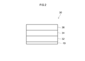
- FIG. 2 is a diagram schematically showing a configuration of a rib wall portion in the exhaust gas purifying catalyst according to the embodiment of the present invention.
- the exhaust gas having lean, stoichiometric, and rich air-fuel ratios means that the exhaust gas exhausted from the internal combustion engine when the lean, stoichiometric, and rich mixed gas is burned in the internal combustion engine, respectively. It refers to an exhaust gas having an air-fuel ratio equivalent to the fuel ratio or an exhaust gas in which hydrocarbon is post-supplied to the exhaust gas.
- the exhaust gas-purifying catalyst disclosed herein comprises a base material and a catalyst coat layer formed on the surface of the base material, and the catalyst coat layer is formed in a laminated structure.
- FIG. 1 is a schematic diagram of a typical example of an exhaust gas purifying catalyst.
- the exhaust gas purifying catalyst 100 includes a honeycomb substrate 10 having a plurality of regularly arranged cells 12 and rib walls 14 constituting the cells 12.
- a honeycomb substrate having a honeycomb structure formed of a cordierite, ceramics such as silicon carbide (SiC), or an alloy (such as stainless steel) can be suitably used.
- a honeycomb base material having a cylindrical outer shape is provided with through holes (cells) as exhaust gas passages in the cylinder axis direction so that exhaust gas can contact partition walls (rib walls) that partition each cell.
- the shape of the substrate may be a foam shape, a pellet shape, etc. in addition to the honeycomb shape.
- the volume (volume) of the base material 10 includes the internal void volume (cell) volume in addition to the pure volume of the base material (that is, the catalyst coat layer formed in the void (cell). (Including volume).
- FIG. 2 is a diagram schematically showing the configuration of the surface portion of the rib wall 14 in the honeycomb substrate 10 of FIG.
- the rib wall 14 includes a base material 10 and a catalyst coat layer 30 having a three-layer structure formed on the surface thereof.
- the catalyst coat layer 30 having a three-layer structure includes a lower layer 32 provided on the substrate 10, a middle layer 34 provided on the lower layer 32, and an upper layer 36 provided on the middle layer 34. Is formed.
- the upper layer 36 includes Rh and Ce-containing oxide.
- the lower layer 32 includes Pd and Ce-containing oxide (oxide containing cerium).
- the middle layer 34 is a Ce-less layer containing Pd and not containing a Ce-containing oxide.
- the ratio (B / A) of the Ce content B in the lower layer 32 to the Ce content A in the upper layer 36 is 2 ⁇ (B / A).
- the Ce-less layer (middle layer) 34 containing Pd is provided between the upper layer 36 on which Rh is arranged and the lower layer 32 on which Pd is arranged, Pd and Ce-containing oxide coexist in the middle layer 34. Therefore, the selective reactivity of HC is increased. For this reason, high HC purification performance is exhibited even in a low temperature state immediately after the engine is started, and Cold HC in exhaust gas can be efficiently purified.
- the Ce-less layer 34 is provided between the lower layer 32 and the upper layer 36, the oxygen storage / release capability (atmosphere relaxation capability) becomes insufficient as a contradiction, and the Hot-NOx purification performance at high load tends to decrease. Can be.
- the middle layer 34 is more effectively relaxed by the upper layer 36 and the lower layer 32 at high load.
- the emission of Hot NOx is suppressed. This is considered to contribute to improvement of HotHNOx purification performance and ColdCHC purification performance.
- the ratio of the Ce content B in the lower layer 32 to the Ce content A in the upper layer 36 (B / A) from the viewpoint of better exerting the effect of including the Ce-containing oxide in both the upper layer 36 and the lower layer 32 Is suitably 2 or more, preferably 2.5 or more, more preferably 3 or more.
- the upper limit of the Ce content ratio is not particularly limited, but it is suitably about 15 or less, preferably 12 or less, more preferably 10 or less (from the viewpoint of better exerting the function as a catalyst). For example, 8 or less).
- the total of the Ce content A in the upper layer 36 and the Ce content B in the lower layer 32 is 30 g / L or more in terms of CeO 2 per 1 L of the base material volume.
- the total content (that is, A + B) is preferably 40 g / L or more, more preferably 45 g / L or more, still more preferably 50 g / L or more, and particularly preferably 55 g / L. That's it.
- the upper limit of the total content (A + B) is not particularly limited, but can be, for example, 100 g / L or less, preferably 90 g / L or less, more preferably 80 g / L or less.
- the total content (A + B) may be, for example, 75 g / L or less, or 70 g / L or less.
- the technique disclosed here can be preferably implemented, for example, in a mode in which the sum of the Ce content A in the upper layer 36 and the Ce content B in the lower layer 32 is 30 g / L or more and 100 g / L or less in terms of CeO 2. .
- the lower layer 32 disclosed here is a Ce-containing layer containing a Ce-containing oxide, and contains Pd as a noble metal catalyst.
- the Ce-containing oxide include CeO 2 (ceria) and CeO 2 -containing composite oxide containing the ceria.
- CeO 2 —ZrO 2 composite oxide the use of ceria-zirconia composite oxide (CeO 2 —ZrO 2 composite oxide) is preferable.
- the Ce content B in the lower layer 32 is not particularly limited as long as it satisfies the above relationship with the Ce content A in the upper layer 36. From the viewpoint of suppressing NOx emission, for example, It is 20 g / L or more, preferably 30 g / L or more, more preferably 40 g / L or more, still more preferably 45 g / L or more, and particularly preferably 50 g / L or more per liter of volume in terms of CeO 2 . Further, the Ce content B in the lower layer 32 is suitably about 90 g / L or less, preferably 80 g / L or less, more preferably 70 g / L or less, still more preferably 60 g / L or less, particularly preferably. Is 55 g / L or less. The technique disclosed herein can be preferably implemented in an embodiment in which the Ce content B in the lower layer 32 is 45 g / L to 55 g / L.
- the mixing ratio of CeO 2 is within the above range, high catalytic activity and OSC (oxygen storage / release capability) can be realized in the lower layer 32 containing Pd.
- the amount of the ceria-zirconia composite oxide in the lower layer 32 is not particularly limited, but from the viewpoint of suppressing the emission of Hot NOx, for example, 80 g / L to 200 g / L, preferably 100 g, per liter of the substrate volume. / L to 180 g / L, more preferably 110 g / L to 150 g / L.
- the lower layer 32 may be a mixture of metal oxides other than Ce-containing oxides (hereinafter also referred to as “non-Ce-containing oxides”).
- non-Ce-containing oxides include aluminum oxide (alumina: Al 2 O 3 ), zirconium oxide (zirconia: ZrO 2 ), and solid solutions thereof.
- Al 2 O 3 is preferable.
- Al 2 O 3 and Ce-containing oxide have a mass mixing ratio (Al 2 O 3 : Ce-containing oxide) in the range of 5:95 to 50:50 (typically 10:90 to 30:70). It is preferable to mix with.
- the content of the non-Ce containing oxide in the lower layer 32 is not particularly limited. For example, 5 g / L to 80 g / L (preferably 10 g / L to 40 g / L, typically 15 g) per liter of the substrate volume. / L to 30 g / L).
- Barium (Ba) may be added to the Ce-containing oxide and the non-Ce-containing oxide in the lower layer 32 disclosed here. It is preferable that the addition amount of Ba satisfies 0.1 to 10 parts by mass in terms of barium sulfate with respect to 100 parts by mass in total of the Ce-containing oxide and the non-Ce-containing oxide. Those satisfying 5 to 5 parts by mass are more preferable, and those satisfying 1 to 3 parts by mass are more preferable.
- the barium content in the lower layer 32 is not particularly limited. For example, 0.1 g / L to 15 g / L (preferably 0.5 g / L to 5 g / L, typically 1 g) per liter of the substrate volume. / L to 3 g / L).
- Other materials may be added to the lower layer 32 as subcomponents.
- substances that can be added to the catalyst layer include rare earth elements such as lanthanum (La) and yttrium (Y), alkaline earth elements such as calcium, and other transition metal elements.
- rare earth elements such as lanthanum and yttrium are preferably used as stabilizers because they can improve the specific surface area at high temperatures without impairing the catalytic function.
- Pd contained in the lower layer 32 disclosed herein is supported on at least one of the Ce-containing oxide and the non-Ce-containing oxide described above.
- the amount of Pd supported is not particularly limited, but ranges from 0.01 parts by mass to 0.5 parts by mass with respect to 100 parts by mass in total of the Ce-containing oxide and the non-Ce-containing oxide contained in the lower layer 32 (for example, 0 0.03 parts by mass to 0.3 parts by mass, preferably 0.05 parts by mass to 0.1 parts by mass).
- the content of Pd in the lower layer 32 is not particularly limited, but for example, 0.05 g / L to 2 g / L, typically 0.1 g / L to 2 g / L (preferably 0 to 1 liter of substrate volume). 0.1 g / L to 0.5 g / L, typically 0.1 g / L to 0.3 g / L).
- the lower layer 32 disclosed herein may contain other noble metal catalyst to the extent that the performance of Pd is not impaired.
- the noble metal catalyst other than Pd include ruthenium (Ru), iridium (Ir), osmium (Os), and the like.
- the molding amount (coating amount) of the lower layer 32 is not particularly limited. For example, 80 g / L to 300 g / L (typically 100 g / L to 250 g / L, for example, 120 g / L to It is preferably about 200 g / L). When the molding amount of the lower layer 32 is too small, the function as the catalyst coat layer may be weakened. Further, if the amount of forming the lower layer 32 is too large, there is a risk of increasing the pressure loss when the exhaust gas passes through the cells of the honeycomb substrate 10.
- the middle layer 34 disclosed here includes Pd as a noble metal catalyst and a carrier supporting the Pd.
- the middle layer 34 is a Ce-less layer that does not contain a Ce-containing oxide.
- the selective reactivity of HC is enhanced.
- the intermediate layer containing Pd less Ce oxygen is not released through Pd when rich. Therefore, the metallization of Pd at the time of restart (for example, immediately after fuel cut or idling stop) is promoted, and the NOx purification performance is improved.
- the carrier carrying Pd of the middle layer 34 disclosed herein may be a non-Ce containing oxide.
- a non-Ce-containing oxide a porous metal oxide having excellent heat resistance is preferably used.
- examples thereof include aluminum oxide (alumina: Al 2 O 3 ), zirconium oxide (zirconia: ZrO 2 ), and solid solutions thereof.
- Al 2 O 3 is preferably used from the viewpoint of durability (particularly heat resistance).
- the content of the carrier in the middle layer 34 is not particularly limited, but for example, 10 g / L to 100 g / L (for example, 20 g / L to 80 g / L, preferably 30 g / L to 60 g / L, per liter of the substrate volume) It is typically 35 g / L to 50 g / L).
- Barium (Ba) may be added to the carrier supporting Pd of the middle layer 34 disclosed here.
- Ba By adding Ba to the support of the middle layer 34, HC poisoning of Pd is suppressed, and catalytic activity (particularly low temperature activity) is improved.
- catalytic activity particularly low temperature activity
- the dispersibility of Pd with respect to the carrier is improved, and sintering associated with Pd grain growth at high temperature is better suppressed.
- the carrier disclosed herein preferably has an addition amount of Ba that satisfies 20 to 80 parts by mass with respect to 100 parts by mass of the carrier in terms of barium sulfate, and 30 to 60 parts by mass. More preferred are those satisfying parts by weight, and even more preferred are those satisfying 40 to 55 parts by weight.
- the content of barium in the middle layer 34 is not particularly limited. For example, 5 g / L to 50 g / L (preferably 10 g / L to 30 g / L, typically 15 g / L to 25 g) per liter of the substrate volume. / L).
- Other materials may be added to the middle layer 34 as subcomponents.
- substances that can be added to the catalyst layer include rare earth elements such as lanthanum (La) and yttrium (Y), alkaline earth elements such as calcium, and other transition metal elements.
- rare earth elements such as lanthanum and yttrium are preferably used as stabilizers because they can improve the specific surface area at high temperatures without impairing the catalytic function.
- Pd contained in the middle layer 34 disclosed herein is supported on a carrier made of the above-mentioned non-Ce containing oxide.
- the amount of Pd supported is not particularly limited, but is in the range of 0.5 to 20 parts by mass (for example, 1 to 10 parts by mass, preferably 3 to 6 parts by mass with respect to 100 parts by mass of the carrier contained in the intermediate layer 34). (Part by mass) is appropriate. If it is less than this, sufficient catalytic activity cannot be obtained, and even if it is supported more than this, the effect is saturated and the cost is disadvantageous.
- the content of Pd in the middle layer 34 is not particularly limited.
- a non-Ce-containing oxide powder can be prepared by impregnating an aqueous solution containing a palladium salt (for example, nitrate) or a palladium complex (for example, a tetraammine complex), followed by drying and baking.
- a palladium salt for example, nitrate
- a palladium complex for example, a tetraammine complex
- the mass ratio (lower layer / middle layer) of Pd arranged in the lower layer 32 to Pd arranged in the middle layer 34 is 0.5 or less (for example, 0.005 to 0.5).
- the mass ratio of Pd is preferably 0.3 or less, more preferably 0.1 or less (for example, 0.01 to 0.1).
- the technique disclosed here can be preferably implemented in an embodiment in which, for example, the mass ratio of Pd disposed in the lower layer 32 to Pd disposed in the intermediate layer 34 is 0.03 to 0.08.
- the middle layer 34 disclosed here may contain other noble metal catalyst to the extent that the performance of Pd is not impaired.
- the noble metal catalyst other than Pd include ruthenium (Ru), iridium (Ir), osmium (Os), and the like.
- the molding amount (coating amount) of the intermediate layer 34 is not particularly limited, but may be, for example, about 20 g / L to 100 g / L (typically 40 g / L to 80 g / L) per liter of the substrate volume. preferable. When the molding amount of the intermediate layer 34 is too small, the function as the catalyst coat layer may be weakened. Further, if the amount of forming the intermediate layer 34 is too large, there is a risk of increasing the pressure loss when the exhaust gas passes through the cell of the base material.
- the upper layer 36 constituting the catalyst coat layer disclosed herein includes Rh as a noble metal catalyst and a carrier supporting the noble metal catalyst.
- the carrier supporting the noble metal catalyst of the upper layer 36 disclosed herein may be a Ce-containing oxide.
- the Ce-containing oxide include CeO 2 (ceria) and CeO 2 -containing composite oxide containing the ceria.
- CeO 2 —ZrO 2 composite oxide the use of ceria-zirconia composite oxide (CeO 2 —ZrO 2 composite oxide) is preferable.
- the load is high (high flow rate)
- the exhaust gas hardly diffuses to the lower layer 32. Therefore, by containing Ce-containing oxide in the upper layer 36 in addition to the lower layer 32, the oxygen storage / release capability is appropriately exhibited at high load (for example, by absorbing oxygen in the upper layer 36, Pd in the middle layer 34 is reduced). Oxygen poisoning is suppressed), and NOx emission can be effectively suppressed.
- the Ce content A in the upper layer 36 is not particularly limited as long as it satisfies the above relationship with the Ce content A in the lower layer 32. From the viewpoint of suppressing NOx emission at high load, for example, It is approximately 1 g / L or more, preferably 3 g / L or more, more preferably 4.5 g / L or more, and further preferably 6 g / L or more, in terms of CeO 2 per liter of the substrate.
- the Ce content A in the upper layer 36 is preferably 30 g / L or less, more preferably 25 g / L or less, and even more preferably 20 g / L in terms of CeO 2 from the viewpoint of easy metalization (activation) of Rh. L or less, particularly preferably 18 g / L or less.
- the technique disclosed here can be preferably implemented in an embodiment in which the content of Ce contained in the upper layer 36 is 6 g / L or more and 18 g / L or less.
- the mixing ratio of CeO 2 is within the above range, high catalytic activity and OSC (oxygen storage / release capability) can be realized in the upper layer 36 containing Rh.
- the amount of the ceria-zirconia composite oxide in the upper layer 36 is not particularly limited, but from the viewpoint of suppressing Hot NOx emission, for example, 20 g / L to 120 g / L, preferably 25 g / L to 1 g of the substrate volume. 100 g / L, more preferably 30 g / L to 90 g / L.
- the upper layer 36 disclosed here may be a mixture of metal oxides other than Ce-containing oxides (non-Ce-containing oxides).
- non-Ce-containing oxides include aluminum oxide (alumina: Al 2 O 3 ), zirconium oxide (zirconia: ZrO 2 ), and solid solutions thereof.
- Al 2 O 3 is preferable.
- Al 2 O 3 and Ce-containing oxide have a mass mixing ratio (Al 2 O 3 : Ce-containing oxide) in the range of 95: 5 to 5:95 (typically 70:30 to 20:80). It is preferable to mix with.
- the content of the non-Ce-containing oxide in the upper layer 36 is not particularly limited, but for example, 5 g / L to 50 g / L (preferably 10 g / L to 40 g / L, typically 15 g per liter of the substrate volume) / L to 30 g / L).
- Other materials may be added to the upper layer 36 as subcomponents.
- substances that can be added to the catalyst layer include rare earth elements such as lanthanum (La) and yttrium (Y), alkaline earth elements such as calcium, and other transition metal elements.
- rare earth elements such as lanthanum and yttrium are preferably used as stabilizers because they can improve the specific surface area at high temperatures without impairing the catalytic function.
- Rh contained in the upper layer 36 disclosed herein is supported on the Ce-containing oxide described above.
- the amount of Rh supported is not particularly limited, but is in the range of 0.05 to 2 parts by mass (for example, 0.1 to 1 part by mass, preferably 100 parts by mass with respect to 100 parts by mass of the Ce-containing oxide contained in the upper layer 36. 0.2 parts by mass to 0.5 parts by mass) is appropriate.
- the content of Rh in the upper layer 36 is not particularly limited. For example, 0.01 g / L to 1 g / L (preferably 0.05 g / L to 0.5 g / L, typically Is preferably 0.1 g / L to 0.3 g / L).
- the mass ratio (Pd / Rh) of Pd arranged in the lower layer 32 and the middle layer 34 to Rh arranged in the upper layer 36 is 2.5 or more (for example, 2.5 to 40, typically 5 to 40). .
- the mass ratio of Pd / Rh is preferably 8 or more, more preferably 10 or more.
- the technique disclosed herein is preferably performed in an embodiment in which the mass ratio of Pd arranged in the lower layer 32 and the middle layer 34 to Rh arranged in the upper layer 36 is 8 to 30 (typically 10 to 15), for example. Can be done.
- the upper layer 36 disclosed here may contain another noble metal catalyst to the extent that the performance of Rh and / or Pt is not impaired.
- the noble metal catalyst other than Pd include ruthenium (Ru), iridium (Ir), osmium (Os), and the like.
- the molding amount (coating amount) of the upper layer 36 is not particularly limited. For example, 50 g / L to 180 g / L (typically 75 g / L to 150 g / L, for example, 90 g / L to 120 g / L) is preferable. When the molding amount of the upper layer 36 is too small, the function as the catalyst coat layer may be weakened. Further, if the amount of forming the upper layer 36 is too large, there is a risk of increasing the pressure loss when the exhaust gas passes through the cells of the honeycomb substrate 10.
- the catalyst coat layer 30 may be formed based on different slurries in the lower layer 32 middle layer 34 and the upper layer 36. For example, a lower layer slurry for forming the lower layer 32, a middle layer slurry for forming the middle layer 34, and an upper layer slurry for forming the upper layer 36 are prepared.
- the lower layer slurry contains Pd and Ce-containing oxides and other lower layer components (for example, barium and the like).
- the upper layer slurry contains a Ce-containing oxide carrying Rh and other upper layer constituents (for example, a non-Ce-containing oxide).
- the lower layer 32 is formed on the surface of the substrate 10 by wash-coating the slurry for the lower layer on the portion of the substrate 10 where the lower layer 32 is formed (here, the entire substrate).
- the intermediate layer 34 is formed on the lower layer 32 by wash-coating the slurry for forming the intermediate layer on a portion where the intermediate layer 34 of the substrate 10 is formed (here, the entire substrate).
- the upper layer 36 is formed on the middle layer 34 by wash-coating the slurry for forming the upper layer on the portion where the upper layer 36 of the substrate 10 is formed (here, the entire substrate). In this manner, the catalyst coat layer 30 including the upper layer 36, the middle layer 34, and the lower layer 32 can be formed.
- the slurry may contain a binder in order to make the slurry properly adhere to the substrate.
- a binder for example, use of alumina sol, silica sol or the like is preferable.
- the viscosity of the slurry may be adjusted as appropriate so that the slurry can easily flow into the cells of the substrate (for example, honeycomb substrate).
- the drying conditions of the slurry coated on the surface of the substrate 10 depend on the shape and dimensions of the substrate or carrier, but typically are about 80 to 300 ° C. (eg 100 to 250 ° C.) for 1 to 10 hours.
- the firing conditions are about 400 to 1000 ° C. (for example, 500 to 700 ° C.) and about 1 to 4 hours.
- the exhaust gas purifying catalyst 100 according to one embodiment of the present invention has been described above, but the present invention is not limited to the above embodiment.
- the catalyst coat layer 30 includes the lower layer 32 provided on the base material 10, the middle layer 34 provided on the lower layer 32, and the upper layer 36 provided on the middle layer 34. However, it may be four or more layers having another layer (for example, another layer formed on the upper layer 36) in addition to the three layers. Further, the catalyst coat layer 30 does not have to have a laminated structure in which the upper layer 36, the middle layer 34, and the lower layer 32 are laminated over the entire area of the substrate (eg, honeycomb substrate) 10, and a part of each layer 32, 34, 36 (eg, A part of the upper layer 36, a part of the middle layer 34, and a part of the lower layer 32) may be partially laminated to form a three-layer structure.
- the substrate eg, honeycomb substrate
- test examples relating to the present invention will be described, but the present invention is not intended to be limited to those shown in the following test examples.
- Example 1 Lower layer forming slurry A by mixing 30 g of alumina powder, Pd nitrate solution (0.1 g of Pd), 125 g of CeO 2 —ZrO 2 composite oxide (50 g of CeO 2 ), 2 g of barium sulfate, and water. Got. Using this lower layer forming slurry A, the entire monolith honeycomb substrate (volume: 1 L) was wash coated, dried at 250 ° C. for 1 hour, and fired at 500 ° C. for 1 hour to form a lower layer on the substrate. Further, 40 g of alumina powder supporting 2 g of Pd, 20 g of barium sulfate, and water were mixed to obtain slurry B for forming an intermediate layer.
- Pd nitrate solution 0.1 g of Pd
- 125 g of CeO 2 —ZrO 2 composite oxide 50 g of CeO 2
- barium sulfate barium sulfate
- a wash coat was applied to the entire honeycomb substrate using this intermediate layer forming slurry B, dried at 250 ° C. for 1 hour, and fired at 500 ° C. for 1 hour to form an intermediate layer on the lower layer. Further, 60 g of CeO 2 —ZrO 2 composite oxide (12 g of CeO 2 ) supporting 0.2 g of Rh, 30 g of alumina powder, and water were mixed to obtain slurry C for forming an upper layer. The upper layer forming slurry C was used to wash coat the entire honeycomb substrate, dried at 250 ° C. for 1 hour, and fired at 500 ° C. for 1 hour to form an upper layer on the middle layer. In this way, an exhaust gas purifying catalyst according to this example was obtained.
- Example 2 For the exhaust gas purification according to the same procedure as in Example 1, except that the amount of CeO 2 —ZrO 2 composite oxide used in the lower layer forming slurry A of Example 1 was changed to 113 g (45 g of CeO 2 ). A catalyst was obtained.
- Example 3 For the exhaust gas purification according to the same procedure as in Example 1, except that the amount of CeO 2 —ZrO 2 composite oxide used in the lower layer forming slurry A of Example 1 was changed to 138 g (55 g of CeO 2 ). A catalyst was obtained.
- Example 4 For the exhaust gas purification according to the same procedure as in Example 1, except that the amount of CeO 2 —ZrO 2 composite oxide used in the upper layer forming slurry C of Example 1 was changed to 30 g (6 g of CeO 2 ). A catalyst was obtained.
- Example 5 For the exhaust gas purification according to the same procedure as in Example 1, except that the amount of CeO 2 —ZrO 2 composite oxide used in the upper layer forming slurry C of Example 1 was changed to 90 g (18 g of CeO 2 ). A catalyst was obtained.
- Example 6 In this example, the amount of CeO 2 —ZrO 2 composite oxide in the upper layer forming slurry C of Example 1 was changed to 45 g (9 g of CeO 2 ), and the same procedure as in Example 1 was used for exhaust gas purification. A catalyst was obtained.
- Example 7 For the exhaust gas purification according to the same procedure as Example 1, except that the amount of CeO 2 —ZrO 2 composite oxide used in the lower layer forming slurry A of Example 1 was changed to 100 g (40 g of CeO 2 ). A catalyst was obtained.
- Example 8 For the exhaust gas purification according to the same procedure as Example 1, except that the amount of CeO 2 —ZrO 2 composite oxide used in the upper layer forming slurry C of Example 1 was changed to 100 g (20 g of CeO 2 ). A catalyst was obtained.
- a lower layer forming slurry D is obtained by mixing 60 g of alumina powder, Pd nitrate solution (2 g of Pd), 125 g of CeO 2 —ZrO 2 composite oxide (50 g of CeO 2 ), 2 g of barium sulfate, and water. It was. Using this lower layer forming slurry D, the entire monolith honeycomb substrate (volume: 1 L) was wash coated, dried at 250 ° C. for 1 hour, and fired at 500 ° C. for 1 hour to form a lower layer.
- slurry E 60 g of CeO 2 —ZrO 2 composite oxide (12 g of CeO 2 ) supporting 0.2 g of Rh, 70 g of alumina powder, and water were mixed to obtain slurry E for forming an upper layer.
- the upper layer forming slurry E was used to wash coat the entire honeycomb substrate (volume: 1 L), dried at 250 ° C. for 1 hour, and fired at 500 ° C. for 1 hour to form an upper layer on the lower layer. In this way, an exhaust gas purifying catalyst according to this example was obtained.
- Example 2 the same procedure as in Example 1 was conducted except that the amount of CeO 2 —ZrO 2 composite oxide used in the lower layer forming slurry A of Example 1 was 0 g (that is, no CeO 2 —ZrO 2 composite oxide was added). An exhaust gas purification catalyst was obtained by the same procedure.
- Example 3 an exhaust gas purification catalyst was obtained in the same procedure as in Example 1 except that 60 g of CeO 2 —ZrO 2 composite oxide was changed to 60 g of ZrO 2 oxide in the upper layer forming slurry C of Example 1.
- the ratio of content B (B / A) is summarized in Table 1.
- the emission amount (g / km) of NOx in the exhaust gas collected in the hot mode is shown in the “Hot NOx” column
- the emission amount (g) of NMHC in the exhaust gas collected in the cold mode (g / Km) is shown in the "Cold HC” column.
- Comparative Examples 2 and 3 in which the CeO 2 —ZrO 2 composite oxide was arranged only in one of the upper layer and the lower layer, and CeO in both the upper layer and the lower layer
- an exhaust gas purifying catalyst capable of realizing both hot-NOx purification performance and Cold-HC purification performance.
Landscapes
- Chemical & Material Sciences (AREA)
- Engineering & Computer Science (AREA)
- Chemical Kinetics & Catalysis (AREA)
- Materials Engineering (AREA)
- Organic Chemistry (AREA)
- Combustion & Propulsion (AREA)
- Health & Medical Sciences (AREA)
- Analytical Chemistry (AREA)
- Biomedical Technology (AREA)
- Environmental & Geological Engineering (AREA)
- General Chemical & Material Sciences (AREA)
- Oil, Petroleum & Natural Gas (AREA)
- Mechanical Engineering (AREA)
- General Engineering & Computer Science (AREA)
- Toxicology (AREA)
- Catalysts (AREA)
- Exhaust Gas Treatment By Means Of Catalyst (AREA)
- Exhaust Gas After Treatment (AREA)
Abstract
L'invention concerne un catalyseur de purification de gaz d'échappement qui comporte une base (10) et une couche de revêtement catalytique (30). La couche de revêtement catalytique (30) est formée de manière à présenter une structure multicouche qui comprend une couche inférieure (32), une couche intermédiaire (34) et une couche supérieure (36). La couche supérieure contient du Rh et un oxyde contenant du Ce. La couche inférieure contient du Pd et un oxyde contenant du Ce. La couche intermédiaire exempte de Ce contient du Pd mais ne contient pas d'oxyde contenant du Ce. Le rapport entre la teneur en Ce [B] dans la couche inférieure (32) et la teneur en Ce [A] dans la couche supérieure (36) satisfait au condition 2 ≤ [B]/[A].
Priority Applications (4)
| Application Number | Priority Date | Filing Date | Title |
|---|---|---|---|
| US16/307,345 US20190136730A1 (en) | 2016-06-07 | 2017-06-05 | Exhaust gas purification catalyst |
| EP17810280.2A EP3466536B1 (fr) | 2016-06-07 | 2017-06-05 | Catalyseur de purification de gaz d'échappement |
| CN201780035140.4A CN109310992A (zh) | 2016-06-07 | 2017-06-05 | 废气净化用催化剂 |
| JP2018522488A JP7043398B2 (ja) | 2016-06-07 | 2017-06-05 | 排ガス浄化用触媒 |
Applications Claiming Priority (2)
| Application Number | Priority Date | Filing Date | Title |
|---|---|---|---|
| JP2016-113471 | 2016-06-07 | ||
| JP2016113471 | 2016-06-07 |
Publications (1)
| Publication Number | Publication Date |
|---|---|
| WO2017213105A1 true WO2017213105A1 (fr) | 2017-12-14 |
Family
ID=60577941
Family Applications (1)
| Application Number | Title | Priority Date | Filing Date |
|---|---|---|---|
| PCT/JP2017/020879 WO2017213105A1 (fr) | 2016-06-07 | 2017-06-05 | Catalyseur de purification de gaz d'échappement |
Country Status (5)
| Country | Link |
|---|---|
| US (1) | US20190136730A1 (fr) |
| EP (1) | EP3466536B1 (fr) |
| JP (1) | JP7043398B2 (fr) |
| CN (1) | CN109310992A (fr) |
| WO (1) | WO2017213105A1 (fr) |
Cited By (3)
| Publication number | Priority date | Publication date | Assignee | Title |
|---|---|---|---|---|
| JP2018143935A (ja) * | 2017-03-02 | 2018-09-20 | エヌ・イーケムキャット株式会社 | 排ガス浄化用触媒 |
| WO2022030240A1 (fr) | 2020-08-07 | 2022-02-10 | 株式会社キャタラー | Catalyseur de purification de gaz d'échappement |
| WO2022209154A1 (fr) * | 2021-03-31 | 2022-10-06 | 三井金属鉱業株式会社 | Catalyseur de purification de gaz d'échappement et système de purification de gaz d'échappement |
Families Citing this family (11)
| Publication number | Priority date | Publication date | Assignee | Title |
|---|---|---|---|---|
| JP6698602B2 (ja) * | 2017-09-27 | 2020-05-27 | イビデン株式会社 | 排ガス浄化用ハニカム触媒 |
| JP2019058875A (ja) * | 2017-09-27 | 2019-04-18 | イビデン株式会社 | ハニカム触媒 |
| JP6684257B2 (ja) * | 2017-09-27 | 2020-04-22 | イビデン株式会社 | 排ガス浄化用ハニカム触媒 |
| JP2019058876A (ja) | 2017-09-27 | 2019-04-18 | イビデン株式会社 | ハニカム触媒 |
| KR102563441B1 (ko) * | 2018-11-12 | 2023-08-03 | 현대자동차 주식회사 | 배출 가스 정화 장치 |
| JP2020163342A (ja) * | 2019-03-29 | 2020-10-08 | 株式会社キャタラー | 排ガス浄化触媒装置 |
| JP7288331B2 (ja) * | 2019-03-29 | 2023-06-07 | 株式会社キャタラー | 排ガス浄化触媒装置 |
| US11642655B2 (en) * | 2020-01-07 | 2023-05-09 | Johnson Matthey Public Limited Company | Multi-region TWC catalysts for gasoline engine exhaust gas treatments |
| JP7248616B2 (ja) * | 2020-03-25 | 2023-03-29 | トヨタ自動車株式会社 | 排ガス浄化用触媒 |
| EP3889404A1 (fr) * | 2020-03-30 | 2021-10-06 | Johnson Matthey Public Limited Company | Catalyseurs de conversion à trois voies (twc) multirégion pour des traitements de gaz d'échappement d'un moteur à essence avec atténuation h2s améliorée |
| CN117651608A (zh) * | 2021-08-13 | 2024-03-05 | 庄信万丰股份有限公司 | 用于三效催化应用的含硫有机化合物辅助的金属纳米粒子合成 |
Citations (6)
| Publication number | Priority date | Publication date | Assignee | Title |
|---|---|---|---|---|
| JPH10296085A (ja) * | 1997-04-30 | 1998-11-10 | Cataler Kogyo Kk | 排ガス浄化用触媒 |
| JP2003112049A (ja) | 2001-10-03 | 2003-04-15 | Tokyo Roki Co Ltd | 3層構造型三元触媒 |
| JP2005506900A (ja) | 2001-10-26 | 2005-03-10 | エンゲルハード・コーポレーシヨン | 層状触媒複合体 |
| JP2009011937A (ja) * | 2007-07-04 | 2009-01-22 | Cataler Corp | 排ガス浄化用触媒 |
| JP2011183319A (ja) | 2010-03-09 | 2011-09-22 | Mazda Motor Corp | 排気ガス浄化用触媒及び排気ガス浄化方法 |
| JP2016113471A (ja) | 2014-12-11 | 2016-06-23 | 花王株式会社 | 親水化処理剤 |
Family Cites Families (9)
| Publication number | Priority date | Publication date | Assignee | Title |
|---|---|---|---|---|
| US7754171B2 (en) * | 2007-02-02 | 2010-07-13 | Basf Corporation | Multilayered catalyst compositions |
| US7922988B2 (en) * | 2007-08-09 | 2011-04-12 | Michel Deeba | Multilayered catalyst compositions |
| US7622096B2 (en) * | 2007-08-09 | 2009-11-24 | Basf Catalysts Llc | Multilayered catalyst compositions |
| US20090175773A1 (en) * | 2008-01-08 | 2009-07-09 | Chen Shau-Lin F | Multilayered Catalyst Compositions |
| US8323599B2 (en) * | 2010-11-22 | 2012-12-04 | Umicore Ag & Co. Kg | Three-way catalyst having an upstream multi-layer catalyst |
| JP5287884B2 (ja) * | 2011-01-27 | 2013-09-11 | トヨタ自動車株式会社 | 排ガス浄化用触媒 |
| JP5807782B2 (ja) * | 2011-12-28 | 2015-11-10 | トヨタ自動車株式会社 | 排ガス浄化用触媒 |
| CN103191734B (zh) * | 2013-03-15 | 2015-02-18 | 无锡威孚环保催化剂有限公司 | 用于汽车尾气处理的三元催化剂 |
| CN105517706B (zh) * | 2013-12-13 | 2018-08-28 | 株式会社科特拉 | 排气净化用催化剂 |
-
2017
- 2017-06-05 JP JP2018522488A patent/JP7043398B2/ja active Active
- 2017-06-05 EP EP17810280.2A patent/EP3466536B1/fr active Active
- 2017-06-05 US US16/307,345 patent/US20190136730A1/en not_active Abandoned
- 2017-06-05 WO PCT/JP2017/020879 patent/WO2017213105A1/fr active Application Filing
- 2017-06-05 CN CN201780035140.4A patent/CN109310992A/zh active Pending
Patent Citations (6)
| Publication number | Priority date | Publication date | Assignee | Title |
|---|---|---|---|---|
| JPH10296085A (ja) * | 1997-04-30 | 1998-11-10 | Cataler Kogyo Kk | 排ガス浄化用触媒 |
| JP2003112049A (ja) | 2001-10-03 | 2003-04-15 | Tokyo Roki Co Ltd | 3層構造型三元触媒 |
| JP2005506900A (ja) | 2001-10-26 | 2005-03-10 | エンゲルハード・コーポレーシヨン | 層状触媒複合体 |
| JP2009011937A (ja) * | 2007-07-04 | 2009-01-22 | Cataler Corp | 排ガス浄化用触媒 |
| JP2011183319A (ja) | 2010-03-09 | 2011-09-22 | Mazda Motor Corp | 排気ガス浄化用触媒及び排気ガス浄化方法 |
| JP2016113471A (ja) | 2014-12-11 | 2016-06-23 | 花王株式会社 | 親水化処理剤 |
Cited By (3)
| Publication number | Priority date | Publication date | Assignee | Title |
|---|---|---|---|---|
| JP2018143935A (ja) * | 2017-03-02 | 2018-09-20 | エヌ・イーケムキャット株式会社 | 排ガス浄化用触媒 |
| WO2022030240A1 (fr) | 2020-08-07 | 2022-02-10 | 株式会社キャタラー | Catalyseur de purification de gaz d'échappement |
| WO2022209154A1 (fr) * | 2021-03-31 | 2022-10-06 | 三井金属鉱業株式会社 | Catalyseur de purification de gaz d'échappement et système de purification de gaz d'échappement |
Also Published As
| Publication number | Publication date |
|---|---|
| JPWO2017213105A1 (ja) | 2019-04-04 |
| EP3466536A4 (fr) | 2019-04-10 |
| JP7043398B2 (ja) | 2022-03-29 |
| CN109310992A (zh) | 2019-02-05 |
| EP3466536A1 (fr) | 2019-04-10 |
| US20190136730A1 (en) | 2019-05-09 |
| EP3466536B1 (fr) | 2020-03-25 |
Similar Documents
| Publication | Publication Date | Title |
|---|---|---|
| WO2017213105A1 (fr) | Catalyseur de purification de gaz d'échappement | |
| JP5807782B2 (ja) | 排ガス浄化用触媒 | |
| JP6864677B2 (ja) | 排ガス浄化用触媒 | |
| WO2017163985A1 (fr) | Catalyseur de purification de gaz d'échappement | |
| JP6460817B2 (ja) | 排ガス浄化用触媒 | |
| US7998896B2 (en) | Exhaust gas purifying catalyst | |
| JP6532823B2 (ja) | 排ガス浄化用触媒 | |
| JP5285131B2 (ja) | 排ガス浄化用触媒 | |
| RU2011107101A (ru) | Удерживающие nox материалы и ловушки, устойчивые к термическому старению | |
| WO2007010899A1 (fr) | Catalyseur de purification des gaz d’échappement | |
| JP2010505607A5 (fr) | ||
| JP5328133B2 (ja) | 排ガス浄化用触媒 | |
| JP6997838B1 (ja) | 排ガス浄化用触媒 | |
| JP2023008520A (ja) | 排ガス浄化用触媒 |
Legal Events
| Date | Code | Title | Description |
|---|---|---|---|
| WWE | Wipo information: entry into national phase |
Ref document number: 2018522488 Country of ref document: JP |
|
| 121 | Ep: the epo has been informed by wipo that ep was designated in this application |
Ref document number: 17810280 Country of ref document: EP Kind code of ref document: A1 |
|
| NENP | Non-entry into the national phase |
Ref country code: DE |
|
| ENP | Entry into the national phase |
Ref document number: 2017810280 Country of ref document: EP Effective date: 20190107 |