WO2017163985A1 - Catalyseur de purification de gaz d'échappement - Google Patents
Catalyseur de purification de gaz d'échappement Download PDFInfo
- Publication number
- WO2017163985A1 WO2017163985A1 PCT/JP2017/010012 JP2017010012W WO2017163985A1 WO 2017163985 A1 WO2017163985 A1 WO 2017163985A1 JP 2017010012 W JP2017010012 W JP 2017010012W WO 2017163985 A1 WO2017163985 A1 WO 2017163985A1
- Authority
- WO
- WIPO (PCT)
- Prior art keywords
- lower layer
- exhaust gas
- layer
- containing oxide
- ceo
- Prior art date
Links
- 239000003054 catalyst Substances 0.000 title claims abstract description 127
- 239000000463 material Substances 0.000 claims abstract description 48
- 238000011144 upstream manufacturing Methods 0.000 claims abstract description 8
- 238000000746 purification Methods 0.000 claims description 65
- 239000002131 composite material Substances 0.000 claims description 62
- 239000000758 substrate Substances 0.000 claims description 50
- MCMNRKCIXSYSNV-UHFFFAOYSA-N ZrO2 Inorganic materials O=[Zr]=O MCMNRKCIXSYSNV-UHFFFAOYSA-N 0.000 claims description 25
- 229910000510 noble metal Inorganic materials 0.000 claims description 25
- 238000002485 combustion reaction Methods 0.000 claims description 6
- 229910052684 Cerium Inorganic materials 0.000 claims description 3
- GWXLDORMOJMVQZ-UHFFFAOYSA-N cerium Chemical compound [Ce] GWXLDORMOJMVQZ-UHFFFAOYSA-N 0.000 claims description 2
- BASFCYQUMIYNBI-UHFFFAOYSA-N platinum Substances [Pt] BASFCYQUMIYNBI-UHFFFAOYSA-N 0.000 abstract description 17
- 239000010410 layer Substances 0.000 abstract 11
- 239000011247 coating layer Substances 0.000 abstract 2
- 239000010970 precious metal Substances 0.000 abstract 2
- 239000007789 gas Substances 0.000 description 95
- KDLHZDBZIXYQEI-UHFFFAOYSA-N palladium Substances [Pd] KDLHZDBZIXYQEI-UHFFFAOYSA-N 0.000 description 65
- 239000002002 slurry Substances 0.000 description 34
- QVGXLLKOCUKJST-UHFFFAOYSA-N atomic oxygen Chemical compound [O] QVGXLLKOCUKJST-UHFFFAOYSA-N 0.000 description 28
- 229910052760 oxygen Inorganic materials 0.000 description 28
- 239000001301 oxygen Substances 0.000 description 28
- 239000010948 rhodium Substances 0.000 description 26
- 238000000034 method Methods 0.000 description 20
- 229910018072 Al 2 O 3 Inorganic materials 0.000 description 12
- 230000003197 catalytic effect Effects 0.000 description 12
- 239000000446 fuel Substances 0.000 description 11
- PNEYBMLMFCGWSK-UHFFFAOYSA-N aluminium oxide Inorganic materials [O-2].[O-2].[O-2].[Al+3].[Al+3] PNEYBMLMFCGWSK-UHFFFAOYSA-N 0.000 description 10
- TZCXTZWJZNENPQ-UHFFFAOYSA-L barium sulfate Chemical compound [Ba+2].[O-]S([O-])(=O)=O TZCXTZWJZNENPQ-UHFFFAOYSA-L 0.000 description 10
- 238000002156 mixing Methods 0.000 description 10
- 230000000694 effects Effects 0.000 description 9
- 230000000052 comparative effect Effects 0.000 description 8
- 239000011248 coating agent Substances 0.000 description 7
- 238000000576 coating method Methods 0.000 description 7
- 229930195733 hydrocarbon Natural products 0.000 description 7
- 229910052788 barium Inorganic materials 0.000 description 6
- DSAJWYNOEDNPEQ-UHFFFAOYSA-N barium atom Chemical compound [Ba] DSAJWYNOEDNPEQ-UHFFFAOYSA-N 0.000 description 6
- 150000002430 hydrocarbons Chemical class 0.000 description 6
- 229910052746 lanthanum Inorganic materials 0.000 description 6
- FZLIPJUXYLNCLC-UHFFFAOYSA-N lanthanum atom Chemical compound [La] FZLIPJUXYLNCLC-UHFFFAOYSA-N 0.000 description 6
- 239000000843 powder Substances 0.000 description 6
- 229910052761 rare earth metal Inorganic materials 0.000 description 6
- 238000012360 testing method Methods 0.000 description 6
- 229910052727 yttrium Inorganic materials 0.000 description 6
- VWQVUPCCIRVNHF-UHFFFAOYSA-N yttrium atom Chemical compound [Y] VWQVUPCCIRVNHF-UHFFFAOYSA-N 0.000 description 6
- 239000013078 crystal Substances 0.000 description 5
- 238000000465 moulding Methods 0.000 description 5
- 229910052763 palladium Inorganic materials 0.000 description 5
- 229910052703 rhodium Inorganic materials 0.000 description 5
- 239000000126 substance Substances 0.000 description 5
- XLYOFNOQVPJJNP-UHFFFAOYSA-N water Substances O XLYOFNOQVPJJNP-UHFFFAOYSA-N 0.000 description 5
- CETPSERCERDGAM-UHFFFAOYSA-N ceric oxide Chemical compound O=[Ce]=O CETPSERCERDGAM-UHFFFAOYSA-N 0.000 description 4
- 229910000422 cerium(IV) oxide Inorganic materials 0.000 description 4
- 238000010586 diagram Methods 0.000 description 4
- 238000001035 drying Methods 0.000 description 4
- 229910044991 metal oxide Inorganic materials 0.000 description 4
- 150000004706 metal oxides Chemical class 0.000 description 4
- 229910052697 platinum Inorganic materials 0.000 description 4
- 229910052723 transition metal Inorganic materials 0.000 description 4
- OYPRJOBELJOOCE-UHFFFAOYSA-N Calcium Chemical compound [Ca] OYPRJOBELJOOCE-UHFFFAOYSA-N 0.000 description 3
- 229910002651 NO3 Inorganic materials 0.000 description 3
- NHNBFGGVMKEFGY-UHFFFAOYSA-N Nitrate Chemical compound [O-][N+]([O-])=O NHNBFGGVMKEFGY-UHFFFAOYSA-N 0.000 description 3
- KJTLSVCANCCWHF-UHFFFAOYSA-N Ruthenium Chemical compound [Ru] KJTLSVCANCCWHF-UHFFFAOYSA-N 0.000 description 3
- 229910052791 calcium Inorganic materials 0.000 description 3
- 239000011575 calcium Substances 0.000 description 3
- 230000007423 decrease Effects 0.000 description 3
- 230000001771 impaired effect Effects 0.000 description 3
- 229910052809 inorganic oxide Inorganic materials 0.000 description 3
- 229910052741 iridium Inorganic materials 0.000 description 3
- GKOZUEZYRPOHIO-UHFFFAOYSA-N iridium atom Chemical compound [Ir] GKOZUEZYRPOHIO-UHFFFAOYSA-N 0.000 description 3
- 239000000203 mixture Substances 0.000 description 3
- 229910052762 osmium Inorganic materials 0.000 description 3
- SYQBFIAQOQZEGI-UHFFFAOYSA-N osmium atom Chemical compound [Os] SYQBFIAQOQZEGI-UHFFFAOYSA-N 0.000 description 3
- TWNQGVIAIRXVLR-UHFFFAOYSA-N oxo(oxoalumanyloxy)alumane Chemical compound O=[Al]O[Al]=O TWNQGVIAIRXVLR-UHFFFAOYSA-N 0.000 description 3
- RVTZCBVAJQQJTK-UHFFFAOYSA-N oxygen(2-);zirconium(4+) Chemical compound [O-2].[O-2].[Zr+4] RVTZCBVAJQQJTK-UHFFFAOYSA-N 0.000 description 3
- 229910052707 ruthenium Inorganic materials 0.000 description 3
- 239000006104 solid solution Substances 0.000 description 3
- 239000003381 stabilizer Substances 0.000 description 3
- 238000010792 warming Methods 0.000 description 3
- 229910001928 zirconium oxide Inorganic materials 0.000 description 3
- 239000004215 Carbon black (E152) Substances 0.000 description 2
- UGFAIRIUMAVXCW-UHFFFAOYSA-N Carbon monoxide Chemical compound [O+]#[C-] UGFAIRIUMAVXCW-UHFFFAOYSA-N 0.000 description 2
- 239000011230 binding agent Substances 0.000 description 2
- WUKWITHWXAAZEY-UHFFFAOYSA-L calcium difluoride Chemical group [F-].[F-].[Ca+2] WUKWITHWXAAZEY-UHFFFAOYSA-L 0.000 description 2
- 229910002091 carbon monoxide Inorganic materials 0.000 description 2
- 239000000919 ceramic Substances 0.000 description 2
- 238000011156 evaluation Methods 0.000 description 2
- 238000005192 partition Methods 0.000 description 2
- 230000009467 reduction Effects 0.000 description 2
- MHOVAHRLVXNVSD-UHFFFAOYSA-N rhodium atom Chemical compound [Rh] MHOVAHRLVXNVSD-UHFFFAOYSA-N 0.000 description 2
- 239000000243 solution Substances 0.000 description 2
- 239000011800 void material Substances 0.000 description 2
- 239000002912 waste gas Substances 0.000 description 2
- 239000000956 alloy Substances 0.000 description 1
- 229910045601 alloy Inorganic materials 0.000 description 1
- 239000007864 aqueous solution Substances 0.000 description 1
- 230000015572 biosynthetic process Effects 0.000 description 1
- 239000000470 constituent Substances 0.000 description 1
- 229910052878 cordierite Inorganic materials 0.000 description 1
- 238000013461 design Methods 0.000 description 1
- JSKIRARMQDRGJZ-UHFFFAOYSA-N dimagnesium dioxido-bis[(1-oxido-3-oxo-2,4,6,8,9-pentaoxa-1,3-disila-5,7-dialuminabicyclo[3.3.1]nonan-7-yl)oxy]silane Chemical compound [Mg++].[Mg++].[O-][Si]([O-])(O[Al]1O[Al]2O[Si](=O)O[Si]([O-])(O1)O2)O[Al]1O[Al]2O[Si](=O)O[Si]([O-])(O1)O2 JSKIRARMQDRGJZ-UHFFFAOYSA-N 0.000 description 1
- 238000006073 displacement reaction Methods 0.000 description 1
- 238000005516 engineering process Methods 0.000 description 1
- 230000002708 enhancing effect Effects 0.000 description 1
- 230000001747 exhibiting effect Effects 0.000 description 1
- 238000010304 firing Methods 0.000 description 1
- 239000006260 foam Substances 0.000 description 1
- 230000006872 improvement Effects 0.000 description 1
- 238000005259 measurement Methods 0.000 description 1
- VNWKTOKETHGBQD-UHFFFAOYSA-N methane Natural products C VNWKTOKETHGBQD-UHFFFAOYSA-N 0.000 description 1
- -1 methane hydrocarbon Chemical class 0.000 description 1
- 230000000116 mitigating effect Effects 0.000 description 1
- 238000012986 modification Methods 0.000 description 1
- 230000004048 modification Effects 0.000 description 1
- 230000003647 oxidation Effects 0.000 description 1
- 238000007254 oxidation reaction Methods 0.000 description 1
- 150000002940 palladium Chemical class 0.000 description 1
- 239000008188 pellet Substances 0.000 description 1
- 231100000572 poisoning Toxicity 0.000 description 1
- 230000000607 poisoning effect Effects 0.000 description 1
- 230000008569 process Effects 0.000 description 1
- 229920006395 saturated elastomer Polymers 0.000 description 1
- RMAQACBXLXPBSY-UHFFFAOYSA-N silicic acid Chemical compound O[Si](O)(O)O RMAQACBXLXPBSY-UHFFFAOYSA-N 0.000 description 1
- HBMJWWWQQXIZIP-UHFFFAOYSA-N silicon carbide Chemical compound [Si+]#[C-] HBMJWWWQQXIZIP-UHFFFAOYSA-N 0.000 description 1
- 238000005245 sintering Methods 0.000 description 1
- 239000010935 stainless steel Substances 0.000 description 1
- 229910001220 stainless steel Inorganic materials 0.000 description 1
- 229910052726 zirconium Inorganic materials 0.000 description 1
Images
Classifications
-
- B—PERFORMING OPERATIONS; TRANSPORTING
- B01—PHYSICAL OR CHEMICAL PROCESSES OR APPARATUS IN GENERAL
- B01D—SEPARATION
- B01D53/00—Separation of gases or vapours; Recovering vapours of volatile solvents from gases; Chemical or biological purification of waste gases, e.g. engine exhaust gases, smoke, fumes, flue gases, aerosols
- B01D53/34—Chemical or biological purification of waste gases
- B01D53/92—Chemical or biological purification of waste gases of engine exhaust gases
- B01D53/94—Chemical or biological purification of waste gases of engine exhaust gases by catalytic processes
- B01D53/9459—Removing one or more of nitrogen oxides, carbon monoxide, or hydrocarbons by multiple successive catalytic functions; systems with more than one different function, e.g. zone coated catalysts
- B01D53/9463—Removing one or more of nitrogen oxides, carbon monoxide, or hydrocarbons by multiple successive catalytic functions; systems with more than one different function, e.g. zone coated catalysts with catalysts positioned on one brick
- B01D53/9468—Removing one or more of nitrogen oxides, carbon monoxide, or hydrocarbons by multiple successive catalytic functions; systems with more than one different function, e.g. zone coated catalysts with catalysts positioned on one brick in different layers
-
- B—PERFORMING OPERATIONS; TRANSPORTING
- B01—PHYSICAL OR CHEMICAL PROCESSES OR APPARATUS IN GENERAL
- B01D—SEPARATION
- B01D53/00—Separation of gases or vapours; Recovering vapours of volatile solvents from gases; Chemical or biological purification of waste gases, e.g. engine exhaust gases, smoke, fumes, flue gases, aerosols
- B01D53/34—Chemical or biological purification of waste gases
- B01D53/92—Chemical or biological purification of waste gases of engine exhaust gases
- B01D53/94—Chemical or biological purification of waste gases of engine exhaust gases by catalytic processes
- B01D53/9445—Simultaneously removing carbon monoxide, hydrocarbons or nitrogen oxides making use of three-way catalysts [TWC] or four-way-catalysts [FWC]
- B01D53/945—Simultaneously removing carbon monoxide, hydrocarbons or nitrogen oxides making use of three-way catalysts [TWC] or four-way-catalysts [FWC] characterised by a specific catalyst
-
- B—PERFORMING OPERATIONS; TRANSPORTING
- B01—PHYSICAL OR CHEMICAL PROCESSES OR APPARATUS IN GENERAL
- B01D—SEPARATION
- B01D53/00—Separation of gases or vapours; Recovering vapours of volatile solvents from gases; Chemical or biological purification of waste gases, e.g. engine exhaust gases, smoke, fumes, flue gases, aerosols
- B01D53/34—Chemical or biological purification of waste gases
- B01D53/92—Chemical or biological purification of waste gases of engine exhaust gases
- B01D53/94—Chemical or biological purification of waste gases of engine exhaust gases by catalytic processes
- B01D53/9459—Removing one or more of nitrogen oxides, carbon monoxide, or hydrocarbons by multiple successive catalytic functions; systems with more than one different function, e.g. zone coated catalysts
- B01D53/9463—Removing one or more of nitrogen oxides, carbon monoxide, or hydrocarbons by multiple successive catalytic functions; systems with more than one different function, e.g. zone coated catalysts with catalysts positioned on one brick
- B01D53/9472—Removing one or more of nitrogen oxides, carbon monoxide, or hydrocarbons by multiple successive catalytic functions; systems with more than one different function, e.g. zone coated catalysts with catalysts positioned on one brick in different zones
-
- B—PERFORMING OPERATIONS; TRANSPORTING
- B01—PHYSICAL OR CHEMICAL PROCESSES OR APPARATUS IN GENERAL
- B01J—CHEMICAL OR PHYSICAL PROCESSES, e.g. CATALYSIS OR COLLOID CHEMISTRY; THEIR RELEVANT APPARATUS
- B01J23/00—Catalysts comprising metals or metal oxides or hydroxides, not provided for in group B01J21/00
- B01J23/10—Catalysts comprising metals or metal oxides or hydroxides, not provided for in group B01J21/00 of rare earths
-
- B—PERFORMING OPERATIONS; TRANSPORTING
- B01—PHYSICAL OR CHEMICAL PROCESSES OR APPARATUS IN GENERAL
- B01J—CHEMICAL OR PHYSICAL PROCESSES, e.g. CATALYSIS OR COLLOID CHEMISTRY; THEIR RELEVANT APPARATUS
- B01J23/00—Catalysts comprising metals or metal oxides or hydroxides, not provided for in group B01J21/00
- B01J23/38—Catalysts comprising metals or metal oxides or hydroxides, not provided for in group B01J21/00 of noble metals
- B01J23/40—Catalysts comprising metals or metal oxides or hydroxides, not provided for in group B01J21/00 of noble metals of the platinum group metals
- B01J23/44—Palladium
-
- B—PERFORMING OPERATIONS; TRANSPORTING
- B01—PHYSICAL OR CHEMICAL PROCESSES OR APPARATUS IN GENERAL
- B01J—CHEMICAL OR PHYSICAL PROCESSES, e.g. CATALYSIS OR COLLOID CHEMISTRY; THEIR RELEVANT APPARATUS
- B01J23/00—Catalysts comprising metals or metal oxides or hydroxides, not provided for in group B01J21/00
- B01J23/38—Catalysts comprising metals or metal oxides or hydroxides, not provided for in group B01J21/00 of noble metals
- B01J23/40—Catalysts comprising metals or metal oxides or hydroxides, not provided for in group B01J21/00 of noble metals of the platinum group metals
- B01J23/46—Ruthenium, rhodium, osmium or iridium
- B01J23/464—Rhodium
-
- B—PERFORMING OPERATIONS; TRANSPORTING
- B01—PHYSICAL OR CHEMICAL PROCESSES OR APPARATUS IN GENERAL
- B01J—CHEMICAL OR PHYSICAL PROCESSES, e.g. CATALYSIS OR COLLOID CHEMISTRY; THEIR RELEVANT APPARATUS
- B01J23/00—Catalysts comprising metals or metal oxides or hydroxides, not provided for in group B01J21/00
- B01J23/38—Catalysts comprising metals or metal oxides or hydroxides, not provided for in group B01J21/00 of noble metals
- B01J23/54—Catalysts comprising metals or metal oxides or hydroxides, not provided for in group B01J21/00 of noble metals combined with metals, oxides or hydroxides provided for in groups B01J23/02 - B01J23/36
- B01J23/56—Platinum group metals
- B01J23/63—Platinum group metals with rare earths or actinides
-
- B—PERFORMING OPERATIONS; TRANSPORTING
- B01—PHYSICAL OR CHEMICAL PROCESSES OR APPARATUS IN GENERAL
- B01J—CHEMICAL OR PHYSICAL PROCESSES, e.g. CATALYSIS OR COLLOID CHEMISTRY; THEIR RELEVANT APPARATUS
- B01J35/00—Catalysts, in general, characterised by their form or physical properties
- B01J35/19—Catalysts containing parts with different compositions
-
- B—PERFORMING OPERATIONS; TRANSPORTING
- B01—PHYSICAL OR CHEMICAL PROCESSES OR APPARATUS IN GENERAL
- B01J—CHEMICAL OR PHYSICAL PROCESSES, e.g. CATALYSIS OR COLLOID CHEMISTRY; THEIR RELEVANT APPARATUS
- B01J35/00—Catalysts, in general, characterised by their form or physical properties
- B01J35/50—Catalysts, in general, characterised by their form or physical properties characterised by their shape or configuration
- B01J35/56—Foraminous structures having flow-through passages or channels, e.g. grids or three-dimensional monoliths
-
- B—PERFORMING OPERATIONS; TRANSPORTING
- B01—PHYSICAL OR CHEMICAL PROCESSES OR APPARATUS IN GENERAL
- B01J—CHEMICAL OR PHYSICAL PROCESSES, e.g. CATALYSIS OR COLLOID CHEMISTRY; THEIR RELEVANT APPARATUS
- B01J37/00—Processes, in general, for preparing catalysts; Processes, in general, for activation of catalysts
- B01J37/02—Impregnation, coating or precipitation
- B01J37/0215—Coating
- B01J37/0228—Coating in several steps
-
- B—PERFORMING OPERATIONS; TRANSPORTING
- B01—PHYSICAL OR CHEMICAL PROCESSES OR APPARATUS IN GENERAL
- B01J—CHEMICAL OR PHYSICAL PROCESSES, e.g. CATALYSIS OR COLLOID CHEMISTRY; THEIR RELEVANT APPARATUS
- B01J37/00—Processes, in general, for preparing catalysts; Processes, in general, for activation of catalysts
- B01J37/02—Impregnation, coating or precipitation
- B01J37/024—Multiple impregnation or coating
- B01J37/0244—Coatings comprising several layers
-
- B—PERFORMING OPERATIONS; TRANSPORTING
- B01—PHYSICAL OR CHEMICAL PROCESSES OR APPARATUS IN GENERAL
- B01J—CHEMICAL OR PHYSICAL PROCESSES, e.g. CATALYSIS OR COLLOID CHEMISTRY; THEIR RELEVANT APPARATUS
- B01J37/00—Processes, in general, for preparing catalysts; Processes, in general, for activation of catalysts
- B01J37/02—Impregnation, coating or precipitation
- B01J37/024—Multiple impregnation or coating
- B01J37/0248—Coatings comprising impregnated particles
-
- F—MECHANICAL ENGINEERING; LIGHTING; HEATING; WEAPONS; BLASTING
- F01—MACHINES OR ENGINES IN GENERAL; ENGINE PLANTS IN GENERAL; STEAM ENGINES
- F01N—GAS-FLOW SILENCERS OR EXHAUST APPARATUS FOR MACHINES OR ENGINES IN GENERAL; GAS-FLOW SILENCERS OR EXHAUST APPARATUS FOR INTERNAL COMBUSTION ENGINES
- F01N3/00—Exhaust or silencing apparatus having means for purifying, rendering innocuous, or otherwise treating exhaust
- F01N3/08—Exhaust or silencing apparatus having means for purifying, rendering innocuous, or otherwise treating exhaust for rendering innocuous
- F01N3/10—Exhaust or silencing apparatus having means for purifying, rendering innocuous, or otherwise treating exhaust for rendering innocuous by thermal or catalytic conversion of noxious components of exhaust
- F01N3/101—Three-way catalysts
-
- F—MECHANICAL ENGINEERING; LIGHTING; HEATING; WEAPONS; BLASTING
- F01—MACHINES OR ENGINES IN GENERAL; ENGINE PLANTS IN GENERAL; STEAM ENGINES
- F01N—GAS-FLOW SILENCERS OR EXHAUST APPARATUS FOR MACHINES OR ENGINES IN GENERAL; GAS-FLOW SILENCERS OR EXHAUST APPARATUS FOR INTERNAL COMBUSTION ENGINES
- F01N3/00—Exhaust or silencing apparatus having means for purifying, rendering innocuous, or otherwise treating exhaust
- F01N3/08—Exhaust or silencing apparatus having means for purifying, rendering innocuous, or otherwise treating exhaust for rendering innocuous
- F01N3/10—Exhaust or silencing apparatus having means for purifying, rendering innocuous, or otherwise treating exhaust for rendering innocuous by thermal or catalytic conversion of noxious components of exhaust
- F01N3/24—Exhaust or silencing apparatus having means for purifying, rendering innocuous, or otherwise treating exhaust for rendering innocuous by thermal or catalytic conversion of noxious components of exhaust characterised by constructional aspects of converting apparatus
- F01N3/28—Construction of catalytic reactors
- F01N3/2803—Construction of catalytic reactors characterised by structure, by material or by manufacturing of catalyst support
- F01N3/2825—Ceramics
- F01N3/2828—Ceramic multi-channel monoliths, e.g. honeycombs
-
- B—PERFORMING OPERATIONS; TRANSPORTING
- B01—PHYSICAL OR CHEMICAL PROCESSES OR APPARATUS IN GENERAL
- B01D—SEPARATION
- B01D2255/00—Catalysts
- B01D2255/10—Noble metals or compounds thereof
- B01D2255/102—Platinum group metals
- B01D2255/1021—Platinum
-
- B—PERFORMING OPERATIONS; TRANSPORTING
- B01—PHYSICAL OR CHEMICAL PROCESSES OR APPARATUS IN GENERAL
- B01D—SEPARATION
- B01D2255/00—Catalysts
- B01D2255/10—Noble metals or compounds thereof
- B01D2255/102—Platinum group metals
- B01D2255/1023—Palladium
-
- B—PERFORMING OPERATIONS; TRANSPORTING
- B01—PHYSICAL OR CHEMICAL PROCESSES OR APPARATUS IN GENERAL
- B01D—SEPARATION
- B01D2255/00—Catalysts
- B01D2255/10—Noble metals or compounds thereof
- B01D2255/102—Platinum group metals
- B01D2255/1025—Rhodium
-
- B—PERFORMING OPERATIONS; TRANSPORTING
- B01—PHYSICAL OR CHEMICAL PROCESSES OR APPARATUS IN GENERAL
- B01D—SEPARATION
- B01D2255/00—Catalysts
- B01D2255/20—Metals or compounds thereof
- B01D2255/206—Rare earth metals
- B01D2255/2065—Cerium
-
- B—PERFORMING OPERATIONS; TRANSPORTING
- B01—PHYSICAL OR CHEMICAL PROCESSES OR APPARATUS IN GENERAL
- B01D—SEPARATION
- B01D2255/00—Catalysts
- B01D2255/40—Mixed oxides
- B01D2255/407—Zr-Ce mixed oxides
-
- B—PERFORMING OPERATIONS; TRANSPORTING
- B01—PHYSICAL OR CHEMICAL PROCESSES OR APPARATUS IN GENERAL
- B01D—SEPARATION
- B01D2255/00—Catalysts
- B01D2255/90—Physical characteristics of catalysts
- B01D2255/902—Multilayered catalyst
- B01D2255/9022—Two layers
-
- B—PERFORMING OPERATIONS; TRANSPORTING
- B01—PHYSICAL OR CHEMICAL PROCESSES OR APPARATUS IN GENERAL
- B01D—SEPARATION
- B01D2255/00—Catalysts
- B01D2255/90—Physical characteristics of catalysts
- B01D2255/903—Multi-zoned catalysts
- B01D2255/9032—Two zones
-
- B—PERFORMING OPERATIONS; TRANSPORTING
- B01—PHYSICAL OR CHEMICAL PROCESSES OR APPARATUS IN GENERAL
- B01D—SEPARATION
- B01D2255/00—Catalysts
- B01D2255/90—Physical characteristics of catalysts
- B01D2255/908—O2-storage component incorporated in the catalyst
-
- B—PERFORMING OPERATIONS; TRANSPORTING
- B01—PHYSICAL OR CHEMICAL PROCESSES OR APPARATUS IN GENERAL
- B01D—SEPARATION
- B01D2257/00—Components to be removed
- B01D2257/40—Nitrogen compounds
- B01D2257/404—Nitrogen oxides other than dinitrogen oxide
-
- B—PERFORMING OPERATIONS; TRANSPORTING
- B01—PHYSICAL OR CHEMICAL PROCESSES OR APPARATUS IN GENERAL
- B01D—SEPARATION
- B01D2257/00—Components to be removed
- B01D2257/50—Carbon oxides
- B01D2257/502—Carbon monoxide
-
- B—PERFORMING OPERATIONS; TRANSPORTING
- B01—PHYSICAL OR CHEMICAL PROCESSES OR APPARATUS IN GENERAL
- B01D—SEPARATION
- B01D2257/00—Components to be removed
- B01D2257/70—Organic compounds not provided for in groups B01D2257/00 - B01D2257/602
- B01D2257/702—Hydrocarbons
-
- B—PERFORMING OPERATIONS; TRANSPORTING
- B01—PHYSICAL OR CHEMICAL PROCESSES OR APPARATUS IN GENERAL
- B01D—SEPARATION
- B01D2258/00—Sources of waste gases
- B01D2258/01—Engine exhaust gases
- B01D2258/014—Stoichiometric gasoline engines
-
- F—MECHANICAL ENGINEERING; LIGHTING; HEATING; WEAPONS; BLASTING
- F01—MACHINES OR ENGINES IN GENERAL; ENGINE PLANTS IN GENERAL; STEAM ENGINES
- F01N—GAS-FLOW SILENCERS OR EXHAUST APPARATUS FOR MACHINES OR ENGINES IN GENERAL; GAS-FLOW SILENCERS OR EXHAUST APPARATUS FOR INTERNAL COMBUSTION ENGINES
- F01N2330/00—Structure of catalyst support or particle filter
- F01N2330/06—Ceramic, e.g. monoliths
-
- F—MECHANICAL ENGINEERING; LIGHTING; HEATING; WEAPONS; BLASTING
- F01—MACHINES OR ENGINES IN GENERAL; ENGINE PLANTS IN GENERAL; STEAM ENGINES
- F01N—GAS-FLOW SILENCERS OR EXHAUST APPARATUS FOR MACHINES OR ENGINES IN GENERAL; GAS-FLOW SILENCERS OR EXHAUST APPARATUS FOR INTERNAL COMBUSTION ENGINES
- F01N2370/00—Selection of materials for exhaust purification
- F01N2370/02—Selection of materials for exhaust purification used in catalytic reactors
-
- F—MECHANICAL ENGINEERING; LIGHTING; HEATING; WEAPONS; BLASTING
- F01—MACHINES OR ENGINES IN GENERAL; ENGINE PLANTS IN GENERAL; STEAM ENGINES
- F01N—GAS-FLOW SILENCERS OR EXHAUST APPARATUS FOR MACHINES OR ENGINES IN GENERAL; GAS-FLOW SILENCERS OR EXHAUST APPARATUS FOR INTERNAL COMBUSTION ENGINES
- F01N2510/00—Surface coverings
- F01N2510/06—Surface coverings for exhaust purification, e.g. catalytic reaction
- F01N2510/068—Surface coverings for exhaust purification, e.g. catalytic reaction characterised by the distribution of the catalytic coatings
- F01N2510/0682—Surface coverings for exhaust purification, e.g. catalytic reaction characterised by the distribution of the catalytic coatings having a discontinuous, uneven or partially overlapping coating of catalytic material, e.g. higher amount of material upstream than downstream or vice versa
-
- F—MECHANICAL ENGINEERING; LIGHTING; HEATING; WEAPONS; BLASTING
- F01—MACHINES OR ENGINES IN GENERAL; ENGINE PLANTS IN GENERAL; STEAM ENGINES
- F01N—GAS-FLOW SILENCERS OR EXHAUST APPARATUS FOR MACHINES OR ENGINES IN GENERAL; GAS-FLOW SILENCERS OR EXHAUST APPARATUS FOR INTERNAL COMBUSTION ENGINES
- F01N2510/00—Surface coverings
- F01N2510/06—Surface coverings for exhaust purification, e.g. catalytic reaction
- F01N2510/068—Surface coverings for exhaust purification, e.g. catalytic reaction characterised by the distribution of the catalytic coatings
- F01N2510/0684—Surface coverings for exhaust purification, e.g. catalytic reaction characterised by the distribution of the catalytic coatings having more than one coating layer, e.g. multi-layered coatings
-
- Y—GENERAL TAGGING OF NEW TECHNOLOGICAL DEVELOPMENTS; GENERAL TAGGING OF CROSS-SECTIONAL TECHNOLOGIES SPANNING OVER SEVERAL SECTIONS OF THE IPC; TECHNICAL SUBJECTS COVERED BY FORMER USPC CROSS-REFERENCE ART COLLECTIONS [XRACs] AND DIGESTS
- Y02—TECHNOLOGIES OR APPLICATIONS FOR MITIGATION OR ADAPTATION AGAINST CLIMATE CHANGE
- Y02T—CLIMATE CHANGE MITIGATION TECHNOLOGIES RELATED TO TRANSPORTATION
- Y02T10/00—Road transport of goods or passengers
- Y02T10/10—Internal combustion engine [ICE] based vehicles
- Y02T10/12—Improving ICE efficiencies
Definitions
- the present invention relates to an exhaust gas purifying catalyst. Specifically, the present invention relates to an exhaust gas purifying catalyst including a base material and a catalyst coat layer formed on the surface of the base material. Note that this international application claims priority based on Japanese Patent Application No. 2016-057142 filed on Mar. 22, 2016, the entire contents of which are incorporated herein by reference. ing.
- a three-way catalyst containing at least one of Pt (platinum), Pd (palladium), and Rh (rhodium) noble metals is often used.
- a catalyst coat layer made of alumina is formed on the surface of a high heat-resistant ceramic substrate, and one or more of Pt, Pd, and Rh noble metals are formed on the catalyst coat layer. Two or more kinds are supported.
- Pd mainly contributes to the purification performance of carbon monoxide (CO) and hydrocarbons (HC)
- Rh mainly contributes to the purification performance (reduction purification ability) of NOx. Therefore, by using Pd and Rh in combination, harmful components in the exhaust gas can be efficiently purified at a time.
- the air-fuel ratio which is the mixing ratio of air and gasoline supplied to the engine, must be close to the theoretical air-fuel ratio (stoichiometric).
- a Ce-containing oxide for example, a ceria-zirconia composite oxide
- OSC oxygen storage capacity
- the Ce-containing oxide occludes oxygen in the exhaust gas when the air-fuel ratio of the exhaust gas is lean (ie, the atmosphere on the oxygen excess side), and when the air-fuel ratio of the exhaust gas is rich (ie, the atmosphere on the fuel excess side) Works to release the stored oxygen. Thereby, even when the oxygen concentration in the exhaust gas fluctuates, stable catalyst performance can be obtained, and the purification performance of the catalyst is improved.
- Patent Document 1 discloses an exhaust gas purifying catalyst in which a Pd layer is coated on the entire honeycomb carrier and an Rh layer is coated on the Pd layer.
- the Pd layer has a front stage part and a rear stage part, and an improvement in NOx purification performance is proposed by setting the ratio of the amount of oxygen releasing material between the front stage part and the rear stage part to the front stage> the rear stage. ing.
- the present invention has been made in view of such a case, and its main object is to achieve a high level of compatibility between Cold ⁇ ⁇ ⁇ HC purification performance and Hot NOx purification performance in an exhaust gas purification catalyst having an upper and lower two-layer structure. It is to provide an exhaust gas purifying catalyst that can be used.
- the present inventor has improved the Cold-HC purification performance by providing a Ce-less layer in the front part of the lower layer in the exhaust gas purification catalyst having an upper and lower two-layer structure.
- a Ce-containing oxide having a pyrochlore structure in the latter part of the lower layer can achieve both Cold HC purification performance and Hot NOx purification performance at a high level.
- the exhaust gas purifying catalyst provided by the present invention is an exhaust gas purifying catalyst that is disposed in the exhaust passage of the internal combustion engine and purifies NOx contained in the exhaust gas. And a formed catalyst coat layer.
- the catalyst coat layer is formed in a laminated structure having upper and lower layers having a layer closer to the substrate surface as a lower layer and a relatively far side as an upper layer.
- the upper layer contains Rh and / or Pt and a Ce-containing oxide as a noble metal catalyst.
- the lower layer contains Pd as a noble metal catalyst.
- the lower layer includes a front lower layer located upstream and a rear lower layer located downstream in the flow direction of the exhaust gas.
- the preceding lower layer is a Ce-less layer that does not contain a Ce-containing oxide.
- the lower layer is a Ce-containing layer containing a Ce-containing oxide having a pyrochlore structure.
- the warming performance of the catalyst is effectively improved by providing the Ce-less layer that does not include the Ce-containing oxide in the former stage portion of the lower layer where Pd is disposed. Therefore, high catalytic activity is exhibited even in a low temperature state immediately after the engine is started, and Cold HC in the exhaust gas can be purified well.
- a Ce-less layer is provided in the former part of the lower layer in order to improve the Cold HC purification performance, the Hot NOx purification performance may tend to decrease as a contradiction, but according to the configuration of the present invention, By including a pyrochlore-type Ce-containing oxide in the latter part, it is possible to effectively suppress a decrease in the hot-NOx purification performance. Therefore, according to the present invention, it is possible to provide an optimal exhaust gas purifying catalyst in which the Cold HC purification performance is further improved while suppressing the emission of Hot NOx.
- the Ce amount of the pyrochlore-type structure Ce-containing oxide in the downstream lower layer is 10 g / L to 20 g / L in terms of CeO 2 per liter of the substrate volume. It is. Within the range of the Ce amount of the pyrochlore-type structure Ce-containing oxide contained in such a lower layer, compatibility between Hot NOx purification performance and Cold HC purification performance can be more suitably realized.
- the downstream lower layer further contains a Ce-containing oxide having a non-pyrochlore structure.
- the non-pyrochlore structure Ce-containing oxide has a relatively high oxygen storage rate as compared with the pyrochlore structure Ce-containing oxide. Therefore, by including the non-pyrochlore structure Ce-containing oxide with a high oxygen storage rate, an oxygen storage / release capability (atmosphere mitigation capability) at an appropriate rate can be exhibited during high-load operation, and NOx emission is more effective. Can be suppressed.
- the total amount of Ce of the pyrochlore structure Ce-containing oxide and the non-pyrochlore structure Ce-containing oxide in the lower layer is 100% by mass.
- the Ce content of the pyrochlore structure Ce-containing oxide is 10% by mass to 30% by mass.
- the non-pyrochlore structure Ce-containing oxide having a relatively high oxygen storage rate effectively contributes to purification of Hot-NOx during high-load operation, while the pyrochlore structure Ce-containing oxide having a relatively low oxygen storage rate is This effectively contributes to purification of HotHNOx at the time of restart.
- the Hot ⁇ NOx purification performance during high load operation and the Hot NOx purification during restart The performance can be made compatible at a high level, and the above-described effects can be more suitably exhibited.
- the total amount of Ce of the pyrochlore-type structure Ce-containing oxide and the non-pyrochlore-type structure Ce-containing oxide in the latter lower layer is a volume of the substrate of 1 L.
- Per equivalent of CeO 2 is 60 g / L to 70 g / L.
- the front-stage lower layer is a portion corresponding to at least 30% of the length of the base material from the exhaust gas inlet side end of the base material toward the exhaust gas outlet side. Is formed.
- latter stage lower layer is formed in the part which hits at least 30% of the length of the said base material toward the waste gas inlet side from the edge part by the side of the exhaust gas outlet of the said base material.
- the Ce amount of the Ce-containing oxide in the upper layer is 10 g / L to 20 g / L in terms of CeO 2 per 1 L of the volume of the base material.
- the effect mentioned above can be more exhibited as it is in the range of the amount of Ce contained in such an upper layer.
- the Ce-containing oxide is a ceria-zirconia composite oxide. Since the ceria-zirconia composite oxide has a high oxygen storage / release capability (atmosphere relaxation capability), it can be suitably used as a Ce-containing oxide suitable for the purpose of the present invention.
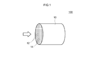
- FIG. 1 is a schematic configuration explanatory diagram of an exhaust gas purifying catalyst according to an embodiment of the present invention.
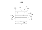
- FIG. 2 is a diagram schematically showing a configuration of a rib wall portion in the exhaust gas purifying catalyst according to the embodiment of the present invention.
- the exhaust gas having lean, stoichiometric, and rich air-fuel ratios means that the exhaust gas exhausted from the internal combustion engine when the lean, stoichiometric, and rich mixed gas is burned in the internal combustion engine, respectively. It refers to an exhaust gas having an air-fuel ratio equivalent to the fuel ratio or an exhaust gas in which hydrocarbon is post-supplied to the exhaust gas.
- the exhaust gas-purifying catalyst disclosed herein comprises a base material and a catalyst coat layer formed on the surface of the base material, and the catalyst coat layer is formed in a laminated structure.
- FIG. 1 is a schematic diagram of a typical example of an exhaust gas purifying catalyst.
- the exhaust gas purifying catalyst 100 includes a honeycomb substrate 10 having a plurality of regularly arranged cells 12 and rib walls 14 constituting the cells 12.
- a honeycomb substrate having a honeycomb structure formed of a cordierite, ceramics such as silicon carbide (SiC), or an alloy (such as stainless steel) can be suitably used.
- a honeycomb base material having a cylindrical outer shape is provided with through holes (cells) as exhaust gas passages in the cylinder axis direction so that exhaust gas can contact partition walls (rib walls) that partition each cell.
- the shape of the substrate may be a foam shape, a pellet shape, etc. in addition to the honeycomb shape.
- the volume (volume) of the base material 10 includes the internal void volume (cell) volume in addition to the pure volume of the base material (that is, the catalyst coat layer formed in the void (cell). (Including volume).
- FIG. 2 is a diagram schematically showing the configuration of the surface portion of the rib wall 14 in the honeycomb substrate 10 of FIG.
- the rib wall 14 includes a base material 10 and a catalyst coat layer 30 having a two-layer structure formed on the surface thereof.
- the two-layered catalyst coat layer 30 is formed in a laminated structure having at least two layers, the lower layer 34 being closer to the surface of the substrate 10 and the upper layer 32 being relatively far away.
- the upper layer 32 includes Rh (rhodium) and / or Pt (platinum) as a noble metal catalyst.
- the lower layer 34 contains Pd (palladium) as a noble metal catalyst.
- the lower layer 34 is provided with the front
- the former lower layer 34a constituting the former part (upstream part) of the lower layer 34 disclosed here includes Pd as a noble metal catalyst and a carrier supporting the Pd.
- the former lower layer 34a is a Ce-less layer that does not include a Ce-containing oxide (an oxide containing cerium).
- the carrier supporting Pd of the former lower layer 34a disclosed here may be a metal oxide other than the Ce-containing oxide (hereinafter also referred to as non-Ce-containing oxide).
- a non-Ce-containing oxide a porous metal oxide having excellent heat resistance is preferably used.
- examples thereof include aluminum oxide (alumina: Al 2 O 3 ), zirconium oxide (zirconia: ZrO 2 ), and solid solutions thereof.
- Al 2 O 3 is preferable.
- Al 2 O 3 has a large surface area and high durability (particularly heat resistance). Therefore, by supporting Pd on Al 2 O 3 , thermal stability can be improved and an appropriate amount of Pd can be supported.
- the content of the carrier in the former lower layer 34a is not particularly limited. For example, it is 40 g to 200 g (for example, 40 g to 100 g, preferably 50 g to 100 g, typically 60 g to 80 g) per liter of the substrate volume. Is preferred.
- Barium (Ba) may be added to the carrier supporting Pd of the former lower layer 34a disclosed herein.
- Ba By adding Ba to the carrier of the former lower layer 34a, by adding Ba to the carrier of the former lower layer 34a, HC poisoning of Pd can be suppressed, and catalytic activity (particularly low temperature activity) can be improved.
- catalytic activity particularly low temperature activity
- the dispersibility of Pd with respect to the carrier is improved, and sintering associated with Pd grain growth at high temperature is better suppressed.
- the carrier disclosed herein preferably has an addition amount of Ba that satisfies 10 to 50 parts by mass with respect to 100 parts by mass of the carrier in terms of barium sulfate, and 15 to 40 parts by mass.
- the barium content in the former lower layer 34a is not particularly limited, but for example, it is preferably 5 to 50 g (preferably 10 to 30 g, typically 15 to 25 g) per liter of the substrate volume.
- Other materials may be added to the front lower layer 34a as subcomponents.
- substances that can be added to the catalyst layer include rare earth elements such as lanthanum (La) and yttrium (Y), alkaline earth elements such as calcium, and other transition metal elements.
- rare earth elements such as lanthanum and yttrium are preferably used as stabilizers because they can improve the specific surface area at high temperatures without impairing the catalytic function.
- Pd contained in the former lower layer 34a disclosed herein is supported on a carrier made of the above-mentioned non-Ce containing oxide.
- the amount of Pd supported is not particularly limited, but is in the range of 0.1 to 10 parts by weight (eg 0.5 to 5 parts by weight, preferably 1 part by weight) with respect to 100 parts by weight of the carrier contained in the former lower layer 34a. Part to 3 parts by mass). If it is less than this, sufficient catalytic activity cannot be obtained, and even if it is supported more than this, the effect is saturated and the cost is disadvantageous.
- the content of Pd in the former lower layer 34a is not particularly limited.
- a non-Ce-containing oxide powder can be prepared by impregnating an aqueous solution containing a palladium salt (for example, nitrate) or a palladium complex (for example, a tetraammine complex), followed by drying and baking.
- a palladium salt for example, nitrate
- a palladium complex for example, a tetraammine complex
- the former lower layer 34a disclosed herein may contain other noble metal catalyst to the extent that the performance of Pd is not impaired.
- the noble metal catalyst other than Pd include ruthenium (Ru), iridium (Ir), osmium (Os), and the like.
- the molding amount (coating amount) of the former lower layer 34a is not particularly limited, but is preferably about 40 g to 200 g (typically 60 g to 100 g) per liter of the substrate volume, for example.
- the amount of the former lower layer 34a is too small, the function as the catalyst coat layer may be weakened. Further, if the amount of the former lower layer 34a is too large, there is a risk of increasing the pressure loss when the exhaust gas passes through the cell of the base material.
- the warming performance of the catalyst is improved. Effectively improved, high Cold HC purification performance can be more reliably exhibited immediately after engine startup.
- the rear lower layer 34b constituting the rear part (downstream part) of the lower layer 34 disclosed here is a Ce-containing layer containing a Ce-containing oxide having a pyrochlore structure, and contains Pd as a noble metal catalyst. .
- Ce-containing layer 34b containing the pyrochlore-type structure Ce-containing oxide in the rear stage portion of the lower layer 34 both the Cold HC purification performance and the Hot NOx purification performance can be realized at a high level.
- the reason why such an effect is obtained is not particularly limited, but may be considered as follows, for example.
- the Ce-less layer 34a is provided in the former stage portion of the lower layer 34 as described above, the Cold HC purification performance is enhanced, but as a contradiction, the oxygen storage / release ability (atmosphere relaxation ability) becomes insufficient, and the Hot NOx purification performance. May tend to decline.
- the oxygen storage / release ability at the time of high load operation or restart (for example, immediately after fuel cut (F / C)).
- the oxygen storage / release capability can be appropriately exhibited, and the reduction of the Hot NOx purification performance can be effectively suppressed. Therefore, according to this aspect, it is possible to realize an optimal exhaust gas purification catalyst in which the Cold HC purification performance is better improved while suppressing the emission of Hot NOx.
- Ce-containing oxide examples include CeO 2 (ceria) -containing composite oxide having a pyrochlore structure.
- CeO 2 ceria
- ZrO 2 composite oxide a ceria-zirconia composite oxide having a pyrochlore structure.
- the pyrochlore structure is represented by A 2 B 2 O 7 when B is a transition metal element, and is a kind of crystal structure composed of a combination of A 3+ / B 4+ or A 2+ / B 5+ This occurs when the ionic radius of A is relatively small in the crystal structure of this configuration.
- the chemical formula of the ceria-zirconia composite oxide having a pyrochlore structure is represented by Ce 2 Zr 2 O 7 , and Ce and Zr are alternately sandwiched with oxygen interposed therebetween. Are regularly arranged. Since the Ce-containing oxide having such a pyrochlore structure has a higher oxygen storage / release capability (atmosphere relaxation capability) than Ce-containing oxides having other crystal structures, the above-described effects can be appropriately exhibited. it can.
- the amount of Ce of the pyrochlore structure Ce-containing oxide in the downstream lower layer 34b is not particularly limited, but from the viewpoint of suppressing the emission of Hot NOx, for example, from 5 g / L in terms of CeO 2 per liter of the substrate volume. It is 25 g / L, preferably 10 g / L to 20 g / L, more preferably 12 g / L to 18 g / L.
- the technique disclosed herein can be preferably implemented in an embodiment in which the Ce content of the pyrochlore structure Ce-containing oxide in the lower layer 34b is 10 g / L to 20 g / L.
- the mixing ratio of CeO 2 is within the above range, high catalytic activity and OSC (oxygen storage capacity) can be realized in the downstream lower layer 34b containing Pd.
- the amount of the pyrochlore-type structure ceria-zirconia composite oxide in the downstream lower layer 34b is not particularly limited, but from the viewpoint of suppressing the emission of Hot NOx, for example, 5 g to 50 g, preferably 10 g, per liter of the substrate volume. -40 g, more preferably 20 g-30 g.
- the rear lower layer 34b may further include a Ce-containing oxide having a non-pyrochlore structure. That is, a Ce-containing oxide having a pyrochlore structure and a Ce-containing oxide having a crystal structure other than the pyrochlore structure may coexist.
- the non-pyrochlore structure Ce-containing oxide include a CeO 2 (ceria) -containing composite oxide having a fluorite structure.
- CeO 2 ceria
- ZrO 2 composite oxide a ceria-zirconia composite oxide having a fluorite structure is preferable.
- both the pyrochlore structure Ce-containing oxide and the non-pyrochlore structure Ce-containing oxide coexisting in the rear lower layer 34b are composed of the same composite oxide (preferably a ceria-zirconia composite oxide). And only the crystal structure is different.
- the non-pyrochlore structure Ce-containing oxide has a relatively high oxygen storage rate as compared with the pyrochlore structure Ce-containing oxide. Therefore, by containing an oxide containing a non-pyrochlore structure Ce having a relatively high oxygen storage rate, an oxygen storage / release capability (atmosphere relaxation capability) at an appropriate rate can be exhibited during high-load operation, and the emission of Hot NOx. Can be suppressed.
- the amount of Ce of the non-pyrochlore structure Ce-containing oxide in the downstream lower layer 34b is not particularly limited, but from the viewpoint of enhancing the NOx purification capacity during high load operation, for example, 30 g to 30 g in terms of CeO 2 per liter of the substrate volume 80 g, preferably 40 g to 70 g, more preferably 45 g to 60 g.
- the mixing ratio of CeO 2 is within the above range, high catalytic activity and OSC (oxygen storage capacity) can be realized in the downstream lower layer 34b containing Pd.
- the amount of the non-pyrochlore structure ceria-zirconia composite oxide in the downstream lower layer 34b is not particularly limited, but from the viewpoint of suppressing Hot NOx emissions, for example, 80 g to 180 g, preferably 100 g to 140 g per liter of the substrate volume. More preferably, it is 110 g to 130 g.
- the pyrochlore structure Ce-containing oxide and the non-pyrochlore structure Ce-containing oxide in the lower layer are used.
- the amount of Ce in the pyrochlore-type Ce-containing oxide is preferably 1% by mass to 40% by mass.
- the non-pyrochlore structure Ce-containing oxide having a relatively high oxygen storage rate effectively contributes to purification of Hot NOx during high-load operation, while the pyrochlore structure Ce-containing oxide having a relatively low oxygen storage rate is This effectively contributes to purification of Hot NOx at the time of restart.
- the Hot NOx purification performance at the time of high load operation and at the time of restart can be made compatible, and the above-described effects can be achieved at a higher level.
- the ratio of Ce of the pyrochlore structure Ce-containing oxide to the total amount of Ce contained in the rear lower layer 34b is 10% by mass to 30% by mass (for example, 10% by mass to 25% by mass, (Typically 12% by mass to 20% by mass) can be preferably implemented.
- the total amount of Ce of the pyrochlore-type structure Ce-containing oxide and the non-pyrochlore-type structure Ce-containing oxide in the downstream lower layer 34b is not particularly limited, but from the viewpoint of Hot NOx purification ability, for example, CeO per liter of substrate volume In terms of 2, it is 40 to 80 g, preferably 50 to 70 g, more preferably 60 to 70 g.
- the technique disclosed herein can be preferably implemented in an embodiment in which the above-mentioned total amount of Ce contained in the rear lower layer 34b is 60 g / L to 70 g / L.
- the rear lower layer 34b disclosed here may be a mixture of metal oxides other than Ce-containing oxides (non-Ce-containing oxides).
- non-Ce-containing oxides include aluminum oxide (alumina: Al 2 O 3 ), zirconium oxide (zirconia: ZrO 2 ), and solid solutions thereof.
- Al 2 O 3 is preferable.
- Al 2 O 3 and Ce-containing oxide have a mass mixing ratio (Al 2 O 3 : Ce-containing oxide) in the range of 5:95 to 50:50 (typically 10:90 to 20:80). It is preferable to mix with.
- the content of the non-Ce-containing oxide in the latter-stage lower layer 34b is not particularly limited. For example, it is 5 to 50 g (preferably 10 to 40 g, typically 15 to 30 g) per liter of the substrate volume. preferable.
- Barium (Ba) may be added to the Ce-containing oxide and the non-Ce-containing oxide in the latter-stage lower layer 34b disclosed here. It is preferable that the addition amount of Ba satisfies 0.1 to 10 parts by mass in terms of barium sulfate with respect to 100 parts by mass in total of the Ce-containing oxide and the non-Ce-containing oxide. Those satisfying 5 to 5 parts by mass are more preferable, and those satisfying 1 to 3 parts by mass are more preferable.
- the content of barium in the downstream lower layer 34b is not particularly limited. For example, 0.1 g / L to 15 g / L (preferably 0.5 g / L to 5 g / L, typically, per liter of the substrate volume) 1 g / L to 3 g / L) is preferable.
- Other materials may be added to the rear lower layer 34b as subcomponents.
- substances that can be added to the catalyst layer include rare earth elements such as lanthanum (La) and yttrium (Y), alkaline earth elements such as calcium, and other transition metal elements.
- rare earth elements such as lanthanum and yttrium are preferably used as stabilizers because they can improve the specific surface area at high temperatures without impairing the catalytic function.
- Pd contained in the rear lower layer 34b disclosed herein is supported on at least one of the Ce-containing oxide and the non-Ce-containing oxide described above.
- the amount of Pd supported is not particularly limited, but ranges from 0.01 parts by mass to 0.5 parts by mass with respect to 100 parts by mass in total of the Ce-containing oxide and the non-Ce-containing oxide contained in the rear lower layer 34b (for example, (0.03 parts by mass to 0.3 parts by mass, preferably 0.05 parts by mass to 0.1 parts by mass).
- the content of Pd in the latter-stage lower layer 34b is not particularly limited.
- 0.01 g / L to 1 g / L (preferably 0.05 g / L to 0.5 g / L, typically, per liter of the substrate volume) Is preferably 0.1 g / L to 0.3 g / L).
- the mass ratio of Pd arranged in the rear lower layer 34b to the Pd arranged in the front lower layer 34a is 0.1 or less (eg, 0.001 to 0.1). .
- the mass ratio of Pd is preferably 0.05 or less, more preferably 0.01 or less (for example, 0.001 to 0.01).
- the technique disclosed herein can be preferably implemented in a mode in which the mass ratio of Pd arranged in the rear lower layer 34b to Pd arranged in the front lower layer 34a is 0.003 to 0.008, for example.
- the rear lower layer 34b disclosed herein may contain other noble metal catalyst to the extent that the performance of Pd is not impaired.
- the noble metal catalyst other than Pd include ruthenium (Ru), iridium (Ir), osmium (Os), and the like.
- the molding amount (coating amount) of the rear lower layer 34b is not particularly limited, but for example, 80 g / L to 300 g / L (typically 100 g / L to 250 g / L, for example, 120 g / L) per liter of the substrate volume. About 200 g / L).
- the molding amount of the rear lower layer 34b is too small, the function as the catalyst coat layer may be weakened.
- the amount of forming the rear lower layer 34b is too large, there is a risk of increasing the pressure loss when the exhaust gas passes through the cells of the honeycomb substrate 10.
- the upper layer 32 constituting the catalyst coat layer disclosed herein includes at least one of Rh and Pt as a noble metal catalyst and a carrier supporting the noble metal catalyst.
- the support carrying the noble metal catalyst of the upper layer 32 disclosed herein may be a Ce-containing oxide.
- the Ce-containing oxide include CeO 2 (ceria) and CeO 2 -containing composite oxide containing the ceria.
- CeO 2 —ZrO 2 composite oxide the use of ceria-zirconia composite oxide (CeO 2 —ZrO 2 composite oxide) is preferable.
- the Ce content of the Ce-containing oxide in the upper layer 32 is not particularly limited, but from the viewpoint of suppressing Hot NOx emissions, for example, approximately 1 g / L to 30 g / L in terms of CeO 2 per liter of the substrate volume, preferably It is 5 g / L to 25 g / L, more preferably 10 g / L to 20 g / L, still more preferably 12 g / L to 18 g / L.
- the technique disclosed herein can be preferably implemented in an embodiment in which the amount of Ce contained in the upper layer 32 is 10 g / L to 20 g / L.
- the mass ratio of Ce contained in the rear lower layer 34b to Ce contained in the upper layer 32 Is appropriately about 2 or more, preferably 2.5 or more, more preferably 3 or more.
- the lower limit of the mass ratio of Ce is not particularly limited. However, from the viewpoint of better exerting the function as a catalyst, it is appropriate that the ratio is approximately 10 or less, preferably 7 or less, more preferably 5 or less (for example, 4 or less).
- the technique disclosed herein can be preferably implemented in a mode in which the mass ratio of Ce contained in the rear lower layer 34b to Ce contained in the upper layer 32 is 2.5-5.
- the mixing ratio of CeO 2 is within the above range, high catalytic activity and OSC (oxygen storage / release capability) can be realized in the upper layer 32 containing Rh and / or Pt.
- the amount of the ceria-zirconia composite oxide in the upper layer 32 is not particularly limited, but from the viewpoint of suppressing Hot NOx emissions, for example, 40 g / L to 120 g / L, preferably 60 g / L to 1 g of the substrate volume. 100 g / L, more preferably 70 g / L to 90 g / L.
- the upper layer 32 disclosed here may be a mixture of metal oxides other than Ce-containing oxides (non-Ce-containing oxides).
- non-Ce-containing oxides include aluminum oxide (alumina: Al 2 O 3 ), zirconium oxide (zirconia: ZrO 2 ), and solid solutions thereof.
- Al 2 O 3 is preferable.
- Al 2 O 3 and Ce-containing oxide have a mass mixing ratio (Al 2 O 3 : Ce-containing oxide) in the range of 10:90 to 50:50 (typically 20:80 to 30:70). It is preferable to mix with.
- the content of the non-Ce-containing oxide in the upper layer 32 is not particularly limited. For example, 5 g / L to 50 g / L (preferably 10 g / L to 40 g / L, typically 15 g) per liter of the substrate volume. / L to 30 g / L).
- Other materials may be added to the upper layer 32 as subcomponents.
- substances that can be added to the catalyst layer include rare earth elements such as lanthanum (La) and yttrium (Y), alkaline earth elements such as calcium, and other transition metal elements.
- rare earth elements such as lanthanum and yttrium are preferably used as stabilizers because they can improve the specific surface area at high temperatures without impairing the catalytic function.
- the Rh and / or Pt contained in the upper layer 32 disclosed herein is supported on the Ce-containing oxide described above.
- the amount of Pd supported is not particularly limited, but is in the range of 0.05 to 2 parts by mass (for example, 0.1 to 1 part by mass, preferably 100 parts by mass of the Ce-containing oxide contained in the downstream lower layer 34b. Is suitably 0.2 parts by mass to 0.5 parts by mass).
- the content of Pd in the latter-stage lower layer 34b is not particularly limited. For example, 0.01 g / L to 1 g / L (preferably 0.05 g / L to 0.5 g / L, typically, per liter of the substrate volume) Is preferably 0.1 g / L to 0.3 g / L).
- the upper layer 32 contains Rh as a noble metal catalyst.
- the mass ratio (Pd / Rh) of Pd arranged in the lower layer 34 (that is, the front lower layer 34a and the rear lower layer 34b) with respect to Rh arranged in the upper layer 32 is 10 or more (for example, 10 to 40).
- the mass ratio of Pd / Rh is preferably 15 or more, more preferably 20 or more.
- the technique disclosed here can be preferably implemented in an embodiment in which, for example, the mass ratio of Pd arranged in the lower layer 34 to Rh arranged in the upper layer 32 is 10 to 30 (typically 15 to 25).
- the upper layer 32 disclosed herein may contain other noble metal catalyst to the extent that the performance of Rh and / or Pt is not impaired.
- the noble metal catalyst other than Pd include ruthenium (Ru), iridium (Ir), osmium (Os), and the like.
- the molding amount (coating amount) of the upper layer 32 is not particularly limited. For example, 50 g / L to 180 g / L (typically 75 g / L to 150 g / L, for example 90 g / L to 120 g / L) is preferable. When the molding amount of the upper layer 32 is too small, the function as the catalyst coat layer may be weakened. Further, if the amount of forming the upper layer 32 is too large, there is a risk of increasing the pressure loss when the exhaust gas passes through the cells of the honeycomb substrate 10.
- the lower layer 34 of the catalyst coat layer 30 may be formed based on different slurries in the front lower layer 34a and the rear lower layer 34b. For example, it is preferable to prepare a slurry for the former lower layer for forming the former lower layer 34a and a slurry for the lower lower layer for forming the latter lower layer 34b.
- the slurry for the former lower layer contains a non-Ce-containing oxide supporting Pd and other former lower layer components (for example, barium).
- the slurry for the downstream layer includes Pd, a pyrochlore structure Ce-containing oxide, and other downstream layer components (for example, non-pyrochlore structure Ce-containing oxide, non-Ce-containing oxide, barium, and the like).
- a part of the lower layer 34 is formed on the surface of the substrate 10 by wash-coating the slurry for the lower layer on the portion of the substrate 10 where the previous lower layer 34 a is formed. This part becomes the previous lower layer 34 a of the lower layer 34.
- the remaining portion of the lower layer 34 is formed on the surface of the substrate 10 by wash-coating the slurry for the lower layer on the remaining portion in the longitudinal direction of the substrate 10. This remaining portion becomes the lower layer 34b of the lower layer 34.
- an upper layer forming slurry for forming the upper layer 32 is prepared.
- This upper layer forming slurry contains Rh and / or Pt and other upper layer constituents (for example, Ce-containing oxide, non-Ce-containing oxide, etc.).
- the upper layer 32 is formed on the lower layer 34 by wash-coating the upper layer forming slurry on the portion where the upper layer 32 of the substrate 10 is formed (here, the entire substrate).
- the catalyst coat layer 30 including the upper layer 32 and the lower layer 34 can be formed.
- the slurry may contain a binder in order to properly adhere the slurry to the surface of the substrate 10 or the surface of the lower layer 34.
- the binder for example, use of alumina sol, silica sol or the like is preferable.
- the viscosity of the slurry may be adjusted as appropriate so that the slurry can easily flow into the cells of the substrate (for example, honeycomb substrate).
- the drying conditions of the slurry coated on the surface of the substrate 10 depend on the shape and dimensions of the substrate or carrier, but typically are about 80 to 300 ° C. (eg 100 to 250 ° C.) for 1 to 10 hours.
- the firing conditions are about 400 to 1000 ° C. (for example, 500 to 700 ° C.) and about 1 to 4 hours.
- the exhaust gas purifying catalyst 100 according to one embodiment of the present invention has been described above, but the present invention is not limited to the above embodiment.
- the stacked structure of the catalyst coat layer 30 is such that the lower layer (Ce-less layer) 34a and the lower layer (Ce-containing layer) 34b containing Pd as described above as the lower layer 34 close to the surface of the substrate 10 are used.
- the layer including the front lower layer (Ce-less layer) 34a and the rear lower layer (Ce-containing layer) 34b containing Pd constitute the lowermost layer in contact with the surface of the base material 10.
- the upper layer 32 containing Rh and / or Pt may be further divided into two layers.
- a layer having a front lower layer 34a containing Pd and a rear lower layer 34b is provided in the lowermost layer in contact with the surface of the base material 10, an intermediate layer containing Pt as a noble metal is provided thereon, and noble metal is provided thereon.
- An uppermost layer containing Rh may be provided.
- the catalyst coat layer 30 does not require the upper layer 32 and the lower layer 34 to have an upper and lower two-layer structure over the entire area of the substrate (for example, the honeycomb substrate) 10. And may be partially laminated.
- test examples relating to the present invention will be described, but the present invention is not intended to be limited to those shown in the following test examples.
- Example 1 20 g of alumina powder, Pd nitrate solution (0.1 g of Pd), 125 g of non-pyrochlore type CeO 2 —ZrO 2 composite oxide (50 g of CeO 2 ), and CeO 2 —ZrO 2 composite oxidation of pyrochlore type structure 25 g (15 g with CeO 2 ), 2 g of barium sulfate, and water were mixed to obtain slurry A for forming the lower layer of the lower stage.
- a wash coat was applied to the portion corresponding to 50% of the length L of the base material from the end on the exhaust gas outflow side to the upstream side of the monolith honeycomb base material (volume 1 L) using the slurry A for lower layer formation, and 250 ° C.
- the latter lower layer 34b was formed by drying for 1 hour and baking at 500 ° C. for 1 hour. Further, 70 g of alumina powder supporting 2 g of Pd, 2 g of barium sulfate, and water were mixed to obtain a slurry B for forming the former lower layer.
- a wash coat is applied to a portion corresponding to 50% of the length L of the base material from the end on the exhaust gas inflow side of the honeycomb base material (volume 1 L) toward the downstream side at 250 ° C.
- the former lower layer 34a was formed by drying for 1 hour and baking at 500 ° C. for 1 hour.
- 75 g of CeO 2 —ZrO 2 composite oxide having a non-pyrochlore structure carrying 0.2 g of Rh (15 g of CeO 2 ), 25 g of alumina powder, and water were mixed to obtain slurry C for forming the upper layer. It was.
- the entire honeycomb substrate (volume: 1 L) was wash coated, dried at 250 ° C. for 1 hour, and fired at 500 ° C. for 1 hour to form the upper layer 32. In this way, an exhaust gas purifying catalyst according to this example was obtained.
- Example 2 This example is the same as Example 1 except that the amount of the non-pyrochlore-type CeO 2 —ZrO 2 composite oxide in the slurry A for forming the lower layer of Example 1 was changed to 113 g (45 g of CeO 2 ). The exhaust gas purification catalyst according to the procedure was obtained.
- Example 3 This example is the same as Example 1 except that the usage amount of the non-pyrochlore-type CeO 2 —ZrO 2 composite oxide in the slurry A for forming the lower layer of Example 1 was changed to 138 g (55 g of CeO 2 ). The exhaust gas purification catalyst according to the procedure was obtained.
- Example 4 In this example, the same procedure as in Example 1 except that the amount of the pyrochlore-type CeO 2 —ZrO 2 composite oxide used in the former lower layer forming slurry B of Example 1 was changed to 17 g (10 g of CeO 2 ). The exhaust gas purification catalyst was obtained.
- Example 5 In this example, the same procedure as in Example 1 except that the amount of the pyrochlore-type CeO 2 —ZrO 2 composite oxide used in the slurry B for forming the lower layer of Example 1 was changed to 33 g (20 g of CeO 2 ). The exhaust gas purification catalyst was obtained.
- Example 6 In this example, the same procedure as in Example 1 except that the amount of the non-pyrochlore-type CeO 2 —ZrO 2 composite oxide in the upper layer forming slurry C of Example 1 was changed to 50 g (10 g of CeO 2 ). The exhaust gas purification catalyst was obtained.
- Example 7 In this example, the same procedure as in Example 1 except that the amount of the non-pyrochlore-type CeO 2 —ZrO 2 composite oxide used in the upper layer forming slurry C of Example 1 was changed to 100 g (20 g of CeO 2 ). The exhaust gas purification catalyst was obtained.
- a lower layer is formed by mixing 60 g of alumina powder, a Pd nitrate solution (2 g of Pd), 100 g of CeO 2 —ZrO 2 composite oxide having a non-pyrochlore structure (40 g of CeO 2 ), 20 g of barium sulfate, and water. Slurry D was obtained. Using this lower layer forming slurry D, the entire monolith honeycomb substrate (volume: 1 L) was wash coated, dried at 250 ° C. for 1 hour, and fired at 500 ° C. for 1 hour to form a lower layer.
- slurry E for forming the upper layer. It was.
- the upper layer forming slurry E was used to wash coat the entire honeycomb substrate (volume: 1 L), dried at 250 ° C. for 1 hour, and fired at 500 ° C. for 1 hour to form an upper layer. In this way, an exhaust gas purifying catalyst according to this example was obtained.
- the former lower layer was formed by adding 40 g of non-pyrochlore-type CeO 2 —ZrO 2 composite oxide (16 g of CeO 2 ) to the slurry B for forming the lower layer of Example 1 in Example 1.
- the exhaust gas purifying catalyst according to the same procedure as in No. 1 was obtained.
- the exhaust gas purifying catalyst according to each example was attached to a gasoline engine having a displacement of 2000 cc, and an endurance test was conducted at an average engine speed of 3000 rpm and a catalyst inlet gas exhaust gas temperature of 1000 ° C. for 20 hours.
- the emission amount (g / km) of NOx in the exhaust gas collected in the hot mode is shown in the “Hot NOx” column
- the emission amount (g) of NMHC in the exhaust gas collected in the cold mode (g / Km) is shown in the "Cold HC” column.
- the exhaust gas purifying catalysts of Examples 1 to 7 using the pyrochlore structure CeO 2 —ZrO 2 composite oxide in the lower layer of the latter stage are those of Hot NOx.
- the emission amount was 0.093 g / km or less, and the emission of Hot NOx was suppressed as compared with Comparative Examples 3 and 4 in which only the non-pyrochlore structure CeO 2 —ZrO 2 composite oxide was used in the lower layer.
- Example 1 in which the amount of Ce of the pyrochlore structure CeO 2 —ZrO 2 composite oxide in the lower layer was 15 g / L, compared with Examples 4 and 5, the emission of Hot NOx was further suppressed. Further, in Example 1, in which the Ce amount of the non-pyrochlore structure CeO 2 —ZrO 2 composite oxide in the lower layer was 50 g / L, compared with Examples 2 and 3, the emission of Hot NOx was further suppressed. Further, in which the Ce amount of the non-pyrochlore structure CeO 2 —ZrO 2 composite oxide in the upper layer was 15 g / L, compared with Examples 6 and 7, the emission of Hot NOx was further suppressed.
- an exhaust gas purifying catalyst capable of highly achieving both Hot-NOx purification performance and Cold-HC purification performance.
Landscapes
- Chemical & Material Sciences (AREA)
- Engineering & Computer Science (AREA)
- Chemical Kinetics & Catalysis (AREA)
- Materials Engineering (AREA)
- Organic Chemistry (AREA)
- Health & Medical Sciences (AREA)
- Combustion & Propulsion (AREA)
- General Chemical & Material Sciences (AREA)
- Biomedical Technology (AREA)
- Environmental & Geological Engineering (AREA)
- Analytical Chemistry (AREA)
- Oil, Petroleum & Natural Gas (AREA)
- General Engineering & Computer Science (AREA)
- Mechanical Engineering (AREA)
- Toxicology (AREA)
- Ceramic Engineering (AREA)
- Exhaust Gas Treatment By Means Of Catalyst (AREA)
- Catalysts (AREA)
- Exhaust Gas After Treatment (AREA)
Abstract
Priority Applications (4)
| Application Number | Priority Date | Filing Date | Title |
|---|---|---|---|
| JP2018507241A JP6855445B2 (ja) | 2016-03-22 | 2017-03-13 | 排ガス浄化用触媒 |
| CN201780018706.2A CN108778491B (zh) | 2016-03-22 | 2017-03-13 | 废气净化用催化剂 |
| EP17770028.3A EP3434363B1 (fr) | 2016-03-22 | 2017-03-13 | Catalyseur de purification de gaz d'échappement |
| US16/086,865 US10737219B2 (en) | 2016-03-22 | 2017-03-13 | Exhaust gas purifying catalyst |
Applications Claiming Priority (2)
| Application Number | Priority Date | Filing Date | Title |
|---|---|---|---|
| JP2016057142 | 2016-03-22 | ||
| JP2016-057142 | 2016-03-22 |
Publications (1)
| Publication Number | Publication Date |
|---|---|
| WO2017163985A1 true WO2017163985A1 (fr) | 2017-09-28 |
Family
ID=59899469
Family Applications (1)
| Application Number | Title | Priority Date | Filing Date |
|---|---|---|---|
| PCT/JP2017/010012 WO2017163985A1 (fr) | 2016-03-22 | 2017-03-13 | Catalyseur de purification de gaz d'échappement |
Country Status (5)
| Country | Link |
|---|---|
| US (1) | US10737219B2 (fr) |
| EP (1) | EP3434363B1 (fr) |
| JP (1) | JP6855445B2 (fr) |
| CN (1) | CN108778491B (fr) |
| WO (1) | WO2017163985A1 (fr) |
Cited By (4)
| Publication number | Priority date | Publication date | Assignee | Title |
|---|---|---|---|---|
| CN109745974A (zh) * | 2017-11-01 | 2019-05-14 | 丰田自动车株式会社 | 废气净化用催化剂 |
| WO2020202990A1 (fr) * | 2019-03-29 | 2020-10-08 | 株式会社キャタラー | Dispositif de catalyseur de purification de gaz d'échappement |
| EP3722571A4 (fr) * | 2017-12-08 | 2021-09-01 | Johnson Matthey (Shanghai) Chemicals Limited | Nouveau catalyseur à twc, à deux couches et à trois zones dans des applications de gaz d'échappement d'essence |
| WO2022030240A1 (fr) | 2020-08-07 | 2022-02-10 | 株式会社キャタラー | Catalyseur de purification de gaz d'échappement |
Families Citing this family (8)
| Publication number | Priority date | Publication date | Assignee | Title |
|---|---|---|---|---|
| EP3915680A4 (fr) * | 2019-01-22 | 2022-03-09 | Mitsui Mining & Smelting Co., Ltd. | Catalyseur pour purifier un gaz d'échappement |
| JP7195995B2 (ja) * | 2019-03-27 | 2022-12-26 | 株式会社キャタラー | 排ガス浄化用触媒 |
| JP7288331B2 (ja) * | 2019-03-29 | 2023-06-07 | 株式会社キャタラー | 排ガス浄化触媒装置 |
| JP7386651B2 (ja) * | 2019-09-02 | 2023-11-27 | 株式会社キャタラー | 排ガス浄化用触媒 |
| CN110801833B (zh) * | 2019-10-24 | 2022-11-11 | 浙江达峰汽车技术有限公司 | 一种汽车尾气净化催化剂定域化涂层及其制备方法 |
| CN117651608A (zh) * | 2021-08-13 | 2024-03-05 | 庄信万丰股份有限公司 | 用于三效催化应用的含硫有机化合物辅助的金属纳米粒子合成 |
| CN115555032A (zh) * | 2022-09-23 | 2023-01-03 | 无锡威孚环保催化剂有限公司 | 一种抑制硫中毒的高性能净化尾气催化剂及其制备方法 |
| CN115920884B (zh) * | 2022-11-03 | 2024-05-17 | 无锡威孚环保催化剂有限公司 | 一种降低thc排放的三效催化剂及其制备方法 |
Citations (4)
| Publication number | Priority date | Publication date | Assignee | Title |
|---|---|---|---|---|
| JP2007021456A (ja) * | 2005-07-21 | 2007-02-01 | Cataler Corp | 排ガス浄化用触媒 |
| WO2010064497A1 (fr) * | 2008-12-03 | 2010-06-10 | 第一稀元素化学工業株式会社 | Catalyseur de purification de gaz d'échappement, appareil de purification de gaz d'échappement utilisant ce catalyseur et procédé de purification de gaz d'échappement |
| JP2012152702A (ja) * | 2011-01-27 | 2012-08-16 | Toyota Motor Corp | 排ガス浄化用触媒 |
| JP2015093267A (ja) * | 2013-11-14 | 2015-05-18 | トヨタ自動車株式会社 | 排ガス浄化触媒 |
Family Cites Families (11)
| Publication number | Priority date | Publication date | Assignee | Title |
|---|---|---|---|---|
| KR100584795B1 (ko) * | 1998-04-28 | 2006-06-02 | 엥겔하드 코포레이션 | 단일체 촉매 및 관련 제조공정 |
| CN101568381B (zh) * | 2007-02-01 | 2012-05-09 | 第一稀元素化学工业株式会社 | 用于机动车废气净化装置中的催化剂体系、使用该催化剂体系的废气净化装置及废气净化方法 |
| US7622096B2 (en) * | 2007-08-09 | 2009-11-24 | Basf Catalysts Llc | Multilayered catalyst compositions |
| US20090175773A1 (en) * | 2008-01-08 | 2009-07-09 | Chen Shau-Lin F | Multilayered Catalyst Compositions |
| JP5218092B2 (ja) | 2009-01-23 | 2013-06-26 | トヨタ自動車株式会社 | 排ガス浄化用触媒 |
| JP2011212639A (ja) | 2010-04-02 | 2011-10-27 | Toyota Motor Corp | 自動車排ガス浄化用触媒 |
| US8323599B2 (en) | 2010-11-22 | 2012-12-04 | Umicore Ag & Co. Kg | Three-way catalyst having an upstream multi-layer catalyst |
| US8557204B2 (en) * | 2010-11-22 | 2013-10-15 | Umicore Ag & Co. Kg | Three-way catalyst having an upstream single-layer catalyst |
| JP5376261B2 (ja) * | 2011-03-10 | 2013-12-25 | トヨタ自動車株式会社 | 排ガス浄化用触媒 |
| JP5720950B2 (ja) * | 2011-12-22 | 2015-05-20 | トヨタ自動車株式会社 | 排ガス浄化装置 |
| EP3020474A4 (fr) * | 2013-07-10 | 2017-04-26 | Cataler Corporation | Catalyseur pour la purification de gaz d'échappement |
-
2017
- 2017-03-13 EP EP17770028.3A patent/EP3434363B1/fr active Active
- 2017-03-13 JP JP2018507241A patent/JP6855445B2/ja active Active
- 2017-03-13 US US16/086,865 patent/US10737219B2/en active Active
- 2017-03-13 WO PCT/JP2017/010012 patent/WO2017163985A1/fr active Application Filing
- 2017-03-13 CN CN201780018706.2A patent/CN108778491B/zh active Active
Patent Citations (4)
| Publication number | Priority date | Publication date | Assignee | Title |
|---|---|---|---|---|
| JP2007021456A (ja) * | 2005-07-21 | 2007-02-01 | Cataler Corp | 排ガス浄化用触媒 |
| WO2010064497A1 (fr) * | 2008-12-03 | 2010-06-10 | 第一稀元素化学工業株式会社 | Catalyseur de purification de gaz d'échappement, appareil de purification de gaz d'échappement utilisant ce catalyseur et procédé de purification de gaz d'échappement |
| JP2012152702A (ja) * | 2011-01-27 | 2012-08-16 | Toyota Motor Corp | 排ガス浄化用触媒 |
| JP2015093267A (ja) * | 2013-11-14 | 2015-05-18 | トヨタ自動車株式会社 | 排ガス浄化触媒 |
Non-Patent Citations (1)
| Title |
|---|
| See also references of EP3434363A4 * |
Cited By (11)
| Publication number | Priority date | Publication date | Assignee | Title |
|---|---|---|---|---|
| CN109745974A (zh) * | 2017-11-01 | 2019-05-14 | 丰田自动车株式会社 | 废气净化用催化剂 |
| JP2019084467A (ja) * | 2017-11-01 | 2019-06-06 | トヨタ自動車株式会社 | 排ガス浄化用触媒 |
| CN109745974B (zh) * | 2017-11-01 | 2022-04-19 | 丰田自动车株式会社 | 废气净化用催化剂 |
| EP3722571A4 (fr) * | 2017-12-08 | 2021-09-01 | Johnson Matthey (Shanghai) Chemicals Limited | Nouveau catalyseur à twc, à deux couches et à trois zones dans des applications de gaz d'échappement d'essence |
| US11110447B2 (en) | 2017-12-08 | 2021-09-07 | Johnson Matthey (shanghai) Chemicals Co., Ltd. | Three-zone two-layer TWC catalyst in gasoline waste gas applications |
| US11577234B2 (en) | 2017-12-08 | 2023-02-14 | Johnson Matthey (Shanghai) Chemicals Limited | Three-zone two-layer TWC catalyst in gasoline waste gas applications |
| WO2020202990A1 (fr) * | 2019-03-29 | 2020-10-08 | 株式会社キャタラー | Dispositif de catalyseur de purification de gaz d'échappement |
| JP2020163342A (ja) * | 2019-03-29 | 2020-10-08 | 株式会社キャタラー | 排ガス浄化触媒装置 |
| EP3950120A4 (fr) * | 2019-03-29 | 2022-12-21 | Cataler Corporation | Dispositif de catalyseur de purification de gaz d'échappement |
| US11883797B2 (en) | 2019-03-29 | 2024-01-30 | Cataler Corporation | Exhaust gas purification catalyst device |
| WO2022030240A1 (fr) | 2020-08-07 | 2022-02-10 | 株式会社キャタラー | Catalyseur de purification de gaz d'échappement |
Also Published As
| Publication number | Publication date |
|---|---|
| JP6855445B2 (ja) | 2021-04-07 |
| EP3434363B1 (fr) | 2021-01-13 |
| EP3434363A4 (fr) | 2019-02-27 |
| CN108778491A (zh) | 2018-11-09 |
| US10737219B2 (en) | 2020-08-11 |
| CN108778491B (zh) | 2021-04-20 |
| JPWO2017163985A1 (ja) | 2019-02-07 |
| US20190083932A1 (en) | 2019-03-21 |
| EP3434363A1 (fr) | 2019-01-30 |
Similar Documents
| Publication | Publication Date | Title |
|---|---|---|
| WO2017163985A1 (fr) | Catalyseur de purification de gaz d'échappement | |
| JP7043398B2 (ja) | 排ガス浄化用触媒 | |
| JP5807782B2 (ja) | 排ガス浄化用触媒 | |
| JP6864677B2 (ja) | 排ガス浄化用触媒 | |
| CN109789388B (zh) | 排气净化用催化剂 | |
| JP5021188B2 (ja) | 排ガス浄化用触媒 | |
| JP6964580B2 (ja) | 排ガス浄化用触媒 | |
| JP6460817B2 (ja) | 排ガス浄化用触媒 | |
| WO2015079908A1 (fr) | Catalyseur de purification de gaz d'échappement | |
| JP2007021456A (ja) | 排ガス浄化用触媒 | |
| WO2015076403A1 (fr) | Catalyseur pour une purification de gaz d'échappement | |
| JP5328133B2 (ja) | 排ガス浄化用触媒 | |
| JP7288331B2 (ja) | 排ガス浄化触媒装置 | |
| JP6997838B1 (ja) | 排ガス浄化用触媒 | |
| WO2023153116A1 (fr) | Dispositif catalytique de purification de gaz d'échappement | |
| JP2023008520A (ja) | 排ガス浄化用触媒 |
Legal Events
| Date | Code | Title | Description |
|---|---|---|---|
| ENP | Entry into the national phase |
Ref document number: 2018507241 Country of ref document: JP Kind code of ref document: A |
|
| NENP | Non-entry into the national phase |
Ref country code: DE |
|
| WWE | Wipo information: entry into national phase |
Ref document number: 2017770028 Country of ref document: EP |
|
| ENP | Entry into the national phase |
Ref document number: 2017770028 Country of ref document: EP Effective date: 20181022 |
|
| 121 | Ep: the epo has been informed by wipo that ep was designated in this application |
Ref document number: 17770028 Country of ref document: EP Kind code of ref document: A1 |